EP3561432A1 - Electronic device and heat-dissipation device for electronic device - Google Patents
Electronic device and heat-dissipation device for electronic device Download PDFInfo
- Publication number
- EP3561432A1 EP3561432A1 EP19168814.2A EP19168814A EP3561432A1 EP 3561432 A1 EP3561432 A1 EP 3561432A1 EP 19168814 A EP19168814 A EP 19168814A EP 3561432 A1 EP3561432 A1 EP 3561432A1
- Authority
- EP
- European Patent Office
- Prior art keywords
- heat
- dissipation
- guiding
- dissipation flow
- flow
- Prior art date
- Legal status (The legal status is an assumption and is not a legal conclusion. Google has not performed a legal analysis and makes no representation as to the accuracy of the status listed.)
- Granted
Links
Images


Classifications
-
- F—MECHANICAL ENGINEERING; LIGHTING; HEATING; WEAPONS; BLASTING
- F28—HEAT EXCHANGE IN GENERAL
- F28F—DETAILS OF HEAT-EXCHANGE AND HEAT-TRANSFER APPARATUS, OF GENERAL APPLICATION
- F28F3/00—Plate-like or laminated elements; Assemblies of plate-like or laminated elements
- F28F3/02—Elements or assemblies thereof with means for increasing heat-transfer area, e.g. with fins, with recesses, with corrugations
- F28F3/04—Elements or assemblies thereof with means for increasing heat-transfer area, e.g. with fins, with recesses, with corrugations the means being integral with the element
- F28F3/048—Elements or assemblies thereof with means for increasing heat-transfer area, e.g. with fins, with recesses, with corrugations the means being integral with the element in the form of ribs integral with the element or local variations in thickness of the element, e.g. grooves, microchannels
-
- G—PHYSICS
- G06—COMPUTING OR CALCULATING; COUNTING
- G06F—ELECTRIC DIGITAL DATA PROCESSING
- G06F1/00—Details not covered by groups G06F3/00 - G06F13/00 and G06F21/00
- G06F1/16—Constructional details or arrangements
- G06F1/20—Cooling means
-
- H—ELECTRICITY
- H05—ELECTRIC TECHNIQUES NOT OTHERWISE PROVIDED FOR
- H05K—PRINTED CIRCUITS; CASINGS OR CONSTRUCTIONAL DETAILS OF ELECTRIC APPARATUS; MANUFACTURE OF ASSEMBLAGES OF ELECTRICAL COMPONENTS
- H05K7/00—Constructional details common to different types of electric apparatus
- H05K7/20—Modifications to facilitate cooling, ventilating, or heating
- H05K7/20009—Modifications to facilitate cooling, ventilating, or heating using a gaseous coolant in electronic enclosures
- H05K7/20136—Forced ventilation, e.g. by fans
- H05K7/20145—Means for directing air flow, e.g. ducts, deflectors, plenum or guides
-
- F—MECHANICAL ENGINEERING; LIGHTING; HEATING; WEAPONS; BLASTING
- F28—HEAT EXCHANGE IN GENERAL
- F28F—DETAILS OF HEAT-EXCHANGE AND HEAT-TRANSFER APPARATUS, OF GENERAL APPLICATION
- F28F13/00—Arrangements for modifying heat-transfer, e.g. increasing, decreasing
- F28F13/06—Arrangements for modifying heat-transfer, e.g. increasing, decreasing by affecting the pattern of flow of the heat-exchange media
-
- F—MECHANICAL ENGINEERING; LIGHTING; HEATING; WEAPONS; BLASTING
- F28—HEAT EXCHANGE IN GENERAL
- F28F—DETAILS OF HEAT-EXCHANGE AND HEAT-TRANSFER APPARATUS, OF GENERAL APPLICATION
- F28F9/00—Casings; Header boxes; Auxiliary supports for elements; Auxiliary members within casings
- F28F9/02—Header boxes; End plates
- F28F9/026—Header boxes; End plates with static flow control means, e.g. with means for uniformly distributing heat exchange media into conduits
- F28F9/0265—Header boxes; End plates with static flow control means, e.g. with means for uniformly distributing heat exchange media into conduits by using guiding means or impingement means inside the header box
- F28F9/0268—Header boxes; End plates with static flow control means, e.g. with means for uniformly distributing heat exchange media into conduits by using guiding means or impingement means inside the header box in the form of multiple deflectors for channeling the heat exchange medium
-
- H—ELECTRICITY
- H05—ELECTRIC TECHNIQUES NOT OTHERWISE PROVIDED FOR
- H05K—PRINTED CIRCUITS; CASINGS OR CONSTRUCTIONAL DETAILS OF ELECTRIC APPARATUS; MANUFACTURE OF ASSEMBLAGES OF ELECTRICAL COMPONENTS
- H05K7/00—Constructional details common to different types of electric apparatus
- H05K7/20—Modifications to facilitate cooling, ventilating, or heating
- H05K7/20009—Modifications to facilitate cooling, ventilating, or heating using a gaseous coolant in electronic enclosures
- H05K7/20136—Forced ventilation, e.g. by fans
- H05K7/20154—Heat dissipaters coupled to components
-
- H—ELECTRICITY
- H05—ELECTRIC TECHNIQUES NOT OTHERWISE PROVIDED FOR
- H05K—PRINTED CIRCUITS; CASINGS OR CONSTRUCTIONAL DETAILS OF ELECTRIC APPARATUS; MANUFACTURE OF ASSEMBLAGES OF ELECTRICAL COMPONENTS
- H05K7/00—Constructional details common to different types of electric apparatus
- H05K7/20—Modifications to facilitate cooling, ventilating, or heating
- H05K7/20009—Modifications to facilitate cooling, ventilating, or heating using a gaseous coolant in electronic enclosures
- H05K7/20136—Forced ventilation, e.g. by fans
- H05K7/20172—Fan mounting or fan specifications
-
- H—ELECTRICITY
- H05—ELECTRIC TECHNIQUES NOT OTHERWISE PROVIDED FOR
- H05K—PRINTED CIRCUITS; CASINGS OR CONSTRUCTIONAL DETAILS OF ELECTRIC APPARATUS; MANUFACTURE OF ASSEMBLAGES OF ELECTRICAL COMPONENTS
- H05K7/00—Constructional details common to different types of electric apparatus
- H05K7/20—Modifications to facilitate cooling, ventilating, or heating
- H05K7/2039—Modifications to facilitate cooling, ventilating, or heating characterised by the heat transfer by conduction from the heat generating element to a dissipating body
- H05K7/20409—Outer radiating structures on heat dissipating housings, e.g. fins integrated with the housing
-
- H—ELECTRICITY
- H10—SEMICONDUCTOR DEVICES; ELECTRIC SOLID-STATE DEVICES NOT OTHERWISE PROVIDED FOR
- H10W—GENERIC PACKAGES, INTERCONNECTIONS, CONNECTORS OR OTHER CONSTRUCTIONAL DETAILS OF DEVICES COVERED BY CLASS H10
- H10W40/00—Arrangements for thermal protection or thermal control
- H10W40/20—Arrangements for cooling
- H10W40/22—Arrangements for cooling characterised by their shape, e.g. having conical or cylindrical projections
-
- H—ELECTRICITY
- H10—SEMICONDUCTOR DEVICES; ELECTRIC SOLID-STATE DEVICES NOT OTHERWISE PROVIDED FOR
- H10W—GENERIC PACKAGES, INTERCONNECTIONS, CONNECTORS OR OTHER CONSTRUCTIONAL DETAILS OF DEVICES COVERED BY CLASS H10
- H10W40/00—Arrangements for thermal protection or thermal control
- H10W40/40—Arrangements for thermal protection or thermal control involving heat exchange by flowing fluids
- H10W40/43—Arrangements for thermal protection or thermal control involving heat exchange by flowing fluids by flowing gases, e.g. forced air cooling
Definitions
- This utility model relates to a heat-dissipation device for an electronic device. This utility model further relates to an electronic device including the heat-dissipation device.
- a fan and a set of heat-dissipation fins are arranged in an airflow channel in an existing heat-dissipation device. An airflow from the fan flows along the airflow channel and flows over the surfaces of the heat-dissipation fins to remove heat from the surfaces of the heat-dissipation fins, thus achieving heat dissipation.
- the inventor of this utility model finds that in such a heat-dissipation device, the airflow flowing through the set of heat-dissipation fins is usually uneven, and the velocity of the airflow flowing through the heat-dissipation fins in a central position of the airflow channel is much greater than the velocity of the airflow flowing through the heat-dissipation fins on two sides, which greatly affects the heat dissipation efficiency of the heat-dissipation device.
- the heat-dissipation device that can allow the airflow to evenly flow through the heat-dissipation fins, thus improving the heat dissipation efficiency.
- the heat-dissipation device is also required to have a simple structure and basically does not increase airflow resistance.
- a heat-dissipation device for an electronic device comprising:
- the plurality of elongated heat-dissipation fins extend along a longitudinal direction of the airflow channel respectively and are spaced apart from each other in a transverse direction perpendicular to the longitudinal direction of the airflow channel, and the plurality of heat-dissipation flow-guiding devices are spaced apart from each other in the transverse direction perpendicular to the longitudinal direction of the airflow channel.
- the plurality of heat-dissipation flow-guiding devices further include a third heat-dissipation flow-guiding device between the first heat-dissipation flow-guiding device and the second heat-dissipation flow-guiding device, and a longitudinal distance between the third heat-dissipation flow-guiding device and the airflow source is greater than the distance between the first heat-dissipation flow-guiding device and the airflow source and less than the distance between the second heat-dissipation flow-guiding device and the airflow source.
- the first heat-dissipation flow-guiding device includes one or more first heat-dissipation flow-guiding column rows
- the second heat-dissipation flow-guiding device includes one or more second heat-dissipation flow-guiding column rows
- the third heat-dissipation flow-guiding device includes one or more third heat-dissipation flow-guiding column rows.
- the number of heat-dissipation flow-guiding columns of each third heat-dissipation flow-guiding column row is less than the number of heat-dissipation flow-guiding columns of each first heat-dissipation flow-guiding column row and greater than the number of heat-dissipation flow-guiding columns of each second heat-dissipation flow-guiding column row.
- the number of the heat-dissipation flow-guiding columns of each heat-dissipation flow-guiding column row in the first heat-dissipation flow-guiding column rows, the second heat-dissipation flow-guiding column rows and the third heat-dissipation flow-guiding column rows is descending.
- each heat-dissipation flow-guiding column is selected from a rectangle, a circle, an oval, a diamond, or a triangle.
- the plurality of elongated heat-dissipation fins are parallel to each other.
- the airflow channel is defined by a bottom wall, two side walls and a top wall, and in the transverse direction perpendicular to the longitudinal direction of the airflow channel, each heat-dissipation flow-guiding column row is located between corresponding two adjacent elongated heat-dissipation fins or between the corresponding outermost elongated heat-dissipation fin and the corresponding side wall.
- the airflow channel is defined by a bottom wall, two side walls and a top wall, and in the transverse direction perpendicular to the longitudinal direction of the airflow channel, each heat-dissipation flow-guiding column row is centrally located between corresponding two adjacent elongated heat-dissipation fins or centrally located between the outermost elongated heat-dissipation fin and the corresponding side wall.
- At least some heat-dissipation flow-guiding columns in each heat-dissipation flow-guiding column row of the first heat-dissipation flow-guiding device, the second heat-dissipation flow-guiding device and the third heat-dissipation flow-guiding device are aligned to corresponding heat-dissipation flow-guiding columns in another heat-dissipation flow-guiding column row.
- the heat-dissipation flow-guiding device is an integral extension part of the plurality of elongated heat-dissipation fins.
- the plurality of elongated heat-dissipation fins are parallel to each other, and longitudinal distances between the heat-dissipation flow-guiding devices and the airflow source are ascending in a direction from the center of the airflow channel to the two sides.
- the plurality of heat-dissipation flow-guiding devices are made of aluminum or steel.
- the airflow source is a fan.
- the airflow channel is defined by a bottom wall, two side walls and a top wall, and the side walls include an inclined sidewall portion extending outward in an airflow direction of the airflow channel and located downstream of the airflow source.
- an electronic device comprising the heat-dissipation device for an electronic device as described in the foregoing and an electronic component in thermal communication with the heat-dissipation device.
- orientation or position relations indicated by the terms “center,” “longitudinal,” “transverse,” “upper,” “lower,” “front,” “rear,” “left,” “right,” “vertical,” “horizontal,” “top,” “bottom,” “inside,” “outside” and so on are orientation or position relations shown based on the accompanying drawings, which are only intended to facilitate the description of this utility model and simplify the description, rather than indicate or imply that the device or element referred to must have a specific orientation or be constructed and operated in the specific orientation, and thus cannot be construed as limitations to this utility model.
- first and “second” are used only for description and cannot be construed as indicating or implying relative importance.
- FIG. 1 to FIG. 3 are schematic views showing a heat-dissipation device 100 according to an embodiment of this utility model.
- FIG. 1 is a top view
- FIG. 2 is a three-dimensional view
- FIG. 3 is an enlarged view of a part of FIG. 1 .
- the heat-dissipation device 100 includes an airflow channel 120.
- the airflow channel 120 is defined by a bottom wall 122, two side walls 124, and a top wall (not shown).
- a fan 110, a plurality of heat-dissipation flow-guiding devices 130, and a plurality of heat-dissipation fins 140 are arranged in the airflow channel 120.
- An airflow from the fan 110 flows approximately along a longitudinal direction A of the airflow channel 120, and flows through the plurality of heat-dissipation flow-guiding devices 130 and the plurality of heat-dissipation fins 140 in sequence, and takes away the heat of the heat-dissipation flow-guiding devices 130 and the heat-dissipation fins 140, thus achieving heat dissipation.
- the plurality of heat-dissipation fins 140 include seven heat-dissipation fins arranged in parallel.
- the seven heat-dissipation fins extend along the longitudinal direction of the airflow channel 120 are aligned to each other, and are evenly spaced apart from each other and apart from corresponding side walls.
- the plurality of heat-dissipation flow-guiding devices 130 include eight heat-dissipation flow-guiding column rows.
- the eight heat-dissipation flow-guiding column rows are symmetrically distributed horizontally. In order to save space, the four upper heat-dissipation flow-guiding column rows are mainly described here.
- the plurality of heat-dissipation flow-guiding devices 130 include two heat-dissipation flow-guiding column rows 132a and 132b (or collectively referred to as a heat-dissipation flow-guiding column row 132 or a first heat-dissipation flow-guiding device 132) in central positions of the airflow channel 120 (farthest from the side wall 124), a heat-dissipation flow-guiding column row 136 (or referred to as a second heat-dissipation flow-guiding device 136) in a position on two sides of the airflow channel 120 (adjacent to the side wall 124), and two heat-dissipation flow-guiding column rows 134 (or collectively referred to as heat-dissipation flow-guiding columns 134 or a third heat-dissipation flow-guiding device 134) between the heat-dissipation flow-guiding column rows 132a, 132b and the heat-dissi
- each heat-dissipation flow-guiding column row is located between corresponding two adjacent elongated heat-dissipation fins or between the corresponding outermost elongated heat-dissipation fin and the corresponding side wall.
- the heat-dissipation flow-guiding column row 132b is located between heat-dissipation fins 140a and 140b
- the heat-dissipation flow-guiding column row 134a is located between heat-dissipation fins 140b and 140c
- the heat-dissipation flow-guiding column row 134b is located between heat-dissipation fins 140c and 140d
- the heat-dissipation flow-guiding column row 136 is located between the heat-dissipation fin 140d and the corresponding side wall 124.
- the heat-dissipation flow-guiding column row 132b is centrally located between heat-dissipation fins 140a and 140b
- the heat-dissipation flow-guiding column row 134a is centrally located between heat-dissipation fins 140b and 140c
- the heat-dissipation flow-guiding column row 134b is centrally located between heat-dissipation fins 140c and 140d
- the heat-dissipation flow-guiding column row 136 is centrally located between the heat-dissipation fin 140d and the corresponding side wall 124.
- the heat-dissipation flow-guiding column row 132b includes four heat-dissipation flow-guiding columns
- the heat-dissipation flow-guiding column row 134a includes three heat-dissipation flow-guiding columns
- the heat-dissipation flow-guiding column row 134b includes two heat-dissipation flow-guiding columns
- the heat-dissipation flow-guiding column row 136 includes one heat-dissipation flow-guiding column.
- the corresponding heat-dissipation flow-guiding columns in each heat-dissipation flow-guiding column row are aligned to each other in the transverse direction.
- the first heat-dissipation flow-guiding columns (heat-dissipation flow-guiding columns that are closest to the heat-dissipation fins in the heat-dissipation flow-guiding column rows) in each heat-dissipation flow-guiding column row are aligned to each other (i.e., in identical longitudinal positions)
- the second heat-dissipation flow-guiding columns (heat-dissipation flow-guiding columns that are second closest to the heat-dissipation fins in the heat-dissipation flow-guiding column rows, if any) in each heat-dissipation flow-guiding column row are aligned to each other, and so on.
- longitudinal distances between the two heat-dissipation flow-guiding column rows 132a and 132b (or collectively referred to as heat-dissipation flow-guiding column 132 or first heat-dissipation flow-guiding device 132) in the central positions of the airflow channel and the fan 110 are the shortest. In a direction from the center of the airflow channel to the two sides, the longitudinal distances between the heat-dissipation flow-guiding column rows and the fan are ascending.
- the inventor of this utility model has found that when the heat-dissipation flow-guiding device 130 of this utility model is absent, the airflow from the fan mainly passes through the central position of the airflow channel, that is, the wind speed on two sides of the heat-dissipation fin 140a is maximum, while the wind speed between the heat-dissipation fin 140d and the side wall is very small.
- the longitudinal distances between the two heat-dissipation flow-guiding column rows 132a and 132b and the fan are the shortest. Therefore, the airflow from the fan 110 first encounters the heat-dissipation flow-guiding column rows 132a and 132b.
- the heat-dissipation flow-guiding column row 132b is located between the heat-dissipation fins 140a and 140b, preferably centrally located between the heat-dissipation fins 140a and 140b, and the heat-dissipation flow-guiding column row 134a is located between the heat-dissipation fins 140b and 140c, preferably centrally located between the heat-dissipation fins 140b and 140c.
- a flow path from the fan 110 to the heat-dissipation fins 140a and 140b is affected by the heat-dissipation flow-guiding column row 132b, and a part of the airflow on the flow path is deflected by the heat-dissipation flow-guiding column row 132b to a side of the airflow channel.
- the inventor of this utility model uses fluid mechanics software to carry out numerical simulation on the embodiment shown in FIG. 1 to FIG. 3 and a comparative embodiment.
- the comparative embodiment is basically similar to the embodiment shown in FIG. 1 to FIG. 3 , with the only difference that the comparative embodiment does not include the inclined side wall 124b (that is, the side wall 124a is at a right angle with the side wall 124c) and the heat-dissipation flow-guiding device 30 (correspondingly, compared with the embodiment in FIG. 1 to FIG.
- FIG. 6 is a result of simulation carried out in the embodiment shown in FIG. 1 to FIG. 3
- FIG. 5 is a result of simulation carried out in the comparative embodiment. Please refer to Table 1 for the result of simulation. Position 1 is between the heat-dissipation fins 140a and 140b, Position 2 is between the heat-dissipation fins 140b and 140c, Position 3 is between the heat-dissipation fins 140c and 140d, and Position 4 is between the heat-dissipation fin 140d and the side wall.
- the airflow velocities in Position 1 and Position 2 are identical, both of which are 2.13 m/s, while in the comparative embodiment, the airflow velocity in Position 1 is maximum, and the airflow velocity in Position 2 is evidently lower than the airflow velocity in Position 1.
- the airflow velocity in Position 4 is about 1/3 of that in Position 1, while in the comparative embodiment, the airflow velocity in Position 4 is less than 1/10 of that in Position 1. Therefore, compared with the comparative embodiment, the airflow in the entire airflow channel 120 is more even in Embodiment 1.
- the average velocity of Positions 1-4 in Embodiment 1 is 1.54m /s, while the average velocity of Positions 1-4 in the comparative embodiment is 1.03 m/s. Therefore, the average airflow velocity of the entire airflow channel in Embodiment 1 is greater, and a better heat dissipation effect is also achieved.
- FIG. 1 to FIG. 3 show a preferred embodiment of this utility model.
- this utility model is not limited thereto.
- a fan is used in the embodiment shown in FIG. 1 to FIG. 3 , but this utility model is not limited thereto.
- any suitable airflow source can be used in this utility model.
- the cross section of the heat-dissipation flow-guiding column is rectangular, but this utility model is not limited thereto.
- the cross section of the heat-dissipation flow-guiding column of this utility model may be in any suitable shape, for example, a circle, a square, an oval, a diamond, and a triangle as shown in FIG. 4 .
- this utility model is not limited thereto. In an optional embodiment, this utility model may include any suitable number of heat-dissipation fins and heat-dissipation flow-guiding column rows.
- each heat-dissipation flow-guiding column is basically the same, and the spacing between the heat-dissipation flow-guiding column rows and the spacing between the heat-dissipation flow-guiding columns in each heat-dissipation flow-guiding column row are basically the same, but this utility model is not limited thereto.
- the shapes of the heat-dissipation flow-guiding columns may be different, the spacing between the heat-dissipation flow-guiding column rows may be different, and/or the spacing between the heat-dissipation flow-guiding columns in each heat-dissipation flow-guiding column row may be different.
- the heat-dissipation flow-guiding columns of each heat-dissipation flow-guiding column row are basically aligned along a longitudinal direction of the airflow channel, but this utility model is not limited thereto.
- heat-dissipation flow-guiding columns of at least part of the heat-dissipation flow-guiding column rows are not aligned along the longitudinal direction of the airflow channel.
- the heat-dissipation flow-guiding column rows each include a plurality of heat-dissipation flow-guiding columns, but this utility model is not limited thereto.
- at least part of adjacent heat-dissipation flow-guiding columns in at least one heat-dissipation flow-guiding column row may be connected together to form a whole.
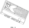
- FIG. 7 to FIG. 8 show another preferred embodiment of this utility model.
- FIG. 7 is a top view
- FIG. 8 is a three-dimensional view.
- the embodiment shown in FIG. 7 to FIG. 8 is different from the embodiment shown in FIG. 1 to FIG. 3 mainly in that heat-dissipation flow-guiding devices 230 are integral extension parts of heat-dissipation fins 240.
- a heat-dissipation device 200 includes an airflow channel 220.
- the airflow channel 220 is defined by a bottom wall 222, two side walls 224, and a top wall (not shown).
- a fan 210, a plurality of heat-dissipation flow-guiding devices 230, and a plurality of heat-dissipation fins 240 are arranged in the airflow channel 220.
- the heat-dissipation flow-guiding devices 230 are integral extension parts of the heat-dissipation fins.
- the parts within the dashed frame are the heat-dissipation flow-guiding devices 230, and the parts outside the dashed frame are the heat-dissipation fins 240.
- An airflow from the fan 210 flows approximately along a longitudinal direction A of the airflow channel 220, and flows through the plurality of heat-dissipation flow-guiding devices 230 and the plurality of heat-dissipation fins 240 in sequence, and takes away the heat of the heat-dissipation flow-guiding devices 230 and the heat-dissipation fins 240, thus achieving heat dissipation.
- the plurality of heat-dissipation fins 240 include seven heat-dissipation fins arranged in parallel.
- the seven heat-dissipation fins extend along the longitudinal direction of the airflow channel 220, and are evenly spaced apart from each other and apart from corresponding side walls.
- the seven heat-dissipation fins are symmetrically distributed horizontally.
- the plurality of heat-dissipation flow-guiding devices 230 are integral extension parts of the plurality of heat-dissipation fins 240.
- the plurality of heat-dissipation flow-guiding devices 230 include seven heat-dissipation flow-guiding fins integrally extending from the seven heat-dissipation fins.
- the heat-dissipation flow-guiding fin 230a is an integral extension part of the heat-dissipation fin 240a
- the heat-dissipation flow-guiding fin 230b is an integral extension part of the heat-dissipation fin 240b
- the heat-dissipation flow-guiding fin 230c is an integral extension part of the heat-dissipation fin 240c
- the heat-dissipation flow-guiding fin 230d is an integral extension part of the heat-dissipation fin 240d.
- the length of the heat-dissipation flow-guiding fin 230a in the central position of the airflow channel 220 is the longest, followed by the length of the heat-dissipation flow-guiding fin 230b and the length of the heat-dissipation flow-guiding fin 230c, and the length of the heat-dissipation flow-guiding fin 230d is the shortest.
- the longitudinal distance between the heat-dissipation flow-guiding fin 230d and the fan 210 is the greatest, followed by the longitudinal distance between the heat-dissipation flow-guiding fin 230c and the fan 210 and the longitudinal distance between the heat-dissipation flow-guiding fin 230b and the fan 210, and the longitudinal distance between the heat-dissipation flow-guiding fin 230a and the fan 210 is the shortest.
- the inventor of this utility model has found that when the heat-dissipation flow-guiding device of this utility model is absent, the airflow from the fan mainly passes through the central position of the airflow channel, that is, the wind speed at two sides of the heat-dissipation fin 240a is maximum, while the wind speed between the heat-dissipation fin 240d and the side wall is very small.
- the lengths of the heat-dissipation flow-guiding fins are descending in a direction from the central position of the airflow channel 220 to two sides. Therefore, an isosceles triangle shape is formed by front ends of the seven heat-dissipation flow-guiding fins, and the vertex of the triangle faces the fan 210.
- the configuration of the heat-dissipation flow-guiding fins is conducive to guiding the airflow from the central position of the airflow channel 220 to two sides.
- the airflow originally concentrated in the central position of the airflow channel 120 is dispersed by the heat-dissipation flow-guiding fins and passes more evenly between the heat-dissipation fins, thus improving the heat dissipation efficiency.
- the inventor of this utility model uses fluid mechanics software to carry out numerical simulation on the embodiment shown in FIG. 7 to FIG. 8 and a comparative embodiment.
- the comparative embodiment is basically similar to the embodiment shown in FIG. 7 to FIG. 8 , with the only difference that the comparative embodiment does not include the inclined side wall 224b (that is, the side wall 224a is at a right angle with the side wall 224c) and the heat-dissipation flow-guiding device 230. That is, the front ends of the heat-dissipation fins are aligned to each other in the comparative embodiment. Please refer to Table 2 for the results of numerical simulation.
- Position 1 is between heat-dissipation fins 240a and 240b
- Position 2 is between heat-dissipation fins 240b and 240c
- Position 3 is between heat-dissipation fins 240c and 240d
- Position 4 is between the heat-dissipation fin 240d and the side wall.
- Table 2 Position 1 Position 2 Position 3 Position 4 Average Comparative embodiment 2.18 m/s 1.72 m/s 0.039 m/s 0.177 m/s 1.03 m/s
- Embodiment 2 2.35 m/s 1.79 m/s 1.16 m/s 0.67 m/s 1.49 m/s
- the airflow velocities in the embodiment of FIG. 7 to FIG. 8 are descending from Position 1 to Position 4, but the rate of decline is much lower than rate of decline in the comparative embodiment.
- the airflow velocity in Position 4 of FIG. 7 to FIG. 8 is 1/4 greater than the airflow velocity in Position 1, while the airflow velocity in Position 4 is less than 1/10 of the airflow velocity in Position 1 in the comparative embodiment. Therefore, compared with the comparative embodiment, the airflow in the entire airflow channel 120 in the embodiment of FIG. 7 to FIG. 8 is more even.
- the average velocity in Positions 1-4 in the embodiment of FIG. 7 to FIG. 8 is 1.49 m/s, while the average velocity in Positions 1-4 in the comparative embodiment is 1.03 m/s. Therefore, the average airflow velocity in the entire airflow channel in Embodiment 1 is greater, and the heat dissipation effect is also better.
- the heat-dissipation flow-guiding devices 230 are integral extension parts of the heat-dissipation fins 240, but this utility model is not limited thereto.
- the heat-dissipation flow-guiding devices 230 and the heat-dissipation fins 240 may be individual parts separated from each other.
- the fan is used as the airflow source in this utility model, but this utility model is not limited thereto.
- any suitable airflow source can be used in this utility model as long as it does not depart from the essence and scope of this utility model.
- the heat-dissipation flow-guiding devices 130 and 230 of this utility model can make the airflow from the fan reach the heat-dissipation fins 140 and 240 more evenly, thus improving the heat dissipation efficiency.
- the heat-dissipation flow-guiding devices 130 and 230 are also heat-dissipation devices, for example, the heat-dissipation flow-guiding device 130 is an array of heat-dissipation flow-guiding columns, and the heat-dissipation flow-guiding device 230 is an integral extension part of the heat-dissipation fin 240, the heat-dissipation flow-guiding device in this utility model can further improve the heat dissipation efficiency.
- a plurality of heat-dissipation flow-guiding column rows of the heat-dissipation flow-guiding device 130 are spaced apart from each other transversely, and the heat-dissipation fins of the heat-dissipation flow-guiding device 230 are also spaced apart from each other transversely; therefore, the heat-dissipation flow-guiding device in this utility model basically may not increase wind resistance.
Landscapes
- Engineering & Computer Science (AREA)
- Physics & Mathematics (AREA)
- Microelectronics & Electronic Packaging (AREA)
- Thermal Sciences (AREA)
- General Engineering & Computer Science (AREA)
- Mechanical Engineering (AREA)
- Theoretical Computer Science (AREA)
- General Physics & Mathematics (AREA)
- Human Computer Interaction (AREA)
- Cooling Or The Like Of Electrical Apparatus (AREA)
- Cooling Or The Like Of Semiconductors Or Solid State Devices (AREA)
- Structures Of Non-Positive Displacement Pumps (AREA)
Abstract
Description
- This utility model relates to a heat-dissipation device for an electronic device. This utility model further relates to an electronic device including the heat-dissipation device.
- With the integration and miniaturization of electronic circuits in electronic devices, the heat release of the electronic circuits per unit volume is increasing, so the heat dissipation problem of the electronic devices is becoming increasingly important. In order to improve the heat dissipation effect, a fan and a set of heat-dissipation fins are arranged in an airflow channel in an existing heat-dissipation device. An airflow from the fan flows along the airflow channel and flows over the surfaces of the heat-dissipation fins to remove heat from the surfaces of the heat-dissipation fins, thus achieving heat dissipation. However, the inventor of this utility model finds that in such a heat-dissipation device, the airflow flowing through the set of heat-dissipation fins is usually uneven, and the velocity of the airflow flowing through the heat-dissipation fins in a central position of the airflow channel is much greater than the velocity of the airflow flowing through the heat-dissipation fins on two sides, which greatly affects the heat dissipation efficiency of the heat-dissipation device.
- Therefore, there is a need for a heat-dissipation device that can allow the airflow to evenly flow through the heat-dissipation fins, thus improving the heat dissipation efficiency. At the same time, the heat-dissipation device is also required to have a simple structure and basically does not increase airflow resistance.
- A heat-dissipation device for an electronic device is provided in this utility model, comprising:
- an airflow channel;
- an airflow source located in the airflow channel;
- a plurality of elongated heat-dissipation fins arranged in the airflow channel; and
- a plurality of heat-dissipation flow-guiding devices arranged in the airflow channel and between the airflow source and the plurality of elongated heat-dissipation fins, wherein the plurality of heat-dissipation flow-guiding devices include a first heat-dissipation flow-guiding device in a central position of the airflow channel and a second heat-dissipation flow-guiding device on two sides of the airflow channel, and a longitudinal distance between the first heat-dissipation flow-guiding device and the airflow source is less than the distance between the second heat-dissipation flow-guiding device and the airflow source.
- Optionally, the plurality of elongated heat-dissipation fins extend along a longitudinal direction of the airflow channel respectively and are spaced apart from each other in a transverse direction perpendicular to the longitudinal direction of the airflow channel, and the plurality of heat-dissipation flow-guiding devices are spaced apart from each other in the transverse direction perpendicular to the longitudinal direction of the airflow channel.
- Optionally, the plurality of heat-dissipation flow-guiding devices further include a third heat-dissipation flow-guiding device between the first heat-dissipation flow-guiding device and the second heat-dissipation flow-guiding device, and a longitudinal distance between the third heat-dissipation flow-guiding device and the airflow source is greater than the distance between the first heat-dissipation flow-guiding device and the airflow source and less than the distance between the second heat-dissipation flow-guiding device and the airflow source.
- Optionally, the first heat-dissipation flow-guiding device includes one or more first heat-dissipation flow-guiding column rows, the second heat-dissipation flow-guiding device includes one or more second heat-dissipation flow-guiding column rows, and the third heat-dissipation flow-guiding device includes one or more third heat-dissipation flow-guiding column rows.
- Optionally, the number of heat-dissipation flow-guiding columns of each third heat-dissipation flow-guiding column row is less than the number of heat-dissipation flow-guiding columns of each first heat-dissipation flow-guiding column row and greater than the number of heat-dissipation flow-guiding columns of each second heat-dissipation flow-guiding column row.
- Optionally, in a direction from the center of the airflow channel to the two sides, the number of the heat-dissipation flow-guiding columns of each heat-dissipation flow-guiding column row in the first heat-dissipation flow-guiding column rows, the second heat-dissipation flow-guiding column rows and the third heat-dissipation flow-guiding column rows is descending.
- Optionally, the cross-section shape of each heat-dissipation flow-guiding column is selected from a rectangle, a circle, an oval, a diamond, or a triangle.
- Optionally, the plurality of elongated heat-dissipation fins are parallel to each other.
- Optionally, the airflow channel is defined by a bottom wall, two side walls and a top wall, and in the transverse direction perpendicular to the longitudinal direction of the airflow channel, each heat-dissipation flow-guiding column row is located between corresponding two adjacent elongated heat-dissipation fins or between the corresponding outermost elongated heat-dissipation fin and the corresponding side wall.
- Optionally, the airflow channel is defined by a bottom wall, two side walls and a top wall, and in the transverse direction perpendicular to the longitudinal direction of the airflow channel, each heat-dissipation flow-guiding column row is centrally located between corresponding two adjacent elongated heat-dissipation fins or centrally located between the outermost elongated heat-dissipation fin and the corresponding side wall.
- Optionally, at least some heat-dissipation flow-guiding columns in each heat-dissipation flow-guiding column row of the first heat-dissipation flow-guiding device, the second heat-dissipation flow-guiding device and the third heat-dissipation flow-guiding device are aligned to corresponding heat-dissipation flow-guiding columns in another heat-dissipation flow-guiding column row.
- Optionally, the heat-dissipation flow-guiding device is an integral extension part of the plurality of elongated heat-dissipation fins.
- Optionally, the plurality of elongated heat-dissipation fins are parallel to each other, and longitudinal distances between the heat-dissipation flow-guiding devices and the airflow source are ascending in a direction from the center of the airflow channel to the two sides.
- Optionally, the plurality of heat-dissipation flow-guiding devices are made of aluminum or steel.
- Optionally, the airflow source is a fan.
- Optionally, the airflow channel is defined by a bottom wall, two side walls and a top wall, and the side walls include an inclined sidewall portion extending outward in an airflow direction of the airflow channel and located downstream of the airflow source.
- In another aspect of this utility model, an electronic device is provided, comprising the heat-dissipation device for an electronic device as described in the foregoing and an electronic component in thermal communication with the heat-dissipation device.
-
-
FIG. 1 is a top view of the heat-dissipation device according to a preferred embodiment of this utility model; -
FIG. 2 is a three-dimensional view of the heat-dissipation device shown inFIG. 1 ; -
FIG. 3 is an enlarged view of a part of the heat-dissipation device shown inFIG. 1 ; -
FIG. 4 is optional shapes of a heat-dissipation flow-guiding column according to this utility model; -
FIG. 5 is a simulation result of numerical simulation of a comparative embodiment using fluid dynamics software; -
FIG. 6 is a simulation result of numerical simulation of the embodiment inFIG. 1 to FIG. 3 using fluid dynamics software; -
FIG. 7 is a top view of a heat-dissipation device according to another preferred embodiment of this utility model; and -
FIG. 8 is a three-dimensional view of the heat-dissipation device shown inFIG. 7 . - Embodiments of this utility model are described in detail below, and examples of the embodiments are shown in the accompanying drawings. Identical or similar reference numerals throughout this text represent identical or similar elements or elements having identical or similar functions. The embodiments described below with reference to the accompanying drawings are exemplary, are only used to explain this utility model, and cannot be construed as limitations to this utility model.
- Unless otherwise defined, technical or scientific terms used here shall be of general meanings understood by those of ordinary skill in the field to which this utility model belongs. In the description of this utility model, it is appreciated that orientation or position relations indicated by the terms "center," "longitudinal," "transverse," "upper," "lower," "front," "rear," "left," "right," "vertical," "horizontal," "top," "bottom," "inside," "outside" and so on are orientation or position relations shown based on the accompanying drawings, which are only intended to facilitate the description of this utility model and simplify the description, rather than indicate or imply that the device or element referred to must have a specific orientation or be constructed and operated in the specific orientation, and thus cannot be construed as limitations to this utility model. In addition, the terms "first" and "second" are used only for description and cannot be construed as indicating or implying relative importance.
-
FIG. 1 to FIG. 3 are schematic views showing a heat-dissipation device 100 according to an embodiment of this utility model.FIG. 1 is a top view,FIG. 2 is a three-dimensional view, andFIG. 3 is an enlarged view of a part ofFIG. 1 . As shown inFIG. 1 , the heat-dissipation device 100 includes anairflow channel 120. Theairflow channel 120 is defined by abottom wall 122, twoside walls 124, and a top wall (not shown). Afan 110, a plurality of heat-dissipation flow-guidingdevices 130, and a plurality of heat-dissipation fins 140 are arranged in theairflow channel 120. An airflow from thefan 110 flows approximately along a longitudinal direction A of theairflow channel 120, and flows through the plurality of heat-dissipation flow-guidingdevices 130 and the plurality of heat-dissipation fins 140 in sequence, and takes away the heat of the heat-dissipation flow-guidingdevices 130 and the heat-dissipation fins 140, thus achieving heat dissipation. - As shown in
FIG. 3 , the plurality of heat-dissipation fins 140 include seven heat-dissipation fins arranged in parallel. The seven heat-dissipation fins extend along the longitudinal direction of theairflow channel 120 are aligned to each other, and are evenly spaced apart from each other and apart from corresponding side walls. The plurality of heat-dissipation flow-guidingdevices 130 include eight heat-dissipation flow-guiding column rows. The eight heat-dissipation flow-guiding column rows are symmetrically distributed horizontally. In order to save space, the four upper heat-dissipation flow-guiding column rows are mainly described here. The plurality of heat-dissipation flow-guidingdevices 130 include two heat-dissipation flow-guidingcolumn rows column row 132 or a first heat-dissipation flow-guiding device 132) in central positions of the airflow channel 120 (farthest from the side wall 124), a heat-dissipation flow-guiding column row 136 (or referred to as a second heat-dissipation flow-guiding device 136) in a position on two sides of the airflow channel 120 (adjacent to the side wall 124), and two heat-dissipation flow-guiding column rows 134 (or collectively referred to as heat-dissipation flow-guidingcolumns 134 or a third heat-dissipation flow-guiding device 134) between the heat-dissipation flow-guidingcolumn rows column row 136. As shown in the figure, in the transverse direction perpendicular to the longitudinal direction of the airflow channel, each heat-dissipation flow-guiding column row is located between corresponding two adjacent elongated heat-dissipation fins or between the corresponding outermost elongated heat-dissipation fin and the corresponding side wall. For example, in the transverse direction, the heat-dissipation flow-guidingcolumn row 132b is located between heat-dissipation fins 140a and 140b, the heat-dissipation flow-guidingcolumn row 134a is located between heat-dissipation fins 140b and 140c, the heat-dissipation flow-guidingcolumn row 134b is located between heat-dissipation fins 140c and 140d, and the heat-dissipation flow-guidingcolumn row 136 is located between the heat-dissipation fin 140d and thecorresponding side wall 124. In a preferred embodiment shown inFIG. 3 , in the transverse direction, the heat-dissipation flow-guidingcolumn row 132b is centrally located between heat-dissipation fins 140a and 140b, the heat-dissipation flow-guidingcolumn row 134a is centrally located between heat-dissipation fins 140b and 140c, the heat-dissipation flow-guidingcolumn row 134b is centrally located between heat-dissipation fins 140c and 140d, and the heat-dissipation flow-guidingcolumn row 136 is centrally located between the heat-dissipation fin 140d and thecorresponding side wall 124. - As shown in
FIG. 1 andFIG. 3 , in a direction from the central position of theairflow channel 120 to the two sides, the number of the heat-dissipation flow-guiding columns of each heat-dissipation flow-guiding column row is descending. That is, the heat-dissipation flow-guidingcolumn row 132b includes four heat-dissipation flow-guiding columns, the heat-dissipation flow-guidingcolumn row 134a includes three heat-dissipation flow-guiding columns, the heat-dissipation flow-guidingcolumn row 134b includes two heat-dissipation flow-guiding columns, and the heat-dissipation flow-guidingcolumn row 136 includes one heat-dissipation flow-guiding column. The corresponding heat-dissipation flow-guiding columns in each heat-dissipation flow-guiding column row are aligned to each other in the transverse direction. That is, the first heat-dissipation flow-guiding columns (heat-dissipation flow-guiding columns that are closest to the heat-dissipation fins in the heat-dissipation flow-guiding column rows) in each heat-dissipation flow-guiding column row are aligned to each other (i.e., in identical longitudinal positions), the second heat-dissipation flow-guiding columns (heat-dissipation flow-guiding columns that are second closest to the heat-dissipation fins in the heat-dissipation flow-guiding column rows, if any) in each heat-dissipation flow-guiding column row are aligned to each other, and so on. Therefore, longitudinal distances between the two heat-dissipation flow-guidingcolumn rows column 132 or first heat-dissipation flow-guiding device 132) in the central positions of the airflow channel and thefan 110 are the shortest. In a direction from the center of the airflow channel to the two sides, the longitudinal distances between the heat-dissipation flow-guiding column rows and the fan are ascending. - The inventor of this utility model has found that when the heat-dissipation flow-guiding
device 130 of this utility model is absent, the airflow from the fan mainly passes through the central position of the airflow channel, that is, the wind speed on two sides of the heat-dissipation fin 140a is maximum, while the wind speed between the heat-dissipation fin 140d and the side wall is very small. As described above, the longitudinal distances between the two heat-dissipation flow-guidingcolumn rows fan 110 first encounters the heat-dissipation flow-guidingcolumn rows column row 132b is located between the heat-dissipation fins dissipation fins column row 134a is located between the heat-dissipation fins dissipation fins fan 110 to the heat-dissipation fins column row 132b, and a part of the airflow on the flow path is deflected by the heat-dissipation flow-guidingcolumn row 132b to a side of the airflow channel. After that, an airflow on a flow path from thefan 110 to the heat-dissipation fins column row 132b encounter the heat-dissipation flow-guidingcolumn row 134a, and a part of them is deflected by the heat-dissipation flow-guidingcolumn row 134a to a side of the airflow channel. As such, the airflow originally concentrated in the central position of theairflow channel 120 is dispersed by the heat-dissipation flow-guiding column rows and passes more evenly through the heat-dissipation fins, thus improving the heat dissipation efficiency. - In general, the longitudinal distances between the heat-dissipation flow-guiding column rows and the fan are ascending in the direction from the center of the airflow channel to the two sides. Therefore, as shown in
FIG. 3 , all heat-dissipation flow-guiding columns assume an isosceles triangle as a whole, and the vertex of the isosceles triangle faces thefan 110. As shown inFIG. 1 , two inclined sides of the isosceles triangle, together with theinclined side wall 124b, are conducive to guiding the airflow from the central position of the airflow channel to the two sides, so that the airflow passes more evenly through the heat-dissipation fins, thus improving the heat dissipation efficiency. - In order to verify the technical effect of this utility model, the inventor of this utility model uses fluid mechanics software to carry out numerical simulation on the embodiment shown in
FIG. 1 to FIG. 3 and a comparative embodiment. The comparative embodiment is basically similar to the embodiment shown inFIG. 1 to FIG. 3 , with the only difference that the comparative embodiment does not include theinclined side wall 124b (that is, theside wall 124a is at a right angle with theside wall 124c) and the heat-dissipation flow-guiding device 30 (correspondingly, compared with the embodiment inFIG. 1 to FIG. 3 , the heat-dissipation fins of the comparative embodiment extend longer towards the direction of thefan 110 to at least partially replace blank positions left by the heat-dissipation flow-guiding device 130).FIG. 6 is a result of simulation carried out in the embodiment shown inFIG. 1 to FIG. 3 , andFIG. 5 is a result of simulation carried out in the comparative embodiment. Please refer to Table 1 for the result of simulation. Position 1 is between the heat-dissipation fins dissipation fins dissipation fins dissipation fin 140d and the side wall.Table 1 Velocity in Position 1 Velocity in Position 2 Velocity in Position 3 Velocity in Position 4 Average velocity Comparative embodiment 2.18 m/s 1.72 m/s 0.039 m/s 0.177 m/s 1.03 m/s Embodiment 1 2.13 m/s 2.13 m/s 1.15 m/s 0.764 m/s 1.54 m/s - As shown in Table 1, in Embodiment 1, the airflow velocities in Position 1 and Position 2 are identical, both of which are 2.13 m/s, while in the comparative embodiment, the airflow velocity in Position 1 is maximum, and the airflow velocity in Position 2 is evidently lower than the airflow velocity in Position 1. In addition, in Embodiment 1, the airflow velocity in Position 4 is about 1/3 of that in Position 1, while in the comparative embodiment, the airflow velocity in Position 4 is less than 1/10 of that in Position 1. Therefore, compared with the comparative embodiment, the airflow in the
entire airflow channel 120 is more even in Embodiment 1. - In addition, the average velocity of Positions 1-4 in Embodiment 1 is 1.54m /s, while the average velocity of Positions 1-4 in the comparative embodiment is 1.03 m/s. Therefore, the average airflow velocity of the entire airflow channel in Embodiment 1 is greater, and a better heat dissipation effect is also achieved.
-
FIG. 1 to FIG. 3 show a preferred embodiment of this utility model. However, this utility model is not limited thereto. For example, a fan is used in the embodiment shown inFIG. 1 to FIG. 3 , but this utility model is not limited thereto. In an optional embodiment, any suitable airflow source can be used in this utility model. - In the embodiment shown in
FIG. 1 to FIG. 3 , the cross section of the heat-dissipation flow-guiding column is rectangular, but this utility model is not limited thereto. The cross section of the heat-dissipation flow-guiding column of this utility model may be in any suitable shape, for example, a circle, a square, an oval, a diamond, and a triangle as shown inFIG. 4 . - In the embodiment shown in
FIG. 1 to FIG. 3 , seven heat-dissipation fins and eight heat-dissipation flow-guiding column rows are included, but this utility model is not limited thereto. In an optional embodiment, this utility model may include any suitable number of heat-dissipation fins and heat-dissipation flow-guiding column rows. - In the embodiment shown in
FIG. 1 to FIG. 3 , the shape of each heat-dissipation flow-guiding column is basically the same, and the spacing between the heat-dissipation flow-guiding column rows and the spacing between the heat-dissipation flow-guiding columns in each heat-dissipation flow-guiding column row are basically the same, but this utility model is not limited thereto. In an optional embodiment, the shapes of the heat-dissipation flow-guiding columns may be different, the spacing between the heat-dissipation flow-guiding column rows may be different, and/or the spacing between the heat-dissipation flow-guiding columns in each heat-dissipation flow-guiding column row may be different. - In the embodiment shown in
FIG. 1 to FIG. 3 , the heat-dissipation flow-guiding columns of each heat-dissipation flow-guiding column row are basically aligned along a longitudinal direction of the airflow channel, but this utility model is not limited thereto. In an optional embodiment, heat-dissipation flow-guiding columns of at least part of the heat-dissipation flow-guiding column rows are not aligned along the longitudinal direction of the airflow channel. - In the embodiment shown in
FIG. 1 to FIG. 3 , the heat-dissipation flow-guiding column rows each include a plurality of heat-dissipation flow-guiding columns, but this utility model is not limited thereto. In an optional embodiment, at least part of adjacent heat-dissipation flow-guiding columns in at least one heat-dissipation flow-guiding column row may be connected together to form a whole. -
FIG. 7 to FIG. 8 show another preferred embodiment of this utility model.FIG. 7 is a top view, andFIG. 8 is a three-dimensional view. The embodiment shown inFIG. 7 to FIG. 8 is different from the embodiment shown inFIG. 1 to FIG. 3 mainly in that heat-dissipation flow-guidingdevices 230 are integral extension parts of heat-dissipation fins 240. - As shown in
FIG. 7 , a heat-dissipation device 200 includes anairflow channel 220. Theairflow channel 220 is defined by abottom wall 222, twoside walls 224, and a top wall (not shown). Afan 210, a plurality of heat-dissipation flow-guidingdevices 230, and a plurality of heat-dissipation fins 240 are arranged in theairflow channel 220. In this embodiment, the heat-dissipation flow-guidingdevices 230 are integral extension parts of the heat-dissipation fins. The parts within the dashed frame are the heat-dissipation flow-guidingdevices 230, and the parts outside the dashed frame are the heat-dissipation fins 240. An airflow from thefan 210 flows approximately along a longitudinal direction A of theairflow channel 220, and flows through the plurality of heat-dissipation flow-guidingdevices 230 and the plurality of heat-dissipation fins 240 in sequence, and takes away the heat of the heat-dissipation flow-guidingdevices 230 and the heat-dissipation fins 240, thus achieving heat dissipation. - As shown in the figures, the plurality of heat-
dissipation fins 240 include seven heat-dissipation fins arranged in parallel. The seven heat-dissipation fins extend along the longitudinal direction of theairflow channel 220, and are evenly spaced apart from each other and apart from corresponding side walls. The seven heat-dissipation fins are symmetrically distributed horizontally. In order to save space, the four heat-dissipation flow-guiding column rows above are mainly described here. The plurality of heat-dissipation flow-guidingdevices 230 are integral extension parts of the plurality of heat-dissipation fins 240. As shown in the figures, the plurality of heat-dissipation flow-guidingdevices 230 include seven heat-dissipation flow-guiding fins integrally extending from the seven heat-dissipation fins. The heat-dissipation flow-guidingfin 230a is an integral extension part of the heat-dissipation fin 240a, the heat-dissipation flow-guidingfin 230b is an integral extension part of the heat-dissipation fin 240b, the heat-dissipation flow-guidingfin 230c is an integral extension part of the heat-dissipation fin 240c, and the heat-dissipation flow-guidingfin 230d is an integral extension part of the heat-dissipation fin 240d. - As shown in
FIG. 7 andFIG. 8 , in a direction from a central position of theairflow channel 220 to two sides, lengths of the heat-dissipation flow-guiding fins are descending and longitudinal distances between them and thefan 210 are ascending. That is, the length of the heat-dissipation flow-guidingfin 230a in the central position of theairflow channel 220 is the longest, followed by the length of the heat-dissipation flow-guidingfin 230b and the length of the heat-dissipation flow-guidingfin 230c, and the length of the heat-dissipation flow-guidingfin 230d is the shortest. The longitudinal distance between the heat-dissipation flow-guidingfin 230d and thefan 210 is the greatest, followed by the longitudinal distance between the heat-dissipation flow-guidingfin 230c and thefan 210 and the longitudinal distance between the heat-dissipation flow-guidingfin 230b and thefan 210, and the longitudinal distance between the heat-dissipation flow-guidingfin 230a and thefan 210 is the shortest. - The inventor of this utility model has found that when the heat-dissipation flow-guiding device of this utility model is absent, the airflow from the fan mainly passes through the central position of the airflow channel, that is, the wind speed at two sides of the heat-
dissipation fin 240a is maximum, while the wind speed between the heat-dissipation fin 240d and the side wall is very small. - As described above, the lengths of the heat-dissipation flow-guiding fins are descending in a direction from the central position of the
airflow channel 220 to two sides. Therefore, an isosceles triangle shape is formed by front ends of the seven heat-dissipation flow-guiding fins, and the vertex of the triangle faces thefan 210. The configuration of the heat-dissipation flow-guiding fins is conducive to guiding the airflow from the central position of theairflow channel 220 to two sides. As such, the airflow originally concentrated in the central position of theairflow channel 120 is dispersed by the heat-dissipation flow-guiding fins and passes more evenly between the heat-dissipation fins, thus improving the heat dissipation efficiency. - In order to verify the technical effect of this utility model, the inventor of this utility model uses fluid mechanics software to carry out numerical simulation on the embodiment shown in
FIG. 7 to FIG. 8 and a comparative embodiment. The comparative embodiment is basically similar to the embodiment shown inFIG. 7 to FIG. 8 , with the only difference that the comparative embodiment does not include theinclined side wall 224b (that is, theside wall 224a is at a right angle with theside wall 224c) and the heat-dissipation flow-guidingdevice 230. That is, the front ends of the heat-dissipation fins are aligned to each other in the comparative embodiment. Please refer to Table 2 for the results of numerical simulation. Position 1 is between heat-dissipation fins dissipation fins dissipation fins dissipation fin 240d and the side wall.Table 2 Position 1 Position 2 Position 3 Position 4 Average Comparative embodiment 2.18 m/s 1.72 m/s 0.039 m/s 0.177 m/s 1.03 m/s Embodiment 2 2.35 m/s 1.79 m/s 1.16 m/s 0.67 m/s 1.49 m/s - As shown in Table 2, the airflow velocities in the embodiment of
FIG. 7 to FIG. 8 are descending from Position 1 to Position 4, but the rate of decline is much lower than rate of decline in the comparative embodiment. As shown in the figures, the airflow velocity in Position 4 ofFIG. 7 to FIG. 8 is 1/4 greater than the airflow velocity in Position 1, while the airflow velocity in Position 4 is less than 1/10 of the airflow velocity in Position 1 in the comparative embodiment. Therefore, compared with the comparative embodiment, the airflow in theentire airflow channel 120 in the embodiment ofFIG. 7 to FIG. 8 is more even. - In addition, the average velocity in Positions 1-4 in the embodiment of
FIG. 7 to FIG. 8 is 1.49 m/s, while the average velocity in Positions 1-4 in the comparative embodiment is 1.03 m/s. Therefore, the average airflow velocity in the entire airflow channel in Embodiment 1 is greater, and the heat dissipation effect is also better. - In the embodiment of
FIG. 7 to FIG. 8 , the heat-dissipation flow-guidingdevices 230 are integral extension parts of the heat-dissipation fins 240, but this utility model is not limited thereto. In an optional embodiment, the heat-dissipation flow-guidingdevices 230 and the heat-dissipation fins 240 may be individual parts separated from each other. - In the embodiments shown in
FIG. 1 to FIG. 3 andFIG. 7 to FIG. 8 , the fan is used as the airflow source in this utility model, but this utility model is not limited thereto. In an optional embodiment, any suitable airflow source can be used in this utility model as long as it does not depart from the essence and scope of this utility model. - As described above, the heat-dissipation flow-guiding
devices dissipation fins devices device 130 is an array of heat-dissipation flow-guiding columns, and the heat-dissipation flow-guidingdevice 230 is an integral extension part of the heat-dissipation fin 240, the heat-dissipation flow-guiding device in this utility model can further improve the heat dissipation efficiency. In addition, a plurality of heat-dissipation flow-guiding column rows of the heat-dissipation flow-guidingdevice 130 are spaced apart from each other transversely, and the heat-dissipation fins of the heat-dissipation flow-guidingdevice 230 are also spaced apart from each other transversely; therefore, the heat-dissipation flow-guiding device in this utility model basically may not increase wind resistance. - The exemplary embodiments described above are only used to illustrate the principles of this utility model and are not intended to limit the protection scope of this utility model. Those of ordinary skill in the art can make various variations and improvements without departing from the spirit and essence of this utility model. These variations and improvements also fall within the protection scope of this utility model.
Claims (15)
- A heat-dissipation device for an electronic device, characterised in that it comprises:an airflow channel;an airflow source located in the airflow channel;a plurality of elongated heat-dissipation fins arranged in the airflow channel; anda plurality of heat-dissipation flow-guiding devices arranged in the airflow channel and between the airflow source and the plurality of elongated heat-dissipation fins, wherein the plurality of heat-dissipation flow-guiding devices comprise a first heat-dissipation flow-guiding device in a central position of the airflow channel and a second heat-dissipation flow-guiding device on two sides of the airflow channel, and a longitudinal distance between the first heat-dissipation flow-guiding device and the airflow source is less than the distance between the second heat-dissipation flow-guiding device and the airflow source.
- The heat-dissipation device for an electronic device of claim 1, characterised in that the plurality of elongated heat-dissipation fins extend along a longitudinal direction of the airflow channel respectively and are spaced apart from each other in a transverse direction perpendicular to the longitudinal direction of the airflow channel, and the plurality of heat-dissipation flow-guiding devices are spaced apart from each other in the transverse direction perpendicular to the longitudinal direction of the airflow channel.
- The heat-dissipation device for an electronic device of claim 1, characterised in that the plurality of heat-dissipation flow-guiding devices further comprise a third heat-dissipation flow-guiding device between the first heat-dissipation flow-guiding device and the second heat-dissipation flow-guiding device, and a longitudinal distance between the third heat-dissipation flow-guiding device and the airflow source is greater than the distance between the first heat-dissipation flow-guiding device and the airflow source and less than the distance between the second heat-dissipation flow-guiding device and the airflow source.
- The heat-dissipation device for an electronic device of claim 3, characterised in that the first heat-dissipation flow-guiding device comprises one or more first heat-dissipation flow-guiding column rows, the second heat-dissipation flow-guiding device comprises one or more second heat-dissipation flow-guiding column rows, and the third heat-dissipation flow-guiding device comprises one or more third heat-dissipation flow-guiding column rows.
- The heat-dissipation device for an electronic device of claim 4, characterised in that the number of heat-dissipation flow-guiding columns of each third heat-dissipation flow-guiding column row is less than the number of heat-dissipation flow-guiding columns of each first heat-dissipation flow-guiding column row and greater than the number of heat-dissipation flow-guiding columns of each second heat-dissipation flow-guiding column row.
- The heat-dissipation device for an electronic device of claim 5, characterised in that in a direction from the center of the airflow channel to the two sides, the number of the heat-dissipation flow-guiding columns of each heat-dissipation flow-guiding column row in the first heat-dissipation flow-guiding column rows, the second heat-dissipation flow-guiding column rows, and the third heat-dissipation flow-guiding column rows is descending.
- The heat-dissipation device for an electronic device of claim 5, characterised in that the cross-section shape of each heat-dissipation flow-guiding column is selected from a rectangle, a circle, an oval, a diamond, or a triangle.
- The heat-dissipation device for an electronic device of any of claims 5 to 7, characterised in that the plurality of elongated heat-dissipation fins are parallel to each other.
- The heat-dissipation device for an electronic device of claim 8, characterised in that the airflow channel is defined by a bottom wall, two side walls and a top wall, and in the transverse direction perpendicular to the longitudinal direction of the airflow channel, each heat-dissipation flow-guiding column row is located between corresponding two adjacent elongated heat-dissipation fins or between the corresponding outermost elongated heat-dissipation fin and the corresponding side wall.
- The heat-dissipation device for an electronic device of claim 8, characterised in that the airflow channel is defined by a bottom wall, two side walls and a top wall, and in the transverse direction perpendicular to the longitudinal direction of the airflow channel, each heat-dissipation flow-guiding column row is centrally located between corresponding two adjacent elongated heat-dissipation fins or centrally located between the outermost elongated heat-dissipation fin and the corresponding side wall.
- The heat-dissipation device for an electronic device of claim 9, characterised in that at least some heat-dissipation flow-guiding columns in each heat-dissipation flow-guiding column row of the first heat-dissipation flow-guiding device, the second heat-dissipation flow-guiding device and the third heat-dissipation flow-guiding device are aligned to corresponding heat-dissipation flow-guiding columns in another heat-dissipation flow-guiding column row.
- The heat-dissipation device for an electronic device of any of claims 1 to 3, characterised in that the heat-dissipation flow-guiding device is an integral extension part of the plurality of elongated heat-dissipation fins.
- The heat-dissipation device for an electronic device of claim 12, characterised in that the plurality of elongated heat-dissipation fins are parallel to each other, and longitudinal distances between the heat-dissipation flow-guiding devices and the airflow source are ascending in a direction from the center of the airflow channel to the two sides.
- The heat-dissipation device for an electronic device of any of claims 1 to 3, characterised in that at least one of
the plurality of heat-dissipation flow-guiding devices are made of aluminum or steel;
the airflow source is a fan; and
the airflow channel is defined by a bottom wall, two side walls and a top wall, and the side walls comprise an inclined sidewall portion extending outward in an airflow direction of the airflow channel and located downstream of the airflow source. - An electronic device, characterised by comprising the heat-dissipation device for an electronic device of any of claims 1 to 14 and an electronic component in thermal communication with the heat-dissipation device.
Applications Claiming Priority (1)
| Application Number | Priority Date | Filing Date | Title |
|---|---|---|---|
| CN201820550429.1U CN208227548U (en) | 2018-04-18 | 2018-04-18 | Electronic device and radiator for electronic device |
Publications (2)
| Publication Number | Publication Date |
|---|---|
| EP3561432A1 true EP3561432A1 (en) | 2019-10-30 |
| EP3561432B1 EP3561432B1 (en) | 2022-09-14 |
Family
ID=64529621
Family Applications (1)
| Application Number | Title | Priority Date | Filing Date |
|---|---|---|---|
| EP19168814.2A Active EP3561432B1 (en) | 2018-04-18 | 2019-04-12 | Electronic device and heat-dissipation device for electronic device |
Country Status (4)
| Country | Link |
|---|---|
| US (1) | US10993351B2 (en) |
| EP (1) | EP3561432B1 (en) |
| KR (2) | KR20190121702A (en) |
| CN (1) | CN208227548U (en) |
Cited By (1)
| Publication number | Priority date | Publication date | Assignee | Title |
|---|---|---|---|---|
| CN112954946A (en) * | 2019-11-26 | 2021-06-11 | 杭州海康威视数字技术股份有限公司 | Heat radiation member and electronic device |
Families Citing this family (14)
| Publication number | Priority date | Publication date | Assignee | Title |
|---|---|---|---|---|
| WO2021217366A1 (en) * | 2020-04-27 | 2021-11-04 | 深圳市大疆创新科技有限公司 | Radiator, heat dissipation structure and unmanned aerial vehicle |
| CN112165282B (en) * | 2020-09-29 | 2022-04-05 | 深圳市千里智能控制科技有限公司 | Stepper motor motion controller based on DDS technology |
| EP3992565B1 (en) * | 2020-10-28 | 2024-03-13 | B/E Aerospace, Inc. | Heat exchanger manifold |
| KR102862230B1 (en) * | 2021-01-28 | 2025-09-19 | 엘에스일렉트릭(주) | Heat Sink for Electronic Devices |
| CN113035805A (en) * | 2021-03-04 | 2021-06-25 | 阳光电源股份有限公司 | Liquid cooling plate and power module |
| TWI792253B (en) * | 2021-04-06 | 2023-02-11 | 其陽科技股份有限公司 | Heat dissipation device |
| CN115066139B (en) * | 2021-12-03 | 2023-06-06 | 荣耀终端有限公司 | Heat dissipation module and electronic equipment |
| KR102731252B1 (en) * | 2022-05-11 | 2024-11-15 | 조창희 | Server for converting construction map data |
| KR102564156B1 (en) * | 2022-05-11 | 2023-08-07 | 조창희 | Method and system for civil designing through web |
| KR102731251B1 (en) * | 2022-05-11 | 2024-11-15 | 조창희 | Road environmental cognitive system |
| KR102731253B1 (en) * | 2022-05-11 | 2024-11-15 | 조창희 | System and method for design of i.t.s. facilities using cloud server |
| KR102564154B1 (en) * | 2022-05-11 | 2023-08-07 | 조창희 | Apparatus for scenic road designation |
| US20240074031A1 (en) * | 2022-08-29 | 2024-02-29 | Creeled, Inc. | Textured metal core printed circuit boards for improved thermal dissipation |
| CN115942724B (en) * | 2023-03-15 | 2023-06-30 | 安徽百信信息技术有限公司 | A liquid cooling radiator |
Citations (7)
| Publication number | Priority date | Publication date | Assignee | Title |
|---|---|---|---|---|
| US20040099712A1 (en) * | 2002-11-27 | 2004-05-27 | Tonkovich Anna Lee | Microchannel apparatus, methods of making microchannel apparatus, and processes of conducting unit operations |
| US20040244947A1 (en) * | 2003-05-14 | 2004-12-09 | Inventor Precision Co., Ltd. | Heat sinks for a cooler |
| US20050057899A1 (en) * | 2003-09-16 | 2005-03-17 | Charles Lord | Compact electronics plenum |
| US20060056153A1 (en) * | 2004-09-16 | 2006-03-16 | Industrial Design Laboratories Inc. | Multi-heatsink integrated cooling device |
| US20140342652A1 (en) * | 2012-08-24 | 2014-11-20 | Huawei Technologies Co., Ltd. | Air Cooling System and Electronic Device |
| EP3349555A1 (en) * | 2017-01-13 | 2018-07-18 | Alpine Electronics, Inc. | Electronic apparatus |
| EP3376839A1 (en) * | 2017-03-17 | 2018-09-19 | MAN Truck & Bus AG | Cooling device for electronic control device |
Family Cites Families (20)
| Publication number | Priority date | Publication date | Assignee | Title |
|---|---|---|---|---|
| US4884168A (en) * | 1988-12-14 | 1989-11-28 | Cray Research, Inc. | Cooling plate with interboard connector apertures for circuit board assemblies |
| US5150278A (en) * | 1991-04-16 | 1992-09-22 | J. E. Thomas Specialties Limited | Finned housing |
| US6173758B1 (en) * | 1999-08-02 | 2001-01-16 | General Motors Corporation | Pin fin heat sink and pin fin arrangement therein |
| DE20015931U1 (en) * | 2000-09-14 | 2001-01-04 | Lin, Liken, Tu-Cheng, Taipeh | CPU cooling device |
| JP3690658B2 (en) * | 2001-07-13 | 2005-08-31 | インターナショナル・ビジネス・マシーンズ・コーポレーション | Heat sink, cooling member, semiconductor substrate cooling apparatus, computer, and heat dissipation method |
| KR100767325B1 (en) * | 2001-08-20 | 2007-10-16 | 현대중공업 주식회사 | Power Semiconductor Device Cooling Device for Inverter |
| US20030121645A1 (en) * | 2001-12-28 | 2003-07-03 | Tien-Lai Wang | Heat dissipater for a central processing unit |
| JP4675283B2 (en) * | 2006-06-14 | 2011-04-20 | トヨタ自動車株式会社 | Heat sink and cooler |
| US20080066888A1 (en) * | 2006-09-08 | 2008-03-20 | Danaher Motion Stockholm Ab | Heat sink |
| JP2008140802A (en) * | 2006-11-30 | 2008-06-19 | Fuji Electric Fa Components & Systems Co Ltd | heatsink |
| CN101202528B (en) * | 2006-12-11 | 2012-10-10 | 丹佛斯传动有限公司 | Electronic device and electric motor frequency converter |
| CN101202529A (en) * | 2006-12-11 | 2008-06-18 | 丹佛斯传动有限公司 | Electronic device and motor frequency converter |
| US7760506B1 (en) * | 2007-06-06 | 2010-07-20 | Hewlett-Packard Development Company, L.P. | Electronic components, systems and apparatus with air flow devices |
| US20090145581A1 (en) * | 2007-12-11 | 2009-06-11 | Paul Hoffman | Non-linear fin heat sink |
| TWI377333B (en) * | 2009-02-05 | 2012-11-21 | Wistron Corp | Heat dissipation device |
| CN102356014B (en) * | 2009-03-24 | 2013-06-19 | 住友精密工业株式会社 | Heat sink |
| DE202010011783U1 (en) * | 2010-08-20 | 2010-11-04 | Asia Vital Components Co., Ltd., Hsin Chuan City | Low-pressure thermosiphon coolers driven by pressure gradient |
| US9657997B2 (en) * | 2010-10-27 | 2017-05-23 | Honda Motor Co., Ltd. | Cooling device with cooling passage for liquid refrigerant and juxtaposed fin assembly |
| KR101278313B1 (en) * | 2011-11-04 | 2013-06-25 | 삼성전기주식회사 | Heat sink |
| DE102011118483A1 (en) * | 2011-11-12 | 2013-05-16 | Volkswagen Aktiengesellschaft | Heat exchanger used for motor car, has base whose oriented cross-section is set with different widths and lengths perpendicular and parallel to longitudinal direction such that maximum length has greater extension than maximum width |
-
2018
- 2018-04-18 CN CN201820550429.1U patent/CN208227548U/en active Active
-
2019
- 2019-04-12 EP EP19168814.2A patent/EP3561432B1/en active Active
- 2019-04-16 US US16/386,159 patent/US10993351B2/en active Active
- 2019-04-17 KR KR1020190044788A patent/KR20190121702A/en not_active Ceased
-
2025
- 2025-04-16 KR KR1020250049727A patent/KR20250057742A/en active Pending
Patent Citations (7)
| Publication number | Priority date | Publication date | Assignee | Title |
|---|---|---|---|---|
| US20040099712A1 (en) * | 2002-11-27 | 2004-05-27 | Tonkovich Anna Lee | Microchannel apparatus, methods of making microchannel apparatus, and processes of conducting unit operations |
| US20040244947A1 (en) * | 2003-05-14 | 2004-12-09 | Inventor Precision Co., Ltd. | Heat sinks for a cooler |
| US20050057899A1 (en) * | 2003-09-16 | 2005-03-17 | Charles Lord | Compact electronics plenum |
| US20060056153A1 (en) * | 2004-09-16 | 2006-03-16 | Industrial Design Laboratories Inc. | Multi-heatsink integrated cooling device |
| US20140342652A1 (en) * | 2012-08-24 | 2014-11-20 | Huawei Technologies Co., Ltd. | Air Cooling System and Electronic Device |
| EP3349555A1 (en) * | 2017-01-13 | 2018-07-18 | Alpine Electronics, Inc. | Electronic apparatus |
| EP3376839A1 (en) * | 2017-03-17 | 2018-09-19 | MAN Truck & Bus AG | Cooling device for electronic control device |
Cited By (2)
| Publication number | Priority date | Publication date | Assignee | Title |
|---|---|---|---|---|
| CN112954946A (en) * | 2019-11-26 | 2021-06-11 | 杭州海康威视数字技术股份有限公司 | Heat radiation member and electronic device |
| CN112954946B (en) * | 2019-11-26 | 2022-08-26 | 杭州海康威视数字技术股份有限公司 | Heat radiation member and electronic device |
Also Published As
| Publication number | Publication date |
|---|---|
| EP3561432B1 (en) | 2022-09-14 |
| CN208227548U (en) | 2018-12-11 |
| US20190327854A1 (en) | 2019-10-24 |
| KR20250057742A (en) | 2025-04-29 |
| KR20190121702A (en) | 2019-10-28 |
| US10993351B2 (en) | 2021-04-27 |
Similar Documents
| Publication | Publication Date | Title |
|---|---|---|
| US10993351B2 (en) | One mixed heat sink fins for better thermal dissipation used on electrical products | |
| CN111415915B (en) | Heat radiation structure of micro-channel radiator | |
| CN100574595C (en) | heat sink | |
| JP5878352B2 (en) | heatsink | |
| JP5955651B2 (en) | Heat sink and heat sink manufacturing method | |
| JP5184679B2 (en) | Heat exchanger | |
| JP5884055B2 (en) | Heat exchanger and offset fin for heat exchanger | |
| CN212695142U (en) | Microchannel heat sink with interrupted inclined rib structure | |
| US20140151010A1 (en) | Heat sink | |
| CN103175179A (en) | Radiator | |
| CN109716512B (en) | heat sink | |
| CN102083296A (en) | Heat radiating device | |
| US9342110B2 (en) | Heat dissipating device | |
| CN209402822U (en) | Circuit board and calculating equipment | |
| BRPI0707263A2 (en) | heat exchanger with vertical stabilizer and tube | |
| JP4517333B2 (en) | Heat exchanger | |
| JP3149349U (en) | Radiation fin unit structure and its radiation module | |
| CN213582050U (en) | Multilayer three-dimensional radiating fin group | |
| JP2016183841A (en) | Heat exchanger | |
| CN204534886U (en) | A kind of radiator and air-conditioner | |
| JP3992953B2 (en) | heatsink | |
| CN204129644U (en) | High capacity computing machine groups of fins | |
| TW201502459A (en) | heat sink | |
| CN206558491U (en) | Communication equipment and its radiator | |
| CN223157477U (en) | Fin radiator for power device |
Legal Events
| Date | Code | Title | Description |
|---|---|---|---|
| PUAI | Public reference made under article 153(3) epc to a published international application that has entered the european phase |
Free format text: ORIGINAL CODE: 0009012 |
|
| STAA | Information on the status of an ep patent application or granted ep patent |
Free format text: STATUS: THE APPLICATION HAS BEEN PUBLISHED |
|
| AK | Designated contracting states |
Kind code of ref document: A1 Designated state(s): AL AT BE BG CH CY CZ DE DK EE ES FI FR GB GR HR HU IE IS IT LI LT LU LV MC MK MT NL NO PL PT RO RS SE SI SK SM TR |
|
| AX | Request for extension of the european patent |
Extension state: BA ME |
|
| STAA | Information on the status of an ep patent application or granted ep patent |
Free format text: STATUS: REQUEST FOR EXAMINATION WAS MADE |
|
| 17P | Request for examination filed |
Effective date: 20200428 |
|
| RBV | Designated contracting states (corrected) |
Designated state(s): AL AT BE BG CH CY CZ DE DK EE ES FI FR GB GR HR HU IE IS IT LI LT LU LV MC MK MT NL NO PL PT RO RS SE SI SK SM TR |
|
| STAA | Information on the status of an ep patent application or granted ep patent |
Free format text: STATUS: EXAMINATION IS IN PROGRESS |
|
| 17Q | First examination report despatched |
Effective date: 20200713 |
|
| GRAP | Despatch of communication of intention to grant a patent |
Free format text: ORIGINAL CODE: EPIDOSNIGR1 |
|
| STAA | Information on the status of an ep patent application or granted ep patent |
Free format text: STATUS: GRANT OF PATENT IS INTENDED |
|
| INTG | Intention to grant announced |
Effective date: 20220506 |
|
| GRAS | Grant fee paid |
Free format text: ORIGINAL CODE: EPIDOSNIGR3 |
|
| GRAA | (expected) grant |
Free format text: ORIGINAL CODE: 0009210 |
|
| STAA | Information on the status of an ep patent application or granted ep patent |
Free format text: STATUS: THE PATENT HAS BEEN GRANTED |
|
| AK | Designated contracting states |
Kind code of ref document: B1 Designated state(s): AL AT BE BG CH CY CZ DE DK EE ES FI FR GB GR HR HU IE IS IT LI LT LU LV MC MK MT NL NO PL PT RO RS SE SI SK SM TR |
|
| REG | Reference to a national code |
Ref country code: GB Ref legal event code: FG4D |
|
| REG | Reference to a national code |
Ref country code: CH Ref legal event code: EP |
|
| REG | Reference to a national code |
Ref country code: DE Ref legal event code: R096 Ref document number: 602019019476 Country of ref document: DE |
|
| REG | Reference to a national code |
Ref country code: IE Ref legal event code: FG4D |
|
| REG | Reference to a national code |
Ref country code: AT Ref legal event code: REF Ref document number: 1518950 Country of ref document: AT Kind code of ref document: T Effective date: 20221015 |
|
| REG | Reference to a national code |
Ref country code: LT Ref legal event code: MG9D |
|
| REG | Reference to a national code |
Ref country code: NL Ref legal event code: MP Effective date: 20220914 |
|
| PG25 | Lapsed in a contracting state [announced via postgrant information from national office to epo] |
Ref country code: SE Free format text: LAPSE BECAUSE OF FAILURE TO SUBMIT A TRANSLATION OF THE DESCRIPTION OR TO PAY THE FEE WITHIN THE PRESCRIBED TIME-LIMIT Effective date: 20220914 Ref country code: RS Free format text: LAPSE BECAUSE OF FAILURE TO SUBMIT A TRANSLATION OF THE DESCRIPTION OR TO PAY THE FEE WITHIN THE PRESCRIBED TIME-LIMIT Effective date: 20220914 Ref country code: NO Free format text: LAPSE BECAUSE OF FAILURE TO SUBMIT A TRANSLATION OF THE DESCRIPTION OR TO PAY THE FEE WITHIN THE PRESCRIBED TIME-LIMIT Effective date: 20221214 Ref country code: LV Free format text: LAPSE BECAUSE OF FAILURE TO SUBMIT A TRANSLATION OF THE DESCRIPTION OR TO PAY THE FEE WITHIN THE PRESCRIBED TIME-LIMIT Effective date: 20220914 Ref country code: LT Free format text: LAPSE BECAUSE OF FAILURE TO SUBMIT A TRANSLATION OF THE DESCRIPTION OR TO PAY THE FEE WITHIN THE PRESCRIBED TIME-LIMIT Effective date: 20220914 Ref country code: FI Free format text: LAPSE BECAUSE OF FAILURE TO SUBMIT A TRANSLATION OF THE DESCRIPTION OR TO PAY THE FEE WITHIN THE PRESCRIBED TIME-LIMIT Effective date: 20220914 |
|
| REG | Reference to a national code |
Ref country code: AT Ref legal event code: MK05 Ref document number: 1518950 Country of ref document: AT Kind code of ref document: T Effective date: 20220914 |
|
| PG25 | Lapsed in a contracting state [announced via postgrant information from national office to epo] |
Ref country code: HR Free format text: LAPSE BECAUSE OF FAILURE TO SUBMIT A TRANSLATION OF THE DESCRIPTION OR TO PAY THE FEE WITHIN THE PRESCRIBED TIME-LIMIT Effective date: 20220914 Ref country code: GR Free format text: LAPSE BECAUSE OF FAILURE TO SUBMIT A TRANSLATION OF THE DESCRIPTION OR TO PAY THE FEE WITHIN THE PRESCRIBED TIME-LIMIT Effective date: 20221215 |
|
| PG25 | Lapsed in a contracting state [announced via postgrant information from national office to epo] |
Ref country code: SM Free format text: LAPSE BECAUSE OF FAILURE TO SUBMIT A TRANSLATION OF THE DESCRIPTION OR TO PAY THE FEE WITHIN THE PRESCRIBED TIME-LIMIT Effective date: 20220914 Ref country code: RO Free format text: LAPSE BECAUSE OF FAILURE TO SUBMIT A TRANSLATION OF THE DESCRIPTION OR TO PAY THE FEE WITHIN THE PRESCRIBED TIME-LIMIT Effective date: 20220914 Ref country code: PT Free format text: LAPSE BECAUSE OF FAILURE TO SUBMIT A TRANSLATION OF THE DESCRIPTION OR TO PAY THE FEE WITHIN THE PRESCRIBED TIME-LIMIT Effective date: 20230116 Ref country code: ES Free format text: LAPSE BECAUSE OF FAILURE TO SUBMIT A TRANSLATION OF THE DESCRIPTION OR TO PAY THE FEE WITHIN THE PRESCRIBED TIME-LIMIT Effective date: 20220914 Ref country code: CZ Free format text: LAPSE BECAUSE OF FAILURE TO SUBMIT A TRANSLATION OF THE DESCRIPTION OR TO PAY THE FEE WITHIN THE PRESCRIBED TIME-LIMIT Effective date: 20220914 Ref country code: AT Free format text: LAPSE BECAUSE OF FAILURE TO SUBMIT A TRANSLATION OF THE DESCRIPTION OR TO PAY THE FEE WITHIN THE PRESCRIBED TIME-LIMIT Effective date: 20220914 |
|
| PG25 | Lapsed in a contracting state [announced via postgrant information from national office to epo] |
Ref country code: SK Free format text: LAPSE BECAUSE OF FAILURE TO SUBMIT A TRANSLATION OF THE DESCRIPTION OR TO PAY THE FEE WITHIN THE PRESCRIBED TIME-LIMIT Effective date: 20220914 Ref country code: PL Free format text: LAPSE BECAUSE OF FAILURE TO SUBMIT A TRANSLATION OF THE DESCRIPTION OR TO PAY THE FEE WITHIN THE PRESCRIBED TIME-LIMIT Effective date: 20220914 Ref country code: IS Free format text: LAPSE BECAUSE OF FAILURE TO SUBMIT A TRANSLATION OF THE DESCRIPTION OR TO PAY THE FEE WITHIN THE PRESCRIBED TIME-LIMIT Effective date: 20230114 Ref country code: EE Free format text: LAPSE BECAUSE OF FAILURE TO SUBMIT A TRANSLATION OF THE DESCRIPTION OR TO PAY THE FEE WITHIN THE PRESCRIBED TIME-LIMIT Effective date: 20220914 |
|
| REG | Reference to a national code |
Ref country code: DE Ref legal event code: R097 Ref document number: 602019019476 Country of ref document: DE |
|
| PG25 | Lapsed in a contracting state [announced via postgrant information from national office to epo] |
Ref country code: NL Free format text: LAPSE BECAUSE OF FAILURE TO SUBMIT A TRANSLATION OF THE DESCRIPTION OR TO PAY THE FEE WITHIN THE PRESCRIBED TIME-LIMIT Effective date: 20220914 Ref country code: AL Free format text: LAPSE BECAUSE OF FAILURE TO SUBMIT A TRANSLATION OF THE DESCRIPTION OR TO PAY THE FEE WITHIN THE PRESCRIBED TIME-LIMIT Effective date: 20220914 |
|
| P01 | Opt-out of the competence of the unified patent court (upc) registered |
Effective date: 20230527 |
|
| PLBE | No opposition filed within time limit |
Free format text: ORIGINAL CODE: 0009261 |
|
| STAA | Information on the status of an ep patent application or granted ep patent |
Free format text: STATUS: NO OPPOSITION FILED WITHIN TIME LIMIT |
|
| PG25 | Lapsed in a contracting state [announced via postgrant information from national office to epo] |
Ref country code: DK Free format text: LAPSE BECAUSE OF FAILURE TO SUBMIT A TRANSLATION OF THE DESCRIPTION OR TO PAY THE FEE WITHIN THE PRESCRIBED TIME-LIMIT Effective date: 20220914 |
|
| 26N | No opposition filed |
Effective date: 20230615 |
|
| PG25 | Lapsed in a contracting state [announced via postgrant information from national office to epo] |
Ref country code: SI Free format text: LAPSE BECAUSE OF FAILURE TO SUBMIT A TRANSLATION OF THE DESCRIPTION OR TO PAY THE FEE WITHIN THE PRESCRIBED TIME-LIMIT Effective date: 20220914 |
|
| REG | Reference to a national code |
Ref country code: CH Ref legal event code: PL |
|
| PG25 | Lapsed in a contracting state [announced via postgrant information from national office to epo] |
Ref country code: LU Free format text: LAPSE BECAUSE OF NON-PAYMENT OF DUE FEES Effective date: 20230412 |
|
| REG | Reference to a national code |
Ref country code: BE Ref legal event code: MM Effective date: 20230430 |
|
| PG25 | Lapsed in a contracting state [announced via postgrant information from national office to epo] |
Ref country code: MC Free format text: LAPSE BECAUSE OF FAILURE TO SUBMIT A TRANSLATION OF THE DESCRIPTION OR TO PAY THE FEE WITHIN THE PRESCRIBED TIME-LIMIT Effective date: 20220914 |
|
| PG25 | Lapsed in a contracting state [announced via postgrant information from national office to epo] |
Ref country code: MC Free format text: LAPSE BECAUSE OF FAILURE TO SUBMIT A TRANSLATION OF THE DESCRIPTION OR TO PAY THE FEE WITHIN THE PRESCRIBED TIME-LIMIT Effective date: 20220914 Ref country code: LI Free format text: LAPSE BECAUSE OF NON-PAYMENT OF DUE FEES Effective date: 20230430 Ref country code: FR Free format text: LAPSE BECAUSE OF NON-PAYMENT OF DUE FEES Effective date: 20230430 Ref country code: CH Free format text: LAPSE BECAUSE OF NON-PAYMENT OF DUE FEES Effective date: 20230430 |
|
| REG | Reference to a national code |
Ref country code: IE Ref legal event code: MM4A |
|
| PG25 | Lapsed in a contracting state [announced via postgrant information from national office to epo] |
Ref country code: BE Free format text: LAPSE BECAUSE OF NON-PAYMENT OF DUE FEES Effective date: 20230430 |
|
| PG25 | Lapsed in a contracting state [announced via postgrant information from national office to epo] |
Ref country code: IE Free format text: LAPSE BECAUSE OF NON-PAYMENT OF DUE FEES Effective date: 20230412 |
|
| PG25 | Lapsed in a contracting state [announced via postgrant information from national office to epo] |
Ref country code: IE Free format text: LAPSE BECAUSE OF NON-PAYMENT OF DUE FEES Effective date: 20230412 |
|
| PG25 | Lapsed in a contracting state [announced via postgrant information from national office to epo] |
Ref country code: IT Free format text: LAPSE BECAUSE OF FAILURE TO SUBMIT A TRANSLATION OF THE DESCRIPTION OR TO PAY THE FEE WITHIN THE PRESCRIBED TIME-LIMIT Effective date: 20220914 |
|
| PG25 | Lapsed in a contracting state [announced via postgrant information from national office to epo] |
Ref country code: BG Free format text: LAPSE BECAUSE OF FAILURE TO SUBMIT A TRANSLATION OF THE DESCRIPTION OR TO PAY THE FEE WITHIN THE PRESCRIBED TIME-LIMIT Effective date: 20220914 |
|
| PG25 | Lapsed in a contracting state [announced via postgrant information from national office to epo] |
Ref country code: BG Free format text: LAPSE BECAUSE OF FAILURE TO SUBMIT A TRANSLATION OF THE DESCRIPTION OR TO PAY THE FEE WITHIN THE PRESCRIBED TIME-LIMIT Effective date: 20220914 |
|
| PGFP | Annual fee paid to national office [announced via postgrant information from national office to epo] |
Ref country code: DE Payment date: 20250319 Year of fee payment: 7 |
|
| PG25 | Lapsed in a contracting state [announced via postgrant information from national office to epo] |
Ref country code: CY Free format text: LAPSE BECAUSE OF FAILURE TO SUBMIT A TRANSLATION OF THE DESCRIPTION OR TO PAY THE FEE WITHIN THE PRESCRIBED TIME-LIMIT; INVALID AB INITIO Effective date: 20190412 |
|
| PG25 | Lapsed in a contracting state [announced via postgrant information from national office to epo] |
Ref country code: HU Free format text: LAPSE BECAUSE OF FAILURE TO SUBMIT A TRANSLATION OF THE DESCRIPTION OR TO PAY THE FEE WITHIN THE PRESCRIBED TIME-LIMIT; INVALID AB INITIO Effective date: 20190412 |
|
| PG25 | Lapsed in a contracting state [announced via postgrant information from national office to epo] |
Ref country code: TR Free format text: LAPSE BECAUSE OF FAILURE TO SUBMIT A TRANSLATION OF THE DESCRIPTION OR TO PAY THE FEE WITHIN THE PRESCRIBED TIME-LIMIT Effective date: 20220914 |
|
| PGFP | Annual fee paid to national office [announced via postgrant information from national office to epo] |
Ref country code: GB Payment date: 20260319 Year of fee payment: 8 |