EP3561350A1 - Vacuum relief valve - Google Patents
Vacuum relief valve Download PDFInfo
- Publication number
- EP3561350A1 EP3561350A1 EP18169982.8A EP18169982A EP3561350A1 EP 3561350 A1 EP3561350 A1 EP 3561350A1 EP 18169982 A EP18169982 A EP 18169982A EP 3561350 A1 EP3561350 A1 EP 3561350A1
- Authority
- EP
- European Patent Office
- Prior art keywords
- vacuum
- valve
- safety valve
- housing
- vacuum pump
- Prior art date
- Legal status (The legal status is an assumption and is not a legal conclusion. Google has not performed a legal analysis and makes no representation as to the accuracy of the status listed.)
- Granted
Links
Images


Classifications
-
- F—MECHANICAL ENGINEERING; LIGHTING; HEATING; WEAPONS; BLASTING
- F16—ENGINEERING ELEMENTS AND UNITS; GENERAL MEASURES FOR PRODUCING AND MAINTAINING EFFECTIVE FUNCTIONING OF MACHINES OR INSTALLATIONS; THERMAL INSULATION IN GENERAL
- F16K—VALVES; TAPS; COCKS; ACTUATING-FLOATS; DEVICES FOR VENTING OR AERATING
- F16K31/00—Actuating devices; Operating means; Releasing devices
- F16K31/12—Actuating devices; Operating means; Releasing devices actuated by fluid
- F16K31/126—Actuating devices; Operating means; Releasing devices actuated by fluid the fluid acting on a diaphragm, bellows, or the like
- F16K31/1262—Actuating devices; Operating means; Releasing devices actuated by fluid the fluid acting on a diaphragm, bellows, or the like one side of the diaphragm being spring loaded
-
- F—MECHANICAL ENGINEERING; LIGHTING; HEATING; WEAPONS; BLASTING
- F04—POSITIVE - DISPLACEMENT MACHINES FOR LIQUIDS; PUMPS FOR LIQUIDS OR ELASTIC FLUIDS
- F04C—ROTARY-PISTON, OR OSCILLATING-PISTON, POSITIVE-DISPLACEMENT MACHINES FOR LIQUIDS; ROTARY-PISTON, OR OSCILLATING-PISTON, POSITIVE-DISPLACEMENT PUMPS
- F04C18/00—Rotary-piston pumps specially adapted for elastic fluids
- F04C18/30—Rotary-piston pumps specially adapted for elastic fluids having the characteristics covered by two or more of groups F04C18/02, F04C18/08, F04C18/22, F04C18/24, F04C18/48, or having the characteristics covered by one of these groups together with some other type of movement between co-operating members
- F04C18/34—Rotary-piston pumps specially adapted for elastic fluids having the characteristics covered by two or more of groups F04C18/02, F04C18/08, F04C18/22, F04C18/24, F04C18/48, or having the characteristics covered by one of these groups together with some other type of movement between co-operating members having the movement defined in group F04C18/08 or F04C18/22 and relative reciprocation between the co-operating members
- F04C18/344—Rotary-piston pumps specially adapted for elastic fluids having the characteristics covered by two or more of groups F04C18/02, F04C18/08, F04C18/22, F04C18/24, F04C18/48, or having the characteristics covered by one of these groups together with some other type of movement between co-operating members having the movement defined in group F04C18/08 or F04C18/22 and relative reciprocation between the co-operating members with vanes reciprocating with respect to the inner member
-
- F—MECHANICAL ENGINEERING; LIGHTING; HEATING; WEAPONS; BLASTING
- F04—POSITIVE - DISPLACEMENT MACHINES FOR LIQUIDS; PUMPS FOR LIQUIDS OR ELASTIC FLUIDS
- F04C—ROTARY-PISTON, OR OSCILLATING-PISTON, POSITIVE-DISPLACEMENT MACHINES FOR LIQUIDS; ROTARY-PISTON, OR OSCILLATING-PISTON, POSITIVE-DISPLACEMENT PUMPS
- F04C29/00—Component parts, details or accessories of pumps or pumping installations, not provided for in groups F04C18/00 - F04C28/00
- F04C29/12—Arrangements for admission or discharge of the working fluid, e.g. constructional features of the inlet or outlet
- F04C29/124—Arrangements for admission or discharge of the working fluid, e.g. constructional features of the inlet or outlet with inlet and outlet valves specially adapted for rotary or oscillating piston pumps
-
- F—MECHANICAL ENGINEERING; LIGHTING; HEATING; WEAPONS; BLASTING
- F16—ENGINEERING ELEMENTS AND UNITS; GENERAL MEASURES FOR PRODUCING AND MAINTAINING EFFECTIVE FUNCTIONING OF MACHINES OR INSTALLATIONS; THERMAL INSULATION IN GENERAL
- F16K—VALVES; TAPS; COCKS; ACTUATING-FLOATS; DEVICES FOR VENTING OR AERATING
- F16K17/00—Safety valves; Equalising valves, e.g. pressure relief valves
- F16K17/02—Safety valves; Equalising valves, e.g. pressure relief valves opening on surplus pressure on one side; closing on insufficient pressure on one side
- F16K17/04—Safety valves; Equalising valves, e.g. pressure relief valves opening on surplus pressure on one side; closing on insufficient pressure on one side spring-loaded
-
- F—MECHANICAL ENGINEERING; LIGHTING; HEATING; WEAPONS; BLASTING
- F16—ENGINEERING ELEMENTS AND UNITS; GENERAL MEASURES FOR PRODUCING AND MAINTAINING EFFECTIVE FUNCTIONING OF MACHINES OR INSTALLATIONS; THERMAL INSULATION IN GENERAL
- F16K—VALVES; TAPS; COCKS; ACTUATING-FLOATS; DEVICES FOR VENTING OR AERATING
- F16K51/00—Other details not peculiar to particular types of valves or cut-off apparatus
- F16K51/02—Other details not peculiar to particular types of valves or cut-off apparatus specially adapted for high-vacuum installations
Definitions
- the present invention relates to a vacuum safety valve for a vacuum pump, more particularly to a rotary vane vacuum pump, and further to a vacuum system including the vacuum safety valve, a vacuum pump and a vacuum chamber.
- Rotary vane vacuum pumps for example, are oil-superposed rotary positive displacement pumps and are increasingly being equipped with a vacuum safety valve.
- Vacuum safety valves separate the pump from the recipient as soon as there is a wanted or unwanted shutdown of the pump or another fault. As a result, the pressure level is maintained in the recipient and in particular prevents the ingress of oil or other contaminants in the recipient.
- the previously used vacuum safety valves open when falling below a certain pressure difference - between the pressure in the recipient and the pressure in the pump - automatically.
- the opening of the vacuum safety valve following a fault-related closing is thus dependent solely on the pressure difference.
- the invention is therefore based on the object to provide a vacuum safety valve, which provides increased safety.
- the vacuum safety valve comprises a housing with a flow path extending between an inlet and an outlet for a gas to be conveyed, a valve region located in the flow path, in which a closing element movable between an open position and a closed position is arranged, a control chamber associated with the valve region a diaphragm separating a pressure side from an actuating side, and an actuator acting between the diaphragm and the closure element, the closure element being movable from the closed position to the open position by means of the diaphragm loaded via the actuator against the restoring force and if the membrane is not loaded by the diaphragm the restoring force is moved back into the closed position and held in the closed position.
- a restoring force must be overcome to move the actuator from the safe closed position into the open position. This can only be achieved by pressurizing the membrane.
- the valve according to the invention therefore does not open - as conventional vacuum safety valves - inevitably from falling below a certain pressure difference between the recipient and the pump. Rather, the invention makes it possible, for example, Define conditions or conditions that are considered safe and allow or effect manual or automatic pressurization of the membrane. In particular, a restart of the pump can be defined as a safe state and the pump itself can be used for the pressurization.
- the vacuum safety valve according to the invention consequently provides for increased safety, since unintentional opening of the valve can be prevented after a fault-related closing.
- gas is also to be understood as meaning those media which are not exclusively gaseous, but also contain liquid fractions, in particular small droplets. A portion of water vapor-containing medium, for example, is also a gas within the meaning of the present disclosure.
- the pressure in the control chamber in the open position is higher on the pressure side than in the closed position.
- the valve can thus be opened by increasing the pressure. In particular, it is therefore not necessary to apply a negative pressure to open the valve to the control chamber.
- the membrane in the closed position, may be situated farther away from the valve region than in the open position.
- control chamber is formed in the housing and spatially, in particular fluid-tight, separated from the valve region, in particular by at least one housing wall.
- control chamber in the housing allows a space-saving design of the valve.
- the spatial separation of the control chamber from the valve region, a reliable pressurization of the membrane can be realized without the pressure states of the control chamber and the valve area influence each other.
- the actuator has an elongated shape and extends in a straight line between the control chamber and the valve region.
- the actuator has in the region of one end a directly cooperating with the membrane head part and is connected in the region of another end with the closure element.
- the actuator may be formed integrally with the closure element. Alternatively, a separate closure element may be provided which is secured by suitable means to the actuator.
- the head part is crowned and the membrane surrounds the head part at least partially. Due to the spherical design of the membrane can be offered a relatively large attack surface.
- the membrane is a rolling membrane, but other types of membranes may be used.
- the head part is hat-shaped and a return member is partially arranged in the head part.
- a return element comprises at least one spring element, in particular a helical compression spring.
- a return member is arranged in the control chamber between a head part of the actuator and a housing wall delimiting the control chamber, in particular a housing wall separating the control chamber from the flow path. On the housing wall, the return member can therefore be supported.
- the separation of the control chamber from the flow path by means of the housing wall can be made gas-tight, but this is not absolutely necessary.
- a head part of the actuator is in the open position on a housing wall delimiting the control chamber, in particular on a housing wall separating the control chamber from the flow path.
- the housing wall serve as an end stop for the head part and thus the actuator, whereby the maximum travel for the closure element and thus the open position of the valve can be precisely defined.
- the flow path is formed by a flow channel extending between the inlet and the outlet, wherein the inlet and the outlet do not lie on a straight line through the flow channel and / or the flow path has at least two channel sections with non-coincident longitudinal axes.
- a flow path allows a structurally simple transfer of membrane movement to the closure element by means of the actuator.
- the actuator extending from the control chamber preferably extends through a part of the flow channel, in particular past the one channel section to the valve region located in the other channel section.
- the channel sections are each provided in the form of a bore formed in the housing, wherein preferably the bores each originate from an outer side of the housing and the one bore forms the inlet and the other bore forms the outlet.
- valve region is located at a transition between two sections of the flow path with different sized flow cross-section, wherein the actuator extends through at least a portion of the narrower section to the closure element and the closure element is disposed in the further section and closed in the closed position, the mouth of the narrower section in the further section.
- Such a transition between channel sections having different cross-sectional sizes can be reliably sealed by a closure element having a comparatively simple shape, e.g. by a closure element in the form of a cylindrical disc.
- the valve inlet is assigned to the vacuum chamber and the valve outlet is assigned to the vacuum pump.
- the pressure side of the control chamber is connected to a pressure source, in particular to a hydraulic pressure source, the vacuum pump, in particular bypassing the membrane and / or the actuator, wherein the pressure source is operable such that when intended pumping the vacuum pump, the membrane is acted upon and the open position of the valve is maintained and in the event of a failure of the pumping operation or after switching off the vacuum pump, the diaphragm loading is eliminated.
- an already existing pressure source of the vacuum pump for pressurizing the membrane can be used in an advantageous manner.
- the valve opens automatically, as with the restart of the pump and the pressure source, such as an integrated hydraulic pump of the vacuum pump, back into operation goes and so the membrane is applied again.
- an external configuration is provided with a vacuum safety valve arranged outside the vacuum pump.
- an internal configuration is provided in which the vacuum safety valve or a housing of the vacuum safety valve is disposed within a vacuum pump housing of the vacuum pump or forms part of the vacuum pump housing or at least partially formed by the vacuum pump housing.
- the housing of the vacuum safety valve may be configured such that the valve is usable in both an external and an internal configuration. It is preferably provided that, in the external or internal configuration, at least one housing opening assigned to the control chamber or the flow path is formed by a terminating element which is remote from the internal or external configuration and is detachably connected to the housing.
- the two possible configurations allow a flexible, universal use of the vacuum safety valve in various vacuum systems.
- the housing can be adapted to the particular desired configuration.
- the end element can be designed as an adapter, which makes it possible to adapt the housing to the respective existing connection situation.
- the termination member may allow the connection of the pressure side of the control chamber to a pressure port of the vacuum pump, which is not possible or necessary in an internal configuration if the valve opening of the valve can be directly connected to the pressure source of the vacuum pump.
- the closing element can serve for receiving a flange element that can be screwed in and out, in particular, via which, in the external configuration, the vacuum pump can be connected to a housing opening forming the outlet of the valve.
- Fig. 1 is a vacuum system shown. This comprises a vacuum safety valve 11, a vacuum pump 13, a pressure source 13 'arranged in the vacuum pump 13 and a vacuum chamber 17, also referred to as a recipient, which is to be evacuated by means of the pump 13.
- the vacuum pump 13 and the pressure source 13 ' are arranged in a vacuum pump housing 15.
- the vacuum safety valve 11 is shown in an external configuration, ie the valve 11 is located outside the housing 15 and communicates with the vacuum chamber 17 via an inlet 21 and with the vacuum pump 13 via an outlet 23.
- the pressure source 13 'arranged inside the vacuum pump 13 is connected to the vacuum safety valve 11 via an external pressure line 63 and a pressure connection element 55.
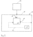
- FIG. 2 is another vacuum system shown.
- This also comprises a vacuum safety valve 11, a vacuum pump 13, a pressure source 13 ', a vacuum pump housing 15 and a vacuum chamber 17.
- the illustration shows an internal configuration of the vacuum safety valve 11, ie the valve 11 is located inside the pump housing 15 and the vacuum chamber 17 is over the vacuum pump housing 15 is connected to the inlet 21 of the valve 11.
- the pressure source 13 ' is connected via an internal pressure line 63 to the valve 11.
- the outlet 23 of the valve 11 communicates with the gas inlet of a pumping system (not shown) of the vacuum pump 13.
- a vacuum safety valve 11 is characterized inter alia by the fact that it is in both an external configuration according to Fig. 1 as well as in an internal configuration according to Fig. 2 can be used.
- valve 11 In the Fig. 3 and 4 the valve 11 is shown in cross-section, in Fig. 3 the valve 11 is closed and in Fig. 4 is open.
- the valve 11 comprises a cuboid housing 19.
- the connections to the vacuum chamber 17 and to the vacuum pump 13 are indicated.
- Inlet 21 and outlet 23 of the valve 11 are each realized by a bore in the housing 19.
- a for connection to the chamber 17 serving flange member 59 is screwed.
- the inlet 21 opens into a channel section 25, which merges into a duct section 27a, 27b leading to the outlet 23 at right angles to the channel section 25, comprising a narrower section 27a adjoining the channel section 25 and a further section 27b forming a housing opening.
- This outlet-side housing opening is closed by means of a closing element 51 into which a flange element 61 serving for connection to the pump 13 is screwed.
- the channel portion 25 and the channel portion 27a, 27b form a flow path from the inlet 21 to the outlet 23.
- a valve portion 29 In this flow path is a valve portion 29 with a closure element 31, which is positioned in the transition between the narrower portion 27a and the further portion 27b and designed as a valve plate is.
- the closure element 31 is located in the further section 27a and lies in the closed position shown here with its side facing away from the outlet 23 at a forming the transition shoulder 57 of the housing 19 with the interposition of an O-ring seal 49.
- O-ring seal 49 instead of the illustrated O-ring seal 49 different sealing elements can be used.
- the sealing element may for example also be designed as a flat gasket.
- the closure element 31 is mounted on an elongated actuator 37 and fixed by means of two retaining rings 45 in the longitudinal direction of the actuator 37.
- the actuator 37 extends from an outlet side arranged in the housing 19 bearing element 53 through the further portion 27 b, the closure member 31, the narrower portion 27 a and a housing wall 41 in a housing 19 formed in the control chamber 33.
- the housing wall 41 separates the control chamber 33 from the valve region 29.
- the rod-shaped shaft of the actuator 37 is on the one hand by the disc-shaped bearing element 53, which is supported on the outlet side in an end circumferential recess of the housing 19 and has a central passage for the shaft of the actuator 37, and on the other centered by the housing wall 41 and guided.
- a diaphragm 35 is arranged, which fluid-tightly separates a pressure side of a control side of the control chamber 33.
- the membrane 35 is fixed on the pressure side to the housing 19 and, for this purpose, is arranged with a bead region delimiting an inlet opening of the membrane 35 in a peripheral groove formed in the housing 19. A region of the membrane 35 which delimits the bead section radially inward is clamped between the housing front side and a closure element in the form of a cover 47.
- the actuator 37 At its end located in the control chamber 33, the actuator 37 has a hat-shaped head part 43. Within the head part 43 and on the actuator 37 serving as a return member helical compression spring 39 is arranged. The helical compression spring 39 is partially surrounded by the head part 43 in the closed position shown here and extends between the bottom of the head part 43 and the housing wall 41.
- the membrane 35 rests on the convex outer surface of the head part 43.
- the pressure-side part of the control chamber 33 is bounded by the diaphragm 35, the housing 19 and the cover 47.
- a pressure connection element 55 is screwed, which can be connected to a pressure line to connect the pressure side of the control chamber 33, for example, with a pressure source of a vacuum pump can (see. Fig. 1 ).
- Fig. 4 the vacuum safety valve 11 is shown in the open position, in which the membrane 35, for example by pressurizing hydraulic fluid flowing in via the pressure connection element 55, experiences a pressurization and has deformed.
- the actuator 37 is acted upon at its head part 43 and in the direction of the valve area 29 - in the Fig. 3 and 4 So to the right - moves until the head part 43 abuts against the housing wall 41.
- the helical compression spring 39 is compressed.
- the show Fig. 3 and 4 the valve 11 in a configuration with the covers 47, 51 and the flange elements 59, 61, which is designed for external use outside the vacuum pump (see, eg Fig. 1 ).
- the covers 47, 51 and the flange members 59, 61 are not required because the valve 11 can be integrated into the structure of the vacuum pump.
- the housing 19 and the functional components such as in particular the membrane 35, the actuator 37 together with spring 39 and valve plate 31 with retaining rings 45 and sealing element 49 and the bearing element 53 can be maintained unchanged for internal use or is a different structure, but functional to use the same valve. It is also possible to completely or partially dispense with a separate valve housing and to integrate the functional parts at least partially into the pump housing.
- a particularly advantageous application possibility for the safety valve according to the invention is to connect the pressure side of the control chamber 33 to an already existing pressure source of a vacuum pump, for example to a hydraulic pump of a rotary vane vacuum pump.
- a normally running running vacuum pump due to the then also working hydraulic pump thus even for a sufficiently high pressure to act on the valve diaphragm 35 and thus for keeping open the valve 11.
- This pressure drops when the vacuum pump intentionally or unintentionally fails, so that in this unsafe condition, the valve 11 closes automatically.
- the valve 11 only opens again when the pressure on the pressure side of the diaphragm 35 is sufficiently high. This is synonymous with a working hydraulic pump and thus a properly working vacuum pump, ie with a safe condition.
- valve 11 opens because a condition is met which does not necessarily mean a safe condition.
- the behavior of the valve 11 according to the invention is independent of the pressure difference between the vacuum chamber (recipient) and the vacuum pump.
- valve 11 Another advantage of the valve 11 according to the invention is that when the vacuum pump flooded and thus closed valve 11, the valve plate 31 not only by the spring 39, but in addition by the pressure difference between the at least partially evacuated vacuum chamber in communication valve inlet 21 and on Atmospheric pressure located valve outlet 23 pressed against its valve seat and so the contact pressure on the sealing member 49 of the valve disc 31 is still increased.
Abstract
Die vorliegende Erfindung betrifft ein Vakuumsicherheitsventil für eine Vakuumpumpe, insbesondere eine Drehschiebervakuumpumpe, mit einem Gehäuse mit einem zwischen einem Einlass und einem Auslass verlaufenden Strömungsweg für ein zu förderndes Gas, einem im Strömungsweg gelegenen Ventilbereich, in dem ein zwischen einer Geschlossenstellung und einer Offenstellung bewegbares Verschlusselement angeordnet ist, einem dem Ventilbereich zugeordneten Steuerraum, in dem eine eine Druckseite von einer Stellseite trennende Membran angeordnet ist, und einem zwischen der Membran und dem Verschlusselement wirksamen Stellglied, wobei das Verschlusselement mittels der druckseitig beaufschlagten Membran über das Stellglied gegen eine Rückstellkraft aus der Geschlossenstellung in die Offenstellung bewegbar und bei Wegfall der Membranbeaufschlagung aufgrund der Rückstellkraft zurück in die Geschlossenstellung bewegbar und in der Geschlossenstellung gehalten ist.The present invention relates to a vacuum safety valve for a vacuum pump, in particular a rotary vane vacuum pump, comprising a housing having a flow path for a gas to be conveyed between an inlet and an outlet, a valve region located in the flow path, in which a closing element movable between a closed position and an open position is arranged, a valve region associated with the control chamber, in which a pressure side of a control side separating membrane is arranged, and an effective between the membrane and the closure member actuator, wherein the closure element by means of the pressure side acted upon membrane via the actuator against a restoring force from the closed position can be moved into the open position and moved back to the closed position and held in the closed position in case of elimination of membrane loading due to the restoring force.
Description
Die vorliegende Erfindung betrifft ein Vakuumsicherheitsventil für eine Vakuumpumpe, insbesondere eine Drehschiebervakuumpumpe, und ferner ein das Vakuumsicherheitsventil, eine Vakuumpumpe und eine Vakuumkammer umfassendes Vakuumsystem.The present invention relates to a vacuum safety valve for a vacuum pump, more particularly to a rotary vane vacuum pump, and further to a vacuum system including the vacuum safety valve, a vacuum pump and a vacuum chamber.
Drehschiebervakuumpumpen beispielsweise sind ölüberlagerte Rotationsverdrängerpumpen und werden zunehmend mit einem Vakuumsicherheitsventil ausgestattet. Vakuumsicherheitsventile trennen die Pumpe vom Rezipienten, sobald es zu einem gewollten oder ungewollten Stillstand der Pumpe oder einer anderen Störung kommt. Hierdurch wird das Druckniveau im Rezipienten gehalten und insbesondere das Eindringen von Öl oder anderen Verunreinigungen in den Rezipienten verhindert.Rotary vane vacuum pumps, for example, are oil-superposed rotary positive displacement pumps and are increasingly being equipped with a vacuum safety valve. Vacuum safety valves separate the pump from the recipient as soon as there is a wanted or unwanted shutdown of the pump or another fault. As a result, the pressure level is maintained in the recipient and in particular prevents the ingress of oil or other contaminants in the recipient.
Die bisher eingesetzten Vakuumsicherheitsventile öffnen bei Unterschreiten einer bestimmten Druckdifferenz - zwischen dem Druck im Rezipienten und dem Druck in der Pumpe - selbsttätig. Das Öffnen des Vakuumsicherheitsventils im Anschluss an ein störungsbedingtes Schließen ist damit allein von der Druckdifferenz abhängig. Es ist jedoch erstrebenswert, dass vor einem erneuten Öffnen des Vakuumsicherheitsventils ein sicherer Zustand erreicht wird, in welchem das Problem, welches zur Schließung des Vakuumsicherheitsventils führte, behoben wurde. Wird die Druckdifferenz beispielsweise vor dem Herstellen dieses sicheren Zustandes erreicht, so wird ein herkömmliches Vakuumsicherheitsventil zwangsläufig öffnen, obwohl eben dieser sichere Zustand noch nicht wieder erreicht wurde. Ein vorzeitiges Öffnen des Ventils und somit eine Wiederherstellung der strömungstechnischen Verbindung zwischen Pumpe und Rezipienten in einem nicht sicheren Zustand kann schwerwiegende Folgen haben.The previously used vacuum safety valves open when falling below a certain pressure difference - between the pressure in the recipient and the pressure in the pump - automatically. The opening of the vacuum safety valve following a fault-related closing is thus dependent solely on the pressure difference. However, it is desirable that before reopening the vacuum safety valve, a safe state is achieved in which the problem leading to the closure of the vacuum safety valve has been resolved. If the pressure difference is reached, for example, before this safe state is established, then a conventional vacuum safety valve will inevitably open, although precisely this safe state has not yet been reached again. A premature opening of the valve and thus a restoration of the fluidic Connection between the pump and the recipient in a non-safe condition can have serious consequences.
Der Erfindung liegt somit die Aufgabe zugrunde, ein Vakuumsicherheitsventil bereitzustellen, welches eine erhöhte Sicherheit bietet.The invention is therefore based on the object to provide a vacuum safety valve, which provides increased safety.
Diese Aufgabe wird durch ein Vakuumsicherheitsventil mit den Merkmalen des Anspruchs 1 und ein Vakuumsystem nach Anspruch 13 gelöst.This object is achieved by a vacuum safety valve with the features of claim 1 and a vacuum system according to
Das erfindungsgemäße Vakuumsicherheitsventil umfasst ein Gehäuse mit einem zwischen einem Einlass und einem Auslass verlaufenden Strömungsweg für ein zu förderndes Gas, einen in dem Strömungsweg gelegenen Ventilbereich, in dem ein zwischen einer Offenstellung und einer Geschlossenstellung bewegbares Verschlusselement angeordnet ist, einen dem Ventilbereich zugeordneten Steuerraum, in dem eine eine Druckseite von einer Stellseite trennende Membran angeordnet ist, und ein zwischen der Membran und dem Verschlusselement wirksamen Stellglied, wobei das Verschlusselement mittels der druckseitig beaufschlagten Membran über das Stellglied gegen eine Rückstellkraft aus der Geschlossenstellung in die Offenstellung bewegbar und bei Wegfall der Membranbeaufschlagung aufgrund der Rückstellkraft zurück in die Geschlossenstellung bewegbar und in der Geschlossenstellung gehalten ist.The vacuum safety valve according to the invention comprises a housing with a flow path extending between an inlet and an outlet for a gas to be conveyed, a valve region located in the flow path, in which a closing element movable between an open position and a closed position is arranged, a control chamber associated with the valve region a diaphragm separating a pressure side from an actuating side, and an actuator acting between the diaphragm and the closure element, the closure element being movable from the closed position to the open position by means of the diaphragm loaded via the actuator against the restoring force and if the membrane is not loaded by the diaphragm the restoring force is moved back into the closed position and held in the closed position.
Bei dem erfindungsgemäßen Vakuumsicherheitsventil - im Folgenden auch einfach als Ventil bezeichnet - muss zur Bewegung des Stellgliedes aus der sicheren Geschlossenstellung in die Offenstellung eine Rückstellkraft überwunden werden. Dies kann nur durch eine Druckbeaufschlagung der Membran erreicht werden.In the vacuum safety valve according to the invention - hereinafter also referred to simply as a valve - a restoring force must be overcome to move the actuator from the safe closed position into the open position. This can only be achieved by pressurizing the membrane.
Das erfindungsgemäße Ventil öffnet daher nicht - wie herkömmliche Vakuumsicherheitsventile - zwangsläufig ab dem Unterschreiten einer bestimmten Druckdifferenz zwischen Rezipient und Pumpe. Vielmehr ermöglicht es die Erfindung beispielsweise, Bedingungen oder Zustände zu definieren, die als sicher gelten und eine manuelle oder automatische Druckbeaufschlagung der Membran erlauben oder bewirken. Insbesondere kann ein Wiederanlaufen der Pumpe als ein sicherer Zustand definiert und die Pumpe selbst für die Druckbeaufschlagung benutzt werden.The valve according to the invention therefore does not open - as conventional vacuum safety valves - inevitably from falling below a certain pressure difference between the recipient and the pump. Rather, the invention makes it possible, for example, Define conditions or conditions that are considered safe and allow or effect manual or automatic pressurization of the membrane. In particular, a restart of the pump can be defined as a safe state and the pump itself can be used for the pressurization.
Das erfindungsgemäße Vakuumsicherheitsventil sorgt folglich für eine erhöhte Sicherheit, da ein ungewolltes Öffnen des Ventils nach einem störungsbedingten Schließen verhindert werden kann.The vacuum safety valve according to the invention consequently provides for increased safety, since unintentional opening of the valve can be prevented after a fault-related closing.
Unter dem Begriff "Gas" sind auch solche Medien zu verstehen, die nicht ausschließlich gasförmig sind, sondern auch Flüssigkeitsanteile wie insbesondere kleine Tröpfchen enthalten. Ein Anteile von Wasserdampf enthaltendes Medium beispielsweise ist auch ein Gas im Sinne der vorliegenden Offenbarung.The term "gas" is also to be understood as meaning those media which are not exclusively gaseous, but also contain liquid fractions, in particular small droplets. A portion of water vapor-containing medium, for example, is also a gas within the meaning of the present disclosure.
Vorteilhafte Ausführungsformen der Erfindung sind auch in den Ansprüchen, der nachfolgenden Beschreibung sowie den Figuren angegeben.Advantageous embodiments of the invention are also set forth in the claims, the following description and the figures.
Gemäß einer Ausführungsform ist druckseitig der Druck im Steuerraum in der Offenstellung höher als in der Geschlossenstellung. Das Ventil kann folglich durch Erhöhen des Drucks geöffnet werden, Insbesondere ist es dadurch nicht erforderlich, zum Öffnen des Ventils den Steuerraum mit einem Unterdruck zu beaufschlagen.According to one embodiment, the pressure in the control chamber in the open position is higher on the pressure side than in the closed position. The valve can thus be opened by increasing the pressure. In particular, it is therefore not necessary to apply a negative pressure to open the valve to the control chamber.
Alternativ oder zusätzlich kann in der Geschlossenstellung die Membran weiter von dem Ventilbereich entfernt gelegen sein als in der Offenstellung.Alternatively or additionally, in the closed position, the membrane may be situated farther away from the valve region than in the open position.
Gemäß einer weiteren Ausführungsform ist der Steuerraum in dem Gehäuse ausgebildet und räumlich, insbesondere fluiddicht, von dem Ventilbereich getrennt, insbesondere durch wenigstens eine Gehäusewand.According to a further embodiment, the control chamber is formed in the housing and spatially, in particular fluid-tight, separated from the valve region, in particular by at least one housing wall.
Die Anordnung des Steuerraumes im Gehäuse ermöglicht eine platzsparende Bauweise des Ventils. Durch die räumliche Trennung des Steuerraumes von dem Ventilbereich kann eine zuverlässige Druckbeaufschlagung der Membran realisiert werden, ohne dass sich die Druckzustände des Steuerraumes und des Ventilbereichs gegenseitig beeinflussen.The arrangement of the control chamber in the housing allows a space-saving design of the valve. The spatial separation of the control chamber from the valve region, a reliable pressurization of the membrane can be realized without the pressure states of the control chamber and the valve area influence each other.
Bei einer Weiterbildung weist das Stellglied eine langgestreckte Form auf und erstreckt sich geradlinig zwischen dem Steuerraum und dem Ventilbereich.In a further development, the actuator has an elongated shape and extends in a straight line between the control chamber and the valve region.
Gemäß einer weiteren Ausführungsform weist das Stellglied im Bereich eines Endes ein mit der Membran unmittelbar zusammenwirkendes Kopfteil auf und ist im Bereich eines anderen Endes mit dem Verschlusselement verbunden. Das Stellglied kann einstückig mit dem Verschlusselement ausgebildet sein. Alternativ kann ein separates Verschlusselement vorgesehen sein, das durch geeignete Mittel an dem Stellglied befestigt ist.According to a further embodiment, the actuator has in the region of one end a directly cooperating with the membrane head part and is connected in the region of another end with the closure element. The actuator may be formed integrally with the closure element. Alternatively, a separate closure element may be provided which is secured by suitable means to the actuator.
Gemäß einer weiteren Ausführungsform ist das Kopfteil ballig ausgeführt und die Membran umgreift das Kopfteil zumindest teilweise. Durch die ballige Ausführung kann der Membran eine relativ große Angriffsfläche geboten werden. Bei der Membran handelt es sich insbesondere um eine Rollmembran, es können jedoch auch andere Membranbauarten eingesetzt werden.According to a further embodiment, the head part is crowned and the membrane surrounds the head part at least partially. Due to the spherical design of the membrane can be offered a relatively large attack surface. In particular, the membrane is a rolling membrane, but other types of membranes may be used.
Gemäß einer Weiterbildung ist das Kopfteil hutförmig ausgeführt und ein Rückstellglied teilweise in dem Kopfteil angeordnet. Hierdurch ist eine optimale Nutzung des Platzes innerhalb des Steuerraumes möglich und gleichzeitig eine relativ große Angriffsfläche für die Membran vorhanden, die zudem durch das Kopfteil von dem Rückstellglied getrennt ist.According to a further development, the head part is hat-shaped and a return member is partially arranged in the head part. As a result, an optimal use of the space within the control room is possible and at the same time a relatively large attack surface for the membrane is present, which is also separated by the head part of the return member.
Gemäß einer weiteren Ausführungsform umfasst ein Rückstellglied zumindest ein Federelement, insbesondere eine Schraubendruckfeder.According to a further embodiment, a return element comprises at least one spring element, in particular a helical compression spring.
Des Weiteren kann vorgesehen sein, dass ein Rückstellglied im Steuerraum zwischen einem Kopfteil des Stellgliedes und einer den Steuerraum begrenzenden Gehäusewand angeordnet ist, insbesondere einer den Steuerraum von dem Strömungsweg trennenden Gehäusewand. An der Gehäusewand kann sich das Rückstellglied folglich abstützen. Die Trennung des Steuerraums von dem Strömungsweg mittels der Gehäusewand kann hierbei gasdicht ausgeführt sein, was jedoch nicht zwingend erforderlich ist.Furthermore, it can be provided that a return member is arranged in the control chamber between a head part of the actuator and a housing wall delimiting the control chamber, in particular a housing wall separating the control chamber from the flow path. On the housing wall, the return member can therefore be supported. The separation of the control chamber from the flow path by means of the housing wall can be made gas-tight, but this is not absolutely necessary.
Bevorzugt liegt ein Kopfteil des Stellgliedes in der Offenstellung an einer den Steuerraum begrenzenden Gehäusewand an, insbesondere an einer den Steuerraum von dem Strömungsweg trennenden Gehäusewand. Hierdurch kann die Gehäusewand als Endanschlag für das Kopfteil und somit das Stellglied dienen, wodurch der maximale Stellweg für das Verschlusselement und somit die Offenstellung des Ventils genau definiert werden kann.Preferably, a head part of the actuator is in the open position on a housing wall delimiting the control chamber, in particular on a housing wall separating the control chamber from the flow path. In this way, the housing wall serve as an end stop for the head part and thus the actuator, whereby the maximum travel for the closure element and thus the open position of the valve can be precisely defined.
Gemäß einer weiteren Ausführungsform ist der Strömungsweg von einem sich zwischen dem Einlass und dem Auslass erstreckenden Strömungskanal gebildet, wobei der Einlass und der Auslass nicht auf einer durch den Strömungskanal verlaufenden Geraden liegen und/oder der Strömungsweg wenigstens zwei Kanalabschnitte mit nicht zusammenfallenden Längsachsen aufweist. Ein solcher Strömungsweg ermöglicht eine in konstruktiver Hinsicht einfache Übertragung der Membranbewegung auf das Verschlusselement mittels des Stellgliedes. Insbesondere ist es hierdurch möglich, ein vergleichsweise einfach aufgebautes, z.B. in Form einer geraden Stange vorgesehenes Stellglied zu verwenden. Bevorzugt erstreckt sich das von dem Steuerraum ausgehende Stellglied durch einen Teil des Strömungskanals hindurch, insbesondere an dem einen Kanalabschnitt vorbei zu dem in dem anderen Kanalabschnitt gelegenen Ventilbereich.According to a further embodiment, the flow path is formed by a flow channel extending between the inlet and the outlet, wherein the inlet and the outlet do not lie on a straight line through the flow channel and / or the flow path has at least two channel sections with non-coincident longitudinal axes. Such a flow path allows a structurally simple transfer of membrane movement to the closure element by means of the actuator. In particular, it is thereby possible to use a comparatively simple design, for example, provided in the form of a straight rod actuator. The actuator extending from the control chamber preferably extends through a part of the flow channel, in particular past the one channel section to the valve region located in the other channel section.
Gemäß einer weiteren Ausführungsform sind die Kanalabschnitte jeweils in Form einer im Gehäuse ausgebildeten Bohrung vorgesehen, wobei bevorzugt die Bohrungen jeweils von einer Außenseite des Gehäuses ausgehen und die eine Bohrung den Einlass und die andere Bohrung den Auslass bildet.According to a further embodiment, the channel sections are each provided in the form of a bore formed in the housing, wherein preferably the bores each originate from an outer side of the housing and the one bore forms the inlet and the other bore forms the outlet.
Des Weiteren kann vorgesehen sein, dass der Ventilbereich an einem Übergang zwischen zwei Abschnitten des Strömungsweges mit unterschiedlich großem Strömungsquerschnitt gelegen ist, wobei sich das Stellglied durch zumindest einen Teil des engeren Abschnitts hindurch zu dem Verschlusselement erstreckt und das Verschlusselement in dem weiteren Abschnitt angeordnet ist und in der Geschlossenstellung die Mündung des engeren Abschnitts in den weiteren Abschnitt verschließt.Furthermore, it can be provided that the valve region is located at a transition between two sections of the flow path with different sized flow cross-section, wherein the actuator extends through at least a portion of the narrower section to the closure element and the closure element is disposed in the further section and closed in the closed position, the mouth of the narrower section in the further section.
Ein solcher Übergang zwischen Kanalabschnitten mit unterschiedlichen Querschnittsgrößen kann durch ein eine vergleichsweise einfache Form aufweisendes Verschlusselement zuverlässig abgedichtet werden, z.B. durch ein Verschlusselement in Form einer zylindrischen Scheibe.Such a transition between channel sections having different cross-sectional sizes can be reliably sealed by a closure element having a comparatively simple shape, e.g. by a closure element in the form of a cylindrical disc.
Bei dem erfindungsgemäßen Vakuumsystem, das zumindest eine Vakuumpumpe, wenigstens eine Vakuumkammer und zumindest ein erfindungsgemäßes Vakuumsicherheitsventil umfasst, ist der Ventileinlass der Vakuumkammer und der Ventilauslass der Vakuumpumpe zugeordnet.In the vacuum system according to the invention, which comprises at least one vacuum pump, at least one vacuum chamber and at least one vacuum safety valve according to the invention, the valve inlet is assigned to the vacuum chamber and the valve outlet is assigned to the vacuum pump.
Gemäß einer Ausführungsform ist die Druckseite des Steuerraumes an eine Druckquelle, insbesondere an eine Hydraulikdruckquelle, der Vakuumpumpe angeschlossen, insbesondere unter Umgehung der Membran und/oder des Stellgliedes, wobei die Druckquelle derart betreibbar ist, dass bei bestimmungsgemäßem Pumpbetrieb der Vakuumpumpe die Membran beaufschlagt ist und die Offenstellung des Ventils aufrechterhalten bleibt und im Fall einer Störung des Pumpbetriebs oder nach dem Ausschalten der Vakuumpumpe die Membranbeaufschlagung wegfällt.According to one embodiment, the pressure side of the control chamber is connected to a pressure source, in particular to a hydraulic pressure source, the vacuum pump, in particular bypassing the membrane and / or the actuator, wherein the pressure source is operable such that when intended pumping the vacuum pump, the membrane is acted upon and the open position of the valve is maintained and in the event of a failure of the pumping operation or after switching off the vacuum pump, the diaphragm loading is eliminated.
Hierbei kann in vorteilhafter Weise eine ohnehin vorhandene Druckquelle der Vakuumpumpe zur Druckbeaufschlagung der Membran genutzt werden. Insbesondere dann, wenn im Anschluss an eine ordnungsgemäße oder störungsbedingte Unterbrechung des Pumpbetriebs ein Wiederanlaufen der Vakuumpumpe als ein sicherer Zustand gilt, öffnet sich das Ventil automatisch, da mit dem Wiederanlaufen der Pumpe auch die Druckquelle, beispielsweise eine integrierte Hydraulikpumpe der Vakuumpumpe, wieder in Betrieb geht und so die Membran erneut beaufschlagt wird.In this case, an already existing pressure source of the vacuum pump for pressurizing the membrane can be used in an advantageous manner. In particular, if a restart of the vacuum pump is considered to be a safe state following a proper or malfunctioning interruption of the pumping operation, the valve opens automatically, as with the restart of the pump and the pressure source, such as an integrated hydraulic pump of the vacuum pump, back into operation goes and so the membrane is applied again.
Gemäß einer möglichen Ausgestaltung des Systems ist eine externe Konfiguration mit außerhalb der Vakuumpumpe angeordnetem Vakuumsicherheitsventil vorgesehen.According to one possible embodiment of the system, an external configuration is provided with a vacuum safety valve arranged outside the vacuum pump.
Alternativ ist eine interne Konfiguration vorgesehen, bei der das Vakuumsicherheitsventil oder ein Gehäuse des Vakuumsicherheitsventils innerhalb eines Vakuumpumpengehäuses der Vakuumpumpe angeordnet ist oder einen Teil des Vakuumpumpengehäuses bildet oder zumindest teilweise von dem Vakuumpumpengehäuse gebildet ist.Alternatively, an internal configuration is provided in which the vacuum safety valve or a housing of the vacuum safety valve is disposed within a vacuum pump housing of the vacuum pump or forms part of the vacuum pump housing or at least partially formed by the vacuum pump housing.
Das Gehäuse des Vakuumsicherheitsventils kann derart ausgestaltet sein, dass das Ventil sowohl in einer externen als auch in einer internen Konfiguration verwendbar ist. Bevorzugt ist vorgesehen, dass in der externen oder internen Konfiguration zumindest eine dem Steuerraum oder dem Strömungsweg zugeordnete Gehäuseöffnung von einem in der internen bzw. externen Konfiguration entfernten, mit dem Gehäuse lösbar verbundenen Abschlusselement gebildet ist.The housing of the vacuum safety valve may be configured such that the valve is usable in both an external and an internal configuration. It is preferably provided that, in the external or internal configuration, at least one housing opening assigned to the control chamber or the flow path is formed by a terminating element which is remote from the internal or external configuration and is detachably connected to the housing.
Durch die beiden möglichen Konfigurationen ist ein flexibler, universeller Einsatz des Vakuumsicherheitsventils in verschiedenen Vakuumsystemen möglich.The two possible configurations allow a flexible, universal use of the vacuum safety valve in various vacuum systems.
Durch das Abschlusselement kann das Gehäuse an die jeweils gewünschte Konfiguration angepasst werden. Insbesondere kann das Abschlusselement als Adapter ausgebildet sein, der es ermöglich, das Gehäuse an die jeweils vorhandene Anschlusssituation anzupassen. Beispielsweise kann in einer externen Konfiguration das Abschlusselement den Anschluss der Druckseite des Steuerraumes an einen Druckanschluss der Vakuumpumpe ermöglichen, der bei einer internen Konfiguration nicht möglich oder nicht erforderlich ist, wenn die Gehäuseöffnung des Ventils direkt an die Druckquelle der Vakuumpumpe angeschlossen werden kann. Des Weiteren kann das Abschlusselement zur Aufnahme eines insbesondere ein- und ausschraubbaren Flanschelementes dienen, über welches in der externen Konfiguration die Vakuumpumpe an eine den Auslass des Ventils bildende Gehäuseöffnung angeschlossen werden kann.By the end element, the housing can be adapted to the particular desired configuration. In particular, the end element can be designed as an adapter, which makes it possible to adapt the housing to the respective existing connection situation. For example, in an external configuration, the termination member may allow the connection of the pressure side of the control chamber to a pressure port of the vacuum pump, which is not possible or necessary in an internal configuration if the valve opening of the valve can be directly connected to the pressure source of the vacuum pump. Furthermore, the closing element can serve for receiving a flange element that can be screwed in and out, in particular, via which, in the external configuration, the vacuum pump can be connected to a housing opening forming the outlet of the valve.
Die Erfindung wird nachfolgend lediglich beispielhaft unter Bezugnahme auf die Zeichnung erläutert.
- Fig. 1
- zeigt ein erfindungsgemäßes Vakuumsystem mit einer Vakuumpumpe, einer Vakuumkammer und einem erfindungsgemäßen Vakuumsicherheitsventil in externer Konfiguration.
- Fig. 2
- zeigt ein erfindungsgemäßes Vakuumsystem mit einer Vakuumpumpe, einer Vakuumkammer und einem erfindungsgemäßen Vakuumsicherheitsventil in interner Konfiguration.
- Fig. 3
- zeigt ein Ausführungsbeispiel eines erfindungsgemäßen Vakuumsicherheitsventils in der Geschlossenstellung.
- Fig. 4
- zeigt das Vakuumsicherheitsventil von
Fig. 3 in der Offenstellung.
- Fig. 1
- shows a vacuum system according to the invention with a vacuum pump, a vacuum chamber and a vacuum safety valve according to the invention in an external configuration.
- Fig. 2
- shows a vacuum system according to the invention with a vacuum pump, a vacuum chamber and a vacuum safety valve according to the invention in an internal configuration.
- Fig. 3
- shows an embodiment of a vacuum safety valve according to the invention in the closed position.
- Fig. 4
- shows the vacuum safety valve of
Fig. 3 in the open position.
In
In
Das nachstehend anhand der
In den
Das Ventil 11 umfasst ein quaderförmiges Gehäuse 19. Die Verbindungen zur Vakuumkammer 17 und zur Vakuumpumpe 13 sind angedeutet. Einlass 21 und Auslass 23 des Ventils 11 sind jeweils durch eine Bohrung im Gehäuse 19 realisiert. In die einlassseitige Bohrung ist ein zum Anschluss an die Kammer 17 dienendes Flanschelement 59 eingeschraubt.The
Der Einlass 21 mündet in einen Kanalabschnitt 25, der in einen zum Auslass 23 führenden, rechtwinklig zum Kanalabschnitt 25 verlaufenden Kanalabschnitt 27a, 27b übergeht, der einen sich an den Kanalabschnitt 25 anschließenden engeren Abschnitt 27a und einen eine Gehäuseöffnung bildenden weiteren Abschnitt 27b umfasst. Diese auslassseitige Gehäuseöffnung ist mittels eines Abschlusselements 51 verschlossen, in die ein zum Anschluss an die Pumpe 13 dienendes Flanschelement 61 eingeschraubt ist.The
Der Kanalabschnitt 25 und der Kanalabschnitt 27a, 27b bilden einen Strömungsweg vom Einlass 21 zum Auslass 23. In diesem Strömungsweg befindet sich ein Ventilbereich 29 mit einem Verschlusselement 31, welches im Übergang zwischen dem engeren Abschnitt 27a und dem weiteren Abschnitt 27b positioniert und als Ventilteller ausgeführt ist. Das Verschlusselement 31 befindet sich dabei im weiteren Abschnitt 27a und liegt in der hier dargestellten Geschlossenstellung mit seiner dem Auslass 23 abgewandten Seite an einer den Übergang bildenden Schulter 57 des Gehäuses 19 unter Zwischenlage einer O-Ring-Dichtung 49 an. An Stelle der gezeigten O-Ring-Dichtung 49 können verschiedene Dichtungselemente eingesetzt werden. Das Dichtungselement kann beispielsweise auch als Flachdichtung ausgeführt sein.The
Das Verschlusselement 31 ist auf einem langgestreckten Stellglied 37 befestigt und mittels zweier Sicherungsringe 45 in Längsrichtung des Stellgliedes 37 fixiert. Das Stellglied 37 erstreckt sich von einem auslassseitig im Gehäuse 19 angeordneten Lagerelement 53 durch den weiteren Abschnitt 27b, das Verschlusselement 31, den engeren Abschnitt 27a und eine Gehäusewand 41 in einen im Gehäuse 19 ausgebildeten Steuerraum 33 hinein. Die Gehäusewand 41 trennt den Steuerraum 33 von dem Ventilbereich 29.The
Der stangenförmige Schaft des Stellgliedes 37 ist zum einen durch das scheibenförmige Lagerelement 53, das auslassseitig in einer stirnseitigen Umfangsausnehmung des Gehäuses 19 abgestützt ist und eine zentrale Durchführung für den Schaft des Stellgliedes 37 aufweist, und zum anderen durch die Gehäusewand 41 zentrierend gehalten und geführt.The rod-shaped shaft of the
In dem Steuerraum 33 ist eine Membran 35 angeordnet, welche eine Druckseite von einer Stellseite des Steuerraumes 33 fluiddicht trennt. Die Membran 35 ist druckseitig am Gehäuse 19 fixiert und hierzu mit einem eine Einlassöffnung der Membran 35 begrenzenden Wulstbereich in einer stirnseitig im Gehäuse 19 ausgebildeten Umfangsnut angeordnet. Ein den Wulstabschnitt radial innen begrenzender Bereich der Membran 35 ist zwischen der Gehäusestirnseite und einem Abschlusselement in Form eines Deckels 47 eingeklemmt.In the
An seinem im Steuerraum 33 befindlichen Ende weist das Stellglied 37 ein hutförmiges Kopfteil 43 auf. Innerhalb des Kopfteils 43 und auf dem Stellglied 37 ist eine als Rückstellglied dienende Schraubendruckfeder 39 angeordnet. Die Schraubendruckfeder 39 ist in der hier dargestellten Geschlossenstellung teilweise von dem Kopfteil 43 umgeben und erstreckt sich zwischen dem Boden des Kopfteils 43 und der Gehäusewand 41.At its end located in the
Die Membran 35 liegt stellseitig an der balligen Außenfläche des Kopfteils 43 an. Der druckseitige Teil des Steuerraumes 33 wird durch die Membran 35, das Gehäuse 19 und den Deckel 47 begrenzt. In eine Öffnung des Deckels 47 ist ein Druckanschlusselement 55 geschraubt, das an eine Druckleitung angeschlossen werden kann, um die Druckseite des Steuerraumes 33 z.B. mit einer Druckquelle einer Vakuumpumpe verbinden zu können (vgl.
In
Durch diese gegen die Rückstellkraft der Feder 39 erfolgende Stellbewegung hebt das im Ventilbereich 29 am Stellglied 37 angebrachte Verschlusselement 31 von seinem von der Schulter 57 des Gehäuses 19 gebildeten Ventilsitz ab. Der Strömungsweg vom Einlass 21 zum Auslass 23 ist nicht mehr durch das Verschlusselement 31 unterbrochen. Das Ventil 11 ist geöffnet.By taking place against the restoring force of the
Wie bereits erwähnt, zeigen die
Wie im Einleitungsteil bereits erwähnt, besteht eine besonders vorteilhafte Einsatzmöglichkeit für das erfindungsgemäße Sicherheitsventil darin, die Druckseite des Steuerraumes 33 an eine ohnehin vorhandene Druckquelle einer Vakuumpumpe anzuschließen, z.B. an eine Hydraulikpumpe einer Drehschiebervakuumpumpe. Unabhängig davon, ob eine externe (z.B.
Erfindungsgemäß kann es folglich nicht zu Situationen kommen, in denen das Ventil 11 öffnet, weil eine Bedingung erfüllt ist, die nicht zwangsläufig einen sicheren Zustand bedeutet. Insbesondere ist das Verhalten des erfindungsgemäßen Ventils 11 unabhängig von der Druckdifferenz zwischen Vakuumkammer (Rezipient) und Vakuumpumpe.Consequently, according to the invention, there can not be situations in which the
Ein weiterer Vorteil des erfindungsgemäßen Ventils 11 besteht darin, dass bei gefluteter Vakuumpumpe und somit geschlossenem Ventil 11 der Ventilteller 31 nicht nur durch die Feder 39, sondern zusätzlich durch die Druckdifferenz zwischen dem mit der zumindest teilweise evakuierten Vakuumkammer in Verbindung stehenden Ventileinlass 21 und dem auf Atmosphärendruck befindlichen Ventilauslass 23 gegen seinen Ventilsitz gedrückt und so der Anpressdruck auf das Dichtungselement 49 des Ventiltellers 31 noch erhöht wird.Another advantage of the
- 1111
- VakuumsicherheitsventilVacuum safety valve
- 1313
- Vakuumpumpevacuum pump
- 13'13 '
- Druckquellepressure source
- 1515
- Vakuumpumpengehäusevacuum pump housing
- 1717
- Vakuumkammervacuum chamber
- 1919
- Gehäusecasing
- 2121
- Einlassinlet
- 2323
- Auslassoutlet
- 2525
- Kanalabschnittchannel section
- 27a27a
- engerer Abschnittnarrower section
- 27b27b
- weiterer Abschnittanother section
- 2929
- Ventilbereichvalve area
- 3131
- Verschlusselement, VentiltellerClosing element, valve disc
- 3333
- Steuerraumcontrol room
- 3535
- Membranmembrane
- 3737
- Stellgliedactuator
- 3939
- Rückstellglied, Federelement, SchraubendruckfederReturn member, spring element, helical compression spring
- 4141
- Gehäusewandhousing wall
- 4343
- Kopfteilheadboard
- 4545
- Sicherungsringcirclip
- 4747
- Abschlusselementtermination element
- 4949
- Dichtungselementsealing element
- 5151
- Abschlusselementtermination element
- 5353
- Lagerelementbearing element
- 5555
- DruckanschlusselementPressure connection element
- 5757
- Schultershoulder
- 5959
- Flanschelementflange
- 6161
- Flanschelementflange
- 6363
- Druckleitungpressure line
Claims (15)
eine Drehschiebervakuumpumpe, mit
einem Gehäuse (19) mit einem zwischen einem Einlass (21) und einem Auslass (23) verlaufenden Strömungsweg (25, 27a, 27b) für ein zu förderndes Gas,
einem im Strömungsweg (25, 27a, 27b) gelegenen Ventilbereich (29), in dem ein zwischen einer Geschlossenstellung und einer Offenstellung bewegbares Verschlusselement (31) angeordnet ist,
einem dem Ventilbereich (29) zugeordneten Steuerraum (33), in dem eine eine Druckseite von einer Stellseite trennende Membran (35) angeordnet ist, und
einem zwischen der Membran (35) und dem Verschlusselement (31) wirksamen Stellglied (37),
wobei das Verschlusselement (31) mittels der druckseitig beaufschlagten Membran (35) über das Stellglied (37) gegen eine Rückstellkraft aus der Geschlossenstellung in die Offenstellung bewegbar und bei Wegfall der Membranbeaufschlagung aufgrund der Rückstellkraft zurück in die Geschlossenstellung bewegbar und in der Geschlossenstellung gehalten ist.Vacuum safety valve (11) for a vacuum pump (13), in particular
a rotary vane vacuum pump, with
a housing (19) having a flow path (25, 27a, 27b) extending between an inlet (21) and an outlet (23) for a gas to be delivered,
a valve region (29) located in the flow path (25, 27a, 27b), in which a closure element (31), which is movable between a closed position and an open position, is arranged,
a valve chamber (29) associated control chamber (33) in which a pressure side of a control side separating membrane (35) is arranged, and
an actuator (37) acting between the diaphragm (35) and the closure element (31),
wherein the closure element (31) by means of the pressure side acted upon membrane (35) via the actuator (37) movable against a restoring force from the closed position to the open position and in case of elimination of Membranbeaufschlagung due to the restoring force back into the closed position and held in the closed position.
wobei druckseitig der Druck im Steuerraum (33) in der Offenstellung höher ist als in der Geschlossenstellung, und/oder wobei in der Geschlossenstellung die Membran (35) weiter von dem Ventilbereich (29) entfernt gelegen ist als in der Offenstellung.Vacuum safety valve (11) according to claim 1,
wherein the pressure in the control chamber (33) in the open position is higher than in the closed position, and / or wherein in the closed position, the membrane (35) is located further away from the valve region (29) than in the open position.
wobei der Steuerraum (33) in dem Gehäuse (19) ausgebildet und räumlich von dem Ventilbereich (29) getrennt ist, insbesondere durch wenigstens eine Gehäusewand (41).Vacuum safety valve (11) according to claim 1 or 2,
wherein the control chamber (33) formed in the housing (19) and spatially separated from the valve region (29), in particular by at least one housing wall (41).
wobei das Stellglied (37) eine langgestreckte Form aufweist und sich geradlinig zwischen dem Steuerraum (33) und dem Ventilbereich (29) erstreckt.Vacuum safety valve (11) according to one of the preceding claims,
wherein the actuator (37) has an elongate shape and extends in a straight line between the control chamber (33) and the valve region (29).
wobei das Stellglied (37) im Bereich eines Endes ein mit der Membran (35) unmittelbar zusammenwirkendes Kopfteil (43) aufweist und im Bereich eines anderen Endes mit dem Verschlusselement (31) verbunden ist, wobei insbesondere das Stellglied (37) einstückig mit dem Verschlusselement (31) ausgebildet ist.Vacuum safety valve (11) according to one of the preceding claims,
wherein the actuator (37) in the region of one end has a directly cooperating with the membrane (35) head portion (43) and is connected in the region of another end with the closure element (31), wherein in particular the actuator (37) integral with the closure element (31) is formed.
wobei das Kopfteil (43) ballig ausgeführt ist und die Membran (35) das Kopfteil (43) zumindest teilweise umgreift.Vacuum safety valve (11) according to claim 5,
wherein the head part (43) is crowned and the membrane (35) at least partially surrounds the head part (43).
wobei das Kopfteil (43) hutförmig ausgeführt ist und ein Rückstellglied (39) teilweise in dem Kopfteil (43) angeordnet ist.Vacuum safety valve (11) according to claim 5 or 6,
wherein the head part (43) is hat-shaped and a return member (39) is partially disposed in the head part (43).
wobei ein Rückstellglied zumindest ein Federelement (39) umfasst, insbesondere eine Schraubendruckfeder.Vacuum safety valve (11) according to one of the preceding claims,
wherein a return member comprises at least one spring element (39), in particular a helical compression spring.
wobei ein Rückstellglied (39) im Steuerraum (33) zwischen einem Kopfteil (43) des Stellgliedes (37) und einer den Steuerraum (33) begrenzenden Gehäusewand (41) angeordnet ist, insbesondere einer den Steuerraum (33) von dem Strömungsweg (25, 27a, 27b) trennenden Gehäusewand (41).Vacuum safety valve (11) according to one of the preceding claims,
wherein a return member (39) is arranged in the control chamber (33) between a head part (43) of the actuator (37) and a housing wall (41) delimiting the control chamber (33), in particular one of the control chamber (33) and the flow path (25, 27a, 27b) separating the housing wall (41).
wobei der Strömungsweg (25, 27a, 27b) von einem sich zwischen dem Einlass 21) und dem Auslass (23) erstreckenden Strömungskanal gebildet ist, wobei der Einlass (21) und der Auslass (23) nicht auf einer durch den Strömungskanal verlaufenden Geraden liegen und/oder wobei der Strömungskanal wenigstens zwei Kanalabschnitte (25, 27a, 27b) mit nicht zusammenfallenden Längsachsen aufweist,
wobei insbesondere sich das von dem Steuerraum (33) ausgehende Stellglied (37) durch einen Teil des Strömungskanals hindurch erstreckt, insbesondere an dem einen Kanalabschnitt (25) vorbei zu dem in dem anderen Kanalabschnitt (27a, 27b) gelegenen Ventilbereich (29).Vacuum safety valve (11) according to one of the preceding claims,
wherein the flow path (25, 27a, 27b) is formed by a flow channel extending between the inlet 21) and the outlet (23), the inlet (21) and the outlet (23) not lying on a straight line through the flow channel and / or wherein the flow channel has at least two channel sections (25, 27a, 27b) with non-coincident longitudinal axes,
in particular, the actuator (37) extending from the control chamber (33) extends through part of the flow channel, in particular past the one channel section (25) to the valve section (29) located in the other channel section (27a, 27b).
wobei die Kanalabschnitte (25, 27a, 27b) jeweils in Form einer im Gehäuse (19) ausgebildeten Bohrung vorgesehen sind, wobei bevorzugt die Bohrungen jeweils von einer Außenseite des Gehäuses (19) ausgehen und die eine Bohrung den Einlass (21) und die andere Bohrung den Auslass (23) bildet.Vacuum safety valve (11) according to claim 10,
wherein the channel sections (25, 27a, 27b) are each provided in the form of a bore formed in the housing (19), wherein preferably the bores each extend from an outer side of the housing (19) and one bore the inlet (21) and the other Bore forms the outlet (23).
wobei der Ventilbereich (29) an einem Übergang zwischen zwei Abschnitten (27a, 27b) des Strömungsweges mit unterschiedlich großem Strömungsquerschnitt gelegen ist, wobei sich das Stellglied (37) durch zumindest einen Teil des engeren Abschnitts (27a) hindurch zu dem Verschlusselement (31) erstreckt und das Verschlusselement (31) in dem weiteren Abschnitt (27b) angeordnet ist und in der Geschlossenstellung die Mündung des engeren Abschnitts (27a) in den weiteren Abschnitt (27b) verschließt.Vacuum safety valve (11) according to one of the preceding claims,
the valve region (29) being located at a transition between two sections (27a, 27b) of the flow path of different size flow cross section, the actuator (37) passing through at least part of the narrower section (27a) to the closure element (31). and the closure element (31) is arranged in the further section (27b) and, in the closed position, closes the mouth of the narrower section (27a) into the further section (27b).
wobei der Ventileinlass (21) der Vakuumkammer (17) und der Ventilauslass (23) der Vakuumpumpe (13) zugeordnet ist.Vacuum system comprising a vacuum pump (13), a vacuum chamber (17) and a vacuum safety valve (11) according to one of the preceding claims,
wherein the valve inlet (21) is associated with the vacuum chamber (17) and the valve outlet (23) is associated with the vacuum pump (13).
wobei die Druckseite des Steuerraumes (33) an eine Druckquelle (13'), insbesondere an eine Hydraulikdruckquelle, der Vakuumpumpe (13) angeschlossen ist, insbesondere unter Umgehung der Membran (35) und/oder des Stellgliedes (37), wobei die Druckquelle (13') derart betreibbar ist, dass bei bestimmungsgemäßem Pumpbetrieb der Vakuumpumpe (13) die Membran (35) beaufschlagt ist und die Offenstellung des Ventils aufrechterhalten bleibt und im Fall einer Störung des Pumpbetriebs oder nach dem Ausschalten der Vakuumpumpe (13) die Membranbeaufschlagung wegfällt.Vacuum system according to claim 13,
wherein the pressure side of the control chamber (33) to a pressure source (13 '), in particular to a hydraulic pressure source, the vacuum pump (13) is connected, in particular bypassing the membrane (35) and / or the actuator (37), wherein the pressure source ( 13 ') is operable such that upon normal pumping operation of the vacuum pump (13), the membrane (35) is acted upon and the open position of the valve is maintained and in the event of failure of the pumping operation or after switching off the vacuum pump (13), the Membranbeaufschlagung omitted.
wobei eine externe Konfiguration mit außerhalb der Vakuumpumpe (13) angeordnetem Vakuumsicherheitsventil (11) oder eine interne Konfiguration vorgesehen ist, bei der das Vakuumsicherheitsventil (11) oder ein Gehäuse (19) des Vakuumsicherheitsventils (11) innerhalb eines Vakuumpumpengehäuses (15) der Vakuumpumpe (13) angeordnet ist oder einen Teil des Vakuumpumpengehäuses (15) bildet oder zumindest teilweise von dem Vakuumpumpengehäuse (15) gebildet ist, und/oder
wobei das Gehäuse (19) des Vakuumsicherheitsventils (11) sowohl in einer externen als auch in einer internen Konfiguration verwendbar ist, wobei in der externen Konfiguration zumindest eine dem Steuerraum (33) oder dem Strömungsweg (25, 27a, 27b) zugeordnete Gehäuseöffnung von einem in der internen Konfiguration entfernten, mit dem Gehäuse (19) lösbar verbundenen Abschlusselement (47, 51) gebildet ist.Vacuum system according to claim 13 or 14,
wherein an external configuration is provided with a vacuum safety valve (11) disposed outside the vacuum pump (13) or an internal configuration in which the vacuum safety valve (11) or housing (19) of the vacuum safety valve (11) is mounted within a vacuum pump housing (15) of the vacuum pump (11). 13) is arranged or forms part of the vacuum pump housing (15) or at least partially formed by the vacuum pump housing (15), and / or
wherein the housing (19) of the vacuum safety valve (11) is usable both in an external and in an internal configuration, wherein in the external configuration at least one of the control chamber (33) or the flow path (25, 27 a, 27 b) associated housing opening of a remote in the internal configuration, with the housing (19) releasably connected end member (47, 51) is formed.
Priority Applications (3)
| Application Number | Priority Date | Filing Date | Title |
|---|---|---|---|
| EP18169982.8A EP3561350B1 (en) | 2018-04-27 | 2018-04-27 | Vacuum relief valve |
| US16/390,124 US11280427B2 (en) | 2018-04-27 | 2019-04-22 | Vacuum safety valve |
| CN201910350323.6A CN110410320A (en) | 2018-04-27 | 2019-04-28 | Antivoid valve |
Applications Claiming Priority (1)
| Application Number | Priority Date | Filing Date | Title |
|---|---|---|---|
| EP18169982.8A EP3561350B1 (en) | 2018-04-27 | 2018-04-27 | Vacuum relief valve |
Publications (2)
| Publication Number | Publication Date |
|---|---|
| EP3561350A1 true EP3561350A1 (en) | 2019-10-30 |
| EP3561350B1 EP3561350B1 (en) | 2020-05-13 |
Family
ID=62089696
Family Applications (1)
| Application Number | Title | Priority Date | Filing Date |
|---|---|---|---|
| EP18169982.8A Active EP3561350B1 (en) | 2018-04-27 | 2018-04-27 | Vacuum relief valve |
Country Status (3)
| Country | Link |
|---|---|
| US (1) | US11280427B2 (en) |
| EP (1) | EP3561350B1 (en) |
| CN (1) | CN110410320A (en) |
Cited By (1)
| Publication number | Priority date | Publication date | Assignee | Title |
|---|---|---|---|---|
| EP4027043A1 (en) * | 2021-12-23 | 2022-07-13 | Pfeiffer Vacuum Technology AG | Vacuum valve |
Citations (7)
| Publication number | Priority date | Publication date | Assignee | Title |
|---|---|---|---|---|
| GB1063362A (en) * | 1963-02-21 | 1967-03-30 | Magneti Marelli Spa | A device for automatically operating the discharge valve in cleaners of compressed air for a pneumatic system of motor vehicles |
| DE3336128A1 (en) * | 1982-10-08 | 1984-04-12 | Barmag Barmer Maschf | Vacuum pump |
| US4752445A (en) * | 1985-08-20 | 1988-06-21 | American Sterilizer Company | Bi-directional sealing method to control fluid flow between an air inlet and a pressure chamber |
| US4903938A (en) * | 1987-04-13 | 1990-02-27 | Jgc Corp. | Micro flow control valve |
| DE10357590A1 (en) * | 2003-12-08 | 2005-08-18 | Danfoss A/S | Hot water valve especially for beverage dispenser has conical valve element and seat made of different metals and with an impact closure action which prevents accumulation of calcium carbonate |
| JP2009085241A (en) * | 2007-09-27 | 2009-04-23 | Anest Iwata Corp | Vacuum valve |
| DE102008051453A1 (en) * | 2008-10-13 | 2010-04-15 | Woco Industrietechnik Gmbh | Ambient air pulsed valve for use in internal combustion engine of motor vehicle, has control chamber connected with valve chambers by connecting device, where valve chambers stay in fluid connection with inlet and outlet |
Family Cites Families (9)
| Publication number | Priority date | Publication date | Assignee | Title |
|---|---|---|---|---|
| US3982558A (en) * | 1969-04-18 | 1976-09-28 | Paul Ochs | Fluid pressure control valve |
| US4527620A (en) * | 1984-05-02 | 1985-07-09 | Varian Associates, Inc. | Apparatus for controlling thermal transfer in a cyclic vacuum processing system |
| CN201013910Y (en) * | 2007-03-02 | 2008-01-30 | 周忠良 | Vacuum breakdown device of vacuum stop valve during liquid negative-pressure conveying |
| US9568117B2 (en) * | 2012-11-16 | 2017-02-14 | Ge Oil & Gas Pressure Control Lp | Combination diaphragm piston actuator |
| US9822901B2 (en) * | 2014-06-25 | 2017-11-21 | Ge Oil & Gas Pressure Control Lp | Actuator adapter for bonnet nub stem design |
| CN107208641B (en) | 2015-01-15 | 2019-05-31 | 阿特拉斯·科普柯空气动力股份有限公司 | Method for controlling compressor/vacuum pump speed |
| CN107208642B (en) | 2015-01-15 | 2019-12-31 | 阿特拉斯·科普柯空气动力股份有限公司 | Inlet valve and vacuum pump having such an inlet valve |
| CA2972639C (en) | 2015-01-15 | 2020-01-28 | Atlas Copco Airpower, Naamloze Vennootschap | Method for controlling a gas supply to a vacuum pump. |
| US10072682B2 (en) * | 2015-07-07 | 2018-09-11 | Ge Oil & Gas Pressure Control Lp | Multi-chamber diaphragm actuator with synchronized supply system |
-
2018
- 2018-04-27 EP EP18169982.8A patent/EP3561350B1/en active Active
-
2019
- 2019-04-22 US US16/390,124 patent/US11280427B2/en active Active
- 2019-04-28 CN CN201910350323.6A patent/CN110410320A/en active Pending
Patent Citations (7)
| Publication number | Priority date | Publication date | Assignee | Title |
|---|---|---|---|---|
| GB1063362A (en) * | 1963-02-21 | 1967-03-30 | Magneti Marelli Spa | A device for automatically operating the discharge valve in cleaners of compressed air for a pneumatic system of motor vehicles |
| DE3336128A1 (en) * | 1982-10-08 | 1984-04-12 | Barmag Barmer Maschf | Vacuum pump |
| US4752445A (en) * | 1985-08-20 | 1988-06-21 | American Sterilizer Company | Bi-directional sealing method to control fluid flow between an air inlet and a pressure chamber |
| US4903938A (en) * | 1987-04-13 | 1990-02-27 | Jgc Corp. | Micro flow control valve |
| DE10357590A1 (en) * | 2003-12-08 | 2005-08-18 | Danfoss A/S | Hot water valve especially for beverage dispenser has conical valve element and seat made of different metals and with an impact closure action which prevents accumulation of calcium carbonate |
| JP2009085241A (en) * | 2007-09-27 | 2009-04-23 | Anest Iwata Corp | Vacuum valve |
| DE102008051453A1 (en) * | 2008-10-13 | 2010-04-15 | Woco Industrietechnik Gmbh | Ambient air pulsed valve for use in internal combustion engine of motor vehicle, has control chamber connected with valve chambers by connecting device, where valve chambers stay in fluid connection with inlet and outlet |
Cited By (1)
| Publication number | Priority date | Publication date | Assignee | Title |
|---|---|---|---|---|
| EP4027043A1 (en) * | 2021-12-23 | 2022-07-13 | Pfeiffer Vacuum Technology AG | Vacuum valve |
Also Published As
| Publication number | Publication date |
|---|---|
| EP3561350B1 (en) | 2020-05-13 |
| CN110410320A (en) | 2019-11-05 |
| US11280427B2 (en) | 2022-03-22 |
| US20190331250A1 (en) | 2019-10-31 |
Similar Documents
| Publication | Publication Date | Title |
|---|---|---|
| DE102005031422C5 (en) | Backflow | |
| EP2488776B1 (en) | Pressure retaining valve | |
| EP0576415B1 (en) | Suction control valve | |
| DE102011077717A1 (en) | Double seat valve device with solid contact | |
| DE102016105302B4 (en) | Control flow control valve, in particular for scroll compressors in vehicle air conditioners or heat pumps | |
| EP3371019B1 (en) | Pressure-limiting valve | |
| DE102005052385B4 (en) | pressure reducer | |
| EP2005002B1 (en) | Screw compressor comprising a relief valve | |
| EP3561350B1 (en) | Vacuum relief valve | |
| EP1793176A2 (en) | Pipe disconnector with enhanced sealing force | |
| EP2184520B1 (en) | Valve with a device against water hammer | |
| EP3008343A1 (en) | Vacuum pump, and method for operating a vacuum pump | |
| WO2018054885A1 (en) | Minimum pressure valve for a screw compressor for a vehicle, in particular a utility vehicle | |
| EP3515767A1 (en) | Pressure regulating valve for an air supply system of a utility vehicle | |
| DE102007002899A1 (en) | Valve arrangement for motor vehicle, has non-return valve releasing passage from inlet chamber to outlet chamber during minimum excess pressure, and pressure regulating valve blocking another passage from outlet chamber to inlet chamber | |
| DE4438827C2 (en) | Suction regulator | |
| DE102006030973B3 (en) | Fluid system separator, has load spring causing spring force over lifting unit when inlet side stopper of spring is provided on exhaust valve body so that spring acts on lifting unit and serves as load spring for valve body | |
| WO2014184125A1 (en) | Diaphragm pump having position control | |
| DE102022208319B3 (en) | Valve switching unit with a 2-way built-in logic valve with switchable check valve function and servo-hydraulic axis with valve switching unit | |
| EP2189691B1 (en) | Shut-off valve for a piping system | |
| EP0634529A1 (en) | Pipe separator | |
| DD150008B1 (en) | SELF-RELATED SHUT-OFF VALVE FOR HIGH DRUCE | |
| EP3670906A1 (en) | Metering pump with integrated overflow valve and valve insert for a metering pump | |
| EP4178840A1 (en) | Pneumatic pressure control valve for a brake control system of a rail vehicle, and pneumatic control valve for a brake control system of a rail vehicle | |
| DE1453450A1 (en) | Hydraulic pump system |
Legal Events
| Date | Code | Title | Description |
|---|---|---|---|
| STAA | Information on the status of an ep patent application or granted ep patent |
Free format text: STATUS: EXAMINATION IS IN PROGRESS |
|
| PUAI | Public reference made under article 153(3) epc to a published international application that has entered the european phase |
Free format text: ORIGINAL CODE: 0009012 |
|
| 17P | Request for examination filed |
Effective date: 20190318 |
|
| AK | Designated contracting states |
Kind code of ref document: A1 Designated state(s): AL AT BE BG CH CY CZ DE DK EE ES FI FR GB GR HR HU IE IS IT LI LT LU LV MC MK MT NL NO PL PT RO RS SE SI SK SM TR |
|
| AX | Request for extension of the european patent |
Extension state: BA ME |
|
| GRAP | Despatch of communication of intention to grant a patent |
Free format text: ORIGINAL CODE: EPIDOSNIGR1 |
|
| STAA | Information on the status of an ep patent application or granted ep patent |
Free format text: STATUS: GRANT OF PATENT IS INTENDED |
|
| INTG | Intention to grant announced |
Effective date: 20191126 |
|
| GRAS | Grant fee paid |
Free format text: ORIGINAL CODE: EPIDOSNIGR3 |
|
| GRAA | (expected) grant |
Free format text: ORIGINAL CODE: 0009210 |
|
| STAA | Information on the status of an ep patent application or granted ep patent |
Free format text: STATUS: THE PATENT HAS BEEN GRANTED |
|
| AK | Designated contracting states |
Kind code of ref document: B1 Designated state(s): AL AT BE BG CH CY CZ DE DK EE ES FI FR GB GR HR HU IE IS IT LI LT LU LV MC MK MT NL NO PL PT RO RS SE SI SK SM TR |
|
| REG | Reference to a national code |
Ref country code: GB Ref legal event code: FG4D Free format text: NOT ENGLISH |
|
| REG | Reference to a national code |
Ref country code: CH Ref legal event code: EP |
|
| REG | Reference to a national code |
Ref country code: DE Ref legal event code: R096 Ref document number: 502018001403 Country of ref document: DE |
|
| REG | Reference to a national code |
Ref country code: AT Ref legal event code: REF Ref document number: 1270732 Country of ref document: AT Kind code of ref document: T Effective date: 20200615 |
|
| REG | Reference to a national code |
Ref country code: LT Ref legal event code: MG4D |
|
| REG | Reference to a national code |
Ref country code: NL Ref legal event code: MP Effective date: 20200513 |
|
| PG25 | Lapsed in a contracting state [announced via postgrant information from national office to epo] |
Ref country code: FI Free format text: LAPSE BECAUSE OF FAILURE TO SUBMIT A TRANSLATION OF THE DESCRIPTION OR TO PAY THE FEE WITHIN THE PRESCRIBED TIME-LIMIT Effective date: 20200513 Ref country code: NO Free format text: LAPSE BECAUSE OF FAILURE TO SUBMIT A TRANSLATION OF THE DESCRIPTION OR TO PAY THE FEE WITHIN THE PRESCRIBED TIME-LIMIT Effective date: 20200813 Ref country code: GR Free format text: LAPSE BECAUSE OF FAILURE TO SUBMIT A TRANSLATION OF THE DESCRIPTION OR TO PAY THE FEE WITHIN THE PRESCRIBED TIME-LIMIT Effective date: 20200814 Ref country code: IS Free format text: LAPSE BECAUSE OF FAILURE TO SUBMIT A TRANSLATION OF THE DESCRIPTION OR TO PAY THE FEE WITHIN THE PRESCRIBED TIME-LIMIT Effective date: 20200913 Ref country code: SE Free format text: LAPSE BECAUSE OF FAILURE TO SUBMIT A TRANSLATION OF THE DESCRIPTION OR TO PAY THE FEE WITHIN THE PRESCRIBED TIME-LIMIT Effective date: 20200513 Ref country code: PT Free format text: LAPSE BECAUSE OF FAILURE TO SUBMIT A TRANSLATION OF THE DESCRIPTION OR TO PAY THE FEE WITHIN THE PRESCRIBED TIME-LIMIT Effective date: 20200914 Ref country code: LT Free format text: LAPSE BECAUSE OF FAILURE TO SUBMIT A TRANSLATION OF THE DESCRIPTION OR TO PAY THE FEE WITHIN THE PRESCRIBED TIME-LIMIT Effective date: 20200513 |
|
| PG25 | Lapsed in a contracting state [announced via postgrant information from national office to epo] |
Ref country code: HR Free format text: LAPSE BECAUSE OF FAILURE TO SUBMIT A TRANSLATION OF THE DESCRIPTION OR TO PAY THE FEE WITHIN THE PRESCRIBED TIME-LIMIT Effective date: 20200513 Ref country code: LV Free format text: LAPSE BECAUSE OF FAILURE TO SUBMIT A TRANSLATION OF THE DESCRIPTION OR TO PAY THE FEE WITHIN THE PRESCRIBED TIME-LIMIT Effective date: 20200513 Ref country code: BG Free format text: LAPSE BECAUSE OF FAILURE TO SUBMIT A TRANSLATION OF THE DESCRIPTION OR TO PAY THE FEE WITHIN THE PRESCRIBED TIME-LIMIT Effective date: 20200813 Ref country code: RS Free format text: LAPSE BECAUSE OF FAILURE TO SUBMIT A TRANSLATION OF THE DESCRIPTION OR TO PAY THE FEE WITHIN THE PRESCRIBED TIME-LIMIT Effective date: 20200513 |
|
| PG25 | Lapsed in a contracting state [announced via postgrant information from national office to epo] |
Ref country code: NL Free format text: LAPSE BECAUSE OF FAILURE TO SUBMIT A TRANSLATION OF THE DESCRIPTION OR TO PAY THE FEE WITHIN THE PRESCRIBED TIME-LIMIT Effective date: 20200513 Ref country code: AL Free format text: LAPSE BECAUSE OF FAILURE TO SUBMIT A TRANSLATION OF THE DESCRIPTION OR TO PAY THE FEE WITHIN THE PRESCRIBED TIME-LIMIT Effective date: 20200513 |
|
| PG25 | Lapsed in a contracting state [announced via postgrant information from national office to epo] |
Ref country code: ES Free format text: LAPSE BECAUSE OF FAILURE TO SUBMIT A TRANSLATION OF THE DESCRIPTION OR TO PAY THE FEE WITHIN THE PRESCRIBED TIME-LIMIT Effective date: 20200513 Ref country code: EE Free format text: LAPSE BECAUSE OF FAILURE TO SUBMIT A TRANSLATION OF THE DESCRIPTION OR TO PAY THE FEE WITHIN THE PRESCRIBED TIME-LIMIT Effective date: 20200513 Ref country code: SM Free format text: LAPSE BECAUSE OF FAILURE TO SUBMIT A TRANSLATION OF THE DESCRIPTION OR TO PAY THE FEE WITHIN THE PRESCRIBED TIME-LIMIT Effective date: 20200513 Ref country code: DK Free format text: LAPSE BECAUSE OF FAILURE TO SUBMIT A TRANSLATION OF THE DESCRIPTION OR TO PAY THE FEE WITHIN THE PRESCRIBED TIME-LIMIT Effective date: 20200513 Ref country code: RO Free format text: LAPSE BECAUSE OF FAILURE TO SUBMIT A TRANSLATION OF THE DESCRIPTION OR TO PAY THE FEE WITHIN THE PRESCRIBED TIME-LIMIT Effective date: 20200513 |
|
| REG | Reference to a national code |
Ref country code: DE Ref legal event code: R097 Ref document number: 502018001403 Country of ref document: DE |
|
| PG25 | Lapsed in a contracting state [announced via postgrant information from national office to epo] |
Ref country code: PL Free format text: LAPSE BECAUSE OF FAILURE TO SUBMIT A TRANSLATION OF THE DESCRIPTION OR TO PAY THE FEE WITHIN THE PRESCRIBED TIME-LIMIT Effective date: 20200513 Ref country code: SK Free format text: LAPSE BECAUSE OF FAILURE TO SUBMIT A TRANSLATION OF THE DESCRIPTION OR TO PAY THE FEE WITHIN THE PRESCRIBED TIME-LIMIT Effective date: 20200513 |
|
| PLBE | No opposition filed within time limit |
Free format text: ORIGINAL CODE: 0009261 |
|
| STAA | Information on the status of an ep patent application or granted ep patent |
Free format text: STATUS: NO OPPOSITION FILED WITHIN TIME LIMIT |
|
| 26N | No opposition filed |
Effective date: 20210216 |
|
| PG25 | Lapsed in a contracting state [announced via postgrant information from national office to epo] |
Ref country code: MC Free format text: LAPSE BECAUSE OF FAILURE TO SUBMIT A TRANSLATION OF THE DESCRIPTION OR TO PAY THE FEE WITHIN THE PRESCRIBED TIME-LIMIT Effective date: 20200513 |
|
| PG25 | Lapsed in a contracting state [announced via postgrant information from national office to epo] |
Ref country code: LU Free format text: LAPSE BECAUSE OF NON-PAYMENT OF DUE FEES Effective date: 20210427 |
|
| REG | Reference to a national code |
Ref country code: BE Ref legal event code: MM Effective date: 20210430 |
|
| PG25 | Lapsed in a contracting state [announced via postgrant information from national office to epo] |
Ref country code: FR Free format text: LAPSE BECAUSE OF NON-PAYMENT OF DUE FEES Effective date: 20210430 Ref country code: CH Free format text: LAPSE BECAUSE OF NON-PAYMENT OF DUE FEES Effective date: 20210430 Ref country code: LI Free format text: LAPSE BECAUSE OF NON-PAYMENT OF DUE FEES Effective date: 20210430 |
|
| PG25 | Lapsed in a contracting state [announced via postgrant information from national office to epo] |
Ref country code: IE Free format text: LAPSE BECAUSE OF NON-PAYMENT OF DUE FEES Effective date: 20210427 |
|
| PG25 | Lapsed in a contracting state [announced via postgrant information from national office to epo] |
Ref country code: BE Free format text: LAPSE BECAUSE OF NON-PAYMENT OF DUE FEES Effective date: 20210430 |
|
| PG25 | Lapsed in a contracting state [announced via postgrant information from national office to epo] |
Ref country code: CY Free format text: LAPSE BECAUSE OF FAILURE TO SUBMIT A TRANSLATION OF THE DESCRIPTION OR TO PAY THE FEE WITHIN THE PRESCRIBED TIME-LIMIT Effective date: 20200513 |
|
| PG25 | Lapsed in a contracting state [announced via postgrant information from national office to epo] |
Ref country code: HU Free format text: LAPSE BECAUSE OF FAILURE TO SUBMIT A TRANSLATION OF THE DESCRIPTION OR TO PAY THE FEE WITHIN THE PRESCRIBED TIME-LIMIT; INVALID AB INITIO Effective date: 20180427 |
|
| PGFP | Annual fee paid to national office [announced via postgrant information from national office to epo] |
Ref country code: IT Payment date: 20230426 Year of fee payment: 6 Ref country code: DE Payment date: 20230627 Year of fee payment: 6 Ref country code: CZ Payment date: 20230419 Year of fee payment: 6 |
|
| PG25 | Lapsed in a contracting state [announced via postgrant information from national office to epo] |
Ref country code: SI Free format text: LAPSE BECAUSE OF FAILURE TO SUBMIT A TRANSLATION OF THE DESCRIPTION OR TO PAY THE FEE WITHIN THE PRESCRIBED TIME-LIMIT Effective date: 20200513 |
|
| PGFP | Annual fee paid to national office [announced via postgrant information from national office to epo] |
Ref country code: GB Payment date: 20230419 Year of fee payment: 6 |