EP3560799A1 - Hood - Google Patents
Hood Download PDFInfo
- Publication number
- EP3560799A1 EP3560799A1 EP18168767.4A EP18168767A EP3560799A1 EP 3560799 A1 EP3560799 A1 EP 3560799A1 EP 18168767 A EP18168767 A EP 18168767A EP 3560799 A1 EP3560799 A1 EP 3560799A1
- Authority
- EP
- European Patent Office
- Prior art keywords
- hood
- vehicle
- channel structure
- cooling channel
- cooling
- Prior art date
- Legal status (The legal status is an assumption and is not a legal conclusion. Google has not performed a legal analysis and makes no representation as to the accuracy of the status listed.)
- Granted
Links
- 238000001816 cooling Methods 0.000 claims abstract description 37
- 239000012809 cooling fluid Substances 0.000 claims abstract description 3
- 239000002826 coolant Substances 0.000 claims description 8
- 238000002485 combustion reaction Methods 0.000 claims description 4
- 239000007788 liquid Substances 0.000 claims description 4
- 238000011144 upstream manufacturing Methods 0.000 claims description 4
- XAGFODPZIPBFFR-UHFFFAOYSA-N aluminium Chemical compound [Al] XAGFODPZIPBFFR-UHFFFAOYSA-N 0.000 claims description 2
- 229910052782 aluminium Inorganic materials 0.000 claims description 2
- 238000004891 communication Methods 0.000 claims description 2
- 239000012530 fluid Substances 0.000 claims description 2
- 239000000110 cooling liquid Substances 0.000 description 6
- 238000010438 heat treatment Methods 0.000 description 3
- 230000000694 effects Effects 0.000 description 2
- 238000007726 management method Methods 0.000 description 2
- WHXSMMKQMYFTQS-UHFFFAOYSA-N Lithium Chemical compound [Li] WHXSMMKQMYFTQS-UHFFFAOYSA-N 0.000 description 1
- HBBGRARXTFLTSG-UHFFFAOYSA-N Lithium ion Chemical compound [Li+] HBBGRARXTFLTSG-UHFFFAOYSA-N 0.000 description 1
- 241000921645 Ranunculus auricomus Species 0.000 description 1
- 239000000853 adhesive Substances 0.000 description 1
- 230000001070 adhesive effect Effects 0.000 description 1
- 238000013459 approach Methods 0.000 description 1
- 230000015556 catabolic process Effects 0.000 description 1
- 230000003247 decreasing effect Effects 0.000 description 1
- 238000006731 degradation reaction Methods 0.000 description 1
- 229910052744 lithium Inorganic materials 0.000 description 1
- 229910001416 lithium ion Inorganic materials 0.000 description 1
- 238000012986 modification Methods 0.000 description 1
- 230000004048 modification Effects 0.000 description 1
- 230000005855 radiation Effects 0.000 description 1
- 230000001172 regenerating effect Effects 0.000 description 1
- 238000012546 transfer Methods 0.000 description 1
- XLYOFNOQVPJJNP-UHFFFAOYSA-N water Substances O XLYOFNOQVPJJNP-UHFFFAOYSA-N 0.000 description 1
Images


Classifications
-
- B—PERFORMING OPERATIONS; TRANSPORTING
- B62—LAND VEHICLES FOR TRAVELLING OTHERWISE THAN ON RAILS
- B62D—MOTOR VEHICLES; TRAILERS
- B62D25/00—Superstructure or monocoque structure sub-units; Parts or details thereof not otherwise provided for
- B62D25/08—Front or rear portions
- B62D25/10—Bonnets or lids, e.g. for trucks, tractors, busses, work vehicles
- B62D25/105—Bonnets or lids, e.g. for trucks, tractors, busses, work vehicles for motor cars
-
- B—PERFORMING OPERATIONS; TRANSPORTING
- B60—VEHICLES IN GENERAL
- B60K—ARRANGEMENT OR MOUNTING OF PROPULSION UNITS OR OF TRANSMISSIONS IN VEHICLES; ARRANGEMENT OR MOUNTING OF PLURAL DIVERSE PRIME-MOVERS IN VEHICLES; AUXILIARY DRIVES FOR VEHICLES; INSTRUMENTATION OR DASHBOARDS FOR VEHICLES; ARRANGEMENTS IN CONNECTION WITH COOLING, AIR INTAKE, GAS EXHAUST OR FUEL SUPPLY OF PROPULSION UNITS IN VEHICLES
- B60K11/00—Arrangement in connection with cooling of propulsion units
- B60K11/02—Arrangement in connection with cooling of propulsion units with liquid cooling
- B60K11/04—Arrangement or mounting of radiators, radiator shutters, or radiator blinds
-
- B—PERFORMING OPERATIONS; TRANSPORTING
- B62—LAND VEHICLES FOR TRAVELLING OTHERWISE THAN ON RAILS
- B62D—MOTOR VEHICLES; TRAILERS
- B62D25/00—Superstructure or monocoque structure sub-units; Parts or details thereof not otherwise provided for
- B62D25/08—Front or rear portions
- B62D25/10—Bonnets or lids, e.g. for trucks, tractors, busses, work vehicles
- B62D25/12—Parts or details thereof
-
- B—PERFORMING OPERATIONS; TRANSPORTING
- B60—VEHICLES IN GENERAL
- B60K—ARRANGEMENT OR MOUNTING OF PROPULSION UNITS OR OF TRANSMISSIONS IN VEHICLES; ARRANGEMENT OR MOUNTING OF PLURAL DIVERSE PRIME-MOVERS IN VEHICLES; AUXILIARY DRIVES FOR VEHICLES; INSTRUMENTATION OR DASHBOARDS FOR VEHICLES; ARRANGEMENTS IN CONNECTION WITH COOLING, AIR INTAKE, GAS EXHAUST OR FUEL SUPPLY OF PROPULSION UNITS IN VEHICLES
- B60K11/00—Arrangement in connection with cooling of propulsion units
- B60K11/02—Arrangement in connection with cooling of propulsion units with liquid cooling
Definitions
- the present invention relates to a hood for closing a compartment of a vehicle.
- the hood comprises an outer panel forming a vehicle body outer side portion of the hood.
- Electric vehicles use large batteries to store energy.
- the energy flowing into the battery pack as it is charged either from regenerative braking or from the grid and discharged from the pack to power the vehicle and its accessories is measured by electrical current and voltage.
- the flow of current causes heating in the battery cells and their interconnection systems proportional to the square of the current flowing multiplied by the internal resistance of the cells and the interconnect systems. The higher the current flow the more the heating effect will be.
- Lithium Ion battery cells The performance of Lithium Ion battery cells is greatly impacted by their temperature, they suffer from the Goldilocks effect, they do not perform well when too cold or too hot, which can lead to permanent and extreme damage of the cells or accelerated degradation. Most lithium battery cells begin to degrade quickly when their temperature is above 45 Celsius.
- a hood for closing a compartment of a vehicle wherein the hood comprises an outer panel forming a vehicle body outer side portion of the hood.
- the hood comprises a cooling channel structure arranged at an inner side portion of the outer panel.
- the cooling channel structure is adapted for transferring a cooling fluid from a vehicle component and back to the vehicle component such that heat is exchanged via the outer panel with the vehicle surroundings.
- the heat exchange is mainly due to convection if the vehicle is moving and mainly heat radiation if the vehicle is not moving.
- the cooling channel structure extends over a main part of the outer panel.
- the channel structure is arranged to be evenly distributed over the outer panel. In the case of one channel it is arranged such that it goes back and forth over the outer panel with equal distance between the parallel parts of the channel. In the case of more channels, for instance if the channel structure is such that one channel is forked into two or more channels, the channel parts are equally distanced where they are parallel to one another.
- the cooling channel structure comprises a plurality of spaced first channel portions extending in a first direction.
- the first direction is according to another aspect of the present disclosure commensurate with a direction between front side of the hood and a rear side of the hood and wherein the first channel portions are spaced in a hood transverse direction.
- the cooling channel structure comprises a plurality of spaced second channel portions extending in a second direction transverse relative to the first direction.
- the second direction is commensurate with a transverse direction of the hood and that the first channel portions are spaced in a hood forward direction.
- the first channel portions are in fluid communication with the second channel portions.
- the cooling channel structure comprises an inlet and an outlet arranged at a first side of the hood.
- the hood comprises at least one hood hinge element for pivoting the hood between an open position and a closed position and wherein the hinge element is arranged at the first side of the hood. This minimizes the length of the connections required.
- the cooling channel structure is arranged such that the flow of coolant liquid is divided into at least two flows after the inlet and merged into one flow upstream the outlet.
- the cooling channel structure is at least partly made of aluminum.
- the cooling channel structure is directly attached to an inner side surface of the outer panel.
- the cooling channel structure is according to a further aspect of the present disclosure attached to an inner side surface of the outer panel with a heat conducting joint.
- the joint could for instance be an adhesive or a welded/soldered joint.
- a vehicle comprises at least one vehicle component, which in an operational state is in need of heat exchange, and a hood according to the above disclosure, wherein the vehicle component is adapted to be fluidly connected to the cooling channel structure in a way forming a cooling loop.
- vehicle component is an internal combustion engine.
- battery pack is another example of a vehicle component that is adapted to be fluidly connected to the cooling channel structure in a way forming a cooling loop.
- FIG. 1 a vehicle 2 is shown having a hood 1.
- Figure 2 shows the top side of an outer panel 4 of a hood 1.
- an engine hood 1 for a vehicle comprising at least one hood hinge element 3 and an outer panel 4 is shown.
- the outer panel constitutes the vehicle body outer side portion of the hood 1.
- a cooling liquid system 5 is arranged in a loop on the inner side portion 6 of the outer panel 4 of the hood 1 with an inlet 7 and an outlet 8 of the loop arranged on the hinged side 9 of the hood 1.
- the cooling liquid system 5 utilizes an inner panel constituting a vehicle body inner side portion of the hood, wherein the inner panel comprises ridge portions 10 which swell toward the outer panel, i.e. they are wider at the outer panel in order to maximize the contact area and thus the heat conduction, such that the ridge portions 10 accommodate the cooling liquid system 5.
- the ridge portions 10 are formed from a vehicle body front side to a vehicle body rear side at predetermined intervals in a vehicle transverse direction.
- the ridge portions constitute the channels or conduits 10 conveying the cooling liquid.
- the loop is arranged such that the flow of coolant liquid is divided into at least two flows after the inlet 7 and merged into one flow upstream the outlet 8.
- an engine hood 1 for a vehicle 2 comprising at least one hood hinge element 3 and an outer panel 4, the outer panel constituting the vehicle body outer side portion of the hood 1.
- a cooling liquid system 5 is arranged in a loop on the inner side portion 6 of the outer panel 4 of the hood 1 with an inlet 7 and an outlet 8 of the loop arranged on the hinged side 9 of the hood 1.
- channels or conduits 11 convey the cooling liquid.
- the conduits 11 are attached to the outer panel 4 with a heat conducting joint 12.
- the contact area with the outer panel 4 should be as large as possible in order to maximize the heat conduction.
- the loop is arranged such that the flow of coolant liquid is divided into at least two flows after the inlet 7 and merged into one flow upstream the outlet 8.
- the coolant flow could advantageously be arranged such that there will be a counter current heat exchange with the oncoming air, at least for most of the loop.
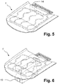
- Figures 5 and 6 show the hood 1 according to the present invention where the channel structure is connected to a battery pack 14 and an internal combustion engine 13, respectively.
- the inner panel could constitute the vehicle body inner side portion of the hood.
- the inner panel comprises ridge portions which swell toward the outer panel such that the ridge portions accommodate the conduits 11 such that when complete, the conduits are covered by the ridge portions.
- the ridge portions should then be formed from a vehicle body front side to a vehicle body rear side at predetermined intervals in a vehicle transverse direction such that they cover the conduits 11.
- a further alternative is to use circular conduits instead of the ones shown in figure 4b where the heat conductive joint instead would have to be bigger to maximize the contact area with the panel and thus the heat transfer between the panel and the conduits.
Abstract
Description
- The present invention relates to a hood for closing a compartment of a vehicle. The hood comprises an outer panel forming a vehicle body outer side portion of the hood.
- In the field of cooling there are several approaches, the most common being the cooling with a front cooler for cooling the engine. Also, in order to cool the engine bay, openings in the hood have been used to convey air into the engine bay and using convection cooling. With electric vehicles and hybrids with a battery that can be charged with a cable connection, there is sometimes a need for cooling of the battery.
- Electric vehicles use large batteries to store energy. The energy flowing into the battery pack as it is charged either from regenerative braking or from the grid and discharged from the pack to power the vehicle and its accessories is measured by electrical current and voltage. The flow of current causes heating in the battery cells and their interconnection systems proportional to the square of the current flowing multiplied by the internal resistance of the cells and the interconnect systems. The higher the current flow the more the heating effect will be.
- The performance of Lithium Ion battery cells is greatly impacted by their temperature, they suffer from the Goldilocks effect, they do not perform well when too cold or too hot, which can lead to permanent and extreme damage of the cells or accelerated degradation. Most lithium battery cells begin to degrade quickly when their temperature is above 45 Celsius.
- In the past the largest battery packs did not necessarily need any special cooling as the physical size of the packs was sufficient and the relative flow of current was not large compared to the overall capacity of the pack. As ever faster battery charging rates are demanded with recharge power of over 200kW to deliver times of 30 minutes or less, higher performance electric vehicles with a requirement for consistent performance and adequate durability in global markets has meant that special thermal management methods for the battery pack are now required. There are 3 common battery thermal management methods used today; convection to air either passively or forced, cooling by flooding the battery with a dielectric oil which is then pumped out to a heat exchanger system, and cooling by circulation of water based coolant through cooling passages within the battery structure.
- It is an object of the present invention to provide an alternative cooling system that has a decreased use of power compared to the cooling systems of present art.
- According to a first aspect of the present disclosure there is provided a hood for closing a compartment of a vehicle, wherein the hood comprises an outer panel forming a vehicle body outer side portion of the hood. The hood comprises a cooling channel structure arranged at an inner side portion of the outer panel. The cooling channel structure is adapted for transferring a cooling fluid from a vehicle component and back to the vehicle component such that heat is exchanged via the outer panel with the vehicle surroundings. The heat exchange is mainly due to convection if the vehicle is moving and mainly heat radiation if the vehicle is not moving.
- According to one aspect of the present disclosure the cooling channel structure extends over a main part of the outer panel. The channel structure is arranged to be evenly distributed over the outer panel. In the case of one channel it is arranged such that it goes back and forth over the outer panel with equal distance between the parallel parts of the channel. In the case of more channels, for instance if the channel structure is such that one channel is forked into two or more channels, the channel parts are equally distanced where they are parallel to one another.
- According to a further aspect of the present disclosure the cooling channel structure comprises a plurality of spaced first channel portions extending in a first direction.
- The first direction is according to another aspect of the present disclosure commensurate with a direction between front side of the hood and a rear side of the hood and wherein the first channel portions are spaced in a hood transverse direction.
- In an alternative aspect of the present disclosure the cooling channel structure comprises a plurality of spaced second channel portions extending in a second direction transverse relative to the first direction. A further possibility is that the second direction is commensurate with a transverse direction of the hood and that the first channel portions are spaced in a hood forward direction.
- According to a further aspect of the present disclosure the first channel portions are in fluid communication with the second channel portions.
- In yet another aspect of the present disclosure the cooling channel structure comprises an inlet and an outlet arranged at a first side of the hood.
- According to yet another aspect of the present disclosure the hood comprises at least one hood hinge element for pivoting the hood between an open position and a closed position and wherein the hinge element is arranged at the first side of the hood. This minimizes the length of the connections required.
- According to a preferred aspect of the present disclosure the cooling channel structure is arranged such that the flow of coolant liquid is divided into at least two flows after the inlet and merged into one flow upstream the outlet.
- In another aspect of the present disclosure the cooling channel structure is at least partly made of aluminum.
- Further, according to another aspect of the present disclosure the cooling channel structure is directly attached to an inner side surface of the outer panel.
- The cooling channel structure is according to a further aspect of the present disclosure attached to an inner side surface of the outer panel with a heat conducting joint. The joint could for instance be an adhesive or a welded/soldered joint.
- According to one aspect of the present disclosure a vehicle comprises at least one vehicle component, which in an operational state is in need of heat exchange, and a hood according to the above disclosure, wherein the vehicle component is adapted to be fluidly connected to the cooling channel structure in a way forming a cooling loop. One example of a vehicle component is an internal combustion engine. Another example is a battery pack
- Further features of, and advantages with, the present invention will become apparent when studying the appended claims and the following description. The skilled person realize that different features of the present invention may be combined to create embodiments other than those described in the following, without departing from the scope of the present invention.
- The above, as well as additional objects, features and advantages of the present invention, will be better understood through the following illustrative and non-limiting detailed description of exemplary embodiments of the present invention, wherein:
-
Fig. 1 is a perspective view of a front part of a vehicle. -
Fig. 2 is a perspective view of a vehicle hood. -
Fig. 3a is a perspective view of an underside of a vehicle hood. -
Fig. 3b is a view of the section A-A infigure 3a . -
Fig. 4a is perspective view of an underside of a vehicle hood. -
Fig. 4b is a view of the section B-B infigure 4a . -
Fig. 5 is a partial perspective view of a hood connected to a battery. -
Fig. 6 is a partial perspective view of a hood connected to an internal combustion engine. - The present invention will now be described more fully hereinafter with reference to the accompanying drawings, in which exemplary embodiments of the invention are shown. The invention may, however, be embodied in many different forms and should not be construed as limited to the embodiments set forth herein; rather, these embodiments are provided for thoroughness and completeness. Like reference character refer to like elements throughout the description.
- With reference to
figure 1 avehicle 2 is shown having ahood 1.Figure 2 shows the top side of anouter panel 4 of ahood 1. - Turning to
figures 3a and 3b , anengine hood 1 for a vehicle comprising at least onehood hinge element 3 and anouter panel 4 is shown. The outer panel constitutes the vehicle body outer side portion of thehood 1. A coolingliquid system 5 is arranged in a loop on theinner side portion 6 of theouter panel 4 of thehood 1 with an inlet 7 and anoutlet 8 of the loop arranged on the hingedside 9 of thehood 1. - The cooling
liquid system 5 utilizes an inner panel constituting a vehicle body inner side portion of the hood, wherein the inner panel comprisesridge portions 10 which swell toward the outer panel, i.e. they are wider at the outer panel in order to maximize the contact area and thus the heat conduction, such that theridge portions 10 accommodate the coolingliquid system 5. - The
ridge portions 10 are formed from a vehicle body front side to a vehicle body rear side at predetermined intervals in a vehicle transverse direction. - As can be seen in
figures 3a and 3b the ridge portions constitute the channels orconduits 10 conveying the cooling liquid. An advantage with this solution is that contact area between coolant and the panel is large in a natural way. - The loop is arranged such that the flow of coolant liquid is divided into at least two flows after the inlet 7 and merged into one flow upstream the
outlet 8. - Turning to
figures 4a and 4b , anengine hood 1 for avehicle 2 is shown comprising at least onehood hinge element 3 and anouter panel 4, the outer panel constituting the vehicle body outer side portion of thehood 1. A coolingliquid system 5 is arranged in a loop on theinner side portion 6 of theouter panel 4 of thehood 1 with an inlet 7 and anoutlet 8 of the loop arranged on the hingedside 9 of thehood 1. - Compared to the previous example channels or
conduits 11 here convey the cooling liquid. Theconduits 11 are attached to theouter panel 4 with a heat conducting joint 12. The contact area with theouter panel 4 should be as large as possible in order to maximize the heat conduction. An advantage with this solution is that the conduits is a closed separate system with minimal risk of leakage. - The loop is arranged such that the flow of coolant liquid is divided into at least two flows after the inlet 7 and merged into one flow upstream the
outlet 8. - Should the cooling loop in the hood be used during driving, as can be seen in
figures 3a and4a , the coolant flow could advantageously be arranged such that there will be a counter current heat exchange with the oncoming air, at least for most of the loop. -
Figures 5 and 6 show thehood 1 according to the present invention where the channel structure is connected to abattery pack 14 and aninternal combustion engine 13, respectively. - It is to be understood that the present invention is not limited to the embodiments described above and illustrated in the drawings; rather, the skilled person will recognize that many changes and modifications may be made within the scope of the appended claims. For example, in the drawings the coolant flow is divided utilizing a sort of manifold. There could be instances where a single conduit is used.
- According to another aspect of the disclosed system it could under certain weather conditions also be used for heating purposes.
- Further, the inner panel could constitute the vehicle body inner side portion of the hood. According to one example the inner panel comprises ridge portions which swell toward the outer panel such that the ridge portions accommodate the
conduits 11 such that when complete, the conduits are covered by the ridge portions. The ridge portions should then be formed from a vehicle body front side to a vehicle body rear side at predetermined intervals in a vehicle transverse direction such that they cover theconduits 11. - A further alternative is to use circular conduits instead of the ones shown in
figure 4b where the heat conductive joint instead would have to be bigger to maximize the contact area with the panel and thus the heat transfer between the panel and the conduits.
Claims (15)
- A hood (1) for closing a compartment of a vehicle (2), wherein the hood (1) comprises an outer panel (4) forming a vehicle body outer side portion of the hood (1),
characterized in
that the hood comprises a cooling channel structure (5) arranged at an inner side portion (6) of the outer panel (4), that the cooling channel structure (5) is adapted for transferring a cooling fluid from a vehicle component and back to the vehicle component such that heat is exchanged via the outer panel with the vehicle surroundings. - The hood (1) according to claim 1, wherein the cooling channel structure comprises a plurality of spaced first channel portions (10) extending in a first direction.
- The hood according to claim 2, wherein the first direction is commensurate with a direction between front side of the hood and a rear side of the hood and wherein the first channel portions (10) are spaced in a hood transverse direction.
- The hood (1) according to claim 2 or 3, wherein the cooling channel structure comprises a plurality of spaced second channel portions extending in a second direction transverse relative to the first direction.
- The hood (1) according to claim 4, wherein the second direction is commensurate with a transverse direction of the hood and that the first channel portions (10) are spaced in a hood forward direction.
- The hood (1) according to any one of claims 2 to 3 and any one of claims 4 to 5, wherein the first channel portions (10) are in fluid communication with the second channel portions.
- The hood (1) according to any of the preceding claims, wherein the cooling channel structure comprises an inlet (7) and an outlet (8) arranged at a first side (9) of the hood (1).
- The hood (1) according to claim 7, wherein the hood (1) comprises at least one hood hinge element (3) for pivoting the hood between an open position and a closed position and wherein the hinge element (3) is arranged at the first side (9) of the hood (1).
- The hood (1) according to claim 7 or 8, wherein the cooling channel structure is arranged such that the flow of coolant liquid is divided into at least two flows after the inlet (7) and merged into one flow upstream the outlet (8).
- The hood (1) according to any of the preceding claims, wherein the cooling channel structure is at least partly made of aluminum.
- The hood (1) according to any of the preceding claims, wherein the cooling channel structure is directly attached to an inner side surface of the outer panel (4).
- The hood (1) according to any of the preceding claims, wherein the cooling channel structure is attached to an inner side surface of the outer panel (4) with a heat conducting joint (12).
- A vehicle comprising at least one vehicle component, which in an operational state is in need of heat exchange, and a hood (1) according to any of the preceding claims, wherein the vehicle component is adapted to be fluidly connected to the cooling channel structure (5) in a way forming a cooling loop.
- A vehicle according to claim 13, wherein the vehicle component is formed by an internal combustion engine (13).
- A vehicle according to claim 13 or 14, wherein the vehicle component is formed by a battery pack (14).
Priority Applications (4)
| Application Number | Priority Date | Filing Date | Title |
|---|---|---|---|
| EP18168767.4A EP3560799B1 (en) | 2018-04-23 | 2018-04-23 | Hood |
| CN201980026807.3A CN111989255A (en) | 2018-04-23 | 2019-04-12 | Hood |
| PCT/CN2019/082395 WO2019205958A1 (en) | 2018-04-23 | 2019-04-12 | Hood |
| US17/074,437 US11702143B2 (en) | 2018-04-23 | 2020-10-19 | Hood |
Applications Claiming Priority (1)
| Application Number | Priority Date | Filing Date | Title |
|---|---|---|---|
| EP18168767.4A EP3560799B1 (en) | 2018-04-23 | 2018-04-23 | Hood |
Publications (2)
| Publication Number | Publication Date |
|---|---|
| EP3560799A1 true EP3560799A1 (en) | 2019-10-30 |
| EP3560799B1 EP3560799B1 (en) | 2021-12-29 |
Family
ID=62046753
Family Applications (1)
| Application Number | Title | Priority Date | Filing Date |
|---|---|---|---|
| EP18168767.4A Active EP3560799B1 (en) | 2018-04-23 | 2018-04-23 | Hood |
Country Status (4)
| Country | Link |
|---|---|
| US (1) | US11702143B2 (en) |
| EP (1) | EP3560799B1 (en) |
| CN (1) | CN111989255A (en) |
| WO (1) | WO2019205958A1 (en) |
Families Citing this family (3)
| Publication number | Priority date | Publication date | Assignee | Title |
|---|---|---|---|---|
| US11286005B2 (en) * | 2019-09-03 | 2022-03-29 | Honda Motor Co., Ltd. | Hood frame reinforcement for deflection mitigation |
| CN112644588B (en) * | 2020-12-21 | 2022-11-15 | 江苏班德智能制造有限公司 | New energy automobile front hood |
| FR3134757A1 (en) | 2022-04-22 | 2023-10-27 | IFP Energies Nouvelles | Vehicle with cooling system including a cold plate |
Citations (4)
| Publication number | Priority date | Publication date | Assignee | Title |
|---|---|---|---|---|
| JPS61150824A (en) * | 1984-12-25 | 1986-07-09 | Isuzu Motors Ltd | Car engine cooling device |
| DE10337869A1 (en) * | 2003-08-18 | 2005-03-17 | Volkswagen Ag | Radiator device esp. for IC engine of motor vehicles has heat exchange area formed on engine bonnet, with honeycomb-structure alternating cooling sections, having good impact energy consumption |
| FR2909595A3 (en) * | 2006-12-12 | 2008-06-13 | Renault Sas | Heat regulating system for heat engine of motor vehicle, has exchanger with exchanging wall exchanging heat with air to form external face of vehicle body, where temperature of exchanger is limited to lower level of specific degree Celsius |
| DE102008022288A1 (en) * | 2008-04-28 | 2009-10-29 | Deutsches Zentrum für Luft- und Raumfahrt e.V. | Vehicle body for vehicle, has support structure and outer structure, which is arranged at support structure, where energy absorption device is formed by throughflow device |
Family Cites Families (14)
| Publication number | Priority date | Publication date | Assignee | Title |
|---|---|---|---|---|
| US2489750A (en) * | 1947-01-10 | 1949-11-29 | Southern States Equipment Corp | Electric switch |
| JP2007331440A (en) * | 2006-06-12 | 2007-12-27 | Toyota Motor Corp | Vehicle front part structure |
| US8892314B2 (en) | 2011-06-15 | 2014-11-18 | GM Global Technology Operations LLC | Rejection of under-hood airflow |
| US10190480B2 (en) * | 2013-01-24 | 2019-01-29 | Ford Global Technologies, Llc | Engine cover plate |
| CN104879172A (en) * | 2015-06-01 | 2015-09-02 | 靖江市新程汽车零部件有限公司 | Automobile engine heat-insulating protection cover |
| CN204915846U (en) * | 2015-07-26 | 2015-12-30 | 南安智能蓝工业设计有限公司 | Do benefit to radiating bonnet of engine |
| CN205686479U (en) * | 2016-06-13 | 2016-11-16 | 南安智能蓝工业设计有限公司 | A kind of water-cooling bonnet |
| CN205801264U (en) * | 2016-07-17 | 2016-12-14 | 漳州妹族工业设计有限公司 | A kind of automobile engine cover with noise abatement cooling function |
| CN106252687A (en) * | 2016-09-13 | 2016-12-21 | 广东工业大学 | A kind of fuel battery reaction device |
| CN106864603A (en) * | 2017-03-20 | 2017-06-20 | 无锡市龙海杰机械制造有限公司 | Efficient exhausting heat radiation type automobile engine cover |
| CN107310632A (en) * | 2017-06-27 | 2017-11-03 | 山东国金汽车制造有限公司 | A kind of Engine Casing for being easy to noise reduction heat-insulated |
| US10556482B2 (en) * | 2017-09-15 | 2020-02-11 | GM Global Technology Operations LLC | Vascular structures and methods for thermal control |
| US10155547B1 (en) * | 2017-09-15 | 2018-12-18 | GM Global Technology Operations LLC | Vascular structures and methods for heat management |
| CN107745750A (en) * | 2017-11-25 | 2018-03-02 | 成都顺宏鑫机械有限公司 | Bonnet with heat sinking function |
-
2018
- 2018-04-23 EP EP18168767.4A patent/EP3560799B1/en active Active
-
2019
- 2019-04-12 WO PCT/CN2019/082395 patent/WO2019205958A1/en active Application Filing
- 2019-04-12 CN CN201980026807.3A patent/CN111989255A/en active Pending
-
2020
- 2020-10-19 US US17/074,437 patent/US11702143B2/en active Active
Patent Citations (4)
| Publication number | Priority date | Publication date | Assignee | Title |
|---|---|---|---|---|
| JPS61150824A (en) * | 1984-12-25 | 1986-07-09 | Isuzu Motors Ltd | Car engine cooling device |
| DE10337869A1 (en) * | 2003-08-18 | 2005-03-17 | Volkswagen Ag | Radiator device esp. for IC engine of motor vehicles has heat exchange area formed on engine bonnet, with honeycomb-structure alternating cooling sections, having good impact energy consumption |
| FR2909595A3 (en) * | 2006-12-12 | 2008-06-13 | Renault Sas | Heat regulating system for heat engine of motor vehicle, has exchanger with exchanging wall exchanging heat with air to form external face of vehicle body, where temperature of exchanger is limited to lower level of specific degree Celsius |
| DE102008022288A1 (en) * | 2008-04-28 | 2009-10-29 | Deutsches Zentrum für Luft- und Raumfahrt e.V. | Vehicle body for vehicle, has support structure and outer structure, which is arranged at support structure, where energy absorption device is formed by throughflow device |
Also Published As
| Publication number | Publication date |
|---|---|
| WO2019205958A1 (en) | 2019-10-31 |
| US20210031838A1 (en) | 2021-02-04 |
| CN111989255A (en) | 2020-11-24 |
| US11702143B2 (en) | 2023-07-18 |
| EP3560799B1 (en) | 2021-12-29 |
Similar Documents
| Publication | Publication Date | Title |
|---|---|---|
| US11702143B2 (en) | Hood | |
| US10109897B2 (en) | Battery thermal management system for electrified vehicle | |
| US10003112B1 (en) | Battery backplane assembly with integrated bus bar connections and thermal management features | |
| US11590855B2 (en) | Electric vehicle fast charging and battery cooling system using a charger cooled fluid-to-battery cooled fluid heat exchange device | |
| US20160190663A1 (en) | Busbars with integrated cooling system for vehicle battery assemblies | |
| KR101156958B1 (en) | Battery pack and battery pack assembly for electric vehicle and temperature control system using thereof | |
| EP3201966B1 (en) | Battery module thermal management fluid guide assembly | |
| CA2860465C (en) | Fluid-cooled battery module containing battery cells | |
| JP6099772B2 (en) | Battery pack with improved safety against outflow of liquid refrigerant | |
| US9819062B2 (en) | Traction battery assembly with thermal device | |
| US20140356652A1 (en) | Battery thermal management system for electrified vehicle | |
| CN104364961A (en) | Air cooled thermal management system for hev battery pack | |
| KR20130035192A (en) | Battery pack having novel cooling structure | |
| US9509018B2 (en) | Expanded battery cooling fin | |
| US9728826B2 (en) | Traction battery thermal management method and system | |
| CN108933309A (en) | Single pond module for electric vehicle and hybrid vehicle | |
| KR102371514B1 (en) | A Cooling/Heating Structure composed of cylindrical battery Cells | |
| CN105489966A (en) | Power battery pack | |
| CN110739425A (en) | vertical lithium battery pack air-cooling type thermal management system and method with high protection level | |
| JPH07329581A (en) | Battery heating device for electric vehicle | |
| CN211182455U (en) | Battery liquid cooling device | |
| CN216529034U (en) | Liquid cooling battery device, power battery and electrical equipment | |
| US20230318088A1 (en) | Temperature adjusting device and vehicle | |
| US20240113358A1 (en) | Battery pack thermal energy management assembly and thermal energy management method | |
| EP4320002A1 (en) | Electric drive vehicle |
Legal Events
| Date | Code | Title | Description |
|---|---|---|---|
| PUAI | Public reference made under article 153(3) epc to a published international application that has entered the european phase |
Free format text: ORIGINAL CODE: 0009012 |
|
| STAA | Information on the status of an ep patent application or granted ep patent |
Free format text: STATUS: REQUEST FOR EXAMINATION WAS MADE |
|
| 17P | Request for examination filed |
Effective date: 20180423 |
|
| AK | Designated contracting states |
Kind code of ref document: A1 Designated state(s): AL AT BE BG CH CY CZ DE DK EE ES FI FR GB GR HR HU IE IS IT LI LT LU LV MC MK MT NL NO PL PT RO RS SE SI SK SM TR |
|
| AX | Request for extension of the european patent |
Extension state: BA ME |
|
| GRAP | Despatch of communication of intention to grant a patent |
Free format text: ORIGINAL CODE: EPIDOSNIGR1 |
|
| STAA | Information on the status of an ep patent application or granted ep patent |
Free format text: STATUS: GRANT OF PATENT IS INTENDED |
|
| RIC1 | Information provided on ipc code assigned before grant |
Ipc: B62D 25/10 20060101AFI20210630BHEP Ipc: B62D 25/12 20060101ALI20210630BHEP Ipc: B60K 11/02 20060101ALI20210630BHEP Ipc: B60K 11/04 20060101ALI20210630BHEP |
|
| INTG | Intention to grant announced |
Effective date: 20210719 |
|
| GRAS | Grant fee paid |
Free format text: ORIGINAL CODE: EPIDOSNIGR3 |
|
| GRAA | (expected) grant |
Free format text: ORIGINAL CODE: 0009210 |
|
| STAA | Information on the status of an ep patent application or granted ep patent |
Free format text: STATUS: THE PATENT HAS BEEN GRANTED |
|
| AK | Designated contracting states |
Kind code of ref document: B1 Designated state(s): AL AT BE BG CH CY CZ DE DK EE ES FI FR GB GR HR HU IE IS IT LI LT LU LV MC MK MT NL NO PL PT RO RS SE SI SK SM TR |
|
| REG | Reference to a national code |
Ref country code: GB Ref legal event code: FG4D |
|
| REG | Reference to a national code |
Ref country code: CH Ref legal event code: EP |
|
| REG | Reference to a national code |
Ref country code: AT Ref legal event code: REF Ref document number: 1458489 Country of ref document: AT Kind code of ref document: T Effective date: 20220115 |
|
| REG | Reference to a national code |
Ref country code: IE Ref legal event code: FG4D |
|
| REG | Reference to a national code |
Ref country code: DE Ref legal event code: R096 Ref document number: 602018028696 Country of ref document: DE |
|
| REG | Reference to a national code |
Ref country code: LT Ref legal event code: MG9D |
|
| PG25 | Lapsed in a contracting state [announced via postgrant information from national office to epo] |
Ref country code: RS Free format text: LAPSE BECAUSE OF FAILURE TO SUBMIT A TRANSLATION OF THE DESCRIPTION OR TO PAY THE FEE WITHIN THE PRESCRIBED TIME-LIMIT Effective date: 20211229 Ref country code: LT Free format text: LAPSE BECAUSE OF FAILURE TO SUBMIT A TRANSLATION OF THE DESCRIPTION OR TO PAY THE FEE WITHIN THE PRESCRIBED TIME-LIMIT Effective date: 20211229 Ref country code: FI Free format text: LAPSE BECAUSE OF FAILURE TO SUBMIT A TRANSLATION OF THE DESCRIPTION OR TO PAY THE FEE WITHIN THE PRESCRIBED TIME-LIMIT Effective date: 20211229 Ref country code: BG Free format text: LAPSE BECAUSE OF FAILURE TO SUBMIT A TRANSLATION OF THE DESCRIPTION OR TO PAY THE FEE WITHIN THE PRESCRIBED TIME-LIMIT Effective date: 20220329 |
|
| REG | Reference to a national code |
Ref country code: NL Ref legal event code: MP Effective date: 20211229 |
|
| REG | Reference to a national code |
Ref country code: AT Ref legal event code: MK05 Ref document number: 1458489 Country of ref document: AT Kind code of ref document: T Effective date: 20211229 |
|
| PG25 | Lapsed in a contracting state [announced via postgrant information from national office to epo] |
Ref country code: SE Free format text: LAPSE BECAUSE OF FAILURE TO SUBMIT A TRANSLATION OF THE DESCRIPTION OR TO PAY THE FEE WITHIN THE PRESCRIBED TIME-LIMIT Effective date: 20211229 Ref country code: NO Free format text: LAPSE BECAUSE OF FAILURE TO SUBMIT A TRANSLATION OF THE DESCRIPTION OR TO PAY THE FEE WITHIN THE PRESCRIBED TIME-LIMIT Effective date: 20220329 Ref country code: LV Free format text: LAPSE BECAUSE OF FAILURE TO SUBMIT A TRANSLATION OF THE DESCRIPTION OR TO PAY THE FEE WITHIN THE PRESCRIBED TIME-LIMIT Effective date: 20211229 Ref country code: HR Free format text: LAPSE BECAUSE OF FAILURE TO SUBMIT A TRANSLATION OF THE DESCRIPTION OR TO PAY THE FEE WITHIN THE PRESCRIBED TIME-LIMIT Effective date: 20211229 |
|
| PG25 | Lapsed in a contracting state [announced via postgrant information from national office to epo] |
Ref country code: NL Free format text: LAPSE BECAUSE OF FAILURE TO SUBMIT A TRANSLATION OF THE DESCRIPTION OR TO PAY THE FEE WITHIN THE PRESCRIBED TIME-LIMIT Effective date: 20211229 |
|
| PG25 | Lapsed in a contracting state [announced via postgrant information from national office to epo] |
Ref country code: SM Free format text: LAPSE BECAUSE OF FAILURE TO SUBMIT A TRANSLATION OF THE DESCRIPTION OR TO PAY THE FEE WITHIN THE PRESCRIBED TIME-LIMIT Effective date: 20211229 Ref country code: SK Free format text: LAPSE BECAUSE OF FAILURE TO SUBMIT A TRANSLATION OF THE DESCRIPTION OR TO PAY THE FEE WITHIN THE PRESCRIBED TIME-LIMIT Effective date: 20211229 Ref country code: RO Free format text: LAPSE BECAUSE OF FAILURE TO SUBMIT A TRANSLATION OF THE DESCRIPTION OR TO PAY THE FEE WITHIN THE PRESCRIBED TIME-LIMIT Effective date: 20211229 Ref country code: PT Free format text: LAPSE BECAUSE OF FAILURE TO SUBMIT A TRANSLATION OF THE DESCRIPTION OR TO PAY THE FEE WITHIN THE PRESCRIBED TIME-LIMIT Effective date: 20220429 Ref country code: ES Free format text: LAPSE BECAUSE OF FAILURE TO SUBMIT A TRANSLATION OF THE DESCRIPTION OR TO PAY THE FEE WITHIN THE PRESCRIBED TIME-LIMIT Effective date: 20211229 Ref country code: EE Free format text: LAPSE BECAUSE OF FAILURE TO SUBMIT A TRANSLATION OF THE DESCRIPTION OR TO PAY THE FEE WITHIN THE PRESCRIBED TIME-LIMIT Effective date: 20211229 Ref country code: CZ Free format text: LAPSE BECAUSE OF FAILURE TO SUBMIT A TRANSLATION OF THE DESCRIPTION OR TO PAY THE FEE WITHIN THE PRESCRIBED TIME-LIMIT Effective date: 20211229 |
|
| PG25 | Lapsed in a contracting state [announced via postgrant information from national office to epo] |
Ref country code: PL Free format text: LAPSE BECAUSE OF FAILURE TO SUBMIT A TRANSLATION OF THE DESCRIPTION OR TO PAY THE FEE WITHIN THE PRESCRIBED TIME-LIMIT Effective date: 20211229 Ref country code: AT Free format text: LAPSE BECAUSE OF FAILURE TO SUBMIT A TRANSLATION OF THE DESCRIPTION OR TO PAY THE FEE WITHIN THE PRESCRIBED TIME-LIMIT Effective date: 20211229 |
|
| PG25 | Lapsed in a contracting state [announced via postgrant information from national office to epo] |
Ref country code: IS Free format text: LAPSE BECAUSE OF FAILURE TO SUBMIT A TRANSLATION OF THE DESCRIPTION OR TO PAY THE FEE WITHIN THE PRESCRIBED TIME-LIMIT Effective date: 20220429 |
|
| REG | Reference to a national code |
Ref country code: DE Ref legal event code: R097 Ref document number: 602018028696 Country of ref document: DE |
|
| PG25 | Lapsed in a contracting state [announced via postgrant information from national office to epo] |
Ref country code: DK Free format text: LAPSE BECAUSE OF FAILURE TO SUBMIT A TRANSLATION OF THE DESCRIPTION OR TO PAY THE FEE WITHIN THE PRESCRIBED TIME-LIMIT Effective date: 20211229 Ref country code: AL Free format text: LAPSE BECAUSE OF FAILURE TO SUBMIT A TRANSLATION OF THE DESCRIPTION OR TO PAY THE FEE WITHIN THE PRESCRIBED TIME-LIMIT Effective date: 20211229 |
|
| PLBE | No opposition filed within time limit |
Free format text: ORIGINAL CODE: 0009261 |
|
| STAA | Information on the status of an ep patent application or granted ep patent |
Free format text: STATUS: NO OPPOSITION FILED WITHIN TIME LIMIT |
|
| REG | Reference to a national code |
Ref country code: CH Ref legal event code: PL |
|
| 26N | No opposition filed |
Effective date: 20220930 |
|
| REG | Reference to a national code |
Ref country code: BE Ref legal event code: MM Effective date: 20220430 |
|
| PG25 | Lapsed in a contracting state [announced via postgrant information from national office to epo] |
Ref country code: MC Free format text: LAPSE BECAUSE OF FAILURE TO SUBMIT A TRANSLATION OF THE DESCRIPTION OR TO PAY THE FEE WITHIN THE PRESCRIBED TIME-LIMIT Effective date: 20211229 Ref country code: LI Free format text: LAPSE BECAUSE OF NON-PAYMENT OF DUE FEES Effective date: 20220430 Ref country code: CH Free format text: LAPSE BECAUSE OF NON-PAYMENT OF DUE FEES Effective date: 20220430 Ref country code: LU Free format text: LAPSE BECAUSE OF NON-PAYMENT OF DUE FEES Effective date: 20220423 |
|
| PG25 | Lapsed in a contracting state [announced via postgrant information from national office to epo] |
Ref country code: SI Free format text: LAPSE BECAUSE OF FAILURE TO SUBMIT A TRANSLATION OF THE DESCRIPTION OR TO PAY THE FEE WITHIN THE PRESCRIBED TIME-LIMIT Effective date: 20211229 Ref country code: BE Free format text: LAPSE BECAUSE OF NON-PAYMENT OF DUE FEES Effective date: 20220430 |
|
| PG25 | Lapsed in a contracting state [announced via postgrant information from national office to epo] |
Ref country code: IE Free format text: LAPSE BECAUSE OF NON-PAYMENT OF DUE FEES Effective date: 20220423 |
|
| PG25 | Lapsed in a contracting state [announced via postgrant information from national office to epo] |
Ref country code: IT Free format text: LAPSE BECAUSE OF FAILURE TO SUBMIT A TRANSLATION OF THE DESCRIPTION OR TO PAY THE FEE WITHIN THE PRESCRIBED TIME-LIMIT Effective date: 20211229 |
|
| PGFP | Annual fee paid to national office [announced via postgrant information from national office to epo] |
Ref country code: FR Payment date: 20230425 Year of fee payment: 6 Ref country code: DE Payment date: 20230412 Year of fee payment: 6 |
|
| PGFP | Annual fee paid to national office [announced via postgrant information from national office to epo] |
Ref country code: GB Payment date: 20230424 Year of fee payment: 6 |
|
| PG25 | Lapsed in a contracting state [announced via postgrant information from national office to epo] |
Ref country code: HU Free format text: LAPSE BECAUSE OF FAILURE TO SUBMIT A TRANSLATION OF THE DESCRIPTION OR TO PAY THE FEE WITHIN THE PRESCRIBED TIME-LIMIT; INVALID AB INITIO Effective date: 20180423 |