EP3560740A1 - Method and device for fitting a vehicle rail - Google Patents
Method and device for fitting a vehicle rail Download PDFInfo
- Publication number
- EP3560740A1 EP3560740A1 EP19155641.4A EP19155641A EP3560740A1 EP 3560740 A1 EP3560740 A1 EP 3560740A1 EP 19155641 A EP19155641 A EP 19155641A EP 3560740 A1 EP3560740 A1 EP 3560740A1
- Authority
- EP
- European Patent Office
- Prior art keywords
- vehicle window
- frame
- adhesive
- gap
- edge
- Prior art date
- Legal status (The legal status is an assumption and is not a legal conclusion. Google has not performed a legal analysis and makes no representation as to the accuracy of the status listed.)
- Granted
Links
- 238000000034 method Methods 0.000 title claims description 19
- 239000000853 adhesive Substances 0.000 claims abstract description 62
- 230000001070 adhesive effect Effects 0.000 claims abstract description 62
- 229920002635 polyurethane Polymers 0.000 claims description 2
- 239000004814 polyurethane Substances 0.000 claims description 2
- 238000009434 installation Methods 0.000 abstract description 4
- 239000011324 bead Substances 0.000 description 10
- 238000007789 sealing Methods 0.000 description 4
- 238000003780 insertion Methods 0.000 description 2
- 230000037431 insertion Effects 0.000 description 2
- 230000004048 modification Effects 0.000 description 2
- 238000012986 modification Methods 0.000 description 2
- 239000013466 adhesive and sealant Substances 0.000 description 1
- 238000004026 adhesive bonding Methods 0.000 description 1
- 238000013459 approach Methods 0.000 description 1
- 101150038956 cup-4 gene Proteins 0.000 description 1
- 230000000694 effects Effects 0.000 description 1
- 229920001971 elastomer Polymers 0.000 description 1
- 239000000806 elastomer Substances 0.000 description 1
- 239000004459 forage Substances 0.000 description 1
- 239000003292 glue Substances 0.000 description 1
- 230000001771 impaired effect Effects 0.000 description 1
- 230000035515 penetration Effects 0.000 description 1
- 229920003023 plastic Polymers 0.000 description 1
- 239000004033 plastic Substances 0.000 description 1
Images

Classifications
-
- B—PERFORMING OPERATIONS; TRANSPORTING
- B60—VEHICLES IN GENERAL
- B60J—WINDOWS, WINDSCREENS, NON-FIXED ROOFS, DOORS, OR SIMILAR DEVICES FOR VEHICLES; REMOVABLE EXTERNAL PROTECTIVE COVERINGS SPECIALLY ADAPTED FOR VEHICLES
- B60J1/00—Windows; Windscreens; Accessories therefor
- B60J1/004—Mounting of windows
-
- B—PERFORMING OPERATIONS; TRANSPORTING
- B62—LAND VEHICLES FOR TRAVELLING OTHERWISE THAN ON RAILS
- B62D—MOTOR VEHICLES; TRAILERS
- B62D65/00—Designing, manufacturing, e.g. assembling, facilitating disassembly, or structurally modifying motor vehicles or trailers, not otherwise provided for
- B62D65/02—Joining sub-units or components to, or positioning sub-units or components with respect to, body shell or other sub-units or components
- B62D65/06—Joining sub-units or components to, or positioning sub-units or components with respect to, body shell or other sub-units or components the sub-units or components being doors, windows, openable roofs, lids, bonnets, or weather strips or seals therefor
-
- B—PERFORMING OPERATIONS; TRANSPORTING
- B05—SPRAYING OR ATOMISING IN GENERAL; APPLYING FLUENT MATERIALS TO SURFACES, IN GENERAL
- B05C—APPARATUS FOR APPLYING FLUENT MATERIALS TO SURFACES, IN GENERAL
- B05C5/00—Apparatus in which liquid or other fluent material is projected, poured or allowed to flow on to the surface of the work
- B05C5/02—Apparatus in which liquid or other fluent material is projected, poured or allowed to flow on to the surface of the work the liquid or other fluent material being discharged through an outlet orifice by pressure, e.g. from an outlet device in contact or almost in contact, with the work
- B05C5/0208—Apparatus in which liquid or other fluent material is projected, poured or allowed to flow on to the surface of the work the liquid or other fluent material being discharged through an outlet orifice by pressure, e.g. from an outlet device in contact or almost in contact, with the work for applying liquid or other fluent material to separate articles
- B05C5/0212—Apparatus in which liquid or other fluent material is projected, poured or allowed to flow on to the surface of the work the liquid or other fluent material being discharged through an outlet orifice by pressure, e.g. from an outlet device in contact or almost in contact, with the work for applying liquid or other fluent material to separate articles only at particular parts of the articles
Landscapes
- Engineering & Computer Science (AREA)
- Mechanical Engineering (AREA)
- Manufacturing & Machinery (AREA)
- Chemical & Material Sciences (AREA)
- Combustion & Propulsion (AREA)
- Transportation (AREA)
- Automobile Manufacture Line, Endless Track Vehicle, Trailer (AREA)
- Window Of Vehicle (AREA)
Abstract
Zum Montieren einer Fahrzeugscheibe (11) in einem Rahmen (21), der einen nach der Montage einer Hauptoberfläche (15) der Fahrzeugscheibe (11) gegenüberliegenden Rahmengrund (25) und eine einer Kante (12) der Fahrzeugscheibe (11) gegenüberliegende Rahmenflanke (26) umfasst, wirda) die Fahrzeugscheibe (11) am Rahmen (21)) unter Freihaltung eines ersten Spalts (31) zwischen der Hauptoberfläche (15) und dem Rahmengrund (25) platziert,b) ein Klebstoff in den ersten Spalt (31) eingebracht;c) die Fahrzeugscheibe (11) in Richtung des Rahmengrunds (25) zugestellt.For mounting a vehicle window (11) in a frame (21) which has a frame base (25) opposite after the installation of a main surface (15) of the vehicle window (11) and a frame flank (26) opposite an edge (12) of the vehicle window (11) ), a) the vehicle window (11) is placed on the frame (21)) while keeping a first gap (31) free between the main surface (15) and the frame base (25), b) an adhesive is introduced into the first gap (31) ; c) the vehicle window (11) advanced in the direction of the frame base (25).
Description
Die vorliegende Erfindung betrifft ein Verfahren und eine Vorrichtung zum Montieren einer Fahrzeugscheibe in einem Rahmen, typischerweise einem Fensterrahmen eines Fahrzeugs.The present invention relates to a method and apparatus for mounting a vehicle window in a frame, typically a window frame of a vehicle.
Die zum Einkleben einer Fahrzeugscheibe in einem Rahmen verwendeten Kleb- und Dichtstoffe müssen schnell härtend sein, um nach dem Platzieren der Fahrzeugscheibe am Rahmen eine Relativbewegung zwischen beiden zu verhindern, ohne dass ein zum Positionieren der Fahrzeugscheibe am Rahmen verwendetes Werkzeug nach dem Positionieren noch lange am Ort bleiben muss, sondern nach kurzer Zeit wieder verfügbar ist, um eine weitere Fahrzeugscheibe zu platzieren. Das schnelle Härten bringt es mit sich, dass die Oberfläche einer in herkömmlicher Weise auf dem Rand der Fahrzeugscheibe ausgebrachten Klebstoffraupe bereits begonnen hat, auszuhärten, bevor die Scheibe platziert werden kann. Wenn sich dann herausstellt, dass die Fahrzeugscheibe noch einmal bewegt werden muss, um z.B. eine einheitliche Spaltbreite zwischen den Kanten der Fahrzeugscheibe und gegenüberliegenden Flanken des Rahmens zu erreichen, dann kann eine solche Bewegung dazu führen, dass der Klebstoff sich vom Rahmen oder der Fahrzeugscheibe wieder ablöst und später keine dichte Verbindung zwischen Fahrzeugscheibe und Rahmen wieder zustande kommt.The adhesives and sealants used for gluing a vehicle window in a frame must be fast curing to prevent relative movement between the two after placing the vehicle window on the frame without a tool used to position the vehicle window on the frame after positioning for a long time Must remain place, but after a short time is available again to place another vehicle window. The rapid hardening entails that the surface of an adhesive bead conventionally applied to the edge of the vehicle window has already begun to set before the disk can be placed. If then it turns out that the vehicle window has to be moved again, for example, a uniform gap width between the edges of the vehicle window and opposite edges of the frame to reach, then such a movement can cause the adhesive to peel off the frame or the vehicle window again and later no tight connection between the vehicle window and frame comes about again.
Da der zweite Teilstrang im Innern des ersten vor Luftzutritt geschützt ist, bleibt er lange Zeit klebfähig und wird erst durch den Austritt aus dem ersten Teilstrang aktiviert.Since the second sub-string inside the first is protected from access of air, it remains sticky for a long time and is activated only by the exit from the first sub-strand.
Hier ergibt sich allerdings das Problem, eine sichere Klebung zwischen der Fahrzeugscheibe und dem ersten Teilstrang herzustellen. Die vorgeschlagene Verwendung eines Primers macht das Verfahren im Vergleich zur herkömmlichen Aufbringung einer Klebstoffraupe ohne innere Struktur kompliziert und aufwendig.Here, however, the problem arises to produce a secure bond between the vehicle window and the first sub-strand. The proposed use of a primer makes the process complicated and expensive compared to the conventional application of an adhesive bead without internal structure.
Aufgabe der vorliegenden Erfindung ist, ein Verfahren für eine einfache und wirtschaftliche Montage einer Fahrzeugscheibe und eine Vorrichtung zur Durchführung des Verfahrens zu schaffen.Object of the present invention is to provide a method for a simple and economical installation of a vehicle window and an apparatus for performing the method.
Die Aufgabe wird zum einen gelöst durch ein Verfahren zum Montieren einer Fahrzeugscheibe in einem Rahmen, der einen nach der Montage einer Hauptoberfläche der Fahrzeugscheibe gegenüberliegenden Rahmengrund und eine einer Kante der Fahrzeugscheibe gegenüberliegende Rahmenflanke umfasst, mit den Schritten
- a) Platzieren der Fahrzeugscheibe am Rahmen unter Freihaltung eines ersten Spalts zwischen der Hauptoberfläche und dem Rahmengrund,
- b) Einbringen eines Klebstoffs in den ersten Spalt;
- c) Zustellen der Fahrzeugscheibe in Richtung des Rahmengrunds.
- a) placing the vehicle window on the frame while leaving free a first gap between the main surface and the frame base,
- b) introducing an adhesive into the first gap;
- c) advancing the vehicle window in the direction of the frame ground.
Indem zuerst die Fahrzeugscheibe platziert und dann der Klebstoff eingebracht wird, wird zum einen die Zeitspanne verringert, die der Klebstoff der Luft ausgesetzt ist und in der er oberflächlich aushärten und sein Klebvermögen beeinträchtigt werden kann. Im Idealfall wird der Klebstoff so in den ersten Spalt eingebracht, dass die sich im Spalt bildende Klebstoffraupe bereits während des Einbringens in Kontakt sowohl mit der Fahrzeugscheibe als auch mit dem Rahmengrund kommt; so wird die Zeit, die ein Oberflächenabschnitt des Klebstoffs vor dem Inkontaktkommen mit der Fahrzeugscheibe oder dem Rahmengrund kommt, auf ein unvermeidliches Minimum beschränkt.By first placing the vehicle window and then applying the adhesive, on the one hand it reduces the amount of time that the adhesive is exposed to the air and in which it can be surface-hardened and its adhesiveness impaired. Ideally, the adhesive is introduced into the first gap such that the adhesive bead forming in the gap comes into contact with both the vehicle window and the frame base during insertion; thus, the time taken for a surface portion of the adhesive to come into contact with the vehicle window or frame is limited to an unavoidable minimum.
Zum anderen bietet der Schritt a) die Möglichkeit, die Fahrzeugscheibe vor dem Einbringen des Klebstoffs relativ zum Rahmen auszurichten, so dass z.B. den Abstand zwischen der Kante der Fahrzeugscheibe und der gegenüberliegenden Rahmenflanke rings um die Fahrzeugscheibe einheitlich einzustellen, so dass nach dem Einbringen des Klebstoffs die Fahrzeugscheibe ihre endgültige Position durch eine zum Rahmengrund senkrechte Zustellbewegung erreichen kann, d.h. der Klebstoff keiner oder allenfalls minimaler Scherverformung zwischen sich gegeneinander oberflächenparallel bewegenden Oberflächen der Fahrzeugscheibe und des Rahmengrunds ausgesetzt ist.On the other hand, the step a) offers the possibility to align the vehicle window relative to the frame prior to the introduction of the adhesive, so that For example, uniformly adjust the distance between the edge of the vehicle window and the opposite frame edge around the vehicle window, so that after the introduction of the adhesive, the vehicle window can reach its final position by a feed motion perpendicular to the frame base, ie the adhesive no or at most minimal shear deformation between them is exposed to surface-parallel moving surfaces of the vehicle window and the frame ground.
Vorzugsweise wird die Fahrzeugscheibe in Schritt a) bereits so tief in den Rahmen eingeführt, dass dadurch ein zweiter Spalt zwischen der Kante der Fahrzeugscheibe und der Rahmenflanke gebildet wird. Wie bereits oben angedeutet, kann die Breite des zweiten Spalts justiert und insbesondere rings um die Scheibe herum oder wenigstens zwischen einander gegenüberliegenden Kanten der Fahrzeugscheibe einheitlich gemacht werden, bevor der Klebstoff in den ersten Spalt eingebracht wird.Preferably, the vehicle window is already inserted so deeply into the frame in step a) that a second gap is thereby formed between the edge of the vehicle window and the frame edge. As already indicated above, the width of the second gap can be adjusted and, in particular, made uniform around the disc or at least between opposite edges of the vehicle window before the adhesive is introduced into the first gap.
Zum Einbringen des Klebstoffs in den ersten Spalt wird vorzugsweise eine in den zweiten Spalt eingreifende Düse verwendet. Eine solche Düse kann insbesondere zusammen mit einem Scheibenhalter Teil einer Vorrichtung zur Durchführung des Verfahrens sein, die dadurch, dass der Scheibenhalter die Scheibe im Rahmen platziert, zusammen mit diesem in eine Position gelangt, in der mit dem Einbringen des Klebstoffs in den ersten Spalt begonnen werden kann.For introducing the adhesive into the first gap, preferably a nozzle engaging in the second gap is used. In particular, such a nozzle, together with a disc holder, can be part of a device for carrying out the method, which, as a result of the disc holder placing the disc in the frame, arrives together with the latter in a position in which the adhesive is introduced into the first gap can be.
Um den Klebstoff entlang des ersten Spalts zu verteilen, sollte die Düse relativ zur Fahrzeugscheibe bzw. dem Scheibenhalter bewegbar sein. Zu diesem Zweck kann eine Führung, entlang derer die Düse bewegbar ist, mit dem Scheibenhalter zu einer Baueinheit verbunden sein.In order to distribute the adhesive along the first gap, the nozzle should be movable relative to the vehicle window or disk holder. For this purpose, a guide, along which the nozzle is movable, be connected to the disc holder to form a structural unit.
Um eine exakte Ausrichtung der Fahrzeugscheibe relativ zum Rahmen vor der Einbringung des Klebstoffs zu ermöglichen, sollte der Weg der auf die Einbringung des Klebstoffs folgenden Zustellbewegung kurz sein; insbesondere der zweite Spalt bereits vorhanden sein, oder die Breite des zweiten Spalts, die sich durch die Zustellbewegung ergibt, sollte bereits erkennbar sein. Deshalb ist bevorzugt, dass die Fahrzeugscheibe in der Zustellbewegung des Schritts c) einen Weg von maximal 5 mm, vorzugsweise maximal 3 mm, zurücklegt.In order to allow an exact alignment of the vehicle window relative to the frame prior to the introduction of the adhesive, the path of the delivery movement following the introduction of the adhesive should be short; In particular, the second gap already be present, or the width of the second gap, which results from the Zustellbewegung should already be apparent. Therefore, it is preferred that the vehicle window in the feed movement of step c) travels a maximum distance of 5 mm, preferably a maximum of 3 mm.
Andererseits sollte der erste Spalt nicht bereits zur Zeit des Schritts b) so eng sein, dass dadurch die Ausbreitung des Klebstoffs im ersten Spalt beeinträchtigt wird und insbesondere der Klebstoff durch die Zustellbewegung wieder aus dem ersten Spalt herausgedrängt wird, ohne ihn vollständig auszufüllen. Daher sollte der in der Zustellbewegung zurückgelegte Weg wenigstens einem Drittel der Breite des ersten Spalts zur Zeit des Schritts b) entsprechen.On the other hand, the first gap should not already be so tight at the time of step b) that this impairs the spread of the adhesive in the first gap and, in particular, that the adhesive is forced out of the first gap by the advancing movement without completely filling it. Therefore, the distance traveled in the feed motion should be at least one third of the width of the first gap at the time of step b).
Um einen festen Sitz der Fahrzeugscheibe garantieren zu können, sollte Klebstoff nicht nur im ersten Spalt vorhanden sein, sondern die Fahrzeugscheibe auch entlang ihrer Kanten umfangen. Zu diesem Zweck kann der Hub der Zustellbewegung bemessen sein, um Klebstoff aus dem ersten Spalt in den zweiten Spalt zu verdrängen.To be able to guarantee a secure fit of the vehicle window, adhesive should not only be present in the first gap, but should also surround the vehicle window along its edges. To this end For example, the stroke of the feed movement may be dimensioned to displace adhesive from the first gap into the second gap.
Als Klebstoff kommt insbesondere ein Polyurethanklebstoff wie etwa Sikaflex 268 in Betracht.A suitable adhesive is, in particular, a polyurethane adhesive such as Sikaflex 268.
Die Aufgabe wird zum anderen gelöst durch eine Vorrichtung zum Durchführen des oben beschriebenen Verfahrens, mit einem Scheibenhalter, der zur Durchführung der Bewegungen der Verfahrensschritte a) und c) in mehreren Freiheitsgraden bewegbar ist, und einer Düse zur Abgabe des Klebstoffs, die auf einer mit dem Scheibenhalter zu einer Baueinheit verbundenen Führung um den Scheibenhalter herum bewegbar ist.The object is achieved by another device for carrying out the method described above, with a disc holder, which is movable to perform the movements of the method steps a) and c) in several degrees of freedom, and a nozzle for dispensing the adhesive, on a with the disc holder to a unit connected to guide around the disc holder is movable.
Weitere Merkmale und Vorteile der Erfindung ergeben sich aus der nachfolgenden Beschreibung von Ausführungsbeispielen unter Bezugnahme auf die beigefügten Figuren. Es zeigen:
-
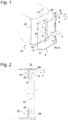
Fig. 1 eine perspektivische Ansicht einer Vorrichtung zur Durchführung des Verfahrens, bestückt mit einer Fahrzeugscheibe, und eines Rahmens, in dem die Fahrzeugscheibe montiert werden soll; -
Fig. 2 einen schematischen Schnitt durch den Rahmen und die darin platzierte Fahrzeugscheibe; -
Fig. 3 einen Schnitt durch den Rahmen und die Fahrzeugscheibe nach Einbringung des Klebstoffs in den ersten Spalt; -
Fig. 4 einen Schnitt durch den Rahmen und die Fahrzeugscheibe nach der Zustellbewegung. -
Fig. 5 einen zuFig. 3 analogen Schnitt gemäß einer ersten Abwandlung der Erfindung; und -
Fig. 6 einen zuFig. 3 analogen Schnitt gemäß einer zweiten Abwandlung.
-
Fig. 1 a perspective view of an apparatus for performing the method, equipped with a vehicle window, and a frame in which the vehicle window to be mounted; -
Fig. 2 a schematic section through the frame and the vehicle window placed therein; -
Fig. 3 a section through the frame and the vehicle window after introduction of the adhesive in the first gap; -
Fig. 4 a section through the frame and the vehicle window after the Zustellbewegung. -
Fig. 5 one tooFig. 3 analog section according to a first modification of the invention; and -
Fig. 6 one tooFig. 3 analog section according to a second modification.
Eine in
Ein äußerer Rahmen des Gestells 2 ist durch eine Schiene 5 gebildet, auf der ein Klebstoffdispenser 6 mit einer Düse 7 beweglich ist. Die Form der Schiene 5 ist dem Verlauf von Kanten 12 der Fahrzeugscheibe 11 nachgebildet, um die Düse 7, während der Klebstoffdispenser 6 auf der Schiene 5 umläuft, exakt an den Kanten 12 entlangführen zu können.An outer frame of the
Im in
Entsprechend der Wölbung der Fahrzeugscheibe 11 kann auch die Schiene 5 gekrümmte Abschnitte 8 im Übergangsbereich zwischen horizontalen und vertikalen Abschnitten aufweisen, und der Querschnitt der Schiene kann in den sich gegenüberliegenden vertikalen Abschnitten 9 jeweils gegeneinander verdreht sein, um eine entsprechende Verdrehung auch der Längsachse des Klebstoffdispensers 6 während seines Umlaufs auf der Schiene 5 zu erzwingen.Corresponding to the curvature of the vehicle window 11, the
Der Fahrzeugscheibe 1 gegenüberliegend ist in
Wie in
Im in
Die Breite des Spalts 32 ist ausreichend, um darin die Düse 7 einführen zu können und aus dieser Düse Klebstoff (siehe
Nachdem die Klebstoffraupe 33 entlang der Profile 22, 23, 24 durchgehend in den Spalt 31 eingebracht worden ist, wird durch eine Zustellbewegung des Roboterarms 4 der Spalt 31 verengt. Dies zwingt den noch plastischen Klebstoff, zu zwei Seiten hin auszuweichen und so einerseits den zunächst leer gebliebenen Teil 34 des Spalts 31 auszufüllen und andererseits in den Spalt 32 zwischen Kante 11 und Rahmenflanke 26 einzudringen. Da die Fahrzeugscheibe 11 somit auch in den zu ihrer Innenseite tangentialen Richtungen durch die Klebstoffraupe 33 in ihrer Beweglichkeit eingeschränkt ist, kann der Roboterarm 4 die Fahrzeugscheibe 11 noch vor dem vollständigen Aushärten des Klebstoffs freigeben und für die Montage einer weiteren Fahrzeugscheibe eingesetzt werden.After the
Im Falle der
Eine ähnliche Wirkung wird gemäß der in
Einer vereinfachten Ausgestaltung des Verfahrens zufolge ist die Platzierung der Fahrzeugscheibe 11 durch den Roboterarm 4 ersetzt durch eine manuelle Platzierung am Rahmen 21. Insbesondere bei dieser Ausgestaltung ist es wünschenswert, dass der Rahmen 21 einen nachgiebigen Anschlag wie etwa das Dichtprofil 28 aufweist, oder dass der Rahmenboden 25 selber in der Nähe der Innenkante 27 deformierbar ist, so dass die Fahrzeugscheibe 11 zunächst in einem ersten Abstand vom Rahmenboden 25 stabil positioniert werden kann und der Klebstoff in den dadurch offengehaltenen Spalt 31 eingebracht werden kann. Denkbar ist in diesem Fall auch, anstelle eines nachgiebigen Anschlags zunächst einen starren Anschlag von gleichem Querschnitt wie das Dichtprofil 28 auf den Rahmenboden 25 aufzustecken und diesen nach Einbringung des Klebstoffs zu entfernen, um dann die Fahrzeugscheibe 11 gegen den Rahmenboden 25 drücken und den Klebstoff zur Ausbreitung im Spalt 31 zwingen zu können.According to a simplified embodiment of the method, the placement of the vehicle window 11 replaced by the
Die Einbringung des Klebstoffs kann in diesem Fall mittels eines von Hand geführten oder eines maschinell geführten Dispensers 6 erfolgen.The introduction of the adhesive can be done in this case by means of a hand-guided or a machine-guided
- 11
- Bestückungsvorrichtungmounter
- 22
- Gestellframe
- 33
- Saugnapfsuction cup
- 44
- Roboterarmrobot arm
- 55
- Schienerail
- 66
- KlebstoffdispenserKlebstoffdispenser
- 77
- Düsejet
- 1111
- Fahrzeugscheibevehicle window
- 1212
- Kanteedge
- 1313
- gekrümmter Bereichcurved area
- 1414
- mittlerer Bereichmiddle area
- 1515
- Kanteedge
- 2121
- Rahmenframe
- 2222
- Profilprofile
- 2323
- Profilprofile
- 2424
- Profilprofile
- 2525
- Rahmengrundframe ground
- 2626
- Rahmenflankeframe edge
- 2727
- Innenkanteinner edge
- 2828
- Dichtprofilsealing profile
- 3131
- erster Spaltfirst gap
- 3232
- zweiter Spaltsecond gap
- 3333
- Klebstoffraupeadhesive bead
- 3434
- leerer Teilempty part
Claims (8)
Applications Claiming Priority (1)
| Application Number | Priority Date | Filing Date | Title |
|---|---|---|---|
| DE102018002898.5A DE102018002898A1 (en) | 2018-04-09 | 2018-04-09 | Method and device for mounting a vehicle window |
Publications (2)
| Publication Number | Publication Date |
|---|---|
| EP3560740A1 true EP3560740A1 (en) | 2019-10-30 |
| EP3560740B1 EP3560740B1 (en) | 2021-01-06 |
Family
ID=65351887
Family Applications (1)
| Application Number | Title | Priority Date | Filing Date |
|---|---|---|---|
| EP19155641.4A Active EP3560740B1 (en) | 2018-04-09 | 2019-02-06 | Method and device for fitting a vehicle rail |
Country Status (2)
| Country | Link |
|---|---|
| EP (1) | EP3560740B1 (en) |
| DE (1) | DE102018002898A1 (en) |
Citations (7)
| Publication number | Priority date | Publication date | Assignee | Title |
|---|---|---|---|---|
| US4841698A (en) * | 1988-06-15 | 1989-06-27 | Peter Gold | Automotive window retention system and retention element therefor |
| EP0351369B1 (en) | 1988-07-15 | 1991-09-11 | Gurit-Essex AG | Vehicle window for direct glazing, method of its manufacture and its use as ready-to-mount unit |
| EP0707937A1 (en) * | 1994-10-17 | 1996-04-24 | Saint-Gobain Vitrage | Device for extruding a polymer frame onto a plate-shaped object |
| DE112008001607T5 (en) * | 2007-06-15 | 2010-04-29 | Scania Cv Ab (Publ) | Method for fixing a window pane |
| FR2959475A1 (en) * | 2010-05-03 | 2011-11-04 | Peugeot Citroen Automobiles Sa | Windscreen assembling method for e.g. groove of motor vehicle, involves plating pane against wedging device until cord is hardened, where suction pad of wedging device is intended to retain pane as soon as pane is affixed on groove |
| FR2963757A1 (en) * | 2010-08-12 | 2012-02-17 | Peugeot Citroen Automobiles Sa | Method for mounting glazing pane i.e. windscreen, on e.g. structural rebate of motor vehicle, involves forming vent hole in contact with rebate, and forming another vent hole in contact with glazing pane |
| US20130092324A1 (en) * | 2011-03-04 | 2013-04-18 | Siegfried Dietz | Joining Surface Treatment Device and Method |
-
2018
- 2018-04-09 DE DE102018002898.5A patent/DE102018002898A1/en not_active Withdrawn
-
2019
- 2019-02-06 EP EP19155641.4A patent/EP3560740B1/en active Active
Patent Citations (7)
| Publication number | Priority date | Publication date | Assignee | Title |
|---|---|---|---|---|
| US4841698A (en) * | 1988-06-15 | 1989-06-27 | Peter Gold | Automotive window retention system and retention element therefor |
| EP0351369B1 (en) | 1988-07-15 | 1991-09-11 | Gurit-Essex AG | Vehicle window for direct glazing, method of its manufacture and its use as ready-to-mount unit |
| EP0707937A1 (en) * | 1994-10-17 | 1996-04-24 | Saint-Gobain Vitrage | Device for extruding a polymer frame onto a plate-shaped object |
| DE112008001607T5 (en) * | 2007-06-15 | 2010-04-29 | Scania Cv Ab (Publ) | Method for fixing a window pane |
| FR2959475A1 (en) * | 2010-05-03 | 2011-11-04 | Peugeot Citroen Automobiles Sa | Windscreen assembling method for e.g. groove of motor vehicle, involves plating pane against wedging device until cord is hardened, where suction pad of wedging device is intended to retain pane as soon as pane is affixed on groove |
| FR2963757A1 (en) * | 2010-08-12 | 2012-02-17 | Peugeot Citroen Automobiles Sa | Method for mounting glazing pane i.e. windscreen, on e.g. structural rebate of motor vehicle, involves forming vent hole in contact with rebate, and forming another vent hole in contact with glazing pane |
| US20130092324A1 (en) * | 2011-03-04 | 2013-04-18 | Siegfried Dietz | Joining Surface Treatment Device and Method |
Also Published As
| Publication number | Publication date |
|---|---|
| EP3560740B1 (en) | 2021-01-06 |
| DE102018002898A1 (en) | 2019-10-10 |
Similar Documents
| Publication | Publication Date | Title |
|---|---|---|
| EP1597121B1 (en) | Method for producing a wiper blade, device for carrying out said method and wiper blade produced according to said method | |
| EP2127838B1 (en) | Device for positioning and blocking thin substrates on a cut substrate block | |
| DE10335396A1 (en) | Method for producing a wiper blade and device for carrying out the method and wiper blade produced thereafter | |
| WO2017207410A1 (en) | Cleaning head as well as device and method for cleaning printing heads | |
| EP3442779A1 (en) | Method and device for joining two ends of a rubber profile | |
| EP2961907B1 (en) | Method and device for filling an edge joint of an insulating glass element with a sealing compound | |
| EP3741528A1 (en) | Device for coating a surface and method for coating a surface | |
| DE3808443A1 (en) | Method and device for adhesively bonding pliable, strand-like profiles | |
| DE102017202520A1 (en) | Method and device for connecting two sealing ends in a joint area | |
| EP2045054B1 (en) | Device for clamping and processing the end of a conveyor belt and method | |
| EP3560740B1 (en) | Method and device for fitting a vehicle rail | |
| EP2505269A2 (en) | Device for gluing a moved cover strip for rod-shaped products for the tobacco processing industry and assembly with such a device | |
| EP2476852A2 (en) | Assembly aid for a leaf of a door, window or the like | |
| EP3081356A1 (en) | Method for producing a partially harden wood fiberboard, partially solidified wood fiberboard, apparatus for producing the same | |
| EP3277605A1 (en) | Trough-type conveyor, which is designed and configured for transporting fish transversely to the longitudinal extent thereof in the transport direction tm, and arrangement and method for transferring fish from such a trough-type conveyor to a transport means downstream of the trough-type conveyor | |
| DE202022104612U1 (en) | Device for connecting two strips of material | |
| WO2011020518A1 (en) | Method and device for applying plastic and/or elastomer strips to cutting dies and/or cutting plates of cutting devices | |
| DE102006036193B4 (en) | Device and method for assembling a furniture body | |
| EP1857351B1 (en) | Body of an automotive vehicle exhibiting thin joints in the roof | |
| EP3378688B1 (en) | Mounting device for use in an edge strip assembly and method for implementation in an edge strip assembly | |
| DE102018201392B4 (en) | Device for filling wells with a viscous material | |
| DE2803725A1 (en) | FIXING DEVICE FOR A FASTENING ELEMENT | |
| AT13328U1 (en) | Method and arrangement for processing the edge of plate-shaped components | |
| AT338858B (en) | TRACK POT MACHINE | |
| DE102022118884A1 (en) | Insulating glass pane with rung insert and manufacturing process, rung insert, rung holder and spacer tape for such |
Legal Events
| Date | Code | Title | Description |
|---|---|---|---|
| PUAI | Public reference made under article 153(3) epc to a published international application that has entered the european phase |
Free format text: ORIGINAL CODE: 0009012 |
|
| STAA | Information on the status of an ep patent application or granted ep patent |
Free format text: STATUS: THE APPLICATION HAS BEEN PUBLISHED |
|
| AK | Designated contracting states |
Kind code of ref document: A1 Designated state(s): AL AT BE BG CH CY CZ DE DK EE ES FI FR GB GR HR HU IE IS IT LI LT LU LV MC MK MT NL NO PL PT RO RS SE SI SK SM TR |
|
| AX | Request for extension of the european patent |
Extension state: BA ME |
|
| STAA | Information on the status of an ep patent application or granted ep patent |
Free format text: STATUS: REQUEST FOR EXAMINATION WAS MADE |
|
| 17P | Request for examination filed |
Effective date: 20200430 |
|
| RBV | Designated contracting states (corrected) |
Designated state(s): AL AT BE BG CH CY CZ DE DK EE ES FI FR GB GR HR HU IE IS IT LI LT LU LV MC MK MT NL NO PL PT RO RS SE SI SK SM TR |
|
| RIC1 | Information provided on ipc code assigned before grant |
Ipc: B05C 5/02 20060101ALN20200731BHEP Ipc: B62D 65/06 20060101ALI20200731BHEP Ipc: B60J 1/00 20060101AFI20200731BHEP Ipc: B05C 5/00 20060101ALN20200731BHEP |
|
| GRAP | Despatch of communication of intention to grant a patent |
Free format text: ORIGINAL CODE: EPIDOSNIGR1 |
|
| STAA | Information on the status of an ep patent application or granted ep patent |
Free format text: STATUS: GRANT OF PATENT IS INTENDED |
|
| RIC1 | Information provided on ipc code assigned before grant |
Ipc: B62D 65/06 20060101ALI20200901BHEP Ipc: B60J 1/00 20060101AFI20200901BHEP Ipc: B05C 5/02 20060101ALN20200901BHEP Ipc: B05C 5/00 20060101ALN20200901BHEP |
|
| INTG | Intention to grant announced |
Effective date: 20200930 |
|
| GRAS | Grant fee paid |
Free format text: ORIGINAL CODE: EPIDOSNIGR3 |
|
| GRAA | (expected) grant |
Free format text: ORIGINAL CODE: 0009210 |
|
| STAA | Information on the status of an ep patent application or granted ep patent |
Free format text: STATUS: THE PATENT HAS BEEN GRANTED |
|
| AK | Designated contracting states |
Kind code of ref document: B1 Designated state(s): AL AT BE BG CH CY CZ DE DK EE ES FI FR GB GR HR HU IE IS IT LI LT LU LV MC MK MT NL NO PL PT RO RS SE SI SK SM TR |
|
| REG | Reference to a national code |
Ref country code: GB Ref legal event code: FG4D Free format text: NOT ENGLISH |
|
| REG | Reference to a national code |
Ref country code: AT Ref legal event code: REF Ref document number: 1351970 Country of ref document: AT Kind code of ref document: T Effective date: 20210115 Ref country code: CH Ref legal event code: EP |
|
| REG | Reference to a national code |
Ref country code: DE Ref legal event code: R096 Ref document number: 502019000622 Country of ref document: DE |
|
| REG | Reference to a national code |
Ref country code: IE Ref legal event code: FG4D Free format text: LANGUAGE OF EP DOCUMENT: GERMAN |
|
| REG | Reference to a national code |
Ref country code: NL Ref legal event code: MP Effective date: 20210106 |
|
| REG | Reference to a national code |
Ref country code: LT Ref legal event code: MG9D |
|
| PG25 | Lapsed in a contracting state [announced via postgrant information from national office to epo] |
Ref country code: FI Free format text: LAPSE BECAUSE OF FAILURE TO SUBMIT A TRANSLATION OF THE DESCRIPTION OR TO PAY THE FEE WITHIN THE PRESCRIBED TIME-LIMIT Effective date: 20210106 Ref country code: HR Free format text: LAPSE BECAUSE OF FAILURE TO SUBMIT A TRANSLATION OF THE DESCRIPTION OR TO PAY THE FEE WITHIN THE PRESCRIBED TIME-LIMIT Effective date: 20210106 Ref country code: GR Free format text: LAPSE BECAUSE OF FAILURE TO SUBMIT A TRANSLATION OF THE DESCRIPTION OR TO PAY THE FEE WITHIN THE PRESCRIBED TIME-LIMIT Effective date: 20210407 Ref country code: BG Free format text: LAPSE BECAUSE OF FAILURE TO SUBMIT A TRANSLATION OF THE DESCRIPTION OR TO PAY THE FEE WITHIN THE PRESCRIBED TIME-LIMIT Effective date: 20210406 Ref country code: NO Free format text: LAPSE BECAUSE OF FAILURE TO SUBMIT A TRANSLATION OF THE DESCRIPTION OR TO PAY THE FEE WITHIN THE PRESCRIBED TIME-LIMIT Effective date: 20210406 Ref country code: PT Free format text: LAPSE BECAUSE OF FAILURE TO SUBMIT A TRANSLATION OF THE DESCRIPTION OR TO PAY THE FEE WITHIN THE PRESCRIBED TIME-LIMIT Effective date: 20210506 Ref country code: LT Free format text: LAPSE BECAUSE OF FAILURE TO SUBMIT A TRANSLATION OF THE DESCRIPTION OR TO PAY THE FEE WITHIN THE PRESCRIBED TIME-LIMIT Effective date: 20210106 |
|
| PG25 | Lapsed in a contracting state [announced via postgrant information from national office to epo] |
Ref country code: SE Free format text: LAPSE BECAUSE OF FAILURE TO SUBMIT A TRANSLATION OF THE DESCRIPTION OR TO PAY THE FEE WITHIN THE PRESCRIBED TIME-LIMIT Effective date: 20210106 Ref country code: LV Free format text: LAPSE BECAUSE OF FAILURE TO SUBMIT A TRANSLATION OF THE DESCRIPTION OR TO PAY THE FEE WITHIN THE PRESCRIBED TIME-LIMIT Effective date: 20210106 Ref country code: RS Free format text: LAPSE BECAUSE OF FAILURE TO SUBMIT A TRANSLATION OF THE DESCRIPTION OR TO PAY THE FEE WITHIN THE PRESCRIBED TIME-LIMIT Effective date: 20210106 Ref country code: PL Free format text: LAPSE BECAUSE OF FAILURE TO SUBMIT A TRANSLATION OF THE DESCRIPTION OR TO PAY THE FEE WITHIN THE PRESCRIBED TIME-LIMIT Effective date: 20210106 |
|
| PG25 | Lapsed in a contracting state [announced via postgrant information from national office to epo] |
Ref country code: IS Free format text: LAPSE BECAUSE OF FAILURE TO SUBMIT A TRANSLATION OF THE DESCRIPTION OR TO PAY THE FEE WITHIN THE PRESCRIBED TIME-LIMIT Effective date: 20210506 |
|
| REG | Reference to a national code |
Ref country code: DE Ref legal event code: R097 Ref document number: 502019000622 Country of ref document: DE |
|
| PG25 | Lapsed in a contracting state [announced via postgrant information from national office to epo] |
Ref country code: SM Free format text: LAPSE BECAUSE OF FAILURE TO SUBMIT A TRANSLATION OF THE DESCRIPTION OR TO PAY THE FEE WITHIN THE PRESCRIBED TIME-LIMIT Effective date: 20210106 Ref country code: LU Free format text: LAPSE BECAUSE OF NON-PAYMENT OF DUE FEES Effective date: 20210206 Ref country code: MC Free format text: LAPSE BECAUSE OF FAILURE TO SUBMIT A TRANSLATION OF THE DESCRIPTION OR TO PAY THE FEE WITHIN THE PRESCRIBED TIME-LIMIT Effective date: 20210106 Ref country code: EE Free format text: LAPSE BECAUSE OF FAILURE TO SUBMIT A TRANSLATION OF THE DESCRIPTION OR TO PAY THE FEE WITHIN THE PRESCRIBED TIME-LIMIT Effective date: 20210106 Ref country code: CZ Free format text: LAPSE BECAUSE OF FAILURE TO SUBMIT A TRANSLATION OF THE DESCRIPTION OR TO PAY THE FEE WITHIN THE PRESCRIBED TIME-LIMIT Effective date: 20210106 |
|
| PLBE | No opposition filed within time limit |
Free format text: ORIGINAL CODE: 0009261 |
|
| STAA | Information on the status of an ep patent application or granted ep patent |
Free format text: STATUS: NO OPPOSITION FILED WITHIN TIME LIMIT |
|
| PG25 | Lapsed in a contracting state [announced via postgrant information from national office to epo] |
Ref country code: DK Free format text: LAPSE BECAUSE OF FAILURE TO SUBMIT A TRANSLATION OF THE DESCRIPTION OR TO PAY THE FEE WITHIN THE PRESCRIBED TIME-LIMIT Effective date: 20210106 Ref country code: SK Free format text: LAPSE BECAUSE OF FAILURE TO SUBMIT A TRANSLATION OF THE DESCRIPTION OR TO PAY THE FEE WITHIN THE PRESCRIBED TIME-LIMIT Effective date: 20210106 Ref country code: RO Free format text: LAPSE BECAUSE OF FAILURE TO SUBMIT A TRANSLATION OF THE DESCRIPTION OR TO PAY THE FEE WITHIN THE PRESCRIBED TIME-LIMIT Effective date: 20210106 |
|
| 26N | No opposition filed |
Effective date: 20211007 |
|
| PG25 | Lapsed in a contracting state [announced via postgrant information from national office to epo] |
Ref country code: IE Free format text: LAPSE BECAUSE OF NON-PAYMENT OF DUE FEES Effective date: 20210206 Ref country code: AL Free format text: LAPSE BECAUSE OF FAILURE TO SUBMIT A TRANSLATION OF THE DESCRIPTION OR TO PAY THE FEE WITHIN THE PRESCRIBED TIME-LIMIT Effective date: 20210106 Ref country code: ES Free format text: LAPSE BECAUSE OF FAILURE TO SUBMIT A TRANSLATION OF THE DESCRIPTION OR TO PAY THE FEE WITHIN THE PRESCRIBED TIME-LIMIT Effective date: 20210106 |
|
| PG25 | Lapsed in a contracting state [announced via postgrant information from national office to epo] |
Ref country code: SI Free format text: LAPSE BECAUSE OF FAILURE TO SUBMIT A TRANSLATION OF THE DESCRIPTION OR TO PAY THE FEE WITHIN THE PRESCRIBED TIME-LIMIT Effective date: 20210106 |
|
| PG25 | Lapsed in a contracting state [announced via postgrant information from national office to epo] |
Ref country code: IT Free format text: LAPSE BECAUSE OF FAILURE TO SUBMIT A TRANSLATION OF THE DESCRIPTION OR TO PAY THE FEE WITHIN THE PRESCRIBED TIME-LIMIT Effective date: 20210106 |
|
| PG25 | Lapsed in a contracting state [announced via postgrant information from national office to epo] |
Ref country code: IS Free format text: LAPSE BECAUSE OF FAILURE TO SUBMIT A TRANSLATION OF THE DESCRIPTION OR TO PAY THE FEE WITHIN THE PRESCRIBED TIME-LIMIT Effective date: 20210506 |
|
| REG | Reference to a national code |
Ref country code: CH Ref legal event code: PL |
|
| PG25 | Lapsed in a contracting state [announced via postgrant information from national office to epo] |
Ref country code: LI Free format text: LAPSE BECAUSE OF NON-PAYMENT OF DUE FEES Effective date: 20220228 Ref country code: CH Free format text: LAPSE BECAUSE OF NON-PAYMENT OF DUE FEES Effective date: 20220228 |
|
| PGFP | Annual fee paid to national office [announced via postgrant information from national office to epo] |
Ref country code: FR Payment date: 20230221 Year of fee payment: 5 |
|
| PGFP | Annual fee paid to national office [announced via postgrant information from national office to epo] |
Ref country code: DE Payment date: 20230216 Year of fee payment: 5 Ref country code: BE Payment date: 20230216 Year of fee payment: 5 |
|
| P01 | Opt-out of the competence of the unified patent court (upc) registered |
Effective date: 20230516 |
|
| PG25 | Lapsed in a contracting state [announced via postgrant information from national office to epo] |
Ref country code: NL Free format text: LAPSE BECAUSE OF NON-PAYMENT OF DUE FEES Effective date: 20210206 Ref country code: CY Free format text: LAPSE BECAUSE OF FAILURE TO SUBMIT A TRANSLATION OF THE DESCRIPTION OR TO PAY THE FEE WITHIN THE PRESCRIBED TIME-LIMIT Effective date: 20210106 |
|
| PG25 | Lapsed in a contracting state [announced via postgrant information from national office to epo] |
Ref country code: HU Free format text: LAPSE BECAUSE OF FAILURE TO SUBMIT A TRANSLATION OF THE DESCRIPTION OR TO PAY THE FEE WITHIN THE PRESCRIBED TIME-LIMIT; INVALID AB INITIO Effective date: 20190206 |
|
| GBPC | Gb: european patent ceased through non-payment of renewal fee |
Effective date: 20230206 |
|
| PG25 | Lapsed in a contracting state [announced via postgrant information from national office to epo] |
Ref country code: GB Free format text: LAPSE BECAUSE OF NON-PAYMENT OF DUE FEES Effective date: 20230206 |
|
| PG25 | Lapsed in a contracting state [announced via postgrant information from national office to epo] |
Ref country code: GB Free format text: LAPSE BECAUSE OF NON-PAYMENT OF DUE FEES Effective date: 20230206 |
|
| PG25 | Lapsed in a contracting state [announced via postgrant information from national office to epo] |
Ref country code: MK Free format text: LAPSE BECAUSE OF FAILURE TO SUBMIT A TRANSLATION OF THE DESCRIPTION OR TO PAY THE FEE WITHIN THE PRESCRIBED TIME-LIMIT Effective date: 20210106 |
|
| PGFP | Annual fee paid to national office [announced via postgrant information from national office to epo] |
Ref country code: DE Payment date: 20240219 Year of fee payment: 6 |