EP3560410A1 - Sterile endoskophülle - Google Patents
Sterile endoskophülle Download PDFInfo
- Publication number
- EP3560410A1 EP3560410A1 EP19169707.7A EP19169707A EP3560410A1 EP 3560410 A1 EP3560410 A1 EP 3560410A1 EP 19169707 A EP19169707 A EP 19169707A EP 3560410 A1 EP3560410 A1 EP 3560410A1
- Authority
- EP
- European Patent Office
- Prior art keywords
- endoscope
- optical element
- wavelength range
- optical
- electromagnetic radiation
- Prior art date
- Legal status (The legal status is an assumption and is not a legal conclusion. Google has not performed a legal analysis and makes no representation as to the accuracy of the status listed.)
- Granted
Links
- 230000003287 optical effect Effects 0.000 claims abstract description 202
- 238000010521 absorption reaction Methods 0.000 claims abstract description 57
- 230000005670 electromagnetic radiation Effects 0.000 claims abstract description 56
- 230000005855 radiation Effects 0.000 claims description 31
- 230000000007 visual effect Effects 0.000 claims description 6
- 238000001228 spectrum Methods 0.000 description 15
- 238000005286 illumination Methods 0.000 description 12
- 238000001839 endoscopy Methods 0.000 description 7
- 238000010438 heat treatment Methods 0.000 description 7
- 239000013307 optical fiber Substances 0.000 description 6
- 238000003384 imaging method Methods 0.000 description 4
- 230000015271 coagulation Effects 0.000 description 3
- 238000005345 coagulation Methods 0.000 description 3
- 238000011109 contamination Methods 0.000 description 3
- 238000000034 method Methods 0.000 description 3
- 210000000056 organ Anatomy 0.000 description 3
- 238000009529 body temperature measurement Methods 0.000 description 2
- 238000011161 development Methods 0.000 description 2
- 230000018109 developmental process Effects 0.000 description 2
- 230000007774 longterm Effects 0.000 description 2
- 230000017074 necrotic cell death Effects 0.000 description 2
- 238000012327 Endoscopic diagnosis Methods 0.000 description 1
- 229910052770 Uranium Inorganic materials 0.000 description 1
- 230000036760 body temperature Effects 0.000 description 1
- 239000012141 concentrate Substances 0.000 description 1
- 230000005494 condensation Effects 0.000 description 1
- 238000009833 condensation Methods 0.000 description 1
- 238000010276 construction Methods 0.000 description 1
- 230000001419 dependent effect Effects 0.000 description 1
- 239000000446 fuel Substances 0.000 description 1
- 230000001771 impaired effect Effects 0.000 description 1
- 238000003780 insertion Methods 0.000 description 1
- 230000037431 insertion Effects 0.000 description 1
- 238000005259 measurement Methods 0.000 description 1
- 238000012544 monitoring process Methods 0.000 description 1
- 102000004169 proteins and genes Human genes 0.000 description 1
- 108090000623 proteins and genes Proteins 0.000 description 1
- 238000004659 sterilization and disinfection Methods 0.000 description 1
- 238000011144 upstream manufacturing Methods 0.000 description 1
- JFALSRSLKYAFGM-UHFFFAOYSA-N uranium(0) Chemical compound [U] JFALSRSLKYAFGM-UHFFFAOYSA-N 0.000 description 1
- 238000010792 warming Methods 0.000 description 1
- XLYOFNOQVPJJNP-UHFFFAOYSA-N water Substances O XLYOFNOQVPJJNP-UHFFFAOYSA-N 0.000 description 1
Images


Classifications
-
- A—HUMAN NECESSITIES
- A61—MEDICAL OR VETERINARY SCIENCE; HYGIENE
- A61B—DIAGNOSIS; SURGERY; IDENTIFICATION
- A61B1/00—Instruments for performing medical examinations of the interior of cavities or tubes of the body by visual or photographical inspection, e.g. endoscopes; Illuminating arrangements therefor
- A61B1/00002—Operational features of endoscopes
- A61B1/00057—Operational features of endoscopes provided with means for testing or calibration
-
- A—HUMAN NECESSITIES
- A61—MEDICAL OR VETERINARY SCIENCE; HYGIENE
- A61B—DIAGNOSIS; SURGERY; IDENTIFICATION
- A61B1/00—Instruments for performing medical examinations of the interior of cavities or tubes of the body by visual or photographical inspection, e.g. endoscopes; Illuminating arrangements therefor
- A61B1/00064—Constructional details of the endoscope body
- A61B1/00071—Insertion part of the endoscope body
- A61B1/0008—Insertion part of the endoscope body characterised by distal tip features
- A61B1/00096—Optical elements
-
- A—HUMAN NECESSITIES
- A61—MEDICAL OR VETERINARY SCIENCE; HYGIENE
- A61B—DIAGNOSIS; SURGERY; IDENTIFICATION
- A61B1/00—Instruments for performing medical examinations of the interior of cavities or tubes of the body by visual or photographical inspection, e.g. endoscopes; Illuminating arrangements therefor
- A61B1/12—Instruments for performing medical examinations of the interior of cavities or tubes of the body by visual or photographical inspection, e.g. endoscopes; Illuminating arrangements therefor with cooling or rinsing arrangements
- A61B1/128—Instruments for performing medical examinations of the interior of cavities or tubes of the body by visual or photographical inspection, e.g. endoscopes; Illuminating arrangements therefor with cooling or rinsing arrangements provided with means for regulating temperature
-
- A—HUMAN NECESSITIES
- A61—MEDICAL OR VETERINARY SCIENCE; HYGIENE
- A61B—DIAGNOSIS; SURGERY; IDENTIFICATION
- A61B1/00—Instruments for performing medical examinations of the interior of cavities or tubes of the body by visual or photographical inspection, e.g. endoscopes; Illuminating arrangements therefor
- A61B1/00002—Operational features of endoscopes
- A61B1/00043—Operational features of endoscopes provided with output arrangements
- A61B1/00055—Operational features of endoscopes provided with output arrangements for alerting the user
-
- A—HUMAN NECESSITIES
- A61—MEDICAL OR VETERINARY SCIENCE; HYGIENE
- A61B—DIAGNOSIS; SURGERY; IDENTIFICATION
- A61B1/00—Instruments for performing medical examinations of the interior of cavities or tubes of the body by visual or photographical inspection, e.g. endoscopes; Illuminating arrangements therefor
- A61B1/00064—Constructional details of the endoscope body
- A61B1/00071—Insertion part of the endoscope body
- A61B1/0008—Insertion part of the endoscope body characterised by distal tip features
- A61B1/00097—Sensors
-
- A—HUMAN NECESSITIES
- A61—MEDICAL OR VETERINARY SCIENCE; HYGIENE
- A61B—DIAGNOSIS; SURGERY; IDENTIFICATION
- A61B1/00—Instruments for performing medical examinations of the interior of cavities or tubes of the body by visual or photographical inspection, e.g. endoscopes; Illuminating arrangements therefor
- A61B1/00131—Accessories for endoscopes
- A61B1/00135—Oversleeves mounted on the endoscope prior to insertion
-
- A—HUMAN NECESSITIES
- A61—MEDICAL OR VETERINARY SCIENCE; HYGIENE
- A61B—DIAGNOSIS; SURGERY; IDENTIFICATION
- A61B1/00—Instruments for performing medical examinations of the interior of cavities or tubes of the body by visual or photographical inspection, e.g. endoscopes; Illuminating arrangements therefor
- A61B1/00142—Instruments for performing medical examinations of the interior of cavities or tubes of the body by visual or photographical inspection, e.g. endoscopes; Illuminating arrangements therefor with means for preventing contamination, e.g. by using a sanitary sheath
- A61B1/00144—Hygienic packaging
-
- A—HUMAN NECESSITIES
- A61—MEDICAL OR VETERINARY SCIENCE; HYGIENE
- A61B—DIAGNOSIS; SURGERY; IDENTIFICATION
- A61B1/00—Instruments for performing medical examinations of the interior of cavities or tubes of the body by visual or photographical inspection, e.g. endoscopes; Illuminating arrangements therefor
- A61B1/00163—Optical arrangements
- A61B1/00165—Optical arrangements with light-conductive means, e.g. fibre optics
-
- A—HUMAN NECESSITIES
- A61—MEDICAL OR VETERINARY SCIENCE; HYGIENE
- A61B—DIAGNOSIS; SURGERY; IDENTIFICATION
- A61B1/00—Instruments for performing medical examinations of the interior of cavities or tubes of the body by visual or photographical inspection, e.g. endoscopes; Illuminating arrangements therefor
- A61B1/06—Instruments for performing medical examinations of the interior of cavities or tubes of the body by visual or photographical inspection, e.g. endoscopes; Illuminating arrangements therefor with illuminating arrangements
- A61B1/0661—Endoscope light sources
- A61B1/0676—Endoscope light sources at distal tip of an endoscope
-
- A—HUMAN NECESSITIES
- A61—MEDICAL OR VETERINARY SCIENCE; HYGIENE
- A61B—DIAGNOSIS; SURGERY; IDENTIFICATION
- A61B1/00—Instruments for performing medical examinations of the interior of cavities or tubes of the body by visual or photographical inspection, e.g. endoscopes; Illuminating arrangements therefor
- A61B1/06—Instruments for performing medical examinations of the interior of cavities or tubes of the body by visual or photographical inspection, e.g. endoscopes; Illuminating arrangements therefor with illuminating arrangements
- A61B1/07—Instruments for performing medical examinations of the interior of cavities or tubes of the body by visual or photographical inspection, e.g. endoscopes; Illuminating arrangements therefor with illuminating arrangements using light-conductive means, e.g. optical fibres
-
- G—PHYSICS
- G02—OPTICS
- G02B—OPTICAL ELEMENTS, SYSTEMS OR APPARATUS
- G02B5/00—Optical elements other than lenses
- G02B5/20—Filters
- G02B5/208—Filters for use with infrared or ultraviolet radiation, e.g. for separating visible light from infrared and/or ultraviolet radiation
Definitions
- the invention relates to a sterile endoscopic sleeve for a non-sterile endoscope.
- the endoscope sheath comprises a distal, i. a patient-facing, arranged end of the endoscopy optical element.
- the invention further relates to an arrangement for the sterile handling of a non-sterile endoscope in a sterile environment.
- Known arrangements for sterile handling of a non-sterile endoscope in a sterile environment include a non-sterile endoscope and a sterile endoscope sheath having an optical element disposed at a distal end.
- the endoscopic sleeve is typically a sterile disposable article or an endoscopic sleeve that can be re-sterilized, ie, reprocessed.
- Such Endoskophülle is for example from the document DE 10 2010 022 429 A1 known.
- the Endoskophülle has two shell parts that are detachable and fluid-tight mechanically interconnected.
- document DE 10 2010 053 814 A1 further discloses an endoscope for medical use that can be inserted into a sterilized housing.
- the optical element of known endoscope cases is transparent to visible light. Therefore, illumination of the site, i. of the opened surgical area, by illumination light emitted from a distal end of an endoscope disposed in the endoscope.
- illumination light emitted from a distal end of an endoscope disposed in the endoscope.
- contamination of the optical element results in the optical element becoming impermeable to the illumination light at least in some areas and absorbing part of the illumination light.
- the absorbed illumination light is converted into heat and causes a strong heating of the optical element, which can lead to significant damage to organs.
- a disadvantage of previously known Endoskophüllen is that this warming can not be determined.
- An endoscope in which the fogging of a distally arranged optical element is prevented by means of infrared light.
- the optical element is designed to absorb the infrared light. Due to the absorption, the optical element heats up, which prevents fogging and / or already existing condensation water is evaporated.
- the alarm device for monitoring the temperature of uranium fuel rods in a storage space.
- the alarm device has an optical system for collecting electromagnetic radiation emanating from the storage space in the infrared range and an infrared detector with an upstream filter that is transparent to an infrared wavelength range.
- an object of the invention to provide an endoscopy, in which the temperature of a arranged at a distal end of the endoscope cover optical element can be reliably determined.
- an arrangement for the sterile handling of a non-sterile endoscope in a sterile environment must be specified.
- the sterile endoscope sheath of the present invention for a non-sterile endoscope has an optical element disposed at a distal end of the endoscope sheath.
- the optical element absorbs electromagnetic radiation in an absorption wavelength range that is in the mid-infrared wavelength range.
- the medium infrared wavelength range in this document means the wavelength range between 3 ⁇ m and 50 ⁇ m. This wavelength range corresponds to the wavelength range of heat radiation at temperatures present on the earth.
- a direction facing the patient is referred to as distal and a direction facing away from the patient is proximal.
- the optical element absorbs the electromagnetic radiation in the absorption wavelength region, the optical element has a very low reflectance and a very high emissivity in the absorption wavelength region.
- the optical element is, as it were, a closed cavity or a black body for electromagnetic radiation in the absorption wavelength range.
- the electromagnetic radiation emanating from the optical element in the absorption wavelength range essentially corresponds to the thermal radiation emanating from the optical element, which depends only on the temperature of the optical element.
- the optical element is also opaque to the electromagnetic radiation in the absorption wavelength range. Sources of electromagnetic radiation in the absorption wavelength range, such as organs or other surgical instruments in the patient's situs, are obscured by the optical element.
- the optical element is transparent in at least one optical wavelength range outside the absorption wavelength range.
- the at least one optical wavelength range is in the range of visible light, i. in a range from 380 nm to 780 nm. This makes it possible to use the optical element, for example in conjunction with an endoscope, for imaging in the optical range, without resulting in impaired imaging.
- the absorption wavelength range is a wavelength range from 9 ⁇ m to 10 ⁇ m, preferably from 8 ⁇ m to 12 ⁇ m, particularly preferably from 8 ⁇ m to 14 ⁇ m.
- the maxima of thermal radiation spectra of black bodies with the temperatures of 17 ° C to 48 ° C are.
- the optical element is at a temperature above The body temperature of about 37 ° C heated.
- the preferred wavelength range from 8 .mu.m to 12 .mu.m the maximums of thermal radiation spectra of black bodies with the temperatures of -31.degree. C. to 89.degree.
- the particularly preferred wavelength range from 8 .mu.m to 14 .mu.m comprises the maxima of thermal radiation spectra of black bodies with the temperatures of -60.degree. C. to 89.degree. The measurement of a broad spectrum allows an even more reliable determination of the temperature of the optical element.
- the invention further relates to an arrangement for the sterile handling of a non-sterile endoscope in a sterile environment.
- the arrangement according to the invention comprises a sterile endoscopic casing according to the invention according to claim 1 or according to an advantageous development and a non-sterile endoscope.
- the endoscope includes an endoscope shaft and an optical element disposed at a distal end of the endoscope shaft.
- the optical element of the endoscope is transparent to electromagnetic radiation in the absorption wavelength range. The endoscope was taken up in the endoscopy sleeve and shielded from it by the sterile environment.
- the use of the non-sterile endoscope in conjunction with the sterile endoscopic sleeve is a cost-effective alternative to the re-sterilization of reusable endoscopes or the use of single endoscopes.
- the endoscope casing according to the invention also makes it possible to reliably determine the temperature of the optical element.
- the endoscope has a first sensor element which detects an electromagnetic radiation emanating from the optical element of the endoscopy envelope in the absorption wavelength range.
- the sensor element is designed such that the electromagnetic radiation emitted by the optical element is spectrally resolved in the absorption wavelength range.
- the temperature of the optical element can be determined from the electromagnetic radiation detected by the first sensor element.
- the arrangement has a control unit which determines a temperature of the optical element of the endoscope cover on the basis of the electromagnetic radiation detected by the first sensor element.
- the temperature determined by the control unit can be output, for example, by an output unit. This allows the temperature to be automatically monitored and the endoscope removed from the patient's body or the lights turned off before the temperature of the optical element reaches a level that can endanger the patient.
- the arrangement has an output unit which emits an acoustic and / or visual warning signal when the determined temperature of the optical element of the endoscopic casing reaches and / or exceeds a preset value.
- the preset value is preferably below a temperature at which coagulation or necrosis of tissue occurs.
- the endoscope can be removed in good time from the body of the patient or the illumination light can be switched off before it comes to a risk to the patient.
- the endoscope shaft has a first optical waveguide which is optically connected to the first sensor element and which transmits electromagnetic radiation incident on the distal end of the endoscope shaft in the absorption wavelength range to the first sensor element.
- the optical waveguide it is possible to arrange the first sensor element in a proximal part of the endoscope, for example a handpiece. This allows a compact construction of the endoscope.
- the endoscope has a beam splitter, which decouples the electromagnetic radiation in the absorption wavelength range from an observation optics of the endoscope and directs it to the first sensor element.
- the electromagnetic radiation in the absorption wavelength range incident in the distal end of the endoscope shaft is guided by the observation optics instead of the first optical waveguide to the proximal end of the endoscope.
- the use of the observation optics eliminates the need to provide a separate optical channel for the electromagnetic radiation in the absorption wavelength range. As a result, the structure of the endoscope is more compact and the endoscope can be produced more cheaply.
- the endoscope has a second sensor element that detects electromagnetic radiation in the absorption wavelength range
- the endoscope shaft contains a second optical fiber optically connected to the second sensor element and the electromagnetic radiation in the absorption wavelength range from the distal end of the endoscope shaft leads to the second sensor element.
- the second optical waveguide is optically closed at a distal end.
- the only radiation conducted by the second optical waveguide is the thermal radiation emanating from the closure of the second optical waveguide.
- a reference channel is formed with which the temperature of the endoscope, in particular of the distal end of the endoscope, can be determined.
- a heating of the optical element of Endoskophülle caused by thermal conduction heating of the distal end of the endoscope.
- control unit determines a temperature of the optical element of the endoscope cover based on the electromagnetic radiation detected by the first sensor element and determines a temperature of the optical element of the endoscope on the basis of the electromagnetic radiation detected by the second sensor element.
- an output unit outputs an audible and / or visual warning signal when the determined temperature of the optical element of the endoscope cover and the determined temperature of the optical element of the endoscope reach and / or exceed a respective preset value. This prevents erroneous warnings when the optical element heats up only for a short time, for example, through contact with another surgical instrument. The determination of a critical for a patient temperature of the optical element is thereby even more reliable.
- control unit determines a difference between the determined temperature of the endoscope skin optical element and the determined temperature of the optical element of the endoscope.
- the output unit outputs an audible or visual warning signal when the determined temperature of the endoscope skin optical element reaches and / or exceeds a preset value and when the determined difference between the detected temperature of the endoscope skin optical element and the determined one Temperature of the optical element of the endoscope reaches a preset value and / or falls below.
- the optical element of the endoscopic sleeve has at least one region which is transparent to electromagnetic radiation in the absorption wavelength range.
- the endoscope has a third sensor element.
- the endoscope shaft preferably contains a third optical waveguide, which is optically connected to the third sensor element. A distal end of the third optical waveguide is arranged opposite to the at least one region.
- the third optical waveguide passes electromagnetic radiation incident on the distal end of the third optical waveguide in the absorption wavelength range to the third sensor element. Electromagnetic radiation in the absorption wavelength range, emitted, for example, from sources in the situs, is free to pass through the optical element in the at least one region and is conducted through the third optical waveguide to the third sensor element and detected thereby.
- the third sensor element may be an image sensor. Thereby, the electromagnetic radiation detected by the third sensor element in the absorption wavelength region can be used for imaging.
- the choice of the endoscopic sheath can be used to change the image of the light detected with the aid of the endoscope, so that the optical image recording properties of the endoscope can be changed by selecting the sheath.
- the endoscope can be a mono endoscope, ie an endoscope with only an optical channel, or a stereoscopic endoscope.
- FIG. 1 shows a perspective view of an arrangement 10 for sterile handling of a non-sterile endoscope 12 in a sterile environment according to a first embodiment.
- the arrangement 10 comprises, in addition to the endoscope 12, a sterile endoscopic sleeve 14.
- the endoscope 12 has an endoscope body 24 arranged at a proximal end of an endoscope shaft 20.
- the endoscope 12, in particular the internal structure of the endoscope 12, will be described below with reference to FIGS. 2a, 2b . 3a, 3b . 4a, 4b . 5a, 5b . 6a, 6b . 7a and 7b described in more detail.
- the endoscope cover 14 comprises a front part 30 for receiving the at least partially insertable into a body of a patient endoscope shaft 20.
- the front part 30 of the endoscope cover 14 is closed at a distal end by means of an optical element 32, the electromagnetic radiation in an absorption wavelength range of 8 is absorbed to 14 microns and transparent in an optical wavelength range of 380 nm to 780 nm. Since the optical element 32 absorbs the electromagnetic radiation in the absorption wavelength region, it has a very low reflectance and a very high emissivity in the absorption wavelength region.
- the electromagnetic radiation emanating from the optical element 32 in the absorption wavelength range essentially corresponds to the thermal radiation emanating from the optical element 32, which depends only on the temperature of the optical element 32. From the spectrum of this radiation, the temperature of the optical element 32 can be determined.
- the endoscope cover 14 further comprises a central part 34 for receiving the endoscope body 24 and a closing element 28 connected to the middle part 34 with a sterile lock.
- a closure element 36 By means of the closure element 36, a supply and removal opening 38 of the endoscopic sleeve 14 for insertion and removal of the endoscope 12 into or out of the endoscopic sleeve 14 is formed.
- a contact region 26 of the endoscope 12 is in electrical contact and optical connectors sterile shielded.
- the endoscope 12 is inserted in the direction of the arrow P1 through the open supply and removal opening 38 into the endoscopic sleeve 14.
- the endoscope shaft 20 is first inserted into the feed and removal opening 38 and subsequently pushed into the front part 30 of the endoscopic sleeve 14, so that a tip 22 of the endoscope shaft 20 is arranged at the distal end of the front part 30 optical element 32 of the endoscope 14 is arranged opposite.
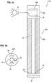
- FIG. 2a shows a schematic sectional view of an arrangement 10a according to a second embodiment.
- the assembly 10a includes a mono-endoscope 12a having a first sensor element 40, an endoscopic sheath 14 FIG. 1 from the in FIG. 2a only the optical element 32 is shown, and an output unit 70.
- the non-sterile mono-endoscope 12a is received by the sterile endoscope cover 14 and thereby shielded from the environment sterile.
- the mono-endoscope 12a has an endoscope shaft 20a projecting in the distal direction from an endoscope body 24a, at the distal tip 22a of which the first sensor element 40 is arranged.
- the endoscope shaft 20a further comprises a first observation optics 50.
- the endoscope body 24a adjoins the proximal end of the endoscope shaft 20a.
- a control unit 48 and an image sensor 46 are arranged in the endoscope body 24a.
- the electromagnetic radiation emanating from the optical element 32 in the absorption wavelength range is essentially the heat radiation of the optical element 32, which depends only on its temperature.
- This radiation is detected by the first sensor element 40 arranged at the distal tip 22a of the endoscope shaft 20a. From the spectrum of the detected radiation, the control unit 48 determines the temperature of the optical element 32. If the temperature of the optical element 32 determined by the control unit 48 exceeds a preset limit value, the control unit 48 controls the output unit 70 such that it outputs an optical and / or acoustic signal Warning signal outputs.
- the first observation optics 50 forms an optical channel that guides observation light incident on the tip 22a of the endoscope shaft 20a in an optical wavelength range from the distal end of the endoscope shaft 20a to the proximal end of the endoscope shaft 20a. After passing through the first observation optics 50, the observation light falls on the image sensor 46 and is converted by this into a signal or data.
- the signal is processed by the image display control unit 48. This makes it possible to observe an area distal to the tip 22a.
- the signal or the data can also be further processed by a further control unit outside the endoscope 12a for image display.
- FIG. 2b shows a schematic representation of the Monoendoskops 12a after FIG. 2a seen from a distal side, ie the tip 22a of the mono-endoscope 12a.
- the distal end 51 of the first observation optics 50 is arranged centrally of the tip 22a.
- the distal end 51 of the first observation optics 50 each have a distal end 54, 55 of a lighting optical system for illuminating the area distal to the tip 22a.
- the first sensor element 40 is shown in FIG FIG. 2b to the right of the distal end 51 of the observation optics 50.
- FIG. 3a shows a schematic sectional view of an arrangement 10b according to a third embodiment.
- the assembly 10b includes a mono-endoscope 12b having the first sensor element 40.
- the arrangement 10b further comprises a first optical waveguide 56, which is optically connected to the first sensor element 40.
- the arrangement 10b includes the endoscope cover 14 FIG. 1 from the in FIG. 2a only the optical element 32 is shown, and the output unit 70.
- the non-sterile mono-endoscope 12b is received in the sterile endoscopic sleeve 14 and sterilized by this sterile environment.
- the arrangement 10b according to the third embodiment according to FIG. 3a differs from the arrangement 10a according to the second embodiment according to FIG. 2a essentially by a first optical waveguide 56.
- the endoscope shaft 20b of the mono-endoscope 12b comprises the first observation optics 50 and the first optical waveguide 56.
- the mono-endoscope 12b further has an endoscope body 24b arranged at the proximal end of the endoscope shaft 20b, in which the first sensor element 40, the control unit 48 and the image sensor 46 are arranged are.
- the electromagnetic radiation in the absorption wavelength range emanating from the optical element 32 falls into the distal end 57 of the first optical waveguide 56 arranged at the distal tip 22b of the endoscope shaft 20a.
- the first optical waveguide 56 guides the electromagnetic radiation in the absorption wavelength range from its distal end 57 up to the first sensor element 40, which detects this radiation.
- the control unit 48 determines the temperature of the optical element 32 from the spectrum of the detected radiation.
- control unit 48 controls the output unit 70 such that it outputs an optical and / or audible warning signal.
- FIG. 3b shows a schematic representation of the Monoendoskops 12b after FIG. 3a seen from a distal side.
- FIG. 3a in particular shows the tip 22b of the mono-endoscope 12b.
- the distal end 57 of the first optical waveguide 56 is arranged to the right of the distal end 51 of the observation optics 50.
- FIG. 4a shows a schematic sectional view of an arrangement 10c according to a fourth embodiment.
- the arrangement comprises a mono-endoscope 12c, which has the first sensor element 40 and a beam splitter 62, an endoscope cover 14 according to FIG FIG. 1 from the in FIG. 3a only the optical element 32 is shown, as well as the output unit 70.
- the non-sterile mono-endoscope 12c is received by the sterile endoscope cover 14 and screened by this sterile against the environment.
- the arrangement 10c according to the fourth embodiment according to FIG. 3a differs from the arrangement 10a according to the second embodiment according to FIG. 2a essentially by the provision of a beam splitter 62.
- the endoscope shaft 20c contains the first observation optics 50.
- the mono-endoscope 12c further has an endoscope body 24c arranged at the proximal end of the endoscope shaft 20c, in which, in particular, the first sensor element 40, the control unit 48 and the beam splitter 62 are arranged.
- the electromagnetic radiation in the absorption wavelength range emitted from the optical element 32 is incident on the distal tip 22c of the
- the first observation optics 50 directs the electromagnetic radiation in the absorption wavelength range from its distal end 51 to the beam splitter 62.
- the beam splitter 62 directs the electromagnetic radiation in the absorption wavelength range to the first sensor element 40 that detects it Radiation detected.
- the control unit 48 determines the temperature of the optical element 32. If the temperature of the optical element 32 determined by the control unit 48 exceeds a preset limit value, the control unit 48 controls the output unit 70 such that it outputs an optical and / or acoustic signal Warning signal outputs.
- FIG. 4b shows a schematic representation of the mono endoscope 12c after FIG. 4a seen from a distal side.
- the distal end 51 of the first observation optics 50 is arranged centrally. 2
- a distal end 54, 55 of an illumination optical system for illuminating the area distal to the tip 22c are shown above and below the distal end 51 of the first observation optics 50.
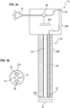
- FIG. 5a shows a schematic sectional view of an arrangement 10d according to a fifth embodiment.
- the assembly 10d includes a stereoscopic endoscope 12d having the first sensor element 40 and the first optical fiber 56.
- the assembly 10d further includes the endoscope cover 14 FIG. 1 from the in FIG. 5a only the optical element 32 is shown and the output unit 70.
- the non-sterile endoscope 12d is received in the sterile endoscopic sleeve 14 and screened by the latter in a sterile environment.
- the endoscope shaft 20d comprises the first observation optics 50, a second observation optics 52 and the first optical waveguide 56.
- the endoscope 12d further has an endoscope body 24d arranged at the proximal end of the endoscope shaft 20b, in which in particular the first sensor element 40 and the control unit 48 are arranged.
- the electromagnetic radiation in the absorption wavelength range emanating from the optical element 32 falls into the distal end 57 of the first optical waveguide 56 arranged at a distal tip 22d of the endoscope shaft 20d.
- the first optical waveguide 56 guides the electromagnetic radiation in the absorption wavelength range from its distal end 57 up to the first sensor element 40, which detects this radiation.
- the control unit 48 determines the temperature of the optical element 32. If the temperature of the optical element 32 determined by the control unit 48 exceeds a preset limit value, the control unit 48 controls the output unit 70 such that it outputs an optical and / or acoustic signal Warning signal outputs.
- the first observation optics 50 and the second observation optics 52 each form an optical channel that guides observation light incident on the tip 22d of the endoscope shaft 20d in an optical wavelength range from the distal end of the endoscope shaft 20d to the proximal end of the endoscope shaft 20d. This allows stereoscopic observation of a region distal to the tip 22d.
- FIG. 5b shows a schematic sectional view of the stereoscopic endoscope 12d after FIG. 5a seen from a distal side
- the distal end 57 of the first optical waveguide 56 is arranged centrally of the tip 22d of the endoscope 12d.
- the distal end 57 of the first optical waveguide 56 each have a distal end 54, 55 of the illumination optics for illuminating the area distal of the tip 22 d arranged.
- a distal end 51 of the first observation optics 50 is arranged.
- Right of the distal end 57 of the first Optical waveguide 56 is a distal end 53 of the second observation optics 53 arranged.
- FIG. 6a shows a schematic sectional view of an arrangement 10e according to a sixth embodiment.
- the assembly 10e includes a stereoscopic endoscope 12e having the first sensor element 40, a second sensor element 42, the first optical fiber 56, and a second optical fiber 58.
- the assembly 10e further includes the endoscope cover 14 FIG. 1 from the in FIG. 6a only the optical element 32 is shown and the output unit 70.
- the non-sterile endoscope 12e is accommodated in the sterile endoscopic sleeve 14 and shielded by the latter from the environment in a sterile manner.
- the arrangement 10e according to the sixth embodiment according to FIG. 6a differs from the arrangement 10d according to the fourth embodiment according to FIG. 4a essentially by providing a second optical waveguide 58 and a second sensor element 42.
- the endoscope shaft 20e of the endoscope 12e comprises the first observation optics 50, the second observation optics 52, the first optical waveguide 56, which is optically connected to the first sensor element.
- the endoscope shaft 20e further comprises the second optical waveguide 58, which is optically connected to the second sensor element 42 and which is optically closed at its distal end 59.
- the endoscope 12e further has an endoscope body 24e arranged at the proximal end of the endoscope shaft 20e, in which in particular the first sensor element 40, the second sensor element 42, a first image sensor 46e, a second image sensor 47e, the control unit 48, further optical elements, such as Prisms, lenses or apertures associated with the first viewing optics 50, generally indicated by the reference numeral 80, and other optical elements associated with the second viewing optics 52 and generally indicated by reference numeral 82 are disposed.
- optical elements such as Prisms, lenses or apertures associated with the first viewing optics 50, generally indicated by the reference numeral 80, and other optical elements associated with the second viewing optics 52 and generally indicated by reference numeral 82 are disposed.
- the electromagnetic radiation in the absorption wavelength range emanating from the optical element 32 falls into the distal end 57 of the first optical waveguide 56 arranged at a distal tip 22e of the endoscope shaft 20e.
- the first optical waveguide 56 guides the electromagnetic radiation in the absorption wavelength range from its distal end 57 up to the first sensor element 40, which detects this radiation.
- the control unit 48 determines the temperature of the optical element 32 from the spectrum of the detected radiation.
- the control unit 48 determines the temperature of the distal end of the endoscope 12e. Heating of the optical element 32 of the endoscopic sleeve 14 causes heating of the distal end of the endoscope 12e by heat conduction.
- the process of heat conduction takes time, it can be distinguished whether a detected heating of the optical element 32 takes place only briefly, for example by contact of the optical element 32 with a surgical instrument, such as a laser scalpel, or long term, for example by contamination the optical element 32 and a consequent absorption of illumination light.
- a surgical instrument such as a laser scalpel
- the output unit 70 outputs an audible and / or visual warning signal when the determined temperature of the optical element 32 of the endoscopic sleeve 14e and the determined temperature of the optical element of the endoscope 12e exceed a respectively preset value.
- the first observation optics 50 and the second observation optics 52 each form an optical channel which guides observation light incident on the tip 22e of the endoscope shaft 20e in the optical wavelength region from the distal end of the endoscope shaft 20e to the proximal end of the endoscope shaft 20e where it enters the other optical elements 80, 82.
- the observation light guided by the first observation optics 50 after passing through the further optical elements 80, falls onto the first image sensor 46e.
- the observation light guided by the second observation optics 52, after passing through the further optical elements 82, is incident on the second image sensor 47e.
- the first and second image sensors 46e, 47e convert the detected observation light into a signal or data, respectively.
- the signals or data are further processed by the control unit 48 for image display.
- the signals or data can also be further processed by a further control unit outside of the endoscope 12e for image display. This allows stereoscopic observation of an area distal to the tip 22e.
- FIG. 6b shows a schematic representation of the stereoscopic endoscope 12e after FIG. 6a seen from a distal side FIG. 6b the distal end 51 is shown to the left of the first observation optics 50.
- the distal end 53 of the second observation optics 53 is arranged.
- the distal end 57 of the first optical waveguide 56 is arranged to the right of the distal end 53 of the second observation optics 53.
- Above and below the distal end 51 of the first observation optics 50 and the distal end 53 of the second observation optics 52 are each a distal end 54, 55 of an illumination optics for illuminating the area distal of the tip 22 e arranged.
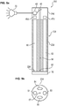
- Figure 7a shows a schematic sectional view of an arrangement 10f according to a seventh embodiment.
- the assembly 10 f comprises a stereoscopic endoscope 12 f, which the first sensor element 40, a third sensor element 44, the first optical fiber 56 and a third optical fiber 60 has.
- the assembly 10f further comprises an endoscopic sleeve, of which Figure 7a only one optical element 32f is shown as well as the output unit 70.
- the endoscope shaft 20 f of the endoscope 12 f comprises the first observation optics 50, the second observation optics 52, the first optical waveguide 56 which is optically connected to the first sensor element, and the third optical waveguide 60 which is optically connected to the third sensor element 44.
- the endoscope 12f further has an endoscope body 24f arranged at the proximal end of the endoscope shaft 20f, in which in particular the first sensor element 40, the third sensor element 44, a first image sensor 46f, a second image sensor 47f, the control unit 48, the further optical elements 80, which are associated with the first observation optics 50, and the further optical elements 82, which are associated with the second observation optics 52, are arranged.
- the electromagnetic radiation in the absorption wavelength range emanating from the optical element 32 falls into the distal end 57 of the first optical waveguide 56 located at a distal tip 22f of the endoscope shaft 20f.
- the first optical waveguide guides the electromagnetic radiation in the absorption wavelength region from its distal end 57 to the first sensor element 40, which detects this radiation.
- the control unit 48 determines the temperature of the optical element 32 from the spectrum of the detected radiation.
- control unit 48 controls the output unit 70 to output an optical and acoustic warning signal.
- a distal end 61 of the third optical waveguide 60 is disposed opposite the region 74 of the optical element 32 that is transparent to electromagnetic radiation in the absorption wavelength region.
- the third optical waveguide 60 passes the radiation incident into its distal end 61 to the third sensor element 44.
- the control unit 48 determines a temperature from the spectrum detected by the third sensor element 44.
- the electromagnetic radiation in the absorption wavelength range which is emitted, for example, from sources in the situs, can pass unobstructed through the optical element 32 in the region 74. Since the temperature of the source in the situs is determined from the spectrum of this radiation, a temperature measurement can take place in the situs.
- the first observation optics 50 and the second observation optics 52 each form an optical channel that guides observation light incident on the tip 22f of the endoscope shaft 20f in an optical wavelength range from the distal end of the endoscope shaft 20f to the proximal end of the endoscope shaft 20f where it passes into the other optical elements 80, 82 occurs.
- the observation light guided by the first observation optics 50 after passing through the further optical elements 80, falls on the first image sensor 46f.
- the observation light guided by the second observation optics 52, after passing through the further optical elements 82, is incident on the second image sensor 47f.
- the first and second image sensors 46f, 47f respectively convert the detected observation light into a signal.
- the signals are processed by the image display control unit 48.
- the signals may also be provided by another control unit be further processed outside of the endoscope 12f for image display. This allows stereoscopic observation of a region distal to the tip 22f.
- FIG. 7b shows a schematic representation of the stereoscopic endoscope 12f after Figure 7a seen from a distal side.
- the distal end 51 of the first observation optics 50 is shown.
- the distal end 53 of the second observation optics 53 is shown.
- the distal end 57 of the first optical waveguide 56 is arranged to the right of the distal end 53 of the second observation optics 53.
- the distal end 61 of the third optical waveguide 60 is arranged on the left of the distal end 51 of the first observation optics 50.
- Above and below the distal end 51 of the first observation optics 50 and the distal end 53 of the second observation optics 52 are each a distal end 54, 55 of an illumination optics for illuminating the area distal of the tip 22 f arranged.
- FIG. 7c shows a schematic representation of the optical element 32f of the endoscopy after Figure 7a seen from a proximal side.
- the optical element 32f is transparent to electromagnetic radiation in the absorption wavelength region only in the region 74.
- the region 74 is disposed on the optical element 32f so as to oppose the distal end 61 of the third optical waveguide 60 when the endoscope 12f is properly received in the endoscope skin.
Landscapes
- Health & Medical Sciences (AREA)
- Life Sciences & Earth Sciences (AREA)
- Surgery (AREA)
- Physics & Mathematics (AREA)
- Optics & Photonics (AREA)
- Biomedical Technology (AREA)
- Animal Behavior & Ethology (AREA)
- Radiology & Medical Imaging (AREA)
- Nuclear Medicine, Radiotherapy & Molecular Imaging (AREA)
- Engineering & Computer Science (AREA)
- Biophysics (AREA)
- Heart & Thoracic Surgery (AREA)
- Medical Informatics (AREA)
- Molecular Biology (AREA)
- Pathology (AREA)
- General Health & Medical Sciences (AREA)
- Public Health (AREA)
- Veterinary Medicine (AREA)
- Toxicology (AREA)
- General Physics & Mathematics (AREA)
- Endoscopes (AREA)
- Instruments For Viewing The Inside Of Hollow Bodies (AREA)
Abstract
Description
- Die Erfindung betrifft eine sterile Endoskophülle für ein nichtsteriles Endoskop. Die Endoskophülle umfasst ein an einem distalen, d.h. einem Patienten zugewandten, Ende der Endoskophülle angeordnetes optisches Element. Die Erfindung betrifft ferner eine Anordnung zur sterilen Handhabung eines nicht sterilen Endoskops in einer sterilen Umgebung.
- Bekannte Anordnungen zur sterilen Handhabung eines nicht sterilen Endoskops in einer sterilen Umgebung, wie einem Operationssaal, umfassen ein nicht steriles Endoskop und eine sterile Endoskophülle, die ein an einem distalen Ende angeordnetes optisches Element hat. Bei der Endoskophülle handelt es sich typischerweise um einen sterilen Einmalartikel oder um eine Endoskophülle, die wieder sterilisiert, d.h. wiederaufbereitet, werden kann. Eine solche Endoskophülle ist beispielsweise aus dem Dokument
DE 10 2010 022 429 A1 bekannt. Die Endoskophülle hat zwei Hüllenteile, die lösbar und fluiddicht mechanisch miteinander verbindbar sind. DokumentDE 10 2010 053 814 A1 offenbart ferner ein Endoskop für medizinische Zwecke, das in ein sterilisiertes Gehäuse eingesetzt werden kann. - Aus dem Dokument
EP 0 904 725 A1 ist ein Endoskop mit einem auswechselbaren Schaft bekannt, der als steriler Einmalartikel ausgebildet ist. Nachteilig bei diesem Endoskop sind die vergleichsweise hohen Kosten, die durch das Auswechseln des Schafts bei jeder Anwendung entstehen. - Das optische Element bekannter Endoskophüllen ist für sichtbares Licht transparent. Daher erfolgt eine Beleuchtung des Situs, d.h. des eröffneten Operationsgebiets, durch Beleuchtungslicht, das aus einem distalen Ende eines in der Endoskophülle angeordneten Endoskops abgestrahlt wird. Eine Verschmutzung des optischen Elements, beispielsweise durch Residuen, führt allerdings dazu, dass das optische Element zumindest in Teilbereichen für das Beleuchtungslicht undurchlässig wird und einen Teil des Beleuchtungslichts absorbiert. Das absorbierte Beleuchtungslicht wird in Wärme umgewandelt und bewirkt eine starke Erwärmung des optischen Elements, durch die es zu erheblichen Schädigungen an Organen kommen kann. Nachteilig bei bisher bekannten Endoskophüllen ist, dass diese Erwärmung nicht festgestellt werden kann.
- Aus dem Dokument
US 2014/0200406 A1 ist ein Endoskop bekannt, bei dem das Beschlagen eines distal angeordneten optischen Elements mithilfe von Infrarotlicht verhindert wird. Das optische Element ist derart ausgebildet, dass es das Infrarotlicht absorbiert. Durch die Absorption erwärmt sich das optisch Element, wodurch ein Beschlagen verhindert und/oder bereits vorhandenes Kondenswasser verdampft wird. - Aus dem Dokument
DE 21 29 094 A1 ist eine Alarmeinrichtung zur Temperaturüberwachung von Uranbrennstäben in einem Speicherraum bekannt. Die Alarmeinrichtung hat eine Optik zum Auffangen von aus dem Speicherraum ausgehender elektromagnetischer Strahlung in Infrarotbereich und einen Infrarotdetektor mit einem vorgeschalteten Filter, der für einen infraroten Wellenlängenbereich durchlässig ist. - Ferner ist aus Dokument
EP 0 820 250 B1 ein System zur endoskopischen Diagnose bekannt, das sowohl sichtbares als auch infrarotes Licht zur Bildgebung verwendet. - Ausgehend von dem bekannten Stand der Technik ist es Aufgabe der Erfindung, eine Endoskophülle anzugeben, bei der die Temperatur eines an einem distalen Ende der Endoskophülle angeordneten optischen Elements zuverlässig ermittelt werden kann. Darüber hinaus ist eine Anordnung zur sterilen Handhabung eines nicht sterilen Endoskops in einer sterilen Umgebung anzugeben.
- Diese Aufgabe wird durch eine Endoskophülle mit den Merkmalen des Anspruchs 1 und durch eine Anordnung mit den Merkmalen des Anspruchs 4 gelöst. Vorteilhafte Weiterbildungen sind in den abhängigen Ansprüchen angegeben.
- Die erfindungsgemäße sterile Endoskophülle für ein nichtsteriles Endoskop hat ein an einem distalen Ende der Endoskophülle angeordnetes optisches Element. Das optische Element absorbiert elektromagnetische Strahlung in einem Absorptionswellenlängenbereich, der im mittleren infraroten Wellenlängenbereich liegt.
- Unter dem mittleren infraroten Wellenlängenbereich wird in diesem Dokument der Wellenlängenbereich zwischen 3 µm und 50 µm verstanden. Dieser Wellenlängenbereich entspricht dem Wellenlängenbereich von Wärmestrahlung bei auf der Erde vorhandenen Temperaturen. In diesem Dokument wird als distal eine dem Patienten zugewandte Richtung und als proximal eine dem Patienten abgewandte Richtung bezeichnet. Bei einem Bezug auf ein Element, einen Gegenstand oder eine Anordnung wird distal und proximal in Bezug auf die bestimmungsgemäße Lage des Elements, des Gegenstandes bzw. der Anordnung verwendet.
- Da das optische Element die elektromagnetische Strahlung in dem Absorptionswellenlängenbereich absorbiert, hat das optische Element einen sehr geringen Reflexionsgrad und einen sehr hohen Emissionsgrad in dem Absorptionswellenlängenbereich. Das optische Element ist gleichsam ein geschlossener Hohlraum bzw. ein schwarzer Strahler für elektromagnetische Strahlung in dem Absorptionswellenlängenbereich. Damit entspricht die von dem optischen Element ausgehende elektromagnetische Strahlung in dem Absorptionswellenlängenbereich im Wesentlichen der von dem optischen Element ausgehenden Wärmestrahlung, die lediglich von der Temperatur des optischen Elements abhängig ist. Das optische Element ist ferner für die elektromagnetische Strahlung in dem Absorptionswellenlängenbereich undurchlässig. Quellen elektromagnetischer Strahlung in dem Absorptionswellenlängenbereich, wie beispielsweise Organe oder andere chirurgische Instrumente im Situs eines Patienten, werden durch das optische Element verdeckt. Somit ist es möglich, ausschließlich die durch das optische Element selbst abgestrahlte Wärmestrahlung mithilfe eines Sensors zu detektieren. Da aus dem Spektrum dieser Strahlung die Temperatur des optischen Elements ermittelt werden kann, ist es bei der erfindungsgemäßen Endoskophülle möglich, die Temperatur des optischen Elements zuverlässig zu ermitteln.
- Es ist vorteilhaft, wenn das optische Element in wenigstens einem optischen Wellenlängenbereich außerhalb des Absorptionswellenlängenbereichs transparent ist. Vorzugsweise liegt der wenigstens eine optische Wellenlängenbereich im Bereich des sichtbaren Lichts, d.h. in einem Bereich von 380 nm bis 780 nm. Dies erlaubt es, das optische Element, beispielsweise in Verbindung mit einem Endoskop, für die Bildgebung im optischen Bereich zu verwenden, ohne dass es dabei zu Beeinträchtigungen bei der Bildgebung kommt.
- Es ist ferner vorteilhaft, wenn der Absorptionswellenlängenbereich ein Wellenlängenbereich von 9 µm bis 10 µm, bevorzugt von 8 µm bis 12 µm, besonders bevorzugt von 8 µm bis 14 µm, ist. In dem Wellenlängenbereich von 9 µm bis 10µm liegen die Maxima von Wärmestrahlungsspektren schwarzer Körper mit den Temperaturen von 17°C bis 48°C. Durch eine Messung der von dem optischen Element ausgehenden elektromagnetischen Strahlung in diesem Wellenlängenbereich ist es möglich festzustellen, wenn sich das optische Element auf eine Temperatur oberhalb der Körpertemperatur von ca. 37°C erwärmt. In dem bevorzugten Wellenlängenbereich von 8 µm bis 12µm liegen die Maxima von Wärmestrahlungsspektren schwarzer Körper mit den Temperaturen von -31°C bis 89°C. Damit ist es möglich festzustellen, wenn sich das optische Element auf eine Temperatur oberhalb der Koagulationstemperatur von Gewebe, d.h. der Temperatur, ab der Proteine gerinnen, von ca. 60°C erwärmt. Erwärmt sich das Endoskop auf eine Temperatur oberhalb der Koagulationstemperatur, kann es zu Nekrose an Gewebe insbesondere von Organen kommen, mit dem bzw. denen das optische Element in Kontakt kommt. Der besonders bevorzugte Wellenlängenbereich von 8 µm bis 14µm umfasst die Maxima von Wärmestrahlungsspektren schwarzer Körper mit den Temperaturen von -60°C bis 89°C. Die Messung eines breiten Spektrums erlaubt eine noch zuverlässigere Bestimmung der Temperatur des optischen Elementes.
- Die Erfindung betrifft ferner eine Anordnung zur sterilen Handhabung eines nicht sterilen Endoskops in einer sterilen Umgebung. Die erfindungsgemäße Anordnung umfasst eine erfindungsgemäße sterile Endoskophülle nach Anspruch 1 oder nach einer vorteilhaften Weiterbildung und ein nicht steriles Endoskop. Das Endoskop umfasst einen Endoskopschaft und ein an einem distalen Ende des Endoskopschafts angeordnetes optischen Element. Das optische Element des Endoskops ist für elektromagnetische Strahlung in dem Absorptionswellenlängenbereich transparent ist. Das Endoskop in der Endoskophülle aufgenommen und durch diese gegenüber der Umgebung steril abgeschirmt.
- Die Verwendung des nicht sterilen Endoskops in Verbindung mit der sterilen Endoskophülle ist eine kostengünstige Alternative zur Wiedersterilisierung von mehrfach benutzbaren Endoskopen oder zur Verwendung von Einmalendoskopen. Die erfindungsgemäße Endoskophülle gestattet es ferner die Temperatur des optischen Elements zuverlässig zu ermitteln.
- Es ist vorteilhaft, wenn das Endoskop ein erstes Sensorelement hat, das eine von dem optischen Element der Endoskophülle ausgehende elektromagnetische Strahlung in dem Absorptionswellenlängenbereich erfasst. Vorzugsweise ist das Sensorelement derart ausgebildet, die von dem optischen Element ausgehende elektromagnetische Strahlung in dem Absorptionswellenlängenbereich spektral aufgelöst zu erfassen. Aus der durch das erste Sensorelement erfassten elektromagnetischen Strahlung kann die Temperatur des optischen Elements ermittelt werden.
- Vorzugsweise hat die Anordnung eine Steuereinheit, die auf Grundlage der durch das erste Sensorelement erfassten elektromagnetischen Strahlung eine Temperatur des optischen Elements der Endoskophülle ermittelt. Die durch die Steuereinheit ermittelte Temperatur kann beispielsweise durch eine Ausgabeeinheit ausgegeben werden. Dadurch kann die Temperatur automatisch überwachen und das Endoskop aus dem Körper des Patienten entfernt oder die Beleuchtung ausgeschaltet werden, bevor die Temperatur des optischen Elements einen Wert erreicht, bei dem es zu einer Gefährdung des Patienten kommen kann.
- Es ist vorteilhaft, wenn die Anordnung eine Ausgabeeinheit hat, die ein akustisches und/oder optisches Warnsignal ausgibt, wenn die ermittelte Temperatur des optischen Elements der Endoskophülle einen voreingestellten Wert erreicht und/oder überschreitet. Ein Chirurg muss hierdurch die Temperatur des optischen Elements nicht selbst überwachen und kann sich auf die Durchführung des medizinischen Eingriffs am Patienten konzentrieren. Der voreingestellte Wert liegt vorzugsweise unterhalb einer Temperatur bei der es zu einer Koagulation bzw. Nekrose von Gewebe kommt. Das Endoskop kann so rechtzeitig aus dem Körper des Patienten entfernt oder das Beleuchtungslicht ausgeschaltet werden, bevor es zu einer Gefährdung des Patienten kommt.
- Weiterhin ist es vorteilhaft, wenn der Endoskopschaft einen ersten Lichtwellenleiter enthält, der mit dem ersten Sensorelement optisch verbunden ist und der in das distale Ende des Endoskopschafts einfallende elektromagnetische Strahlung in dem Absorptionswellenlängenbereich zu dem ersten Sensorelement leitet. Durch den Lichtwellenleiter ist es möglich, das erste Sensorelement in einem proximalen Teil des Endoskops, beispielsweise einem Handstück, anzuordnen. Hierdurch wird ein kompakter Aufbau des Endoskops ermöglicht.
- Alternativ weist das Endoskop einen Strahlteiler auf, der die elektromagnetische Strahlung in dem Absorptionswellenlängenbereich aus einer Beobachtungsoptik des Endoskops auskoppelt und auf das erste Sensorelement lenkt. Die in das distale Ende des Endoskopschafts einfallende elektromagnetische Strahlung in dem Absorptionswellenlängenbereich wird durch die Beobachtungsoptik anstelle des ersten Lichtwellenleiters zu dem proximalen Ende des Endoskops geleitet. Durch die Verwendung der Beobachtungsoptik entfällt die Notwendigkeit einen eigenen optischen Kanal für die elektromagnetische Strahlung in dem Absorptionswellenlängenbereich vorzusehen. Hierdurch wird der Aufbau des Endoskops kompakter und das Endoskop lässt sich kostengünstiger herstellen.
- Es ist ferner vorteilhaft, wenn das Endoskop ein zweites Sensorelement hat, das elektromagnetische Strahlung in dem Absorptionswellenlängenbereich erfasst, und der Endoskopschaft einen zweiten Lichtwellenleiter enthält, der mit dem zweiten Sensorelement optisch verbunden ist und der elektromagnetische Strahlung in dem Absorptionswellenlängenbereich von dem distalen Ende des Endoskopschafts zu dem zweiten Sensorelement leitet. Vorzugsweise ist der zweite Lichtwellenleiter an einem distalen Ende optisch verschlossen. Die einzige von dem zweiten Lichtwellenleiter geleite Strahlung ist die von dem Verschluss des zweiten Lichtwellenleiters ausgehende Wärmestrahlung. Hierdurch ist ein Referenzkanal gebildet, mit der die Temperatur des Endoskops, insbesondere des distalen Endes des Endoskops, ermittelt werden kann. Eine Erwärmung des optischen Elements der Endoskophülle verursacht durch Wärmeleitung eine Erwärmung des distalen Endes des Endoskops. Da der Prozess der Wärmeleitung Zeit benötigt, kann mithilfe des Referenzkanals unterschieden werden, ob eine festgestellte Erwärmung des optischen Elements nur kurzfristig erfolgt, beispielsweise durch einen Kontakt des optischen Elements mit einem Laserskalpell, oder langfristig erfolgt, beispielsweise durch eine Verschmutzung des optischen Elements und eine dadurch bedingte Absorption von Beleuchtungslicht.
- Es ist vorteilhaft, wenn die Steuereinheit auf Grundlage der durch das erste Sensorelement erfassten elektromagnetischen Strahlung eine Temperatur des optischen Elements der Endoskophülle ermittelt und auf Grundlage der durch das zweite Sensorelement erfassten elektromagnetischen Strahlung eine Temperatur des optischen Elements des Endoskops ermittelt. Vorzugsweise gibt eine Ausgabeeinheit ein akustisches und/oder optisches Warnsignal aus, wenn die ermittelte Temperatur des optischen Elements der Endoskophülle und die ermittelte Temperatur des optischen Elements des Endoskops einen jeweils voreingestellten Wert erreichen und/oder überschreiten. Dadurch wird verhindert, dass es zu Fehlwarnungen kommt, wenn sich das optische Element nur kurzfristig erwärmt, beispielsweise durch den Kontakt mit einem anderen chirurgischen Instrument. Die Ermittlung einer für einen Patienten kritischen Temperatur des optischen Elements wird hierdurch noch zuverlässiger.
- Alternativ ermittelt die Steuereinheit eine Differenz zwischen der ermittelten Temperatur des optischen Elements der Endoskophülle und der ermittelten Temperatur des optischen Elements des Endoskops. Vorzugsweise gibt die Ausgabeeinheit ein akustisches oder optisches Warnsignal aus, wenn die ermittelte Temperatur des optischen Elements der Endoskophülle einen voreingestellten Wert erreicht und/oder überschreitet und wenn die ermittelte Differenz zwischen der ermittelten Temperatur des optischen Elements der Endoskophülle und der ermittelten Temperatur des optischen Elements des Endoskops einen voreingestellten Wert erreicht und/oder unterschreitet.
- Weiterhin ist vorteilhaft, wenn das optische Element der Endoskophülle wenigstens einen Bereich aufweist, der für elektromagnetische Strahlung in dem Absorptionswellenlängenbereich transparent ist. Vorzugsweise hat das Endoskop ein drittes Sensorelement. Der Endoskopschaft enthält vorzugsweise einen dritten Lichtwellenleiter, der mit dem dritten Sensorelement optisch verbunden ist. Ein distales Ende des dritten Lichtwellenleiters ist dem wenigstens einen Bereich gegenüberliegend angeordnet. Der dritte Lichtwellenleiter leitet in das distale Ende des dritten Lichtwellenleiters einfallende elektromagnetische Strahlung in dem Absorptionswellenlängenbereich zu dem dritten Sensorelement. Elektromagnetische Strahlung in dem Absorptionswellenlängenbereich, die beispielsweise von Quellen im Situs emittiert wird, kann das optische Element in dem wenigstens einen Bereich ungehindert passieren und wird durch den dritten Lichtwellenleiter zu dem dritten Sensorelement geleitet und durch dieses erfasst. Da aus dem Spektrum dieser Strahlung die Temperatur der Quelle im Situs ermittelt werden kann, ist es möglich, eine Temperaturmessung im Situs, beispielsweise zu diagnostischen Zwecken, durchzuführen. Das dritte Sensorelement kann ein Bildsensor sein. Hierdurch kann die durch das dritte Sensorelement erfasste elektromagnetische Strahlung in dem Absorptionswellenlängenbereich zur Bildgebung verwendet werden.
- Bei dem Vorsehen von unterschiedlichen optischen Elementen in verschiedenen Endoskophüllen kann über die Wahl der Endoskophülle die Abbildung des mit Hilfe des Endoskops detektierten Lichts verändert werden, sodass die optischen Bildaufnahmeeigenschaften des Endoskops durch die Wahl der Hülle verändert werden können.
- Bei dem Endoskop kann es sich um ein Monoendoskop, d.h. ein Endoskop mit nur einem optischen Kanal, oder ein stereoskopisches Endoskop handeln.
- Weitere Merkmale und Vorteile der Erfindung ergeben sich aus der folgenden Beschreibung, die die Erfindung anhand von Ausführungsbeispielen im Zusammenhang mit den beigefügten Figuren näher erläutert.
- Es zeigen:
- Figur 1
- eine Anordnung zur sterilen Handhabung eines nicht sterilen Endoskops in einer sterilen Umgebung mit einer sterilen Endoskophülle gemäß einem ersten Ausführungsbeispiel;
- Figur 2a
- eine schematische Schnittdarstellung einer Anordnung mit einem Monoendoskop gemäß einem zweiten Ausführungsbeispiel;
- Figur 2b
- eine schematische Darstellung des Monoendoskops nach
Figur 2a von einer distalen Seite her gesehen; - Figur 3a
- eine schematische Schnittdarstellung einer Anordnung mit einem Monoendoskop gemäß einem dritten Ausführungsbeispiel;
- Figur 3b
- eine schematische Darstellung des Monoendoskops nach
Figur 3a von einer distalen Seite hergesehen; - Figur 4a
- eine schematische Schnittdarstellung einer Anordnung mit einem Monoendoskop gemäß einem vierten Ausführungsbeispiel;
- Figur 4b
- eine schematische Darstellung des Monoendoskops nach
Figur 4a von einer distalen Seite her gesehen; - Figur 5a
- eine schematische Schnittdarstellung einer Anordnung mit einem stereoskopischen Endoskop gemäß einem fünften Ausführungsbeispiel;
- Figur 5b
- eine schematische Darstellung des stereoskopischen Endoskops gemäß nach
Figur 5a von einer distalen Seite her gesehen; - Figur 6a
- eine schematische Schnittdarstellung einer Anordnung mit einem stereoskopischen Endoskop gemäß einem sechsten Ausführungsbeispiel;
- Figur 6b
- eine schematische Darstellung des stereoskopischen Endoskops nach
Figur 6a von einer distalen Seite her gesehen; - Figur 7a
- eine schematische Schnittdarstellung einer Anordnung mit einem stereoskopischen Endoskop gemäß einem siebenten Ausführungsbeispiel;
- Figur 7b
- eine schematische Darstellung des stereoskopischen Endoskops nach
Figur 7a von einer distalen Seite her gesehen in einer schematischen Darstellung; und - Figur 7c
- eine schematische Darstellung eines optischen Elements der Endoskophülle nach den
Figur 7a und 7b von einer proximalen Seite her gesehen; -
Figur 1 zeigt perspektivische Darstellung einer Anordnung 10 zur sterilen Handhabung eines nicht sterilen Endoskops 12 in einer sterilen Umgebung gemäß einem ersten Ausführungsbeispiel. Die Anordnung 10 umfasst neben dem Endoskop 12 eine sterile Endoskophülle 14. - Das Endoskop 12 hat einen an einem proximalen Ende eines Endoskopschafts 20 angeordneten Endoskopkörper 24. Das Endoskops 12, insbesondere der innere Aufbau des Endoskops 12, wird nachfolgend anhand der
Figuren 2a, 2b ,3a, 3b ,4a, 4b ,5a, 5b ,6a, 6b ,7a und 7b näher beschrieben. - Die Endoskophülle 14 umfasst einen vorderen Teil 30 zur Aufnahme des zumindest teilweise in einen Körper eines Patienten einführbaren Endoskopschafts 20. Der vordere Teil 30 der Endoskophülle 14 ist an einem distalen Ende mit Hilfe eines optischen Elements 32 verschlossen, das elektromagnetische Strahlung in einem Absorptionswellenlängenbereich von 8 µm bis 14 µm absorbiert und in einem optischen Wellenlängenbereich von 380 nm bis 780 nm transparent ist. Da das optische Element 32 die elektromagnetische Strahlung in dem Absorptionswellenlängenbereich absorbiert, hat es einen sehr geringen Reflexionsgrad und einen sehr hohen Emissionsgrad in dem Absorptionswellenlängenbereich. Damit entspricht die von dem optischen Element 32 ausgehende elektromagnetische Strahlung in dem Absorptionswellenlängenbereich im Wesentlichen der von dem optischen Element 32 ausgehenden Wärmestrahlung, die lediglich von der Temperatur des optischen Elements 32 abhängig ist. Aus dem Spektrum dieser Strahlung kann die Temperatur des optischen Elements 32 ermittelt werden.
- Die Endoskophülle 14 umfasst ferner ein Mittelteil 34 zur Aufnahme des Endoskopkörpers 24 und ein mit dem Mittelteil 34 verbundenes Verschlusselement 28 mit einer Sterilschleuse. Durch das Verschlusselement 36 ist eine Zuführ- und Entnahmeöffnung 38 der Endoskophülle 14 zum Einführen und Herausnehmen das Endoskops 12 in bzw. aus der Endoskophülle 14 gebildet. Mit Hilfe der Sterilschleuse wird ein Kontaktbereich 26 des Endoskops 12 mit elektrischen Kontakt und optischen Verbindungselementen steril abgeschirmt.
- Zur Aufnahme des Endoskops 12 in der Endoskophülle 14 wird das Endoskop 12 in Richtung des Pfeils P1 durch die geöffnete Zuführ- und Entnahmeöffnung 38 in die Endoskophülle 14 eingeführt. Hierzu wird der Endoskopschaft 20 zuerst in die Zuführ- und Entnahmeöffnung 38 eingeführt und nachfolgend bis in den vorderen Teil 30 der Endoskophülle 14 geschoben, so dass eine Spitze 22 des Endoskopschafts 20 dem an dem distalen Ende des vorderen Teils 30 angeordneten optischen Element 32 der Endoskophülle 14 gegenüberliegend angeordnet ist. Beim Einführen eines Endoskopkörpers 24 durch die Zuführ- und Entnahmeöffnung 38 in den Mittelteil 34 der Endoskophülle 14 wird der Endoskopkörper 24 durch innen im Mittelteil 34 der Endoskophülle 14 vorhandene Führungsstege 35a bis 35c geführt und in einer vorbestimmten Lage im Mittelteil 34 der Endoskophülle 14 gehalten.
-
Figur 2a zeigt eine schematische Schnittdarstellung einer Anordnung 10a gemäß einem zweiten Ausführungsbeispiel. Gleiche Elemente oder Elemente mit gleicher Funktion haben dieselben Bezugszeichen. Die Anordnung 10a umfasst ein Monoendoskop 12a, das ein erstes Sensorelement 40 hat, eine Endoskophülle 14 nachFigur 1 , von der inFigur 2a nur das optische Element 32 dargestellt ist, und eine Ausgabeeinheit 70. Das nicht sterile Monoendoskop 12a ist durch die sterile Endoskophülle 14 aufgenommen und dadurch gegenüber der Umgebung steril abgeschirmt. - Das Monoendoskop 12a hat einen in distaler Richtung von einem Endoskopkörper 24a abstehenden Endoskopschaft 20a, an dessen distaler Spitze 22a das erste Sensorelement 40 angeordnet ist. Der Endoskopschaft 20a umfasst ferner eine erste Beobachtungsoptik 50. Der Endoskopkörper 24a schließt sich am proximalen Ende des Endoskopschafts 20a an diesen an. In dem Endoskopkörper 24a sind insbesondere eine Steuereinheit 48 und ein Bildsensor 46 angeordnet.
- Die von dem optischen Element 32 ausgehende elektromagnetische Strahlung in dem Absorptionswellenlängenbereich ist im Wesentlichen die Wärmestrahlung des optischen Elements 32, die nur von dessen Temperatur abhängig ist. Diese Strahlung wird durch das an der distalen Spitze 22a des Endoskopschafts 20a angeordnete erste Sensorelement 40 erfasst. Aus dem Spektrum der erfassten Strahlung ermittelt die Steuereinheit 48 die Temperatur des optischen Elements 32. Übersteigt die durch die Steuereinheit 48 ermittelte Temperatur des optischen Elements 32 einen voreingestellten Grenzwert, steuert die Steuereinheit 48 die Ausgabeeinheit 70 derart, dass diese ein optisches und/oder akustisches Warnsignal ausgibt.
- Die erste Beobachtungsoptik 50 bildet einen optischen Kanal, der in die Spitze 22a des Endoskopschafts 20a einfallendes Beobachtungslicht in einem optischen Wellenlängenbereich von dem distalen Ende des Endoskopschafts 20a zu dem proximalen Ende des Endoskopschafts 20a leitet. Nach Durchtritt durch die erste Beobachtungsoptik 50 fällt das Beobachtungslicht auf den Bildsensor 46 und wird durch diesen in ein Signal bzw. Daten gewandelt. Das Signal wird bzw. die Datenwerden durch die Steuereinheit 48 zur Bildanzeige weiterverarbeitet. Hierdurch ist eine Beobachtung eines Bereichs distal der Spitze 22a möglich. Alternativ kann das Signal bzw. können die Daten auch durch eine weitere Steuereinheit außerhalb des Endoskops 12a zur Bildanzeige weiterverarbeitet werden.
-
Figur 2b zeigt eine schematische Darstellung des Monoendoskops 12a nachFigur 2a von einer distalen Seite her gesehen, d.h. die Spitze 22a des Monoendoskops 12a. Das distale Ende 51 der ersten Beobachtungsoptik 50 ist mittig der Spitze 22a angeordnet. In der Darstellung derFigur 2b sind oberhalb und unterhalb des distalen Endes 51 der ersten Beobachtungsoptik 50 je ein distales Ende 54, 55 einer Beleuchtungsoptik zum Beleuchten des Bereichs distal der Spitze 22a angeordnet. Das erste Sensorelement 40 ist in der Darstellung vonFigur 2b rechts des distalen Endes 51 der Beobachtungsoptik 50 angeordnet. -
Figur 3a zeigt eine schematische Schnittdarstellung einer Anordnung 10b gemäß einem dritten Ausführungsbeispiel. Die Anordnung 10b umfasst ein Monoendoskop 12b, das das erste Sensorelement 40 hat. Die Anordnung 10b umfasst ferner einen ersten Lichtwellenleiter 56, der mit dem ersten Sensorelement 40 optisch verbunden ist. Weiterhin umfasst die Anordnung 10b die Endoskophülle 14 nachFigur 1 , von der inFigur 2a nur das optische Element 32 gezeigt ist, und die Ausgabeeinheit 70. Das nicht sterile Monoendoskop 12b ist in der sterilen Endoskophülle 14 aufgenommen und durch diese gegenüber der Umgebung steril abgeschirmt. Die Anordnung 10b gemäß dem dritten Ausführungsbeispiel nachFigur 3a unterscheidet sich von der Anordnung 10a gemäß dem zweiten Ausführungsbeispiel nachFigur 2a im Wesentlichen durch eines ersten Lichtwellenleiters 56. - Der Endoskopschaft 20b des Monoendoskops 12b umfasst die erste Beobachtungsoptik 50 und den ersten Lichtwellenleiter 56. Das Monoendoskop 12b hat ferner einen an dem proximalen Ende des Endoskopschafts 20b angeordneten Endoskopkörper 24b, in dem insbesondere das erste Sensorelement 40, die Steuereinheit 48 und der Bildsensor 46 angeordnet sind.
- Die von dem optischen Element 32 ausgehende elektromagnetische Strahlung in dem Absorptionswellenlängenbereich fällt in das an der distalen Spitze 22b des Endoskopschafts 20a angeordnete distale Ende 57 des ersten Lichtwellenleiters 56. Der erste Lichtwellenleiter 56 leitet die elektromagnetische Strahlung in dem Absorptionswellenlängenbereich von seinem distalen Ende 57 bis zu dem ersten Sensorelement 40, das diese Strahlung erfasst. Aus dem Spektrum der erfassten Strahlung ermittelt die Steuereinheit 48 die Temperatur des optischen Elements 32.
- Übersteigt die durch die Steuereinheit 48 ermittelte Temperatur des optischen Elements 32 einen voreingestellten Grenzwert, steuert die Steuereinheit 48 die Ausgabeeinheit 70 derart, dass diese ein optisches und/oder akustisches Warnsignal ausgibt.
-
Figur 3b zeigt eine schematische Darstellung des Monoendoskops 12b nachFigur 3a von einer distalen Seite her gesehen.Figur 3a zeigt insbesondere die Spitze 22b des Monoendoskops 12b. In der Darstellung vonFigur 3b ist das distale Ende 57 des ersten Lichtwellenleiters 56 rechts des distalen Endes 51 der Beobachtungsoptik 50 angeordnet. -
Figur 4a zeigt eine schematische Schnittdarstellung einer Anordnung 10c gemäß einem vierten Ausführungsbeispiel. Die Anordnung umfasst ein Monoendoskop 12c, welches das erste Sensorelement 40 und einen Strahlteiler 62 hat, eine Endoskophülle 14 nachFigur 1 , von der inFigur 3a nur das optische Element 32 gezeigt ist, sowie die Ausgabeeinheit 70. Das nicht sterile Monoendoskop 12c ist durch die sterile Endoskophülle 14 aufgenommen und durch diese gegenüber der Umgebung steril abgeschirmt. Die Anordnung 10c gemäß dem vierten Ausführungsbeispiel nachFigur 3a unterscheidet sich von der Anordnung 10a gemäß dem zweiten Ausführungsbeispiel nachFigur 2a im Wesentlichen durch das Vorsehen eines Strahlteilers 62. - Der Endoskopschaft 20c enthält die erste Beobachtungsoptik 50. Das Monoendoskop 12c hat ferner einen an dem proximalen Ende des Endoskopschafts 20c angeordneten Endoskopkörper 24c, in dem insbesondere das erste Sensorelement 40, die Steuereinheit 48 und der Strahlteiler 62 angeordnet sind.
- Die von dem optischen Element 32 ausgehende elektromagnetische Strahlung in dem Absorptionswellenlängenbereich fällt auf den an einer distalen Spitze 22c des Endoskopschafts 20c angeordnete distale Ende 51 der ersten Beobachtungsoptik 50. Die erste Beobachtungsoptik 50 leitet die elektromagnetische Strahlung in dem Absorptionswellenlängenbereich von ihrem distalen Ende 51 bis zu Strahlteiler 62. Der Strahlteiler 62 lenkt die elektromagnetische Strahlung in dem Absorptionswellenlängenbereich auf das erste Sensorelement 40, das diese Strahlung erfasst. Aus dem Spektrum der erfassten Strahlung ermittelt die Steuereinheit 48 die Temperatur des optischen Elements 32. Übersteigt die durch die Steuereinheit 48 ermittelte Temperatur des optischen Elements 32 einen voreingestellten Grenzwert, steuert die Steuereinheit 48 die Ausgabeeinheit 70 derart, dass diese ein optisches und/oder akustisches Warnsignal ausgibt.
-
Figur 4b zeigt eine schematische Darstellung des Monoendoskop 12c nachFigur 4a von einer distalen Seite her gesehen. Das distale Ende 51 der ersten Beobachtungsoptik 50 ist mittig angeordnet. In sind oberhalb und unterhalb des distalen Endes 51 der ersten Beobachtungsoptik 50 je ein distales Ende 54, 55 einer Beleuchtungsoptik zum Beleuchten des Bereichs distal der Spitze 22c dargestellt. -
Figur 5a zeigt eine schematische Schnittdarstellung einer Anordnung 10d gemäß einem fünften Ausführungsbeispiel. Die Anordnung 10d umfasst ein stereoskopisches Endoskop 12d, das das erste Sensorelement 40 und den ersten Lichtwellenleiter 56 hat. Die Anordnung 10d umfasst ferner die Endoskophülle 14 nachFigur 1 , von der inFigur 5a nur das optische Element 32 gezeigt ist und die Ausgabeeinheit 70. Das nicht sterile Endoskop 12d ist in der sterilen Endoskophülle 14 aufgenommen und durch diese gegenüber der Umgebung steril abgeschirmt. - Der Endoskopschaft 20d umfasst die erste Beobachtungsoptik 50, eine zweite Beobachtungsoptik 52 und den ersten Lichtwellenleiter 56. Das Endoskop 12d hat ferner einen an dem proximalen Ende des Endoskopschafts 20b angeordneten Endoskopkörper 24d, in dem insbesondere das erste Sensorelement 40 und die Steuereinheit 48 angeordnet sind.
- Die von dem optischen Element 32 ausgehende elektromagnetische Strahlung in dem Absorptionswellenlängenbereich fällt in das an einer distalen Spitze 22d des Endoskopschafts 20d angeordnete distale Ende 57 des ersten Lichtwellenleiters 56. Der erste Lichtwellenleiter 56 leitet die elektromagnetische Strahlung in dem Absorptionswellenlängenbereich von seinem distalen Ende 57 bis zu dem ersten Sensorelement 40, das diese Strahlung erfasst. Aus dem Spektrum der erfassten Strahlung ermittelt die Steuereinheit 48 die Temperatur des optischen Elements 32. Übersteigt die durch die Steuereinheit 48 ermittelte Temperatur des optischen Elements 32 einen voreingestellten Grenzwert, steuert die Steuereinheit 48 die Ausgabeeinheit 70 derart, dass diese ein optisches und/oder akustisches Warnsignal ausgibt.
- Die erste Beobachtungsoptik 50 und die zweite Beobachtungsoptik 52 bilden jeweils einen optischen Kanal, der in die Spitze 22d des Endoskopschafts 20d einfallendes Beobachtungslicht in einem optischen Wellenlängenbereich von dem distalen Ende des Endoskopschafts 20d zu dem proximalen Ende des Endoskopschafts 20d leitet. Hierdurch ist eine stereoskopische Beobachtung eines Bereichs distal der Spitze 22d möglich.
-
Figur 5b zeigt eine schematische Schnittdarstellung des stereoskopischen Endoskops 12d nachFigur 5a von einer distalen Seite her gesehen Das distale Ende 57 des ersten Lichtwellenleiters 56 ist mittig der Spitze 22d des Endoskops 12d angeordnet. In der Darstellung derFigur 5b sind oberhalb und unterhalb des distalen Endes 57 des ersten Lichtwellenleiter 56 je ein distales Ende 54, 55 der Beleuchtungsoptik zum Beleuchten des Bereichs distal der Spitze 22d angeordnet. Links des distalen Endes 57 des ersten Lichtwellenleiters 56 ist ein distales Ende 51 der ersten Beobachtungsoptik 50 angeordnet. Rechts des distalen Endes 57 des ersten Lichtwellenleiters 56 ist ein distales Ende 53 der zweiten Beobachtungsoptik 53 angeordnet. -
Figur 6a zeigt eine schematische Schnittdarstellung einer Anordnung 10e gemäß einem sechsten Ausführungsbeispiel. Die Anordnung 10e umfasst ein stereoskopisches Endoskop 12e, das das erste Sensorelement 40, ein zweites Sensorelement 42, den ersten Lichtwellenleiter 56 und einen zweiten Lichtwellenleiter 58 hat. Die Anordnung 10e umfasst ferner die Endoskophülle 14 nachFigur 1 , von der inFigur 6a nur das optische Element 32 dargestellt ist und die Ausgabeeinheit 70. Das nicht sterile Endoskop 12e ist in der sterilen Endoskophülle 14 aufgenommen und durch diese gegenüber der Umgebung steril abgeschirmt. Die Anordnung 10e gemäß dem sechsten Ausführungsbeispiel nachFigur 6a unterscheidet sich von der Anordnung 10d gemäß dem vierten Ausführungsbeispiel nachFigur 4a im Wesentlichen durch Vorsehen eines zweiten Lichtwellenleiters 58 und eines zweiten Sensorelements 42. - Der Endoskopschaft 20e des Endoskops 12e umfasst die erste Beobachtungsoptik 50, die zweite Beobachtungsoptik 52, den ersten Lichtwellenleiter 56, der mit dem ersten Sensorelement optisch verbunden ist. Der Endoskopschaft 20e umfasst ferner den zweiten Lichtwellenleiter 58, der mit dem zweiten Sensorelement 42 optisch verbunden ist und der an seinem distalen Ende 59 optisch verschlossen ist. Das Endoskop 12e hat ferner einen an dem proximalen Ende des Endoskopschafts 20e angeordneten Endoskopkörper 24e, in dem insbesondere das erste Sensorelement 40, das zweite Sensorelement 42, ein erster Bildsensor 46e, ein zweiter Bildsensor 47e, die Steuereinheit 48, weitere optische Elemente, wie beispielsweise Prismen, Linsen oder Blenden, die der ersten Beobachtungsoptik 50 zugeordnet sind und die allgemein mit dem Bezugszeichen 80 versehen sind, und weitere optische Elemente, die der zweiten Beobachtungsoptik 52 zugeordnet sind und die allgemein mit dem Bezugszeichen 82 versehen sind, angeordnet sind.
- Die von dem optischen Element 32 ausgehende elektromagnetische Strahlung in dem Absorptionswellenlängenbereich fällt in das an einer distalen Spitze 22e des Endoskopschafts 20e angeordnete distale Ende 57 des ersten Lichtwellenleiters 56. Der erste Lichtwellenleiter 56 leitet die elektromagnetische Strahlung in dem Absorptionswellenlängenbereich von seinem distalen Ende 57 bis zu dem ersten Sensorelement 40, das diese Strahlung erfasst. Aus dem Spektrum der erfassten Strahlung ermittelt die Steuereinheit 48 die Temperatur des optischen Elements 32.
- Da der zweite Lichtwellenleiter 58 an seinem distalen Ende 59 optisch verschlossen ist, ist die einzige von dem zweiten Lichtwellenleiter 58 geleite Strahlung die von dem Verschluss des zweiten Lichtwellenleiters 58 selbst ausgehende Wärmestrahlung. Diese wird durch das zweite Sensorelement 42 erfasst. Aus dem Spektrum der erfassten Strahlung ermittelt die Steuereinheit 48 die Temperatur des distalen Endes des Endoskops 12e. Eine Erwärmung des optischen Elements 32 der Endoskophülle 14 verursacht durch Wärmeleitung eine Erwärmung des distalen Endes des Endoskops 12e. Da der Prozess der Wärmeleitung Zeit benötigt, kann unterschieden werden, ob eine festgestellte Erwärmung des optischen Elements 32 nur kurzfristig erfolgt, beispielsweise durch einen Kontakt des optischen Elements 32 mit einem chirurgischen Instrument, wie beispielsweise einem Laserskalpell, oder langfristig erfolgt, beispielsweise durch eine Verschmutzung des optischen Elements 32 und eine dadurch bedingte Absorption von Beleuchtungslicht.
- Die Ausgabeeinheit 70 gibt ein akustisches und/oder optisches Warnsignal aus, wenn die ermittelte Temperatur des optischen Elements 32 der Endoskophülle 14e und die ermittelte Temperatur des optischen Elements des Endoskops 12e einen jeweils voreingestellten Wert überschreiten.
- Die erste Beobachtungsoptik 50 und die zweite Beobachtungsoptik 52 bilden jeweils einen optischen Kanal, der in die Spitze 22e des Endoskopschafts 20e einfallendes Beobachtungslicht in dem optischen Wellenlängenbereich von dem distalen Ende des Endoskopschafts 20e zu dem proximalen Ende des Endoskopschafts 20e leitet, wo es in die weiteren optischen Elemente 80, 82 eintritt. Das von der ersten Beobachtungsoptik 50 geleitete Beobachtungslicht fällt nach Durchtritt durch die weiteren optischen Elemente 80 auf den ersten Bildsensor 46e. Das von der zweiten Beobachtungsoptik 52 geleitete Beobachtungslicht fällt nach Durchtritt durch die weiteren optischen Elemente 82 auf den zweiten Bildsensor 47e. Der erste und der zweite Bildsensor 46e, 47e wandeln das erfasste Beobachtungslicht jeweils in ein Signal oder in Daten. Die Signale bzw. Daten werden durch die Steuereinheit 48 zur Bildanzeige weiterverarbeitet. Hierdurch ist eine Beobachtung eines Bereichs distal der Spitze 22e möglich. Alternativ können die Signale bzw. Daten auch durch eine weitere Steuereinheit außerhalb des Endoskops 12e zur Bildanzeige weiterverarbeitet werden. Hierdurch ist eine stereoskopische Beobachtung eines Bereichs distal der Spitze 22e möglich.
-
Figur 6b zeigt eine schematische Darstellung des stereoskopischen Endoskops 12e nachFigur 6a von einer distalen Seite her gesehen InFigur 6b ist das distales Ende 51 links der ersten Beobachtungsoptik 50dargestellt. Rechts der Mitte der Spitze 22e das distales Ende 53 der zweiten Beobachtungsoptik 53 angeordnet. Das distale Ende 57 des ersten Lichtwellenleiters 56 ist rechts des distalen Endes 53 der zweiten Beobachtungsoptik 53 angeordnet. Oberhalb und unterhalb des distalen Endes 51 der ersten Beobachtungsoptik 50 und des distalen Endes 53 der zweiten Beobachtungsoptik 52 sind je ein distales Ende 54, 55 einer Beleuchtungsoptik zum Beleuchten des Bereichs distal der Spitze 22e angeordnet. -
Figur 7a zeigt eine schematische Schnittdarstellung einer Anordnung 10f gemäß einem siebenten Ausführungsbeispiel. Die Anordnung 10f umfasst ein stereoskopisches Endoskop 12f, das das erste Sensorelement 40, ein drittes Sensorelement 44, den ersten Lichtwellenleiter 56 und einen dritten Lichtwellenleiter 60 hat. Die Anordnung 10f umfasst ferner eine Endoskophülle, von der inFigur 7a nur ein optisches Element 32f dargestellt ist, sowie die die Ausgabeeinheit 70. - Von der Endoskophülle ist in
Figur 7a nur ein optisches Element 32f gezeigt, das einen Bereich 74 aufweist, der für elektromagnetische Strahlung in dem Absorptionswellenlängenbereich durchlässig ist. Der übrige Aufbau der Endoskophülle nachFigur 7a entspricht der Endoskophülle 14 nachFigur 1 . Das nicht sterile Endoskop 12f ist in der sterilen Endoskophülle aufgenommen und durch diese gegenüber der Umgebung steril abgeschirmt. - Der Endoskopschaft 20f des Endoskops 12f umfasst die erste Beobachtungsoptik 50, die zweite Beobachtungsoptik 52, den ersten Lichtwellenleiter 56 der mit dem ersten Sensorelement optisch verbunden ist, und den dritten Lichtwellenleiter 60, der mit dem dritten Sensorelement 44 optisch verbunden ist. Das Endoskop 12f hat ferner einen an dem proximalen Ende des Endoskopschafts 20f angeordneten Endoskopkörper 24f, in dem insbesondere das erste Sensorelement 40, das dritte Sensorelement 44, ein erster Bildsensor 46f, ein zweiter Bildsensor 47f, die Steuereinheit 48, die weiteren optische Elemente 80, die der ersten Beobachtungsoptik 50 zugeordnet sind, und die weiteren optische Elemente 82, die der zweiten Beobachtungsoptik 52 zugeordnet sind, angeordnet sind.
- Die von dem optischen Element 32 ausgehende elektromagnetische Strahlung in dem Absorptionswellenlängenbereich fällt in das an einer distalen Spitze 22f des Endoskopschafts 20f angeordnete distale Ende 57 des ersten Lichtwellenleiters 56. Der erste Lichtwellenleiter leitet die elektromagnetische Strahlung in dem Absorptionswellenlängenbereich von seinem distalen Ende 57 bis zu dem ersten Sensorelement 40, das diese Strahlung erfasst. Aus dem Spektrum der erfassten Strahlung ermittelt die Steuereinheit 48 die Temperatur des optischen Elements 32.
- Übersteigt die durch die Steuereinheit 48 ermittelte Temperatur des optischen Elements 32 einen voreingestellten Grenzwert, steuert die Steuereinheit 48 die Ausgabeeinheit 70 derart, dass diese ein optisches und akustisches Warnsignal ausgibt.
- Ein distales Ende 61 des dritten Lichtwellenleiters 60 ist dem Bereich 74 des optischen Elements 32, der für elektromagnetische Strahlung in dem Absorptionswellenlängenbereich transparent ist, gegenüberliegend angeordnet. Der dritte Lichtwellenleiter 60 leitet die in sein distales Ende 61 einfallende Strahlung zu dem dritten Sensorelement 44. Aus dem durch das dritte Sensorelement 44 erfassten Spektrum ermittelt die Steuereinheit 48 eine Temperatur. Die elektromagnetische Strahlung in dem Absorptionswellenlängenbereich, die beispielsweise von Quellen im Situs emittiert wird, kann das optische Element 32 in dem Bereich 74 ungehindert passieren. Da aus dem Spektrum dieser Strahlung die Temperatur der Quelle im Situs ermittelt wird, kann eine Temperaturmessung im Situs erfolgen.
- Die erste Beobachtungsoptik 50 und die zweite Beobachtungsoptik 52 bilden jeweils einen optischen Kanal, der in die Spitze 22f des Endoskopschafts 20f einfallendes Beobachtungslicht in einem optischen Wellenlängenbereich von dem distalen Ende des Endoskopschafts 20f zu dem proximalen Ende des Endoskopschafts 20f leitet, wo es in die weiteren optischen Elemente 80, 82 eintritt. Das von der ersten Beobachtungsoptik 50 geleitete Beobachtungslicht fällt nach Durchtritt durch die weiteren optischen Elemente 80 auf den ersten Bildsensor 46f. Das von der zweiten Beobachtungsoptik 52 geleitete Beobachtungslicht fällt nach Durchtritt durch die weiteren optischen Elemente 82 auf den zweiten Bildsensor 47f. Der erste und der zweite Bildsensor 46f, 47f wandeln das erfasste Beobachtungslicht jeweils in ein Signal. Die Signale werden durch die Steuereinheit 48 zur Bildanzeige weiterverarbeitet. Hierdurch ist eine Beobachtung eines Bereichs distal der Spitze 22f möglich. Alternativ können die Signale auch durch eine weitere Steuereinheit außerhalb des Endoskops 12f zur Bildanzeige weiterverarbeitet werden. Hierdurch ist eine stereoskopische Beobachtung eines Bereichs distal der Spitze 22f möglich.
-
Figur 7b zeigt eine schematische Darstellung des stereoskopischen Endoskops 12f nachFigur 7a von einer distalen Seite her gesehen. InFigur 7b ist links der Mitte der Spitze 22f ist das distales Ende 51 der ersten Beobachtungsoptik 50 dargestellt. Rechts der Mitte der Spitze 22f das distales Ende 53 der zweiten Beobachtungsoptik 53 dargestellt. Das distale Ende 57 des ersten Lichtwellenleiters 56 ist rechts des distalen Endes 53 der zweiten Beobachtungsoptik 53 angeordnet. Das distale Ende 61 des dritten Lichtwellenleiters 60 ist links des distalen Endes 51 der ersten Beobachtungsoptik 50 angeordnet. Oberhalb und unterhalb des distalen Endes 51 der ersten Beobachtungsoptik 50 und des distalen Endes 53 der zweiten Beobachtungsoptik 52 sind je ein distales Ende 54, 55 einer Beleuchtungsoptik zum Beleuchten des Bereichs distal der Spitze 22f angeordnet. -
Figur 7c zeigt eine schematische Darstellung des optischen Elements 32f der Endoskophülle nachFigur 7a von einer proximalen Seite her gesehen. Das optische Element 32f ist für elektromagnetische Strahlung in dem Absorptionswellenlängenberiech nur in dem Bereich 74 transparent. Der Bereich 74 ist derart auf dem optischen Element 32f angeordnet, dass dieser dem distalen Ende 61 des dritten Lichtwellenleiters 60 gegenüberliegt, wenn das Endoskop 12f bestimmungsgemäß in der Endoskophülle aufgenommen ist. -
- 10
- Anordnung
- 12
- Endoskop
- 14
- Endoskophülle
- 20
- Endoskopschaft
- 22
- Spitze
- 24
- Endoskopkörper
- 26
- Kontaktbereich
- 30
- Vorderer Teil
- 32
- Optisches Element
- 34
- Mittlerer Teil
- 36
- Verschlusselement
- 38
- Zuführ- und Entnahmeöffnung
- 40, 42, 44
- Sensorelement
- 46, 47
- Bildsensor
- 48
- Steuereinheit
- 50, 52
- Beobachtungsoptik
- 51, 53, 54, 55, 57, 59, 61
- Distales Ende
- 62
- Strahlteiler
- 70
- Ausgabeeinheit
- 74
- Bereich
- 80, 82
- Optische Elemente
- P1
- Richtung
Claims (15)
- Sterile Endoskophülle für ein nichtsteriles Endoskop, mit
einem an einem distalen Ende der Endoskophülle (14) angeordneten optischen Element (32)
dadurch gekennzeichnet, dass
das optische Element (32) elektromagnetische Strahlung in einem Absorptionswellenlängenbereich absorbiert, der im mittleren infraroten Wellenlängenbereich liegt. - Endoskophülle nach Anspruch 1, dadurch gekennzeichnet, dass das optische Element (32) in wenigstens einem optischen Wellenlängenbereich außerhalb des Absorptionswellenlängenbereichs transparent ist.
- Endoskophülle nach Anspruch 1 oder 2, dadurch gekennzeichnet, dass der Absorptionswellenlängenbereich ein Wellenlängenbereich von 9 µm bis 10 µm, von 8 µm bis 12 µm oder von 8 µm bis 14 µm ist.
- Anordnung zur sterilen Handhabung eines nicht sterilen Endoskops in einer sterilen Umgebung,
mit einer sterilen Endoskophülle (14), nach einem der Ansprüche 1 bis 3, und
mit einem nicht sterilen Endoskop (12), das einen Endoskopschaft (20) und
ein an einem distalen Ende des Endoskopschafts (20) angeordnetes optischen Element umfasst,
wobei das optische Element des Endoskops für elektromagnetische Strahlung in dem Absorptionswellenlängenbereich transparent ist, und
wobei das Endoskop (12) in der Endoskophülle (14) aufgenommen ist und durch diese gegenüber der Umgebung steril abgeschirmt ist. - Anordnung nach Anspruch 4, dadurch gekennzeichnet, dass das Endoskop (12) ein erstes Sensorelement (40) hat, das eine von dem optischen Element (32) der Endoskophülle (14) ausgehende elektromagnetische Strahlung in dem Absorptionswellenlängenbereich erfasst.
- Anordnung nach Anspruch 5, gekennzeichnet durch eine Steuereinheit (48), die auf Grundlage der durch das erste Sensorelement (40) erfassten elektromagnetischen Strahlung eine Temperatur des optischen Elements (32) der Endoskophülle ermittelt.
- Anordnung nach Anspruch 6, gekennzeichnet durch eine Ausgabeeinheit (70), die ein akustisches oder optisches Warnsignal ausgibt, wenn die mithilfe der Steuereinheit (48) ermittelte Temperatur des optischen Elements (32) der Endoskophülle (14) einen voreingestellten Wert erreicht und/oder überschreitet.
- Anordnung nach einem der Ansprüche 5 bis 7, dadurch gekennzeichnet, dass der Endoskopschaft (20) einen ersten Lichtwellenleiter (56) enthält, der mit dem ersten Sensorelement (40) optisch verbunden ist und der in das distale Ende des Endoskopschafts (20) einfallende elektromagnetische Strahlung in dem Absorptionswellenlängenbereich zu dem ersten Sensorelement (40) leitet.
- Anordnung nach einem der Ansprüche 5 bis 7, dadurch gekennzeichnet, dass das Endoskop (12) einen Strahlteiler (62) aufweist, der die elektromagnetische Strahlung in dem Absorptionswellenlängenbereich aus einer Beobachtungsoptik (50) des Endoskops (12) auskoppelt und auf das erste Sensorelement (40) lenkt.
- Anordnung nach Anspruch 8, dadurch gekennzeichnet, dass das Endoskop (40) ein zweites Sensorelement (42) hat, das elektromagnetische Strahlung in dem Absorptionswellenlängenbereich erfasst, und dass der Endoskopschaft (20) einen zweiten Lichtwellenleiter (58) enthält, der mit dem zweiten Sensorelement (42) optisch verbunden ist und der elektromagnetische Strahlung in dem Absorptionswellenlängenbereich von dem distalen Ende des Endoskopschafts (20) zu dem zweiten Sensorelement (42) leitet.
- Anordnung nach Anspruch 10, dadurch gekennzeichnet, dass der zweite Lichtwellenleiter (58) an einem distalen Ende (59) optisch verschlossen ist.
- Anordnung nach Anspruch 10 oder 11, gekennzeichnet durch eine oder die Steuereinheit (48), die auf Grundlage der durch das erste Sensorelement (40) erfassten elektromagnetischen Strahlung eine Temperatur des optischen Elements (32) der Endoskophülle (14) ermittelt und die auf Grundlage der durch das zweite Sensorelement (42) erfassten elektromagnetischen Strahlung eine Temperatur des optischen Elements des Endoskops (12) ermittelt.
- Anordnung nach Anspruch 12, gekennzeichnet durch eine oder die Ausgabeeinheit (70), die ein akustisches und/oder optisches Warnsignal ausgibt, wenn die ermittelte Temperatur des optischen Elements (32) der Endoskophülle (14) und die ermittelte Temperatur des optischen Elements des Endoskops (12) einen jeweils voreingestellten Wert erreichen und/oder überschreiten
- Anordnung nach einem der Ansprüche 4 bis 13, dadurch gekennzeichnet, dass das optische Element (32) der Endoskophülle (14) wenigstens einen Bereich (74) aufweist, der für elektromagnetische Strahlung in dem Absorptionswellenlängenbereich transparent ist.
- Anordnung nach Anspruch 14, dadurch gekennzeichnet, dass das Endoskop (12) ein drittes Sensorelement (44) hat und dass der Endoskopschaft (20) einen dritten Lichtwellenleiter (60) enthält, der mit dem dritten Sensorelement (44) optisch verbunden ist, wobei ein distales Ende (51) des dritten Lichtwellenleiters (60) dem wenigstens einen Bereich (74) gegenüberliegend angeordnet ist, und der in das distale Ende (61) des dritten Lichtwellenleiters (60) einfallende elektromagnetische Strahlung in dem Absorptionswellenlängenbereich zu dem dritten Sensorelement (44) leitet.
Applications Claiming Priority (1)
| Application Number | Priority Date | Filing Date | Title |
|---|---|---|---|
| DE102018110095.7A DE102018110095A1 (de) | 2018-04-26 | 2018-04-26 | Sterile Endoskophülle |
Publications (2)
| Publication Number | Publication Date |
|---|---|
| EP3560410A1 true EP3560410A1 (de) | 2019-10-30 |
| EP3560410B1 EP3560410B1 (de) | 2022-10-19 |
Family
ID=66217864
Family Applications (1)
| Application Number | Title | Priority Date | Filing Date |
|---|---|---|---|
| EP19169707.7A Active EP3560410B1 (de) | 2018-04-26 | 2019-04-17 | Anordnung zur sterilen handhabung eines nicht sterilen endoskops in einer sterilen umgebung |
Country Status (4)
| Country | Link |
|---|---|
| US (1) | US11517192B2 (de) |
| EP (1) | EP3560410B1 (de) |
| CN (1) | CN110403561A (de) |
| DE (1) | DE102018110095A1 (de) |
Families Citing this family (2)
| Publication number | Priority date | Publication date | Assignee | Title |
|---|---|---|---|---|
| EP3544482A4 (de) | 2016-11-28 | 2020-07-22 | Adaptivendo LLC | Endoskop mit abnehmbarem einwegschaft |
| USD1018844S1 (en) | 2020-01-09 | 2024-03-19 | Adaptivendo Llc | Endoscope handle |
Citations (6)
| Publication number | Priority date | Publication date | Assignee | Title |
|---|---|---|---|---|
| DE2932116A1 (de) * | 1979-08-08 | 1981-02-12 | Wolf Gmbh Richard | Endoskop zur thermografischen darstellung von infrarotbildern |
| US20050283048A1 (en) * | 2001-10-19 | 2005-12-22 | Visionscope, Llc | Portable imaging system employing a miniature endoscope |
| US20130218147A1 (en) * | 2012-02-07 | 2013-08-22 | Joe Denton Brown | Protective Sheath and Method of Using Same for Laser Surgery |
| US20150018613A1 (en) * | 2012-03-09 | 2015-01-15 | 3Shape A/S | 3d scanner with steam autoclavable tip containing a heated optical element |
| WO2015187626A1 (en) * | 2014-06-04 | 2015-12-10 | Securus Medical Group, Inc. | Temperature measurement systems, method and devices |
| DE102016007669A1 (de) * | 2016-06-24 | 2017-12-28 | Schölly Fiberoptic GmbH | Endoskopschutzhülle mit integriertem Heizelement sowie Verfahren zur Beheizung einer Endoskopschutzhülle |
Family Cites Families (9)
| Publication number | Priority date | Publication date | Assignee | Title |
|---|---|---|---|---|
| FR2093399A5 (de) | 1970-06-12 | 1972-01-28 | Commissariat Energie Atomique | |
| US5711755A (en) | 1995-04-14 | 1998-01-27 | Vipera Systems, Inc. | Endoscopic diagnostic systems and associated methods employing infrared radiation |
| WO1998035607A1 (fr) | 1997-02-13 | 1998-08-20 | Matsushita Electric Industrial Co., Ltd. | Endoscope, son procede de production et element d'insertion |
| DE102010022429B4 (de) | 2010-06-01 | 2020-10-29 | Karl Storz Se & Co. Kg | Hülle für ein Endoskop |
| DE102010053814B4 (de) | 2010-12-08 | 2018-03-22 | Markus Friedrich | Endoskop für medizinische Zwecke |
| US10582832B2 (en) * | 2013-01-17 | 2020-03-10 | Stryker Corporation | System for altering functions of at least one surgical device dependent upon information saved in an endoscope related to the endoscope |
| US10537236B2 (en) * | 2013-01-17 | 2020-01-21 | Stryker Corporation | Anti-fogging device for endoscope |
| DE102014210619A1 (de) * | 2014-06-04 | 2015-12-17 | Olympus Winter & Ibe Gmbh | Endoskop mit berührungsloser Abstandsmessung |
| DE102016106518A1 (de) * | 2016-04-08 | 2017-10-12 | Henke-Sass, Wolf Gmbh | Optiksystem für ein Endoskop |
-
2018
- 2018-04-26 DE DE102018110095.7A patent/DE102018110095A1/de active Pending
-
2019
- 2019-04-17 EP EP19169707.7A patent/EP3560410B1/de active Active
- 2019-04-25 CN CN201910337695.5A patent/CN110403561A/zh active Pending
- 2019-04-26 US US16/395,496 patent/US11517192B2/en active Active
Patent Citations (6)
| Publication number | Priority date | Publication date | Assignee | Title |
|---|---|---|---|---|
| DE2932116A1 (de) * | 1979-08-08 | 1981-02-12 | Wolf Gmbh Richard | Endoskop zur thermografischen darstellung von infrarotbildern |
| US20050283048A1 (en) * | 2001-10-19 | 2005-12-22 | Visionscope, Llc | Portable imaging system employing a miniature endoscope |
| US20130218147A1 (en) * | 2012-02-07 | 2013-08-22 | Joe Denton Brown | Protective Sheath and Method of Using Same for Laser Surgery |
| US20150018613A1 (en) * | 2012-03-09 | 2015-01-15 | 3Shape A/S | 3d scanner with steam autoclavable tip containing a heated optical element |
| WO2015187626A1 (en) * | 2014-06-04 | 2015-12-10 | Securus Medical Group, Inc. | Temperature measurement systems, method and devices |
| DE102016007669A1 (de) * | 2016-06-24 | 2017-12-28 | Schölly Fiberoptic GmbH | Endoskopschutzhülle mit integriertem Heizelement sowie Verfahren zur Beheizung einer Endoskopschutzhülle |
Also Published As
| Publication number | Publication date |
|---|---|
| US20190328220A1 (en) | 2019-10-31 |
| CN110403561A (zh) | 2019-11-05 |
| DE102018110095A1 (de) | 2019-10-31 |
| EP3560410B1 (de) | 2022-10-19 |
| US11517192B2 (en) | 2022-12-06 |
Similar Documents
| Publication | Publication Date | Title |
|---|---|---|
| US20200214739A1 (en) | Medical device having visual puncture apparatus | |
| EP0861044B1 (de) | Vorrichtung zur photodynamischen diagnose | |
| DE19542955C2 (de) | Endoskop | |
| EP1065987A1 (de) | Cas-erfassbarer endoskop-adapter | |
| EP3560409B1 (de) | Anordnung zur sterilen handhabung eines nicht-sterilen endoskops in einer sterilen umgebung | |
| CH674453A5 (de) | ||
| DE2829516C2 (de) | ||
| EP0586162A1 (de) | Blendeliminiervorrichtung | |
| DE60033796T2 (de) | Vaginalspekulum mit dichtung | |
| DE102005019143A1 (de) | Kombiniertes diagnose- und therapieunterstützendes System | |
| EP3560410B1 (de) | Anordnung zur sterilen handhabung eines nicht sterilen endoskops in einer sterilen umgebung | |
| DE202017102316U1 (de) | Medizinisches Endoskop mit Umgebungstemperatursensor sowie Laservorrichtung mit einem solchen Endoskop | |
| DE4133493A1 (de) | Diagnostisches geraet zur erkennung von krebs im fruehstadium | |
| DE102010060877B4 (de) | Trokaranordnung | |
| DE102007063419A1 (de) | Zahnbehandlungs- oder- untersuchungsvorrichtung | |
| DE102006052801A1 (de) | Ganz oder teilweise wieder verwendbare, magnetisch navigierbare Endoskopie-Kapsel und Verfahren zum Öffnen der Endoskopie-Kapsel | |
| DE202012007771U1 (de) | Meßkammer für einen optisch arbeitenden Sensor zum Bestimmen einer Konzentration eines Stoffes | |
| DE102006023108A1 (de) | Vorrichtung zur Führung und Leitung eines Instruments in einem Körper | |
| WO2013057207A1 (de) | Endoskopiesystem, steuersystem und verwendung eines steuersystems bei einem endoskopiesystem | |
| WO2001049165A1 (de) | Endoskop | |
| DE10212841B4 (de) | Medizinisches Instrument zur Behandlung von Gewebe mittels Hochfrequenzstrom sowie medizinisches System mit einem derartigen medizinischen Instrument | |
| DE60018736T2 (de) | Optisches biopsiesystem | |
| DE102007019333A1 (de) | Medizinisches Instrument zur Durchführung eines medizinischen Eingriffs | |
| DE102007055919B4 (de) | Augen-Betrachtungssystem und Verfahren hierzu | |
| DE102015102595B4 (de) | Optische Beobachtungsanordnung, Kamera, Endoskop oder Exoskop sowie Endoskop- oder Exoskopsystem |
Legal Events
| Date | Code | Title | Description |
|---|---|---|---|
| PUAI | Public reference made under article 153(3) epc to a published international application that has entered the european phase |
Free format text: ORIGINAL CODE: 0009012 |
|
| STAA | Information on the status of an ep patent application or granted ep patent |
Free format text: STATUS: THE APPLICATION HAS BEEN PUBLISHED |
|
| AK | Designated contracting states |
Kind code of ref document: A1 Designated state(s): AL AT BE BG CH CY CZ DE DK EE ES FI FR GB GR HR HU IE IS IT LI LT LU LV MC MK MT NL NO PL PT RO RS SE SI SK SM TR |
|
| AX | Request for extension of the european patent |
Extension state: BA ME |
|
| STAA | Information on the status of an ep patent application or granted ep patent |
Free format text: STATUS: REQUEST FOR EXAMINATION WAS MADE |
|
| 17P | Request for examination filed |
Effective date: 20200430 |
|
| RBV | Designated contracting states (corrected) |
Designated state(s): AL AT BE BG CH CY CZ DE DK EE ES FI FR GB GR HR HU IE IS IT LI LT LU LV MC MK MT NL NO PL PT RO RS SE SI SK SM TR |
|
| REG | Reference to a national code |
Ref country code: HK Ref legal event code: DE Ref document number: 40015760 Country of ref document: HK |
|
| GRAP | Despatch of communication of intention to grant a patent |
Free format text: ORIGINAL CODE: EPIDOSNIGR1 |
|
| STAA | Information on the status of an ep patent application or granted ep patent |
Free format text: STATUS: GRANT OF PATENT IS INTENDED |
|
| INTG | Intention to grant announced |
Effective date: 20220523 |
|
| GRAS | Grant fee paid |
Free format text: ORIGINAL CODE: EPIDOSNIGR3 |
|
| GRAA | (expected) grant |
Free format text: ORIGINAL CODE: 0009210 |
|
| STAA | Information on the status of an ep patent application or granted ep patent |
Free format text: STATUS: THE PATENT HAS BEEN GRANTED |
|
| AK | Designated contracting states |
Kind code of ref document: B1 Designated state(s): AL AT BE BG CH CY CZ DE DK EE ES FI FR GB GR HR HU IE IS IT LI LT LU LV MC MK MT NL NO PL PT RO RS SE SI SK SM TR |
|
| REG | Reference to a national code |
Ref country code: GB Ref legal event code: FG4D Free format text: NOT ENGLISH |
|
| REG | Reference to a national code |
Ref country code: CH Ref legal event code: EP |
|
| REG | Reference to a national code |
Ref country code: IE Ref legal event code: FG4D Free format text: LANGUAGE OF EP DOCUMENT: GERMAN |
|
| REG | Reference to a national code |
Ref country code: DE Ref legal event code: R096 Ref document number: 502019005947 Country of ref document: DE |
|
| REG | Reference to a national code |
Ref country code: AT Ref legal event code: REF Ref document number: 1525053 Country of ref document: AT Kind code of ref document: T Effective date: 20221115 |
|
| REG | Reference to a national code |
Ref country code: LT Ref legal event code: MG9D |
|
| REG | Reference to a national code |
Ref country code: NL Ref legal event code: MP Effective date: 20221019 |
|
| PG25 | Lapsed in a contracting state [announced via postgrant information from national office to epo] |
Ref country code: NL Free format text: LAPSE BECAUSE OF FAILURE TO SUBMIT A TRANSLATION OF THE DESCRIPTION OR TO PAY THE FEE WITHIN THE PRESCRIBED TIME-LIMIT Effective date: 20221019 |
|
| PG25 | Lapsed in a contracting state [announced via postgrant information from national office to epo] |
Ref country code: SE Free format text: LAPSE BECAUSE OF FAILURE TO SUBMIT A TRANSLATION OF THE DESCRIPTION OR TO PAY THE FEE WITHIN THE PRESCRIBED TIME-LIMIT Effective date: 20221019 Ref country code: PT Free format text: LAPSE BECAUSE OF FAILURE TO SUBMIT A TRANSLATION OF THE DESCRIPTION OR TO PAY THE FEE WITHIN THE PRESCRIBED TIME-LIMIT Effective date: 20230220 Ref country code: NO Free format text: LAPSE BECAUSE OF FAILURE TO SUBMIT A TRANSLATION OF THE DESCRIPTION OR TO PAY THE FEE WITHIN THE PRESCRIBED TIME-LIMIT Effective date: 20230119 Ref country code: LT Free format text: LAPSE BECAUSE OF FAILURE TO SUBMIT A TRANSLATION OF THE DESCRIPTION OR TO PAY THE FEE WITHIN THE PRESCRIBED TIME-LIMIT Effective date: 20221019 Ref country code: FI Free format text: LAPSE BECAUSE OF FAILURE TO SUBMIT A TRANSLATION OF THE DESCRIPTION OR TO PAY THE FEE WITHIN THE PRESCRIBED TIME-LIMIT Effective date: 20221019 Ref country code: ES Free format text: LAPSE BECAUSE OF FAILURE TO SUBMIT A TRANSLATION OF THE DESCRIPTION OR TO PAY THE FEE WITHIN THE PRESCRIBED TIME-LIMIT Effective date: 20221019 |
|
| PG25 | Lapsed in a contracting state [announced via postgrant information from national office to epo] |
Ref country code: RS Free format text: LAPSE BECAUSE OF FAILURE TO SUBMIT A TRANSLATION OF THE DESCRIPTION OR TO PAY THE FEE WITHIN THE PRESCRIBED TIME-LIMIT Effective date: 20221019 Ref country code: PL Free format text: LAPSE BECAUSE OF FAILURE TO SUBMIT A TRANSLATION OF THE DESCRIPTION OR TO PAY THE FEE WITHIN THE PRESCRIBED TIME-LIMIT Effective date: 20221019 Ref country code: LV Free format text: LAPSE BECAUSE OF FAILURE TO SUBMIT A TRANSLATION OF THE DESCRIPTION OR TO PAY THE FEE WITHIN THE PRESCRIBED TIME-LIMIT Effective date: 20221019 Ref country code: IS Free format text: LAPSE BECAUSE OF FAILURE TO SUBMIT A TRANSLATION OF THE DESCRIPTION OR TO PAY THE FEE WITHIN THE PRESCRIBED TIME-LIMIT Effective date: 20230219 Ref country code: HR Free format text: LAPSE BECAUSE OF FAILURE TO SUBMIT A TRANSLATION OF THE DESCRIPTION OR TO PAY THE FEE WITHIN THE PRESCRIBED TIME-LIMIT Effective date: 20221019 Ref country code: GR Free format text: LAPSE BECAUSE OF FAILURE TO SUBMIT A TRANSLATION OF THE DESCRIPTION OR TO PAY THE FEE WITHIN THE PRESCRIBED TIME-LIMIT Effective date: 20230120 |
|
| P01 | Opt-out of the competence of the unified patent court (upc) registered |
Effective date: 20230509 |
|
| REG | Reference to a national code |
Ref country code: DE Ref legal event code: R097 Ref document number: 502019005947 Country of ref document: DE |
|
| PG25 | Lapsed in a contracting state [announced via postgrant information from national office to epo] |
Ref country code: SM Free format text: LAPSE BECAUSE OF FAILURE TO SUBMIT A TRANSLATION OF THE DESCRIPTION OR TO PAY THE FEE WITHIN THE PRESCRIBED TIME-LIMIT Effective date: 20221019 Ref country code: RO Free format text: LAPSE BECAUSE OF FAILURE TO SUBMIT A TRANSLATION OF THE DESCRIPTION OR TO PAY THE FEE WITHIN THE PRESCRIBED TIME-LIMIT Effective date: 20221019 Ref country code: EE Free format text: LAPSE BECAUSE OF FAILURE TO SUBMIT A TRANSLATION OF THE DESCRIPTION OR TO PAY THE FEE WITHIN THE PRESCRIBED TIME-LIMIT Effective date: 20221019 Ref country code: DK Free format text: LAPSE BECAUSE OF FAILURE TO SUBMIT A TRANSLATION OF THE DESCRIPTION OR TO PAY THE FEE WITHIN THE PRESCRIBED TIME-LIMIT Effective date: 20221019 Ref country code: CZ Free format text: LAPSE BECAUSE OF FAILURE TO SUBMIT A TRANSLATION OF THE DESCRIPTION OR TO PAY THE FEE WITHIN THE PRESCRIBED TIME-LIMIT Effective date: 20221019 |
|
| PGFP | Annual fee paid to national office [announced via postgrant information from national office to epo] |
Ref country code: FR Payment date: 20230403 Year of fee payment: 5 Ref country code: DE Payment date: 20230411 Year of fee payment: 5 |
|
| PLBE | No opposition filed within time limit |
Free format text: ORIGINAL CODE: 0009261 |
|
| STAA | Information on the status of an ep patent application or granted ep patent |
Free format text: STATUS: NO OPPOSITION FILED WITHIN TIME LIMIT |
|
| PG25 | Lapsed in a contracting state [announced via postgrant information from national office to epo] |
Ref country code: SK Free format text: LAPSE BECAUSE OF FAILURE TO SUBMIT A TRANSLATION OF THE DESCRIPTION OR TO PAY THE FEE WITHIN THE PRESCRIBED TIME-LIMIT Effective date: 20221019 Ref country code: AL Free format text: LAPSE BECAUSE OF FAILURE TO SUBMIT A TRANSLATION OF THE DESCRIPTION OR TO PAY THE FEE WITHIN THE PRESCRIBED TIME-LIMIT Effective date: 20221019 |
|
| 26N | No opposition filed |
Effective date: 20230720 |
|
| PGFP | Annual fee paid to national office [announced via postgrant information from national office to epo] |
Ref country code: GB Payment date: 20230404 Year of fee payment: 5 |
|
| PG25 | Lapsed in a contracting state [announced via postgrant information from national office to epo] |
Ref country code: SI Free format text: LAPSE BECAUSE OF FAILURE TO SUBMIT A TRANSLATION OF THE DESCRIPTION OR TO PAY THE FEE WITHIN THE PRESCRIBED TIME-LIMIT Effective date: 20221019 |
|
| REG | Reference to a national code |
Ref country code: CH Ref legal event code: PL |
|
| PG25 | Lapsed in a contracting state [announced via postgrant information from national office to epo] |
Ref country code: LU Free format text: LAPSE BECAUSE OF NON-PAYMENT OF DUE FEES Effective date: 20230417 |
|
| REG | Reference to a national code |
Ref country code: BE Ref legal event code: MM Effective date: 20230430 |
|
| PG25 | Lapsed in a contracting state [announced via postgrant information from national office to epo] |
Ref country code: MC Free format text: LAPSE BECAUSE OF FAILURE TO SUBMIT A TRANSLATION OF THE DESCRIPTION OR TO PAY THE FEE WITHIN THE PRESCRIBED TIME-LIMIT Effective date: 20221019 |
|
| PG25 | Lapsed in a contracting state [announced via postgrant information from national office to epo] |
Ref country code: MC Free format text: LAPSE BECAUSE OF FAILURE TO SUBMIT A TRANSLATION OF THE DESCRIPTION OR TO PAY THE FEE WITHIN THE PRESCRIBED TIME-LIMIT Effective date: 20221019 Ref country code: LI Free format text: LAPSE BECAUSE OF NON-PAYMENT OF DUE FEES Effective date: 20230430 Ref country code: CH Free format text: LAPSE BECAUSE OF NON-PAYMENT OF DUE FEES Effective date: 20230430 |
|
| REG | Reference to a national code |
Ref country code: IE Ref legal event code: MM4A |
|
| PG25 | Lapsed in a contracting state [announced via postgrant information from national office to epo] |
Ref country code: BE Free format text: LAPSE BECAUSE OF NON-PAYMENT OF DUE FEES Effective date: 20230430 |
|
| PG25 | Lapsed in a contracting state [announced via postgrant information from national office to epo] |
Ref country code: IE Free format text: LAPSE BECAUSE OF NON-PAYMENT OF DUE FEES Effective date: 20230417 |
|
| PG25 | Lapsed in a contracting state [announced via postgrant information from national office to epo] |
Ref country code: IE Free format text: LAPSE BECAUSE OF NON-PAYMENT OF DUE FEES Effective date: 20230417 |