EP3560376B1 - Application control device, application control method, program, and recording medium - Google Patents
Application control device, application control method, program, and recording medium Download PDFInfo
- Publication number
- EP3560376B1 EP3560376B1 EP17884934.5A EP17884934A EP3560376B1 EP 3560376 B1 EP3560376 B1 EP 3560376B1 EP 17884934 A EP17884934 A EP 17884934A EP 3560376 B1 EP3560376 B1 EP 3560376B1
- Authority
- EP
- European Patent Office
- Prior art keywords
- skin
- application
- segment
- cosmetic material
- segments
- Prior art date
- Legal status (The legal status is an assumption and is not a legal conclusion. Google has not performed a legal analysis and makes no representation as to the accuracy of the status listed.)
- Active
Links
- 238000000034 method Methods 0.000 title claims description 66
- 239000000463 material Substances 0.000 claims description 110
- 239000002537 cosmetic Substances 0.000 claims description 109
- 238000004364 calculation method Methods 0.000 claims description 102
- 238000005316 response function Methods 0.000 claims description 20
- 230000003287 optical effect Effects 0.000 claims description 14
- 230000005540 biological transmission Effects 0.000 claims description 9
- 238000000149 argon plasma sintering Methods 0.000 claims 2
- 210000003491 skin Anatomy 0.000 description 188
- 238000009826 distribution Methods 0.000 description 47
- 239000000126 substance Substances 0.000 description 41
- 230000008569 process Effects 0.000 description 23
- 238000012545 processing Methods 0.000 description 16
- 230000000694 effects Effects 0.000 description 13
- 230000006870 function Effects 0.000 description 13
- XUMBMVFBXHLACL-UHFFFAOYSA-N Melanin Chemical compound O=C1C(=O)C(C2=CNC3=C(C(C(=O)C4=C32)=O)C)=C2C4=CNC2=C1C XUMBMVFBXHLACL-UHFFFAOYSA-N 0.000 description 12
- 230000000052 comparative effect Effects 0.000 description 12
- 230000033001 locomotion Effects 0.000 description 11
- 238000010521 absorption reaction Methods 0.000 description 8
- 238000001514 detection method Methods 0.000 description 7
- 238000010586 diagram Methods 0.000 description 7
- 210000002615 epidermis Anatomy 0.000 description 7
- 230000007246 mechanism Effects 0.000 description 7
- 208000003351 Melanosis Diseases 0.000 description 6
- 210000004207 dermis Anatomy 0.000 description 6
- 230000008859 change Effects 0.000 description 5
- 210000001519 tissue Anatomy 0.000 description 5
- 239000008280 blood Substances 0.000 description 4
- 210000004369 blood Anatomy 0.000 description 4
- 210000003128 head Anatomy 0.000 description 4
- 230000006872 improvement Effects 0.000 description 4
- 238000004088 simulation Methods 0.000 description 4
- 238000000342 Monte Carlo simulation Methods 0.000 description 3
- 230000001133 acceleration Effects 0.000 description 3
- 230000032683 aging Effects 0.000 description 3
- 210000001367 artery Anatomy 0.000 description 3
- 238000012937 correction Methods 0.000 description 3
- 238000009499 grossing Methods 0.000 description 3
- 239000007788 liquid Substances 0.000 description 3
- 230000000149 penetrating effect Effects 0.000 description 3
- 239000000049 pigment Substances 0.000 description 3
- 239000011148 porous material Substances 0.000 description 3
- 238000002834 transmittance Methods 0.000 description 3
- 238000012935 Averaging Methods 0.000 description 2
- CURLTUGMZLYLDI-UHFFFAOYSA-N Carbon dioxide Chemical compound O=C=O CURLTUGMZLYLDI-UHFFFAOYSA-N 0.000 description 2
- 208000032544 Cicatrix Diseases 0.000 description 2
- 210000004204 blood vessel Anatomy 0.000 description 2
- 239000003795 chemical substances by application Substances 0.000 description 2
- 239000003086 colorant Substances 0.000 description 2
- 238000004040 coloring Methods 0.000 description 2
- 230000007423 decrease Effects 0.000 description 2
- 238000005401 electroluminescence Methods 0.000 description 2
- 230000001678 irradiating effect Effects 0.000 description 2
- 231100000241 scar Toxicity 0.000 description 2
- 230000037387 scars Effects 0.000 description 2
- 230000036548 skin texture Effects 0.000 description 2
- 230000037303 wrinkles Effects 0.000 description 2
- 208000034656 Contusions Diseases 0.000 description 1
- 206010014970 Ephelides Diseases 0.000 description 1
- 238000009825 accumulation Methods 0.000 description 1
- QVGXLLKOCUKJST-UHFFFAOYSA-N atomic oxygen Chemical compound [O] QVGXLLKOCUKJST-UHFFFAOYSA-N 0.000 description 1
- 230000002457 bidirectional effect Effects 0.000 description 1
- 229910002092 carbon dioxide Inorganic materials 0.000 description 1
- 239000001569 carbon dioxide Substances 0.000 description 1
- 238000006243 chemical reaction Methods 0.000 description 1
- 235000019646 color tone Nutrition 0.000 description 1
- 230000000295 complement effect Effects 0.000 description 1
- 230000006835 compression Effects 0.000 description 1
- 238000007906 compression Methods 0.000 description 1
- 230000003247 decreasing effect Effects 0.000 description 1
- 238000005315 distribution function Methods 0.000 description 1
- 230000002708 enhancing effect Effects 0.000 description 1
- 230000001747 exhibiting effect Effects 0.000 description 1
- 238000002474 experimental method Methods 0.000 description 1
- 230000001815 facial effect Effects 0.000 description 1
- 238000010438 heat treatment Methods 0.000 description 1
- 238000003384 imaging method Methods 0.000 description 1
- 230000031700 light absorption Effects 0.000 description 1
- 239000004973 liquid crystal related substance Substances 0.000 description 1
- 210000001365 lymphatic vessel Anatomy 0.000 description 1
- 238000013507 mapping Methods 0.000 description 1
- 238000005259 measurement Methods 0.000 description 1
- 229910044991 metal oxide Inorganic materials 0.000 description 1
- 150000004706 metal oxides Chemical class 0.000 description 1
- 210000005036 nerve Anatomy 0.000 description 1
- 229910052760 oxygen Inorganic materials 0.000 description 1
- 239000001301 oxygen Substances 0.000 description 1
- 230000002093 peripheral effect Effects 0.000 description 1
- 230000010287 polarization Effects 0.000 description 1
- 239000000843 powder Substances 0.000 description 1
- 230000001012 protector Effects 0.000 description 1
- 230000009467 reduction Effects 0.000 description 1
- 230000004044 response Effects 0.000 description 1
- 239000004065 semiconductor Substances 0.000 description 1
- 230000003068 static effect Effects 0.000 description 1
- 210000004003 subcutaneous fat Anatomy 0.000 description 1
- 210000000106 sweat gland Anatomy 0.000 description 1
- 210000003462 vein Anatomy 0.000 description 1
- 230000000007 visual effect Effects 0.000 description 1
- 210000000216 zygoma Anatomy 0.000 description 1
Images


Classifications
-
- A—HUMAN NECESSITIES
- A45—HAND OR TRAVELLING ARTICLES
- A45D—HAIRDRESSING OR SHAVING EQUIPMENT; EQUIPMENT FOR COSMETICS OR COSMETIC TREATMENTS, e.g. FOR MANICURING OR PEDICURING
- A45D44/00—Other cosmetic or toiletry articles, e.g. for hairdressers' rooms
-
- A—HUMAN NECESSITIES
- A45—HAND OR TRAVELLING ARTICLES
- A45D—HAIRDRESSING OR SHAVING EQUIPMENT; EQUIPMENT FOR COSMETICS OR COSMETIC TREATMENTS, e.g. FOR MANICURING OR PEDICURING
- A45D44/00—Other cosmetic or toiletry articles, e.g. for hairdressers' rooms
- A45D44/005—Other cosmetic or toiletry articles, e.g. for hairdressers' rooms for selecting or displaying personal cosmetic colours or hairstyle
-
- B—PERFORMING OPERATIONS; TRANSPORTING
- B41—PRINTING; LINING MACHINES; TYPEWRITERS; STAMPS
- B41J—TYPEWRITERS; SELECTIVE PRINTING MECHANISMS, i.e. MECHANISMS PRINTING OTHERWISE THAN FROM A FORME; CORRECTION OF TYPOGRAPHICAL ERRORS
- B41J3/00—Typewriters or selective printing or marking mechanisms characterised by the purpose for which they are constructed
- B41J3/407—Typewriters or selective printing or marking mechanisms characterised by the purpose for which they are constructed for marking on special material
-
- B—PERFORMING OPERATIONS; TRANSPORTING
- B41—PRINTING; LINING MACHINES; TYPEWRITERS; STAMPS
- B41J—TYPEWRITERS; SELECTIVE PRINTING MECHANISMS, i.e. MECHANISMS PRINTING OTHERWISE THAN FROM A FORME; CORRECTION OF TYPOGRAPHICAL ERRORS
- B41J3/00—Typewriters or selective printing or marking mechanisms characterised by the purpose for which they are constructed
- B41J3/44—Typewriters or selective printing mechanisms having dual functions or combined with, or coupled to, apparatus performing other functions
- B41J3/445—Printers integrated in other types of apparatus, e.g. printers integrated in cameras
-
- B—PERFORMING OPERATIONS; TRANSPORTING
- B41—PRINTING; LINING MACHINES; TYPEWRITERS; STAMPS
- B41J—TYPEWRITERS; SELECTIVE PRINTING MECHANISMS, i.e. MECHANISMS PRINTING OTHERWISE THAN FROM A FORME; CORRECTION OF TYPOGRAPHICAL ERRORS
- B41J3/00—Typewriters or selective printing or marking mechanisms characterised by the purpose for which they are constructed
- B41J3/44—Typewriters or selective printing mechanisms having dual functions or combined with, or coupled to, apparatus performing other functions
- B41J3/46—Printing mechanisms combined with apparatus providing a visual indication
-
- G—PHYSICS
- G06—COMPUTING; CALCULATING OR COUNTING
- G06T—IMAGE DATA PROCESSING OR GENERATION, IN GENERAL
- G06T7/00—Image analysis
- G06T7/0002—Inspection of images, e.g. flaw detection
- G06T7/0012—Biomedical image inspection
-
- G—PHYSICS
- G06—COMPUTING; CALCULATING OR COUNTING
- G06T—IMAGE DATA PROCESSING OR GENERATION, IN GENERAL
- G06T7/00—Image analysis
- G06T7/10—Segmentation; Edge detection
- G06T7/11—Region-based segmentation
-
- G—PHYSICS
- G06—COMPUTING; CALCULATING OR COUNTING
- G06T—IMAGE DATA PROCESSING OR GENERATION, IN GENERAL
- G06T7/00—Image analysis
- G06T7/10—Segmentation; Edge detection
- G06T7/174—Segmentation; Edge detection involving the use of two or more images
-
- G—PHYSICS
- G06—COMPUTING; CALCULATING OR COUNTING
- G06T—IMAGE DATA PROCESSING OR GENERATION, IN GENERAL
- G06T7/00—Image analysis
- G06T7/40—Analysis of texture
-
- G—PHYSICS
- G06—COMPUTING; CALCULATING OR COUNTING
- G06V—IMAGE OR VIDEO RECOGNITION OR UNDERSTANDING
- G06V10/00—Arrangements for image or video recognition or understanding
- G06V10/40—Extraction of image or video features
- G06V10/50—Extraction of image or video features by performing operations within image blocks; by using histograms, e.g. histogram of oriented gradients [HoG]; by summing image-intensity values; Projection analysis
-
- G—PHYSICS
- G06—COMPUTING; CALCULATING OR COUNTING
- G06V—IMAGE OR VIDEO RECOGNITION OR UNDERSTANDING
- G06V10/00—Arrangements for image or video recognition or understanding
- G06V10/40—Extraction of image or video features
- G06V10/56—Extraction of image or video features relating to colour
-
- G—PHYSICS
- G06—COMPUTING; CALCULATING OR COUNTING
- G06V—IMAGE OR VIDEO RECOGNITION OR UNDERSTANDING
- G06V10/00—Arrangements for image or video recognition or understanding
- G06V10/40—Extraction of image or video features
- G06V10/60—Extraction of image or video features relating to illumination properties, e.g. using a reflectance or lighting model
-
- A—HUMAN NECESSITIES
- A45—HAND OR TRAVELLING ARTICLES
- A45D—HAIRDRESSING OR SHAVING EQUIPMENT; EQUIPMENT FOR COSMETICS OR COSMETIC TREATMENTS, e.g. FOR MANICURING OR PEDICURING
- A45D44/00—Other cosmetic or toiletry articles, e.g. for hairdressers' rooms
- A45D2044/007—Devices for determining the condition of hair or skin or for selecting the appropriate cosmetic or hair treatment
-
- G—PHYSICS
- G06—COMPUTING; CALCULATING OR COUNTING
- G06T—IMAGE DATA PROCESSING OR GENERATION, IN GENERAL
- G06T2207/00—Indexing scheme for image analysis or image enhancement
- G06T2207/30—Subject of image; Context of image processing
- G06T2207/30004—Biomedical image processing
- G06T2207/30088—Skin; Dermal
Definitions
- the present invention relates to an application control device, an application control method, a program, and a storage medium storing the program.
- Natural makeup is one of the attractive makeup methods to give a finish leaving a texture like a bare skin, which is supported by many women of all ages.
- the basic technique of natural makeup is to apply a thin layer of foundation. Since aging causes age spots, freckles and color unevenness, however, natural makeup becomes difficult with aging. Accordingly, a method that uses a high-concealable concealer or applies more foundation to a portion having an age spot or a freckle, or the like is used.
- a cosmetic material such as concealer or foundation is of a very difficult scheme, which is problematic because such technique is extremely difficult for general users. Because a cosmetic material such as concealer or foundation is applied on the skin directly or by using a makeup tool such as a brush or a sponge or using a finger, the boundary between an applied region and a non-applied region becomes unnatural and noticeable. Accordingly, to eliminate the unnaturalness of such a boundary, a method in which the application amount of the cosmetic material is gradually reduced across the boundary between an age spot and a bright region (a region without an age spot) is widely used.
- the concealing capability at a position to be concealed may become insufficient, and on the contrary, when many layers of the cosmetic material are applied on the age spot, an excessive amount of the cosmetic material may also be applied to the surrounding bright region of the bare skin in which the application is not necessary.
- an age spot or a freckle when a cosmetic material is applied to conceal any local difference in brightness on the skin, for example, such as a white spot at which a portion of the skin becomes whiter compared to the periphery, there is the same problem as in the case of an age spot or a freckle.
- Patent Literature 1 discloses a method in which an applying object is formed on a skin or a lip so as to have an optical property closer to the optical property of a predetermined location which is closer to the predetermined location and substantially eliminate the boundary to provide natural impression. Further, Patent Literature 1 discloses that the applying object can be formed by using an ink-jet scheme.
- PTL 1 Japanese Patent No. 5603331 .
- EP 2 335 576 A2 presents system and method for applying a reflectance modifying agent to improve the visual attractiveness of human skin.
- a computer-controlled system determines attributes of a frexel, an area of human skin, and applies a modifying agent (RMA) at the pixel level, typically to make the skin appear more youthful and so more attractive.
- the system scans the frexel, identifies unattractive attributes, and applies the RMA, typically with an inkjet printer.
- the identified attributes relate to reflectance and may refer to features such as irregular-looking light and dark spots, age-spots, scars, and bruises. Identified attributes may also relate to the surface topology of the skin, for more precisely enhancing surface irregularities such as bumps and wrinkles.
- Feature mapping may be used, for example to make cheeks appear pinker and cheekbones more prominent.
- the RMA can be applied in agreement with identified patterns, such as adding red to a red frexel, or in opposition, such as adding green or blue to a red frexel, according to idealized models of attractiveness.
- the present invention has been made in view of the problems described above and intends to provide an application control device of a cosmetic material, an application control method, a program, and a storage medium that naturally conceal a partial difference in brightness on a skin.
- An application control device according to claim 1 is provided.
- an application control device an application control method, a program, and a storage medium that naturally conceal a local difference in brightness on a skin.
- Fig. 1 is an external view illustrating the configuration in an application system 10 according to the present embodiment.
- the application system 10 has an application device 100, an image capture unit 200, and an application control device 300.
- the application device 100 is a device for applying a cosmetic material to a skin and is held by a user.
- the application device 100 has a prismatic casing, and an application head 101 is provided on one end face of the casing.
- the shape of the application device 100 is not limited thereto as long as the shape is easily held by the user and may be cylindrical or hemispherical. Further, the application device 100 may have a holding member such as a handle.
- the application head 101 is formed of an ink-jet head, for example, and has a plurality of nozzles for ejecting a cosmetic material.
- the plurality of nozzles are two-dimensionally arranged and can form an application film of a cosmetic material by ejecting the cosmetic material to a predetermined region of a skin.
- a cosmetic material tank 102 is attached to the application device 100, and the cosmetic material is supplied from the cosmetic material tank 102 to the application head 101.
- the cosmetic material tank 102 may be provided inside the application device 100.
- the cosmetic material may be liquid concealer, liquid foundation, or the like used for concealing an object that causes a local difference in brightness on a human skin including a face, for example, an age spot, a freckle, a skin pore, a white spot, various scars, or the like.
- the image capture unit 200 is provided on the side face (top face) of the casing of the application device 100 in the same orientation as the application head 101.
- the image capture unit 200 has a lens, an image pickup device, or the like and can capture an image (second image) of a skin in a narrow range on which application is performed by the application head 101.
- the image capture unit 200 is coupled to the application head 101, and the relative position of the image capture unit 200 to the application head 101 is fixed.
- the image capture unit 200 may be integrally formed with the application head 101.
- the application device 100 and the image capture unit 200 are controlled by the application control device 300.
- the application control device 300 is connected to the application device 100 and the image capture unit 200 via a wired connection component such as a Universal Serial Bus (USB) cable or via a wireless connection such as Bluetooth (registered trademark), Wi-Fi, or the like.
- the application control device 300 may be embedded in the application device 100, and when the application control device 300 is embedded in the application device 100, the application control device 300 may include the members contained in the application device 100 illustrated in Fig. 1 , for example, the application head 101 or the like.
- the application control device 300 pre-stores images (first image, image data of the skin) of a wide range of the skin including an age spot, a freckle, a skin pore, or the like that may be an application target.
- the application control device 300 can identify the position of the application head 101 on the skin by comparing the second image acquired from the image capture unit 200 with the first image.
- the application control device 300 has a display 301, and the display 301 displays various information such as an image of the skin, the status of the application head 101, or the like.
- the application control device 300 recognizes the position of the application head 101 on the skin and displays the current position of the application head 101 on the display 301.
- the user moves the application head 101 along the skin while checking the display 301, and the application head 101 automatically starts application of a cosmetic material when reaching a position at which an application target is present.
- the cosmetic material is applied based on an application amount of a cosmetic material calculated by the application control device 300 (details will be described below).
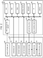
- Fig. 2 is a block diagram illustrating a configuration example in the application system 10 according to the present embodiment.
- the application device 100 has the application head 101, the cosmetic material tank 102, a motion mechanism 103, an operating unit 104, a distance sensor 105, and a motion sensor 106.
- the application control device 300 has the display 301, an image processing circuit 302, a gap control circuit 303, a head control circuit 304, a CPU 305, a RAM 306, a ROM 307, a storage device 308, a speaker 309, and an I/F 310.
- the CPU 305 may function as an acquisition unit, a division unit, or a calculation unit.
- the storage device 308 may function as a storage unit.
- the application head 101 is a piezoelectric ink-jet head, for example, and is formed of a nozzle, a pressure chamber, a piezoelectric element, a drive circuit, or the like.
- the pressure chamber is filled with a cosmetic material, and when a voltage is applied from a drive circuit to a piezoelectric element, the volume of the pressure chamber changes due to deformation of the piezoelectric element. Thereby, the cosmetic material is ejected in a form of droplets from the nozzle.
- the application head 101 may be a thermal ink-jet head that heats a cosmetic material by a heating member and ejects the cosmetic material by the pressure of generated bubbles.
- the application head 101 operates based on a control signal from the head control circuit 304.
- the cosmetic material tank 102 contains a cosmetic material and supplies the cosmetic material to the application head 101.
- the cosmetic material tank 102 may be a cartridge type container that is easy to be replaced.
- the cosmetic material is a liquid having a predetermined viscosity that enables ejection from the application head 101.
- the cosmetic material may be a substance that can conceal a local difference in brightness on the skin, for example, concealer, foundation, face powder, or the like.
- a plurality of cosmetic material tanks 102 may be provided to contain a plurality of cosmetic materials of different types or color tones.
- four cosmetic material tanks 102 are provided so as to be able to apply cosmetic materials of three colors of yellow, magenta, and cyan and a cosmetic material that can adjust illuminance, and a group of the four nozzles corresponding to the cosmetic materials can be provided on the application head 101.
- the motion mechanism 103 is formed of an actuator, a guide member, or the like and can drive the application head 101 forward and backward in the longitudinal direction of the application device 100, that is, in the direction perpendicular to a skin when the application head 101 faces the skin.
- the motion mechanism 103 performs the position control of the application head 101 in accordance with a control signal from the gap control circuit 303.
- the operating unit 104 has an operating member such as a power switch, a menu button, an application button for performing application, or the like and is used by the user to provide an instruction to the application device 100.
- the application control device 300 controls the operation of the application device 100 in accordance with the instruction of the user input from the operating unit 104.
- the application button is preferably arranged at a position at which the user can easily operate while holding the application device 100 and is arranged at a position touched by a finger of the user when the user holds the application device 100, for example. Thereby, even when the user moves the application device 100 to a portion which cannot be directly viewed (such as a cheek), the user can operate the application button by groping.
- the distance sensor 105 is an infrared sensor, an ultrasonic sensor, or the like, for example, emits a detection wave such as an infrared ray, an ultrasonic wave, or the like to an object, and receives the reflected wave.
- the distance sensor 105 can detect the distance to an object based on a time period from emission of a detection wave to reception of the reflected wave.
- a plurality of distance sensors 105 are provided in the periphery of the application head 101, and it is also possible to detect the inclination of the application head 101 relative to the skin.
- the application control device 300 maintains a constant distance between the skin and the application head 101 based on a detection signal from the distance sensor 105, and it is also possible to control the application head 101 so as not to eject the cosmetic material when the application head 101 is inclined with respect to the skin, for example.
- the motion sensor 106 includes an acceleration sensor, a gyro sensor, or a geomagnetic sensor and detects motion of the application head 101 such as movement, rotation, or the like.
- the acceleration sensor is formed of a capacitance detection element, for example, and can detect an acceleration applied to the application head 101.
- the gyro sensor is formed of a piezoelectric vibration element, for example, and has a function to detect the orientation of the application head 101.
- the geomagnetic sensor can identify the orientation of the application head 101 by detecting the geomagnetism. Based on the detection signal from the motion sensor 106, the application control device 300 can control the application head 101 so as not to eject the cosmetic material when the application head 101 is moving fast, for example.
- the image capture unit 200 has an optical system, an image pickup device, and an analog-to-digital (A/D) converter.
- the optical system has an optical filter, a fixed lens, and a focus lens and forms a subject image by focusing a light from a subject (skin) on an imaging surface of the image pickup device.
- a polarization filter can be attached to the optical system, and the specular reflection can be reduced.
- the image pickup device is a Complementary Metal Oxide Semiconductor (CMOS) image sensor or a Charge Coupled Device (CCD) image sensor, for example, and has a plurality of two dimensionally arranged pixels, color filters, and micro-lenses.
- a plurality of pixels may include pixels for image capturing or pixels for focus detection.
- the image pickup device has an electronic shutter function to control a charge accumulation time period.
- Each of the plurality of pixels outputs a pixel signal based on an incident light from the optical system.
- the A/D converter is formed of a comparison circuit, a latch circuit, or the like and converts an analog pixel signal from the image pickup device into digital RAW data.
- the image capture unit 200 can output a moving image of a predetermined frame rate in addition to a static image. Note that, while the image capture unit 200 has a function to capture an image (second image) of the skin in a narrow range on which the application is performed by the application head 101, the image capture unit 200 may also have a function to capture an image (first image) of a wide range of a skin that may be an application target.
- the display 301 is formed of a liquid crystal display or an organic Electro Luminescence (EL) display, for example.
- the display 301 performs various display such as an image from the image capture unit 200, an image stored in the storage device 308, status information on the application head 101, a menu screen, or the like based on data from the CPU 305.
- the display 301 may be a touchscreen and may also function as the operating unit 104.
- the image processing circuit 302 includes a numerical operation circuit and performs a demosaicing process on the RAW data from the image capture unit 200 to generate image data (RGB image) having each color value of red (R), green (G), or blue (B) for each pixel.
- the image processing circuit 302 also has a function of performing digital image processing such as white balance adjustment, gamma correction, edge enhancement, gradation conversion, noise reduction, compression, or the like on the image data.
- the gap control circuit 303 controls a spacing (gap) between the skin and the application head 101 by outputting a control signal to the motion mechanism 103.
- the gap control circuit 303 can control the position of the application head 101 so as to maintain a constant distance from the skin based on a detection signal from the distance sensor 105.
- the head control circuit 304 outputs control signals indicating information on a nozzle used for ejecting a cosmetic material, an application amount, or the like to the application head 101 based on an instruction from the CPU 305.
- the central processing unit (CPU) 305 has a CPU core, a cache memory, or the like and integrally controls each part of the application control device 300. Further, details will be described below, and the CPU 305 acquires image data of a skin from the storage device 308 (acquisition unit), divides the image data into a plurality of segments (division unit), and calculates the amount of a cosmetic material to be applied to the skin (calculation unit).
- the random access memory (RAM) 306 is a Dynamic RAM (DRAM), for example, and used for a work field of the CPU 305, a load field of a program, or the like.
- DRAM Dynamic RAM
- the RAM 306 temporarily stores data required for a process of the CPU 305, image data generated in the image processing circuit 302, image data read from the storage device 308, or the like.
- the read only memory (ROM) 307 is an Electrically Erasable Programmable ROM (EEPROM), for example, and stores various setting files, a basic program such as an operating system (OS), and a control program for controlling the operation of the application device 100.
- OS operating system
- the storage device (storage unit) 308 is a flash memory or a hard disk, for example, may store image data of a skin in a wide range (first image), an image of a skin in a narrow range on which application of the cosmetic material is performed (second image), other images, or the like.
- the storage device 308 may store RAW data from the image capture unit 200, image data generated in the image processing circuit 302, and the like.
- the storage device 308 can store image data captured by an external image pickup device via the I/F 310 and can also store image data on the internet via the I/F 310.
- the storage device 308 may be a portable storage medium and may be formed so as to be removable from the application control device 300 via a memory card slot, a USB connector, or the like.
- the speaker 309 has a piezoelectric vibration unit, a drive circuit, or the like and outputs a sound wave signal based on data from the CUP 305.
- the speaker 309 can play a voice message, a sound effect, or the like and is used to notify the user of the operating status of the application device 100, for example.
- the interface (I/F) 310 transmits and receives data to and from the outside such as the internet, various peripheral devices, or the like.
- the application control device 300 calculates an application amount of a cosmetic material to be applied to a skin by using image data of the skin stored in the storage device 308 (details will be described below).
- the application device 100 then applies the cosmetic material to the skin from the application head 101 based on the application amount of the cosmetic material calculated by the application control device 300.
- the application control device 300 determines the position of the second image (an image of the skin in a narrow range on which the application is performed) in the first image (an image data of a wide range of a skin). Then, the application control device 300 can control the application head 101 so as to have the application amount at a determined position in the distribution of the application amount of the cosmetic material calculated by the application control device 300.
- a determination method of the position of the second image in the first image is not particularly limited, and any method may be used.
- the present invention is not limited to such a form.
- a form in which an application amount is calculated in real time from an image captured by the image capture unit 200 and a cosmetic material is applied with the application amount may be employed.
- Fig. 3 is a schematic diagram illustrating an example of the layered structure of a human skin assumed in the calculation model, and the general structure of a facial skin is specifically illustrated. Note that, even with a skin other than a skin of a face, while each layer has a different thickness (for example, a horny layer of a sole of a foot is thicker than that of a face), the layered structure is the same as the example illustrated in Fig. 3 .
- a human skin is roughly divided into an epidermal layer 411 including a horny layer 411a, a dermis layer 412, and a hypodermis 413 from the outermost layer side to the inside and has a layered structure.
- the horny layer 411a is located outermost in the epidermal layer 411.
- a melanin pigment is produced at the bottom layer of the epidermal layer 411.
- a melanin pigment serves as a protector for the skin from ultraviolet light.
- the produced melanin pigment is deposited in the epidermal layer 411 due to various factors such as aging and forms a melanin pigmented portion 411b, and as a result, the skin appears dark and is recognized as an age spot.
- the dermis layer 412 located inside the epidermal layer 411 has blood vessels running inside.
- the blood vessel is formed of a series of an artery 414 and a vain 415.
- Arterial blood sent from the heart travels through the inside of the arteries 414 in the dermis layer 412, and after transportation of various materials such as exchange of oxygen and carbon dioxide, arterial blood changes to venous blood, flows in the veins 415 in the dermis layer 412, and returns to the heart.
- the hypodermis 413 is the innermost part of the skin, and most of the hypodermis 413 is formed of subcutaneous fat.
- a nerve, a sweat gland, a lymphatic vessel, and the like are spread inside the skin.
- the tissues of the epidermal layer 411 and the dermis layer 412 including the horny layer 411a out of the tissues forming the skin are translucent, and a visible light easily penetrates the tissues.
- a light penetrating the skin is reflected by tissues inside the skin, and a part of the light is scattered inside while being absorbed repeatedly by blood and melanin, and a part of the scattered light is again emitted out of the skin surface.
- a light is emitted to a certain point on a skin, it can be observed that the light which is again emitted out of the skin is spread concentrically around the entry point.
- a light emitted on a skin scattering inside the skin and being emitted out of a wide range including the entry point has, so to speak, the same effect as irradiating the skin surface with light from the backside.
- the contrast of brightness and darkness is the very signal indicating that there are fine unevenness parts on the surface, and a greater contrast ratio enables easier recognition of the surface.
- the mechanism is the same as the mechanism in which eyes work so as to maximize a contrast ratio when focusing on the surface.
- the former allows the presence of the surface to be clearly recognized, and the latter makes the presence of the surface unclear.
- the degree of easiness of recognizing the surface is expressed as a texture, it is considered that the former gives an impression of dullness and the latter gives an impression of depth or clearness.
- a light emitted out of a single point on a skin is considered here. It can be understood that a light emitted out of a single point of the skin is established by the sum of lights that enter the periphery of the point, scatter inside the skin, and travel around. Therefore, when a substance preventing a light from entering the skin is present at a position slightly apart from the point, there is no longer a light that is supposed to originally travel around from the position, which reduces brightness for the amount thereof.
- the high-concealable application substance is the very substance preventing the light entry and causes a greater effect at a position closer to the boundary of the application substance. This results in a phenomenon in which the vicinity of the boundary of the application substance becomes darker than the periphery. Therefore, the periphery of the application substance is surrounded by dark shadows, the applied portion is in a state of being emphasized and causes unnaturalness. For this reason, when foundation is applied to only the portion of an age spot so as not to cause unnaturalness, it is required that the application amount distribution be carefully adjusted especially at the boundary part.
- the inventors have found that it is possible to naturally conceal a partial difference in brightness on a skin by calculating an application amount of a cosmetic material by using a predetermined calculation model and applying a cosmetic material by using an application device so as to apply the calculated application amount of the cosmetic material.
- unnaturalness at the application boundary of a cosmetic material is caused by (1) a unique optical property of a skin, that is, the property of a light penetrating and scattering, and (2) calculation accuracy of an application amount and application accuracy. Therefore, according to the calculation model in which at least one of the factors described above is considered in advance, an appropriate application amount for each point is theoretically calculated.
- this can be useful reference information not only when a device is used for application but also when the user applies a cosmetic material by herself.
- An application amount of a cosmetic material to be applied to a skin having the layered structure illustrated in Fig. 3 is calculated by using a calculation model.
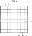
- Fig. 4 is a schematic diagram illustrating an example of the N segments on the skin surface.
- Each of the N segments is a square having the identical area.
- a first segment 1, a second segment 2, a third segment 3, ..., k-th segment k, ..., (N-2)-th segment N-2, (N-1)-th segment N-1, and N-th segment N are arranged in order.
- the reflectance R of the k-th segment k is represented by a subscript such as R(k) or R k .
- the application amount of the k-th segment k is represented as x k .
- scattering of a light from the k-th segment k to the k'-th segment k' is used as a spatial impulse response function of the skin and represented as I k (k, k').
- the spatial impulse response function represents a distribution of reflected light illuminance values obtained when the light is applied to an infinitesimal region and is referred to as a Point Spread Function (PSF). That is, when segments are considered, the spatial impulse response function is a function that, when light is evenly emitted to a certain single segment, represents how much light is emitted out of the periphery of a segment including that segment.
- PSF Point Spread Function
- r out , r in , t out , and t in are defined as described below. Note that the subscript “out” means a direction from the skin surface to the outside, and the subscript “in” means a direction from the skin surface to the inside.
- the value r out represents the reflectance based on a light emitted directly from the application substance without passing through the skin. As described below, since it is assumed that there is no reflection from the skin surface, it can be said that r out is a value when only the light reflected from the application substance is considered.
- the value r in represents the reflectance based on a light emitted from a segment when the light is emitted to the segment from the backside of the skin. As with the value r out , it can be said that r in is a value when only the light reflected from the application substance (inward of the skin) is considered.
- the value t out represents the transmittance of a segment from the inside to the outside.
- the value t in represents the transmittance of a segment from the outside to the inside.
- Equation (1) the reflectance R n of the segment n is expressed by Equation (1).
- R n r out x n + t out x n ⁇ k N t in x k I k k n + t out x n ⁇ k 2 N ⁇ k 1 N t in x k 1 I k 1 k 1 k 2 r in x k 2 I k 2 k 2 n + t out x n ⁇ k 3 N ⁇ k 2 N ⁇ k 1 N t in x k 1 I k 1 k 1 k 2 r in x k 2 I k 2 k 2 k 3 r in x k 3 I k 3 k 3 n + t out x n ⁇ k 4 N ⁇ k 3 N ⁇ k 2 N ⁇ k 1 N t in x k 1 I k 1 k 1 k 2 r
- the second line corresponds a light obtained when the light transmits from the outside to the inside of the segment n or another segment, reflects on the inner surface of any segment once, and then reaches the segment n.
- the third line corresponds to a light obtained when the light reflects twice, and the same applies to the fourth and subsequent lines.
- Equation (1) may be solved for N application amounts x.
- calculation of the application amount of a cosmetic material may be performed by using any calculation model other than the calculation model illustrated in Equation (1) and may be performed by adding a simplifying scheme to various calculation models including the calculation model illustrated in Equation (1). While an assumption for simplifying calculation is applied also in an specific example described below, the present invention is not limited thereto.
- I k (k, n) m(n)m(k)I(k, n), for simplified illustration.
- I(k, n) denotes an impulse response function representing a ratio in which a light entering the segment k is emitted out of the segment n
- the value k' is a segment number of m segments surrounding the segment k.
- the item m(n)m(k) represents energy lost in propagation inside the skin when the light enters the point k and exits the point n. Under this assumption, it is assumed that the energy lost inside the skin is determined by the entry point and the exit point.
- Equation (2) N nonlinear simultaneous equations expressed by Equation (2) are obtained.
- the reflectance R p after the cosmetic material has been applied may be set identically on the entire portion of the skin, and any reflectance R p may be set in accordance with the location on the skin.
- Equation (3) The partial differential coefficient with respect to the application amount x k at the segment n is expressed by Equation (3).
- the nonlinear simultaneous equations can be calculated by the Newton method by using a partial differential coefficient when the initial values can be set appropriately. Note that a method of setting an initial value will be described below.
- Equation (4) ⁇ k N m n m k I k n
- Equation (5) N functions are introduced as illustrated in Equation (5) in accordance with the ordinary method, and partial differential coefficients are set as illustrated in Equation (6).
- Equation (8) an application substance, an application mode, and an application amount distribution are set as illustrated in Equation (8) below.
- the application amount distribution indicates a physical quantity that defines an amount of an application substance such as a volume, a weight, a thickness, or the like of the application substance for each segment on the skin. It is assumed here that the application is performed for each fine segment set on the skin, and calculation of an application amount distribution means calculation of an application amount for each segment. Note that, since each segment has a predetermined area, an application area ratio for each segment can also be used as the application amount. Accordingly, the application substance is assumed to be applied at a predetermined area ratio in each segment. The application substance is assumed to be applied such that the thickness thereof causes the transmittance to be substantially zero. To simplify the illustration, it is assumed that the application substance has no effect to absorb light, and a light emitted on the application substance is reflected without energy loss.
- Equation (8) represents reflection and transmission of a light on the skin surface of interest that is emitted from the outside of the skin surface
- Equation (9) reflection and transmission of a light arriving from the inside of the skin surface
- Equations (12) and (13) are obtained by substituting Equations (8) to (11) into Equations (2) and (3).
- f n x ⁇ R p + x n + ⁇ k N ′ 1 ⁇ x n m n 1 ⁇ x k m k I k n + ⁇ k 2 N ′ ⁇ k 1 N ′ 1 ⁇ x n m n 1 ⁇ x k 1 m k 1 I k 1 k 2 x k 2 m k 2 m k 2 I k 2 n
- Values 1 to N' indicate a range that affects the point of interest. While the application amount is assumed to be zero outside the range (region of interest) of 1 to N, the term (1-x k ) that represents the value of traveling around of the light becomes 1 and affects the result, and thus the range from 1 to N' is used for calculation.
- Equation (14) is used as the initial value to solve Equation (12).
- Equation (12) is used as the initial value to solve Equation (12).
- x k R p ⁇ R k 1 ⁇ R k
- the initial value corresponds to an application amount when it is assumed that no light scatters inside the skin at all and is emitted only at the entry position.
- the method described above is thus referred to as a method with in-skin reflection.
- Equation (12) represents the amount of a light which reaches the surface from the inside of the skin, collides with dots of the application substance, is then reflected inside the skin, reaches the surface again, and is emitted out of the surface.
- Equation (12) is expressed as Equation (15).
- Equation (16) a simplified equation such as Equation (16) is obtained.
- the reflectance R(n) decreases by the amount of the impulse (the second term in the curly brackets) generated by dots of the application substance.
- Fig. 5 is a flowchart illustrating the operation in the application control device according to the first embodiment of the present invention. Each step of the operation of the application control device will be sequentially described below.
- the CPU 305 acquires, from the storage device 308, image data of a skin captured by an external image pickup device (not illustrated), which is a target to which a cosmetic material is applied, and loads the data to the RAM 306.
- Image data of the skin are pre-stored in the storage device 308.
- image data of the skin may be stored in the storage device 308 from an external device such as an image pickup device, a personal computer, or the like via the I/F 310 or may be stored in the storage device 308 from the internet via the I/F 310.
- a memory card as the storage device 308 in which image data of the skin is pre-stored may be attached to a memory card slot (not illustrated) provided in the application control device 300 for use.
- the CPU 305 forms the acquisition unit.
- the image data of the skin includes at least optical information and position information corresponding to each of a plurality of pixels.
- the optical information preferably includes an illuminance value and may be information in a YUV format, for example.
- the position information may be in any type as long as it includes two-dimensional position information.
- any wavelength of a visible range preferably greater than or equal to 600 nm, may be selected by using a bandpass filter or the like, any signal, preferably an R-signal, may be selected from RGB signals, or any signal, preferably an Y-signal, may be selected from YUV signals.
- the size of the acquired image data is not particularly limited as long as the image data can be divided into a plurality of segments and the application amount can be accurately calculated in an application amount calculation process (step S3) described below.
- the resolution is desirably high up to a limit at which recognition by human naked eyes is possible, may be higher than the limit, and is preferably high so as not to cause an excessively high load in image processing.
- step S2 division step
- the CPU 305 divides the acquired image data into a plurality of segments.
- the CPU 305 forms the division unit.
- the image data is divided such that one side of the segment is smaller than or equal to 200 ⁇ m, preferably larger than or equal to 20 ⁇ m and smaller than or equal to 150 ⁇ m.
- image data is divided such that one side of the segment is smaller than or equal to 200 ⁇ m, it is possible to calculate a precise application amount distribution up to a level at which determination by naked eyes is not easy, and it is possible to naturally conceal a partial difference in brightness. Further, it is possible to conceal the partial difference in brightness more naturally by setting one side smaller than or equal to 150 ⁇ m, and it is possible to reduce the processing load in the application amount calculation process described below by setting one side larger than or equal to 20 ⁇ m.
- the CPU 305 can divide the image data into N segments as illustrated in Fig. 4 .
- Each segment is a square having one side smaller than or equal to 200 ⁇ m and the same area.
- the shape of the segment may not necessarily be a square and may be a rectangle or any polygon.
- the distance between the centers of adjacent segments is preferably smaller than or equal to 200 ⁇ m, for example, larger than or equal to 20 ⁇ m and smaller than or equal to 150 ⁇ m.
- the division of image data may be performed by averaging the illuminance values of a plurality of pixels divided more finely than the pixel pitch described above.
- the CPU 305 can average the illuminance values of a plurality of pixels of 10 ⁇ m pitch and calculate segments having a desired pixel pitch.
- the CPU 305 may perform not only the image processing for dividing image data into a plurality of segment but also other image processing. In the present embodiment, it is desirable to remove noise of the image data before the division process and remove noise due to a fine foreign object, a skin pore, or the like present on the skin in advance.
- the CPU 305 then calculates an application amount of the cosmetic material to be applied to each portion of the skin corresponding to each segment from the value of each of the N divided segments.
- the CPU 305 forms the calculation unit. Further, the value of a segment used for the application amount calculation is optical information included in the segment and preferably is an illuminance value.
- a value of a single segment out of the N segments may be used to calculate an application amount of the cosmetic material to be applied to a portion of the skin corresponding to the single segment. Then, by repeating such calculation of an application amount for all of the N segments, an application amount for each portion of the skin may be calculated. Further, values of a plurality of segments out of the N segments may be used to calculate an application amount of the cosmetic material to be applied to each portion of the skin corresponding to the plurality of segments.
- the illuminance values of all of the N segments are used to calculate an application amount of the cosmetic material to be applied to each portion (N regions) of the skin corresponding to the N segments, a specific calculation of an application amount of the cosmetic material will be described below.
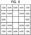
- the CPU 305 smooths application amounts of the cosmetic material obtained for each segment by performing a smoothing process.
- the smoothing process is not particularly limited and may be performed by using various spatial filters, for example, which may be a method of a process by using the Gaussian filter illustrated in Fig. 6 . By performing the smoothing process, it is possible to conceal a local difference in brightness on the skin smoothly and more naturally.
- an application amount of a cosmetic material is calculated based on a reflectance that includes and uses all wavelengths without distinction of respective wavelengths for a wide range of unspecified wavelengths (for example, the entire visible region), the application amount is slightly excessive at a wavelength having a low reflectance.
- the application amount may have slight excess or shortage on a wavelength other than the specific wavelength. Therefore, to compensate the resulted excess or shortage so as not to cause unnaturalness, it is preferable to perform coloring by the cosmetic material.
- the application amount is excessive, for example, it is preferable to appropriately compensate insufficient absorption at the position of the excessive application amount, that is, it is preferable to perform coloring.
- absorption for each wavelength can be calculated. Therefore, based on the calculated absorption for each wavelength, by applying the application substance corresponding to each wavelength (color) for each segment, it is possible to perform makeup exhibiting a good tinge, for example. It is also possible to apply three types of application substances arranging three colors of yellow, magenta, and cyan, respectively, for example, so as to exhibit a desired color by being mixed on the segment.
- FIG. 7 is a flowchart illustrating a flow of the application amount calculation according to the first embodiment of the present invention.
- the CUP 305 performs calculation of an application amount of a cosmetic material by using the calculation model of the method with in-skin reflection, that is, Equations (12) and (13) described in the calculation model described above.
- the CPU 305 sets an impulse response function for each of the N segments divided in step S2 in Fig. 5 .
- the impulse response function represents the scattering of light between each portion of the skin corresponding to each of the N segments.
- One of the N segments is used as a target segment, and segments other than the target segment are used as non-target segments.
- the impulse response function is a function representing a ratio at which a light that has entered a target portion of the skin corresponding to a target segment emitted out of the surface of the target portion of the skin, or a ratio at which a light that has entered a non-target portion of the skin corresponding to a non-target segment is emitted out of the surface of the target portion of the skin.
- the same impulse response function may be set to all of the first to the N-th segments. Further, by measuring the impulse response in each of the first to the N-th segments, impulse response functions different for respective segments (N patterns) may be set.
- the CPU 305 acquires the illuminance value from each of the first to N-th segments.
- the CPU 305 sets an absorption coefficient m(k) for each of the first to N-th segments by using Equations (5) and (6).
- the CPU 305 then calculates an application amount of the cosmetic material to be applied to each portion of the skin corresponding to each of the first to N-th segments by using the calculation model with internal reflection represented by Equations (12) and (13), and the application amount calculation process (step S3 in Fig. 5 ) ends.
- the calculation of the application amount of the cosmetic material in this step S314 is based on a light reflection scattering model described below. That is, the light reflection scattering model used in step S314 is a model in which a light obtained at a target portion of the skin corresponding to the target segment includes at least a component described in the sections (A) to (C) described below when one of the N segments is used as a target segment.
- the image data by dividing the image data into segments smaller than or equal to 200 ⁇ m, it is possible to calculate a precise application amount distribution up to a level at which determination by naked eyes is not easy, and it is possible to naturally conceal a partial difference in brightness. Further, since an application amount can be calculated more accurately by using the calculation model in which reflection inside the skin and scattering of a light inside the skin obtained by the impulse response function are considered, it is possible to conceal a local difference in brightness on the skin more naturally.
- FIG. 8 is a flowchart illustrating a flow of the application amount calculation according to the second embodiment of the present invention.
- the CUP 305 performs calculation of an application amount of a cosmetic material by using the calculation model of the method without in-skin reflection, that is, Equations (16) and (17) described in the calculation model described above.
- the second embodiment is different in only the calculation of an application amount (step S314 in Fig. 7 ). That is, skin image data acquisition (step S1 in Fig. 5 ) and division into a plurality of segments (step S2 in Fig. 5 ) are the same as those in the first embodiment. Further, in the application amount calculation process (step S3 in Fig. 5 ), the steps from the setting of an impulse response function (step S311 in Fig 7 and step S 321 in Fig. 8 ) to the setting of the absorption coefficient m(k) (step S313 in Fig. 7 and step S323 in Fig. 8 ) are the same as in the first embodiment. Therefore, only the application amount calculation (step S324 in Fig. 8 ) will be described here, and other description will be omitted.
- the CPU 305 calculates an application amount of a cosmetic material for each of the first to N-th segments by using the calculation model without internal reflection represented by Equations (16) and (17), and the application amount calculation process (step S3 in Fig. 5 ) ends.
- the calculation amount is calculated based on a light reflection scattering model from which the component described in (C) in step S314 ( Fig. 7 ) of the first embodiment is excluded (that is, the components described in (A) and (B) described above are included).
- the image data by dividing the image data into segments smaller than or equal to 200 ⁇ m, it is possible to calculate a precise application amount distribution up to a level at which determination by naked eyes is not easy, and it is possible to naturally conceal a partial difference in brightness. Further, since the application amount can be calculated more accurately by using the calculation model in which scattering of light inside the skin obtained by the impulse response function is taken into consideration, it is possible to conceal a local difference in brightness on the skin more naturally. Note that, while reflection inside the skin is not considered, the processing load in the application amount calculation process can be reduced accordingly.
- Fig. 9 is a flowchart illustrating a flow of the application amount calculation according to the third embodiment of the present invention.
- the CUP 305 performs the calculation of the application amount of the cosmetic material by using a method in which the initial solution is applied to the calculation model, that is, Equation (14) described in the calculation model described above.
- the third embodiment is different in only the calculation process of an application amount (step S3 in Fig. 5 ). That is, the acquisition of skin image data (step S1 in Fig. 5 ) and division into a plurality of segments (step S2 in Fig. 5 ) are the same as those in the first and second embodiments. Therefore, only the application amount calculation process (step S3 in Fig. 5 ) will be described here, and other description will be omitted.
- the CPU 305 acquires the illuminance value from the k-th segment out of the N segments divided in step S2 in Fig. 5 .
- the CPU 305 calculates an application amount of a cosmetic material of the k-th segment by using the calculation model described above by using the initial solution represented by Equation (14).
- the CPU 305 determines whether or not the values k and N are the same. If the determination result is NO, there is a segment for which the application amount is not calculated, and thereby the process returns to step S332. If the determination result is YES, since the application amounts have been calculated for all of the N segments, the application amount calculation process (step S3 in Fig. 5 ) ends.
- the third embodiment described above by dividing the image data into segments smaller than or equal to 200 ⁇ m, it is possible to calculate a precise application amount distribution to a level at which determination by naked eyes is not easy, and it is possible to naturally conceal a partial difference in brightness. Note that, while scattering of light inside the skin or reflection inside the skin is not considered, the processing load in the application amount calculation process can be significantly reduced accordingly.
- application of a method of calculating an application amount of a cosmetic material described above is not limited to only controlling the application of the cosmetic material by an application device employing an ink-jet or the like. According to the method of calculating an application amount of a cosmetic material described above, it is also possible to provide a makeup simulation image in which a makeup is performed with the calculated application amount or provide a makeup advice system that advises on makeup.
- a program according to an embodiment of the present invention causes a computer to execute each step of the control described in the first to third embodiments described above.
- the language of the program or the like is not particularly limited, and any well-known and commonly used language can be used.
- a storage medium is a computer readable storage medium that stores the program described above.
- the type of the storage medium or the like is not particularly limited, and any well-known and commonly used storage medium can be used.
- a multilayer film model was applied to the skin, and values of a general skin were set to parameters of the optical properties for each layer.
- the central 6.4 mm square in the skin of 12.8 mm square was used as a spot.
- the reflectance was calculated for each segment of 100 ⁇ m square in the central cross section.
- To output an average on a segment basis the average of illuminances of 16 points measured in the segment (area of 10000 ⁇ m 2 ) was used. The average was used as R(k) in the calculation below.
- Fig. 10 is a graph illustrating the simulation result of a reflectance distribution in the spot skin model and a graph illustrating the reflectance relative to the position in the central cross section of the spot skin model.
- the reflectance decreases at the central portion that is set as an age spot at which light absorption occurs.
- the boundary portion gradually changes without being formed into a right-angled shape, and it is thus considered that there is an effect of internal scattering also on the skin.
- Fig.11 is a graph illustrating the impulse response function obtained by simulating a case when the light is emitted to the spotless skin model.
- Fig. 12 is a graph illustrating the distribution of m(k) obtained by a simulation in the spot-skin model.
- the solution converged. While the initial solution (broken line) had a gradual change in the boundary because the square root of m(k) was used as the initial solution, the distribution (solid line) of m(k) obtained from Equations (5) and (6) had a sharp change and was closer to an absorption distribution that was set to have a right-angled shape in the skin model.
- Example 3 the present invention is not limited thereto.
- the error is set to smaller than or equal to 0.001, a good result can be obtained without requiring an excessive processing load.
- Fig. 13 is a graph illustrating the distribution of the application amount of the cosmetic material obtained by a simulation in the spot skin model.
- the application amount increased in both models with in-skin reflection (thick line) and without in-skin reflection (thin line).
- the increase was large. This is considered to be caused due to assumption that light was lost.
- the effect of the application substance was introduced on the surface in the skin models set in the above section (4).
- the application substance was used as having no thickness.
- the surface reflection was calculated based on the Bidirectional Reflectance Distribution Function, and the entire light entering the inside of the application substance were used as the light emitted out of the entry position as a complete scattered light.
- Each area ratio of the application substance in the segment was calculated by using the application amount distribution obtained by using the initial solution of Equation (14), the application amount distribution obtained by using Equations (12) and (13) with in-skin reflection, and the application amount distribution obtained by using Equations (16) and (17) without in-skin reflection, respectively, and the reflectance distribution after application is represented.
- Fig. 14 illustrates each calculation result.
- the bold line represents the reflectance distribution of Example 1 calculated from Equations (12) and (13) with in-skin reflection.
- the thin line represents the reflectance distribution of Example 2 calculated from Equations (16) and (17) without in-skin reflection.
- the broken line represents the reflectance distribution of Example 3 obtained by applying the initial solution (Equation (14)) to the calculation model. Further, the dashed-dotted line represents the reflectance distribution before the application of the cosmetic material. According to Fig. 14 , the following was found.
- Example 3 it was found that significant improvement was seen in a drop of the reflectance, that is, an age spot. In Example 3, since a loss caused by spread of light was not considered at all, although the correction was slightly insufficient compared to Examples 1 and 2, it was seen that a good concealing effect was obtained. Further, since the initial solution was used and no complex simultaneous equation was required to be solved, the processing load in Example 3 was extremely small.
- Example 2 it was found that significant improvement was seen in a drop of the reflectance, that is, an age spot. In Example 2, since the largest loss due to scattering of light inside the skin was estimated, although it is estimated that the portion of the age spot was corrected to a slightly higher level, it was seen that a good concealing effect was obtained.
- Example 1 it was found that significant improvement was seen in a drop of the reflectance, that is, an age spot, and the reflectance was substantially even. In Example 1, since the loss was slightly overestimated by setting the inner-face reflection to occur up to twice, although the portion of the age spot was corrected to a slightly higher level, it was seen that a significantly good concealing effect was obtained.
- the way of change in the application amount at the boundary can be regarded as substantially the same including the initial solution.
- Example 3 is a case with no loss and Example 2 is a case with an excessive loss
- a desirable application amount will appear between the results of Examples 2 and 3
- a preferable application amount distribution can also be obtained by multiplying the distribution obtained by using the initial solution by an appropriate correction factor. Therefore, the scope of the present invention can also include overpainting an application amount distribution pattern obtained by using the initial solution for multiple times.
- Fig. 15 is a graph illustrating the reflectance distribution of Comparative Example 1.
- Fig. 16 is a graph illustrating the reflectance distribution of Comparative Example 1.
Landscapes
- Engineering & Computer Science (AREA)
- Theoretical Computer Science (AREA)
- Physics & Mathematics (AREA)
- General Physics & Mathematics (AREA)
- Multimedia (AREA)
- Computer Vision & Pattern Recognition (AREA)
- Software Systems (AREA)
- Health & Medical Sciences (AREA)
- General Health & Medical Sciences (AREA)
- Medical Informatics (AREA)
- Nuclear Medicine, Radiotherapy & Molecular Imaging (AREA)
- Radiology & Medical Imaging (AREA)
- Quality & Reliability (AREA)
- Cosmetics (AREA)
- Measuring And Recording Apparatus For Diagnosis (AREA)
Applications Claiming Priority (2)
| Application Number | Priority Date | Filing Date | Title |
|---|---|---|---|
| JP2016246652 | 2016-12-20 | ||
| PCT/JP2017/045299 WO2018117020A1 (ja) | 2016-12-20 | 2017-12-18 | 塗布制御装置、塗布制御方法、プログラムおよび記録媒体 |
Publications (3)
| Publication Number | Publication Date |
|---|---|
| EP3560376A1 EP3560376A1 (en) | 2019-10-30 |
| EP3560376A4 EP3560376A4 (en) | 2020-07-15 |
| EP3560376B1 true EP3560376B1 (en) | 2021-08-18 |
Family
ID=62627698
Family Applications (1)
| Application Number | Title | Priority Date | Filing Date |
|---|---|---|---|
| EP17884934.5A Active EP3560376B1 (en) | 2016-12-20 | 2017-12-18 | Application control device, application control method, program, and recording medium |
Country Status (7)
| Country | Link |
|---|---|
| US (1) | US11501456B2 (ja) |
| EP (1) | EP3560376B1 (ja) |
| JP (1) | JP7051712B2 (ja) |
| KR (1) | KR102528866B1 (ja) |
| CN (1) | CN110177486B (ja) |
| TW (1) | TW201828861A (ja) |
| WO (1) | WO2018117020A1 (ja) |
Families Citing this family (7)
| Publication number | Priority date | Publication date | Assignee | Title |
|---|---|---|---|---|
| US20210046296A1 (en) * | 2019-08-16 | 2021-02-18 | Johnson & Johnson Consumer Inc. | Device and method for application of cosmetic compositions through a grated end effector |
| WO2021131852A1 (ja) * | 2019-12-26 | 2021-07-01 | 株式会社資生堂 | 化粧支援装置、化粧支援方法、化粧支援プログラム、及び化粧支援システム |
| KR20210100907A (ko) * | 2020-02-07 | 2021-08-18 | (주)우리아이들플러스 | 피부 도포량 산출 방법 |
| JP7521996B2 (ja) | 2020-10-13 | 2024-07-24 | 株式会社 資生堂 | シミュレーション画像生成方法、コンピュータ、およびプログラム |
| EP4355285A2 (en) * | 2021-06-18 | 2024-04-24 | Merz Pharma (Schweiz) AG | Application compliance device |
| FR3145154A1 (fr) * | 2023-01-19 | 2024-07-26 | L'oreal | Assistance visuelle pour un positionnement précis des outils de beauté et une application autonome à domicile |
| WO2024094589A1 (en) * | 2022-10-31 | 2024-05-10 | L'oreal | Visual assistance for precise beauty tool positioning and self application at home |
Family Cites Families (17)
| Publication number | Priority date | Publication date | Assignee | Title |
|---|---|---|---|---|
| JPS55328A (en) | 1978-06-19 | 1980-01-05 | Japan Synthetic Rubber Co Ltd | Preparation of styrene |
| JP5363696B2 (ja) * | 2005-03-23 | 2013-12-11 | 株式会社 資生堂 | 肌化粧料用色材組成物、それを用いたファンデーション、化粧方法 |
| JP2006290745A (ja) | 2005-04-06 | 2006-10-26 | Kao Corp | 化粧料の評価方法 |
| US8007062B2 (en) | 2005-08-12 | 2011-08-30 | Tcms Transparent Beauty Llc | System and method for applying a reflectance modifying agent to improve the visual attractiveness of human skin |
| US8184901B2 (en) * | 2007-02-12 | 2012-05-22 | Tcms Transparent Beauty Llc | System and method for applying a reflectance modifying agent to change a person's appearance based on a digital image |
| JP5211507B2 (ja) | 2007-02-27 | 2013-06-12 | 凸版印刷株式会社 | メイクアップ方法 |
| US8597667B2 (en) * | 2008-05-09 | 2013-12-03 | Elc Management Llc | Targeted and individualized cosmetic delivery |
| FR2933581B1 (fr) | 2008-07-10 | 2011-12-02 | Oreal | Procede de maquillage et dispositif pour la mise en oeuvre d'un tel procede |
| FR2944898B1 (fr) * | 2009-04-23 | 2018-03-16 | Lvmh Recherche | Procede et appareil de caracterisation des imperfections de la peau et procede d'appreciation de l'effet anti-vieillissement d'un produit cosmetique |
| CN104540445B (zh) * | 2012-08-17 | 2017-05-17 | 索尼公司 | 图像处理装置、图像处理方法和图像处理系统 |
| JP6241853B2 (ja) * | 2012-12-06 | 2017-12-06 | 国立大学法人北海道大学 | 非侵襲型生体脂質濃度計測器、非侵襲型生体脂質代謝機能計測器、非侵襲による生体脂質濃度計測方法および非侵襲による生体脂質代謝機能検査方法 |
| JP6008323B2 (ja) | 2013-02-01 | 2016-10-19 | パナソニックIpマネジメント株式会社 | メイクアップ支援装置、メイクアップ支援方法、およびメイクアップ支援プログラム |
| WO2016054164A1 (en) * | 2014-09-30 | 2016-04-07 | Tcms Transparent Beauty, Llc | Precise application of cosmetic looks from over a network environment |
| US20160357578A1 (en) * | 2015-06-03 | 2016-12-08 | Samsung Electronics Co., Ltd. | Method and device for providing makeup mirror |
| KR20160142742A (ko) * | 2015-06-03 | 2016-12-13 | 삼성전자주식회사 | 메이크업 거울을 제공하는 디바이스 및 방법 |
| JP6655789B2 (ja) * | 2016-03-08 | 2020-02-26 | パナソニックIpマネジメント株式会社 | 画像処理装置および画像処理方法 |
| CN106175780A (zh) * | 2016-07-13 | 2016-12-07 | 天远三维(天津)科技有限公司 | 面肌运动捕捉分析系统及其分析方法 |
-
2017
- 2017-12-18 KR KR1020197019415A patent/KR102528866B1/ko active IP Right Grant
- 2017-12-18 EP EP17884934.5A patent/EP3560376B1/en active Active
- 2017-12-18 WO PCT/JP2017/045299 patent/WO2018117020A1/ja unknown
- 2017-12-18 US US16/470,327 patent/US11501456B2/en active Active
- 2017-12-18 JP JP2018557760A patent/JP7051712B2/ja active Active
- 2017-12-18 CN CN201780083270.5A patent/CN110177486B/zh active Active
- 2017-12-20 TW TW106144765A patent/TW201828861A/zh unknown
Also Published As
| Publication number | Publication date |
|---|---|
| KR102528866B1 (ko) | 2023-05-04 |
| JP7051712B2 (ja) | 2022-04-11 |
| US20190318489A1 (en) | 2019-10-17 |
| CN110177486A (zh) | 2019-08-27 |
| CN110177486B (zh) | 2022-04-08 |
| JPWO2018117020A1 (ja) | 2019-10-24 |
| EP3560376A1 (en) | 2019-10-30 |
| WO2018117020A1 (ja) | 2018-06-28 |
| EP3560376A4 (en) | 2020-07-15 |
| KR20190099227A (ko) | 2019-08-26 |
| TW201828861A (zh) | 2018-08-16 |
| US11501456B2 (en) | 2022-11-15 |
Similar Documents
| Publication | Publication Date | Title |
|---|---|---|
| EP3560376B1 (en) | Application control device, application control method, program, and recording medium | |
| RU2367577C1 (ru) | Система и способ для нанесения изменяющего отражательную способность вещества в целях улучшения визуальной привлекательности человеческой кожи | |
| EP2174296B1 (en) | Method and apparatus for realistic simulation of wrinkle aging and de-aging | |
| EP2120709B1 (en) | System and method for providing simulated images through cosmetic monitoring | |
| KR101799174B1 (ko) | 피부 진단 및 화상 처리 시스템, 장치 및 물품 | |
| US11416988B2 (en) | Apparatus and method for visualizing visually imperceivable cosmetic skin attributes | |
| KR101800102B1 (ko) | 피부 진단 및 화상 처리 방법 | |
| Iglesias‐Guitian et al. | A biophysically‐based model of the optical properties of skin aging | |
| US11348366B2 (en) | Apparatus and method for determining cosmetic skin attributes | |
| JP2011087907A (ja) | 肌の評価システムおよび評価方法 | |
| JP5399874B2 (ja) | 画像処理装置および画像処理方法 | |
| JP2021058361A (ja) | 生体情報取得装置およびプログラム | |
| CN117440849A (zh) | 护肤设备 | |
| CN117425517A (zh) | 护肤设备 | |
| JP6947551B2 (ja) | 面の状態評価方法 | |
| CN117480570A (zh) | 护肤设备 | |
| TW201932074A (zh) | 使皮膚之血管網可視化的裝置、方法及程式 | |
| Hirose et al. | Evaluating Visibility of Age Spot and Freckle Based on Simulated Spectral Reflectance of Skin |
Legal Events
| Date | Code | Title | Description |
|---|---|---|---|
| STAA | Information on the status of an ep patent application or granted ep patent |
Free format text: STATUS: THE INTERNATIONAL PUBLICATION HAS BEEN MADE |
|
| PUAI | Public reference made under article 153(3) epc to a published international application that has entered the european phase |
Free format text: ORIGINAL CODE: 0009012 |
|
| STAA | Information on the status of an ep patent application or granted ep patent |
Free format text: STATUS: REQUEST FOR EXAMINATION WAS MADE |
|
| 17P | Request for examination filed |
Effective date: 20190708 |
|
| AK | Designated contracting states |
Kind code of ref document: A1 Designated state(s): AL AT BE BG CH CY CZ DE DK EE ES FI FR GB GR HR HU IE IS IT LI LT LU LV MC MK MT NL NO PL PT RO RS SE SI SK SM TR |
|
| AX | Request for extension of the european patent |
Extension state: BA ME |
|
| DAV | Request for validation of the european patent (deleted) | ||
| DAX | Request for extension of the european patent (deleted) | ||
| A4 | Supplementary search report drawn up and despatched |
Effective date: 20200617 |
|
| RIC1 | Information provided on ipc code assigned before grant |
Ipc: G06K 9/00 20060101ALI20200611BHEP Ipc: A45D 44/00 20060101AFI20200611BHEP Ipc: G06K 9/62 20060101ALI20200611BHEP |
|
| RIC1 | Information provided on ipc code assigned before grant |
Ipc: A45D 44/00 20060101AFI20210204BHEP Ipc: G06K 9/00 20060101ALI20210204BHEP Ipc: G06K 9/62 20060101ALI20210204BHEP Ipc: G06K 9/46 20060101ALI20210204BHEP |
|
| GRAP | Despatch of communication of intention to grant a patent |
Free format text: ORIGINAL CODE: EPIDOSNIGR1 |
|
| STAA | Information on the status of an ep patent application or granted ep patent |
Free format text: STATUS: GRANT OF PATENT IS INTENDED |
|
| INTG | Intention to grant announced |
Effective date: 20210316 |
|
| GRAS | Grant fee paid |
Free format text: ORIGINAL CODE: EPIDOSNIGR3 |
|
| GRAA | (expected) grant |
Free format text: ORIGINAL CODE: 0009210 |
|
| STAA | Information on the status of an ep patent application or granted ep patent |
Free format text: STATUS: THE PATENT HAS BEEN GRANTED |
|
| AK | Designated contracting states |
Kind code of ref document: B1 Designated state(s): AL AT BE BG CH CY CZ DE DK EE ES FI FR GB GR HR HU IE IS IT LI LT LU LV MC MK MT NL NO PL PT RO RS SE SI SK SM TR |
|
| REG | Reference to a national code |
Ref country code: GB Ref legal event code: FG4D |
|
| REG | Reference to a national code |
Ref country code: CH Ref legal event code: EP |
|
| REG | Reference to a national code |
Ref country code: DE Ref legal event code: R096 Ref document number: 602017044503 Country of ref document: DE |
|
| REG | Reference to a national code |
Ref country code: IE Ref legal event code: FG4D Ref country code: AT Ref legal event code: REF Ref document number: 1420834 Country of ref document: AT Kind code of ref document: T Effective date: 20210915 |
|
| REG | Reference to a national code |
Ref country code: LT Ref legal event code: MG9D |
|
| REG | Reference to a national code |
Ref country code: NL Ref legal event code: MP Effective date: 20210818 |
|
| REG | Reference to a national code |
Ref country code: AT Ref legal event code: MK05 Ref document number: 1420834 Country of ref document: AT Kind code of ref document: T Effective date: 20210818 |
|
| PG25 | Lapsed in a contracting state [announced via postgrant information from national office to epo] |
Ref country code: SE Free format text: LAPSE BECAUSE OF FAILURE TO SUBMIT A TRANSLATION OF THE DESCRIPTION OR TO PAY THE FEE WITHIN THE PRESCRIBED TIME-LIMIT Effective date: 20210818 Ref country code: RS Free format text: LAPSE BECAUSE OF FAILURE TO SUBMIT A TRANSLATION OF THE DESCRIPTION OR TO PAY THE FEE WITHIN THE PRESCRIBED TIME-LIMIT Effective date: 20210818 Ref country code: HR Free format text: LAPSE BECAUSE OF FAILURE TO SUBMIT A TRANSLATION OF THE DESCRIPTION OR TO PAY THE FEE WITHIN THE PRESCRIBED TIME-LIMIT Effective date: 20210818 Ref country code: ES Free format text: LAPSE BECAUSE OF FAILURE TO SUBMIT A TRANSLATION OF THE DESCRIPTION OR TO PAY THE FEE WITHIN THE PRESCRIBED TIME-LIMIT Effective date: 20210818 Ref country code: FI Free format text: LAPSE BECAUSE OF FAILURE TO SUBMIT A TRANSLATION OF THE DESCRIPTION OR TO PAY THE FEE WITHIN THE PRESCRIBED TIME-LIMIT Effective date: 20210818 Ref country code: NO Free format text: LAPSE BECAUSE OF FAILURE TO SUBMIT A TRANSLATION OF THE DESCRIPTION OR TO PAY THE FEE WITHIN THE PRESCRIBED TIME-LIMIT Effective date: 20211118 Ref country code: PT Free format text: LAPSE BECAUSE OF FAILURE TO SUBMIT A TRANSLATION OF THE DESCRIPTION OR TO PAY THE FEE WITHIN THE PRESCRIBED TIME-LIMIT Effective date: 20211220 Ref country code: LT Free format text: LAPSE BECAUSE OF FAILURE TO SUBMIT A TRANSLATION OF THE DESCRIPTION OR TO PAY THE FEE WITHIN THE PRESCRIBED TIME-LIMIT Effective date: 20210818 Ref country code: BG Free format text: LAPSE BECAUSE OF FAILURE TO SUBMIT A TRANSLATION OF THE DESCRIPTION OR TO PAY THE FEE WITHIN THE PRESCRIBED TIME-LIMIT Effective date: 20211118 Ref country code: AT Free format text: LAPSE BECAUSE OF FAILURE TO SUBMIT A TRANSLATION OF THE DESCRIPTION OR TO PAY THE FEE WITHIN THE PRESCRIBED TIME-LIMIT Effective date: 20210818 |
|
| PG25 | Lapsed in a contracting state [announced via postgrant information from national office to epo] |
Ref country code: PL Free format text: LAPSE BECAUSE OF FAILURE TO SUBMIT A TRANSLATION OF THE DESCRIPTION OR TO PAY THE FEE WITHIN THE PRESCRIBED TIME-LIMIT Effective date: 20210818 Ref country code: LV Free format text: LAPSE BECAUSE OF FAILURE TO SUBMIT A TRANSLATION OF THE DESCRIPTION OR TO PAY THE FEE WITHIN THE PRESCRIBED TIME-LIMIT Effective date: 20210818 Ref country code: GR Free format text: LAPSE BECAUSE OF FAILURE TO SUBMIT A TRANSLATION OF THE DESCRIPTION OR TO PAY THE FEE WITHIN THE PRESCRIBED TIME-LIMIT Effective date: 20211119 |
|
| PG25 | Lapsed in a contracting state [announced via postgrant information from national office to epo] |
Ref country code: NL Free format text: LAPSE BECAUSE OF FAILURE TO SUBMIT A TRANSLATION OF THE DESCRIPTION OR TO PAY THE FEE WITHIN THE PRESCRIBED TIME-LIMIT Effective date: 20210818 |
|
| PG25 | Lapsed in a contracting state [announced via postgrant information from national office to epo] |
Ref country code: DK Free format text: LAPSE BECAUSE OF FAILURE TO SUBMIT A TRANSLATION OF THE DESCRIPTION OR TO PAY THE FEE WITHIN THE PRESCRIBED TIME-LIMIT Effective date: 20210818 |
|
| REG | Reference to a national code |
Ref country code: DE Ref legal event code: R097 Ref document number: 602017044503 Country of ref document: DE |
|
| PG25 | Lapsed in a contracting state [announced via postgrant information from national office to epo] |
Ref country code: SM Free format text: LAPSE BECAUSE OF FAILURE TO SUBMIT A TRANSLATION OF THE DESCRIPTION OR TO PAY THE FEE WITHIN THE PRESCRIBED TIME-LIMIT Effective date: 20210818 Ref country code: SK Free format text: LAPSE BECAUSE OF FAILURE TO SUBMIT A TRANSLATION OF THE DESCRIPTION OR TO PAY THE FEE WITHIN THE PRESCRIBED TIME-LIMIT Effective date: 20210818 Ref country code: RO Free format text: LAPSE BECAUSE OF FAILURE TO SUBMIT A TRANSLATION OF THE DESCRIPTION OR TO PAY THE FEE WITHIN THE PRESCRIBED TIME-LIMIT Effective date: 20210818 Ref country code: EE Free format text: LAPSE BECAUSE OF FAILURE TO SUBMIT A TRANSLATION OF THE DESCRIPTION OR TO PAY THE FEE WITHIN THE PRESCRIBED TIME-LIMIT Effective date: 20210818 Ref country code: CZ Free format text: LAPSE BECAUSE OF FAILURE TO SUBMIT A TRANSLATION OF THE DESCRIPTION OR TO PAY THE FEE WITHIN THE PRESCRIBED TIME-LIMIT Effective date: 20210818 Ref country code: AL Free format text: LAPSE BECAUSE OF FAILURE TO SUBMIT A TRANSLATION OF THE DESCRIPTION OR TO PAY THE FEE WITHIN THE PRESCRIBED TIME-LIMIT Effective date: 20210818 |
|
| PLBE | No opposition filed within time limit |
Free format text: ORIGINAL CODE: 0009261 |
|
| STAA | Information on the status of an ep patent application or granted ep patent |
Free format text: STATUS: NO OPPOSITION FILED WITHIN TIME LIMIT |
|
| 26N | No opposition filed |
Effective date: 20220519 |
|
| PG25 | Lapsed in a contracting state [announced via postgrant information from national office to epo] |
Ref country code: MC Free format text: LAPSE BECAUSE OF FAILURE TO SUBMIT A TRANSLATION OF THE DESCRIPTION OR TO PAY THE FEE WITHIN THE PRESCRIBED TIME-LIMIT Effective date: 20210818 Ref country code: IT Free format text: LAPSE BECAUSE OF FAILURE TO SUBMIT A TRANSLATION OF THE DESCRIPTION OR TO PAY THE FEE WITHIN THE PRESCRIBED TIME-LIMIT Effective date: 20210818 |
|
| REG | Reference to a national code |
Ref country code: CH Ref legal event code: PL |
|
| GBPC | Gb: european patent ceased through non-payment of renewal fee |
Effective date: 20211218 |
|
| PG25 | Lapsed in a contracting state [announced via postgrant information from national office to epo] |
Ref country code: SI Free format text: LAPSE BECAUSE OF FAILURE TO SUBMIT A TRANSLATION OF THE DESCRIPTION OR TO PAY THE FEE WITHIN THE PRESCRIBED TIME-LIMIT Effective date: 20210818 |
|
| REG | Reference to a national code |
Ref country code: BE Ref legal event code: MM Effective date: 20211231 |
|
| PG25 | Lapsed in a contracting state [announced via postgrant information from national office to epo] |
Ref country code: LU Free format text: LAPSE BECAUSE OF NON-PAYMENT OF DUE FEES Effective date: 20211218 Ref country code: IE Free format text: LAPSE BECAUSE OF NON-PAYMENT OF DUE FEES Effective date: 20211218 Ref country code: GB Free format text: LAPSE BECAUSE OF NON-PAYMENT OF DUE FEES Effective date: 20211218 |
|
| PG25 | Lapsed in a contracting state [announced via postgrant information from national office to epo] |
Ref country code: BE Free format text: LAPSE BECAUSE OF NON-PAYMENT OF DUE FEES Effective date: 20211231 |
|
| PG25 | Lapsed in a contracting state [announced via postgrant information from national office to epo] |
Ref country code: LI Free format text: LAPSE BECAUSE OF NON-PAYMENT OF DUE FEES Effective date: 20211231 Ref country code: CH Free format text: LAPSE BECAUSE OF NON-PAYMENT OF DUE FEES Effective date: 20211231 |
|
| P01 | Opt-out of the competence of the unified patent court (upc) registered |
Effective date: 20230519 |
|
| PG25 | Lapsed in a contracting state [announced via postgrant information from national office to epo] |
Ref country code: CY Free format text: LAPSE BECAUSE OF FAILURE TO SUBMIT A TRANSLATION OF THE DESCRIPTION OR TO PAY THE FEE WITHIN THE PRESCRIBED TIME-LIMIT Effective date: 20210818 |
|
| PG25 | Lapsed in a contracting state [announced via postgrant information from national office to epo] |
Ref country code: HU Free format text: LAPSE BECAUSE OF FAILURE TO SUBMIT A TRANSLATION OF THE DESCRIPTION OR TO PAY THE FEE WITHIN THE PRESCRIBED TIME-LIMIT; INVALID AB INITIO Effective date: 20171218 |
|
| PGFP | Annual fee paid to national office [announced via postgrant information from national office to epo] |
Ref country code: FR Payment date: 20231122 Year of fee payment: 7 Ref country code: DE Payment date: 20231121 Year of fee payment: 7 |
|
| PG25 | Lapsed in a contracting state [announced via postgrant information from national office to epo] |
Ref country code: MK Free format text: LAPSE BECAUSE OF FAILURE TO SUBMIT A TRANSLATION OF THE DESCRIPTION OR TO PAY THE FEE WITHIN THE PRESCRIBED TIME-LIMIT Effective date: 20210818 |