EP3560323A1 - Landwirtschaftliche rundballenpresse und verfahren zum betrieb einer landwirtschaftlichen rundballenpresse - Google Patents
Landwirtschaftliche rundballenpresse und verfahren zum betrieb einer landwirtschaftlichen rundballenpresse Download PDFInfo
- Publication number
- EP3560323A1 EP3560323A1 EP19169261.5A EP19169261A EP3560323A1 EP 3560323 A1 EP3560323 A1 EP 3560323A1 EP 19169261 A EP19169261 A EP 19169261A EP 3560323 A1 EP3560323 A1 EP 3560323A1
- Authority
- EP
- European Patent Office
- Prior art keywords
- flap
- ejection
- round
- housing part
- opening
- Prior art date
- Legal status (The legal status is an assumption and is not a legal conclusion. Google has not performed a legal analysis and makes no representation as to the accuracy of the status listed.)
- Granted
Links
Images



Classifications
-
- A—HUMAN NECESSITIES
- A01—AGRICULTURE; FORESTRY; ANIMAL HUSBANDRY; HUNTING; TRAPPING; FISHING
- A01F—PROCESSING OF HARVESTED PRODUCE; HAY OR STRAW PRESSES; DEVICES FOR STORING AGRICULTURAL OR HORTICULTURAL PRODUCE
- A01F15/00—Baling presses for straw, hay or the like
- A01F15/08—Details
- A01F15/0875—Discharge devices
- A01F15/0883—Discharge devices for round balers
-
- A—HUMAN NECESSITIES
- A01—AGRICULTURE; FORESTRY; ANIMAL HUSBANDRY; HUNTING; TRAPPING; FISHING
- A01F—PROCESSING OF HARVESTED PRODUCE; HAY OR STRAW PRESSES; DEVICES FOR STORING AGRICULTURAL OR HORTICULTURAL PRODUCE
- A01F15/00—Baling presses for straw, hay or the like
- A01F15/08—Details
- A01F15/0841—Drives for balers
- A01F15/085—Drives for balers for round balers
-
- A—HUMAN NECESSITIES
- A01—AGRICULTURE; FORESTRY; ANIMAL HUSBANDRY; HUNTING; TRAPPING; FISHING
- A01F—PROCESSING OF HARVESTED PRODUCE; HAY OR STRAW PRESSES; DEVICES FOR STORING AGRICULTURAL OR HORTICULTURAL PRODUCE
- A01F15/00—Baling presses for straw, hay or the like
- A01F15/08—Details
- A01F2015/0808—Balers incorporate an inclinometer
-
- F—MECHANICAL ENGINEERING; LIGHTING; HEATING; WEAPONS; BLASTING
- F15—FLUID-PRESSURE ACTUATORS; HYDRAULICS OR PNEUMATICS IN GENERAL
- F15B—SYSTEMS ACTING BY MEANS OF FLUIDS IN GENERAL; FLUID-PRESSURE ACTUATORS, e.g. SERVOMOTORS; DETAILS OF FLUID-PRESSURE SYSTEMS, NOT OTHERWISE PROVIDED FOR
- F15B19/00—Testing; Calibrating; Fault detection or monitoring; Simulation or modelling of fluid-pressure systems or apparatus not otherwise provided for
- F15B19/002—Calibrating
-
- F—MECHANICAL ENGINEERING; LIGHTING; HEATING; WEAPONS; BLASTING
- F15—FLUID-PRESSURE ACTUATORS; HYDRAULICS OR PNEUMATICS IN GENERAL
- F15B—SYSTEMS ACTING BY MEANS OF FLUIDS IN GENERAL; FLUID-PRESSURE ACTUATORS, e.g. SERVOMOTORS; DETAILS OF FLUID-PRESSURE SYSTEMS, NOT OTHERWISE PROVIDED FOR
- F15B21/00—Common features of fluid actuator systems; Fluid-pressure actuator systems or details thereof, not covered by any other group of this subclass
- F15B21/08—Servomotor systems incorporating electrically operated control means
-
- F—MECHANICAL ENGINEERING; LIGHTING; HEATING; WEAPONS; BLASTING
- F15—FLUID-PRESSURE ACTUATORS; HYDRAULICS OR PNEUMATICS IN GENERAL
- F15B—SYSTEMS ACTING BY MEANS OF FLUIDS IN GENERAL; FLUID-PRESSURE ACTUATORS, e.g. SERVOMOTORS; DETAILS OF FLUID-PRESSURE SYSTEMS, NOT OTHERWISE PROVIDED FOR
- F15B21/00—Common features of fluid actuator systems; Fluid-pressure actuator systems or details thereof, not covered by any other group of this subclass
- F15B21/08—Servomotor systems incorporating electrically operated control means
- F15B21/082—Servomotor systems incorporating electrically operated control means with different modes
-
- F—MECHANICAL ENGINEERING; LIGHTING; HEATING; WEAPONS; BLASTING
- F15—FLUID-PRESSURE ACTUATORS; HYDRAULICS OR PNEUMATICS IN GENERAL
- F15B—SYSTEMS ACTING BY MEANS OF FLUIDS IN GENERAL; FLUID-PRESSURE ACTUATORS, e.g. SERVOMOTORS; DETAILS OF FLUID-PRESSURE SYSTEMS, NOT OTHERWISE PROVIDED FOR
- F15B21/00—Common features of fluid actuator systems; Fluid-pressure actuator systems or details thereof, not covered by any other group of this subclass
- F15B21/08—Servomotor systems incorporating electrically operated control means
- F15B21/085—Servomotor systems incorporating electrically operated control means using a data bus, e.g. "CANBUS"
-
- F—MECHANICAL ENGINEERING; LIGHTING; HEATING; WEAPONS; BLASTING
- F15—FLUID-PRESSURE ACTUATORS; HYDRAULICS OR PNEUMATICS IN GENERAL
- F15B—SYSTEMS ACTING BY MEANS OF FLUIDS IN GENERAL; FLUID-PRESSURE ACTUATORS, e.g. SERVOMOTORS; DETAILS OF FLUID-PRESSURE SYSTEMS, NOT OTHERWISE PROVIDED FOR
- F15B21/00—Common features of fluid actuator systems; Fluid-pressure actuator systems or details thereof, not covered by any other group of this subclass
- F15B21/08—Servomotor systems incorporating electrically operated control means
- F15B21/087—Control strategy, e.g. with block diagram
Definitions
- the invention relates to an agricultural round baler according to the preamble of independent claim 1 and to a method for operating a round agricultural baler according to the preamble of independent claim 6.
- Agricultural round balers are known.
- agricultural crop such as straw, grass or grain is formed into a round bale and with a wrapping material, such as net, foil or twine, wrapped.
- Such round balers have a receiving and feeding device for the crop to be pressed, through which the crop is introduced into a feed opening of a baling chamber.
- the round baler comprises a housing, wherein the housing may in particular be designed in two parts.
- the housing may also be arranged on a chassis.
- the housing has a housing part, in particular a housing part fixed to the chassis, and a discharge flap mounted on this housing part which can be pivoted about a bearing axis. Specifically, located at the rear upper corner portion of the housing part, a bearing on which the ejector flap can be pivotally mounted.
- the baling chamber comprises one or more pressing means which are distributed on or on the housing part and the ejection flap and limit the baling chamber on the circumference.
- the housing part forms a front part of the baling chamber and the discharge flap a rear part of the baling chamber.
- a rotation-generating or rotation-maintaining engagement action can be generated on a round bale located in the baling chamber.
- the ejection flap is pivotable by means of an adjusting device such that when opening the ejection flap an ejection opening between the housing part and the ejection flap can be formed.
- a dimension of the ejection opening is variable, preferably adjustable.
- the opening of the ejection opening at the beginning of a discharge process, ie after the end of a pressing operation, the opening of the ejection opening, so preferably when the round bale is finished pressed, has reached the required size and can be unloaded.
- the dimension of the ejection opening and the arrangement of the pressing means ie a geometry of the baling chamber, are changed in such a way that the round bale can be unloaded.
- the geometry between the directly on the Changed ejection opening pressing means are changed to unload the round bale.
- a significant problem during the unloading process is the safe unloading of the round bale, in uneven and / or hilly terrain, because the round bales in this area continue to roll after unloading and thus can not be unloaded at the current work site. For this reason, the operator of the round baler on uneven and / or hilly terrain interrupting the collection of the crop at the current work first, looking for a suitable storage location, especially a flat terrain, approach the appropriate storage location and there unload the round bales, then back to the to return to the current place of work. This process is very time consuming and associated with considerable effort. Furthermore, the known round baler is constructive and procedurally not designed to allow unloading in uneven and / or hilly terrain. In addition, an opening of the ejector during unloading, in particular an automatic opening of the ejector, in uneven and / or hilly terrain increases the risk of accident, since the round bales can roll unintentionally.
- Essential to the invention is the special design and adjustability of the discharge flap during the unloading process. This causes the finished pressed and discharged through the discharge opening in the unloading position round bales by means of the opened ejection flap in the holding position in uneven and / or hilly terrain is preserved.
- the round bales can be preserved in the holding position by means of the opened ejection flap until the round bale no longer has any translational or kinetic energy and can be shut off, in particular stored, in uneven and / or hilly terrain. Subsequently, the round bale is movable from the holding position to a relief position in which the held and resting round bale is released from the opened ejection flap.
- the round bales can thus be kept in a simple manner and safely unloaded at the desired storage location in uneven and / or hilly terrain. Unintentional rolling of the round bale after unloading can thus be prevented, so that the risk of accidents is reduced.
- the round bales can be unloaded without laborious interrupting the collection process, ie without loss of time, directly at work in uneven and / or hilly terrain.
- the service life of the round baler is significantly shortened and the unloading process is made less complicated. So it can be retracted more round bales per unit time.
- the round baler may comprise a size-invariable baling chamber.
- the pressing means may be formed as a press roll, in particular a plurality of mutually parallel pressing rollers for pressing the crop.
- the axes of rotation of the press rollers can lie on a circular arc with the ejector flap closed and at least one of the press rollers can be driven.
- the arrangement of the press rollers in the baling chamber can correspond to a cylindrical shape, so that the press rollers are arranged cylindrically around the round bale and form a cylindrical peripheral surface.
- the round baler can also with a variable size baling chamber or round baler with variable Ballenpressbib be formed, wherein the pressing means may then be formed as a belt, straps or chain arrangements.
- the unloading process may start with the opening of the ejector flap and end with the closing of the ejector flap after unloading and holding the finished pressed round bale.
- the ejection flap may be movable during the unloading operation by means of the adjusting device between the unloading position, the holding position and the unloading position, wherein the ejecting flap is movable in particular from the unloading position to the holding position and subsequently to the unloading position.
- the adjusting device can be designed as a servomotor.
- the ejection flap by means of the adjusting device is adjustable such that the dimension of the ejection opening in the holding position is smaller than in the unloading position and the dimension of the ejection opening in the unloading position is greater than the dimension in the holding position.
- the dimension of the ejection opening may be a diameter of the ejection opening or a distance between the housing part and the ejection flap, between which the ejection opening can be formed. Since in the unloading position the finished pressed round bale should be able to be discharged through the ejection opening, in this position the dimension of the ejection opening can be greater than a round bale diameter of the finished pressed round bale.
- the dimension of the ejection opening may be smaller than the round bale diameter, since in the holding position the finished pressed and unloaded round bale is held by the opened ejection flap.
- the dimension of the discharge opening may be larger than the round bale diameter, since the held round bale is released from the opened discharge flap.
- the dimension of the ejection opening may correspond in the unloading position to at least the dimension in the unloading position.
- the unloading position can also have a maximum dimension and / or a smaller dimension in the unloading position than in the unloading position.
- the discharge flap can be adjusted by means of the adjusting device such that the dimension of the discharge opening for unloading a finished round bale is first increased (unloading position), the dimension subsequently for holding the unloaded round bale with the opened discharge flap is reduced (holding position), and then the dimension is increased again to release the round bale (unloading position).
- the safe unloading of the round bale during unloading in uneven and / or hilly terrain is possible. It will Prevents the unloaded round bale rolling on uneven and / or hilly terrain after unloading and / or can fall over and unloading at the current location is possible. The operator of the round baler therefore does not have to interrupt the collection of the agricultural crop at the current work site in uneven and / or hilly terrain. The time spent unloading and beyond the risk of accidents during unloading in uneven and / or hilly terrain is reduced.
- the ejector flap and / or the housing part directly at the ejection opening comprises a freely rotatably mounted holding roller for holding the round bale.
- the retaining roller may be arranged and / or fixed to the ejection flap and / or the housing part directly at the ejection opening. Due to this measure, when the discharge flap is open, in particular in the holding position, the freely rotatably mounted holding roller holds the round bale unloaded from the baling chamber.
- the discharged round bales can also slide along the discharge flap by means of the holding roller and be held at the same time.
- the dimension of the ejection flap in the holding position may be different, in particular, the dimension during the holding position, for example, from a time start of the holding position to a temporal end of the holding position, increase.
- additional means for holding the round bale for example a support roller arranged outside on the ejection flap, can be dispensed with.
- the round baler has an inclination sensor for measuring an inclination of the round baler and / or a communication module for receiving a location information of the round baler.
- the adjusting device is operable in dependence on the inclination and / or the location information of the round baler.
- the inclination sensor With the inclination sensor, the inclination can be measured, in particular an angle of inclination of the round baler with respect to the perpendicular direction or a change of an inclination angle and / or the inclination angle with respect to the gravitation of the earth.
- the location information of the round baler can be the own position of the round baler on the earth's surface or in a suitable geometric reference system.
- the location information can be determined, for example, by means of the Global Positioning System (GPS) and provided or received by means of the communication module.
- the communication module may be a GPS device and / or a WLAN device and / or a tablet and / or smartphone.
- the inclination and / or the location information provide information whether the round baler, in particular the current work location of the round baler, is located in uneven and / or hilly terrain.
- the adjusting device depending on the inclination and / or the location information of the round baler, ie depending on the current location, operated.
- the unloading position and / or the holding position and / or the unloading position can be adjusted depending on the inclination and / or the location information of the round baler. In both cases, a safe unloading of the round bale can be ensured in uneven and / or hilly terrain, which is structurally solved in a simple manner by the provision of a tilt sensor and / or communication module.
- the invention further relates to a method for operating a round agricultural baler with a housing, in particular a discharge method for a round baler.
- the housing has a housing part and an ejection flap pivotably mounted on this housing part about a bearing axis.
- the round baler further comprises on the housing part and the discharge flap distributed driven pressing means which limit a baling chamber circumferentially and by which a rotation-generating or rotation-receiving engagement effect is generated on a located in the baling chamber round bale.
- the ejection flap is pivoted by means of an adjusting device such that when opening the ejection flap an ejection opening between the housing part and the ejection flap is formed and changed a dimension of the ejection opening, in particular adjusted is.
- the discharge flap during an unloading process of the finished round bale is adjusted by means of the adjusting device such that the opened ejection flap is moved from an unloading position in which the finished pressed round bale is discharged through the discharge opening into a holding position in which the discharged round bale by means of opened discharge flap is moved, and is moved from the holding position to a discharge position in which the held round bale is released from the open ejection flap.
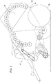
- FIG. 1 shows a schematic representation of a first embodiment of the inventive round agricultural baler.
- schematically illustrated round baler 10 comprises a housing 12 with a housing part 14 which is supported by means of wheels 16 on a floor 18 and by means of a drawbar 20 to a towing vehicle, not shown, for. B. a tractor or farm tractor, can be connected.
- a receiving and feeding device 22 for crop At the front in the forward direction of the lower side of the housing part 14 is located in a known manner, a receiving and feeding device 22 for crop.
- the housing 12 further has a housing flap 14 about a bearing axis pivotally mounted ejector flap 26, wherein in particular at the rear upper corner portion of the housing part 14, a bearing for the pivotally mounted ejector flap 26 is located.
- drivable pressing means 28 are distributed, which limit a baling chamber 24 circumferentially and through which a rotation-generating or rotation-maintaining engagement effect on a located in the baling chamber 24 round bales 30 can be generated.
- the housing part 14 forms a front part of the baling chamber 24 and the ejection flap 26 forms a rear part of the baling chamber 24.
- the round baler 10, formed with size-variable baling chamber 24, contains a plurality of mutually parallel pressing elements 28 for pressing crop in the form of press rollers 32 (only a few press rollers 32 have been provided with the reference numeral "32"), their axes of rotation 34 when closed Discharge flap 26 are located on a circular arc, and at least some of which are driven.
- the ejection flap 26 can be actuated (opened and closed) by means of an adjusting device (not shown), for example by means of one or more servomotors.
- the ejection flap 26 is pivotable by means of the adjusting device such that when opening the ejection flap 26, an ejection opening 36 between the housing part 14 and the ejection flap 26 can be formed.
- a pressed by the round baler 10 bale 28 can be discontinued or unloaded or ejected.
- the round bale 30 thereby moves in the direction of the ejection opening 36 and rolls onto a roll-off or unloading ramp 38, via which the round bale 30 can be guided onto the floor 18.
- the ejection flap 26 is pivotable by means of the adjusting device such that a dimension 40 of the ejection opening, preferably a diameter of the ejection opening and / or a distance between the housing part 14 and the ejection flap 26, is variable.
- the round baler 10 further has a drive assembly 42 with a gear assembly 44, a first drive train 46 and a second drive train 48.
- a drive shaft 50 is connected to a PTO (not shown) of the towing vehicle or tractor and serves as a drive for the drive assembly 36th Der
- the first drive train 46 is connected via a first output (not shown) and the second drive train 48 via a second output (not shown) of the gear assembly 44 with this in drive connection.
- the first drive train 46 drives the receiving and feeding device 22, the second drive train 48 being provided for driving the pressing means 28 or the pressing rollers 32.
- the drive trains 46, 48 include all drive components which are arranged in known manner in round balers for driving the receiving and feeding device 22 and for driving the pressing means 28 and the drive side are connected to the first output and the second output of the gear assembly 44.
- the round baler 10 comprises a winding device 56 which is equipped with a net or film roll 52 as a wrapping material.
- the winding device 56 comprises a wrapping material feed 54 which guides the wrapping material from the web or film roll 52 into the baling chamber 24.
- a binding device (not shown) with twine, also in a known manner, can be used.
- the first and the second drive train 46, 48 are driven in parallel via the gear assembly 44 and via the drive and the drives, so that the receiving and feeding device 22 and the pressing means 28, 32 at the same time with constant speed ratio to each other in operation being held.
- the drive over the bottom 18 is interrupted, since the round baler 10 is filled with the round bale 30 and no more crop is to be included in the baling chamber 24 or can .
- the winding device 56 is activated, which initiates a winding or binding process.
- the wrapping material is wound around the round bale 30 by a sustained rotation of the bale located in the baling chamber 24 round bale.
- the pressing operation is transferred to the unloading operation, and the round bale is discharged onto the bottom 18 through the discharge opening and the unloading ramp 38 by opening the discharge door 26.
- a significant problem during the unloading process is the safe unloading of the round bale, especially in uneven and / or hilly terrain, as the round bales in this area either continue to roll and / or even fall over and are thus not unloaded at the desired storage location. For this reason, the operator must first find a suitable storage location in uneven and / or hilly terrain to safely unload the round bale, which is very time consuming and associated with considerable effort.
- the ejector flap 26 during a discharge of the finished round bales 30 by means of the adjusting device such that the open ejection flap 26 from an unloading position (see FIG. 2 ), in which the finished round bale 30 is discharged through the discharge opening 36, is movable to a holding position in which the discharged round bale 30 is held by means of the opened discharge flap 26 (see FIG FIG. 3 ).
- the ejection flap 26 can be adjusted such that the opened ejection flap 26 is movable from the holding position into a release position in which the held round bale 30 is released from the opened ejection flap 26 (see FIG Figures 3 and 4 ).
- the round bale 30 can thus be held in a simple manner and safely unloaded at the desired storage location. Unintentional rolling of the round bale 30 in uneven and / or hilly terrain can thus be prevented and the round bale 30 can be unloaded in a simple way in uneven and / or hilly terrain.
- the service life of the round baler 10 is significantly shortened, and the unloading process is made less complicated. It can be retracted so 30 more round bales per unit time.
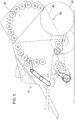
- FIG. 2 shows a schematic side view of the first embodiment of the inventive round agricultural baler 10 in an unloading position.
- FIG. 3 shows a schematic side view of the first embodiment of the inventive round agricultural baler 10 in a holding position.
- FIG. 4 shows a schematic side view of the first embodiment of the inventive round agricultural baler 10 in a discharge position.
- the in the Figures 2 . 3 and 4 shown round baler 10 substantially corresponds to in FIG. 1 round baler 10 shown so that only the differences will be discussed below.
- the ejection flap 26 of the round baler 10 is adjustable by means of the adjusting device such that the dimension 40 of the ejection opening 36 in the holding position (see FIG. 3 ) is smaller than in the unloading position (see FIG.
- the discharge flap 26 can be adjusted during the unloading process of the finished round bale 30 by means of the setting device such that, when the discharge flap is open, the dimension of the discharge opening for unloading a finished pressed round bale is first is increased, the dimension is then reduced to hold the discharged round bale with the ejector flap opened, and the dimension is then increased to letting go of the round bale again.
- the round baler according to the invention is thus configured in such a simple and constructional manner that the unloading process can be carried out in uneven and / or hilly terrain and less time-consuming unloading of the round bale is possible.
- FIG. 5 shows a schematic side view of a second embodiment of the inventive round agricultural baler 10.
- Die in FIG. 5 shown round baler 10 corresponds substantially to the in the FIGS. 1 to 4 round baler 10 shown so that only the differences will be discussed below.
- the ejection flap 26 comprises directly at the ejection opening 36 a freely rotatably mounted holding roller 58 for holding the round bale 30, wherein the freely rotatably mounted holding roller 58 for holding the round bale can also be arranged on the housing part 14 directly to the ejection opening 36.
Landscapes
- Life Sciences & Earth Sciences (AREA)
- Environmental Sciences (AREA)
- Storage Of Harvested Produce (AREA)
- Harvester Elements (AREA)
Abstract
Description
- Die Erfindung betrifft eine landwirtschaftliche Rundballenpresse gemäss dem Oberbegriff des unabhängigen Anspruchs 1 und ein Verfahren zum Betrieb einer landwirtschaftlichen Rundballenpresse gemäss dem Oberbegriff des unabhängigen Anspruchs 6.
- Landwirtschaftliche Rundballenpressen sind bekannt. Dabei wird in Rundballenpressen landwirtschaftliches Erntegut, beispielsweise Stroh, Gras oder Getreide zu einem Rundballen geformt und mit einem Umwicklungsmaterial, beispielsweise Netz, Folie oder Bindegarn, umwickelt. Derartige Rundballenpressen weisen eine Aufnahme- und Zuführeinrichtung für das zu pressende Erntegut auf, durch welche das Erntegut in eine Zuführöffnung einer Ballenpresskammer eingeführt wird. Die Rundballenpresse umfasst ein Gehäuse, wobei das Gehäuse insbesondere zweigeteilt ausgebildet sein kann. Das Gehäuse kann ausserdem auf einem Fahrgestell angeordnet sein. Das Gehäuse weist einen Gehäuseteil, insbesondere einen fahrgestellfesten Gehäuseteil, und eine an diesem Gehäuseteil um eine Lagerachse aufschwenkbar, gelagerte Auswurfklappe auf. Im Speziellen befindet sich am rückwärtigen oberen Eckbereich des Gehäuseteils ein Lager, an welchem die Auswurfklappe schwenkbar gelagert sein kann.
- Die Ballenpresskammer umfasst eines oder mehrere Pressmittel, die auf oder an dem Gehäuseteil und der Auswurfklappe verteilt sind und die Ballenpresskammer umfangsseitig begrenzen. Somit bildet das Gehäuseteil einen vorderen Teil der Ballenpresskammer und die Auswurfklappe einen hinteren Teil der Ballenpresskammer aus. Mittels des Pressmittels ist eine rotationserzeugende oder rotationserhaltende Eingriffswirkung auf einen in der Ballenpresskammer befindlichen Rundballen erzeugbar. Die Auswurfklappe ist mittels einer Stelleinrichtung derart schwenkbar, dass beim Öffnen der Auswurfklappe eine Auswurföffnung zwischen dem Gehäuseteil und der Auswurfklappe ausbildbar ist. Darüber hinaus ist mittels der Stelleinrichtung eine Abmessung der Auswurföffnung veränderbar, bevorzugt einstellbar.
- Am Anfang eines Entladevorgangs, also nach dem Ende eines Pressvorgangs, erfolgt das Öffnen der Auswurföffnung, also bevorzugt, wenn der Rundballen fertig gepresst ist, die erforderliche Grösse erreicht hat und entladen werden kann. Während des Entladevorgangs wird die Abmessung der Auswurföffnung und die Anordnung der Pressmittel, also eine Geometrie der Ballenpresskammer, derart verändert, dass der Rundballen entladen werden kann. Dabei kann insbesondere auch die Geometrie zwischen den unmittelbar an der Auswurföffnung befindlichen Pressmitteln verändert werden, um den Rundballen zu entladen.
- Ein wesentliches Problem beim Entladevorgang ist das sichere Entladen des Rundballens, in unebenem und/oder hügeligem Gelände, da der Rundballen in diesem Gelände nach dem Entladen weiterrollen und somit nicht am aktuellen Arbeitsort entladen werden kann. Aus diesem Grund muss der Bediener der Rundballenpresse in unebenem und/oder hügeligem Gelände das Sammeln des Ernteguts am aktuellen Arbeitsort zunächst unterbrechen, einen geeigneten Lagerort suchen, insbesondere ein flaches Gelände, den geeigneten Lagerort anfahren und dort den Rundballen entladen, um anschliessend wieder an den aktuellen Arbeitsort zurückzukehren. Dieser Vorgang ist sehr zeitaufwändig und mit erheblichem Aufwand verbunden. Im Weiteren ist die bekannte Rundballenpresse konstruktiv und verfahrenstechnisch nicht dazu ausgelegt einen Entladevorgang in unebenem und/oder hügeligem Gelände zu ermöglichen. Darüber hinaus erhöht ein Öffnen der Auswurfklappe während des Entladevorgangs, insbesondere ein automatisches Öffnen der Auswurfklappe, in unebenem und/oder hügeligem Gelände die Unfallgefahr, da der Rundballen ungewollt weiterrollen kann.
- Ausgehend von diesem Stand der Technik ist es daher eine Aufgabe der vorliegenden Erfindung eine Rundballenpresse und ein Verfahren zum Betrieb einer Rundballenpresse vorzuschlagen, die die aus dem Stand der Technik bekannten Nachteile weitgehend vermeiden, insbesondere eine Rundballenpresse und ein Verfahren zum Betrieb einer Rundballenpresse vorzuschlagen, die konstruktiv und verfahrenstechnisch einfach ausgestaltet sind und/oder ein einfaches, unfallfreies und/oder weniger zeitaufwändiges Entladen des Rundballens, insbesondere in unebenem und/oder hügeligem Gelände ermöglichen.
- Diese Aufgabe wird durch eine landwirtschaftliche Rundballenpresse mit den Merkmalen des Anspruchs 1 und ein Verfahren zum Betrieb einer landwirtschaftlichen Rundballenpresse mit den Merkmalen des Anspruchs 6 gelöst.
- Die abhängigen Ansprüche beziehen sich auf besonders vorteilhafte Ausführungsformen der Erfindung.
- Erfindungsgemäß ist die Auswurfklappe einer landwirtschaftlichen Rundballenpresse der eingangs genannten Art während eines Entladevorgangs des fertig gepressten Rundballen mittels der Stelleinrichtung derart einstellbar, dass die geöffnete Auswurfklappe von einer Entladeposition, in welcher der fertig gepresste Rundballen durch die Auswurföffnung entladen wird, in eine Halteposition beweglich ist, in welcher der entladene Rundballen mittels der geöffneten Auswurfklappe gehalten wird, und von der Halteposition in eine Entlastungsposition beweglich ist, in welcher der gehaltene Rundballen von der geöffneten Auswurfklappe losgelassen wird.
- Wesentlich für die Erfindung ist die spezielle Ausbildung und Einstellbarkeit der Auswurfklappe während des Entladevorgangs. Diese bewirkt, dass der fertig gepresste und durch die Auswurföffnung in der Entladeposition entladene Rundballen mittels der geöffneten Auswurfklappe in der Halteposition in unebenem und/oder hügeligem Gelände haltbar ist. Der Rundballen kann dabei solange mittels der geöffneten Auswurfklappe in der Halteposition haltbar sein, bis der Rundballen keinerlei translatorische oder kinetische Energie mehr aufweist und in unebenem und/oder hügeligem Gelände abstellbar, insbesondere lagerbar ist. Anschliessend ist der Rundballen von der Halteposition in eine Entlastungsposition beweglich, in welcher der gehaltene und ruhende Rundballen von der geöffneten Auswurfklappe losgelassen wird. Vorteilhafterweise kann der Rundballen somit auf einfache Art und Weise gehalten und sicher am gewünschten Lagerort in unebenem und/oder hügeligem Gelände abgeladen werden. Ein unbeabsichtigtes Rollen des Rundballens nach dem Entladen kann also verhindert werden, sodass die Unfallgefahr reduziert wird. Damit kann der Rundballen ohne aufwändiges Unterbrechen des Sammelvorgangs, also ohne Zeitverlust, direkt am Arbeitsort in unebenem und/oder hügeligem Gelände abgeladen werden. Mit anderen Worten, die Standzeit der Rundballenpresse wird deutlich verkürzt und der Entladevorgang wird wenig aufwändig ausgestaltet. Es können also mehr Rundballen pro Zeiteinheit eingefahren werden.
- Die Rundballenpresse kann eine größenunveränderliche Ballenpresskammer umfassen. Hierbei kann das Pressmittel als Pressrolle ausgebildet sein, insbesondere eine Vielzahl zueinander parallel verlaufender Pressrollen zum Pressen des Ernteguts. Die Rotationsachsen der Pressrollen können bei geschlossener Auswurfklappe auf einem Kreisbogen liegen und wenigstens eine der Pressrollen kann angetrieben sein. Die Anordnung der Pressrollen im Ballenpressraum kann einer Zylinderform entsprechen, sodass die Pressrollen zylindrisch um den Rundballen angeordnet sind und eine zylindrische Umfangsfläche ausbilden. Alternativ kann die Rundballenpresse auch mit einer größenveränderlichen Ballenpresskammer bzw. als Rundballenpresse mit variabler Ballenpresskammer ausgebildet sein, wobei die Pressmittel dann als Riemen, Gurte oder Kettenanordnungen ausgebildet sein können.
- Der Entladevorgang kann mit dem Öffnen der Auswurfklappe beginnen und mit dem Schliessen der Auswurfklappe, nach dem Entladen und Halten des fertig gepressten Rundballens, enden. Die Auswurfklappe kann während des Entladevorgangs mittels der Stelleinrichtung zwischen der Entladeposition, der Halteposition und der Entlastungsposition beweglich sein, wobei die Auswurfklappe insbesondere von der Entladeposition in die Halteposition und anschliessend in die Entlastungsposition beweglich ist. Die Stelleinrichtung kann dabei als Stellmotor ausgebildet sein.
- In Ausgestaltung der Erfindung ist die Auswurfklappe mittels der Stelleinrichtung derart einstellbar, dass die Abmessung der Auswurföffnung in der Halteposition kleiner ist als in der Entladeposition und die Abmessung der Auswurföffnung in der Entlastungsposition grösser ist als die Abmessung in der Halteposition. Die Abmessung der Auswurföffnung kann ein Durchmesser der Auswurföffnung oder ein Abstand zwischen dem Gehäuseteil und der Auswurfklappe sein, zwischen welchen die Auswurföffnung ausbildbar ist.
Da in der Entladeposition der fertig gepresste Rundballen durch die Auswurföffnung entladbar sein soll, kann in dieser Position die Abmessung der Auswurföffnung grösser als ein Rundballendurchmesser des fertig gepressten Rundballens sein. In der Halteposition kann die Abmessung der Auswurföffnung kleiner als der Rundballendurchmesser sein, da in der Halteposition der fertig gepresste und entladene Rundballen von der geöffneten Auswurfklappe gehalten wird. In der Entlastungsposition wiederum kann die Abmessung der Auswurföffnung grösser als der Rundballendurchmesser sein, da der gehaltene Rundballen von der geöffneten Auswurfklappe losgelassen wird. Die Abmessung der Auswurföffnung kann in der Entlastungsposition wenigstens der Abmessung in der Entladeposition entsprechen. Die Entladeposition kann aber auch eine maximale Abmessung und/oder in der Entlastungsposition eine kleiner Abmessung als in der Entladeposition aufweisen.
Mit anderen Worten, die Auswurfklappe ist während eines Entladevorgangs des fertig gepressten Rundballen mittels der Stelleinrichtung derart einstellbar, dass die Abmessung der Auswurföffnung zum Entladen eines fertig gepressten Rundballens zunächst vergrößert wird (Entladeposition), die Abmessung anschliessend zum Halten des entladenen Rundballens mit der geöffneten Auswurfklappe verkleinert wird (Halteposition), und die Abmessung danach zum Loslassen des Rundballens wieder vergrössert wird (Entlastungsposition). Vorteilhafterweise wird somit das sichere Entladen des Rundballens beim Entladevorgang in unebenem und/oder hügeligem Gelände ermöglicht. Es wird verhindert, dass der entladene Rundballen Entladevorgang in unebenem und/oder hügeligem Gelände nach dem Entladen weiterrollen und/oder umfallen kann und ein Entladen am aktuellen Arbeitsort ermöglicht wird. Der Bediener der Rundballenpresse muss also das Sammeln des landwirtschaftlichen Ernteguts am aktuellen Arbeitsort in unebenem und/oder hügeligem Gelände nicht unterbrechen. Der Zeitaufwand des Entladevorgangs und darüber hinaus die Unfallgefahr während des Entladevorgangs in unebenem und/oder hügeligem Gelände wird reduziert. - In Ausgestaltung der Erfindung umfasst die Auswurfklappe und/oder das Gehäuseteil unmittelbar an der Auswurföffnung eine frei drehbar gelagerte Halterolle zum Halten des Rundballens. Die Halterolle kann an der Auswurfklappe und/oder dem Gehäuseteil unmittelbar an der Auswurföffnung angeordnet und/oder befestigt sein. Aufgrund dieser Maßnahme hält bei geöffneter Auswurfklappe, insbesondere in der Halteposition, die frei drehbar gelagerte Halterolle den aus der Ballenpresskammer entladenen Rundballen. Der entladene Rundballen kann aber auch mittels der Halterolle an der Auswurfklappe entlanggleiten und gleichzeitig gehalten werden. Die Abmessung der Auswurfklappe in der Halteposition kann dabei unterschiedlich sein, insbesondere kann sich die Abmessung während der Halteposition, beispielsweise von einem zeitlichen Start der Halteposition bis zu einem zeitlichen Ende der Halteposition, vergrössern. Somit kann vorteilhafterweise auf zusätzliche Mittel zum Halten des Rundballens, beispielsweise eine aussen an der Auswurfklappe angeordnete Stützrolle, verzichtet werden.
- In Ausgestaltung der Erfindung weist die Rundballenpresse einen Neigungssensor zur Messung einer Neigung der Rundballenpresse und/oder ein Kommunikationsmodul zum Empfang einer Standortinformation der Rundballenpresse auf. Ausserdem ist die Stelleinrichtung in Abhängigkeit von der Neigung und/oder der Standortinformation der Rundballenpresse betreibbar. Mit dem Neigungssensor kann die Neigung gemessen werden, insbesondere ein Neigungswinkel der Rundballenpresse in Bezug zur Lotrichtung oder eine Änderung eines Neigungswinkels und/oder der Neigungswinkel in Bezug zur Gravitation der Erde. Die Standortinformation der Rundballenpresse kann die eigene Position der Rundballenpresse auf der Erdoberfläche oder in einem geeigneten geometrischen Bezugssystem sein. Die Standortinformation kann beispielsweise mittels des globalen Positionsbestimmungssystem (engl. Global Positioning System=GPS) ermittelt werden und mittels des Kommunikationsmoduls bereitgestellt bzw. empfangen werden. Das Kommunikationsmodul kann ein GPS-Gerät und/oder ein WLAN-Gerät und/oder ein Tablet und/oder Smartphone sein. Die Neigung und/oder die Standortinformation geben Auskunft darüber, ob sich die Rundballenpresse, insbesondere der aktuelle Arbeitsort der Rundballenpresse, in unebenem und/oder hügeligem Gelände befindet. Vorteilhafterweise kann somit die Stelleinrichtung in Abhängigkeit von der Neigung und/oder der Standortinformation der Rundballenpresse, also in Abhängigkeit vom aktuellen Arbeitsort, betrieben werden. Darüber hinaus können die Entladeposition und/oder die Halteposition und/oder die Entlastungsposition in Abhängigkeit von der Neigung und/oder der Standortinformation der Rundballenpresse eingestellt werden. In beiden Fällen kann ein sicheres Entladen des Rundballens in unebenem und/oder hügeligem Gelände gewährleistet werden, was konstruktiv auf einfache Art und Weise durch das Vorsehen eines Neigungssensors und/oder Kommunikationsmoduls gelöst wird.
- Die Erfindung betrifft weiter ein Verfahren zum Betrieb einer landwirtschaftlichen Rundballenpresse mit einem Gehäuse, insbesondere ein Entladeverfahren für eine Rundballenpresse. Das Gehäuse weist einen Gehäuseteil und eine an diesem Gehäuseteil um eine Lagerachse schwenkbar gelagerte Auswurfklappe auf. Die Rundballenpresse umfasst weiter auf dem Gehäuseteil und der Auswurfklappe verteilte angetriebene Pressmittel, die eine Ballenpresskammer umfangsseitig begrenzen und durch welche eine rotationserzeugende oder rotationserhaltene Eingriffswirkung auf einen in der Ballenpresskammer befindlichen Rundballen erzeugt wird. Die Auswurfklappe wird mittels einer Stelleinrichtung derart geschwenkt, dass beim Öffnen der Auswurfklappe eine Auswurföffnung zwischen dem Gehäuseteil und der Auswurfklappe ausgebildet wird und eine Abmessung der Auswurföffnung verändert, insbesondere eingestellt, wird. Dabei wird die Auswurfklappe während eines Entladevorgangs des fertig gepressten Rundballen mittels der Stelleinrichtung derart eingestellt, dass die geöffnete Auswurfklappe von einer Entladeposition, in welcher der fertig gepresste Rundballen durch die Auswurföffnung entladen wird, in eine Halteposition bewegt wird, in welcher der entladene Rundballen mittels der geöffneten Auswurfklappe gehalten wird, und von der Halteposition in eine Entlastungsposition bewegt wird, in welcher der gehaltene Rundballen von der geöffneten Auswurfklappe losgelassen wird.
- Das erfindungsgemässe Verfahren weist die oben beschriebenen Vorteile der erfindungsgemässen Rundballenpresse auf. Im Weiteren kann die erfindungsgemässe Rundballenpresse bei der Durchführung des erfindungsgemässen Verfahrens verwendet werden.
- Im Folgenden werden die Erfindung sowie weitere Vorteile und vorteilhafte Weiterbildungen und Ausgestaltungen der Erfindung sowohl in apparativer als auch in verfahrenstechnischer Hinsicht anhand von Ausführungsbeispielen und unter Bezugnahme auf die Zeichnung näher erläutert. Dabei sind hinsichtlich ihrer Funktion übereinstimmende bzw. vergleichbare Bauteile mit denselben Bezugszeichen gekennzeichnet. In den schematischen Zeichnungen zeigen:
- Fig. 1
- eine schematische Seitenansicht eines ersten Ausführungsbeispiel einer erfindungsgemässen landwirtschaftlichen Rundballenpresse mit Pressrollen und Auswurföffnung zum Entladen eines gepressten Rundballens, und
- Fig. 2
- eine schematische Seitenansicht des ersten Ausführungsbeispiel der erfindungsgemässen landwirtschaftlichen Rundballenpresse in einer Entladeposition, und
- Fig. 3
- eine schematische Seitenansicht des ersten Ausführungsbeispiel der erfindungsgemässen landwirtschaftlichen Rundballenpresse in einer Halteposition, und
- Fig. 4
- eine schematische Seitenansicht des ersten Ausführungsbeispiel der erfindungsgemässen landwirtschaftlichen Rundballenpresse in einer Entlastungsposition, und
- Fig. 5
- eine schematische Seitenansicht eines zweiten Ausführungsbeispiel der erfindungsgemässen landwirtschaftlichen Rundballenpresse.
-
Figur 1 zeigt eine schematische Darstellung eines ersten Ausführungsbeispiels der erfindungsgemässen landwirtschaftlichen Rundballenpresse. Die inFigur 1 schematisch dargestellte Rundballenpresse 10 umfasst ein Gehäuse 12 mit einem Gehäuseteil 14, der sich mittels Rädern 16 auf einem Boden 18 abstützt und mittels einer Deichsel 20 an ein nicht gezeigtes Zugfahrzeug, z. B. einen Traktor oder Ackerschlepper, anschließbar ist. - An der in Vorwärtsfahrtrichtung vorderen unteren Seite des Gehäuseteils 14 befindet sich in bekannter Weise eine Aufnahme- und Zuführeinrichtung 22 für Erntegut.
- Das Gehäuse 12 weist weiter eine am Gehäuseteil 14 um eine Lagerachse schwenkbar gelagerte Auswurfklappe 26 auf, wobei sich im Speziellen am rückwärtigen oberen Eckbereich des Gehäuseteils 14 ein Lager für die schwenkbar gelagerte Auswurfklappe 26 befindet. Auf dem Gehäuseteil 14 und der Auswurfklappe 26 sind antreibbare Pressmittel 28 verteilt, die eine Ballenpresskammer 24 umfangsseitig begrenzen und durch welche eine rotationserzeugende oder rotationserhaltende Eingriffswirkung auf einen in der Ballenpresskammer 24 befindlichen Rundballen 30 erzeugbar ist. Somit bildet das Gehäuseteil 14 einen vorderen Teil der Ballenpresskammer 24 und die Auswurfklappe 26 einen hinteren Teil der Ballenpresskammer 24 aus.
- Die Rundballenpresse 10, mit größenunveränderlicher Ballenpresskammer 24 ausgebildet, enthält eine Vielzahl zueinander parallel verlaufender Presselemente 28 zum Pressen von Erntegut in Form von Pressrollen 32 (exemplarisch wurden hier nur einige wenige Pressrollen 32 mit dem Bezugszeichen "32" versehen), deren Rotationsachsen 34 bei geschlossener Auswurfklappe 26 auf einem Kreisbogen gelegen sind, und von denen wenigstens einige angetrieben sind.
- Die Auswurfklappe 26 kann mittels einer Stelleinrichtung (nicht gezeigt), beispielsweise mittels einem oder mehreren Stellmotoren, betätigt werden (geöffnet und geschlossen werden). Dabei ist die Auswurfklappe 26 mittels der Stelleinrichtung derart schwenkbar, dass beim Öffnen der Auswurfklappe 26 eine Auswurföffnung 36 zwischen dem Gehäuseteil 14 und der Auswurfklappe 26 ausbildbar ist. Durch die Auswurföffnung 36 kann ein von der Rundballenpresse 10 gepresster Ballen 28 abgesetzt bzw. entladen oder ausgeworfen werden. Der Rundballen 30 bewegt sich dabei in Richtung der Auswurföffnung 36 und rollt auf eine Abroll- oder Entladerampe 38, über welche der Rundballen 30 auf den Boden 18 geleitet werden kann. Darüber hinaus ist die Auswurfklappe 26 mittels der Stelleinrichtung derart schwenkbar, dass eine Abmessung 40 der Auswurföffnung, bevorzugt ein Durchmesser der Auswurföffnung und/oder ein Abstand zwischen dem Gehäuseteil 14 und der Auswurfklappe 26, veränderbar ist.
- Die Rundballenpresse 10 verfügt ferner über eine Antriebsanordnung 42 mit einer Getriebeanordnung 44, einem ersten Antriebsstrang 46 und einem zweiten Antriebsstrang 48. Eine Antriebswelle 50 ist mit einer Zapfwelle (nicht gezeigt) des Zugfahrzeugs oder Schleppers verbindbar und dient als Antrieb für die Antriebsanordnung 36. Der erste Antriebsstrang 46 steht über einen ersten Abtrieb (nicht gezeigt) und der zweite Antriebsstrang 48 über einen zweiten Abtrieb (nicht gezeigt) der Getriebeanordnung 44 mit dieser in Antriebsverbindung. Der erste Antriebsstrang 46 treibt die Aufnahme- und Zuführeinrichtung 22 an, wobei der zweite Antriebsstrang 48 zum Antreiben der Pressmittel 28 bzw. der Pressrollen 32 vorgesehen ist. Die Antriebsstränge 46, 48 umfassen alle Antriebskomponenten, die in bekannter Weise in Rundballenpressen zum Antreiben der Aufnahme- und Zuführeinrichtung 22 bzw. zum Antreiben der Pressmittel 28 angeordnet sind und antriebsseitig mit dem ersten Abtrieb bzw. dem zweiten Abtrieb der Getriebeanordnung 44 verbunden sind.
- Ferner umfasst die Rundballenpresse 10 eine Wickelvorrichtung 56, die mit einer Netz- oder Folienrolle 52 als Wickelmaterial bestückt ist. Die Wickelvorrichtung 56 umfasst eine Wickelmaterialzuführung 54, die das Wickelmaterial von der Netz- bzw. Folienrolle 52 in den Ballenpresskammer 24 führt. An Stelle einer Wickelvorrichtung 56 kann auch eine Bindevorrichtung (nicht gezeigt) mit Bindegarn, ebenfalls in bekannter Weise, zum Einsatz kommen.
- Während eines Pressvorgangs werden der erste und der zweite Antriebsstrang 46, 48 über die Getriebeanordnung 44 bzw. über den Antrieb und den Abtrieben parallel angetrieben, so dass die Aufnahme- und Zuführeinrichtung 22 als auch die Pressmittel 28, 32 zeitgleich mit konstantem Drehzahlverhältnis zueinander in Betrieb gehalten werden. Nachdem die Erntegutaufnahme und Bildung des Rundballens 30 durch die Pressrollen 32, abgeschlossen ist, wird die Fahrt über den Boden 18 unterbrochen, da die Rundballenpresse 10 mit dem Rundballen 30 gefüllt ist und kein weiteres Erntegut mehr in die Ballenpresskammer 24 aufgenommen werden soll bzw. kann. Zu dieser Zeit wird auch die Wickelvorrichtung 56 aktiviert, die einen Wickel- bzw. Bindevorgang eingeleitet. Dabei wird durch eine anhaltende Drehung des sich in der Ballenpresskammer 24 befindlichen Rundballens das Wickelmaterial um den Rundballen 30 gewickelt. Nachdem ein Wickelvorgang abgeschlossen ist geht der Pressvorgang in den Entladevorgang über und der Rundballen wird während durch Öffnen der Auslassklappe 26 über die Auswurföffnung und die Entladerampe 38 auf den Boden 18 abgelassen.
- Ein wesentliches Problem beim Entladevorgang ist das sichere Entladen des Rundballens, insbesondere in unebenem und/oder hügeligem Gelände, da der Rundballen in diesem Gelände entweder weiterrollen und/oder sogar umfallen und somit nicht am gewünschten Lagerort entladen werden. Aus diesem Grund muss der Bediener in unebenem und/oder hügeligem Gelände zunächst einen geeigneten Lagerort suchen, um den Rundballen sicher zu entladen, was sehr zeitaufwändig und mit erheblichem Aufwand verbunden ist. Um den Entladevorgang der Rundballenpresse 10 in unebenem und/oder hügeligem Gelände gegenüber herkömmlichen Rundballenpressen 10 dennoch zu ermöglichen, ist es bei der hier ausgebildeten Rundballenpresse 10 möglich, die Auswurfklappe 26 während eines Entladevorgangs des fertig gepressten Rundballen 30 mittels der Stelleinrichtung derart einstellbar, dass die geöffnete Auswurfklappe 26 von einer Entladeposition (siehe
Figur 2 ), in welcher der fertig gepresste Rundballen 30 durch die Auswurföffnung 36 entladen wird, in eine Halteposition beweglich ist, in welcher der entladene Rundballen 30 mittels der geöffneten Auswurfklappe 26 gehalten wird (sieheFigur 3 ). Im Weiteren ist die Auswurfklappe 26 während des Entladevorgangs des fertig gepressten Rundballen 30 mittels der Stelleinrichtung derart einstellbar, dass die geöffnete Auswurfklappe 26 von der Halteposition in eine Entlastungsposition beweglich ist, in welcher der gehaltene Rundballen 30 von der geöffneten Auswurfklappe 26 losgelassen wird (sieheFiguren 3 und4 ). Vorteilhafterweise kann der Rundballen 30 somit auf einfache Art und Weise gehalten und sicher am gewünschten Lagerort abgeladen werden. Ein unbeabsichtigtes Rollen des Rundballens 30 in unebenem und/oder hügeligem Gelände kann also verhindert werden und der Rundballen 30 kann auf einfache Art in unebenem und/oder hügeligem Gelände ausgeladen werden. Mit anderen Worten, die Standzeit der Rundballenpresse 10 wird deutlich verkürzt, und der Entladevorgang wird weniger aufwändig ausgestaltet. Es können so mehr Rundballen 30 pro Zeiteinheit eingefahren werden. -
Figur 2 zeigt eine schematische Seitenansicht des ersten Ausführungsbeispiels der erfindungsgemässen landwirtschaftlichen Rundballenpresse 10 in einer Entladeposition.Figur 3 zeigt eine schematische Seitenansicht des ersten Ausführungsbeispiels der erfindungsgemässen landwirtschaftlichen Rundballenpresse 10 in einer Halteposition.Figur 4 zeigt eine schematische Seitenansicht des ersten Ausführungsbeispiels der erfindungsgemässen landwirtschaftlichen Rundballenpresse 10 in einer Entlastungsposition. Die in denFiguren 2 ,3 und4 gezeigte Rundballenpresse 10 entspricht im Wesentlichen der inFigur 1 gezeigten Rundballenpresse 10, sodass im Folgenden lediglich auf die Unterschiede eingegangen wird. Die Auswurfklappe 26 der Rundballenpresse 10 ist mittels der Stelleinrichtung derart einstellbar, dass die Abmessung 40 der Auswurföffnung 36 in der Halteposition (sieheFigur 3 ) kleiner ist als in der Entladeposition (sieheFigur 2 ) und die Abmessung 40 der Auswurföffnung 36 in der Entlastungsposition (sieheFigur 4 ) grösser ist als die Abmessung 40 in der Halteposition (sieheFigur 3 ). Mit anderen Worten, die Auswurfklappe 26 ist während des Entladevorgangs des fertig gepressten Rundballen 30 mittels der Stelleinrichtung derart einstellbar, dass bei geöffneter Auswurfklappe die Abmessung der Auswurföffnung zum Entladen eines fertig gepressten Rundballens zunächst vergrößert wird, die Abmessung anschliessend zum Halten des entladenen Rundballens mit der geöffneten Auswurfklappe verkleinert wird, und die Abmessung danach zum Loslassen des Rundballens wieder vergrössert wird. Die erfindungsgemässe Rundballenpresse ist somit konstruktiv und verfahrenstechnisch derart einfach ausgestaltet, dass der Entladevorgang in einem unebenen und/oder hügeligen Gelände ausführbar ist und ein weniger zeitaufwändiges Entladen des Rundballens möglich ist. -
Figur 5 zeigt eine schematische Seitenansicht eines zweiten Ausführungsbeispiels der erfindungsgemässen landwirtschaftlichen Rundballenpresse 10. Die inFigur 5 gezeigte Rundballenpresse 10 entspricht im Wesentlichen der in denFiguren 1 bis 4 gezeigten Rundballenpresse 10, sodass im Folgenden lediglich auf die Unterschiede eingegangen wird. Die Auswurfklappe 26 umfasst unmittelbar an der Auswurföffnung 36 eine frei drehbar gelagerte Halterolle 58 zum Halten des Rundballens 30, wobei die frei drehbar gelagerte Halterolle 58 zum Halten des Rundballens auch am Gehäuseteil 14 unmittelbar an der Auswurföffnung 36 angeordnet sein kann.
Claims (6)
- Landwirtschaftliche Rundballenpresse mit einem Gehäuse (12), das einen Gehäuseteil (14) und eine an diesem Gehäuseteil (14) um eine Lagerachse schwenkbar gelagerte Auswurfklappe (26) aufweist, und auf dem Gehäuseteil (14) und der Auswurfklappe (26) verteilte antreibbare Pressmittel (28,32), die eine Ballenpresskammer (24) umfangsseitig begrenzen und durch welche eine rotationserzeugende oder rotationserhaltende Eingriffswirkung auf einen in der Ballenpresskammer (24) befindlichen Rundballen (30) erzeugbar ist,
wobei die Auswurfklappe (26) mittels einer Stelleinrichtung derart schwenkbar ist, dass beim Öffnen der Auswurfklappe (26) eine Auswurföffnung (36) zwischen dem Gehäuseteil (14) und der Auswurfklappe (26) ausbildbar ist und eine Abmessung (40) der Auswurföffnung (36) veränderbar ist,
dadurch gekennzeichnet, dass
die Auswurfklappe (26) während eines Entladevorgangs des fertig gepressten Rundballen (30) mittels der Stelleinrichtung derart einstellbar ist, dass die geöffnete Auswurfklappe (26) von einer Entladeposition, in welcher der fertig gepresste Rundballen (30) durch die Auswurföffnung (36) entladen wird, in eine Halteposition beweglich ist, in welcher der entladene Rundballen (30) mittels der geöffneten Auswurfklappe (26) gehalten wird, und von der Halteposition in eine Entlastungsposition beweglich ist, in welcher der gehaltene Rundballen (30) von der geöffneten Auswurfklappe (26) losgelassen wird. - Landwirtschaftliche Rundballenpresse nach Anspruch 1, dadurch gekennzeichnet, dass die Auswurfklappe (26) mittels der Stelleinrichtung derart einstellbar ist, dass die Abmessung (40) der Auswurföffnung (36) in der Halteposition kleiner ist als in der Entladeposition und die Abmessung (40) der Auswurföffnung (36) in der Entlastungsposition grösser ist als die Abmessung (40) in der Halteposition.
- Landwirtschaftliche Rundballenpresse nach einem der Ansprüche 1 bis 2, dadurch gekennzeichnet, dass die Auswurfklappe (26) und/oder das Gehäuseteil (14) unmittelbar an der Auswurföffnung (36) eine frei drehbar gelagerte Halterolle (58) zum Halten des Rundballens (30) umfassen.
- Landwirtschaftliche Rundballenpresse nach einem der Ansprüche 1 bis 3, dadurch gekennzeichnet, dass die Rundballenpresse (10) einen Neigungssensor zur Messung einer Neigung der Rundballenpresse und/oder ein Kommunikationsmodul zum Empfang einer Standortinformation der Rundballenpresse aufweist.
- Landwirtschaftliche Rundballenpresse nach einem der Ansprüche 1 bis 4, dadurch gekennzeichnet, dass die Stelleinrichtung in Abhängigkeit von der Neigung und/oder der Standortinformation der Rundballenpresse betreibbar ist.
- Verfahren zum Betrieb einer landwirtschaftliche Rundballenpresse (10) mit einem Gehäuse (12), wobei das Gehäuse (12) einen Gehäuseteil (14) und eine an diesem Gehäuseteil (14) um eine Lagerachse schwenkbar gelagerte Auswurfklappe (26) aufweist, und auf dem Gehäuseteil (14) und der Auswurfklappe (26) verteilte angetriebene Pressmittel (28, 32), die eine Ballenpresskammer (24) umfangsseitig begrenzen und durch welche eine rotationserzeugende oder rotationserhaltende Eingriffswirkung auf einen in der Ballenpresskammer (24) befindlichen Rundballen (30) erzeugt wird, wobei die Auswurfklappe (26) mittels einer Stelleinrichtung derart geschwenkt wird, dass beim Öffnen der Auswurfklappe (26) eine Auswurföffnung (36) zwischen dem Gehäuseteil (14) und der Auswurfklappe (26) ausgebildet wird und eine Abmessung (40) der Auswurföffnung (36) verändert wird,
dadurch gekennzeichnet, dass
die Auswurfklappe (26) während eines Entladevorgangs des fertig gepressten Rundballens (30) mittels der Stelleinrichtung derart eingestellt wird, dass die geöffnete Auswurfklappe (26) von einer Entladeposition, in welcher der fertig gepresste Rundballen (30) durch die Auswurföffnung (36) entladen wird, in eine Halteposition bewegt wird, in welcher der entladene Rundballen (30) mittels der geöffneten Auswurfklappe (26) gehalten wird, und von der Halteposition in eine Entlastungsposition bewegt wird, in welcher der gehaltene Rundballen (30) von der geöffneten Auswurfklappe (26) losgelassen wird.
Applications Claiming Priority (1)
| Application Number | Priority Date | Filing Date | Title |
|---|---|---|---|
| DE102018206518.7A DE102018206518A1 (de) | 2018-04-26 | 2018-04-26 | Landwirtschaftliche Rundballenpresse und Verfahren zum Betrieb einer landwirtschaftlichen Rundballenpresse |
Publications (2)
| Publication Number | Publication Date |
|---|---|
| EP3560323A1 true EP3560323A1 (de) | 2019-10-30 |
| EP3560323B1 EP3560323B1 (de) | 2022-11-16 |
Family
ID=66182430
Family Applications (1)
| Application Number | Title | Priority Date | Filing Date |
|---|---|---|---|
| EP19169261.5A Active EP3560323B1 (de) | 2018-04-26 | 2019-04-15 | Landwirtschaftliche rundballenpresse und verfahren zum betrieb einer landwirtschaftlichen rundballenpresse |
Country Status (5)
| Country | Link |
|---|---|
| US (1) | US11382276B2 (de) |
| EP (1) | EP3560323B1 (de) |
| CN (1) | CN110402699B (de) |
| DE (1) | DE102018206518A1 (de) |
| RU (1) | RU2019108492A (de) |
Families Citing this family (2)
| Publication number | Priority date | Publication date | Assignee | Title |
|---|---|---|---|---|
| US20250048969A1 (en) * | 2023-08-09 | 2025-02-13 | Cnh Industrial America Llc | Round bale ejection automation |
| US12622361B2 (en) * | 2023-08-15 | 2026-05-12 | Cnh Industrial America Llc | Regenerative tailgate circuit |
Citations (4)
| Publication number | Priority date | Publication date | Assignee | Title |
|---|---|---|---|---|
| EP1446998A1 (de) * | 2003-02-15 | 2004-08-18 | Deere & Company | Vorrichtung zum Unterstützen des Austritts eines Rundballens |
| WO2014129890A1 (en) * | 2013-02-22 | 2014-08-28 | Forage Innovations B.V. | Baling chamber with pivotally mounted conveying unit |
| US20150257340A1 (en) * | 2014-03-13 | 2015-09-17 | Deere & Company | Gate position control of round bale discharge |
| EP3235368A1 (de) * | 2016-04-08 | 2017-10-25 | Deere & Company | Steuerungssystem für landwirtschaftliche ausrüstung |
Family Cites Families (19)
| Publication number | Priority date | Publication date | Assignee | Title |
|---|---|---|---|---|
| GB2196294B (en) | 1986-10-20 | 1991-01-23 | Deere & Co | Machine for forming cylindrical bales of crop |
| SU1759305A1 (ru) | 1990-04-25 | 1992-09-07 | Тюменский Сельскохозяйственный Институт | Рулонный пресс-подборщик сеносоломистых материалов |
| US6622455B2 (en) * | 2000-09-12 | 2003-09-23 | Agco Corporation | Round baler with semi-automatically sequenced operating cycles and selectively variable point of operator intervention |
| ES2462534T3 (es) * | 2001-03-22 | 2014-05-23 | Welmount Limited | Combinación de máquina embaladora/envolvedora de balas |
| DE102004022801A1 (de) * | 2004-05-08 | 2005-12-15 | Deere & Company, Moline | Rundballenpresse |
| DE102006011134A1 (de) | 2006-03-10 | 2007-09-27 | Deere & Company, Moline | Steuereinrichtung |
| AU2013249982B2 (en) * | 2012-04-20 | 2016-07-28 | Forage Company B.V. | Continuous bale forming apparatus with a pivotal bale supporting construction |
| US8776679B1 (en) * | 2013-03-15 | 2014-07-15 | Cnh Industrial Canada, Ltd. | Semi-automatic bale ejection sequence |
| US8746137B1 (en) * | 2013-03-15 | 2014-06-10 | Cnh Industrial Canada, Ltd. | Calibration of baler tailgate cycle speed |
| DE102013108246A1 (de) * | 2013-08-01 | 2015-02-05 | Usines Claas France S.A.S. | Landwirtschaftliche Rundballenpresse |
| US9980437B2 (en) * | 2014-03-25 | 2018-05-29 | CNH Industrial American LLC | Baling system having a bale position sensor |
| NL2013286B1 (en) * | 2014-07-31 | 2016-09-21 | Forage Innovations Bv | Bale Forming Apparatus and Method with a Retaining Device. |
| US9622417B2 (en) * | 2015-05-01 | 2017-04-18 | Cnh Industrial America Llc | Tailgate motion adjustment system |
| NL2015525B1 (en) * | 2015-09-29 | 2017-04-20 | Forage Innovations Bv | Method and apparatus for forming round-cylindrical bales and depositing them on the ground at suitable locations. |
| WO2017201466A1 (en) * | 2016-05-19 | 2017-11-23 | Vermeer Manufacturing Company | Baling vehicle with automated pickup device height adjustment |
| EP3515177B1 (de) * | 2016-09-23 | 2020-07-29 | Lely Patent N.V. | Vorrichtung und verfahren für herstellung und auswurf eines ballens nach einem rampensensor |
| US10385605B2 (en) * | 2016-11-16 | 2019-08-20 | Vermeer Manufacturing Company | Tailgate sensor |
| DE102018208821A1 (de) * | 2018-06-05 | 2019-12-05 | Deere & Company | Entladevorrichtung, Rundballenpresse und Entladeverfahren |
| US11105351B2 (en) * | 2019-09-20 | 2021-08-31 | Cnh Industrial America Llc | Agricultural baler with hydraulic flow controller |
-
2018
- 2018-04-26 DE DE102018206518.7A patent/DE102018206518A1/de not_active Withdrawn
-
2019
- 2019-03-22 CN CN201910221389.5A patent/CN110402699B/zh not_active Expired - Fee Related
- 2019-03-25 RU RU2019108492A patent/RU2019108492A/ru unknown
- 2019-04-03 US US16/373,695 patent/US11382276B2/en active Active
- 2019-04-15 EP EP19169261.5A patent/EP3560323B1/de active Active
Patent Citations (4)
| Publication number | Priority date | Publication date | Assignee | Title |
|---|---|---|---|---|
| EP1446998A1 (de) * | 2003-02-15 | 2004-08-18 | Deere & Company | Vorrichtung zum Unterstützen des Austritts eines Rundballens |
| WO2014129890A1 (en) * | 2013-02-22 | 2014-08-28 | Forage Innovations B.V. | Baling chamber with pivotally mounted conveying unit |
| US20150257340A1 (en) * | 2014-03-13 | 2015-09-17 | Deere & Company | Gate position control of round bale discharge |
| EP3235368A1 (de) * | 2016-04-08 | 2017-10-25 | Deere & Company | Steuerungssystem für landwirtschaftliche ausrüstung |
Also Published As
| Publication number | Publication date |
|---|---|
| US20190327901A1 (en) | 2019-10-31 |
| DE102018206518A1 (de) | 2019-10-31 |
| EP3560323B1 (de) | 2022-11-16 |
| RU2019108492A (ru) | 2020-09-25 |
| CN110402699B (zh) | 2022-09-23 |
| CN110402699A (zh) | 2019-11-05 |
| RU2019108492A3 (de) | 2021-11-02 |
| US11382276B2 (en) | 2022-07-12 |
Similar Documents
| Publication | Publication Date | Title |
|---|---|---|
| DE212010000174U1 (de) | Ballenpresse zum Formen von Ballen ausFeldfrüchten | |
| DE60225537T2 (de) | Ballenpresse | |
| EP3578035B1 (de) | Rundballenpresse und entladeverfahren | |
| EP1133913A2 (de) | Rundballenpresse | |
| EP3721699B1 (de) | Ballenwickelvorrichtung für eine ballenpresse, beladehilfe und ballenpresse | |
| EP2878190B1 (de) | Landwirtschaftliche Rundballenpresse | |
| EP3106020B1 (de) | Rundballenpresse mit einem sensor zur erfassung der ballengrösse | |
| EP4272541A1 (de) | Kombination und verfahren zum betreiben einer kombination | |
| EP3560323B1 (de) | Landwirtschaftliche rundballenpresse und verfahren zum betrieb einer landwirtschaftlichen rundballenpresse | |
| EP3900517A1 (de) | Rundballenpresse und verfahren zum betrieb einer rundballenpresse | |
| EP1077025B1 (de) | Landwirtschaftliche Funktionseinheit | |
| EP2042027B1 (de) | Rundballenpresse | |
| EP2647281B1 (de) | Rundballenpresse | |
| EP3760031B1 (de) | Rundballenpresse und verfahren zum betrieb einer rundballenpresse | |
| EP3106021B1 (de) | Rundballenpresse | |
| EP2556743B1 (de) | Landwirtschaftliche Rundballenpresse | |
| EP4176705A1 (de) | Rundballenpresse mit einer vorrichtung zum klemmen eines ballens | |
| EP2853145B1 (de) | Rundballenpresse | |
| EP4272542A1 (de) | Kombination und verfahren zum betreiben einer kombination | |
| EP3143868B1 (de) | Rundballenpresse | |
| DE102022111005A1 (de) | Kombination und Verfahren zum Betreiben einer Kombination | |
| EP4491009B1 (de) | Abladekippvorrichtung und ballenpresse oder wickler | |
| EP4186350B1 (de) | Verfahren zum betreiben einer rundballenpresse | |
| DE102022111006A1 (de) | Verfahren zum Betreiben einer Kombination und Kombination | |
| EP3103324B1 (de) | Landwirtschaftiche rundballenpresse |
Legal Events
| Date | Code | Title | Description |
|---|---|---|---|
| PUAI | Public reference made under article 153(3) epc to a published international application that has entered the european phase |
Free format text: ORIGINAL CODE: 0009012 |
|
| STAA | Information on the status of an ep patent application or granted ep patent |
Free format text: STATUS: THE APPLICATION HAS BEEN PUBLISHED |
|
| AK | Designated contracting states |
Kind code of ref document: A1 Designated state(s): AL AT BE BG CH CY CZ DE DK EE ES FI FR GB GR HR HU IE IS IT LI LT LU LV MC MK MT NL NO PL PT RO RS SE SI SK SM TR |
|
| AX | Request for extension of the european patent |
Extension state: BA ME |
|
| STAA | Information on the status of an ep patent application or granted ep patent |
Free format text: STATUS: REQUEST FOR EXAMINATION WAS MADE |
|
| 17P | Request for examination filed |
Effective date: 20200430 |
|
| RBV | Designated contracting states (corrected) |
Designated state(s): AL AT BE BG CH CY CZ DE DK EE ES FI FR GB GR HR HU IE IS IT LI LT LU LV MC MK MT NL NO PL PT RO RS SE SI SK SM TR |
|
| GRAP | Despatch of communication of intention to grant a patent |
Free format text: ORIGINAL CODE: EPIDOSNIGR1 |
|
| STAA | Information on the status of an ep patent application or granted ep patent |
Free format text: STATUS: GRANT OF PATENT IS INTENDED |
|
| INTG | Intention to grant announced |
Effective date: 20220704 |
|
| GRAS | Grant fee paid |
Free format text: ORIGINAL CODE: EPIDOSNIGR3 |
|
| GRAA | (expected) grant |
Free format text: ORIGINAL CODE: 0009210 |
|
| STAA | Information on the status of an ep patent application or granted ep patent |
Free format text: STATUS: THE PATENT HAS BEEN GRANTED |
|
| AK | Designated contracting states |
Kind code of ref document: B1 Designated state(s): AL AT BE BG CH CY CZ DE DK EE ES FI FR GB GR HR HU IE IS IT LI LT LU LV MC MK MT NL NO PL PT RO RS SE SI SK SM TR |
|
| REG | Reference to a national code |
Ref country code: GB Ref legal event code: FG4D Free format text: NOT ENGLISH |
|
| REG | Reference to a national code |
Ref country code: CH Ref legal event code: EP |
|
| REG | Reference to a national code |
Ref country code: IE Ref legal event code: FG4D Free format text: LANGUAGE OF EP DOCUMENT: GERMAN |
|
| REG | Reference to a national code |
Ref country code: DE Ref legal event code: R096 Ref document number: 502019006260 Country of ref document: DE |
|
| REG | Reference to a national code |
Ref country code: AT Ref legal event code: REF Ref document number: 1531185 Country of ref document: AT Kind code of ref document: T Effective date: 20221215 |
|
| REG | Reference to a national code |
Ref country code: LT Ref legal event code: MG9D |
|
| REG | Reference to a national code |
Ref country code: NL Ref legal event code: MP Effective date: 20221116 |
|
| PG25 | Lapsed in a contracting state [announced via postgrant information from national office to epo] |
Ref country code: SE Free format text: LAPSE BECAUSE OF FAILURE TO SUBMIT A TRANSLATION OF THE DESCRIPTION OR TO PAY THE FEE WITHIN THE PRESCRIBED TIME-LIMIT Effective date: 20221116 Ref country code: PT Free format text: LAPSE BECAUSE OF FAILURE TO SUBMIT A TRANSLATION OF THE DESCRIPTION OR TO PAY THE FEE WITHIN THE PRESCRIBED TIME-LIMIT Effective date: 20230316 Ref country code: NO Free format text: LAPSE BECAUSE OF FAILURE TO SUBMIT A TRANSLATION OF THE DESCRIPTION OR TO PAY THE FEE WITHIN THE PRESCRIBED TIME-LIMIT Effective date: 20230216 Ref country code: LT Free format text: LAPSE BECAUSE OF FAILURE TO SUBMIT A TRANSLATION OF THE DESCRIPTION OR TO PAY THE FEE WITHIN THE PRESCRIBED TIME-LIMIT Effective date: 20221116 Ref country code: FI Free format text: LAPSE BECAUSE OF FAILURE TO SUBMIT A TRANSLATION OF THE DESCRIPTION OR TO PAY THE FEE WITHIN THE PRESCRIBED TIME-LIMIT Effective date: 20221116 Ref country code: ES Free format text: LAPSE BECAUSE OF FAILURE TO SUBMIT A TRANSLATION OF THE DESCRIPTION OR TO PAY THE FEE WITHIN THE PRESCRIBED TIME-LIMIT Effective date: 20221116 |
|
| PG25 | Lapsed in a contracting state [announced via postgrant information from national office to epo] |
Ref country code: RS Free format text: LAPSE BECAUSE OF FAILURE TO SUBMIT A TRANSLATION OF THE DESCRIPTION OR TO PAY THE FEE WITHIN THE PRESCRIBED TIME-LIMIT Effective date: 20221116 Ref country code: PL Free format text: LAPSE BECAUSE OF FAILURE TO SUBMIT A TRANSLATION OF THE DESCRIPTION OR TO PAY THE FEE WITHIN THE PRESCRIBED TIME-LIMIT Effective date: 20221116 Ref country code: LV Free format text: LAPSE BECAUSE OF FAILURE TO SUBMIT A TRANSLATION OF THE DESCRIPTION OR TO PAY THE FEE WITHIN THE PRESCRIBED TIME-LIMIT Effective date: 20221116 Ref country code: IS Free format text: LAPSE BECAUSE OF FAILURE TO SUBMIT A TRANSLATION OF THE DESCRIPTION OR TO PAY THE FEE WITHIN THE PRESCRIBED TIME-LIMIT Effective date: 20230316 Ref country code: HR Free format text: LAPSE BECAUSE OF FAILURE TO SUBMIT A TRANSLATION OF THE DESCRIPTION OR TO PAY THE FEE WITHIN THE PRESCRIBED TIME-LIMIT Effective date: 20221116 Ref country code: GR Free format text: LAPSE BECAUSE OF FAILURE TO SUBMIT A TRANSLATION OF THE DESCRIPTION OR TO PAY THE FEE WITHIN THE PRESCRIBED TIME-LIMIT Effective date: 20230217 |
|
| PG25 | Lapsed in a contracting state [announced via postgrant information from national office to epo] |
Ref country code: NL Free format text: LAPSE BECAUSE OF FAILURE TO SUBMIT A TRANSLATION OF THE DESCRIPTION OR TO PAY THE FEE WITHIN THE PRESCRIBED TIME-LIMIT Effective date: 20221116 |
|
| PG25 | Lapsed in a contracting state [announced via postgrant information from national office to epo] |
Ref country code: SM Free format text: LAPSE BECAUSE OF FAILURE TO SUBMIT A TRANSLATION OF THE DESCRIPTION OR TO PAY THE FEE WITHIN THE PRESCRIBED TIME-LIMIT Effective date: 20221116 Ref country code: RO Free format text: LAPSE BECAUSE OF FAILURE TO SUBMIT A TRANSLATION OF THE DESCRIPTION OR TO PAY THE FEE WITHIN THE PRESCRIBED TIME-LIMIT Effective date: 20221116 Ref country code: EE Free format text: LAPSE BECAUSE OF FAILURE TO SUBMIT A TRANSLATION OF THE DESCRIPTION OR TO PAY THE FEE WITHIN THE PRESCRIBED TIME-LIMIT Effective date: 20221116 Ref country code: DK Free format text: LAPSE BECAUSE OF FAILURE TO SUBMIT A TRANSLATION OF THE DESCRIPTION OR TO PAY THE FEE WITHIN THE PRESCRIBED TIME-LIMIT Effective date: 20221116 Ref country code: CZ Free format text: LAPSE BECAUSE OF FAILURE TO SUBMIT A TRANSLATION OF THE DESCRIPTION OR TO PAY THE FEE WITHIN THE PRESCRIBED TIME-LIMIT Effective date: 20221116 |
|
| REG | Reference to a national code |
Ref country code: DE Ref legal event code: R097 Ref document number: 502019006260 Country of ref document: DE |
|
| PG25 | Lapsed in a contracting state [announced via postgrant information from national office to epo] |
Ref country code: SK Free format text: LAPSE BECAUSE OF FAILURE TO SUBMIT A TRANSLATION OF THE DESCRIPTION OR TO PAY THE FEE WITHIN THE PRESCRIBED TIME-LIMIT Effective date: 20221116 Ref country code: AL Free format text: LAPSE BECAUSE OF FAILURE TO SUBMIT A TRANSLATION OF THE DESCRIPTION OR TO PAY THE FEE WITHIN THE PRESCRIBED TIME-LIMIT Effective date: 20221116 |
|
| PLBE | No opposition filed within time limit |
Free format text: ORIGINAL CODE: 0009261 |
|
| STAA | Information on the status of an ep patent application or granted ep patent |
Free format text: STATUS: NO OPPOSITION FILED WITHIN TIME LIMIT |
|
| 26N | No opposition filed |
Effective date: 20230817 |
|
| PG25 | Lapsed in a contracting state [announced via postgrant information from national office to epo] |
Ref country code: SI Free format text: LAPSE BECAUSE OF FAILURE TO SUBMIT A TRANSLATION OF THE DESCRIPTION OR TO PAY THE FEE WITHIN THE PRESCRIBED TIME-LIMIT Effective date: 20221116 |
|
| REG | Reference to a national code |
Ref country code: CH Ref legal event code: PL |
|
| GBPC | Gb: european patent ceased through non-payment of renewal fee |
Effective date: 20230415 |
|
| PG25 | Lapsed in a contracting state [announced via postgrant information from national office to epo] |
Ref country code: LU Free format text: LAPSE BECAUSE OF NON-PAYMENT OF DUE FEES Effective date: 20230415 |
|
| REG | Reference to a national code |
Ref country code: BE Ref legal event code: MM Effective date: 20230430 |
|
| PG25 | Lapsed in a contracting state [announced via postgrant information from national office to epo] |
Ref country code: MC Free format text: LAPSE BECAUSE OF FAILURE TO SUBMIT A TRANSLATION OF THE DESCRIPTION OR TO PAY THE FEE WITHIN THE PRESCRIBED TIME-LIMIT Effective date: 20221116 |
|
| PG25 | Lapsed in a contracting state [announced via postgrant information from national office to epo] |
Ref country code: GB Free format text: LAPSE BECAUSE OF NON-PAYMENT OF DUE FEES Effective date: 20230415 |
|
| PG25 | Lapsed in a contracting state [announced via postgrant information from national office to epo] |
Ref country code: MC Free format text: LAPSE BECAUSE OF FAILURE TO SUBMIT A TRANSLATION OF THE DESCRIPTION OR TO PAY THE FEE WITHIN THE PRESCRIBED TIME-LIMIT Effective date: 20221116 Ref country code: LI Free format text: LAPSE BECAUSE OF NON-PAYMENT OF DUE FEES Effective date: 20230430 Ref country code: GB Free format text: LAPSE BECAUSE OF NON-PAYMENT OF DUE FEES Effective date: 20230415 Ref country code: CH Free format text: LAPSE BECAUSE OF NON-PAYMENT OF DUE FEES Effective date: 20230430 |
|
| REG | Reference to a national code |
Ref country code: IE Ref legal event code: MM4A |
|
| PG25 | Lapsed in a contracting state [announced via postgrant information from national office to epo] |
Ref country code: BE Free format text: LAPSE BECAUSE OF NON-PAYMENT OF DUE FEES Effective date: 20230430 |
|
| PG25 | Lapsed in a contracting state [announced via postgrant information from national office to epo] |
Ref country code: IE Free format text: LAPSE BECAUSE OF NON-PAYMENT OF DUE FEES Effective date: 20230415 |
|
| PG25 | Lapsed in a contracting state [announced via postgrant information from national office to epo] |
Ref country code: IE Free format text: LAPSE BECAUSE OF NON-PAYMENT OF DUE FEES Effective date: 20230415 |
|
| PG25 | Lapsed in a contracting state [announced via postgrant information from national office to epo] |
Ref country code: IT Free format text: LAPSE BECAUSE OF FAILURE TO SUBMIT A TRANSLATION OF THE DESCRIPTION OR TO PAY THE FEE WITHIN THE PRESCRIBED TIME-LIMIT Effective date: 20221116 |
|
| PGFP | Annual fee paid to national office [announced via postgrant information from national office to epo] |
Ref country code: DE Payment date: 20240320 Year of fee payment: 6 |
|
| PGFP | Annual fee paid to national office [announced via postgrant information from national office to epo] |
Ref country code: FR Payment date: 20240425 Year of fee payment: 6 |
|
| PG25 | Lapsed in a contracting state [announced via postgrant information from national office to epo] |
Ref country code: BG Free format text: LAPSE BECAUSE OF FAILURE TO SUBMIT A TRANSLATION OF THE DESCRIPTION OR TO PAY THE FEE WITHIN THE PRESCRIBED TIME-LIMIT Effective date: 20221116 |
|
| PG25 | Lapsed in a contracting state [announced via postgrant information from national office to epo] |
Ref country code: BG Free format text: LAPSE BECAUSE OF FAILURE TO SUBMIT A TRANSLATION OF THE DESCRIPTION OR TO PAY THE FEE WITHIN THE PRESCRIBED TIME-LIMIT Effective date: 20221116 |
|
| REG | Reference to a national code |
Ref country code: AT Ref legal event code: MM01 Ref document number: 1531185 Country of ref document: AT Kind code of ref document: T Effective date: 20240415 |
|
| PG25 | Lapsed in a contracting state [announced via postgrant information from national office to epo] |
Ref country code: AT Free format text: LAPSE BECAUSE OF NON-PAYMENT OF DUE FEES Effective date: 20240415 |
|
| PG25 | Lapsed in a contracting state [announced via postgrant information from national office to epo] |
Ref country code: CY Free format text: LAPSE BECAUSE OF FAILURE TO SUBMIT A TRANSLATION OF THE DESCRIPTION OR TO PAY THE FEE WITHIN THE PRESCRIBED TIME-LIMIT; INVALID AB INITIO Effective date: 20190415 |
|
| PG25 | Lapsed in a contracting state [announced via postgrant information from national office to epo] |
Ref country code: HU Free format text: LAPSE BECAUSE OF FAILURE TO SUBMIT A TRANSLATION OF THE DESCRIPTION OR TO PAY THE FEE WITHIN THE PRESCRIBED TIME-LIMIT; INVALID AB INITIO Effective date: 20190415 |
|
| REG | Reference to a national code |
Ref country code: DE Ref legal event code: R119 Ref document number: 502019006260 Country of ref document: DE |
|
| PG25 | Lapsed in a contracting state [announced via postgrant information from national office to epo] |
Ref country code: TR Free format text: LAPSE BECAUSE OF FAILURE TO SUBMIT A TRANSLATION OF THE DESCRIPTION OR TO PAY THE FEE WITHIN THE PRESCRIBED TIME-LIMIT Effective date: 20221116 |
|
| PG25 | Lapsed in a contracting state [announced via postgrant information from national office to epo] |
Ref country code: DE Free format text: LAPSE BECAUSE OF NON-PAYMENT OF DUE FEES Effective date: 20251104 |
|
| PG25 | Lapsed in a contracting state [announced via postgrant information from national office to epo] |
Ref country code: FR Free format text: LAPSE BECAUSE OF NON-PAYMENT OF DUE FEES Effective date: 20250430 |
|
| PGFP | Annual fee paid to national office [announced via postgrant information from national office to epo] |
Ref country code: AT Payment date: 20260410 Year of fee payment: 5 |