EP3559596B1 - Systeme und verfahren zur verbesserte fernüberwachung - Google Patents
Systeme und verfahren zur verbesserte fernüberwachung Download PDFInfo
- Publication number
- EP3559596B1 EP3559596B1 EP17808686.4A EP17808686A EP3559596B1 EP 3559596 B1 EP3559596 B1 EP 3559596B1 EP 17808686 A EP17808686 A EP 17808686A EP 3559596 B1 EP3559596 B1 EP 3559596B1
- Authority
- EP
- European Patent Office
- Prior art keywords
- orientation
- measurements
- image
- surveying apparatus
- optical camera
- Prior art date
- Legal status (The legal status is an assumption and is not a legal conclusion. Google has not performed a legal analysis and makes no representation as to the accuracy of the status listed.)
- Active
Links
Images



Classifications
-
- G—PHYSICS
- G01—MEASURING; TESTING
- G01C—MEASURING DISTANCES, LEVELS OR BEARINGS; SURVEYING; NAVIGATION; GYROSCOPIC INSTRUMENTS; PHOTOGRAMMETRY OR VIDEOGRAMMETRY
- G01C15/00—Surveying instruments or accessories not provided for in groups G01C1/00 - G01C13/00
- G01C15/002—Active optical surveying means
-
- G—PHYSICS
- G01—MEASURING; TESTING
- G01C—MEASURING DISTANCES, LEVELS OR BEARINGS; SURVEYING; NAVIGATION; GYROSCOPIC INSTRUMENTS; PHOTOGRAMMETRY OR VIDEOGRAMMETRY
- G01C11/00—Photogrammetry or videogrammetry, e.g. stereogrammetry; Photographic surveying
- G01C11/02—Picture taking arrangements specially adapted for photogrammetry or photographic surveying, e.g. controlling overlapping of pictures
-
- G—PHYSICS
- G01—MEASURING; TESTING
- G01C—MEASURING DISTANCES, LEVELS OR BEARINGS; SURVEYING; NAVIGATION; GYROSCOPIC INSTRUMENTS; PHOTOGRAMMETRY OR VIDEOGRAMMETRY
- G01C15/00—Surveying instruments or accessories not provided for in groups G01C1/00 - G01C13/00
- G01C15/002—Active optical surveying means
- G01C15/008—Active optical surveying means combined with inclination sensor
-
- G—PHYSICS
- G01—MEASURING; TESTING
- G01S—RADIO DIRECTION-FINDING; RADIO NAVIGATION; DETERMINING DISTANCE OR VELOCITY BY USE OF RADIO WAVES; LOCATING OR PRESENCE-DETECTING BY USE OF THE REFLECTION OR RERADIATION OF RADIO WAVES; ANALOGOUS ARRANGEMENTS USING OTHER WAVES
- G01S19/00—Satellite radio beacon positioning systems; Determining position, velocity or attitude using signals transmitted by such systems
- G01S19/38—Determining a navigation solution using signals transmitted by a satellite radio beacon positioning system
- G01S19/39—Determining a navigation solution using signals transmitted by a satellite radio beacon positioning system the satellite radio beacon positioning system transmitting time-stamped messages, e.g. GPS [Global Positioning System], GLONASS [Global Orbiting Navigation Satellite System] or GALILEO
- G01S19/42—Determining position
- G01S19/45—Determining position by combining measurements of signals from the satellite radio beacon positioning system with a supplementary measurement
- G01S19/47—Determining position by combining measurements of signals from the satellite radio beacon positioning system with a supplementary measurement the supplementary measurement being an inertial measurement, e.g. tightly coupled inertial
-
- G—PHYSICS
- G01—MEASURING; TESTING
- G01S—RADIO DIRECTION-FINDING; RADIO NAVIGATION; DETERMINING DISTANCE OR VELOCITY BY USE OF RADIO WAVES; LOCATING OR PRESENCE-DETECTING BY USE OF THE REFLECTION OR RERADIATION OF RADIO WAVES; ANALOGOUS ARRANGEMENTS USING OTHER WAVES
- G01S19/00—Satellite radio beacon positioning systems; Determining position, velocity or attitude using signals transmitted by such systems
- G01S19/38—Determining a navigation solution using signals transmitted by a satellite radio beacon positioning system
- G01S19/39—Determining a navigation solution using signals transmitted by a satellite radio beacon positioning system the satellite radio beacon positioning system transmitting time-stamped messages, e.g. GPS [Global Positioning System], GLONASS [Global Orbiting Navigation Satellite System] or GALILEO
- G01S19/42—Determining position
- G01S19/48—Determining position by combining or switching between position solutions derived from the satellite radio beacon positioning system and position solutions derived from a further system
- G01S19/485—Determining position by combining or switching between position solutions derived from the satellite radio beacon positioning system and position solutions derived from a further system whereby the further system is an optical system or imaging system
-
- G—PHYSICS
- G01—MEASURING; TESTING
- G01S—RADIO DIRECTION-FINDING; RADIO NAVIGATION; DETERMINING DISTANCE OR VELOCITY BY USE OF RADIO WAVES; LOCATING OR PRESENCE-DETECTING BY USE OF THE REFLECTION OR RERADIATION OF RADIO WAVES; ANALOGOUS ARRANGEMENTS USING OTHER WAVES
- G01S19/00—Satellite radio beacon positioning systems; Determining position, velocity or attitude using signals transmitted by such systems
- G01S19/38—Determining a navigation solution using signals transmitted by a satellite radio beacon positioning system
- G01S19/39—Determining a navigation solution using signals transmitted by a satellite radio beacon positioning system the satellite radio beacon positioning system transmitting time-stamped messages, e.g. GPS [Global Positioning System], GLONASS [Global Orbiting Navigation Satellite System] or GALILEO
- G01S19/42—Determining position
- G01S19/48—Determining position by combining or switching between position solutions derived from the satellite radio beacon positioning system and position solutions derived from a further system
- G01S19/49—Determining position by combining or switching between position solutions derived from the satellite radio beacon positioning system and position solutions derived from a further system whereby the further system is an inertial position system, e.g. loosely-coupled
-
- G—PHYSICS
- G01—MEASURING; TESTING
- G01S—RADIO DIRECTION-FINDING; RADIO NAVIGATION; DETERMINING DISTANCE OR VELOCITY BY USE OF RADIO WAVES; LOCATING OR PRESENCE-DETECTING BY USE OF THE REFLECTION OR RERADIATION OF RADIO WAVES; ANALOGOUS ARRANGEMENTS USING OTHER WAVES
- G01S19/00—Satellite radio beacon positioning systems; Determining position, velocity or attitude using signals transmitted by such systems
- G01S19/38—Determining a navigation solution using signals transmitted by a satellite radio beacon positioning system
- G01S19/39—Determining a navigation solution using signals transmitted by a satellite radio beacon positioning system the satellite radio beacon positioning system transmitting time-stamped messages, e.g. GPS [Global Positioning System], GLONASS [Global Orbiting Navigation Satellite System] or GALILEO
- G01S19/53—Determining attitude
Definitions
- the present invention relates generally to position measurement and surveying, and, more particularly, to an enhanced remote surveying technique using a hybrid measurement apparatus that combines a high-precision global navigation satellite system (GNSS) receiver, an electronic distance meter (EDM) and an optical camera.
- GNSS global navigation satellite system
- EDM electronic distance meter
- GNSS and EDM are well-known technologies for survey positioning.
- Precision positioning with GNSS e.g., the well-known Global Positioning System (GPS) operated in the United States
- GPS Global Positioning System
- GNSS receivers capable of centimeter accuracy in geodetic and surveying applications.
- the use of such high-precision GNSS receivers can be adversely impacted depending upon certain physical or line of sight factors. That is, the accuracy of such receivers diminishes when the lines-of-sight associated with one or more satellite signals pass through large structures (e.g., buildings), dense foliage, or other objects that effectively block or degrade the GNSS signals transmitted from the satellites. As such, deployment of high-precision GNSS in applications that may involve significant GNSS signal blocking and/or signal degradation can be challenging.
- An EDM is one established, commercially available device that is typically laser-based and the accuracy of which is derived from an internal reference frequency source (e.g., a crystal oscillator) that is subject to precise calibration.
- an internal reference frequency source e.g., a crystal oscillator
- a user can select three (3) points that are GNSS-accessible and do not lie on a straight line and measure their coordinates with a GNSS receiver and, from the same points, measure the distance to the remote target point using an EDM and compute the three dimensional (3D) coordinates of the remote target point.
- an EDM technique One potential drawback of such an EDM technique is that it allows for the measurement of only one point at a time.
- Photogrammetry is a technique of making measurements from photographs and is used in surveying applications for determining terrestrial or 3D space position of points, and the distance and angles between them. Typically, these points are associated with positions of the surface of the Earth, and are used for a variety of land-based and aerial surveying applications. For example, a user might take two (2) photographs of certain target point(s), with a specially calibrated camera, from the same two (or more) locations as measured with a GNSS receiver, and then process the photographs using well-known photogrammetric software to determine the precise orientations of the cameras when the image were taken.
- the coordinates of all visible points can be measured from a single set of images.
- photogrammetry can be a time consuming process and requires a high degree of computational power that may limit its use with handheld devices in the field of operation. Also, the accuracy of this technique is severely impacted by certain highly reflective surfaces, and is heavily dependent upon the quality of the images used which may be adversely impacted by light conditions, image angles, and surface types, to name just a few.
- US 2015/0276402 A1 discloses novel solutions for position measurement, including without limitation tools and techniques that can be used for land surveying and in similar applications.
- One such tool is a greatly enhanced position measurement system that takes the form of a surveying rod with substantial independent functionality, which can be used with or without a total station of similar device.
- a method and apparatus that utilizes a high-precision GNSS receiver, an EDM and an optical camera in combination for making accurate measurements of multiple remote target points associated with a selected target.
- the accurate measurement of a plurality of remote points is facilitated by integrating a high-precision GNSS receiver, an EDM and an optical camera such that their combined physical location and orientation can be measured and known, and allowing for a single calibration thereof.
- This integration may take various forms such as a single, integrated device, or individual devices assembled together on a surveying pole, for example.
- the integrated device may also include one or more sensors such as an inclination sensor (i.e., inclinometer) and an inertial measurement unit (IMU) for further capturing orientation measurements such as slope angles (i.e., pitch and tilt) with respect to a ground surface.
- an inclination sensor i.e., inclinometer
- IMU inertial measurement unit
- the combination (with or without the optional sensor(s)) of the high-precision GNSS receiver, EDM and optical camera may also be referred to as the "Measurement Apparatus" for ease of explanation and illustration of the principles of the embodiments.
- the surveying and accurate measurement of multiple remote points is facilitated by using the high-precision GNSS receiver and EDM to measure one or more remote target points, and simultaneously with these measurements from the GNSS receiver, IMU (if so configured), and EDM capturing at least two (2) images of the remote target point(s) from the camera.
- the term "simultaneously” means at the same time or concurrently, or substantially at the same time or concurrently taking into consideration operational or functional delays that may be associated with operating the surveying apparatus and/or the GNSS receiver, IMU, EDM and/or the optical camera.
- a target is selected for which precise measuring is desired and a set of target points associated with the target are selected.
- the selected target may be an object (e.g., building) or an area (e.g., an area encompassing one or more ground locations on a worksite) where the receipt and transmission of GNSS signals are adversely impacted in some fashion (e.g., blocked by a tall building).
- at least three (3) measurement locations are selected, where such locations are not in a straight line (e.g., a serpentine formation) and from which the selected target and the selected remote target point(s) are visible and which measurement locations can be measured with the GNSS receiver.
- the Measurement Apparatus includes the optional sensors, only two (2) measurement locations are selected from which the selected target and the selected remote target point(s) are visible and which measurement locations can be measured with the GNSS receiver. In this way, the position measurements are supplemented with orientation measurements and used as a combined set.
- a tie point is a single point that will be utilized for measurement operations with respect to the plurality of remote target points wherein the tie point is a visually identifiable feature (e.g., a feature of the target object under observation), and easy to aim with the EDM from all of the selected measurement locations.
- a tie point can by any point that has the visually identifiable and aiming features including, but not limited to, one or more of the remote target points.
- the utilization of additional tie points further increases measurement accuracy and the detection of measurements outliers that can be discarded.
- the Measurement Apparatus is positioned at one of the selected measurement locations.
- the respective tie point is targeted with the EDM and, on a simultaneous basis, position measurements (or position and orientation measurement if configured with the IMU) are taken from the EDM and the high-precision GNSS receiver together with capturing at least one (1) image of the selected target (and the remote target points associated therewith) from the camera.
- the Measurement Apparatus is positioned at another one (e.g., a second one) of the selected measurement locations.
- the respective tie point is targeted with the EDM and on a simultaneous basis measurements are taken from the EDM, IMU (if so configured) and the high-precision GNSS receiver together with capturing at least one (1) image of the selected target (and the remote target points associated therewith) from the camera.
- the 3D coordinates for each tie point are determined, and using the known coordinates of the selected measurement locations and the remote target points, the orientation of the Measurement Apparatus is computed for each measurement location. From the computed orientation of the Measurement Apparatus, the position and orientation of the camera at each measurement location is also computed. In this way, the relative positions and orientations of the GNSS receiver, IMU (if so configured), EDM and camera are known. Knowing such orientations, allows for measuring the coordinates of each remote target point that are visible in the at least 2 images by selecting the respective position of a particular target point on the images and computing the position of the target point using the Intersection Method.
- a single set of simultaneous measurements are made (i.e., location/position measurements from GPS receiver and EDM, orientation measurements from any available IMU, and images from optical camera) from which the position of any remote target point can be determined provided such position can be located on at least two images as further detailed below.
- location/position measurements from GPS receiver and EDM i.e., location/position measurements from GPS receiver and EDM, orientation measurements from any available IMU, and images from optical camera
- the position of any remote target point can be determined provided such position can be located on at least two images as further detailed below.
- the target point positions are determined with a significant reduction in actual field/site work and without the need to access and/or traverse the selected target (e.g., a building or a worksite or some other selected object or area) with the Measurement Apparatus and/or visiting each and every target point within the selected area.
- the disclosed embodiments allow for the reconfiguration of and extension of conventional GNSS surveying equipment for use in areas where GNSS signals are blocked or degraded and eliminate the need for the use of other equipment (e.g., well-known total stations) which can be expensive and further complicate the operations.
- a method and apparatus that utilizes a high-precision GNSS receiver, an EDM and an optical camera in combination for making accurate measurements of multiple remote points.
- FIG. 1 shows a high-level block diagram of an illustrative surveying apparatus 100 configured in accordance with an embodiment in which GNSS receiver 120 (e.g., a high-precision GNSS receiver), EDM 150 and optical camera 160 are individual components mounted on survey pole 140
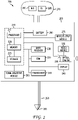
- FIG. 2 shows a high-level block diagram of a further illustrative surveying apparatus 200 configured in accordance with an embodiment where GNSS receiver 230, EDM 235 and optical camera 250 are integrated within image and data processing unit 205.
- GNSS receiver 120 e.g., a high-precision GNSS receiver
- EDM 150 and optical camera 160 are individual components mounted on survey pole 140
- FIG. 2 shows a high-level block diagram of a further illustrative surveying apparatus 200 configured in accordance with an embodiment where GNSS receiver 230, EDM 235 and optical camera 250 are integrated within image and data processing unit 205.
- the accurate measurement of a plurality of remote points is facilitated by integrating a high-precision GNSS receiver, an EDM and an optical camera such that their combined physical location and orientation can be measured and known, and allowing for single calibration thereof.
- this integration may take various forms such as a single, integrated device as shown in FIG. 2 , or individual devices assembled as shown in FIG. 1 .
- surveying apparatus 100 is configured such that GNSS receiver 120, EDM 150 and optical camera 160 are individual components mounted on survey pole 140 having tip end 180.
- image and data processing unit 170 is also a separately mounted device that may include a processor (not shown) for controlling the overall operations of surveying apparatus 100 including but limited to the operations carried out by Measurement Apparatus defined by GNSS receiver 120, EDM 150 and optical camera 160.
- position and sensor orientation unit 110 illustratively includes GNSS receiver 120, IMU 130 (an optional feature) and/or inclination sensor (IS) 185 (an optional feature) which is one of many configurations for GNSS receiver 120 and IMU 130.
- surveying apparatus 100 may now make the further orientation measurements such as slope angles (i.e., a pitch and tilt angle) with respect to a ground surface (i.e., specific measurement position(s) associated with surveying apparatus 100).
- slope angles i.e., a pitch and tilt angle
- a ground surface i.e., specific measurement position(s) associated with surveying apparatus 100.
- integration of GNSS receiver 120, IMU 130, EDM 150 and optical camera 160 may take various forms such as a single, integrated device as shown in FIG. 2 , or individual devices assembled as shown in FIG. 1 , or different combinations of devices (e.g., integration of GNSS receiver 120 with IMU 130 as a single combined device, or integration of optical camera 160 with EDM 150 as single combined device, to name just a few possibilities).
- FIG. 2 shows a high-level block diagram of a further illustrative surveying apparatus 200 configured in accordance with an embodiment where GNSS receiver 230, EDM 235 and optical camera 250 are integrated within image and data processing unit 205 which is mounted to survey pole 260 having tip end 265.
- the Measurement Apparatus defined by GNSS receiver 230, EDM 235 and optical camera 250 is integral to image and data processing unit 205 which further includes processor 215 for controlling the overall operations of image and data processing unit 205, and surveying apparatus 200.
- Processor 215, illustratively part of a computation unit 210 may include both general and special purpose microprocessors, and may be the sole processor or one of multiple processors of image and data processing unit 205.
- Processor 215 may comprise one or more central processing units (CPUs), for example, and may include, be supplemented by, or incorporated in, one or more application-specific integrated circuits (ASICs) and/or one or more field programmable gate arrays (FPGAs).
- CPUs central processing units
- ASICs application-specific integrated circuits
- FPGAs field programmable gate arrays
- Optical camera 250 can be any type of camera, with one camera type preferably having a low distortion lens and high temperature stability, and may have one or more optical sensors, multiple optical elements and/or panoramic capabilities.
- optical camera 250 is a matrix Charge-Coupled Device (CCD) sensor the operation of which is well-known in the art, coupled with a suitable optical lens.
- CCD Charge-Coupled Device
- optical camera 250 is a system of multiple CCD sensors coupled with respective lenses thereby providing a 360 degree or wide-angle image.
- Position and sensor orientation unit 270 illustratively includes IMU 280 and inclination sensor (IS) 285 which is one of many configurations.
- Image and data processing unit 205 further includes video module 255 which may include a video semiconductor chip for providing compressed, digital video (e.g., MPEG-2) data from optical camera 250 to processor 215.
- Transceiver 240 may be any device for transmitting and receiving data over a communications link (e.g., wireless data link) in a conventional manner.
- Communications module 295 may provide a variety of capabilities such as Bluetooth ® communications.
- Input-Output module 275 is a module which includes input means, such as a keypad, touchscreen, haptic controls, voice-recognition means and the like to facilitate user control and interaction with surveying apparatus 200 including but not limited by and through display 245.
- Battery 290 e.g., lithium-ion
- Memory 220 and data storage device 225 may each comprise a tangible non-transitory computer readable storage medium, high-speed random access memory, such as dynamic random access memory (DRAM), static random access memory (SRAM), double data rate synchronous dynamic random access memory (DDR RAM), or other random access solid state memory devices, and may include non-volatile memory, such as one or more magnetic disk storage devices such as internal hard disks and removable disks, magneto-optical disk storage devices, optical disk storage devices, flash memory devices, semiconductor memory devices, such as erasable programmable read-only memory (EPROM), electrically erasable programmable read-only memory (EEPROM), compact disc read-only memory (CD-ROM), digital versatile disc read-only memory (DVD-ROM) disks, or other non-volatile solid state storage devices.
- DRAM dynamic random access memory
- SRAM static random access memory
- DDR RAM double data rate synchronous dynamic random access memory
- non-volatile memory such as one or more magnetic disk storage devices such as internal hard disks and removable
- memory 220 and/or data storage device 225 store various types of information (e.g., image data from optical camera 250, and/or alphanumeric data or other types of data typically utilized by image and data processing unit 205 to carry out the operations of surveying apparatus 200.
- information e.g., image data from optical camera 250, and/or alphanumeric data or other types of data typically utilized by image and data processing unit 205 to carry out the operations of surveying apparatus 200.
- the accurate measurement of a plurality of remote points is facilitated by integrating GNSS receiver 230, EDM 235 and optical camera 250 such that their combined physical location and orientation can be measured and known, and allowing for single calibration thereof.
- Surveying apparatus 200 is used for the surveying and accurate measurement of multiple remote points, associated with a selected target, by using GNSS receiver 230 and EDM 235 to measure one or more remote target points, and simultaneously with these measurements from GNSS receiver 230 and EDM 235 capturing at least two (2) images of the remote target point(s) from optical camera 250.
- FIG. 3 shows a diagram of an illustrative surveying site 300 using surveying apparatus 200, for locating a set of remote target points (i.e., remote target points 330-1, 330-2, 330-3, 330-4, 330-5, 330-6, 330-7, 330-8, 330-9 and 330-N).
- tie point is designated which tie point may be one of the remote target points (e.g., tie point 370-1 or 370-3 associated with building 310), or may be any other point (e.g., tie point 370-2 or 370-N) that is a visually identifiable feature of the selected target and for which an accurate measurement may be made from surveying apparatus 200 (i.e., any point at which EDM 235 may be accurately aimed).
- the remote target points e.g., tie point 370-1 or 370-3 associated with building 310
- tie point e.g., tie point 370-2 or 370-N
- target 320 is selected for which precise measuring is desired (in this example, building 310 is the selected target) and from target 320 the associated set of remote target points are selected, e.g., remote target points 330-1 through 330-7.
- the target 320 is one where the receipt and transmission of GNSS signals are adversely impacted in some fashion.
- At least three (3) measurement locations are selected, i.e., measurement locations 340, 350, and 360, where such locations are not in a straight line (e.g., a serpentine formation) and from which the selected target and the selected target point(s) are visible and can be measured with GNSS receiver 230, as part of surveying apparatus 200 shown at each respective measurement location.
- a straight line e.g., a serpentine formation
- the Measurement Apparatus i.e., GNSS receiver 230, EDM 235, and optical camera 250
- the Measurement Apparatus includes optional sensors (e.g., IMU 280 and/or IS 285)
- IMU 280 and/or IS 285 only two (2) measurement locations need be selected (e.g., measurement location 340 and 360) from which selected target 320 and the selected target point(s) are visible and can be measured with GNSS receiver 230.
- IS 285 e.g., inclinometer
- IMU 280 surveying apparatus 200 may now make the further orientation measurements such as slope angles (i.e., a pitch and tilt angle) with respect to a ground surface (i.e., specific measurement position(s) associated with surveying apparatus 200).
- the position measurements are supplemented with orientation measurements.
- any number of measurements locations can be utilized in either configuration provided that the respective minimum number of measurement location is satisfied.
- building 310 as the selected target 320 it will be understood that the principles described herein are equally applicable to selected target 320-1 which is an area encompassing any number of other points (e.g., remote target points 330-8, 330-9 and 330-N), for example, resident in the vicinity in front of building 310.
- surveying apparatus 200 is positioned at one of the selected measurement locations (e.g., measurement location 340).
- the respective tie point is targeted with EDM 235 (as part of surveying apparatus 200 shown at each respective measurement location), on a simultaneous basis, measurements are taken from EDM 235 and GNSS receiver 230 together with capturing at least one (1) image of target 320 (and remote target points 330-1 through 330-7) from optical camera 250.
- surveying apparatus 200 is positioned at the second one of the selected measurement locations (e.g. measurement location 360).
- the respective tie point is targeted with EDM 235 and on a simultaneous basis measurements are taken from EDM 235 and GNSS receiver 230 together with capturing at least one (1) image of the target 320 (and remote target points 330-1, 330-2, 330-3 and 330-7) from optical camera 250.
- the 3D coordinates for each designated tie point are determined, illustratively using computation unit 210.
- the orientation may be computed by computation unit 210 using any number of well-known techniques such as a three-dimensional Intersection Method.
- the orientation of the Measurement Apparatus i.e., GNSS receiver 230, EDM 235, and optical camera 250 is computed for each measurement location.
- the position and orientation of optical camera 250 at each measurement location is also computed, illustratively using computation unit 210
- This computation is a straightforward geometric computation given that all parts of the Measurement Apparatus (i.e., GNSS receiver 230, EDM 235, and optical camera 250) are mutually calibrated. Initially, using the offset from GNSS receiver 230 (i.e., GNSS antenna phase center) to the EDM (i.e., EDM 235) nodal point (and with respect to which distances are measured), the coordinates of the EDM nodal point from the measured GNSS measurements are derived.
- the orientation of the EDM (e.g., EDM 235) is determined.
- the offset of the camera nodal point e.g., optical camera 250
- the orientation of the camera axis with respect to the EDM axis both being known from prior calibration thereof.
- the coordinates and orientation of the camera nodal point is derived.
- a Least Squares adjustment or similar optimization technique can be utilized to obtain the best approximation of position and orientation.
- the relative positions and orientations of GNSS receiver 230, EDM 235 and optical camera 255 are known. Knowing these orientations, and correcting for any distortions of the respective image(s) using any number of well-known techniques, allows for measuring the coordinates of each remote target point that are visible in the at least 2 images by selecting the respective position of a particular target point on the images and computing the position of the target point using the Intersection Method.
- the Intersection Method is a well-known technique that, in its most basic form, from each of two geo-referenced (i.e., positioned and oriented) images a ray is drawn which corresponds to the pixel position of the target point.
- the Intersection Method will further utilize a Least Squares adjustment or other similar optimization technique to determine the middle point between the multiple rays in space.
- a single set of simultaneous measurements are made (i.e., location/position measurements from GPS receiver 230 and EDM 230, and images from optical camera 250) from which the position of any remote target point can be determined provided such position can be located on at least two images as further detailed below.
- the surveying instrument i.e., surveying apparatus 100 or surveying apparatus 200
- the target point positions are determined with a significant reduction in actual field/site work and without the need to traverse the selected area with the Measurement Apparatus and/or visiting each and every target point within the selected area.
- the disclosed embodiments allow for the reconfiguration of and extension of conventional GNSS surveying equipment for use in areas where GNSS signals are blocked or degraded and eliminate the need for the use of other equipment (e.g., well-known total stations) which can be expensive and further complicate the operations.
- FIG. 4 shows a flowchart of illustrative operations 400 for determining the position of remote target points in accordance with an embodiment.
- the measuring target is selected, and at step 410, a set of remote target points is selected that are associated with the selected measuring target.
- at step 415 at least two (2) measurement locations are selected, and at step 420, at least one tie point is designated.
- the surveying apparatus e.g., surveying apparatus 100 or 200
- the surveying apparatus is positioned at one of the measurement locations.
- any number of measurements locations can be utilized in either configuration provided that the respective minimum number of measurement location is satisfied.
- an EDM (e.g., EDM 150 or EDM 235) is targeted at one of the tie points, and at step 435, measurements from the GNSS receiver (e.g., GNSS receiver 120 or 230) and the EDM (and the IMU, if so configured), and at least one (1) image is captured of the selected measuring area from an optical camera (e.g., optical camera 160 or 250), all on a simultaneous basis.
- a determination, at step 440 is made as to whether there is another designated tie point available and, if so, steps 430 and 435 are repeated. If no further designated tie points are available for measuring, a determination, at step 445, is made as to whether there is another measurement location available and, if so, steps 425 through 440 are repeated for any remaining measurement locations.
- the 3D coordinates of each designated tie point is computed using, illustratively, the Intersection Method at step 450, and the orientation of the surveying apparatus is computed, at step 455, using the coordinates of the respective measurements location and the tie points.
- the position and orientation of the camera at each respective measurement location is computed using the orientation of the surveying apparatus, the position measurements from the GNSS receiver, the orientation measurements from any available IMU, and the known relative positions and orientations of the GNSS receiver, the EDM and the optical camera. Any distortion of the images is corrected, at step 465, and at step 470, the position of at least one of the remote target points is computed as detailed above.
Landscapes
- Engineering & Computer Science (AREA)
- Radar, Positioning & Navigation (AREA)
- Remote Sensing (AREA)
- Physics & Mathematics (AREA)
- General Physics & Mathematics (AREA)
- Computer Networks & Wireless Communication (AREA)
- Multimedia (AREA)
- Length Measuring Devices By Optical Means (AREA)
Claims (14)
- Verfahren (400) zum Bestimmen von Koordinaten mehrerer entfernter Zielpunkte, die einem ausgewählten Ziel in Bezug auf eine Vermessungsvorrichtung (200) zugehörig sind, wobei das Verfahren Folgendes umfasst:Bezeichnen wenigstens eines Verbindungspunkts (420);Verwenden von wenigstens zwei Messorten (415) von mehreren Messorten, die der Vermessungsvorrichtung zugehörig sind, wobei die Vermessungsvorrichtung wenigstens einen Empfänger eines globalen Navigationssatellitensystems (GNSS) (230), einen elektronischen Entfernungsmesser (electronic distance meter - EDM) (235), eine Trägheitsmesseinheit (inertial measurement unit- IMU) (280) und eine optische Kamera (250) umfasst, und:an einem ersten der Messorte, von dem aus die Vermessungsvorrichtung eine Sicht wenigstens des ausgewählten Ziels (435) aufweist,
gleichzeitiges (i) Aufzeichnen erster mehrerer Positions- und Orientierungsmessungen unter Verwendung des GNSS-Empfängers, der IMU und des EDM, einschließlich einer Entfernung zwischen dem Verbindungspunkt und dem ersten Messort, und (ii) Erfassen wenigstens eines ersten Bildes des ausgewählten Ziels unter Verwendung der optischen Kamera (435), wobei der Verbindungspunkt ein visuell identifizierbares Merkmal des ausgewählten Ziels ist und durch den EDM von jedem Messort der mehreren Messorte aus anvisierbar ist;an einem zweiten der Messorte, die der Vermessungsvorrichtung zugehörig sind, vom dem aus die Vermessungsvorrichtung eine Sicht wenigstens des ausgewählten Ziels (445) aufweist,
gleichzeitiges (i) Aufzeichnen zweiter mehrerer Positions- und Orientierungsmessungen unter Verwendung des GNSS-Empfängers, der IMU und des EDM, einschließlich einer Entfernung zwischen dem Verbindungspunkt und dem zweiten Messort, und (ii) Erfassen wenigstens eines zweiten Bildes des ausgewählten Ziels unter Verwendung der optischen Kamera (435);Berechnen eines Satzes von dreidimensionalen (3D) Koordinaten in einem Referenzkoordinatensystem für den Verbindungspunkt unter Verwendung der ersten mehreren Positions- und Orientierungsmessungen und der zweiten mehreren Positions- und Orientierungsmessungen (450);Berechnen einer ersten Orientierung der Vermessungsvorrichtung unter Verwendung der 3D-Koordinaten für den Verbindungspunkt an dem ersten Messort (455);Berechnen einer zweiten Orientierung der Vermessungsvorrichtung unter Verwendung der 3D-Koordinaten für den Verbindungspunkt an dem zweiten Messort (455);Berechnen einer ersten Position und Orientierung der optischen Kamera unter Verwendung der ersten Orientierung der Vermessungsvorrichtung und der ersten mehreren Positions- und Orientierungsmessungen an dem ersten Messort (460);Berechnen einer zweiten Position und Orientierung der optischen Kamera unter Verwendung der zweiten Orientierung der Vermessungsvorrichtung und der zweiten mehreren Positions- und Orientierungsmessungen an dem zweiten Messort (460); undBerechnen eines Satzes von Koordinaten für die mehreren entfernten Zielpunkte unter Verwendung wenigstens des ersten Bildes, des zweiten Bildes, der ersten Position und Orientierung der optischen Kamera und der zweiten Position und Orientierung der optischen Kamera (470). - Verfahren nach Anspruch 1, das ferner Folgendes umfasst:
Korrigieren einer Verzerrung in dem ersten Bild oder dem zweiten Bild (465). - Verfahren nach Anspruch 2, wobei das Berechnen des Satzes von Koordinaten für die mehreren entfernten Zielpunkte ferner Folgendes umfasst:
Orten wenigstens eines entfernten Zielpunkts auf dem ersten Bild und dem zweiten Bild. - Verfahren nach Anspruch 3, wobei das Korrigieren der Verzerrung mehrere Kalibrierungsparameter verwendet, die der optischen Kamera zugehörig sind.
- Verfahren nach Anspruch 1, wobei die optische Kamera eine Sensorkamera ist.
- Verfahren nach Anspruch 1, wobei der GNSS-Empfänger, der EDM, die IMU und die optische Kamera jeweils getrennte Einheiten sind, die an einem Vermessungsstab der Vermessungsvorrichtung wirkverknüpft sind.
- Vermessungsvorrichtung zum Bestimmen von Koordinaten mehrerer entfernter Zielpunkte, die einem ausgewählten Ziel in Bezug auf die Vermessungsvorrichtung zugehörig sind, wobei die Vermessungsvorrichtung Folgendes umfasst:einen Vermessungsstab, der einen GNSS-Empfänger, einen elektronischen Entfernungsmesser (EDM), eine Trägheits messeinheit (IMU) und eine optische Kamera, die damit wirkverknüpft ist, aufweist;einen Prozessor;einen Speicher, der mit dem Prozessor gekoppelt ist, wobei der Speicher Computerprogrammanweisungen speichert, die, wenn sie ausgeführt werden, den Prozessor veranlassen, Abläufe für Folgendes durchzuführen:Aufnehmen einer Bezeichnung von wenigstens einer Verbindungsstelle;Verwenden von wenigstens zwei Messorten von mehreren Messorten, die der Vermessungsvorrichtung zugehörig sind:Aufnehmen, hinsichtlich eines ersten der Messorte, erster mehrerer Positions- und Orientierungsmessungen und eines ersten Bildes des ausgewählten Ziels, wobei die ersten mehreren Messungen und das erste Bild, hinsichtlich der ersten mehreren Positions- und Orientierungsmessungen, von dem GNSS-Empfänger, der IMU und dem EDM gleichzeitig (i) aufgezeichnet wurden, einschließlich einer Entfernung zwischen dem Verbindungspunkt und dem ersten Messort, und, hinsichtlich des ersten Bildes des ausgewähltes Ziels, von der optischen Kamera (ii) erfasst wurden, wobei der Verbindungspunkt ein visuell identifizierbares Merkmal des ausgewählten Ziels ist und durch den EDM von jedem der Messorte der mehreren Messorte aus anvisierbar ist;Aufnehmen, hinsichtlich eines zweiten der Messorte, zweiter mehrerer Positions- und Orientierungsmessungen und eines zweiten Bildes des ausgewählten Ziels, wobei die zweiten mehreren Messungen und das zweite Bild, mittels der zweiten mehreren Positions- und Orientierungsmessungen, von dem GNSS-Empfänger, der IMU und dem EDM gleichzeitig (i) aufgezeichnet wurden, einschließlich einer Entfernung zwischen dem Verbindungspunkt und dem zweiten Messort, und, mittels des zweiten Bildes des ausgewählten Ziels, von der optischen Kamera (ii) erfasst wurden;Berechnen eines Satzes von dreidimensionalen (3D) Koordinaten in einem Referenzkoordinatensystem für den Verbindungspunkt unter Verwendung der ersten mehreren Positions- und Orientierungsmessungen und der zweiten mehreren Positions- und Orientierungsmessungen;Berechnen einer ersten Orientierung der Vermessungsvorrichtung unter Verwendung der 3D-Koordinaten für den Verbindungspunkt an dem ersten Messort;Berechnen einer zweiten Orientierung der Vermessungsvorrichtung unter Verwendung der 3D-Koordinaten für den Verbindungspunkt an dem zweiten Messort;Berechnen einer ersten Position und Orientierung der optischen Kamera unter Verwendung der ersten Orientierung der Vermessungsvorrichtung und der ersten mehreren Positions- und Orientierungsmessungen an dem ersten Messort;Berechnen einer zweiten Position und Orientierung der optischen Kamera unter Verwendung der zweiten Orientierung der Vermessungsvorrichtung und der zweiten mehreren Positions- und Orientierungsmessungen an dem zweiten Messort; undBerechnen eines Satzes von Koordinaten für die mehreren entfernten Zielpunkte unter Verwendung wenigstens des ersten Bildes, des zweiten Bildes, der ersten Position und Orientierung der optischen Kamera und der zweiten Position und Orientierung der optischen Kamera.
- Vermessungsvorrichtung nach Anspruch 7, wobei der Vermessungsstab derart positioniert ist, dass das ausgewählte Ziel für die optische Kamera sichtbar ist.
- Vermessungsvorrichtung nach Anspruch 7, wobei jegliche Verzerrung in dem ersten Bild und dem zweiten Bild korrigiert wird.
- Vermessungsvorrichtung nach Anspruch 9, wobei der bezeichnete Verbindungspunkt einer der entfernten Zielpunkte ist.
- Vermessungsvorrichtung nach Anspruch 10, wobei der GNSS-Empfänger, der EDM, die IMU und die optische Kamera jeweils getrennte Einheiten sind, die an dem Vermessungsstab wirkverknüpft sind.
- Nicht flüchtiges computerlesbares Medium, das Computerprogrammanweisungen zum Bestimmen von Koordinaten mehrerer entfernter Zielpunkte speichert, die einem ausgewählten Ziel unter Verwendung einer Vermessungsvorrichtung zugehörig sind, wobei die Vermessungsvorrichtung einen Vermessungsstab aufweist, der einen GNSS-Empfänger, einen EDM, eine Trägheitsmesseinheit (IMU) und eine optische Kamera, die damit wirkverknüpft ist, aufweist, wobei die Computerprogrammanweisungen, wenn sie auf einem Prozessor ausgeführt werden, den Prozessor veranlassen, Abläufe durchzuführen, die Folgendes umfassen:Aufnehmen einer Bezeichnung von wenigstens einer Verbindungsstelle;Verwenden von wenigstens zwei Messorten von mehreren Messorten, die der Vermessungsvorrichtung zugehörig sind, und:Aufnehmen, hinsichtlich eines ersten der Messorte, erster mehrerer Positions- und Orientierungsmessungen und eines ersten Bildes des ausgewählten Ziels, wobei die ersten mehreren Messungen und das erste Bild, mittels der ersten mehreren Positions- und Orientierungsmessungen, von dem GNSS-Empfänger, der IMU und dem EDM gleichzeitig (i) aufgezeichnet wurden, einschließlich einer Entfernung zwischen dem Verbindungspunkt und dem ersten Messort, und, mittels des ersten Bildes des ausgewähltes Ziels, von der optischen Kamera (ii) erfasst wurden, wobei der Verbindungspunkt ein visuell identifizierbares Merkmal des ausgewählten Ziels ist und durch den EDM von jedem der Messorte der mehreren Messorte aus anvisierbar ist;Aufnehmen, hinsichtlich eines zweiten der Messorte, zweiter mehrerer Positions- und Orientierungsmessungen und eines zweiten Bildes des ausgewählten Ziels, wobei die zweiten mehreren Messungen und das zweite Bild, mittels der zweiten mehreren Positions- und Orientierungsmessungen, von dem GNSS-Empfänger, der IMU und dem EDM gleichzeitig (i) aufgezeichnet wurden, einschließlich einer Entfernung zwischen dem Verbindungspunkt und dem zweiten Messort, und, mittels des zweiten Bildes des ausgewählten Ziels, von der optischen Kamera (ii) erfasst wurden;Berechnen eines Satzes von dreidimensionalen (3D) Koordinaten in einem Referenzkoordinatensystem für den Verbindungspunkt unter Verwendung der ersten mehreren Positions- und Orientierungsmessungen und der zweiten mehreren Positions- und Orientierungsmessungen;Berechnen einer ersten Orientierung der Vermessungsvorrichtung unter Verwendung der 3D-Koordinaten für den Verbindungspunkt an dem ersten Messort;Berechnen einer zweiten Orientierung der Vermessungsvorrichtung unter Verwendung der 3D-Koordinaten für den Verbindungspunkt an dem zweiten Messort;Berechnen einer ersten Position und Orientierung der optischen Kamera unter Verwendung der ersten Orientierung der Vermessungsvorrichtung und der ersten mehreren Positions- und Orientierungsmessungen an dem ersten Messort;Berechnen einer zweiten Position und Orientierung der optischen Kamera unter Verwendung der zweiten Orientierung der Vermessungsvorrichtung und der zweiten mehreren Positions- und Orientierungsmessungen an dem zweiten Messort; undBerechnen eines Satzes von Koordinaten für die mehreren entfernten Zielpunkte unter Verwendung wenigstens des ersten Bildes, des zweiten Bildes, der ersten Position und Orientierung der optischen Kamera und der zweiten Position und Orientierung der optischen Kamera.
- Verfahren zum Bestimmen von Koordinaten mehrerer entfernter Zielpunkte, die einem ausgewählten Ziel in Bezug auf eine Vermessungsvorrichtung zugehörig sind, wobei das Verfahren Folgendes umfasst:Bezeichnen wenigstens eines Verbindungspunkts;Verwenden von wenigstens drei Messorten von mehreren Messorten, die der Vermessungsvorrichtung zugehörig sind, wobei die Vermessungsvorrichtung wenigstens einen Empfänger eines globalen Navigationssatellitensystems (GNSS), einen elektronischen Entfernungsmesser (EDM) und eine optische Kamera umfasst, und:an einem ersten der Messorte, von dem aus die Vermessungsvorrichtung eine Sicht wenigstens des ausgewählten Ziels aufweist,
gleichzeitiges (i) Aufzeichnen erster mehrerer Positionsmessungen von dem GNSS-Empfänger und dem EDM, einschließlich einer Entfernung zwischen dem Verbindungspunkt und dem ersten Messort, und (ii) Erfassen wenigstens eines ersten Bildes des ausgewählten Ziels, wobei der Verbindungspunkt ein visuell identifizierbares Merkmal des ausgewählten Ziels ist und durch den EDM von jedem der Messorte der mehreren Messorte aus anvisierbar ist;an einem zweiten der Messorte, die der Vermessungsvorrichtung zugehörig sind, vom dem aus die Vermessungsvorrichtung eine Sicht wenigstens des ausgewählten Ziels aufweist,gleichzeitiges (i) Aufzeichnen zweiter mehrerer Positionsmessungen von dem GNSS-Empfänger und dem EDM, einschließlich einer Entfernung zwischen dem Verbindungspunkt und dem zweiten Messort, und (ii) Erfassen wenigstens eines zweiten Bildes des ausgewählten Ziels;an einem dritten der Messorte, von dem aus die Vermessungsvorrichtung eine Sicht wenigstens des ausgewählten Ziels aufweist,
gleichzeitiges (i) Aufzeichnen dritter mehrerer Positionsmessungen von dem GNSS-Empfänger und dem EDM, einschließlich einer Entfernung zwischen dem Verbindungspunkt und dem dritten Messort, und (ii) Erfassen eines dritten Bildes des ausgewählten Ziels;Berechnen eines Satzes von dreidimensionalen (3D) Koordinaten in einem Referenzkoordinatensystem für den Verbindungspunkt unter Verwendung der ersten mehreren Positionsmessungen, der zweiten mehreren Positionsmessungen und der dritten mehreren Messungen;Berechnen einer ersten Orientierung der Vermessungsvorrichtung unter Verwendung der 3D-Koordinaten für den Verbindungspunkt an dem ersten Messort;Berechnen einer zweiten Orientierung der Vermessungsvorrichtung unter Verwendung der 3D-Koordinaten für den Verbindungspunkt an dem zweiten Messort;Berechnen einer dritten Orientierung der Vermessungsvorrichtung unter Verwendung der 3D-Koordinaten für den Verbindungspunkt an dem dritten Messort;Berechnen einer ersten Position und Orientierung der optischen Kamera unter Verwendung der ersten Orientierung der Vermessungsvorrichtung und der ersten mehreren Positionsmessungen an dem ersten Messort;Berechnen einer zweiten Position und Orientierung der optischen Kamera unter Verwendung der zweiten Orientierung der Vermessungsvorrichtung und der zweiten mehreren Positionsmessungen an dem zweiten Messort;Berechnen einer dritten Position und Orientierung der optischen Kamera unter Verwendung der dritten Orientierung der Vermessungsvorrichtung und der dritten mehreren Positionsmessungen an dem dritten Messort; undBerechnen eines Satzes von Koordinaten für die mehreren entfernten Zielpunkte unter Verwendung wenigstens des ersten Bildes, des zweiten Bildes, des dritten Bildes, der ersten Position und Orientierung der optischen Kamera und der zweiten Position und Orientierung der optischen Kamera, und der dritten Position und Orientierung der optischen Kamera. - Vermessungsvorrichtung zum Bestimmen von Koordinaten mehrerer entfernter Zielpunkte, die einem ausgewählten Ziel in Bezug auf die Vermessungsvorrichtung zugehörig sind, wobei die Vermessungsvorrichtung Folgendes umfasst:einen Vermessungsstab, der einen GNS-Empfänger, einen EDM und eine optische Kamera, die damit wirkverknüpft ist, aufweist;einen Prozessor;einen Speicher, der mit dem Prozessor gekoppelt ist, wobei der Speicher Computerprogrammanweisungen speichert, die, wenn sie ausgeführt werden, den Prozessor veranlassen, Abläufe für Folgendes durchzuführen:Aufnehmen einer Bezeichnung von wenigstens einer Verbindungsstelle;Verwenden von wenigstens drei Messorten von mehreren Messorten, die der Vermessungsvorrichtung zugehörig sind:Aufnehmen, hinsichtlich eines ersten der Messorte, erster mehrerer Positionsmessungen und eines ersten Bildes des ausgewählten Ziels, wobei die ersten mehreren Messungen und das erste Bild, hinsichtlich der ersten mehreren Positionsmessungen, von dem GNSS-Empfänger und dem EDM gleichzeitig (i) aufgezeichnet wurden, einschließlich einer Entfernung zwischen dem Verbindungspunkt und dem ersten Messort, und hinsichtlich des ersten Bildes des ausgewähltes Ziels, von der optischen Kamera (ii) erfasst wurden, wobei der Verbindungspunkt ein visuell identifizierbares Merkmal des ausgewählten Ziels ist und durch den EDM von jedem der Messorte der mehreren Messorte aus anvisierbar ist;Aufnehmen, hinsichtlich eines zweiten der Messorte, zweiter mehrerer Positionsmessungen und eines zweiten Bildes des ausgewählten Ziels, wobei die zweiten mehreren Messungen und das zweite Bild, mittels der zweiten mehreren Positionsmessungen, von dem GNSS-Empfänger und dem EDM gleichzeitig (i) aufgezeichnet wurden, einschließlich einer Entfernung zwischen dem Verbindungspunkt und dem zweiten Messort, und, mittels des zweiten Bildes des ausgewählten Ziels, von der optischen Kamera (ii) erfasst wurden;Aufnehmen, hinsichtlich eines dritten der Messorte, dritter mehrerer Positionsmessungen und eines dritten Bildes des ausgewählten Ziels, wobei die dritten mehreren Messungen und das dritte Bild, mittels der dritten mehreren Positionsmessungen, von dem GNSS-Empfänger und dem EDM gleichzeitig (i) aufgezeichnet wurden, einschließlich einer Entfernung zwischen dem Verbindungspunkt und dem dritten Messort, und, mittels des dritten Bildes des ausgewählten Ziels, von der optischen Kamera (ii) erfasst wurden;Berechnen eines Satzes von dreidimensionalen (3D) Koordinaten in einem Referenzkoordinatensystem für den Verbindungspunkt unter Verwendung der ersten mehreren Positionsmessungen, der zweiten mehreren Positionsmessungen und der dritten mehreren Positionsmessungen;Berechnen einer ersten Orientierung der Vermessungsvorrichtung unter Verwendung der 3D-Koordinaten für den Verbindungspunkt an dem ersten Messort;Berechnen einer zweiten Orientierung der Vermessungsvorrichtung unter Verwendung der 3D-Koordinaten für den Verbindungspunkt an dem zweiten Messort;Berechnen einer dritten Orientierung der Vermessungsvorrichtung unter Verwendung der 3D-Koordinaten für den Verbindungspunkt an dem dritten Messort;Berechnen einer ersten Position und Orientierung der optischen Kamera unter Verwendung der ersten Orientierung der Vermessungsvorrichtung und der ersten mehreren Positionsmessungen an dem ersten Messort;Berechnen einer zweiten Position und Orientierung der optischen Kamera unter Verwendung der zweiten Orientierung der Vermessungsvorrichtung und der zweiten mehreren Positionsmessungen an dem zweiten Messort;Berechnen einer dritten Position und Orientierung der optischen Kamera unter Verwendung der dritten Orientierung der Vermessungsvorrichtung und der dritten mehreren Positionsmessungen an dem dritten Messort; undBerechnen eines Satzes von Koordinaten für die mehreren entfernten Zielpunkte unter Verwendung wenigstens des ersten Bildes, des zweiten Bildes, des dritten Bildes, der ersten Position und Orientierung der optischen Kamera und der zweiten Position und Orientierung der optischen Kamera, und der dritten Position und Orientierung der optischen Kamera.
Applications Claiming Priority (2)
| Application Number | Priority Date | Filing Date | Title |
|---|---|---|---|
| US15/389,877 US10563980B2 (en) | 2016-12-23 | 2016-12-23 | Enhanced remote surveying systems and methods |
| PCT/US2017/061637 WO2018118277A1 (en) | 2016-12-23 | 2017-11-14 | Enhanced remote surveying systems and methods |
Publications (2)
| Publication Number | Publication Date |
|---|---|
| EP3559596A1 EP3559596A1 (de) | 2019-10-30 |
| EP3559596B1 true EP3559596B1 (de) | 2022-04-13 |
Family
ID=60570230
Family Applications (1)
| Application Number | Title | Priority Date | Filing Date |
|---|---|---|---|
| EP17808686.4A Active EP3559596B1 (de) | 2016-12-23 | 2017-11-14 | Systeme und verfahren zur verbesserte fernüberwachung |
Country Status (3)
| Country | Link |
|---|---|
| US (1) | US10563980B2 (de) |
| EP (1) | EP3559596B1 (de) |
| WO (1) | WO2018118277A1 (de) |
Families Citing this family (28)
| Publication number | Priority date | Publication date | Assignee | Title |
|---|---|---|---|---|
| EP3182066B1 (de) * | 2015-12-17 | 2018-07-04 | Leica Geosystems AG | Vermessungsstab |
| JP7061119B2 (ja) | 2016-07-15 | 2022-04-27 | ファストブリック・アイピー・プロプライエタリー・リミテッド | 車両に組み込まれた煉瓦/ブロック敷設機 |
| ES2899585T3 (es) | 2016-07-15 | 2022-03-14 | Fastbrick Ip Pty Ltd | Pluma para transporte de material |
| US10581160B2 (en) | 2016-12-16 | 2020-03-03 | Gopro, Inc. | Rotational wireless communication system |
| US10816676B2 (en) * | 2017-02-25 | 2020-10-27 | Uti Limited Partnership | GNSS/INS integration deep inside of inertial sensors |
| US20180276470A1 (en) * | 2017-03-23 | 2018-09-27 | Rohde & Schwarz Gmbh & Co. Kg | Measuring system and method for displaying a live view of a measurement setup superimposed on measurement results |
| CN111095355B (zh) | 2017-07-05 | 2023-10-20 | 快砖知识产权私人有限公司 | 实时定位和定向跟踪器 |
| US11958193B2 (en) | 2017-08-17 | 2024-04-16 | Fastbrick Ip Pty Ltd | Communication system for an interaction system |
| AU2018317941B2 (en) | 2017-08-17 | 2023-11-09 | Fastbrick Ip Pty Ltd | Laser tracker with improved roll angle measurement |
| CN111212799B (zh) | 2017-10-11 | 2023-04-14 | 快砖知识产权私人有限公司 | 用于传送物体的机器以及与其一起使用的多隔间转盘 |
| WO2020014737A1 (en) | 2018-07-16 | 2020-01-23 | Fastbrick Ip Pty Ltd | Backup tracking for an interaction system |
| US12311546B2 (en) | 2018-07-16 | 2025-05-27 | Fastbrick Ip Pty Ltd | Active damping system |
| EP3598176B1 (de) * | 2018-07-20 | 2024-10-02 | Trimble Inc. | Verfahren zur georäumlichen positionierung und tragbare positionierungsvorrichtungen dafür |
| JP7183017B2 (ja) * | 2018-12-11 | 2022-12-05 | 株式会社トプコン | 測量装置及び写真測量方法 |
| US11727646B2 (en) * | 2019-04-10 | 2023-08-15 | Trimble Inc. | Augmented reality image occlusion |
| CN110017849B (zh) * | 2019-04-18 | 2020-12-22 | 菲曼(北京)科技有限公司 | 一种基于gnss接收机和imu传感器的测绘一体机的倾斜测量方法 |
| CN114829874B (zh) * | 2019-07-31 | 2024-09-06 | 虚拟线上有限公司 | 沿区域中路径来对齐物品的系统 |
| WO2021075967A1 (en) * | 2019-10-18 | 2021-04-22 | Xnr B.V. | Method and apparatus for optical measurement of environments |
| US11536857B2 (en) * | 2019-12-19 | 2022-12-27 | Trimble Inc. | Surface tracking on a survey pole |
| US11175134B2 (en) * | 2019-12-19 | 2021-11-16 | Trimble Inc. | Surface tracking with multiple cameras on a pole |
| CN115443363A (zh) | 2020-04-22 | 2022-12-06 | 快砖知识产权私人有限公司 | 块传送装置及用于与其一起使用的改进的夹紧组件 |
| CN115698767A (zh) * | 2020-05-05 | 2023-02-03 | 伊莱·艾特克斯家族有限公司 | 土地测量的方法与系统 |
| CN111486781A (zh) * | 2020-05-29 | 2020-08-04 | 桂林电子科技大学 | 一种基于gnss技术的深层位移监测装置及方法 |
| AU2021304545B2 (en) | 2020-07-08 | 2025-12-04 | Fastbrick Ip Pty Ltd | Adhesive application system |
| EP4012335B1 (de) | 2020-12-11 | 2025-04-30 | Leica Geosystems AG | Verfahren zur entfernungsfehlerkorrektur |
| SE544823C2 (en) * | 2021-04-15 | 2022-12-06 | Saab Ab | A method, software product, and system for determining a position and orientation in a 3D reconstruction of the Earth´s surface |
| KR102475087B1 (ko) * | 2022-05-02 | 2022-12-07 | 주식회사 우리강산시스템 | 사용 편의성이 향상된 gnss 기반 기준점 측량장치 |
| US20240191992A1 (en) * | 2022-11-02 | 2024-06-13 | David G. Amendola | Geodetic surveying system and method of operation |
Family Cites Families (21)
| Publication number | Priority date | Publication date | Assignee | Title |
|---|---|---|---|---|
| US5739785A (en) | 1993-03-04 | 1998-04-14 | Trimble Navigation Limited | Location and generation of high accuracy survey control marks using satellites |
| US5512905A (en) * | 1994-10-27 | 1996-04-30 | Trimble Navigation Limited | Pole-tilt sensor for surveyor range pole |
| US6163294A (en) | 1998-09-10 | 2000-12-19 | Trimble Navigation Limited | Time-tagging electronic distance measurement instrument measurements to serve as legal evidence of calibration |
| EP1681533A1 (de) * | 2005-01-14 | 2006-07-19 | Leica Geosystems AG | Verfahren und geodätisches Gerät zur Vermessung wenigstens eines Zieles |
| US7541974B2 (en) | 2005-12-15 | 2009-06-02 | Trimble Navigation Limited | Managed traverse system and method to acquire accurate survey data in absence of precise GPS data |
| US8422767B2 (en) | 2007-04-23 | 2013-04-16 | Gabor Ligeti | Method and apparatus for transforming signal data |
| US8897482B2 (en) | 2008-02-29 | 2014-11-25 | Trimble Ab | Stereo photogrammetry from a single station using a surveying instrument with an eccentric camera |
| US7991575B2 (en) | 2009-01-08 | 2011-08-02 | Trimble Navigation Limited | Method and system for measuring angles based on 360 degree images |
| WO2011163454A1 (en) * | 2010-06-25 | 2011-12-29 | Trimble Navigation Ltd. | Method and apparatus for image-based positioning |
| EP2405236B1 (de) * | 2010-07-07 | 2012-10-31 | Leica Geosystems AG | Geodätisches Vermessungsgerät mit automatischer hochpräziser Zielpunkt-Anzielfunktionalität |
| EP2431708A1 (de) * | 2010-09-16 | 2012-03-21 | Leica Geosystems AG | Geodätisches Vermessungssystem mit in einer Fernbedieneinheit integrierter Kamera |
| US9182229B2 (en) * | 2010-12-23 | 2015-11-10 | Trimble Navigation Limited | Enhanced position measurement systems and methods |
| US10168153B2 (en) * | 2010-12-23 | 2019-01-01 | Trimble Inc. | Enhanced position measurement systems and methods |
| US9562764B2 (en) * | 2012-07-23 | 2017-02-07 | Trimble Inc. | Use of a sky polarization sensor for absolute orientation determination in position determining systems |
| US9513120B2 (en) * | 2012-09-20 | 2016-12-06 | Trimble Navigation Limited | Workflow improvements for stakeout |
| EP2722647A1 (de) * | 2012-10-18 | 2014-04-23 | Leica Geosystems AG | Überwachungssystem und Verfahren |
| US9367962B2 (en) * | 2013-10-22 | 2016-06-14 | Topcon Positioning Systems, Inc. | Augmented image display using a camera and a position and orientation sensor |
| EP3333541A3 (de) * | 2014-05-05 | 2019-07-03 | Hexagon Technology Center GmbH | Vermessungssystem |
| WO2015187993A1 (en) * | 2014-06-06 | 2015-12-10 | Carlson Software Inc. | Gnss mobile base station and data collector with electronic leveling |
| EP3021078B1 (de) * | 2014-11-14 | 2018-09-26 | Leica Geosystems AG | Geodätisches Erfassungssystem mit virtuellen Kamera |
| EP3086283B1 (de) * | 2015-04-21 | 2019-01-16 | Hexagon Technology Center GmbH | Bereitstellung einer point-cloud unter verwendung eines vermessungsinstruments und einer kameravorrichtung |
-
2016
- 2016-12-23 US US15/389,877 patent/US10563980B2/en active Active
-
2017
- 2017-11-14 EP EP17808686.4A patent/EP3559596B1/de active Active
- 2017-11-14 WO PCT/US2017/061637 patent/WO2018118277A1/en not_active Ceased
Non-Patent Citations (1)
| Title |
|---|
| None * |
Also Published As
| Publication number | Publication date |
|---|---|
| US20180180416A1 (en) | 2018-06-28 |
| US10563980B2 (en) | 2020-02-18 |
| EP3559596A1 (de) | 2019-10-30 |
| WO2018118277A1 (en) | 2018-06-28 |
Similar Documents
| Publication | Publication Date | Title |
|---|---|---|
| EP3559596B1 (de) | Systeme und verfahren zur verbesserte fernüberwachung | |
| US10338228B2 (en) | Portable GNSS survey system | |
| US9562764B2 (en) | Use of a sky polarization sensor for absolute orientation determination in position determining systems | |
| US8897482B2 (en) | Stereo photogrammetry from a single station using a surveying instrument with an eccentric camera | |
| CN110737007B (zh) | 用于获得地理空间位置的便携式定位设备和方法 | |
| CA2925850C (en) | Target direction determination method and system | |
| US11796682B2 (en) | Methods for geospatial positioning and portable positioning devices thereof | |
| US20210190969A1 (en) | Surface tracking on a survey pole | |
| US11922653B2 (en) | Locating system | |
| CN105783875A (zh) | 一种集成非扫描激光雷达的航空摄影测量系统及方法 | |
| CN105300362A (zh) | 一种应用于rtk接收机的摄影测量方法 | |
| US10337863B2 (en) | Survey system | |
| US10184799B2 (en) | Systems and methods for targeting objects of interest in denied GPS environments | |
| US11175134B2 (en) | Surface tracking with multiple cameras on a pole | |
| KR100963680B1 (ko) | 원격 표적의 좌표 측정 장치 및 방법 | |
| Pelc-Mieczkowska et al. | Comparison of selected data acquisition methods for GNSS terrain obstacles modeling | |
| Deltsidis et al. | Orthorectification of World View 2 stereo pair using a new rigorous orientation model | |
| Cao et al. | Geometric calibration of Ziyuan-3 three-line cameras using ground control lines | |
| CN205593524U (zh) | 一种集成非扫描激光雷达的航空摄影测量系统 | |
| WO2016151574A1 (en) | Celestial compass and methods of use and calibration | |
| WO2021127570A1 (en) | Surface tracking with multiple cameras on a pole | |
| Yilmaz et al. | Did satellite imagery supersede aerial imagery? A perspective from 3D geopositioning accuracy | |
| Hassan et al. | System Calibration of Land-Based Mobile Mapping Systems |
Legal Events
| Date | Code | Title | Description |
|---|---|---|---|
| STAA | Information on the status of an ep patent application or granted ep patent |
Free format text: STATUS: UNKNOWN |
|
| STAA | Information on the status of an ep patent application or granted ep patent |
Free format text: STATUS: THE INTERNATIONAL PUBLICATION HAS BEEN MADE |
|
| PUAI | Public reference made under article 153(3) epc to a published international application that has entered the european phase |
Free format text: ORIGINAL CODE: 0009012 |
|
| STAA | Information on the status of an ep patent application or granted ep patent |
Free format text: STATUS: REQUEST FOR EXAMINATION WAS MADE |
|
| 17P | Request for examination filed |
Effective date: 20190701 |
|
| AK | Designated contracting states |
Kind code of ref document: A1 Designated state(s): AL AT BE BG CH CY CZ DE DK EE ES FI FR GB GR HR HU IE IS IT LI LT LU LV MC MK MT NL NO PL PT RO RS SE SI SK SM TR |
|
| AX | Request for extension of the european patent |
Extension state: BA ME |
|
| DAV | Request for validation of the european patent (deleted) | ||
| DAX | Request for extension of the european patent (deleted) | ||
| STAA | Information on the status of an ep patent application or granted ep patent |
Free format text: STATUS: EXAMINATION IS IN PROGRESS |
|
| 17Q | First examination report despatched |
Effective date: 20200805 |
|
| GRAP | Despatch of communication of intention to grant a patent |
Free format text: ORIGINAL CODE: EPIDOSNIGR1 |
|
| STAA | Information on the status of an ep patent application or granted ep patent |
Free format text: STATUS: GRANT OF PATENT IS INTENDED |
|
| INTG | Intention to grant announced |
Effective date: 20211130 |
|
| GRAJ | Information related to disapproval of communication of intention to grant by the applicant or resumption of examination proceedings by the epo deleted |
Free format text: ORIGINAL CODE: EPIDOSDIGR1 |
|
| STAA | Information on the status of an ep patent application or granted ep patent |
Free format text: STATUS: EXAMINATION IS IN PROGRESS |
|
| GRAP | Despatch of communication of intention to grant a patent |
Free format text: ORIGINAL CODE: EPIDOSNIGR1 |
|
| STAA | Information on the status of an ep patent application or granted ep patent |
Free format text: STATUS: GRANT OF PATENT IS INTENDED |
|
| INTC | Intention to grant announced (deleted) | ||
| GRAS | Grant fee paid |
Free format text: ORIGINAL CODE: EPIDOSNIGR3 |
|
| GRAA | (expected) grant |
Free format text: ORIGINAL CODE: 0009210 |
|
| STAA | Information on the status of an ep patent application or granted ep patent |
Free format text: STATUS: THE PATENT HAS BEEN GRANTED |
|
| INTG | Intention to grant announced |
Effective date: 20220216 |
|
| AK | Designated contracting states |
Kind code of ref document: B1 Designated state(s): AL AT BE BG CH CY CZ DE DK EE ES FI FR GB GR HR HU IE IS IT LI LT LU LV MC MK MT NL NO PL PT RO RS SE SI SK SM TR |
|
| REG | Reference to a national code |
Ref country code: GB Ref legal event code: FG4D |
|
| REG | Reference to a national code |
Ref country code: CH Ref legal event code: EP |
|
| REG | Reference to a national code |
Ref country code: DE Ref legal event code: R096 Ref document number: 602017055997 Country of ref document: DE |
|
| REG | Reference to a national code |
Ref country code: IE Ref legal event code: FG4D |
|
| REG | Reference to a national code |
Ref country code: AT Ref legal event code: REF Ref document number: 1483733 Country of ref document: AT Kind code of ref document: T Effective date: 20220515 |
|
| REG | Reference to a national code |
Ref country code: LT Ref legal event code: MG9D |
|
| REG | Reference to a national code |
Ref country code: NL Ref legal event code: MP Effective date: 20220413 |
|
| REG | Reference to a national code |
Ref country code: AT Ref legal event code: MK05 Ref document number: 1483733 Country of ref document: AT Kind code of ref document: T Effective date: 20220413 |
|
| PG25 | Lapsed in a contracting state [announced via postgrant information from national office to epo] |
Ref country code: NL Free format text: LAPSE BECAUSE OF FAILURE TO SUBMIT A TRANSLATION OF THE DESCRIPTION OR TO PAY THE FEE WITHIN THE PRESCRIBED TIME-LIMIT Effective date: 20220413 |
|
| PG25 | Lapsed in a contracting state [announced via postgrant information from national office to epo] |
Ref country code: SE Free format text: LAPSE BECAUSE OF FAILURE TO SUBMIT A TRANSLATION OF THE DESCRIPTION OR TO PAY THE FEE WITHIN THE PRESCRIBED TIME-LIMIT Effective date: 20220413 Ref country code: PT Free format text: LAPSE BECAUSE OF FAILURE TO SUBMIT A TRANSLATION OF THE DESCRIPTION OR TO PAY THE FEE WITHIN THE PRESCRIBED TIME-LIMIT Effective date: 20220816 Ref country code: NO Free format text: LAPSE BECAUSE OF FAILURE TO SUBMIT A TRANSLATION OF THE DESCRIPTION OR TO PAY THE FEE WITHIN THE PRESCRIBED TIME-LIMIT Effective date: 20220713 Ref country code: LT Free format text: LAPSE BECAUSE OF FAILURE TO SUBMIT A TRANSLATION OF THE DESCRIPTION OR TO PAY THE FEE WITHIN THE PRESCRIBED TIME-LIMIT Effective date: 20220413 Ref country code: HR Free format text: LAPSE BECAUSE OF FAILURE TO SUBMIT A TRANSLATION OF THE DESCRIPTION OR TO PAY THE FEE WITHIN THE PRESCRIBED TIME-LIMIT Effective date: 20220413 Ref country code: GR Free format text: LAPSE BECAUSE OF FAILURE TO SUBMIT A TRANSLATION OF THE DESCRIPTION OR TO PAY THE FEE WITHIN THE PRESCRIBED TIME-LIMIT Effective date: 20220714 Ref country code: FI Free format text: LAPSE BECAUSE OF FAILURE TO SUBMIT A TRANSLATION OF THE DESCRIPTION OR TO PAY THE FEE WITHIN THE PRESCRIBED TIME-LIMIT Effective date: 20220413 Ref country code: ES Free format text: LAPSE BECAUSE OF FAILURE TO SUBMIT A TRANSLATION OF THE DESCRIPTION OR TO PAY THE FEE WITHIN THE PRESCRIBED TIME-LIMIT Effective date: 20220413 Ref country code: BG Free format text: LAPSE BECAUSE OF FAILURE TO SUBMIT A TRANSLATION OF THE DESCRIPTION OR TO PAY THE FEE WITHIN THE PRESCRIBED TIME-LIMIT Effective date: 20220713 Ref country code: AT Free format text: LAPSE BECAUSE OF FAILURE TO SUBMIT A TRANSLATION OF THE DESCRIPTION OR TO PAY THE FEE WITHIN THE PRESCRIBED TIME-LIMIT Effective date: 20220413 |
|
| PG25 | Lapsed in a contracting state [announced via postgrant information from national office to epo] |
Ref country code: RS Free format text: LAPSE BECAUSE OF FAILURE TO SUBMIT A TRANSLATION OF THE DESCRIPTION OR TO PAY THE FEE WITHIN THE PRESCRIBED TIME-LIMIT Effective date: 20220413 Ref country code: PL Free format text: LAPSE BECAUSE OF FAILURE TO SUBMIT A TRANSLATION OF THE DESCRIPTION OR TO PAY THE FEE WITHIN THE PRESCRIBED TIME-LIMIT Effective date: 20220413 Ref country code: LV Free format text: LAPSE BECAUSE OF FAILURE TO SUBMIT A TRANSLATION OF THE DESCRIPTION OR TO PAY THE FEE WITHIN THE PRESCRIBED TIME-LIMIT Effective date: 20220413 Ref country code: IS Free format text: LAPSE BECAUSE OF FAILURE TO SUBMIT A TRANSLATION OF THE DESCRIPTION OR TO PAY THE FEE WITHIN THE PRESCRIBED TIME-LIMIT Effective date: 20220813 |
|
| REG | Reference to a national code |
Ref country code: DE Ref legal event code: R097 Ref document number: 602017055997 Country of ref document: DE |
|
| PG25 | Lapsed in a contracting state [announced via postgrant information from national office to epo] |
Ref country code: SM Free format text: LAPSE BECAUSE OF FAILURE TO SUBMIT A TRANSLATION OF THE DESCRIPTION OR TO PAY THE FEE WITHIN THE PRESCRIBED TIME-LIMIT Effective date: 20220413 Ref country code: SK Free format text: LAPSE BECAUSE OF FAILURE TO SUBMIT A TRANSLATION OF THE DESCRIPTION OR TO PAY THE FEE WITHIN THE PRESCRIBED TIME-LIMIT Effective date: 20220413 Ref country code: RO Free format text: LAPSE BECAUSE OF FAILURE TO SUBMIT A TRANSLATION OF THE DESCRIPTION OR TO PAY THE FEE WITHIN THE PRESCRIBED TIME-LIMIT Effective date: 20220413 Ref country code: EE Free format text: LAPSE BECAUSE OF FAILURE TO SUBMIT A TRANSLATION OF THE DESCRIPTION OR TO PAY THE FEE WITHIN THE PRESCRIBED TIME-LIMIT Effective date: 20220413 Ref country code: DK Free format text: LAPSE BECAUSE OF FAILURE TO SUBMIT A TRANSLATION OF THE DESCRIPTION OR TO PAY THE FEE WITHIN THE PRESCRIBED TIME-LIMIT Effective date: 20220413 Ref country code: CZ Free format text: LAPSE BECAUSE OF FAILURE TO SUBMIT A TRANSLATION OF THE DESCRIPTION OR TO PAY THE FEE WITHIN THE PRESCRIBED TIME-LIMIT Effective date: 20220413 |
|
| PLBE | No opposition filed within time limit |
Free format text: ORIGINAL CODE: 0009261 |
|
| STAA | Information on the status of an ep patent application or granted ep patent |
Free format text: STATUS: NO OPPOSITION FILED WITHIN TIME LIMIT |
|
| 26N | No opposition filed |
Effective date: 20230116 |
|
| PG25 | Lapsed in a contracting state [announced via postgrant information from national office to epo] |
Ref country code: AL Free format text: LAPSE BECAUSE OF FAILURE TO SUBMIT A TRANSLATION OF THE DESCRIPTION OR TO PAY THE FEE WITHIN THE PRESCRIBED TIME-LIMIT Effective date: 20220413 |
|
| PG25 | Lapsed in a contracting state [announced via postgrant information from national office to epo] |
Ref country code: SI Free format text: LAPSE BECAUSE OF FAILURE TO SUBMIT A TRANSLATION OF THE DESCRIPTION OR TO PAY THE FEE WITHIN THE PRESCRIBED TIME-LIMIT Effective date: 20220413 |
|
| PG25 | Lapsed in a contracting state [announced via postgrant information from national office to epo] |
Ref country code: MC Free format text: LAPSE BECAUSE OF FAILURE TO SUBMIT A TRANSLATION OF THE DESCRIPTION OR TO PAY THE FEE WITHIN THE PRESCRIBED TIME-LIMIT Effective date: 20220413 |
|
| REG | Reference to a national code |
Ref country code: CH Ref legal event code: PL |
|
| REG | Reference to a national code |
Ref country code: BE Ref legal event code: MM Effective date: 20221130 |
|
| PG25 | Lapsed in a contracting state [announced via postgrant information from national office to epo] |
Ref country code: LI Free format text: LAPSE BECAUSE OF NON-PAYMENT OF DUE FEES Effective date: 20221130 Ref country code: CH Free format text: LAPSE BECAUSE OF NON-PAYMENT OF DUE FEES Effective date: 20221130 |
|
| PG25 | Lapsed in a contracting state [announced via postgrant information from national office to epo] |
Ref country code: LU Free format text: LAPSE BECAUSE OF NON-PAYMENT OF DUE FEES Effective date: 20221114 |
|
| PG25 | Lapsed in a contracting state [announced via postgrant information from national office to epo] |
Ref country code: IE Free format text: LAPSE BECAUSE OF NON-PAYMENT OF DUE FEES Effective date: 20221114 |
|
| PG25 | Lapsed in a contracting state [announced via postgrant information from national office to epo] |
Ref country code: FR Free format text: LAPSE BECAUSE OF NON-PAYMENT OF DUE FEES Effective date: 20221130 Ref country code: BE Free format text: LAPSE BECAUSE OF NON-PAYMENT OF DUE FEES Effective date: 20221130 |
|
| PG25 | Lapsed in a contracting state [announced via postgrant information from national office to epo] |
Ref country code: IT Free format text: LAPSE BECAUSE OF FAILURE TO SUBMIT A TRANSLATION OF THE DESCRIPTION OR TO PAY THE FEE WITHIN THE PRESCRIBED TIME-LIMIT Effective date: 20220413 |
|
| PG25 | Lapsed in a contracting state [announced via postgrant information from national office to epo] |
Ref country code: HU Free format text: LAPSE BECAUSE OF FAILURE TO SUBMIT A TRANSLATION OF THE DESCRIPTION OR TO PAY THE FEE WITHIN THE PRESCRIBED TIME-LIMIT; INVALID AB INITIO Effective date: 20171114 |
|
| PG25 | Lapsed in a contracting state [announced via postgrant information from national office to epo] |
Ref country code: CY Free format text: LAPSE BECAUSE OF FAILURE TO SUBMIT A TRANSLATION OF THE DESCRIPTION OR TO PAY THE FEE WITHIN THE PRESCRIBED TIME-LIMIT Effective date: 20220413 |
|
| PG25 | Lapsed in a contracting state [announced via postgrant information from national office to epo] |
Ref country code: MK Free format text: LAPSE BECAUSE OF FAILURE TO SUBMIT A TRANSLATION OF THE DESCRIPTION OR TO PAY THE FEE WITHIN THE PRESCRIBED TIME-LIMIT Effective date: 20220413 |
|
| PG25 | Lapsed in a contracting state [announced via postgrant information from national office to epo] |
Ref country code: TR Free format text: LAPSE BECAUSE OF FAILURE TO SUBMIT A TRANSLATION OF THE DESCRIPTION OR TO PAY THE FEE WITHIN THE PRESCRIBED TIME-LIMIT Effective date: 20220413 |
|
| PG25 | Lapsed in a contracting state [announced via postgrant information from national office to epo] |
Ref country code: MT Free format text: LAPSE BECAUSE OF FAILURE TO SUBMIT A TRANSLATION OF THE DESCRIPTION OR TO PAY THE FEE WITHIN THE PRESCRIBED TIME-LIMIT Effective date: 20220413 |
|
| PG25 | Lapsed in a contracting state [announced via postgrant information from national office to epo] |
Ref country code: BG Free format text: LAPSE BECAUSE OF FAILURE TO SUBMIT A TRANSLATION OF THE DESCRIPTION OR TO PAY THE FEE WITHIN THE PRESCRIBED TIME-LIMIT Effective date: 20220413 |
|
| PG25 | Lapsed in a contracting state [announced via postgrant information from national office to epo] |
Ref country code: BG Free format text: LAPSE BECAUSE OF FAILURE TO SUBMIT A TRANSLATION OF THE DESCRIPTION OR TO PAY THE FEE WITHIN THE PRESCRIBED TIME-LIMIT Effective date: 20220413 |
|
| PGFP | Annual fee paid to national office [announced via postgrant information from national office to epo] |
Ref country code: DE Payment date: 20251128 Year of fee payment: 9 |
|
| PGFP | Annual fee paid to national office [announced via postgrant information from national office to epo] |
Ref country code: GB Payment date: 20251127 Year of fee payment: 9 |