EP3559362B1 - Abwasserhebeanlage mit schneidwerk - Google Patents
Abwasserhebeanlage mit schneidwerk Download PDFInfo
- Publication number
- EP3559362B1 EP3559362B1 EP17822614.8A EP17822614A EP3559362B1 EP 3559362 B1 EP3559362 B1 EP 3559362B1 EP 17822614 A EP17822614 A EP 17822614A EP 3559362 B1 EP3559362 B1 EP 3559362B1
- Authority
- EP
- European Patent Office
- Prior art keywords
- container
- centrifugal pump
- casing part
- housing part
- fixed element
- Prior art date
- Legal status (The legal status is an assumption and is not a legal conclusion. Google has not performed a legal analysis and makes no representation as to the accuracy of the status listed.)
- Active
Links
Images


Classifications
-
- E—FIXED CONSTRUCTIONS
- E03—WATER SUPPLY; SEWERAGE
- E03F—SEWERS; CESSPOOLS
- E03F5/00—Sewerage structures
- E03F5/22—Adaptations of pumping plants for lifting sewage
-
- F—MECHANICAL ENGINEERING; LIGHTING; HEATING; WEAPONS; BLASTING
- F04—POSITIVE - DISPLACEMENT MACHINES FOR LIQUIDS; PUMPS FOR LIQUIDS OR ELASTIC FLUIDS
- F04D—NON-POSITIVE-DISPLACEMENT PUMPS
- F04D7/00—Pumps adapted for handling specific fluids, e.g. by selection of specific materials for pumps or pump parts
- F04D7/02—Pumps adapted for handling specific fluids, e.g. by selection of specific materials for pumps or pump parts of centrifugal type
Definitions
- the invention relates to a device with a container for collecting a medium and at least one centrifugal pump for conveying the medium from the container and a comminuting arrangement which is connected upstream of an impeller, the comminuting arrangement having a rotating element which is connected to a stationary element for comminuting solid Admixtures in the medium interacts.
- Such a device can be, for example, a sewage pumping station.
- Wastewater lifting plants drain water that accumulates below a backflow level in a backflow-proof manner. They are used to pump sewage that is free of faeces and contains faeces, which occurs in the basements of residential buildings. The waste water is collected in a container. The fill level is recorded by a level sensor. If a certain limit is reached, a centrifugal pump switches on, which pumps the waste water out of the plastic container.
- a sewage lifting plant which has the largest possible switching volume. Since the base area of the waste water tank and the highest possible switch-on level are generally specified or limited by the dimensions of the device, a very low switch-off level is provided for in the design.
- a flexible, bendable piece of pipe is fastened with its first end in a sealed manner to the suction opening of a centrifugal pump and its second or free end is located closer to the bottom of the container than the suction opening.
- the flexibly bendable material of the pipe section has the disadvantage that when pumping liquids mixed with solid admixtures during the pumping process, it collapses due to the negative pressure or being bent over by solids and the suction opening can become blocked.
- the centrifugal pump has a housing part in which an impeller is arranged.
- the housing part is positively connected to the container.
- a typical comminution arrangement which is connected upstream of the impeller of the centrifugal pump in such sewage lifting plants, is shown in DE 37 03 647 C2 .
- the comminution device comprises a rotating element which interacts with a stationary element.
- the stationary element is mounted on the outside of the housing part in front of the housing part of the centrifugal pump.
- the EP 1 344 944 B1 shows a centrifugal pump with an upstream comminution device for fibrous or lumpy admixtures in the medium.
- the comminution device has a rotating element rotating with the pump impeller.
- At the in the EP 1 344 944 B1 it is a cutting head.
- the cutting head interacts with a cutting insert which is fixedly arranged on the housing of the centrifugal pump.
- the JP 402016387A , the DE 10 2008 057 233 A , the DE 25 36 555 A , the DE 103 05 726 A1 as well as the U.S.A. 4,454,993 disclose centrifugal pumps with crushing devices.
- the DE 10 2014 003 096 A discloses a centrifugal pump with a comminution arrangement, the centrifugal pump being integrated in a waste water tank.
- the object of the invention is to specify a device that conveys out waste water collected in a container without causing blockages. Furthermore, a reliable seal against the collected waste water and against odors should be ensured.
- the device should be characterized by simple assembly and reliable operation. Furthermore, the device should be easy to maintain and have a long service life.
- the device has a comminution arrangement with a stationary element which is arranged on the inside of a housing part of the centrifugal pump.
- the construction according to the invention makes it possible for the comminution device to be assembled and maintained from above, without removing the housing part of the centrifugal pump must be dismantled. This is of particular importance in constructions in which the housing of the centrifugal pump is integrated into the tank of the sewage system.
- the stationary element of the comminution device is preferably mounted on the inside of the housing part of the centrifugal pump. It proves to be advantageous if the fixed element has a larger dimension, preferably a larger diameter, than the narrowest point of the suction mouth of the centrifugal pump.
- the housing of the centrifugal pump forms a suction mouth which preferably has a smaller diameter at its narrowest point than the stationary element of the comminution device.
- the fixed element is of annular construction.
- the fixed element rests on a support of the housing part.
- the housing part of the centrifugal pump is thus first arranged in the container and then the stationary element is placed on the inside of the housing part from above.
- the housing part of the centrifugal pump which is preferably designed as a volute housing, is positively connected to the container.
- the housing part can be positively connected to the container made of plastic by rotational sintering.
- the housing part of the centrifugal pump is arranged in a mold.
- the mold is mounted on a mold carrier.
- the rotational mold and the housing part are preheated.
- Plastic particles are introduced into the mold. This can be, for example, a plastic granulate and/or a plastic powder.
- Plastic particles are applied to the mold and the housing by rotation. During the rotation process, a temperature is maintained that causes the plastic particles to melt.
- the plastic particles are attached to the mold and the surface by the rotational forces Housing pressed where they melt and solidify.
- Walls are formed which are formed in one piece with the container and which enclose the housing part in a form-fitting manner.
- the housing part of the centrifugal pump is preferably made of a metallic material.
- this can be a cast material.
- the metallic housing part is embedded in the plastic walls of the container by the rotational sintering process in such a way that additional sealing elements between the outer wall of the metallic housing and the walls of the container are unnecessary.
- the walls of the container lie tightly against the housing so that no medium or odors can escape.
- the fixed element of the comminution arrangement has an outer part which at least partially surrounds an inner part. Dividing the fixed element into an outer part and an inner part has significant advantages. So the two parts can be made of different materials.
- the outer part preferably consists of a plastic.
- the inner part is preferably made of a metal. It proves to be particularly favorable when the fixed element is designed as a metal-plastic composite part.
- a chilled cast part is preferably structurally provided with an outer surface which has projections.
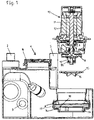
- FIG 1 shows an exploded view of a device with a centrifugal pump that is integrated into a sewage pumping station.
- the sewage lifting plant includes a container 1.
- the container 1 consists of a plastic. This is designed as a collection container for non-pressurized operation. Waste water is temporarily stored and then pumped into a sewer. It proves to be particularly favorable if the nominal volume of the container 1 is less than 500 l, preferably less than 300 l, in particular less than 100 l. In the exemplary embodiment, the nominal volume of the container 1 is approximately 50 l.
- the container 1 has an area with a higher construction height and at least one inlet 2 and an area with a lower construction height, in which the centrifugal pump designed as a unit is arranged.
- the container 1 has an emptying connection 3 .
- the container 1 is provided with a hand hole at its top, which is closed by a lid 4 .
- a sensor for detecting the filling level is arranged in the container 1.
- a float switch is used, for example.
- the container 1 has a ventilation connection 5 .
- the drain water collected in the container 1 is conveyed out via a drain arranged on the container 1 .
- the housing part 6 and the mold are preheated and the temperature is controlled in a controlled manner by means of a heating device during the entire rotation process.
- the temperature is adjusted to the plastic used.
- thermoplastic is used as the plastic granulate. It is preferably a polyethylene (PE-LLD).
- PE-LLD polyethylene
- the container 1 is formed with the desired Wall 7 off.
- the wall 7 of the container 1 encloses the housing part 6 in such a way that no additional sealing is required.
- the melting, contact and solidification of the plastic particles by means of a rotational movement creates a unit of housing part 6 and container 1, in which housing part 6 is at least partially surrounded by a wall 7 of container 1, with a positive connection being created so that housing part 6 with the container 1 forms a structural unit.
- the centrifugal pump comprises an impeller 8 which is connected in a torque-proof manner to a shaft 9 which is driven by a motor 10 .
- the motor 10 comprises a rotor 11 and a stator 12. The motor assembly protrudes vertically from the container 1.
- the arrangement is preferably arranged below a backflow level.
- the waste water is conveyed by the centrifugal pump through a drain into a sewer.
- the impeller 8 of the centrifugal pump is preferably an open radial impeller that does not have a cover disk on the suction side.
- the impeller 8 is designed as a free-flow impeller.
- the impeller 8 has blades between which channels are formed. The blades are arranged on a support disk of the impeller 8 on the pressure side.
- a rotating element 13 of a comminuting arrangement is arranged on the suction side in front of the impeller 8 and is connected to the shaft 9 in a rotationally fixed manner in the exemplary embodiment.
- the rotating element 13 has radial openings 14 .
- the comminution arrangement has a stationary element 15 .
- the fixed element 15 is ring-shaped and encloses the rotating element 13 at least partially during operation.
- the fixed element 15 is provided with a plurality of teeth 16 .
- the teeth 16 protrude into the suction mouth 17 of the housing part 6 of the centrifugal pump.
- the teeth 16 are arranged in an area covered by the openings 14 of the rotating element 13 .
- solid particles in the medium are attracted by the suction of the impeller 8 and thus reach the area of the comminution device formed by the stationary element 15 and the rotating element 13 .
- the solid particles are first held by the fixed element 15 and broken up into small pieces by an interaction of edges of the openings 14 and the teeth 16 . This is done by grasping the parts of the solid that get into the openings 14 and separating them with a pulling cut.
- the openings 14 are round in the exemplary embodiment.
- the stationary element 15 is arranged on the inside of the housing part 6 .
- the fixed element 15 has larger dimensions than the narrowest point of the suction mouth 17 .
- the fixed element 15 rests on a support 18 of the housing part 6 .
- the support 18 is designed as a peripheral shoulder.
- the stationary element 15 is mounted on the inside 19 of the housing part 6 .
- the stationary element 15 of the comminution arrangement is inserted from above into the housing part 6 of the centrifugal pump, so that the comminution device can be maintained can be done from above.
- FIG 2 Figure 1 shows a preferred design of the stationary element 15 of the comminution assembly.
- the fixed element 15 has an outer part 20 and an inner part 21 made of different materials.
- the outer part 20 is ring-shaped and completely surrounds the inner part 21 .
- the inner part 21 consists of a metallic material, which is a chilled cast part in the exemplary embodiment.
- the inner part 21 is designed as a ring and has teeth 16 which are provided with cutting edges 22 .
- the stationary element 15 has a bearing surface 21 on its outer radius, with which the stationary element 15 rests on the bearing 18 of the housing part 6 .
- FIG 3 shows a perspective representation of the stationary element 15 of the comminution arrangement.
- the inner part 21 of the fixed element 15 has projections 24 on its outer radius, which are used for a form-fitting connection between the outer part 20 and the inner part 21 .
- the fixed element 15 is a metal-plastic composite part, with the inner part being made of metal and the outer part being made of a plastic.
- the fixed element 15 is produced by casting the metal inner part into the outer plastic part. A pressureless plastic molding process is used.
- the outer part 20 consists of a duroplast, with PUR199 preferably being used. This material has sufficient stability and high wear resistance as well as high chemical resistance to the substances in the waste water.
- the projections 24 of the inner part 21 create a form-fitting connection between the inner part 21 and the outer part 20 .
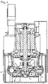
- figure 4 shows the in figure 1 device shown in the form of an exploded drawing in the assembled state.
- the fixed element 15 rests on a support 18 of the housing part 6 on the inside of the housing part 6 and is therefore arranged inside the housing part 6 .
- the fixed element 15 has a larger diameter than the narrowest point of the suction mouth 17, which is formed by the housing part 6.
- the liquid flows from below through the openings 15 to the impeller 8 and is then conveyed radially outwards by the impeller 8 and enters the spiral channel 26 which is enclosed by the housing part 6 .
- the centrifugal pump then conveys the medium out of the container 1 via a nozzle.
Landscapes
- Engineering & Computer Science (AREA)
- Health & Medical Sciences (AREA)
- Life Sciences & Earth Sciences (AREA)
- Hydrology & Water Resources (AREA)
- Public Health (AREA)
- Water Supply & Treatment (AREA)
- Mechanical Engineering (AREA)
- General Engineering & Computer Science (AREA)
- Structures Of Non-Positive Displacement Pumps (AREA)
- Sewage (AREA)
Description
- Die Erfindung betrifft eine Vorrichtung mit einem Behälter zum Sammeln eines Mediums und mindestens einer Kreiselpumpe zum Fördern des Mediums aus dem Behälter und einer Zerkleinerungsanordnung, die einem Laufrad vorgeschaltet ist, wobei die Zerkleinerungsanordnung ein rotierendes Element aufweist, das mit einem feststehenden Element zur Zerkleinerung von festen Beimengungen in dem Medium zusammenwirkt.
- Bei einer solchen Vorrichtung kann es sich beispielsweise um eine Abwasserhebeanlage handeln. Abwasserhebeanlagen leiten Wasser, das unter einer Rückstauebene anfällt, rückstausicher ab. Sie werden zur Förderung von fäkalienfreiem und fäkalienhaltigem Abwasser eingesetzt, das in Kellern von Wohngebäuden anfällt. In einem Behälter wird das anfallende Abwasser gesammelt. Der Füllstand wird über einen Niveausensor erfasst. Wird ein bestimmter Grenzwert erreicht, so schaltet sich eine Kreiselpumpe ein, welche das Abwasser aus dem Kunststoffbehälter fördert.
- In der
DE 10 2007 008 692 A1 wird eine Vorrichtung mit einem Behälter beschrieben, in dem sich Abwasser sammelt. An der Oberseite des Behälters ist eine Öffnung für ein Kreiselpumpenaggregat vorgesehen. Das Gehäuse mit dem Laufrad ragt in das Abwasser hinein. Über einen Saugstutzen wird das Abwasser angesaugt und von der Kreiselpumpe aus dem Behälter herausgefördert. Der Motor des Pumpenaggregats ist mit dem Laufrad über eine Welle verbunden. Das Kreiselpumpenaggregat, bestehend aus dem Pumpengehäuse mit dem Laufrad und dem über eine Welle verbundenen Motor, bildet eine Einheit. Der Motorteil der Kreiselpumpe ragt aus dem Behälter heraus. Die Kreiselpumpe wird von Flanschringen bzw. Platten getragen, die zwischen dem Teil angeordnet sind, der in den Behälter ragt und dem Teil oberhalb des Behälters. Zwischen den Flanschringen bzw. Platten und dem Behälter sind Dichtungsvorrichtungen angeordnet, sodass weder Abwasser noch unangenehme Gerüche aus dem Behälter nach draußen dringen. - Aus der
DE 101 32 084 A1 ist eine Abwasserhebeanlage bekannt, die ein möglichst großes Schaltvolumen besitzt. Da die Grundfläche des Abwasserbehälters und das höchstmögliche Einschaltniveau allgemein durch die Abmessungen der Vorrichtung vorgegeben bzw. begrenzt sind, wird konstruktiv ein sehr niedriges Ausschaltniveau vorgesehen. Dazu ist ein flexibles biegbares Rohrstück mit dessen erstem Ende abgedichtet an der Saugöffnung einer Kreiselpumpe befestigt und dessen zweites bzw. freies Ende befindet sich näher an dem Boden des Behälters als die Saugöffnung. Das flexibel biegbare Material des Rohrstückes hat den Nachteil, dass es bei einer Förderung von mit festen Beimengungen versetzten Flüssigkeiten beim Abpumpvorgang aufgrund des Unterdrucks oder eines Umbiegens durch Feststoffe einklappt und es zu einer Verstopfung der Saugöffnung kommen kann. - In der
DE 10 2015 204 075 A1 wird eine Vorrichtung mit einem Behälter zum Sammeln eines Mediums und einer Kreiselpumpe zum Fördern des Mediums aus dem Behälter beschrieben. Die Kreiselpumpe weist ein Gehäuseteil auf, in dem ein Laufrad angeordnet ist. Das Gehäuseteil ist formschlüssig mit dem Behälter verbunden. - Eine typische Zerkleinerungsanordnung, die dem Laufrad der Kreiselpumpe bei solchen Abwasserhebeanlagen vorgeschaltet ist, zeigt die
DE 37 03 647 C2 . Die Zerkleinerungseinrichtung umfasst ein rotierendes Element, das mit einem feststehenden Element zusammenwirkt. Bei herkömmlichen Abwasserhebeanlagen wird das feststehende Element vor dem Gehäuseteil der Kreiselpumpe an der Außenseite des Gehäuseteils montiert. - Die
EP 1 344 944 B1 zeigt eine Kreiselpumpe mit einer dem Laufrad vorgeschalteten Zerkleinerungseinrichtung für fasrige oder stückige Beimengungen in dem Medium. Die Zerkleinerungseinrichtung weist ein mit dem Pumpenlaufrad umlaufendes rotierendes Element auf. Bei der in derEP 1 344 944 B1 handelt es sich dabei um einen Schneidkopf. Der Schneidkopf wirkt mit einem Schneideinsatz zusammen, der am Gehäuse der Kreiselpumpe feststehend angeordnet ist. - Die
JP 402016387 A DE 10 2008 057 233 A , dieDE 25 36 555 A , dieDE 103 05 726 A1 sowie dieUS 4 454 993 A offenbaren Kreiselpumpen mit Zerkleinerungseinrichtungen. DieDE 10 2014 003 096 A offenbart eine Kreiselpumpe mit einer Zerkleinerungsanordnung, wobei die Kreiselpumpe in einem Abwasserbehälter integriert ist. - Bei herkömmlichen Abwasserhebeanlagen ist eine Wartung der Zerkleinerungsanordnung häufig sehr aufwendig. Insbesondere bei einer Integration von Gehäuseteilen der Kreiselpumpe in den Behälter der Abwasserhebeanlage treten dabei Schwierigkeiten auf.
- Aufgabe der Erfindung ist es, eine Vorrichtung anzugeben, die in einem Behälter gesammeltes Abwasser herausbefördert, ohne dass es zu Verstopfungen kommt. Weiterhin soll eine zuverlässige Abdichtung gegenüber dem gesammelten Abwasser und gegenüber Gerüchen gewährleistet sein. Die Vorrichtung soll sich durch eine einfache Montage und eine zuverlässige Betriebsweise auszeichnen. Weiterhin soll die Vorrichtung leicht zu warten sein und eine hohe Lebensdauer aufweisen.
- Diese Aufgabe wird erfindungsgemäß durch eine Vorrichtung mit den Merkmalen des Anspruchs 1 gelöst. Bevorzugte Varianten sind den Unteransprüchen, der Beschreibung und den Zeichnungen zu entnehmen.
- Erfindungsgemäß weist die Vorrichtung eine Zerkleinerungsanordnung mit einem feststehenden Element auf, das auf der Innenseite eines Gehäuseteils der Kreiselpumpe angeordnet ist. Die erfindungsgemäße Konstruktion ermöglicht es, dass eine Montage und Wartung der Zerkleinerungseinrichtung von oben erfolgen kann, ohne dass das Gehäuseteil der Kreiselpumpe demontiert werden muss. Dies ist insbesondere bei Konstruktionen von großer Bedeutung, bei denen das Gehäuse der Kreiselpumpe in den Behälter der Abwasseranlage integriert ist.
- Bei der vorliegenden Erfindung wird das feststehende Element der Zerkleinerungseinrichtung vorzugsweise innenseitig am Gehäuseteil der Kreiselpumpe montiert. Dabei erweist es sich als günstig, wenn das feststehende Element eine größere Abmessung, vorzugsweise einen größeren Durchmesser, als die schmalste Stelle des Saugmundes der Kreiselpumpe aufweist. Das Gehäuse der Kreiselpumpe bildet einen Saugmund, der vorzugsweise an seiner schmalsten Stelle einen kleineren Durchmesser hat als das feststehende Element der Zerkleinerungseinrichtung. Vorzugsweise handelt es sich bei dem feststehenden Element um eine ringförmige Konstruktion.
- Bei einer bevorzugten Variante der Erfindung liegt das feststehende Element auf einer Auflage des Gehäuseteils auf. Bei der Montage der Kreiselpumpe wird somit zuerst das Gehäuseteil der Kreiselpumpe im Behälter angeordnet und dann wird von oben das feststehende Element auf der Innenseite des Gehäuseteils platziert.
- Bei der Erfindung ist das Gehäuseteil der Kreiselpumpe, das vorzugsweise als Spiralgehäuse ausgebildet ist, formschlüssig mit dem Behälter verbunden. Beispielsweise kann das Gehäuseteil durch Rotationssintern mit dem aus Kunststoff ausgebildeten Behälter formschlüssig verbunden werden.
- Zur Herstellung der Vorrichtung wird dazu das Gehäuseteil der Kreiselpumpe in einer Form angeordnet. Die Form wird auf einem Formträger montiert. In einem nächsten Schritt erfolgt ein Vorheizen der Rotationsform und des Gehäuseteils. In die Form werden Kunststoffpartikel eingebracht. Dabei kann es sich beispielsweise um ein Kunststoffgranulat und/oder ein Kunststoffpulver handeln. Es erfolgt ein Anlegen von Kunststoffpartikeln durch Rotation an die Form und das Gehäuse. Während des Rotationsvorganges wird eine Temperatur aufrechterhalten, die zum Schmelzen der Kunststoffpartikel führt. Die Kunststoffpartikel werden durch die Rotationskräfte an die Form und das Gehäuse gepresst, wo sie schmelzen und erstarren. Dadurch wird ein einheitliches Gebilde aus einem Behälter und einem darin integrierten Gehäuseteil der Kreiselpumpe geschaffen. Es bilden sich Wandungen aus, die einstückig mit dem Behälter ausgebildet sind und die das Gehäuseteil formschlüssig umschließen.
- Die Anwendung eines Rotationsinterverfahrens erzeugt eine formschlüssige Verbindung zwischen dem Gehäuseteil und dem Behälter, die eine hohe Stabilität und eine zuverlässige Abdichtung gewährleistet.
- Vorzugsweise besteht das Gehäuseteil der Kreiselpumpe aus einem metallischen Werkstoff. Beispielsweise kann es sich dabei um einen Gusswerkstoff handeln. Das metallische Gehäuseteil ist dabei derart in die Kunststoffwandungen des Behälters durch das Rotationssinterverfahren eingebettet, dass zusätzliche Dichtelemente zwischen der Außenwand des metallischen Gehäuses und den Wandungen des Behälters entbehrlich sind. Erfindungsgemäß liegen die Wandungen des Behälters dichtend an dem Gehäuse an, sodass kein Medium bzw. Gerüche austreten können.
- Bei einer besonderes günstigen Variante der Erfindung weist das feststehende Element der Zerkleinerungsanordnung einen äußeren Teil auf, der einen inneren Teil zumindest teilweise umgibt. Die Aufteilung des feststehenden Elements in einen äußeren Teil und einen inneren Teil bringt erhebliche Vorteile mit sich. So können die beiden Teile aus unterschiedlichen Materialien gefertigt sein. Vorzugsweise besteht der äußere Teil aus einem Kunststoff. Der innere Teil ist vorzugsweise aus einem Metall gefertigt. Als besonders günstig erweist es sich dabei, wenn das feststehende Element als Metall-Kunststoff-Verbundteil ausgeführt ist. Vorzugsweise wird hierzu ein Hartgussteil konstruktiv mit einer Außenfläche versehen, die Vorsprünge aufweist.
- Weitere Vorteile und Merkmale der Erfindung ergeben sich aus der Beschreibung eines Ausführungsbeispiels anhand von Zeichnungen und aus den Zeichnungen selbst.
- Dabei zeigt:
- Figur 1
- eine Explosionszeichnung einer Abwasserhebeanlage mit einer Kreiselpumpe, die eine Zerkleinerungsanordnung aufweist,
- Figur 2
- einen Schnitt durch ein feststehendes Element der in
Figur 1 dargestellten Zerkleinerungsanordnung , - Figur 3
- eine perspektivische Darstellung des in
Figur 2 dargestellten feststehenden Elementes, - Figur 4
- die zusammengebaute Variante der in
Figur 1 dargestellten Abwasserhebe. -
Figur 1 zeigt in Form einer Explosionszeichnung einer Vorrichtung mit einer Kreiselpumpe, die in eine Abwasserhebeanlage integriert wird. Die Abwasserhebeanlage umfasst einen Behälter 1. Im Ausführungsbeispiel besteht der Behälter 1 aus einem Kunststoff. Dieser ist als Sammelbehälter für einen drucklosen Betrieb ausgelegt. Abwasser wird zwischengespeichert und anschließend in einen Abwasserkanal gefördert. Als besonders günstig erweist es sich, wenn das Nennvolumen des Behälters 1 weniger als 500 I, vorzugsweise weniger als 300 I, insbesondere weniger als 100 I beträgt. Im Ausführungsbeispiel beträgt das Nennvolumen des Behälters 1 ca. 50 I. - Der Behälter 1 weist einen in seiner Bauhöhe höher ausgebildeten Bereich mit mindestens einem Zulauf 2 auf und einen von der Bauhöhe niedriger ausgebildeten Bereich, in dem die als Aggregat ausgeführte Kreiselpumpe angeordnet ist.
- Weiterhin weist der Behälter 1 einen Entleerungsanschluss 3 auf.
- Der Behälter 1 ist an seiner Oberseite mit einem Handloch versehen, das von einem Deckel 4 verschlossen ist. Im Behälter 1 ist ein Sensor zur Erfassung des Füllstandes angeordnet. Beispielsweise kommt dabei ein Schwimmerschalter zum Einsatz. Weiterhin weist der Behälter 1 einen Entlüftungsanschluss 5 auf. Über einen am Behälter 1 angeordneten Ablauf wird das im Behälter 1 gesammelte Ablaufwasser herausgefördert.
- In dem von seiner Bauhöhe niedrigeren Teil des Behälters 1 ist ein Gehäuseteil 6 der Kreiselpumpe formschlüssig integriert. Bei dem Gehäuseteil 6 handelt es sich im Ausführungsbeispiel um ein Spiralgehäuse der Kreiselpumpe. Es besteht aus einem Gusswerkstoff. Das Gehäuseteil 6 wird von Wandungen 7 des aus Kunststoff gefertigten Behälters 1 formschlüssig umschlossen. Die Wandungen 7, welche das Gehäuseteil 6 umschließen, sind einstückig mit dem übrigen Behälter 1 ausgebildet. Das Gehäuseteil 6 ist in den Behälter 1 eingebettet. Im Ausführungsbeispiel wird dies durch Rotationssintern erreicht. Bei diesem Verfahren werden folgende Schritte durchgeführt:
- Befestigung des Gehäuseteils 6 in einer Rotationsform,
- Vorheizen der Rotationsform und des Gehäuseteils 6 mithilfe eines geeigneten Heizgebläses,
- Einfüllung von Kunststoffpartikeln und Verschließen der Form,
- Durchführung eines Rotationsvorgangs unter Aufrechterhaltung der Temperatur,
- leichtes Abkühlen und frühzeitiges Endformen des Kunst-Metall-Verbundteils,
- Abstützen des Gehäuseteils durch eine geeignete Vorrichtung,
- vollständiges Abkühlen der Anordnung,
- mechanische Nachbearbeitung.
- Zum Einrotieren des Gehäuseteils 6 wird dieses zunächst mittels einer geeigneten Verbindung an der Rotationsform befestigt.
- Das Gehäuseteil 6 und die Form werden vorgeheizt und während des gesamten Rotationsprozesses mittels einer Heizvorrichtung kontrolliert temperiert. Die Temperatur wird hierbei an den verwendeten Kunststoff angepasst.
- Im Ausführungsbeispiel wird als Kunststoffgranulat ein Thermoplast eingesetzt. Es handelt sich dabei vorzugsweise um ein Polyethylen (PE-LLD). Durch den Rotationsprozess und ein Aufschmelzen und Erstarren bildet sich der Behälter 1 mit der gewünschten Wandung 7 aus. Durch die Anwendung des Rotationssinterns umschließt die Wandung 7 des Behälters 1 das Gehäuseteil 6 so, dass keine zusätzliche Abdichtung erforderlich ist.
- Durch das Aufschmelzen, Anliegen und Erstarren der Kunststoffpartikel mittels Rotationsbewegung wird eine Einheit des Gehäuseteils 6 und Behälters 1 geschaffen, bei der das Gehäuseteil 6 zumindest teilweise von einer Wandung 7 des Behälters 1 umschlossen ist, wobei eine formschlüssige Verbindung geschaffen wird, sodass das Gehäuseteil 6 mit dem Behälter 1 eine Baueinheit bildet.
- Die Kreiselpumpe umfasst neben dem als Spiralgehäuse ausgebildeten Gehäuseteil 6 ein Laufrad 8, das drehfest mit einer Welle 9 verbunden ist, die von einem Motor 10 angetrieben wird. Der Motor 10 umfasst einen Rotor 11 und einen Stator 12. Das Motoraggregat ragt senkrecht aus dem Behälter 1 heraus.
- Bei einem Betrieb fließt durch den Zulauf 2 Flüssigkeit in den Behälter 1. Bei einem oberen Grenzwert des Füllstands löst ein Schaltsignal den Befehl "Pumpe einschalten" aus. Die Pumpe wird dann durch eine Steuereinrichtung geschaltet. Infolgedessen sinkt der Flüssigkeitsstand im Behälter 1. Sobald ein unterer Grenzwert des Füllstands erreicht ist, wird die Kreiselpumpe wieder ausgeschaltet.
- Die Anordnung ist vorzugsweise unterhalb einer Rückstauebene angeordnet. Das Abwasser wird von der Kreiselpumpe durch einen Ablauf in einen Abwasserkanal gefördert.
- Bei dem Laufrad 8 der Kreiselpumpe handelt es sich vorzugsweise um ein offenes Radialrad, das keine saugseitige Deckscheibe aufweist. Im Ausführungsbeispiel ist das Laufrad 8 als Freistromrad ausgebildet. Das Laufrad 8 besitzt Schaufeln, zwischen denen Kanäle gebildet werden. Die Schaufeln sind auf einer druckseitigen Tragscheibe des Laufrades 8 angeordnet.
- Saugseitig vor dem Laufrad 8 ist ein rotierendes Element 13 einer Zerkleinerungsanordnung angeordnet, das im Ausführungsbeispiel drehfest mit der Welle 9 verbunden ist. Das rotierende Element 13 weist radiale Öffnungen 14 auf.
- Neben dem rotierenden Element 13 weist die Zerkleinerungsanordnung ein feststehendes Element 15 auf. Das feststehende Element 15 ist ringförmig ausgebildet und umschließt im Betrieb das rotierende Element 13 zumindest teilweise. Das feststehende Element 15 ist mit mehreren Zähnen 16 versehen. Die Zähne 16 ragen saugseitig in den Saugmund 17 des Gehäuseteils 6 der Kreiselpumpe. Die Zähne 16 sind dabei in einem von den Öffnungen 14 des rotierenden Elements 13 überstrichenen Bereich angeordnet.
- Beim Betrieb der Kreiselpumpe werden im Medium befindliche Feststoffpartikel vom Sog des Laufrades 8 angezogen und gelangen somit in den Bereich, der von dem feststehenden Element 15 und dem rotierenden Element 13 gebildeten Zerkleinerungseinrichtung. Die Feststoffpartikel werden zunächst von dem feststehenden Element 15 gehalten und durch ein Zusammenwirken von Kanten der Öffnungen 14 und der Zähne 16 in kleine Stücke zerlegt. Dies geschieht dadurch, dass die in die Öffnungen 14 gelangenden Teile des Feststoffs erfasst und mit einem ziehenden Schnitt abgetrennt werden. Die Öffnungen 14 sind im Ausführungsbeispiel rund ausgebildet.
- Das feststehende Element 15 ist erfindungsgemäß auf der Innenseite des Gehäuseteils 6 angeordnet. Das feststehende Element 15 weist größere Abmessungen als die schmalste Stelle des Saugmunds 17 auf. Das feststehende Element 15 liegt auf einer Auflage 18 des Gehäuseteils 6 auf. Die Auflage 18 ist im Ausführungsbeispiel als umlaufender Absatz ausgebildet. Das feststehende Element 15 wird auf der Innenseite 19 des Gehäuseteils 6 montiert.
- Erfindungsgemäß wird das feststehende Element 15 der Zerkleinerungsanordnung von oben in das Gehäuseteil 6 der Kreiselpumpe eingesetzt, sodass eine Wartung der Zerkleinerungseinrichtung von oben erfolgen kann. Dies ist im Ausführungsbeispiel unerlässlich, da das Gehäuseteil 6 formschlüssig in den Behälter 1 integriert ist und somit die Zerkleinerungseinrichtung nicht von unten zugängig ist.
-
Figur 2 zeigt eine bevorzugte Gestaltung des feststehenden Elements 15 der Zerkleinerungsanordnung. Das feststehende Element 15 weist einen äußeren Teil 20 und einen inneren Teil 21 auf, die aus unterschiedlichen Materialien bestehen. Der äußere Teil 20 ist ringförmig ausgebildet und umgibt den inneren Teil 21 vollständig. Der innere Teil 21 besteht aus einem metallischen Werkstoff, wobei es sich im Ausführungsbeispiel um ein Hartgussteil handelt. Der innere Teil 21 ist als Ring ausgebildet und weist Zähne 16 auf, die mit Schneidkanten 22 versehen sind. - Das feststehende Element 15 weist an seinem äußeren Radius eine Auflagefläche 21 auf mit denen das feststehende Element 15 auf der Auflage 18 des Gehäuseteils 6 aufliegt.
-
Figur 3 zeigt eine perspektivische Darstellung des feststehenden Elements 15 der Zerkleinerungsanordnung. Der innere Teil 21 des feststehenden Elements 15 weist an seinem äußeren Radius Vorsprünge 24 auf, die einer formschlüssigen Verbindung zwischen dem äußeren Teil 20 und dem inneren Teil 21 dienen. Bei dem feststehenden Element 15 handelt es sich im Ausführungsbeispiel um ein Metall-Kunststoffverbundteil, wobei der innere Teil aus Metall und der äußere Teil aus einem Kunststoff gefertigt ist. Die Herstellung des feststehenden Elements 15 erfolgt durch Eingießen des metallischen inneren Teils in den äußeren Kunststoffteil. Dabei wird ein druckloses Kunststoffgussverfahren angewendet. Im Ausführungsbeispiel besteht der äußere Teil 20 aus einem Duroplast, wobei vorzugsweise PUR199 verwendet wird. Dieser Werkstoff weist eine ausreichende Stabilität und eine hohe Verschleißfestigkeit sowie eine hohe chemische Beständigkeit gegen die im Abwasser befindlichen Stoffe auf. - Durch die Vorsprünge 24 des inneren Teils 21 wird nach dem Erstarren des Kunststoffgusses des äußeren Teils 20 eine formschlüssige Verbindung zwischen dem inneren Teil 21 und dem äußeren Teil 20 geschaffen.
- Vor der Einbringung des feststehenden Elements 15 in das Gehäuseteil 6 der Kreiselpumpe muss bei der erfindungsgemäßen Ausführung mit einem harten inneren Teil 21 aus einem Metall und einem weichen äußeren Teil 20 aus einem Kunststoff nun nur noch das wesentlich weichere äußere Teil 20 bearbeitet werden. In das äußere Teil 20 des feststehenden Elements 15 werden beispielsweise Bohrungen 25 zur Befestigung des feststehenden Elements 15 am Gehäuseteil 6 mittels Verbindungselementen eingebracht. Weiterhin wird bei der Bearbeitung eine Passung zur Aufnahme des feststehenden Elements 15 auf dem Gehäuseteil 6 vorgesehen.
-
Figur 4 zeigt die inFigur 1 in Form einer Explosionszeichnung dargestellte Vorrichtung im zusammengebauten Zustand. Man erkennt, dass das feststehende Element 15 auf einer Auflage 18 des Gehäuseteils 6 an der Innenseite des Gehäuseteils 6 aufliegt und somit innerhalb des Gehäuseteils 6 angeordnet ist. Das feststehende Element 15 weist einen größeren Durchmesser auf als die schmalste Stelle des Saugmundes 17, der vom Gehäuseteil 6 gebildet wird. Die Flüssigkeit strömt von unten durch die Öffnungen 15 dem Laufrad 8 zu und wird vom Laufrad 8 dann radial nach außen gefördert und tritt in den Spiralkanal 26, der vom Gehäuseteil 6 umschlossen wird. Die Kreiselpumpe fördert dann das Medium über einen Stutzen aus dem Behälter 1 heraus.
Claims (9)
- Vorrichtung mit einem Behälter (1) zum Sammeln eines Mediums und mindestens einer Kreiselpumpe mit einem Laufrad (8) zum Fördern des Mediums aus dem Behälter (1) und einer saugseitig dem Laufrad (8) vorgeschalteten Zerkleinerungsanordnung, wobei die Zerkleinerungsanordnung ein rotierendes Element (13) aufweist, das mit einem feststehenden Element (15) der Zerkleinerungsanordnung zur Zerkleinerung von festen Beimengungen in dem Medium zusammenwirkt, wobei das feststehende Element (15) auf der Innenseite eines Gehäuseteils (6) der Kreiselpumpe angeordnet ist, dadurch gekennzeichnet, dass das Gehäuseteil (6) formschlüssig mit dem Behälter (1) verbunden ist.
- Vorrichtung nach Anspruch 1, dadurch gekennzeichnet, dass das feststehende Element (15) eine größere Abmessung aufweist, als die schmalste Stelle einer Saugöffnung (17) des Gehäuseteils (6) der Kreiselpumpe.
- Vorrichtung nach Anspruch 1 oder 2, dadurch gekennzeichnet, dass das feststehende Element (15) auf einer Auflage (18) des Gehäuseteils (6) aufliegt.
- Vorrichtung nach einem der Ansprüche 1 bis 3, dadurch gekennzeichnet, dass das feststehende Element (15) innenseitig an dem Gehäuseteil (6) montiert ist.
- Vorrichtung nach einem der Ansprüche 1 bis 4, dadurch gekennzeichnet, dass das Gehäuseteil (6) aus einem metallischen Werkstoff besteht und der Behälter (1) aus einem Kunststoff.
- Vorrichtung nach einem der Ansprüche 1 bis 5, dadurch gekennzeichnet, dass das Gehäuseteil (6) zumindest teilweise von einer Wandung (7) des Behälters (1) umschlossen ist, wobei die Wandung (7) einstückig mit dem Behälter (1) ausgebildet ist.
- Vorrichtung nach Anspruch 6,
dadurch gekennzeichnet, dass das Gehäuseteil (6) in die Wandung (7) des Behälters (1) eingebettet ist, wobei das Gehäuseteil (6) vorzugsweise tragend eingebettet ist, insbesondere tragend für ein Antriebsaggregat der Kreiselpumpe. - Vorrichtung nach einem der Ansprüche 1 bis 7, dadurch gekennzeichnet, dass im Gehäuseteil (6) das Laufrad (8) der Kreiselpumpe angeordnet ist.
- Vorrichtung nach einem der Ansprüche 1 bis 8, dadurch gekennzeichnet, dass das feststehende Element (15) einen äußeren ringförmigen Teil (20) aus einem Kunststoff aufweist, der ein inneres ringförmiges Teil (21) aus einem Metall umgibt.
Applications Claiming Priority (2)
| Application Number | Priority Date | Filing Date | Title |
|---|---|---|---|
| DE102016225921.0A DE102016225921A1 (de) | 2016-12-21 | 2016-12-21 | Abwasserhebeanlage mit Schneidwerk |
| PCT/EP2017/082562 WO2018114511A1 (de) | 2016-12-21 | 2017-12-13 | Abwasserhebeanlage mit schneidwerk |
Publications (2)
| Publication Number | Publication Date |
|---|---|
| EP3559362A1 EP3559362A1 (de) | 2019-10-30 |
| EP3559362B1 true EP3559362B1 (de) | 2022-04-06 |
Family
ID=60888386
Family Applications (1)
| Application Number | Title | Priority Date | Filing Date |
|---|---|---|---|
| EP17822614.8A Active EP3559362B1 (de) | 2016-12-21 | 2017-12-13 | Abwasserhebeanlage mit schneidwerk |
Country Status (6)
| Country | Link |
|---|---|
| EP (1) | EP3559362B1 (de) |
| CN (1) | CN110139965B (de) |
| CL (1) | CL2019001764A1 (de) |
| DE (1) | DE102016225921A1 (de) |
| RU (1) | RU2749751C2 (de) |
| WO (1) | WO2018114511A1 (de) |
Families Citing this family (1)
| Publication number | Priority date | Publication date | Assignee | Title |
|---|---|---|---|---|
| TR2023008014A1 (tr) * | 2023-07-10 | 2024-09-23 | Eys Enduestri Makina Sanayi Ve Ticaret Anonim Sirketi | Geli̇şti̇ri̇lmi̇ş bi̇r kesme üni̇tesi̇ne sahi̇p bi̇r pompa |
Family Cites Families (18)
| Publication number | Priority date | Publication date | Assignee | Title |
|---|---|---|---|---|
| DE2411043A1 (de) * | 1974-03-08 | 1975-09-18 | Abs Pumps Ltd | Abwasserpumpe |
| US3961758A (en) * | 1974-08-23 | 1976-06-08 | Peabody Barnes, Inc. | Centrifugal pump with integral grinder |
| JPS5838396A (ja) * | 1981-08-29 | 1983-03-05 | Ebara Corp | グラインダ−ポンプ |
| DE3703647A1 (de) | 1987-02-06 | 1988-08-18 | Klein Schanzlin & Becker Ag | Kreiselpumpe fuer verunreinigte fluessigkeiten |
| JPH061078B2 (ja) * | 1989-05-01 | 1994-01-05 | 株式会社鶴見製作所 | グラインダーポンプ |
| CH689058A5 (de) * | 1994-11-28 | 1998-08-31 | Haeny & Cie Ag | Kreiselpumpe fuer mit Feststoffanteilen belastete Abwaesser. |
| DE10132084A1 (de) | 2001-07-05 | 2003-01-16 | Wilo Gmbh | Abwasser-Hebeanlage mit tiefer Absaugung |
| EP1344944B1 (de) | 2002-03-14 | 2004-06-02 | KSB Aktiengesellschaft | Kreiselpumpe mit Zerkleinerungseinrichtung |
| DE10305726A1 (de) * | 2002-03-14 | 2003-10-02 | Ksb Ag | Kreiselpumpe mit Zerkleinerungseinrichtung |
| DE102007008692A1 (de) | 2007-02-20 | 2008-08-21 | Ksb Aktiengesellschaft | Niveauabhängige Steuerung von Pumpen |
| CN201043529Y (zh) * | 2007-04-27 | 2008-04-02 | 厦门河昌电机有限公司 | 改良型泵浦搅碎装置 |
| DE102008057233A1 (de) * | 2008-11-10 | 2010-05-12 | Orpu Pumpenfabrik Gmbh | Vorrichtung zum Zerkleinern von in flüssigen Medien befindlichen Bestandteilen |
| EP2489799B1 (de) * | 2011-02-16 | 2014-08-20 | Grundfos Management a/s | Abwasserhebeanlage |
| DE102011112580B4 (de) * | 2011-09-08 | 2014-03-20 | Schmalenberger Gmbh & Co. Kg | Selbstansaugende Pumpe mit Schneidwerk |
| DE102014003096A1 (de) * | 2014-03-11 | 2015-09-17 | Homa Pumpenfabrik Gmbh | Hebeanlage für Abwasser |
| DE102015204075A1 (de) | 2015-03-06 | 2016-09-08 | Ksb Aktiengesellschaft | Kunststoffbehälter mit strömungsführendem Bauteil |
| CN104696260A (zh) * | 2015-03-13 | 2015-06-10 | 江苏大学 | 一种新型污水泵切割装置 |
| DE102016200910A1 (de) * | 2016-01-22 | 2017-07-27 | Ksb Aktiengesellschaft | Anlage |
-
2016
- 2016-12-21 DE DE102016225921.0A patent/DE102016225921A1/de not_active Withdrawn
-
2017
- 2017-12-13 CN CN201780082543.4A patent/CN110139965B/zh active Active
- 2017-12-13 EP EP17822614.8A patent/EP3559362B1/de active Active
- 2017-12-13 WO PCT/EP2017/082562 patent/WO2018114511A1/de not_active Ceased
- 2017-12-13 RU RU2019122298A patent/RU2749751C2/ru active
-
2019
- 2019-06-21 CL CL2019001764A patent/CL2019001764A1/es unknown
Also Published As
| Publication number | Publication date |
|---|---|
| EP3559362A1 (de) | 2019-10-30 |
| CN110139965A (zh) | 2019-08-16 |
| CN110139965B (zh) | 2022-06-24 |
| CL2019001764A1 (es) | 2019-09-23 |
| RU2749751C2 (ru) | 2021-06-16 |
| WO2018114511A1 (de) | 2018-06-28 |
| RU2019122298A3 (de) | 2021-01-25 |
| DE102016225921A1 (de) | 2018-06-21 |
| RU2019122298A (ru) | 2021-01-22 |
Similar Documents
| Publication | Publication Date | Title |
|---|---|---|
| DE2117641C3 (de) | Vorrichtung zum Zerkleinern und Abpumpen von pumpbaren Flüssigkeiten | |
| EP2604860A1 (de) | Nassläuferpumpe mit Vorkammer | |
| DE102008032411A1 (de) | Strömungswandler | |
| EP3670920B1 (de) | Ansaugvorrichtung für eine abwasser-tauchpumpe | |
| DE1800446A1 (de) | Kreiselpumpe zum Eintauchen,insbesondere zum Pumpen korrodierender Fluessigkeiten bei hohen Temperaturen | |
| DE102012216196A1 (de) | Pumpe | |
| EP4171439B1 (de) | Abscheider mit herausnehmbarem zentrifugenbehälter | |
| EP2561151B1 (de) | Ablauf mit integrierter pumpe, die einen hydraulisch antrieb aufweist | |
| EP3559362A1 (de) | Abwasserhebeanlage mit schneidwerk | |
| EP3519699B1 (de) | Pumpenanordnung | |
| EP3559479B1 (de) | Kreiselpumpe mit einer zerkleinerungsanordnung | |
| EP3265681B1 (de) | Kunststoffbehälter mit strömungsführendem bauteil | |
| EP2573288B1 (de) | Abwasserhebeanlage | |
| DE102011111860A1 (de) | Vorrichtung und Verfahren zum befestigen einer Schneckenwelle mit einer Antriebseinheit, sowie deren Abdichtung gegen eine wässrige abrassive Flüssigkeit an der Durchbruchstelle vom antriebseitigen Wellenstumpf der Schneckenwelle mit dem Maschinengehäuse | |
| EP3405677B1 (de) | Entlüftungseinrichtung für eine pumpe in einem behälter | |
| EP3090185B1 (de) | Kreiselpumpe mit schneidvorrichtung | |
| EP3480451A1 (de) | Kleinwasserkraftwerk | |
| EP4108935B1 (de) | Schneidring für mit feststoff belastete flüssigkeit einer pumpe | |
| DE102015101344A1 (de) | Separator | |
| EP2573284B1 (de) | Abwasserhebeanlage | |
| DE102011119076A1 (de) | Vorrichtung und Verfahren zum Druckabbau eines Fluids mit darin enthaltenen Granulatkörnern | |
| DE102010022936A1 (de) | Konvexe Strömungsturbine | |
| EP2154300A1 (de) | Abwasserstation | |
| DE102014003096A1 (de) | Hebeanlage für Abwasser | |
| DE202011004153U1 (de) | Pressschneckenseparator |
Legal Events
| Date | Code | Title | Description |
|---|---|---|---|
| STAA | Information on the status of an ep patent application or granted ep patent |
Free format text: STATUS: UNKNOWN |
|
| STAA | Information on the status of an ep patent application or granted ep patent |
Free format text: STATUS: THE INTERNATIONAL PUBLICATION HAS BEEN MADE |
|
| PUAI | Public reference made under article 153(3) epc to a published international application that has entered the european phase |
Free format text: ORIGINAL CODE: 0009012 |
|
| STAA | Information on the status of an ep patent application or granted ep patent |
Free format text: STATUS: REQUEST FOR EXAMINATION WAS MADE |
|
| 17P | Request for examination filed |
Effective date: 20190701 |
|
| AK | Designated contracting states |
Kind code of ref document: A1 Designated state(s): AL AT BE BG CH CY CZ DE DK EE ES FI FR GB GR HR HU IE IS IT LI LT LU LV MC MK MT NL NO PL PT RO RS SE SI SK SM TR |
|
| AX | Request for extension of the european patent |
Extension state: BA ME |
|
| DAV | Request for validation of the european patent (deleted) | ||
| DAX | Request for extension of the european patent (deleted) | ||
| GRAP | Despatch of communication of intention to grant a patent |
Free format text: ORIGINAL CODE: EPIDOSNIGR1 |
|
| STAA | Information on the status of an ep patent application or granted ep patent |
Free format text: STATUS: GRANT OF PATENT IS INTENDED |
|
| INTG | Intention to grant announced |
Effective date: 20211122 |
|
| GRAS | Grant fee paid |
Free format text: ORIGINAL CODE: EPIDOSNIGR3 |
|
| GRAA | (expected) grant |
Free format text: ORIGINAL CODE: 0009210 |
|
| STAA | Information on the status of an ep patent application or granted ep patent |
Free format text: STATUS: THE PATENT HAS BEEN GRANTED |
|
| AK | Designated contracting states |
Kind code of ref document: B1 Designated state(s): AL AT BE BG CH CY CZ DE DK EE ES FI FR GB GR HR HU IE IS IT LI LT LU LV MC MK MT NL NO PL PT RO RS SE SI SK SM TR |
|
| REG | Reference to a national code |
Ref country code: GB Ref legal event code: FG4D Free format text: NOT ENGLISH |
|
| REG | Reference to a national code |
Ref country code: CH Ref legal event code: EP |
|
| REG | Reference to a national code |
Ref country code: AT Ref legal event code: REF Ref document number: 1481457 Country of ref document: AT Kind code of ref document: T Effective date: 20220415 |
|
| REG | Reference to a national code |
Ref country code: IE Ref legal event code: FG4D Free format text: LANGUAGE OF EP DOCUMENT: GERMAN |
|
| REG | Reference to a national code |
Ref country code: DE Ref legal event code: R096 Ref document number: 502017012935 Country of ref document: DE |
|
| REG | Reference to a national code |
Ref country code: LT Ref legal event code: MG9D |
|
| REG | Reference to a national code |
Ref country code: NL Ref legal event code: MP Effective date: 20220406 |
|
| PG25 | Lapsed in a contracting state [announced via postgrant information from national office to epo] |
Ref country code: NL Free format text: LAPSE BECAUSE OF FAILURE TO SUBMIT A TRANSLATION OF THE DESCRIPTION OR TO PAY THE FEE WITHIN THE PRESCRIBED TIME-LIMIT Effective date: 20220406 |
|
| PG25 | Lapsed in a contracting state [announced via postgrant information from national office to epo] |
Ref country code: SE Free format text: LAPSE BECAUSE OF FAILURE TO SUBMIT A TRANSLATION OF THE DESCRIPTION OR TO PAY THE FEE WITHIN THE PRESCRIBED TIME-LIMIT Effective date: 20220406 Ref country code: PT Free format text: LAPSE BECAUSE OF FAILURE TO SUBMIT A TRANSLATION OF THE DESCRIPTION OR TO PAY THE FEE WITHIN THE PRESCRIBED TIME-LIMIT Effective date: 20220808 Ref country code: NO Free format text: LAPSE BECAUSE OF FAILURE TO SUBMIT A TRANSLATION OF THE DESCRIPTION OR TO PAY THE FEE WITHIN THE PRESCRIBED TIME-LIMIT Effective date: 20220706 Ref country code: LT Free format text: LAPSE BECAUSE OF FAILURE TO SUBMIT A TRANSLATION OF THE DESCRIPTION OR TO PAY THE FEE WITHIN THE PRESCRIBED TIME-LIMIT Effective date: 20220406 Ref country code: HR Free format text: LAPSE BECAUSE OF FAILURE TO SUBMIT A TRANSLATION OF THE DESCRIPTION OR TO PAY THE FEE WITHIN THE PRESCRIBED TIME-LIMIT Effective date: 20220406 Ref country code: GR Free format text: LAPSE BECAUSE OF FAILURE TO SUBMIT A TRANSLATION OF THE DESCRIPTION OR TO PAY THE FEE WITHIN THE PRESCRIBED TIME-LIMIT Effective date: 20220707 Ref country code: FI Free format text: LAPSE BECAUSE OF FAILURE TO SUBMIT A TRANSLATION OF THE DESCRIPTION OR TO PAY THE FEE WITHIN THE PRESCRIBED TIME-LIMIT Effective date: 20220406 Ref country code: ES Free format text: LAPSE BECAUSE OF FAILURE TO SUBMIT A TRANSLATION OF THE DESCRIPTION OR TO PAY THE FEE WITHIN THE PRESCRIBED TIME-LIMIT Effective date: 20220406 Ref country code: BG Free format text: LAPSE BECAUSE OF FAILURE TO SUBMIT A TRANSLATION OF THE DESCRIPTION OR TO PAY THE FEE WITHIN THE PRESCRIBED TIME-LIMIT Effective date: 20220706 |
|
| PG25 | Lapsed in a contracting state [announced via postgrant information from national office to epo] |
Ref country code: RS Free format text: LAPSE BECAUSE OF FAILURE TO SUBMIT A TRANSLATION OF THE DESCRIPTION OR TO PAY THE FEE WITHIN THE PRESCRIBED TIME-LIMIT Effective date: 20220406 Ref country code: PL Free format text: LAPSE BECAUSE OF FAILURE TO SUBMIT A TRANSLATION OF THE DESCRIPTION OR TO PAY THE FEE WITHIN THE PRESCRIBED TIME-LIMIT Effective date: 20220406 Ref country code: LV Free format text: LAPSE BECAUSE OF FAILURE TO SUBMIT A TRANSLATION OF THE DESCRIPTION OR TO PAY THE FEE WITHIN THE PRESCRIBED TIME-LIMIT Effective date: 20220406 Ref country code: IS Free format text: LAPSE BECAUSE OF FAILURE TO SUBMIT A TRANSLATION OF THE DESCRIPTION OR TO PAY THE FEE WITHIN THE PRESCRIBED TIME-LIMIT Effective date: 20220806 |
|
| REG | Reference to a national code |
Ref country code: DE Ref legal event code: R097 Ref document number: 502017012935 Country of ref document: DE |
|
| PG25 | Lapsed in a contracting state [announced via postgrant information from national office to epo] |
Ref country code: SM Free format text: LAPSE BECAUSE OF FAILURE TO SUBMIT A TRANSLATION OF THE DESCRIPTION OR TO PAY THE FEE WITHIN THE PRESCRIBED TIME-LIMIT Effective date: 20220406 Ref country code: SK Free format text: LAPSE BECAUSE OF FAILURE TO SUBMIT A TRANSLATION OF THE DESCRIPTION OR TO PAY THE FEE WITHIN THE PRESCRIBED TIME-LIMIT Effective date: 20220406 Ref country code: RO Free format text: LAPSE BECAUSE OF FAILURE TO SUBMIT A TRANSLATION OF THE DESCRIPTION OR TO PAY THE FEE WITHIN THE PRESCRIBED TIME-LIMIT Effective date: 20220406 Ref country code: EE Free format text: LAPSE BECAUSE OF FAILURE TO SUBMIT A TRANSLATION OF THE DESCRIPTION OR TO PAY THE FEE WITHIN THE PRESCRIBED TIME-LIMIT Effective date: 20220406 Ref country code: DK Free format text: LAPSE BECAUSE OF FAILURE TO SUBMIT A TRANSLATION OF THE DESCRIPTION OR TO PAY THE FEE WITHIN THE PRESCRIBED TIME-LIMIT Effective date: 20220406 Ref country code: CZ Free format text: LAPSE BECAUSE OF FAILURE TO SUBMIT A TRANSLATION OF THE DESCRIPTION OR TO PAY THE FEE WITHIN THE PRESCRIBED TIME-LIMIT Effective date: 20220406 |
|
| PLBE | No opposition filed within time limit |
Free format text: ORIGINAL CODE: 0009261 |
|
| STAA | Information on the status of an ep patent application or granted ep patent |
Free format text: STATUS: NO OPPOSITION FILED WITHIN TIME LIMIT |
|
| 26N | No opposition filed |
Effective date: 20230110 |
|
| PG25 | Lapsed in a contracting state [announced via postgrant information from national office to epo] |
Ref country code: AL Free format text: LAPSE BECAUSE OF FAILURE TO SUBMIT A TRANSLATION OF THE DESCRIPTION OR TO PAY THE FEE WITHIN THE PRESCRIBED TIME-LIMIT Effective date: 20220406 |
|
| PG25 | Lapsed in a contracting state [announced via postgrant information from national office to epo] |
Ref country code: SI Free format text: LAPSE BECAUSE OF FAILURE TO SUBMIT A TRANSLATION OF THE DESCRIPTION OR TO PAY THE FEE WITHIN THE PRESCRIBED TIME-LIMIT Effective date: 20220406 |
|
| REG | Reference to a national code |
Ref country code: BE Ref legal event code: MM Effective date: 20221231 |
|
| PG25 | Lapsed in a contracting state [announced via postgrant information from national office to epo] |
Ref country code: LU Free format text: LAPSE BECAUSE OF NON-PAYMENT OF DUE FEES Effective date: 20221213 |
|
| PG25 | Lapsed in a contracting state [announced via postgrant information from national office to epo] |
Ref country code: IE Free format text: LAPSE BECAUSE OF NON-PAYMENT OF DUE FEES Effective date: 20221213 |
|
| PG25 | Lapsed in a contracting state [announced via postgrant information from national office to epo] |
Ref country code: BE Free format text: LAPSE BECAUSE OF NON-PAYMENT OF DUE FEES Effective date: 20221231 |
|
| PG25 | Lapsed in a contracting state [announced via postgrant information from national office to epo] |
Ref country code: IT Free format text: LAPSE BECAUSE OF FAILURE TO SUBMIT A TRANSLATION OF THE DESCRIPTION OR TO PAY THE FEE WITHIN THE PRESCRIBED TIME-LIMIT Effective date: 20220406 |
|
| PG25 | Lapsed in a contracting state [announced via postgrant information from national office to epo] |
Ref country code: HU Free format text: LAPSE BECAUSE OF FAILURE TO SUBMIT A TRANSLATION OF THE DESCRIPTION OR TO PAY THE FEE WITHIN THE PRESCRIBED TIME-LIMIT; INVALID AB INITIO Effective date: 20171213 |
|
| PG25 | Lapsed in a contracting state [announced via postgrant information from national office to epo] |
Ref country code: CY Free format text: LAPSE BECAUSE OF FAILURE TO SUBMIT A TRANSLATION OF THE DESCRIPTION OR TO PAY THE FEE WITHIN THE PRESCRIBED TIME-LIMIT Effective date: 20220406 |
|
| PG25 | Lapsed in a contracting state [announced via postgrant information from national office to epo] |
Ref country code: MK Free format text: LAPSE BECAUSE OF FAILURE TO SUBMIT A TRANSLATION OF THE DESCRIPTION OR TO PAY THE FEE WITHIN THE PRESCRIBED TIME-LIMIT Effective date: 20220406 |
|
| PG25 | Lapsed in a contracting state [announced via postgrant information from national office to epo] |
Ref country code: MC Free format text: LAPSE BECAUSE OF FAILURE TO SUBMIT A TRANSLATION OF THE DESCRIPTION OR TO PAY THE FEE WITHIN THE PRESCRIBED TIME-LIMIT Effective date: 20220406 |
|
| PG25 | Lapsed in a contracting state [announced via postgrant information from national office to epo] |
Ref country code: TR Free format text: LAPSE BECAUSE OF FAILURE TO SUBMIT A TRANSLATION OF THE DESCRIPTION OR TO PAY THE FEE WITHIN THE PRESCRIBED TIME-LIMIT Effective date: 20220406 Ref country code: MC Free format text: LAPSE BECAUSE OF FAILURE TO SUBMIT A TRANSLATION OF THE DESCRIPTION OR TO PAY THE FEE WITHIN THE PRESCRIBED TIME-LIMIT Effective date: 20220406 |
|
| PG25 | Lapsed in a contracting state [announced via postgrant information from national office to epo] |
Ref country code: MT Free format text: LAPSE BECAUSE OF FAILURE TO SUBMIT A TRANSLATION OF THE DESCRIPTION OR TO PAY THE FEE WITHIN THE PRESCRIBED TIME-LIMIT Effective date: 20220406 |
|
| PG25 | Lapsed in a contracting state [announced via postgrant information from national office to epo] |
Ref country code: BG Free format text: LAPSE BECAUSE OF FAILURE TO SUBMIT A TRANSLATION OF THE DESCRIPTION OR TO PAY THE FEE WITHIN THE PRESCRIBED TIME-LIMIT Effective date: 20220406 |
|
| PG25 | Lapsed in a contracting state [announced via postgrant information from national office to epo] |
Ref country code: BG Free format text: LAPSE BECAUSE OF FAILURE TO SUBMIT A TRANSLATION OF THE DESCRIPTION OR TO PAY THE FEE WITHIN THE PRESCRIBED TIME-LIMIT Effective date: 20220406 |
|
| REG | Reference to a national code |
Ref country code: CH Ref legal event code: U11 Free format text: ST27 STATUS EVENT CODE: U-0-0-U10-U11 (AS PROVIDED BY THE NATIONAL OFFICE) Effective date: 20260101 |
|
| PGFP | Annual fee paid to national office [announced via postgrant information from national office to epo] |
Ref country code: GB Payment date: 20251229 Year of fee payment: 9 |
|
| PGFP | Annual fee paid to national office [announced via postgrant information from national office to epo] |
Ref country code: AT Payment date: 20251222 Year of fee payment: 9 |
|
| PGFP | Annual fee paid to national office [announced via postgrant information from national office to epo] |
Ref country code: FR Payment date: 20251223 Year of fee payment: 9 |
|
| PGFP | Annual fee paid to national office [announced via postgrant information from national office to epo] |
Ref country code: DE Payment date: 20251223 Year of fee payment: 9 |
|
| PGFP | Annual fee paid to national office [announced via postgrant information from national office to epo] |
Ref country code: CH Payment date: 20260101 Year of fee payment: 9 |