EP3558156B1 - Zahnmedizinischer einsatz zur verbindung eines zahnmedizinischen implantats mit einem zahnmedizinischen aufsatz - Google Patents
Zahnmedizinischer einsatz zur verbindung eines zahnmedizinischen implantats mit einem zahnmedizinischen aufsatz Download PDFInfo
- Publication number
- EP3558156B1 EP3558156B1 EP17829635.6A EP17829635A EP3558156B1 EP 3558156 B1 EP3558156 B1 EP 3558156B1 EP 17829635 A EP17829635 A EP 17829635A EP 3558156 B1 EP3558156 B1 EP 3558156B1
- Authority
- EP
- European Patent Office
- Prior art keywords
- dental
- cap
- implant
- insert
- receptacle
- Prior art date
- Legal status (The legal status is an assumption and is not a legal conclusion. Google has not performed a legal analysis and makes no representation as to the accuracy of the status listed.)
- Active
Links
Images



Classifications
-
- A—HUMAN NECESSITIES
- A61—MEDICAL OR VETERINARY SCIENCE; HYGIENE
- A61C—DENTISTRY; APPARATUS OR METHODS FOR ORAL OR DENTAL HYGIENE
- A61C8/00—Means to be fixed to the jaw-bone for consolidating natural teeth or for fixing dental prostheses thereon; Dental implants; Implanting tools
- A61C8/0048—Connecting the upper structure to the implant, e.g. bridging bars
- A61C8/005—Connecting devices for joining an upper structure with an implant member, e.g. spacers
- A61C8/0062—Catch or snap type connection
-
- A—HUMAN NECESSITIES
- A61—MEDICAL OR VETERINARY SCIENCE; HYGIENE
- A61C—DENTISTRY; APPARATUS OR METHODS FOR ORAL OR DENTAL HYGIENE
- A61C8/00—Means to be fixed to the jaw-bone for consolidating natural teeth or for fixing dental prostheses thereon; Dental implants; Implanting tools
- A61C8/0048—Connecting the upper structure to the implant, e.g. bridging bars
- A61C8/005—Connecting devices for joining an upper structure with an implant member, e.g. spacers
- A61C8/0063—Connecting devices for joining an upper structure with an implant member, e.g. spacers with an internal sleeve
-
- A—HUMAN NECESSITIES
- A61—MEDICAL OR VETERINARY SCIENCE; HYGIENE
- A61C—DENTISTRY; APPARATUS OR METHODS FOR ORAL OR DENTAL HYGIENE
- A61C8/00—Means to be fixed to the jaw-bone for consolidating natural teeth or for fixing dental prostheses thereon; Dental implants; Implanting tools
- A61C8/0048—Connecting the upper structure to the implant, e.g. bridging bars
- A61C8/005—Connecting devices for joining an upper structure with an implant member, e.g. spacers
- A61C8/0065—Connecting devices for joining an upper structure with an implant member, e.g. spacers with expandable or compressible means
-
- A—HUMAN NECESSITIES
- A61—MEDICAL OR VETERINARY SCIENCE; HYGIENE
- A61C—DENTISTRY; APPARATUS OR METHODS FOR ORAL OR DENTAL HYGIENE
- A61C8/00—Means to be fixed to the jaw-bone for consolidating natural teeth or for fixing dental prostheses thereon; Dental implants; Implanting tools
- A61C8/0048—Connecting the upper structure to the implant, e.g. bridging bars
- A61C8/005—Connecting devices for joining an upper structure with an implant member, e.g. spacers
- A61C8/0054—Connecting devices for joining an upper structure with an implant member, e.g. spacers having a cylindrical implant connecting part
-
- A—HUMAN NECESSITIES
- A61—MEDICAL OR VETERINARY SCIENCE; HYGIENE
- A61C—DENTISTRY; APPARATUS OR METHODS FOR ORAL OR DENTAL HYGIENE
- A61C8/00—Means to be fixed to the jaw-bone for consolidating natural teeth or for fixing dental prostheses thereon; Dental implants; Implanting tools
- A61C8/0048—Connecting the upper structure to the implant, e.g. bridging bars
- A61C8/005—Connecting devices for joining an upper structure with an implant member, e.g. spacers
- A61C8/0068—Connecting devices for joining an upper structure with an implant member, e.g. spacers with an additional screw
Definitions
- the present invention relates to a dental insert for connecting a dental implant to a dental attachment, as well as an arrangement of the dental insert with the dental attachment and a tooth replacement.
- the JP 2011 120 723 A discloses a three-part denture with an implant.
- the implant has a terminal pin on which a sleeve-shaped clamping means is placed. It is an attachment because the clamping means does not protrude into the body of the implant. Finally, another dental attachment, the so-called abutment, is placed on this sleeve-shaped attachment.
- the construction has the disadvantage that side forces are only absorbed by the pin, which limits the choice of materials. With a ceramic implant, for example, there is the risk that the pin will break due to the unfavorable mechanical force distribution.
- the US 2016/0206409 A1 discloses a multi-part implant unit with an implant in the form of a hollow cylindrical screw, as well as with a dowel-like insert arranged therein and a dental attachment with a screw bolt.
- the connection between the insert, attachment and implant is made by a screw connection.
- the US 2016/0354183 A1 discloses an implant unit with an implant, a sleeve that can be inserted in some areas and a screw-on dental attachment.
- the object of the present invention is to achieve a connection between a dental implant and a dental attachment which is hygienic, and preferably biomechanically stable and form-fitting, and has only low mechanical loads or advantageous force distributions.
- the invention solves this problem by a dental insert for connecting a dental implant to a dental attachment with the features of claim 1, as well as an arrangement with the features of claim 9 and a dental prosthesis with the features of claim 15.
- a dental insert for connecting a dental implant to a dental attachment.
- a corresponding attachment can preferably be designed as a tooth crown or a so-called abutment.
- This dental insert has at least two interfaces.
- a first interface is formed in interaction with the attachment for fixing the dental insert to the implant by at least one latching and / or clamping connection.
- This first interface can, for example, have a receptacle with latching lugs or the like into which a projection of the implant can be inserted.
- the receiving wall can then receive a material reinforcement through the connection of the dental insert with the dental attachment, so that the attachment is fixed with the implant in a form-fitting manner by latching or clamping.
- the second interface is designed to fix the attachment. This can preferably be done by screwing.
- a screw connection and a screw channel in the context of the present invention include also bayonet connections, so that two elements are brought into engagement with one another by a rotary movement analogous to a conventional screw.
- the dental insert is designed as a plug-in cap with a cap opening, a cap base and a cap surface.
- the cap base is not necessarily a closed surface, but it can advantageously have recesses.
- the cap base has a receptacle with a receptacle space for attachment to a projection of the implant.
- the receptacle can advantageously have an area for receiving a thickened projection and an adjoining area with a cross-sectional narrowing of the receptacle.
- the plug-in cap can have a longitudinal axis, the receptacle advantageously being arranged centered on the longitudinal axis.
- the receptacle preferably has a receptacle wall which delimits the receptacle space, with a cap space extending adjacent to the receptacle wall, into which the attachment can be inserted in regions.
- the receiving wall can advantageously have a wall thickness of less than 1 mm, so that a limited deformability of the receiving wall for introducing the projection into the receiving space is guaranteed.
- the plug-in cap can also advantageously have a gap-shaped recess which extends over at least regionally over the cap base and at least regionally over the cap sleeve.
- This recess is a type of material weakening and allows a limited variability of the opening of the recess for receiving the projection of the implant.
- the second of the at least two interfaces can be designed as a screw channel.
- a threaded or bayonet channel is to be understood as a screw channel in the context of the present invention.
- the second interface can also be a pin-like projection. This can be inserted into a recess of the receptacle and encapsulated, glued or latched in the recess. An arrangement is thereby formed which is referred to below as an arrangement according to the invention.
- a potting compound preferably a curable potting compound
- the potting compound in the cured state, particularly preferably has a lower hardness than the attachment in order, for example, to enable the potting compound to be bored out.
- a latching element e.g. an expanding head, which forms a form fit with a stop surface of the attachment.
- the receiving wall can advantageously have projections which protrude into the receiving space. These projections engage behind a projection thickening and enable the fixation of the projection to be strengthened and prevent the projection from being displaced along the axial direction of the longitudinal axis of the dental insert.
- the insert can advantageously comprise at least 45% by weight, preferably at least 90% by weight, of a polyether ketone.
- a material is suitable for hygienic use in the moist oral cavity and also has material properties with regard to material deformation, which have an advantageous effect on the flexibility of the opening width of the receptacle.
- Dental use is advantageous, in particular by releasing the form fit with the attachment, it can be exchanged and fixed in the implant.
- the material of the dental insert can comprise at least one antibacterial, disinfectant and / or anti-inflammatory active ingredient, which can be replaced during a regular check. Because the insert can be exchanged, the active ingredient can always be renewed.
- the dosage of active ingredient in dental use can be selected depending on the degree of the clinical picture. There may be applications with no, low or high dosage of active ingredient, which depending on requirements, e.g. Degree of inflammation, can be selected.
- the dental insert has an edge which protrudes from the cap surface in the radial direction to the longitudinal axis of the plug-in cap and thus protects the area between the implant and the insert from soiling and the like.
- the dental insert can have a swellable material or consist of such a material.
- swellable means that when a liquid, in particular water and / or saliva, is absorbed, there is an increase in volume by at least 2 percent by volume, preferably at least 5 percent by volume. This results in a sealing effect, so that fluid (blood, saliva or the like) cannot penetrate into the deeper area of the denture and rot there. Accordingly, this is accompanied by a lower odor development and a reduced risk of infection.
- the swelling of the material results in better biomechanical stabilization in the receptacle of the implant.
- an arrangement with an attachment and the insert according to the invention is also according to the invention.
- These two elements can be combined to form a unit when used as intended or even by the manufacturer, or they can be sold as combinable elements.
- the dental insert and the dental attachment can be dimensioned relative to one another.
- the elements of the arrangement can be sold separately from one another before their intended use, however, in a package. This is also to be understood as an arrangement within the scope of the present invention.
- connection of the two elements can be achieved by a mechanical connecting means.
- the attachment has an annular end section which can be positioned in the cap space.
- a ring-shaped end section is also to be understood in particular as a ring which has interruptions and arc-shaped ring segments which preferably lie on a common ring plane.
- the volume of the cap space preferably the entire cap space, is filled by the attachment.
- the annular end section of the attachment can rest against the receiving wall of the receiving space.
- the ring-shaped end section of the attachment can encompass the receptacle of the dental insert at least in some areas in such a way that the opening width of the receptacle is prevented from expanding radially.
- the maximum opening width of the receptacle is limited by the grip around the attachment.
- the attachment in particular the ring-shaped end section, can have at least one recess and / or a projection which, with a corresponding projection and / or a corresponding recess of the insert, forms a form fit to prevent rotation.
- the annular end section can have gaps which run parallel to the longitudinal axis of the insert and which interrupt the annular shape of the end section. As a result, a certain flexibility can be achieved in the area of the end section.
- a tooth replacement according to the invention comprises an arrangement according to the invention and an implant, the implant having a longitudinal axis A and the implant being at least partially shell-shaped with a shell space and having a projection, in particular a projection on the longitudinal axis, which extends into the shell space.
- the implant can also interface with a jawbone, e.g. in the form of a thread.
- the interfaces of the dental prosthesis are preferably permanently connected to one another, e.g. jammed, and in this preferred variant can only be achieved by a material-destroying intervention, e.g. Boring, being separated from each other. This prevents unintentional loosening of the parts during the everyday intended use of the dental prosthesis.
- the dental prosthesis is preferably designed such that the two aforementioned interfaces, that is to say the interface between the insert and the attachment and the interface between the insert and the implant, are within the shell space of the implant are arranged. This creates a hygienic connection and minimizes the risk of spreading inflammation.
- the implant and the dental attachment should be spatially separated from one another by the dental insert in such a way that there is no material contact between the implant and the dental attachment. This reduces friction between the two elements, so that the insert also has a buffer effect in the mechanical interaction.
- Figures 3 and 4 show a three-part structure of a tooth replacement 1 according to the invention. This comprises an implant 2, a plug-in cap 3 according to the invention, and an attachment 4.
- the implant 2 itself can have a shell-shaped design, at least in some areas, with a shell opening 5 and a shell space 6 for receiving the plug-in cap 3 and the attachment 4.
- the implant 2 can also have a thread area for connecting the implant 2 and the entire dental prosthesis 1 to a jawbone.
- the plug-in cap 3 is arranged on the implant 2 in a form-fitting manner.
- the attachment 4 is pushed onto the plug-in cap.
- the shell-shaped implant 2 has a bottom area 7, in particular a closed bottom area, in which a projection 8 is arranged, which protrudes into the shell space 6.
- the projection has a projection thickening 9, for example a terminal projection head, and a projection shaft 10.
- the plug-in cap 3, which is shown in detail in FIG Figs. 1 and 2 is shown in more detail.
- the plug-in cap 3 has a cap space 24 with a cap opening 11, with an opening plane which runs essentially parallel to the opening plane of the shell opening 5.
- the plug-in cap also has a longitudinal axis A.
- the plug-in cap 3 has a cap base 12 with a sleeve-shaped receptacle 13 in which the projection 8 of the shell-shaped implant 2 can be arranged.
- the sleeve-shaped receptacle 13 has edge-side projections 15 which protrude into a receiving space formed by a receiving wall 27 of the receptacle 13.
- the edge-side projections 15 are arranged between the projection thickening 9 and the cap base 12 and prevent the push-in cap 1 from being displaceable along the longitudinal axis A with respect to the shell-shaped implant 2.
- the plug-in cap 3 can essentially be subdivided into the terminal cap base 12 and into a cap surface 14.
- the cap surface 14 essentially has the shape of the inner contour of an implant wall of the implant 2 that delimits the shell space 6.
- the plug-in cap 3 has at least one gap-shaped recess 16 which extends along the cap base and in some areas along the cap surface 14.
- the gap-shaped recess 16 is a kind of material weakening of the insertion cap 3 in the area of the cap base 12 and enables the opening width of the sleeve-shaped receptacle 13 to be changed, so that the insertion cap 3 can be plugged and unplugged onto the projection 8 without force or by overcoming only slight restoring forces caused by material deformation is.
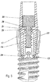
- the plug-in cap 3 has an interface 17 above, that is to say towards the cap opening 11, for connection to the attachment 4, as shown particularly well in FIG Fig. 5 is recognizable.
- the receptacle 13 ' is only indicated schematically.
- the interface 17 can preferably be designed as part of a guide channel, in particular as a screw channel 18. This can extend centered along the longitudinal axis A of the plug-in cap 3.
- the attachment 4 can be designed as a so-called abutment, that is to say an intermediate element between the artificial tooth crown and the implant 2, or can itself be designed as a tooth crown.
- the attachment 4 is at least partially sleeve-shaped, the guide channel extending as a screw channel 18 through the plug-in cap and as a cylindrical cavity through the attachment 4 and running along the longitudinal axis A. Within this guide channel there are stop surfaces 25 for stopping a screw head 20 of a mechanical connecting means 21, in particular a screw, arranged.
- the screw also has a thread 22 which engages in the screw channel 18 of the interface 17.
- the attachment 4 has an annular end region 26 made up of ring sections and interruptions which together define a ring.
- the guide channel extends at the end over the outside of the sleeve-shaped receptacle 13 of the plug-in cap 3 and rests against it in a non-positive manner. This results in a material reinforcement in the region of the receptacle 13 of the insert cap 3, so that the opening width d can no longer be varied or can only be varied to a very limited extent.
- the attachment 4 serves as a locking element which achieves a fixation through a form fit between the plug-in cap 3 and the implant.
- the attachment 4 is in turn connected to the plug-in cap 3 by the mechanical connecting means. By releasing the connecting means, the attachment 4 can be released from the plug-in cap and the plug-in cap 3 can be removed from the implant.
- the plug-in cap can thus be exchanged.
- the mechanical connecting means only connects the attachment 4 to the implant 2 indirectly via the plug-in cap.
- the plug-in cap thus serves as an exchangeable connecting means between these two elements of the dental prosthesis and can be exchanged for reasons of hygiene.
- the plug-in cap can advantageously be made of plastic and contain an antimicrobial agent, e.g. a silver compound.
- the plug-in cap also has an edge 23 which protrudes radially with respect to the cap jacket surface and which delimits the cap opening, this edge resting on the implant and at least partially covering an edge-side end face of the implant.
- the attachment 4 can also have one or more projections 19, recesses and / or depressions which are connected to corresponding projections, depressions and / or recesses, e.g. the gap-shaped recess 16, in the plug-in cap 3, form a form fit to prevent the attachment 4 from rotating with respect to the plug-in cap 3.
- the plug-in cap 3 can preferably be formed from a polyether ketone, in particular from a PEEK, PEKK and / or CF-PEEK.
- the push-in cap particularly preferably comprises an antibacterial and / or anti-inflammatory active ingredient.
- the plug-in cap 3 can also be a coupling point, e.g. have a thread for connection to an insertion aid, through which the insertion sleeve can be inserted into the shell space 6 of the implant 2 or removed from the implant 2.
- the mechanical connecting means for connecting the attachment 4 to the plug-in cap 3 can be designed as a titanium or gold screw. Because the connection to the implant 2 is made via the plug-in cap 3, there is no risk of mechanical damage to the implant from the mechanical connecting means.
- a metallic screw for example made of CF-PEEK, can be used.
- the end of the channel 18 can be closed with a stopper (not shown).
- the implant 2 itself can also be formed from zirconium, titanium and / or PEEK. It is also possible for the implant 2 and / or the mechanical connecting means to consist of a non-resorbable xerogenic or allogeneic material, for example cattle bones, in some areas or completely.
- the attachment 4 can be made of ceramic materials, zirconium oxide, glass material, metal-ceramic hybrid materials, in particular cermets materials and the like.
- the implant can also be made from a ceramic material.
- Figures 6a-6c shows tooth replacement variants 1, 101 and 201 which are examples of different design variants that can be manufactured within the scope of the present invention.
- the variant of the Figure 6a has already been described above.
- the screw channel 18 is arranged in a sleeve-shaped plug-in element 29, which can be pushed onto the rest of the plug-in cap with a positive fit.
- the plug-in cap is thus made in two parts. It is preferred, however, if the plug-in cap is designed in one piece in each embodiment variant, a projection with the corresponding screw channel 18 being formed monolithically with the rest of the plug-in cap instead of the plug-in element.
- the denture variant of the Figure 6b likewise has an implant 102, a plug-in cap 103 as a dental insert according to the invention, and an attachment 104.
- the plug-in cap 103 has a pin-like projection 121 which extends along the longitudinal axis A from the receptacle 113 into the cap space 124.
- the projection 121 extends into a guide channel 128 which, in this embodiment variant, is only formed in the attachment 104 and is delimited at the edge by the walls of the attachment 104.
- the projection 121 can have radial projections or recesses 122 at the end for better anchoring of the projection 121 and thus also the entire plug-in cap 103 in a potting compound 123 introduced in the guide channel 128.
- the potting compound 123 can preferably be an adhesive or a hardening compound, e.g. be a cement or a hardening polymer mass.
- a drilling device can be used to drill out the guide channel 118, and then the attachment 104 and then the plug-in cap 103 can be removed.
- the attachment consists at least in the area of the guide channel 118 of a harder material than the material of the plug-in cap and the material of the hardened potting compound, so that it can be drilled out without damaging the material of the attachment and the attachment 104 can be reused.
- the denture variant of the Figure 6c has an implant 202, a plug-in cap 203 as a dental insert according to the invention, and an attachment 204.
- the plug-in cap 203 has a pin-like projection 221, which, as in FIG Figure 6b protrudes into the cap space 224 along the longitudinal axis of the plug-in cap starting from the receptacle 213.
- the projection 221 of the plug-in cap 204 has a latching element 222 at the end, which latches with a stop surface 225 of a guide channel 228 of the attachment 204.
- a drilling device can be used to drill out the guide channel 218 and then the attachment 204 and then the plug-in cap 203 can be removed.
- the locking can also be released using a tool.
- a predetermined breaking point can be provided in the area of the latching element for easier release of the latching.
- the attachment at least in the area of the guide channel 218, consists of a harder material than the material of the plug-in cap, in particular the material of the plug-in cap in the area of the latching.
Landscapes
- Health & Medical Sciences (AREA)
- Oral & Maxillofacial Surgery (AREA)
- Orthopedic Medicine & Surgery (AREA)
- Dentistry (AREA)
- Epidemiology (AREA)
- Life Sciences & Earth Sciences (AREA)
- Animal Behavior & Ethology (AREA)
- General Health & Medical Sciences (AREA)
- Public Health (AREA)
- Veterinary Medicine (AREA)
- Dental Prosthetics (AREA)
Description
- Die vorliegende Erfindung betrifft einen zahnmedizinischen Einsatz zur Verbindung eines zahnmedizinischen Implantats mit einem zahnmedizinischen Aufsatz, sowie eine Anordnung des zahnmedizinischen Einsatzes mit dem zahnmedizinischen Aufsatz und einem Zahnersatz.
- Die
JP 2011 120 723 A - Die
US 2016/0206409 A1 offenbart eine mehrteilige Implantateinheit mit einem Implantat in Form einer hohlzylindrischen Schraube, sowie mit einem darin angeordneten dübelartigen Einsatz und einem zahnmedizinischen Aufsatz mit einem Schraubbolzen. Die Verbindung zwischen Einsatz, Aufsatz und Implantat findet in diesem Fall jeweils durch eine Schraubverbindung statt. - Die
US 2016/0354183 A1 offenbart eine Implantateinheit mit einem Implantat einer bereichsweise einsteckbaren Hülse und einem aufschraubbaren zahnmedizinischen Aufsatz. - Ausgehend vom vorgenannten Stand der Technik ist es somit die Aufgabe der vorliegenden Erfindung eine Verbindung zwischen einem zahnmedizinischen Implantat und einem zahnmedizinischen Aufsatz zu erreichen, welche hygienisch, und vorzugsweise biomechanisch stabil und formschlüssig, ist und nur geringe mechanische Belastungen bzw. vorteilhafte Kraftverteilungen aufweist.
- Die Erfindung löst diese Aufgabe durch einen zahnmedizinischen Einsatz zur Verbindung eines zahnmedizinischen Implantats mit einem zahnmedizinischen Aufsatz mit den Merkmalen des Anspruchs 1, sowie einer Anordnung mit den Merkmalen des Anspruchs 9 und einem Zahnersatz mit den Merkmalen des Anspruchs 15.
- Erfindungsgemäß ist ein zahnmedizinischer Einsatz zur Verbindung eines zahnmedizinischen Implantats mit einem zahnmedizinischen Aufsatz vorgesehen. Ein entsprechender Aufsatz kann vorzugsweise als eine Zahnkrone oder ein sogenanntes Abutment ausgebildet sein. Dieser zahnmedizinische Einsatz weist zumindest zwei Schnittstellen auf.
- Eine erste Schnittstelle ist dabei im Zusammenspiel mit dem Aufsatz zur Fixierung des zahnmedizinischen Einsatzes mit dem Implantat durch zumindest eine Rast- und/oder Klemmverbindung ausgebildet.
- Diese erste Schnittstelle kann dabei beispielsweise eine Aufnahme mit Rastnasen oder dergleichen aufweisen in welche ein Vorsprung des Implantats einführbar ist. Die Aufnahmewandung kann sodann durch die Verbindung des zahnmedizinischen Einsatzes mit dem zahnmedizinischen Aufsatz eine Materialverstärkung erhalten, so dass der Aufsatz mit dem Implantat formschlüssig durch Verrastung oder Verklemmung festgelegt wird.
- Die zweite Schnittstelle ist ausgebildet zur Fixierung des Aufsatzes. Dies kann vorzugsweise durch Verschraubung erfolgen. Eine Verschraubung und ein Schraubkanal im Sinne der vorliegenden Erfindung sind u.a. auch Bajonett-Verbindungen, so dass zwei Elemente durch eine Drehbewegung anlog zu einer herkömmlichen Schraube miteinander in Eingriff gebracht werden.
- Der zahnmedizinische Einsatz ist als Einsteckkappe ausgebildet mit einer Kappenöffnung, einem Kappenboden und einer Kappenmantelfläche. Der Kappenboden ist dabei nicht zwingend eine geschlossene Fläche sondern er kann vorteilhaft Ausnehmungen aufweisen. Der Kappenboden weist als erste der zumindest zwei Schnittstellen eine Aufnahme mit einem Aufnahmeraum aufweist zum Aufstecken auf einen Vorsprung des Implantats.
- Weitere vorteilhafte Ausgestaltungsvarianten der Erfindung sind Gegenstand der Unteransprüche.
- Die Aufnahme kann vorteilhaft einen Bereich zur Aufnahme einer Vorsprungsverdickung aufweisen und einen angrenzenden Bereich mit einer Querschnittsverengung der Aufnahme.
- Die Einsteckkappe kann eine Längsachse aufweisen, wobei die Aufnahme vorteilhaft zentriert auf der Längsachse angeordnet ist.
- Die Aufnahme weist vorzugsweise eine Aufnahmewandung auf, welche den Aufnahmeraum begrenzt, wobei sich benachbart zur Aufnahmewandung ein Kappenraum erstreckt in welchen der Aufsatz bereichsweise einführbar ist.
- Die Aufnahmewandung kann vorteilhaft eine Wandstärke von weniger als 1 mm aufweisen, so dass eine begrenzte Verformbarkeit der Aufnahmewandung zum Einbringen des Vorsprungs in den Aufnahmeraum zu gewährleisten.
- Die Einsteckkappe kann zudem vorteilhaft eine spaltförmige Ausnehmung aufweisen, welche sich über zumindest bereichsweise über den Kappenboden und zumindest bereichsweise über die Kappenhülse erstreckt. Diese Ausnehmung ist eine Art der Materialschwächung und ermöglicht eine begrenzte Variabilität der Öffnungsweise der Ausnehmung zur Aufnahme des Vorsprungs des Implantats.
- Die zweite der zumindest zwei Schnittstellen kann als Schraubkanal ausgebildet sein. Dabei ist ein Gewinde- oder Bajonett-Kanal als Schraubkanal im Sinne der vorliegenden Erfindung zu verstehen.
- Alternativ kann die zweite Schnittstelle auch ein stiftartiger Vorsprung sein. Dieser kann in eine Ausnehmung der Aufnahme eingeführt und in der Ausnehmung vergossen, verklebt oder verrastet werden. Dabei bildet sich eine Anordnung aus, welche nachfolgend als erfindungsgemäße Anordnung bezeichnet wird.
- Bei Verguss kann vorteilhaft eine Vergussmasse, vorzugsweise eine aushärtbare Vergussmasse eingesetzt werden. Besonders bevorzugt weist dabei die Vergussmasse im ausgehärteten Zustand eine geringere Härte als der Aufsatz auf, um beispielsweise ein Ausbohren der Vergussmasse zu ermöglichen.
- Alternativ kann bei der Verrastung der Vorsprung endständig ein Rastelement, z.B. einen Spreizkopf, aufweisen, welcher einen Formenschluss mit einer Anschlagfläche des Aufsatzes bildet.
- Die Aufnahmewand kann vorteilhaft Vorsprünge aufweisen, welche in den Aufnahmeraum hineinragen. Diese Vorsprünge hintergreifen eine Vorsprungsverdickung und ermöglichen eine Verstärkung der Fixierung des Vorsprungs und Verhindern die Verschiebbarkeit des Vorsprungs entlang der Achsrichtung der Längsachse des zahnmedizinischen Einsatzes.
- Der Einsatz kann vorteilhaft zumindest zu 45 Gew.%, vorzugsweise zumindest zu 90 Gew.% ein Polyetherketon umfassen. Derartiges Material ist für den hygienischen Gebrauch im feuchten Mundraum geeignet und weist zudem Materialeigenschaften hinsichtlich der Materialverformung auf, welche sich vorteilhaft auf die Flexibilität der Öffnungsweite der Aufnahme auswirken.
- Der zahnmedizinische Einsatz ist vorteilhaft, insbesondere durch Lösen des Formschlusses mit dem Aufsatz austauschbar und im Implantat festlegbar.
- Dabei kann das Material des zahnmedizinischen Einsatzes zumindest einen antibakteriellen, desinfizierenden und/oder entzündungshemmenden Wirkstoff umfassen, welcher bei einer turnusgemäßen Kontrolle ersetzt werden kann. Durch die Auswechselbarkeit des Einsatzes kann auch stets der Wirkstoff erneuert werden. Die Wirkstoffdosierung im zahnmedizinischen Einsatz kann dabei je nach Grad des Krankheitsbildes gewählt werden. So kann es Einsätze mit keiner, geringer oder hoher Wirkstoffdosierung geben, welche je nach Bedarf, z.B. Entzündungsgrad, gewählt werden können.
- Überdies weist der zahnmedizinische Einsatz einen Rand auf, welcher in radialer Richtung zur Längsachse der Einsteckkappe aus der Kappenmantelfläche hervorsteht und damit den Bereich zwischen dem Implantat und dem Einsatz vor Verschmutzung und dergleichen schützt.
- Der zahnmedizinische Einsatz kann ein quellfähiges Material aufweisen oder aus einem solchen Material bestehen. Quellfähig bedeutet in diesem Kontext, dass bei Aufnahme einer Flüssigkeit, insbesondere Wasser und/oder Speichel, ein Volumenzuwachs um zumindest 2 Volumenprozent vorzugsweise zumindest 5 Vol.%, erfolgt. Dadurch kommt es zu einer abdichtenden Wirkung, so dass Flüssigkeit (Blut, Speichel oder dergleichen) nicht in den tieferliegenden Bereich des Zahnersatzes eindringen und dort faulen kann. Entsprechend gehen damit eine geringere Geruchsentwicklung und ein vermindertes Infektionsrisiko einher. Zudem erfolgt durch das Aufquellen des Materials eine bessere biomechanische Stabilisierung in der Aufnahme des Implantats.
- Weiterhin erfindungsgemäß ist eine Anordnung mit einem Aufsatz und dem erfindungsgemäßen Einsatz. Diese beiden Elemente können bei bestimmungsgemäßen Einsatz oder auch schon beim Hersteller zu einer Einheit verbunden sein oder als kombinierbare Elemente verkauft werden. So ist es beispielsweise möglich, dass der zahnmedizinische Einsatz und der zahnmedizinische Aufsatz zueinander dimensioniert sind. Die Elemente der Anordnung können vor dem bestimmungsgemäßen Gebrauch getrennt voneinander jedoch in einer Verpackung vertrieben werden. Auch dies ist als Anordnung im Rahmen der vorliegenden Erfindung zu verstehen.
- Die Verbindung beider Elemente kann durch ein mechanisches Verbindungsmittel erreicht werden. Es ist allerdings auch möglich eine Rastverbindung zwischen dem Aufsatz und dem Einsatz durch gesonderte oder integral ausgeformte Rastelemente zu erreichen, welche beim Austausch des zahnmedizinisches Aufsatzes und des zahnmedizinischen Einsatzes aufgebohrt bzw. gelöst werden können.
- Der Aufsatz weist dabei einen ringförmigen Endabschnitt auf, welcher in den Kappenraum positionierbar ist. Als ringförmiger Endabschnitt ist insbesondere auch ein Ring zu verstehen, welcher Unterbrechungen und bogenförmige Ringsegmente aufweist, welche vorzugsweise auf einer gemeinsamen Ringebene liegen.
- Zur optimalen Materialverstärkung und zur Vermeidung von Ansammlungen ist es von Vorteil, wenn zumindest 95% des Volumens des Kappenraumes, vorzugsweise der gesamte Kappenraum, durch den Aufsatz ausgefüllt ist.
- Der ringförmige Endabschnitt des Aufsatzes kann an der Aufnahmewandung des Aufnahmeraumes anliegen.
- Der ringförmige Endabschnitt des Aufsatzes kann die Aufnahme des zahnmedizinischen Einsatzes zumindest bereichsweise umgreifen, derart, dass zur Verhinderung einer radialen Aufweitung der Öffnungsweite der Aufnahme kommt. Somit wird die maximale Öffnungsweite der Aufnahme durch die Umgreifung des Aufsatzes begrenzt.
- Der Aufsatz, insbesondere der ringförmige Endabschnitt, kann zumindest eine Ausnehmung und/oder einen Vorsprung aufweisen welcher mit einem korrespondierenden Vorsprung und/oder einer korrespondierenden Ausnehmung des Einsatzes einen Formenschluss zur Verdrehsicherung bildet.
- Der ringförmige Endabschnitt kann parallel zur Längsachse des Einsatzes verlaufende Spalten, welche die Ringform des Endabschnittes unterbrechen, aufweisen. Dadurch kann eine gewisse Flexibilität im Bereich des Endabschnitts erreicht werden.
- Ein erfindungsgemäßer Zahnersatz umfasst eine erfindungsgemäße Anordnung und ein Implantat, wobei das Implantat eine Längsachse A aufweist und wobei das Implantat zumindest bereichsweise schalenförmig mit einem Schalenraum ausgebildet ist und einen Vorsprung, insbesondere einen Vorsprung auf der Längsachse, aufweist, welcher sich in den Schalenraum erstreckt.
- Vorzugsweise kann das Implantat zudem eine Schnittstelle zu einem Kieferknochen aufweisen, z.B. in Form eines Gewindes.
- Die Schnittstellen des Zahnersatzes sind im Unterschied zu Schraubverbindungen zwischen den einzelnen Elementes des Zahnersatzes vorzugsweise unlösbar miteinander verbunden, z.B. verklemmt, und können in dieser bevorzugten Variante nur durch einen materialzerstörenden Eingriff, z.B. Aufbohren, voneinander getrennt werden. Dies verhindert ein unbeabsichtigtes Lösen der Teile bei der alltäglichen bestimmungsgemäßen Verwendung des Zahnersatzes.
- Der Zahnersatz ist vorzugsweise derart ausgebildet, dass die zwei vorgenannten Schnittstellen, also die Schnittstelle zwischen dem Einsatz und dem Aufsatz und die Schnittstelle zwischen dem Einsatz und dem Implantat, innerhalb des Schalenraumes des Implantats angeordnet sind. Dadurch wird eine hygienische Verbindung geschaffen und das Risiko zur Ausbreitung von Entzündungen minimiert.
- Idealerweise sollten das Implantat und der zahnmedizinische Aufsatz durch den zahnmedizinischen Einsatz räumlich voneinander getrennt sein, derart, dass kein Materialkontakt zwischen dem Implantat und dem zahnmedizinischen Aufsatz besteht. Dies vermindert eine Reibung der beiden Elemente aufeinander, so dass dem Einsatz auch eine Pufferwirkung im mechanischen Zusammenspiel zukommt.
- Die Erfindung wird anhand der nachfolgenden Figuren veranschaulicht. Einzelne Merkmale jeweiliger Ausführungsvarianten können auch unabhängig von konkreten Ausführungsbeispielen in weiteren nicht dargestellten Ausführungsvarianten realisiert werden.
- Es zeigen:
- Fig. 1
- Querschnitt einer erste Variante eines erfindungsgemäßen zahnmedizinischen Einsatzes für ein Zahnimplantat;
- Fig. 2
- Perspektivische Darstellung des Einsatzes der
Fig. 1 - Fig. 3
- Querschnitt eines zumindest erfindungsgemäßen dreiteiligen Zahnersatzes umfassend ein Implantat, eine Einsteckkappe und ein zahnmedizinischer Aufsatz;
- Fig. 4
- Darstellung des Zahnersatzes der
Fig. 3 mit geschnittenem Implantat; - Fig. 5
- schematisch dargestellter Querschnitt eines zahnmedizinischen Aufsatzes mit einem mechanischen Verbindungselement;
- Fig. 6a
- schematisch dargestellter Querschnitt eines ersten erfindungsgemäßen Zahnersatzes mit dem zahnmedizinischen Aufsatz der
Fig. 5 ; - Fig. 6b
- schematisch dargestellter Querschnitt eines zweiten erfindungsgemäßen Zahnersatzes; und
- Fig. 6c
- schematisch dargestellter Querschnitt eines dritten erfindungsgemäßen Zahnersatzes.
-
Fig. 3 und 4 zeigen einen erfindungsgemäßen dreiteiligen Aufbau eines Zahnersatzes 1. Dieser umfasst ein Implantat 2, eine erfindungsgemäße Einsteckkappe 3, sowie einen Aufsatz 4. - Das Implantat 2 selbst kann zumindest bereichsweise schalenförmig ausgebildet sein mit einer Schalenöffnung 5 und einem Schalenraum 6 zur Aufnahme der Einsteckkappe 3 und des Aufsatzes 4.
- Das Implantat 2 kann zudem über ein Gewindebereich verfügen zur Anbindung des Implantats 2 und des gesamten Zahnersatzes 1 mit einem Kieferknochen.
- Auf das Implantat 2 ist ein formschlüssig die Einsteckkappe 3 angeordnet. Auf die Einsteckkappe ist der Aufsatz 4 aufgesteckt.
- Das schalenförmige Implantat 2 weist einen Bodenbereich 7, insbesondere einen geschlossenen Bodenbereich, auf in welchem ein Vorsprung 8 angeordnet ist, welcher in den Schalenraum 6 hineinragt. Der Vorsprung weist eine Vorsprungsverdickung 9, beispielsweise einen endständigen Vorsprungskopf, und einen Vorsprungsschaft 10 auf. Auf den Vorsprung 8 ist die Einsteckkappe 3 aufgesteckt, welche im Detail in
Fig. 1 und 2 näher dargestellt ist. - Die Einsteckkappe 3 weist einen Kappenraum 24 mit einer Kappenöffnung 11 auf, mit einer Öffnungsebene, welche im Wesentlichen parallel zur Öffnungsebene der Schalenöffnung 5 verläuft. Die Einsteckkappe weist zudem eine Längsachse A auf.
- Die Einsteckkappe 3 weist einen Kappenboden 12 auf mit einer hülsenförmigen Aufnahme 13, in welcher der Vorsprung 8 des schalenförmigen Implantats 2 anordenbar ist.
- Dabei weist die hülsenförmige Aufnahme 13 randseitige Vorsprünge 15 auf, welche in einen durch eine Aufnahmewandung 27 der Aufnahme 13 gebildeten Aufnahmeraum hineinragen.
- Im montierten Zustand der Einsteckkappe 3 sind die randseitigen Vorsprünge 15 zwischen der Vorsprungsverdickung 9 und dem Kappenboden 12 angeordnet und verhindern die Verschiebbarkeit R der Einsteckkappe 1 entlang der Längsachse A gegenüber dem schalenförmigen Implantat 2.
- Die Einsteckkappe 3 kann im Wesentlichen in den endständigen Kappenboden 12 und in eine Kappenmantelfläche 14 unterteilt werden. Die Kappenmantelfläche 14 weist dabei im Wesentlichen die Form der Innenkontur einer den Schalenraum 6 begrenzenden Implantatwandung des Implantats 2 auf.
- Die Einsteckkappe 3 weist zumindest eine spaltförmige Ausnehmungen 16 auf, welche sich entlang des Kappenbodens und bereichsweise entlang der Kappenmantelfläche 14 erstreckt.
- Die spaltförmige Ausnehmung 16 ist eine Art Materialschwächung der Einstecckappe 3 im Bereich des Kappenbodens 12 und ermöglicht eine Veränderung der Öffnungsweite der hülsenförmigen Aufnahme 13, so dass die Einsteckkappe 3 auf den Vorsprung 8 kraftlos oder unter Überwindung lediglich geringer materialumform-bedingter Rückstellkräfte aufsteck- und absteckbar ist.
- Die Einsteckkappe 3 weist oberhalb, also zur Kappenöffnung 11 hin gerichtete Schnittstelle 17 zur Verbindung mit dem Aufsatz 4 auf, wie diese besonders gut in
Fig. 5 erkennbar ist. Die Aufnahme 13' ist lediglich schematisch angedeutet. Die Schnittstelle 17 kann vorzugsweise als Teil eines Führungskanals, insbesondere als Schraubkanal 18, ausgebildet sein. Dieser kann sich zentriert entlang der Längsachse A der Einsteckkappe 3 erstrecken. - Der Aufsatz 4 kann als ein sogenanntes Abutment, also ein Zwischenelement zwischen der künstlichen Zahnkrone und dem Implantat 2 ausgebildet sein oder selbst als Zahnkrone ausgebildet sein.
- Der Aufsatz 4 ist zumindest bereichsweise hülsenförmig ausgebildet wobei sich der Führungskanal als Schraubkanal 18 durch die Einsteckkappe und als zylindrischer Hohlraum durch den Aufsatz 4 erstreckt und entlang der Längsachse A verläuft. Innerhalb dieses Führungskanals sind Anschlagsflächen 25 zum Anschlag eines Schraubenkopfes 20 eines mechanischen Verbindungsmittels 21, insbesondere einer Schraube, angeordnet. Die Schraube weist zudem ein Gewinde 22 auf, welches in den Schraubkanal 18 der Schnittstelle 17 eingreift.
- Der Aufsatz 4 einen ringförmigen Endbereich 26 auf aus Ringabschnitten und Unterbrechungen auf, welche zusammen einen Ring definieren.
- Der Führungskanal erstreckt sich endständig über die Außenseite der hülsenförmigen Aufnahme 13 der Einsteckkappe 3 und liegt an dieser kraftschlüssig an. Dadurch wird eine Materialverstärkung im Bereich der Aufnahme 13 der Einstecckappe 3, so dass die Öffnungsweite d nicht mehr oder nur sehr begrenzt variierbar ist.
- Durch das Zusammenspiel des Aufsatzes 4 und der Einsteckkappe 3 wird die Einsteckkappe 3 mit dem Vorsprung 8 des Implantats verklemmt oder verrastet. Der Aufsatz 4 dient dabei als Riegelelement welches eine Fixierung durch Formschluss zwischen der Einsteckkappe 3 und dem Implantat erreicht. Der Aufsatz 4 wiederum ist durch das mechanische Verbindungsmittel mit der Einsteckkappe 3 verbunden. Durch Lösen des Verbindungsmittels ist der Aufsatz 4 von der Einsteckkappe lösbar und die Einsteckkappe 3 aus dem Implantat entnehmbar.
- Somit kann die Einsteckkappe ausgetauscht werden. Das mechanische Verbindungsmittel verbindet dabei jedoch lediglich mittelbar über die Einsteckkappe den Aufsatz 4 mit dem Implantat 2.
- Die Einsteckkappe dient somit als austauschbares Verbindungsmittel zwischen diesen beiden Elementen des Zahnersatzes und kann aus hygienischen Gründen ausgewechselt werden.
- Vorteilhaft kann die Einsteckkappe aus Kunststoff gefertigt sein und einen antimikrobiellen Wirkstoff, z.B. eine Silberverbindung, aufweisen.
- Die Einsteckkappe weist zudem einen Rand 23 auf, welche3 radial gegenüber der Kappenmantelfläche hervorsteht und welcher die Kappenöffnung begrenzt, wobei dieser Rand auf dem Implantat aufliegt und eine randseitigen Stirnfläche des Implantats zumindest bereichsweise bedeckt.
- Endständig kann der Aufsatz 4 zudem einen oder mehrere Vorsprünge 19, Ausnehmungen und/oder Vertiefungen aufweisen, welche mit korrespondierenden Vorsprüngen, Vertiefungen und/oder Ausnehmungen, z.B. der spaltförmigen Vertiefung 16, in der Einsteckkappe 3 einen Formenschluss zur Verdrehsicherung des Aufsatzes 4 gegenüber der Einsteckkappe 3 bilden.
- Die Einsteckkappe 3 kann vorzugsweise aus einem Polyetherketon, insbesondere aus einem PEEK, PEKK und/oder CF-PEEK gebildet sein.
- Besonders bevorzugt umfasst die Einsteckkappe einen antibakteriellen und/oder entzündungshemmenden Wirkstoff.
- Die Einsteckkappe 3 kann zudem eine Kopplungsstelle, z.B. ein Gewinde, zur Verbindung mit einer Einbringhilfe aufweisen, durch welche die Einsteckhülse den Schalenraum 6 des Implantats 2 einbringbar oder aus dem Implantat 2 entnehmbar ist.
- Das mechanische Verbindungsmittel zur Verbindung des Aufsatzes 4 mit der Einsteckkappe 3 kann als Titan- oder Goldschaube ausgebildet sein. Dadurch dass die Verbindung mit dem Implantat 2 über die Einsteckkappe 3 erfolgt ist keine mechanische Schädigung des Implantats durch das mechanische Verbindungsmittel zu befürchten. Alternativ zu einer metallischen Schraube kann auch auf eine Kunststoffschraube, beispielsweise aus CF-PEEK zurückgegriffen werden. Endständig ist der Kanal 18 mit einem nicht-dargestellten Stopfen verschließbar.
- Das Implantat 2 selbst aber auch das vorgenannte mechanische Verbindungsmittel kann zudem auch aus Zirkon, Titan und/oder PEEK gebildet sein. Es ist auch möglich sowohl dass das Implantat 2 und/oder das mechanische Verbindungsmittel bereichsweise oder vollständig aus einem nicht-resorbierbaren xerogenen oder allogenen Material, beispielsweise aus Rinderknochen, besteht.
- Durch das besondere Design des mehrteiligen Zahnersatzes 1 sind keine scharfen Kanten, die Spannungen erzeugen könnten, vorhanden. Die Produktion der jeweiligen Einzelelemente kann in industriell großer Zahl mit vergleichsweise hohen Fertigungstoleranzen erfolgen. Eine besondere Fertigung der Einsteckkappe kann durch ein sogenanntes Injection-Molding-Verfahren erfolgen.
- Der Aufsatz 4 kann aus keramischen Materialien, Zirkonoxid, Glasmaterial, Metall-Keramik Hybdridwerkstoffen, insbesondere Cermets-Materialien und dergleichen hergestellt werden.
- Alternativ oder zusätzlich kann auch das Implantat aus einem keramischen Material hergestellt sein.
-
Fig. 6a-6c zeigt Zahnersatz-Varianten 1, 101 und 201 welche beispielhaft für unterschiedliche Ausführungsvarianten stehen, die im Rahmen der vorliegenden Erfindung fertigbar sind. Die Variante derFig. 6a wurde bereits zuvor beschrieben. - In
Fig. 6a erkennt man jedoch, dass der Schraubkanal 18 in einem hülsenförmigen Einsteckelement 29 angeordnet ist, welches auf die restliche Einsteckkappe formschlüssig aufgesteckt sein kann. In dieser Ausführungsvariante ist die Einsteckkappe somit zweiteilig ausgebildet. Bevorzugt ist es jedoch, wenn die Einsteckkappe in jeder Ausgestaltungsvariante einstückig ausgebildet ist, wobei anstelle des Einsteckelements ein Vorsprung mit dem entsprechenden Schraubkanal 18 monolithisch mit der restlichen Einsteckkappe ausgebildet ist. - Die Erläuterung zur Ausgestaltung der Zahnersatzvarianten der
Fig. 6b und 6c erörtert lediglich Unterschiede zur Variante derFig. 6a , welche im Wesentlichen in der verschiedenen Ausgestaltung der zweiten Schnittstelle 17 besteht. - Die Zahnersatzvariante der
Fig. 6b weist ebenfalls ein Implantat 102, eine Einsteckkappe 103 als erfindungsgemäßen zahnmedizinischen Einsatz, und einen Aufsatz 104 auf. - Anstelle der Schraubverbindung weist die Einsteckkappe 103 einen stiftartigen Vorsprung 121 auf, welche sich entlang der Längsachse A von der Aufnahme 113 in den Kappenraum 124 erstreckt.
- Bei eingestecktem Aufsatz 104, erstreckt sich der Vorsprung 121 in einen Führungskanal 128 welcher in dieser Ausführungsvariante nur im Aufsatz 104 ausgebildet ist und wobei randseitig durch Wandungen des Aufsatzes 104 begrenzt wird.
- Der Vorsprung 121 kann endständig radiale Vorsprünge oder Ausnehmungen 122 aufweisen, zur besseren Verankerung des Vorsprungs 121 und damit auch der gesamten Einsteckkappe 103 in einer im Führungskanal 128 eingebrachten Vergussmasse 123. Die Vergussmasse 123 kann vorzugsweise ein Klebstoff oder eine aushärtende Masse, z.B. ein Zement oder eine aushärtende Polymermasse sein.
- Zur Auswechslung der Einsteckkappe 103 kann durch ein Bohrgerät ein Ausbohren des Führungskanals 118 erfolgen und sodann kann der Aufsatz 104 und im Anschluss auch die Einsteckkappe 103 entnommen werden.
- In einer bevorzugten Ausführungsvariante besteht der Aufsatz zumindest im Bereich des Führungskanals 118 aus einem härteren Material als das Material der Einsteckkappe und das Material der ausgehärteten Vergussmasse, so dass ein Ausbohren ohne Schädigung des Materials des Aufsatzes erfolgt und die Wiederverwendbarkeit des Aufsatzes 104 ermöglicht wird.
- Die Zahnersatzvariante der
Fig. 6c weist ein Implantat 202, eine Einsteckkappe 203 als erfindungsgemäßen zahnmedizinischen Einsatz, und einen Aufsatz 204 auf. - Die Einsteckkappe 203 weist einen stiftartigen Vorsprung 221 auf, der ebenfalls wie in
Fig. 6b entlang der Längsachse der Einsteckkappe ausgehend von der Aufnahme 213 in den Kappenraum 224 hereinragt. Im Vergleich zuFig. 6b weist der Vorsprung 221 der Einsteckkappe 204 endständig ein Rastelement 222 auf, welches mit einer Anschlagfläche 225 eines Führungskanals 228 des Aufsatzes 204 verrastet. - Zur Auswechslung der Einsteckkappe 203 kann durch ein Bohrgerät ein Ausbohren des Führungskanals 218 erfolgen und sodann kann der Aufsatz 204 und im Anschluss auch die Einsteckkappe 203 entnommen werden.
- Alternativ kann die Verrastung auch durch ein Werkzeug gelöst werden. Zum leichteren Lösen der Verrastung kann eine Sollbruchstelle im Bereich des Rastelements vorgesehen sein.
- In einer bevorzugten Ausführungsvariante besteht der Aufsatz zumindest im Bereich des Führungskanals 218 aus einem härteren Material als das Material der Einsteckkappe, insbesondere das Material der Einsteckkappe im Bereich der Verrastung.
-
- 1
- Zahnersatz
- 2
- Implantat
- 3
- Einsteckkappe
- 4
- Aufsatz
- 5
- Schalenöffnung
- 6
- Schalenraum
- 7
- Bodenbereich
- 8
- Vorsprung
- 9
- Vorsprungsverdickung
- 10
- Vorsprungsschaft
- 11
- Kappenöffnung
- 12
- Kappenboden
- 13
- Aufnahme
- 14
- Kappenmantelfläche
- 15
- Vorsprünge
- 16
- Spaltförmige Ausnehmung
- 17
- Schnittstelle
- 18
- Schraubkanal
- 19
- Vorsprung
- 20
- Schraubenkopf
- 21
- Mechanisches Verbindungsmittel
- 22
- Gewinde
- 23
- Rand
- 24
- Kappenraum
- 25
- Anschlagsfläche
- 26
- Endbereich
- 27
- Aufnahmewandung
- 28
- Führungskanal
- 29
- Einsteckelement
- 101
- Zahnersatz
- 102
- Implantat
- 103
- Einsteckkappe
- 104
- Aufsatz
- 121
- Vorsprung
- 122
- Ausnehmungen
- 123
- Vergussmasse
- 128
- Führungskanal
- 201
- Zahnersatz
- 202
- Implantat
- 203
- Einsteckkappe
- 204
- Aufsatz
- 222
- Rastelement
- 225
- Anschlagfläche
- 228
- Führungskanal
Claims (17)
- Zahnmedizinischer Einsatz zur Verbindung eines zahnmedizinischen Implantats (2, 102, 202) mit einem zahnmedizinischen Aufsatz (4, 104, 204), wobei der zahnmedizinische Einsatz zumindest zwei Schnittstellen (13, 17) aufweist, wobei eine erste Schnittstelle (13, 113, 213) der zumindest zwei Schnittstellen im Zusammenspiel mit dem zahnmedizinischen Aufsatz (4, 104, 204) ausgebildet ist zur Fixierung des zahnmedizinischen Einsatzes mit dem Implantat (2, 102, 202) durch eine Rast- und/oder Klemmverbindung und wobei eine zweite Schnittstelle (17) der zumindest zwei Schnittstellen ausgebildet ist zur Fixierung des zahnmedizinischen Einsatzes mit dem zahnmedizinischen Aufsatz (4, 104, 204), dadurch gekennzeichnet, dass der zahnmedizinische Einsatz als Einsteckkappe (3, 103, 203) ausgebildet ist mit einer Kappenöffnung (11), einem Kappenboden (12) und einer Kappenmantelfläche (14), wobei der Kappenboden (12) als erste der zumindest zwei Schnittstellen eine Aufnahme (13, 113, 213) mit einem Aufnahmeraum aufweist zum Einführen eines Vorsprungs (8) des Implantats (2, 102, 202)
- Zahnmedizinischer Einsatz nach Anspruch 1, dadurch gekennzeichnet, dass die Aufnahme (13, 113, 213) eine Aufnahmewandung (27) aufweist, welche den Aufnahmeraum begrenzt, wobei sich benachbart zur Aufnahmewandung (27) ein Kappenraum (24) erstreckt in welchen der zahnmedizinische Aufsatz (4, 104, 204) bereichsweise einführbar ist.
- Zahnmedizinischer Einsatz nach Anspruch 1 oder 2, dadurch gekennzeichnet, dass die Einsteckkappe (3, 103, 203) eine spaltförmige Ausnehmung (16) aufweist, welche sich zumindest bereichsweise über den Kappenboden (12) und zumindest bereichsweise über die Kappenmantelfläche (14) erstreckt.
- Zahnmedizinischer Einsatz nach Anspruch 1, 2 oder 3, dadurch gekennzeichnet, dass die zweite Schnittstelle (17) der zumindest zwei Schnittstellen als Schraubkanal (18) und/oder als stiftartiger Vorsprung (121, 221) ausgebildet ist.
- Zahnmedizinischer Einsatz nach einem der vorhergehenden Ansprüche, dadurch gekennzeichnet, dass die Aufnahmewandung (27) Vorsprünge (15) aufweist, welche in den Aufnahmeraum hineinragen.
- Zahnmedizinischer Einsatz nach einem der vorhergehenden Ansprüche, dadurch gekennzeichnet, dass der zahnmedizinische Einsatz (3, 103, 203) zumindest zu 45 Gew.%, vorzugsweise zumindest zu 90 Gew.%, ein Polyetherketon umfasst.
- Zahnmedizinischer Einsatz nach einem der vorhergehenden Ansprüche, dadurch gekennzeichnet, dass der zahnmedizinische Einsatz (3, 103, 203) austauschbar, insbesondere durch Lösen eines Formschlusses mit dem Aufsatz (4, 104, 204) austauschbar, im Implantat (2, 102, 202) festlegbar ist und dass das Material des zahnmedizinischen Einsatzes (3, 103, 203) zumindest einen antibakteriellen, desinfizierenden und/oder entzündungshemmenden Wirkstoff umfasst.
- Zahnmedizinischer Einsatz nach einem der vorhergehenden Ansprüche, dadurch gekennzeichnet, dass der zahnmedizinische Einsatz ein quellfähiges Material aufweist oder aus einem solchen Material besteht, welches bei Aufnahme einer Flüssigkeit, insbesondere Wasser und/oder Speichel, einen Volumenzuwachs um zumindest 2 Vol.%, vorzugsweise zumindest 5 Vol.%, aufweist.
- Anordnung umfassend den zahnmedizinischen Einsatz (3, 103, 203) gemäß Anspruch 1 und einen zahnmedizinischen Aufsatz (4, 104, 204)), dadurch gekennzeichnet, dass der zahnmedizinische Aufsatz (4, 104, 204) einen ringförmigen Endabschnitt (26) aufweist, welcher in den Kappenraum (24) positionierbar ist.
- Anordnung nach Anspruch 9, dadurch gekennzeichnet, dass zumindest 95% des Volumens des Kappenraumes (24), vorzugsweise der gesamte Kappenraum (24), durch den Aufsatz (4, 104, 204) ausgefüllt ist.
- Anordnung nach Anspruch 9 oder 10, dadurch gekennzeichnet, dass der ringförmige Endabschnitt (26) des Aufsatzes (4, 104, 204) an der Aufnahmewandung (27) des Aufnahmeraumes anliegt.
- Anordnung nach einem der vorhergehenden Ansprüche, dadurch gekennzeichnet, dass der ringförmige Endabschnitt (26) des Aufsatzes (4, 104, 204) die Aufnahme (13, 113, 213) zumindest bereichsweise umgreift, derart, zur Verhinderung einer radialen Aufweitung der Öffnungsweite (d) der Aufnahme (13, 113, 213).
- Anordnung nach einem der vorhergehenden Ansprüche, dadurch gekennzeichnet, dass der zahnmedizinische Aufsatz (4, 104, 204), insbesondere der ringförmige Endabschnitt (26), zumindest eine Ausnehmung und/oder einen Vorsprung (19) aufweist, welcher mit einem korrespondierenden Vorsprung und/oder einer korrespondierenden Ausnehmung (16) des zahnmedizinischen Einsatzes einen Formenschluss zur Verdrehsicherung bildet.
- Anordnung nach einem der vorhergehenden Ansprüche, dadurch gekennzeichnet, dass ringförmige Endabschnitt (26) parallel zur Längsachse (A) des Einsatzes (3, 103, 203) verlaufende Spalten, welche den ringförmigen Endabschnitt (26) in Ringsegmente unterteilt, aufweist.
- Zahnersatz (1, 101, 201) umfassend eine Anordnung nach einem der vorhergehenden Ansprüche und ein Implantat (2, 102, 202), wobei der zahnmedizinische Einsatz der Anordnung eine Längsachse (A) aufweist, dadurch gekennzeichnet, dass das Implantat (2, 102, 202) zumindest bereichsweise schalenförmig mit einem Schalenraum (6) ausgebildet ist und einen Vorsprung (8), insbesondere einen Vorsprung (8) auf der Längsachse (A), aufweist, welcher sich in den Schalenraum (6) erstreckt.
- Zahnersatz (1, 101, 201) nach Anspruch 15, dadurch gekennzeichnet, dass die zwei Schnittstellen innerhalb des Schalenraumes (6) des Implantats (2, 102, 202) angeordnet sind.
- Zahnersatz (1, 101, 201) nach Anspruch 15 oder 16, dadurch gekennzeichnet, dass das Implantat (2, 102, 202) und der zahnmedizinische Aufsatz (4, 104, 204) durch den zahnmedizinischen Einsatz räumlich voneinander getrennt sind, derart, dass kein Materialkontakt zwischen dem Implantat (2, 102, 202) und dem zahnmedizinischen Aufsatz (4, 104, 204) besteht.
Applications Claiming Priority (2)
| Application Number | Priority Date | Filing Date | Title |
|---|---|---|---|
| EP16206721.9A EP3338731A1 (de) | 2016-12-23 | 2016-12-23 | Zahnmedizinischer einsatz zur verbindung eines zahnmedizinischen implantats mit einem zahnmedizinischen aufsatz |
| PCT/EP2017/083939 WO2018115194A1 (de) | 2016-12-23 | 2017-12-20 | Zahnmedizinischer einsatz zur verbindung eines zahnmedizinischen implantats mit einem zahnmedizinischen aufsatz |
Publications (2)
| Publication Number | Publication Date |
|---|---|
| EP3558156A1 EP3558156A1 (de) | 2019-10-30 |
| EP3558156B1 true EP3558156B1 (de) | 2020-10-07 |
Family
ID=57609777
Family Applications (2)
| Application Number | Title | Priority Date | Filing Date |
|---|---|---|---|
| EP16206721.9A Withdrawn EP3338731A1 (de) | 2016-12-23 | 2016-12-23 | Zahnmedizinischer einsatz zur verbindung eines zahnmedizinischen implantats mit einem zahnmedizinischen aufsatz |
| EP17829635.6A Active EP3558156B1 (de) | 2016-12-23 | 2017-12-20 | Zahnmedizinischer einsatz zur verbindung eines zahnmedizinischen implantats mit einem zahnmedizinischen aufsatz |
Family Applications Before (1)
| Application Number | Title | Priority Date | Filing Date |
|---|---|---|---|
| EP16206721.9A Withdrawn EP3338731A1 (de) | 2016-12-23 | 2016-12-23 | Zahnmedizinischer einsatz zur verbindung eines zahnmedizinischen implantats mit einem zahnmedizinischen aufsatz |
Country Status (3)
| Country | Link |
|---|---|
| US (1) | US20190314122A1 (de) |
| EP (2) | EP3338731A1 (de) |
| WO (1) | WO2018115194A1 (de) |
Family Cites Families (5)
| Publication number | Priority date | Publication date | Assignee | Title |
|---|---|---|---|---|
| JP5514972B2 (ja) * | 2009-12-10 | 2014-06-04 | 株式会社ナントー精密 | インプラント |
| EP2382942A1 (de) * | 2010-04-30 | 2011-11-02 | Nanolize GmbH | Dentalimplantat und Implantatsystem |
| US10653506B2 (en) * | 2015-01-05 | 2020-05-19 | Kwang Seob Kim | Implant unit |
| US10426580B2 (en) * | 2015-01-21 | 2019-10-01 | Kwang Seob Kim | Implant unit |
| WO2016200689A1 (en) * | 2015-06-08 | 2016-12-15 | Biomet 3I, Llc | Screwless dental implant connection |
-
2016
- 2016-12-23 EP EP16206721.9A patent/EP3338731A1/de not_active Withdrawn
-
2017
- 2017-12-20 US US16/472,526 patent/US20190314122A1/en not_active Abandoned
- 2017-12-20 EP EP17829635.6A patent/EP3558156B1/de active Active
- 2017-12-20 WO PCT/EP2017/083939 patent/WO2018115194A1/de not_active Ceased
Non-Patent Citations (1)
| Title |
|---|
| None * |
Also Published As
| Publication number | Publication date |
|---|---|
| WO2018115194A1 (de) | 2018-06-28 |
| US20190314122A1 (en) | 2019-10-17 |
| EP3558156A1 (de) | 2019-10-30 |
| EP3338731A1 (de) | 2018-06-27 |
Similar Documents
| Publication | Publication Date | Title |
|---|---|---|
| EP2667820B1 (de) | Zahnersatz-system | |
| EP2829250B1 (de) | Dentalimplantat, Abutment, Implantatsystem und Implantationsset | |
| DE102015119052A1 (de) | Enossales Einzelzahnimplantat | |
| WO2000000102A1 (de) | Übertragungselement | |
| WO2001080767A1 (de) | Pfostenförmiges element zur bestimmung der räumlichen position, insbesondere eines implantats | |
| EP2368518B1 (de) | Abformkappe für ein Dentalimplantat | |
| EP3666224B1 (de) | Zahnersatz mit verbindungshülse und bausatz | |
| DE202007018746U1 (de) | Schraubwerkzeug und Halteelement für ein Schraubwerkzeug | |
| WO2001080766A1 (de) | Pfostenförmiges element zur bestimmung der räumlichen position, insbesondere eines implantats | |
| EP1816977A1 (de) | Zahnimplantat | |
| DE10129684A1 (de) | Zahn- oder Kiefersegment auf einem Basisträger | |
| DE3811498A1 (de) | Dentales kieferimplantat | |
| DE19850097A1 (de) | Verfahren und Einrichtung zur Handhabung von implantatgetragenem Zahnersatz | |
| WO2014091346A9 (de) | Zweiteiliges keramikimplantat | |
| DE202017000169U1 (de) | Drehmomentschlüssel, insbesondere Drehmomentschlüssel für dentale Anwendungen | |
| WO2018115194A1 (de) | Zahnmedizinischer einsatz zur verbindung eines zahnmedizinischen implantats mit einem zahnmedizinischen aufsatz | |
| EP3773324B1 (de) | Suprakonstruktion, zahnimplantat und zahnprothese | |
| EP1903978A1 (de) | Verfahren zur sicherung eines medizinischen elements in einem implantat und medizinisches element | |
| DE202005015074U1 (de) | Schaft für ein Zahnimplantat | |
| EP4072465B1 (de) | Zahnimplantat und zahnprothese mit zahnimplantat | |
| DE102020121126A1 (de) | Verbindungshülse mit Innenkonus für Zahnimplantate | |
| EP3764941B1 (de) | Dentales abutment und zahnersatz | |
| DE102017101100B4 (de) | Zahnimplantataufbau | |
| DE102023106126A1 (de) | Hilfsmittel zum Einbringen eines Dentalimplantats in einen Kieferknochen sowie vormontierte Einheit aus einem solchen Hilfsmittel und einem Dentalimplantat | |
| EP3294190B1 (de) | Friktionselement |
Legal Events
| Date | Code | Title | Description |
|---|---|---|---|
| STAA | Information on the status of an ep patent application or granted ep patent |
Free format text: STATUS: UNKNOWN |
|
| STAA | Information on the status of an ep patent application or granted ep patent |
Free format text: STATUS: THE INTERNATIONAL PUBLICATION HAS BEEN MADE |
|
| PUAI | Public reference made under article 153(3) epc to a published international application that has entered the european phase |
Free format text: ORIGINAL CODE: 0009012 |
|
| STAA | Information on the status of an ep patent application or granted ep patent |
Free format text: STATUS: REQUEST FOR EXAMINATION WAS MADE |
|
| 17P | Request for examination filed |
Effective date: 20190709 |
|
| AK | Designated contracting states |
Kind code of ref document: A1 Designated state(s): AL AT BE BG CH CY CZ DE DK EE ES FI FR GB GR HR HU IE IS IT LI LT LU LV MC MK MT NL NO PL PT RO RS SE SI SK SM TR |
|
| AX | Request for extension of the european patent |
Extension state: BA ME |
|
| DAV | Request for validation of the european patent (deleted) | ||
| DAX | Request for extension of the european patent (deleted) | ||
| GRAP | Despatch of communication of intention to grant a patent |
Free format text: ORIGINAL CODE: EPIDOSNIGR1 |
|
| STAA | Information on the status of an ep patent application or granted ep patent |
Free format text: STATUS: GRANT OF PATENT IS INTENDED |
|
| INTG | Intention to grant announced |
Effective date: 20200630 |
|
| GRAS | Grant fee paid |
Free format text: ORIGINAL CODE: EPIDOSNIGR3 |
|
| GRAA | (expected) grant |
Free format text: ORIGINAL CODE: 0009210 |
|
| STAA | Information on the status of an ep patent application or granted ep patent |
Free format text: STATUS: THE PATENT HAS BEEN GRANTED |
|
| AK | Designated contracting states |
Kind code of ref document: B1 Designated state(s): AL AT BE BG CH CY CZ DE DK EE ES FI FR GB GR HR HU IE IS IT LI LT LU LV MC MK MT NL NO PL PT RO RS SE SI SK SM TR |
|
| REG | Reference to a national code |
Ref country code: GB Ref legal event code: FG4D Free format text: NOT ENGLISH |
|
| REG | Reference to a national code |
Ref country code: AT Ref legal event code: REF Ref document number: 1320351 Country of ref document: AT Kind code of ref document: T Effective date: 20201015 Ref country code: CH Ref legal event code: EP |
|
| REG | Reference to a national code |
Ref country code: IE Ref legal event code: FG4D Free format text: LANGUAGE OF EP DOCUMENT: GERMAN |
|
| REG | Reference to a national code |
Ref country code: DE Ref legal event code: R096 Ref document number: 502017007692 Country of ref document: DE |
|
| REG | Reference to a national code |
Ref country code: NL Ref legal event code: MP Effective date: 20201007 |
|
| PG25 | Lapsed in a contracting state [announced via postgrant information from national office to epo] |
Ref country code: FI Free format text: LAPSE BECAUSE OF FAILURE TO SUBMIT A TRANSLATION OF THE DESCRIPTION OR TO PAY THE FEE WITHIN THE PRESCRIBED TIME-LIMIT Effective date: 20201007 Ref country code: PT Free format text: LAPSE BECAUSE OF FAILURE TO SUBMIT A TRANSLATION OF THE DESCRIPTION OR TO PAY THE FEE WITHIN THE PRESCRIBED TIME-LIMIT Effective date: 20210208 Ref country code: RS Free format text: LAPSE BECAUSE OF FAILURE TO SUBMIT A TRANSLATION OF THE DESCRIPTION OR TO PAY THE FEE WITHIN THE PRESCRIBED TIME-LIMIT Effective date: 20201007 Ref country code: GR Free format text: LAPSE BECAUSE OF FAILURE TO SUBMIT A TRANSLATION OF THE DESCRIPTION OR TO PAY THE FEE WITHIN THE PRESCRIBED TIME-LIMIT Effective date: 20210108 Ref country code: NO Free format text: LAPSE BECAUSE OF FAILURE TO SUBMIT A TRANSLATION OF THE DESCRIPTION OR TO PAY THE FEE WITHIN THE PRESCRIBED TIME-LIMIT Effective date: 20210107 |
|
| REG | Reference to a national code |
Ref country code: LT Ref legal event code: MG4D |
|
| PG25 | Lapsed in a contracting state [announced via postgrant information from national office to epo] |
Ref country code: BG Free format text: LAPSE BECAUSE OF FAILURE TO SUBMIT A TRANSLATION OF THE DESCRIPTION OR TO PAY THE FEE WITHIN THE PRESCRIBED TIME-LIMIT Effective date: 20210107 Ref country code: SE Free format text: LAPSE BECAUSE OF FAILURE TO SUBMIT A TRANSLATION OF THE DESCRIPTION OR TO PAY THE FEE WITHIN THE PRESCRIBED TIME-LIMIT Effective date: 20201007 Ref country code: LV Free format text: LAPSE BECAUSE OF FAILURE TO SUBMIT A TRANSLATION OF THE DESCRIPTION OR TO PAY THE FEE WITHIN THE PRESCRIBED TIME-LIMIT Effective date: 20201007 Ref country code: PL Free format text: LAPSE BECAUSE OF FAILURE TO SUBMIT A TRANSLATION OF THE DESCRIPTION OR TO PAY THE FEE WITHIN THE PRESCRIBED TIME-LIMIT Effective date: 20201007 Ref country code: IS Free format text: LAPSE BECAUSE OF FAILURE TO SUBMIT A TRANSLATION OF THE DESCRIPTION OR TO PAY THE FEE WITHIN THE PRESCRIBED TIME-LIMIT Effective date: 20210207 Ref country code: ES Free format text: LAPSE BECAUSE OF FAILURE TO SUBMIT A TRANSLATION OF THE DESCRIPTION OR TO PAY THE FEE WITHIN THE PRESCRIBED TIME-LIMIT Effective date: 20201007 |
|
| PG25 | Lapsed in a contracting state [announced via postgrant information from national office to epo] |
Ref country code: NL Free format text: LAPSE BECAUSE OF FAILURE TO SUBMIT A TRANSLATION OF THE DESCRIPTION OR TO PAY THE FEE WITHIN THE PRESCRIBED TIME-LIMIT Effective date: 20201007 Ref country code: HR Free format text: LAPSE BECAUSE OF FAILURE TO SUBMIT A TRANSLATION OF THE DESCRIPTION OR TO PAY THE FEE WITHIN THE PRESCRIBED TIME-LIMIT Effective date: 20201007 |
|
| REG | Reference to a national code |
Ref country code: DE Ref legal event code: R119 Ref document number: 502017007692 Country of ref document: DE |
|
| PG25 | Lapsed in a contracting state [announced via postgrant information from national office to epo] |
Ref country code: SK Free format text: LAPSE BECAUSE OF FAILURE TO SUBMIT A TRANSLATION OF THE DESCRIPTION OR TO PAY THE FEE WITHIN THE PRESCRIBED TIME-LIMIT Effective date: 20201007 Ref country code: RO Free format text: LAPSE BECAUSE OF FAILURE TO SUBMIT A TRANSLATION OF THE DESCRIPTION OR TO PAY THE FEE WITHIN THE PRESCRIBED TIME-LIMIT Effective date: 20201007 Ref country code: SM Free format text: LAPSE BECAUSE OF FAILURE TO SUBMIT A TRANSLATION OF THE DESCRIPTION OR TO PAY THE FEE WITHIN THE PRESCRIBED TIME-LIMIT Effective date: 20201007 Ref country code: CZ Free format text: LAPSE BECAUSE OF FAILURE TO SUBMIT A TRANSLATION OF THE DESCRIPTION OR TO PAY THE FEE WITHIN THE PRESCRIBED TIME-LIMIT Effective date: 20201007 Ref country code: EE Free format text: LAPSE BECAUSE OF FAILURE TO SUBMIT A TRANSLATION OF THE DESCRIPTION OR TO PAY THE FEE WITHIN THE PRESCRIBED TIME-LIMIT Effective date: 20201007 Ref country code: LT Free format text: LAPSE BECAUSE OF FAILURE TO SUBMIT A TRANSLATION OF THE DESCRIPTION OR TO PAY THE FEE WITHIN THE PRESCRIBED TIME-LIMIT Effective date: 20201007 |
|
| REG | Reference to a national code |
Ref country code: CH Ref legal event code: PL |
|
| PLBE | No opposition filed within time limit |
Free format text: ORIGINAL CODE: 0009261 |
|
| STAA | Information on the status of an ep patent application or granted ep patent |
Free format text: STATUS: NO OPPOSITION FILED WITHIN TIME LIMIT |
|
| PG25 | Lapsed in a contracting state [announced via postgrant information from national office to epo] |
Ref country code: MC Free format text: LAPSE BECAUSE OF FAILURE TO SUBMIT A TRANSLATION OF THE DESCRIPTION OR TO PAY THE FEE WITHIN THE PRESCRIBED TIME-LIMIT Effective date: 20201007 Ref country code: DK Free format text: LAPSE BECAUSE OF FAILURE TO SUBMIT A TRANSLATION OF THE DESCRIPTION OR TO PAY THE FEE WITHIN THE PRESCRIBED TIME-LIMIT Effective date: 20201007 |
|
| REG | Reference to a national code |
Ref country code: BE Ref legal event code: MM Effective date: 20201231 |
|
| 26N | No opposition filed |
Effective date: 20210708 |
|
| PG25 | Lapsed in a contracting state [announced via postgrant information from national office to epo] |
Ref country code: IT Free format text: LAPSE BECAUSE OF FAILURE TO SUBMIT A TRANSLATION OF THE DESCRIPTION OR TO PAY THE FEE WITHIN THE PRESCRIBED TIME-LIMIT Effective date: 20201007 Ref country code: LU Free format text: LAPSE BECAUSE OF NON-PAYMENT OF DUE FEES Effective date: 20201220 Ref country code: IE Free format text: LAPSE BECAUSE OF NON-PAYMENT OF DUE FEES Effective date: 20201220 Ref country code: FR Free format text: LAPSE BECAUSE OF NON-PAYMENT OF DUE FEES Effective date: 20201231 Ref country code: AL Free format text: LAPSE BECAUSE OF FAILURE TO SUBMIT A TRANSLATION OF THE DESCRIPTION OR TO PAY THE FEE WITHIN THE PRESCRIBED TIME-LIMIT Effective date: 20201007 |
|
| PG25 | Lapsed in a contracting state [announced via postgrant information from national office to epo] |
Ref country code: DE Free format text: LAPSE BECAUSE OF NON-PAYMENT OF DUE FEES Effective date: 20210701 Ref country code: CH Free format text: LAPSE BECAUSE OF NON-PAYMENT OF DUE FEES Effective date: 20201231 Ref country code: SI Free format text: LAPSE BECAUSE OF FAILURE TO SUBMIT A TRANSLATION OF THE DESCRIPTION OR TO PAY THE FEE WITHIN THE PRESCRIBED TIME-LIMIT Effective date: 20201007 Ref country code: LI Free format text: LAPSE BECAUSE OF NON-PAYMENT OF DUE FEES Effective date: 20201231 |
|
| PG25 | Lapsed in a contracting state [announced via postgrant information from national office to epo] |
Ref country code: IS Free format text: LAPSE BECAUSE OF FAILURE TO SUBMIT A TRANSLATION OF THE DESCRIPTION OR TO PAY THE FEE WITHIN THE PRESCRIBED TIME-LIMIT Effective date: 20210207 Ref country code: TR Free format text: LAPSE BECAUSE OF FAILURE TO SUBMIT A TRANSLATION OF THE DESCRIPTION OR TO PAY THE FEE WITHIN THE PRESCRIBED TIME-LIMIT Effective date: 20201007 Ref country code: MT Free format text: LAPSE BECAUSE OF FAILURE TO SUBMIT A TRANSLATION OF THE DESCRIPTION OR TO PAY THE FEE WITHIN THE PRESCRIBED TIME-LIMIT Effective date: 20201007 Ref country code: CY Free format text: LAPSE BECAUSE OF FAILURE TO SUBMIT A TRANSLATION OF THE DESCRIPTION OR TO PAY THE FEE WITHIN THE PRESCRIBED TIME-LIMIT Effective date: 20201007 |
|
| PG25 | Lapsed in a contracting state [announced via postgrant information from national office to epo] |
Ref country code: MK Free format text: LAPSE BECAUSE OF FAILURE TO SUBMIT A TRANSLATION OF THE DESCRIPTION OR TO PAY THE FEE WITHIN THE PRESCRIBED TIME-LIMIT Effective date: 20201007 |
|
| PG25 | Lapsed in a contracting state [announced via postgrant information from national office to epo] |
Ref country code: BE Free format text: LAPSE BECAUSE OF NON-PAYMENT OF DUE FEES Effective date: 20201231 |
|
| GBPC | Gb: european patent ceased through non-payment of renewal fee |
Effective date: 20211220 |
|
| PG25 | Lapsed in a contracting state [announced via postgrant information from national office to epo] |
Ref country code: GB Free format text: LAPSE BECAUSE OF NON-PAYMENT OF DUE FEES Effective date: 20211220 |
|
| REG | Reference to a national code |
Ref country code: AT Ref legal event code: MM01 Ref document number: 1320351 Country of ref document: AT Kind code of ref document: T Effective date: 20221220 |
|
| PG25 | Lapsed in a contracting state [announced via postgrant information from national office to epo] |
Ref country code: AT Free format text: LAPSE BECAUSE OF NON-PAYMENT OF DUE FEES Effective date: 20221220 |
|
| PG25 | Lapsed in a contracting state [announced via postgrant information from national office to epo] |
Ref country code: AT Free format text: LAPSE BECAUSE OF NON-PAYMENT OF DUE FEES Effective date: 20221220 |
|
| PGFP | Annual fee paid to national office [announced via postgrant information from national office to epo] |
Ref country code: AT Payment date: 20260410 Year of fee payment: 5 |