EP3558095B1 - Support d'électrode pour mesure électrophysiologique - Google Patents
Support d'électrode pour mesure électrophysiologique Download PDFInfo
- Publication number
- EP3558095B1 EP3558095B1 EP17826237.4A EP17826237A EP3558095B1 EP 3558095 B1 EP3558095 B1 EP 3558095B1 EP 17826237 A EP17826237 A EP 17826237A EP 3558095 B1 EP3558095 B1 EP 3558095B1
- Authority
- EP
- European Patent Office
- Prior art keywords
- electrode
- electrode carrier
- conductive
- carrier according
- substrate
- Prior art date
- Legal status (The legal status is an assumption and is not a legal conclusion. Google has not performed a legal analysis and makes no representation as to the accuracy of the status listed.)
- Active
Links
- 238000005259 measurement Methods 0.000 title claims description 16
- 239000000758 substrate Substances 0.000 claims description 46
- 239000010410 layer Substances 0.000 claims description 36
- 238000012545 processing Methods 0.000 claims description 21
- 239000000853 adhesive Substances 0.000 claims description 16
- 230000001070 adhesive effect Effects 0.000 claims description 16
- 239000000463 material Substances 0.000 claims description 15
- 239000000499 gel Substances 0.000 claims description 8
- 239000000017 hydrogel Substances 0.000 claims description 8
- 229910052751 metal Inorganic materials 0.000 claims description 6
- 239000002184 metal Substances 0.000 claims description 6
- 239000012790 adhesive layer Substances 0.000 claims description 5
- 238000009413 insulation Methods 0.000 claims description 5
- 238000012546 transfer Methods 0.000 claims description 5
- 239000004020 conductor Substances 0.000 claims description 4
- 229920003023 plastic Polymers 0.000 claims description 2
- 210000003128 head Anatomy 0.000 description 8
- 238000012544 monitoring process Methods 0.000 description 6
- 238000005452 bending Methods 0.000 description 4
- 239000000969 carrier Substances 0.000 description 4
- 238000001514 detection method Methods 0.000 description 4
- 239000011248 coating agent Substances 0.000 description 3
- 238000000576 coating method Methods 0.000 description 3
- 210000001061 forehead Anatomy 0.000 description 3
- 238000003860 storage Methods 0.000 description 3
- 206010012218 Delirium Diseases 0.000 description 2
- 210000004556 brain Anatomy 0.000 description 2
- 238000004891 communication Methods 0.000 description 2
- 229920001940 conductive polymer Polymers 0.000 description 2
- 238000013461 design Methods 0.000 description 2
- 230000002708 enhancing effect Effects 0.000 description 2
- 238000004519 manufacturing process Methods 0.000 description 2
- 238000000034 method Methods 0.000 description 2
- 230000000149 penetrating effect Effects 0.000 description 2
- 229920006267 polyester film Polymers 0.000 description 2
- 238000002360 preparation method Methods 0.000 description 2
- 230000011664 signaling Effects 0.000 description 2
- 229910052709 silver Inorganic materials 0.000 description 2
- 239000004332 silver Substances 0.000 description 2
- OKTJSMMVPCPJKN-UHFFFAOYSA-N Carbon Chemical compound [C] OKTJSMMVPCPJKN-UHFFFAOYSA-N 0.000 description 1
- RYGMFSIKBFXOCR-UHFFFAOYSA-N Copper Chemical compound [Cu] RYGMFSIKBFXOCR-UHFFFAOYSA-N 0.000 description 1
- 210000001015 abdomen Anatomy 0.000 description 1
- 239000006096 absorbing agent Substances 0.000 description 1
- 230000004308 accommodation Effects 0.000 description 1
- 230000009471 action Effects 0.000 description 1
- 230000008901 benefit Effects 0.000 description 1
- 229910052799 carbon Inorganic materials 0.000 description 1
- GTKRFUAGOKINCA-UHFFFAOYSA-M chlorosilver;silver Chemical compound [Ag].[Ag]Cl GTKRFUAGOKINCA-UHFFFAOYSA-M 0.000 description 1
- 238000004140 cleaning Methods 0.000 description 1
- 238000010276 construction Methods 0.000 description 1
- 229910052802 copper Inorganic materials 0.000 description 1
- 239000010949 copper Substances 0.000 description 1
- 230000001419 dependent effect Effects 0.000 description 1
- 238000003745 diagnosis Methods 0.000 description 1
- 230000000694 effects Effects 0.000 description 1
- 239000003792 electrolyte Substances 0.000 description 1
- 230000005672 electromagnetic field Effects 0.000 description 1
- 238000005516 engineering process Methods 0.000 description 1
- 206010015037 epilepsy Diseases 0.000 description 1
- 238000005530 etching Methods 0.000 description 1
- 238000011049 filling Methods 0.000 description 1
- 238000001914 filtration Methods 0.000 description 1
- 229920002457 flexible plastic Polymers 0.000 description 1
- 230000006870 function Effects 0.000 description 1
- ZZUFCTLCJUWOSV-UHFFFAOYSA-N furosemide Chemical compound C1=C(Cl)C(S(=O)(=O)N)=CC(C(O)=O)=C1NCC1=CC=CO1 ZZUFCTLCJUWOSV-UHFFFAOYSA-N 0.000 description 1
- 238000010030 laminating Methods 0.000 description 1
- 239000007788 liquid Substances 0.000 description 1
- 238000012986 modification Methods 0.000 description 1
- 230000004048 modification Effects 0.000 description 1
- 210000003205 muscle Anatomy 0.000 description 1
- 238000004806 packaging method and process Methods 0.000 description 1
- 239000002861 polymer material Substances 0.000 description 1
- 230000002265 prevention Effects 0.000 description 1
- 238000007639 printing Methods 0.000 description 1
- 230000008569 process Effects 0.000 description 1
- 210000004761 scalp Anatomy 0.000 description 1
- 238000007650 screen-printing Methods 0.000 description 1
- 230000001954 sterilising effect Effects 0.000 description 1
- 238000004659 sterilization and disinfection Methods 0.000 description 1
- 238000005728 strengthening Methods 0.000 description 1
- 230000000007 visual effect Effects 0.000 description 1
- XLYOFNOQVPJJNP-UHFFFAOYSA-N water Substances O XLYOFNOQVPJJNP-UHFFFAOYSA-N 0.000 description 1
- 238000009736 wetting Methods 0.000 description 1
Images
Classifications
-
- A—HUMAN NECESSITIES
- A61—MEDICAL OR VETERINARY SCIENCE; HYGIENE
- A61B—DIAGNOSIS; SURGERY; IDENTIFICATION
- A61B5/00—Measuring for diagnostic purposes; Identification of persons
- A61B5/24—Detecting, measuring or recording bioelectric or biomagnetic signals of the body or parts thereof
- A61B5/25—Bioelectric electrodes therefor
- A61B5/271—Arrangements of electrodes with cords, cables or leads, e.g. single leads or patient cord assemblies
- A61B5/273—Connection of cords, cables or leads to electrodes
-
- A—HUMAN NECESSITIES
- A61—MEDICAL OR VETERINARY SCIENCE; HYGIENE
- A61B—DIAGNOSIS; SURGERY; IDENTIFICATION
- A61B5/00—Measuring for diagnostic purposes; Identification of persons
- A61B5/68—Arrangements of detecting, measuring or recording means, e.g. sensors, in relation to patient
- A61B5/6801—Arrangements of detecting, measuring or recording means, e.g. sensors, in relation to patient specially adapted to be attached to or worn on the body surface
- A61B5/683—Means for maintaining contact with the body
- A61B5/6832—Means for maintaining contact with the body using adhesives
- A61B5/6833—Adhesive patches
-
- A—HUMAN NECESSITIES
- A61—MEDICAL OR VETERINARY SCIENCE; HYGIENE
- A61B—DIAGNOSIS; SURGERY; IDENTIFICATION
- A61B5/00—Measuring for diagnostic purposes; Identification of persons
- A61B5/24—Detecting, measuring or recording bioelectric or biomagnetic signals of the body or parts thereof
-
- A—HUMAN NECESSITIES
- A61—MEDICAL OR VETERINARY SCIENCE; HYGIENE
- A61B—DIAGNOSIS; SURGERY; IDENTIFICATION
- A61B5/00—Measuring for diagnostic purposes; Identification of persons
- A61B5/24—Detecting, measuring or recording bioelectric or biomagnetic signals of the body or parts thereof
- A61B5/25—Bioelectric electrodes therefor
-
- A—HUMAN NECESSITIES
- A61—MEDICAL OR VETERINARY SCIENCE; HYGIENE
- A61B—DIAGNOSIS; SURGERY; IDENTIFICATION
- A61B5/00—Measuring for diagnostic purposes; Identification of persons
- A61B5/68—Arrangements of detecting, measuring or recording means, e.g. sensors, in relation to patient
- A61B5/6801—Arrangements of detecting, measuring or recording means, e.g. sensors, in relation to patient specially adapted to be attached to or worn on the body surface
- A61B5/683—Means for maintaining contact with the body
- A61B5/6832—Means for maintaining contact with the body using adhesives
-
- H—ELECTRICITY
- H05—ELECTRIC TECHNIQUES NOT OTHERWISE PROVIDED FOR
- H05K—PRINTED CIRCUITS; CASINGS OR CONSTRUCTIONAL DETAILS OF ELECTRIC APPARATUS; MANUFACTURE OF ASSEMBLAGES OF ELECTRICAL COMPONENTS
- H05K1/00—Printed circuits
- H05K1/02—Details
- H05K1/0213—Electrical arrangements not otherwise provided for
- H05K1/0216—Reduction of cross-talk, noise or electromagnetic interference
-
- H—ELECTRICITY
- H05—ELECTRIC TECHNIQUES NOT OTHERWISE PROVIDED FOR
- H05K—PRINTED CIRCUITS; CASINGS OR CONSTRUCTIONAL DETAILS OF ELECTRIC APPARATUS; MANUFACTURE OF ASSEMBLAGES OF ELECTRICAL COMPONENTS
- H05K1/00—Printed circuits
- H05K1/02—Details
- H05K1/0296—Conductive pattern lay-out details not covered by sub groups H05K1/02 - H05K1/0295
-
- A—HUMAN NECESSITIES
- A61—MEDICAL OR VETERINARY SCIENCE; HYGIENE
- A61B—DIAGNOSIS; SURGERY; IDENTIFICATION
- A61B2562/00—Details of sensors; Constructional details of sensor housings or probes; Accessories for sensors
- A61B2562/02—Details of sensors specially adapted for in-vivo measurements
- A61B2562/0209—Special features of electrodes classified in A61B5/24, A61B5/25, A61B5/283, A61B5/291, A61B5/296, A61B5/053
- A61B2562/0215—Silver or silver chloride containing
-
- A—HUMAN NECESSITIES
- A61—MEDICAL OR VETERINARY SCIENCE; HYGIENE
- A61B—DIAGNOSIS; SURGERY; IDENTIFICATION
- A61B2562/00—Details of sensors; Constructional details of sensor housings or probes; Accessories for sensors
- A61B2562/02—Details of sensors specially adapted for in-vivo measurements
- A61B2562/0209—Special features of electrodes classified in A61B5/24, A61B5/25, A61B5/283, A61B5/291, A61B5/296, A61B5/053
- A61B2562/0217—Electrolyte containing
-
- A—HUMAN NECESSITIES
- A61—MEDICAL OR VETERINARY SCIENCE; HYGIENE
- A61B—DIAGNOSIS; SURGERY; IDENTIFICATION
- A61B2562/00—Details of sensors; Constructional details of sensor housings or probes; Accessories for sensors
- A61B2562/12—Manufacturing methods specially adapted for producing sensors for in-vivo measurements
- A61B2562/125—Manufacturing methods specially adapted for producing sensors for in-vivo measurements characterised by the manufacture of electrodes
-
- A—HUMAN NECESSITIES
- A61—MEDICAL OR VETERINARY SCIENCE; HYGIENE
- A61B—DIAGNOSIS; SURGERY; IDENTIFICATION
- A61B2562/00—Details of sensors; Constructional details of sensor housings or probes; Accessories for sensors
- A61B2562/16—Details of sensor housings or probes; Details of structural supports for sensors
- A61B2562/164—Details of sensor housings or probes; Details of structural supports for sensors the sensor is mounted in or on a conformable substrate or carrier
-
- A—HUMAN NECESSITIES
- A61—MEDICAL OR VETERINARY SCIENCE; HYGIENE
- A61B—DIAGNOSIS; SURGERY; IDENTIFICATION
- A61B2562/00—Details of sensors; Constructional details of sensor housings or probes; Accessories for sensors
- A61B2562/16—Details of sensor housings or probes; Details of structural supports for sensors
- A61B2562/166—Details of sensor housings or probes; Details of structural supports for sensors the sensor is mounted on a specially adapted printed circuit board
-
- A—HUMAN NECESSITIES
- A61—MEDICAL OR VETERINARY SCIENCE; HYGIENE
- A61B—DIAGNOSIS; SURGERY; IDENTIFICATION
- A61B2562/00—Details of sensors; Constructional details of sensor housings or probes; Accessories for sensors
- A61B2562/18—Shielding or protection of sensors from environmental influences, e.g. protection from mechanical damage
- A61B2562/182—Electrical shielding, e.g. using a Faraday cage
-
- A—HUMAN NECESSITIES
- A61—MEDICAL OR VETERINARY SCIENCE; HYGIENE
- A61B—DIAGNOSIS; SURGERY; IDENTIFICATION
- A61B5/00—Measuring for diagnostic purposes; Identification of persons
- A61B5/24—Detecting, measuring or recording bioelectric or biomagnetic signals of the body or parts thereof
- A61B5/25—Bioelectric electrodes therefor
- A61B5/251—Means for maintaining electrode contact with the body
- A61B5/257—Means for maintaining electrode contact with the body using adhesive means, e.g. adhesive pads or tapes
- A61B5/259—Means for maintaining electrode contact with the body using adhesive means, e.g. adhesive pads or tapes using conductive adhesive means, e.g. gels
-
- A—HUMAN NECESSITIES
- A61—MEDICAL OR VETERINARY SCIENCE; HYGIENE
- A61B—DIAGNOSIS; SURGERY; IDENTIFICATION
- A61B5/00—Measuring for diagnostic purposes; Identification of persons
- A61B5/24—Detecting, measuring or recording bioelectric or biomagnetic signals of the body or parts thereof
- A61B5/25—Bioelectric electrodes therefor
- A61B5/279—Bioelectric electrodes therefor specially adapted for particular uses
- A61B5/28—Bioelectric electrodes therefor specially adapted for particular uses for electrocardiography [ECG]
- A61B5/282—Holders for multiple electrodes
-
- A—HUMAN NECESSITIES
- A61—MEDICAL OR VETERINARY SCIENCE; HYGIENE
- A61B—DIAGNOSIS; SURGERY; IDENTIFICATION
- A61B5/00—Measuring for diagnostic purposes; Identification of persons
- A61B5/24—Detecting, measuring or recording bioelectric or biomagnetic signals of the body or parts thereof
- A61B5/25—Bioelectric electrodes therefor
- A61B5/279—Bioelectric electrodes therefor specially adapted for particular uses
- A61B5/291—Bioelectric electrodes therefor specially adapted for particular uses for electroencephalography [EEG]
-
- A—HUMAN NECESSITIES
- A61—MEDICAL OR VETERINARY SCIENCE; HYGIENE
- A61B—DIAGNOSIS; SURGERY; IDENTIFICATION
- A61B5/00—Measuring for diagnostic purposes; Identification of persons
- A61B5/24—Detecting, measuring or recording bioelectric or biomagnetic signals of the body or parts thereof
- A61B5/25—Bioelectric electrodes therefor
- A61B5/279—Bioelectric electrodes therefor specially adapted for particular uses
- A61B5/296—Bioelectric electrodes therefor specially adapted for particular uses for electromyography [EMG]
-
- H—ELECTRICITY
- H05—ELECTRIC TECHNIQUES NOT OTHERWISE PROVIDED FOR
- H05K—PRINTED CIRCUITS; CASINGS OR CONSTRUCTIONAL DETAILS OF ELECTRIC APPARATUS; MANUFACTURE OF ASSEMBLAGES OF ELECTRICAL COMPONENTS
- H05K1/00—Printed circuits
- H05K1/02—Details
- H05K1/0277—Bendability or stretchability details
- H05K1/028—Bending or folding regions of flexible printed circuits
-
- H—ELECTRICITY
- H05—ELECTRIC TECHNIQUES NOT OTHERWISE PROVIDED FOR
- H05K—PRINTED CIRCUITS; CASINGS OR CONSTRUCTIONAL DETAILS OF ELECTRIC APPARATUS; MANUFACTURE OF ASSEMBLAGES OF ELECTRICAL COMPONENTS
- H05K2201/00—Indexing scheme relating to printed circuits covered by H05K1/00
- H05K2201/07—Electric details
- H05K2201/0707—Shielding
- H05K2201/0715—Shielding provided by an outer layer of PCB
Definitions
- the invention relates to an electrode carrier for electrophysiological measurement.
- Electrode carriers in the art are utilized in combination with suitable electrodes for measurement of electrophysiological signals from a subject's body which signals are used for direct feedback, diagnosis or monitoring.
- electrophysiological signals are signals from the brain for making an electroencephalogram (EEG), from the heart for making an electrocardiogram (ECG), and from a muscle for making an electromyogram (EMG).
- An example of EEG monitoring can be monitoring a subject for the occurrence of a delirium, epilepsy episode or similar deviation.
- the EEG of the subject allows electronic detection of an episode wherein the ailment may be manifest.
- monitoring for an extended period of time is required to detect the episode.
- adequate action can be taken by responsible practitioners such as for example nurses or physicians in hospital wards, or intensive care unit (ICU) staff.
- responsible practitioners such as for example nurses or physicians in hospital wards, or intensive care unit (ICU) staff.
- Electrodes are placed on the subject's skin, i.e. scalp for performing the required measurements of electrical activity of the brain.
- the subject's skin i.e. scalp
- three electrodes may suffice, e.g. two frontal electrodes attached to the forehead and one attached to the back of the head.
- Electrodes for this purpose are available in the art which can be individually attached to the subject, requiring an electrical connection to signal processing equipment for each electrode.
- electrode caps or headbands are known having multiple electrodes which are connectable to signal processing equipment.
- a cable or wire can be utilized for the electrical connection.
- Such caps or headbands may be uncomfortable to wear and generally require head size measuring, cap or headband size selection as well as storage and production of several sizes e.g. S-M-L and/or adjusting means such as buckles, or elastic or resilient members i.e. clips, plasters, or clamps to fit the specific subject's head.
- Clamping electrode carriers can be bulky having buckles or clips to overcome size differences for different subjects. Such carriers may have loose wiring for connecting the electrode to signal processing equipment, which can be experienced as uncomfortable, time consuming to set up, and hindering the subject.
- Electrode carriers for re-use with different subjects require thorough cleaning and sterilization in clinical circumstances.
- WO0205700 shows one electrode carrier arrangement for ECG electrodes.
- an electrode carrier for electrophysiological measurements comprising a flexible substrate, a plurality of contact pads attached to a substrate surface, wherein each contact pad comprises conductive means for accommodating an electrode for electrophysiological measurements, first connecting means attached to the substrate for communicatively connecting the contact pads to a signal processing device.
- the first connecting means comprise a plurality of conductive tracks on the substrate surface for electrically connecting the plurality of contact pads, wherein each conductive track corresponds to at least one contact pad.
- the substrate has at least two inextendible sections for accommodating the contact pads, wherein the at least two inextendible sections are interconnected by an extendible section.
- Each extendible section comprises at least one warpable member of flexible material. At least one of the warpable members accommodates at least one of the conductive tracks.
- the at least one warpable member In the original state of the extendible portion, the at least one warpable member is flat.
- the substrate material of the warpable member can be warped by pulling apart the ends of the warpable member. This extending occurs when the inextendible portions of the electrode carrier are pulled apart, causing warping, i.e. elastically twisting, and/or bending of the warpable member.
- warping, or twisting and bending is reversed allowing the at least one warpable member, and thereby the extendible portion, to return to its original flat state.
- the flexible carrier is provided of which a part facilitates an elongation function in one dominant direction, which allows accommodation of the electrode carrier for different body dimensions, i.e. relating to different body parts such as head or limb, torso, or different subjects able to wear a carrier with the same dimensions, thereby facilitating electrophysiological measurements such as EEG, EMG, ECG to be facilitated all over a subject's body
- body dimensions i.e. relating to different body parts such as head or limb, torso, or different subjects able to wear a carrier with the same dimensions, thereby facilitating electrophysiological measurements such as EEG, EMG, ECG to be facilitated all over a subject's body
- No size adjustment parts such as buckles are required as the extendible part overcomes size differences, one size fits all.
- the contact pads and conductive tracks applied to the substrate provide a fixed, integrated electrical connection and are thereby easy to place and obviate loose wiring, which may otherwise discomfort the subject.
- the electrode carrier provides universal fit on different body parts and more specifically can be applied to small, large, and oddly shaped heads. In case of measuring EEG, it can be worn on both sides of the head for subjects sitting up or lying down. Electrodes can be applied on the contact pads of the inextendible sections. More than one inextendible section can be interconnected to other inextendible sections separated by extendible sections.
- the substrate is formed from a single sheet of flexible material.
- the electrode carrier being fabricated on a substrate of a single sheet of flexible material allows a layered construction of contact pads, conductive tracks, electrode lining or linings, insulation and adhesive, which makes the electrode carrier particularly suitable for short term use, wherein a subject may wear the carrier for a time after which the electrode carrier may be prepared for another short period of use or be disposed of.
- the design comprising thin layers also allows for minimal storage space.
- At least one warpable member comprises a V-shaped or loop-shaped portion of the substrate. This allows extension of the ends of the warpable member by warping or resiliently deforming of a portion of the substrate material. Thus, no other separate extendible components are required to be integrated in the carrier to achieve the extendibility of the extendible portion of the electrode carrier.
- the extendible section comprises a plurality of in series interconnected warpable members.
- a larger extension range can be achieved than the extension range for a single member. This can be particularly useful for application of the electrode carrier on large body parts, for example the belly, where more flexibility or extendibility may be required.
- the extendible section comprises a plurality of parallel interconnected warpable members.
- a higher modulus of elasticity can be achieved than the elasticity modulus for a single member. This may be particularly useful for application of the electrode carrier on body parts which are exposed to motion when used in exercise, or body parts that for example experience friction against other objects such as clothing or bedding.
- the extendible section comprises four warpable members arranged in an X-shaped fashion. This allows for a compact design and extendibility combined with relative transverse angular stability between the inextendible sections in the longitudinal direction.
- the four warpable members are grouped in two parallel connected strings of two warpable members, wherein a center part of the two series connected warpable members are interconnected using an interconnection member.
- At least one of the inextendible sections of the substrate is provided with two contact pads and wherein at least one other inextendible section of the substrate is provided with a single contact pad.
- the contact pads are provided with a first connecting means for attaching a removable electrode for electrophysiological measurement. This allows the use of pre-packaged mass produced electrodes, which can be disposed of after use.
- the electrode carrier can simply be reused with new electrodes after used electrodes have been removed.
- At least one of the contact pads comprises an electrode lining for electrophysiological measurement.
- the contact pads form the conductive base for the electrode lining, which combination forms an electrode directly on the electrode carrier substrate, which can be made of one or multiple material layers.
- the contact pads thus provided with an electrode lining allow preparation of the electrodes independent from use in a clinical setting. Preparation of each individual electrode separately (e.g., filling the electrode manually with conductive gel or wetting the electrode with water), removal of residue from the electrodes from the subject's skin, etc. is no longer required. Time-consuming procedures that do not fit clinical practice are thereby avoided.
- the electrode lining can be pre-fabricated, thus providing controlled, operator-independent, and reproducible electrode characteristics.
- At least one contact pad is provided with a dry electrode lining. This can be applied to the contact pad for example by using an adhesive and/or other mechanical means to attach the dry electrode lining to the contact pad.
- At least one contact pad is provided with a wet electrode lining.
- Such electrode lining can easily be removed for example by rinsing of the electrode lining from the contact pads.
- Application of a new electrode lining can be easily provided, for example, by applying the lining from a liquid container onto the contact pad surface.
- At least one contact pad comprises conductive gel or a hydrogel lining electrode.
- the conductive gel or hydrogel lining comprises an adhesive material, or comprises a conductive gel or hydrogel that is adhesive and/or has a high tack, thereby making the contact pads with the electrode lining ready to be attached to the subject's skin surface.
- At least one contact pad has a surrounding adhesive layer with an opening to expose the contact pad with or without an electrode lining. This allows attaching of the electrode carrier to the subject's skin, while keeping the contact pad and/or electrode lining free for making a conductive, i.e. electrical connection with the subject.
- the electrode carrier further comprises a conductive adhesive layer covering at least one electrode. This allows attaching the electrode carrier to the subject's skin surface as an alternative to providing adhesive surrounding the contact pad.
- any adhesive layer is covered by a removable cover layer. This allows the electrode carrier to be fully prepared, ready for use, and requiring only the cover layer to be peeled off for use. Moreover, this allows clean storage and transportation and prevention of the electrode carrier to stick to other objects, more specifically packaging, prior to use.
- the conductive tracks comprise a conductive material selected from at least one of a metal, a conductive plastic material, and a metal containing ink.
- the tracks can be applied to the substrate by screen-printing, other means of printing, or laminating a conductive layer and removing unused parts using a process such as etching.
- the conductive tracks are covered by an insulation layer.
- the insulation layer prevents interference by undesired contact of the conductive tracks with for example the subject's skin.
- the electrode carrier is covered by an electromagnetic shielding layer.
- the electromagnetic shielding layer prevents interference by electromagnetic fields pervading the space around the conductive tracks.
- the electromagnetic shielding layer can be disposed on the insulation layer. Alternatively or additionally, the electromagnetic shielding layer can also be disposed on the substrate at the side opposite the conductive tracks and contact pads. This way the contact pads can be shielded in particular.
- the electromagnetic shielding layer is connected to any of the conductive tracks with a conductive via penetrating the electrode carrier.
- the electromagnetic shielding layer can be connected this way to, for example, an earth lead via the first connecting means.
- the first connecting means comprise a connector having terminals, the terminal being electrically connected to the conductive tracks. This provides a wired connection of the electrode carrier to further equipment for processing the electrical signals from the contact pads.
- the first connecting means comprise signal processing means connected to the conductive tracks, the signal processing means being arranged for capturing and processing the electrical signals from the contact pads.
- visual signaling means such as LEDs, or audible signaling means such as a beeper may be accommodated on the substrate for indicating a state of the electrical signals from the contact pads to the subject and/or responsible staff when a pattern is detected.
- the signal processing means comprise an output connected to the connector. This allows digital transfer of the electrical signals from the contact pads and any data derived from these signals. This prevents long connections to any further signal processing equipment, thereby reducing interference and noise.
- the first connecting means further comprise a wireless data transfer device communicatively connected to the signal processor.
- the wireless data transfer device arranged for wirelessly transferring the captured electrical signals and/or a status or information derived from the electrical signals of the contact pads to the signal processor. Moreover, this allows the electrode carrier to be utilized at greater distances from for example a monitoring desk in an ICU without discomfort of interference from long wiring.
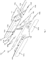
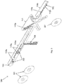
- an electrode carrier 100 comprising a substrate 101 made of a flexible material.
- the substrate 101 can for example be manufactured from a flexible plastic or polymer material having insulating properties.
- the material of the substrate 101 is preferable inextendible.
- the substrate can be made of a polyester film.
- Preferably the polyester film is a bi-axial oriented film having minimal elasticity in the longitudinal direction of the electrode carrier 100.
- the substrate 101 preferably has resilient properties to allow for bending and warping.
- the substrate 101 has inextendible sections 110a, 110b connected with an extendible section 111.
- the extendible section 111 is shown in fig. 1 having members 113 connected in parallel and in series in an X-shape.
- a conducting layer 102 can be provided having contact pads 112a, 112b mutually disposed on the inextendible sections 110a, 110b of the substrate 101 opposite of the extendible section 111.
- the conducting layer 102 can be made from metal, such as copper or silver, or conducting ink or conductive polymer.
- the conductive layer is made from a conductive coating containing silver.
- the contact pads 112a, 112b are electronically connectable via conductive tracks 113a, 113b, 113c to a connector which can be provided on a connection section 109 of the substrate.
- the conductive tracks 113a, 113b, 113c extend from the contact pads 112a to the connection section 109 of the substrate 101.
- the conductive track 113b corresponding to contact pad 112b passes a warpable member of the extendible section 111 to the connection section 109.
- a connector for electrically connecting the electrode carrier 102 to processing equipment may be provided on the connection section 109 of the substrate.
- the conductive tracks 113a, 113b, 113c can also be connected to a signal processor disposed anywhere on the substrate 101, for example on connection section 109.
- connection section can extend from for example the inextendible section having two contact pads, however it may be provided at for example one end of the short inextendible section facing the X-shaped extendible section.
- the contact pads 112a, 112b can be provided with an electrode lining 103a, 103b, which is designed to have a shape corresponding to the shape of the contact pads 112a, 112b respectively.
- the electrode lining 103a, 103b can comprise one or more layers to establish contact between the subject's skin and the contact pads.
- the electrode lining 103a, 103b can comprise a conductive coating, such as silver-silver chloride (Ag/AgCI) coating, which can be provided as a screen-printed layer which may be matched with a component such as carbon to form a dry electrode.
- a conductive coating such as silver-silver chloride (Ag/AgCI) coating
- the electrode lining 103a, 103b can also be formed by an AgCI solution or any other suitable electrolyte in an absorber which can be applied to the contact pads 112a, 112b to form wet electrodes.
- the electrode lining 103a, 103b can be formed by a conductive hydrogel, also to form a wet electrode.
- the hydrogel lining can be provided with an adhesive component, thereby allowing the contact pad and lining, thus forming the electrode, to be attached to the subject's skin.
- an insulating layer 104 can be applied having openings for exposing the contact pads 112a, 112b.
- conductive adhesive patches 105a can be applied.
- the adhesive patches 105a, 105b allow the electrode carrier 100 to be fixed to a subject's skin. Additional adhesive patches 106 can be provided for enhancing and strengthening the fixation of the electrode carrier 100 to the subject skin.
- the adhesive patches 105a, 105b, 106 can be covered by a peel-off cover layer 107a, 107b. These peel-off cover layers 107a, 107b can be removed shortly before use on a subject.
- An electromagnetic shielding layer can be arranged on top of the insulating layer covering the conductive tracks.
- the electromagnetic shielding layer can be arranged on the substrate at the side opposite of the contact pads.
- the electromagnetic shielding layer can be made from a conductive material such as a metal or from a conductive polymer.
- the electromagnetic shielding layer can be connected to one of the conductive tracks 113a, 113b, 113c which can be connected to electrical earth. The connection can be made using one or more vias penetrating through the insulating layer or the substrate.
- the signal processor can be provided with one or more amplifiers for amplifying the signals from the contact pads, and an analog to digital converter to capture and digitize the signals from the contact pads.
- the signal processor can be provided with a memory and program instructions for processing the digitized signal from the contact pads. The processing may comprise filtering such as applying a bandwidth filter, and analyzing the signals for the detection of patterns required for the measurement or monitoring.
- the signal processor can be a microprocessor or microcontroller, or a dedicated high performance signal processor.
- the signal processor and supporting circuitry can be integrated in or on the electrode carrier on at least one of the inextendible parts of the carrier.
- the processor can output its processed signal to the connector described above, thus allowing a digital connection to further signal and data processing.
- the signal; processor in the wired set up may be supplied from the connector, which is in turn connected to the further signal and data processing equipment.
- the electrode carrier may be also provided with a battery integrated or attached to the substrate.
- the processor can output its processed signal to a wireless communication device which can be arranged for wirelessly communicating the captured and/or processed signals from the contact pads using for example Bluetooth or wireless LAN or near field communication technology.
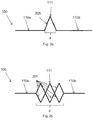
- a schematic view of an electrode carrier 100 is shown having an inextendible section 110a connected via an extendible section 111 to another inextendible section 110b.
- the extendible section 111 comprises one or more V-shaped member portions 201 of the substrate.
- the substrate is made of a resilient, flexible material, thus the V-shaped portion 201 is thereby warpable, by twisting or bending. This allows the inextendible sections 110a, 110b to have a variable mutual distance d.
- the electrode carrier 100 in the example of fig. 2a has a single member 201.
- Multiple warpable members 201 can form an extendible section 111.
- the warpable members 201 can be connected between the inextendible sections 110a, 110b in series and/or in parallel.
- the extendible section 111 of the example of fig. 2b has six warpable members 201, pairwise connected in parallel, and the pairs of parallel connected members connected in series to the inextendible sections 110a, 110b.
- the warpable members 201 in fig. 2b are shown mutually interconnected, forming cross connections between the members.
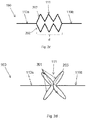
- an electrode carrier is shown having two strings 202 of warpable members 201 in series, wherein the respective strings 202 are mutually connected in parallel between the inextendible sections 110a, 110b.
- each warpable member 201 has a loop shape, which loops are connected on one side to the inextendible sections 110a, or 110b respectively and wherein the opposite end of the loops are interconnected by crossbar 203 as an interconnection member.
- the loop shaped warpable members 201 provide a longer stretch margin than the straight V-shaped members 201 of figures 2a - 2c .
- the cross bar 203 enhances transverse angular stability between the inextendible sections 110a, 110b.
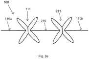
- a variant of the electrode carrier of fig. 2d is shown having two extendible sections 111, 211 interconnected by an inextendible section 210.
- the number of inextendible and extendible sections can vary depending on specific requirements regarding placement of electrodes and stretch.
- an electrode carrier 300 is shown having inextendible sections 110a, 110b and an extendible section 111.
- the contact pads 112a, 112b can be provided with a conductive connection to which replaceable electrodes can be pressed in a mechanical snap-fit and electrical connection.
- the contact pads 112a, in fig. 3 conduct the electrical signals from the replaceable electrodes via the conductive tracks 113a to the connection section 109 of the substrate 101.
- connection buttons 302 are provided on the contact pads 112a.
- the buttons 302 are provided with a conductive material and are attached to the contact pads 112a for example by a conductive adhesive or by stapling.
- the connection buttons 302 have an opening for receiving replaceable electrodes 301.
- the replaceable electrodes 301 can be provided with conductive protrusions which correspond with the openings in the connection buttons 302 for mechanically and electrically connecting the electrodes.
- the contact pads 112a, 112b can be provided with a conductive lug or protrusion on which a replaceable electrode 301 having a corresponding conductive button 302 can be pressed for making the mechanical and electrical connection.
- a replaceable electrode 301 to the electrode carrier 300 as shown in fig. 3 .
- the inextendible section 110b is shown having a contact pad 112b without button, and connected to the connection section via conductive tracks 113c and 113b, thereby prepared for receiving a wet or dry, or (hydro)gel electrode lining as set out above.
Claims (15)
- Support d'électrode destiné à une mesure électrophysiologique comprenant :• un substrat flexible ;• une pluralité de plages de contact fixé à la surface du substrat, dans lequel chaque plage de contact comprend des moyens conducteurs permettant de recevoir une électrode pour une mesure électrophysiologique ;• un premier moyen de raccordement fixé au substrat permettant de connecter de manière communicative les plages de contact à un dispositif de traitement de signal ; dans lequel• les premiers moyens de raccordement comprennent une pluralité de pistes conductrices situées sur la surface de substrat permettant une connexion électrique de la pluralité des plages de contact, dans lequel chaque piste conductrice correspond à au moins une plage de contact ; dans lequel• le substrat ayant au moins deux sections inextensibles permettant de recevoir les plages de contact ;• dans lequel les au moins deux sections inextensibles sont interconnectées au moyen d'une section extensible ; dans lequel• chaque section extensible comprend au moins un élément acceptant le gauchissement de matériau flexible ; dans lequel• au moins l'un des éléments acceptant le gauchissement reçoit au moins l'une des pistes conductrices ;• dans lequel l'au moins un élément acceptant le gauchissement comprend une partie en forme de V du substrat,caractérisé par• la section extensible comprend quatre éléments acceptant le gauchissement ayant chacun une partie en forme de V, lesdits quatre éléments acceptant le gauchissement sont disposés en forme de X ; dans lequel• les quatre éléments acceptant le gauchissement sont groupés en deux chaînes connectées en parallèle de deux éléments acceptant le gauchissement, dans lequel une partie centrale des deux éléments acceptant le gauchissement connectés en série sont interconnectés en utilisant un élément d'interconnexion.
- Support d'électrode selon la revendication 1, dans lequel le substrat est formé à partir d'une seule feuille de matériau flexible.
- Support d'électrode selon l'une quelconque des revendications précédentes, dans lequel au moins une des sections inextensibles du substrat est munie de deux plages de contact et dans lequel au moins une autre section inextensible du substrat est munie d'une seule plage de contact, dans lequel les plages de contact sont équipées de seconds moyens de raccordement permettant de fixer une électrode amovible destinée à une mesure électrophysiologique.
- Support d'électrode selon l'une quelconque des revendications précédentes, dans lequel au moins une des plages de contact comprend un ou plusieurs revêtements d'électrode destinés à une mesure électrophysiologique.
- Support d'électrode selon la revendication 4, dans lequel l'au moins une plage de contact est munie d'un revêtement d'électrode sèche ou d'un revêtement d'électrode humide.
- Support d'électrode selon la revendication 4, dans lequel au moins une plage de contact comprend le revêtement gel conducteur ou hydrogel.
- Support d'électrode selon la revendication 6, dans lequel le revêtement gel conducteur ou hydrogel comprend un matériau adhésif ou dans lequel l'un parmi le gel conducteur et l'hydrogel est adhésif et/ou a une forte adhérence.
- Support d'électrode selon l'une quelconque des revendications 4 à 7, dans lequel l'au moins une plage de contact comporte une couche adhésive environnante munie d'une ouverture afin d'exposer le revêtement d'électrode.
- Support d'électrode selon l'une quelconque des revendications 4 à 7, comprenant en outre une couche conductrice adhésive recouvrant au moins un revêtement d'électrode.
- Support d'électrode selon l'une quelconque des revendications 8 à 9, dans lequel la couche adhésive est recouverte d'une couche de recouvrement amovible.
- Support d'électrode selon l'une quelconque des revendications précédentes, dans lequel les pistes conductrices comprennent un matériau conducteur choisi parmi au moins un métal, un matériau en plastique conducteur et une encre contenant un métal, dans lequel les pistes conductrices sont au moins partiellement recouvertes d'une couche d'isolation.
- Support d'électrode selon l'une quelconque des revendications précédentes, dans lequel le support d'électrode est recouvert d'une couche de protection électromagnétique, dans lequel la couche de protection électromagnétique est connectée à l'une quelconque des pistes conductrices.
- Support d'électrode selon l'une quelconque des revendications précédentes, dans lequel les premiers moyens de raccordement comprennent un connecteur ayant des bornes, la borne étant reliée de manière électrique aux pistes conductrices, dans lequel les premiers moyens de raccordement comprennent des moyens de traitement de signal reliés aux pistes conductrices, dans lequel les moyens de traitement de signal comprennent des moyens permettant de capturer et de traiter des signaux électriques provenant des plages de contact.
- Support d'électrode selon la revendication 13, dans lequel les moyens de traitement de signal comprennent une sortie reliée au connecteur.
- Support d'électrode selon la revendication 13, dans lequel les premiers moyens de raccordement comprennent en outre un dispositif de transfert de données sans fil, relié de manière communicative au processeur de signal, dans lequel le dispositif de transfert de données sans fil est agencé pour transférer sans fil les signaux électriques capturés et/ou les données dérivées des signaux électriques capturés au dispositif de traitement de signal.
Applications Claiming Priority (2)
| Application Number | Priority Date | Filing Date | Title |
|---|---|---|---|
| NL2018031 | 2016-12-21 | ||
| PCT/EP2017/084215 WO2018115349A1 (fr) | 2016-12-21 | 2017-12-21 | Support d'électrode pour mesure électrophysiologique |
Publications (2)
| Publication Number | Publication Date |
|---|---|
| EP3558095A1 EP3558095A1 (fr) | 2019-10-30 |
| EP3558095B1 true EP3558095B1 (fr) | 2020-10-21 |
Family
ID=60943007
Family Applications (1)
| Application Number | Title | Priority Date | Filing Date |
|---|---|---|---|
| EP17826237.4A Active EP3558095B1 (fr) | 2016-12-21 | 2017-12-21 | Support d'électrode pour mesure électrophysiologique |
Country Status (6)
| Country | Link |
|---|---|
| US (1) | US11375937B2 (fr) |
| EP (1) | EP3558095B1 (fr) |
| JP (1) | JP7097891B2 (fr) |
| DK (1) | DK3558095T3 (fr) |
| ES (1) | ES2836506T3 (fr) |
| WO (1) | WO2018115349A1 (fr) |
Families Citing this family (6)
| Publication number | Priority date | Publication date | Assignee | Title |
|---|---|---|---|---|
| US10953192B2 (en) | 2017-05-18 | 2021-03-23 | Advanced Brain Monitoring, Inc. | Systems and methods for detecting and managing physiological patterns |
| EP3626158B1 (fr) | 2018-09-21 | 2023-03-15 | SmartMedics Sp. z o.o. | Patch d'électrode à plusieurs points de mesure |
| US20230051708A1 (en) * | 2021-08-11 | 2023-02-16 | Spes Medica Srl | Electrode support device for the registration of electroencephalografic signals |
| IT202100021785A1 (it) * | 2021-08-11 | 2023-02-11 | Spes Medica S P A | Dispositivo di supporto di elettrodi per la registrazione di segnali elettroencefalografici |
| DE102021209778A1 (de) * | 2021-09-06 | 2023-03-09 | Fraunhofer-Gesellschaft zur Förderung der angewandten Forschung eingetragener Verein | Elektrodenanordnung zur Messung von Biopotentialen an einem Kopf eines Menschen |
| WO2023097014A1 (fr) * | 2021-11-23 | 2023-06-01 | Cogwear, Inc. | Améliorations d'électrode et de biocapteur souples |
Family Cites Families (16)
| Publication number | Priority date | Publication date | Assignee | Title |
|---|---|---|---|---|
| JPH058967Y2 (fr) * | 1988-10-05 | 1993-03-05 | ||
| US6434410B1 (en) * | 1998-06-19 | 2002-08-13 | Aspect Medical Systems, Inc. | Electrode for measuring electrophysiological signals using liquid electrolytic gel with a high salt concentration |
| MXPA03000499A (es) | 2000-07-18 | 2003-06-24 | Motorola Inc | Sistema y metodo de electrocardiografia inalambrica. |
| WO2002022010A1 (fr) * | 2000-09-12 | 2002-03-21 | Nexan Limited | Bande de capteurs jetable dotee d'une pellicule d'alignement amoviblepour le controle des signes vitaux |
| US7933642B2 (en) * | 2001-07-17 | 2011-04-26 | Rud Istvan | Wireless ECG system |
| US7206630B1 (en) * | 2004-06-29 | 2007-04-17 | Cleveland Medical Devices, Inc | Electrode patch and wireless physiological measurement system and method |
| US7616980B2 (en) | 2006-05-08 | 2009-11-10 | Tyco Healthcare Group Lp | Radial electrode array |
| EP2109397B1 (fr) * | 2007-01-25 | 2020-02-19 | LifeSync Corporation | Ensemble radiotransparent connectable à une électrode ou un capteur |
| US8527028B2 (en) * | 2007-05-16 | 2013-09-03 | Medicomp, Inc. | Harness with sensors |
| WO2009134826A1 (fr) * | 2008-05-01 | 2009-11-05 | 3M Innovative Properties Company | Système de détecteur biomédical |
| US8818478B2 (en) * | 2011-03-31 | 2014-08-26 | Adidas Ag | Sensor garment |
| JP6181356B2 (ja) | 2012-06-28 | 2017-08-16 | 株式会社アイ・メデックス | 生体電極用パッド |
| US11033235B2 (en) * | 2013-06-19 | 2021-06-15 | Nimbleheart Inc. | Method and apparatus for motion artifact reduction in ECG harness |
| GB2521342B (en) * | 2013-10-17 | 2016-08-03 | Monica Healthcare Ltd | Apparatus and method for detecting an abdominal electrophysiological signal |
| CN107073260B (zh) | 2014-09-17 | 2021-05-28 | 纽洛利夫有限公司 | 用于神经刺激和身体参数的感测的头戴式装置 |
| US10925540B2 (en) * | 2016-08-18 | 2021-02-23 | MAD Apparel, Inc. | Garment with conductive thread exposed on both sides |
-
2017
- 2017-12-21 ES ES17826237T patent/ES2836506T3/es active Active
- 2017-12-21 EP EP17826237.4A patent/EP3558095B1/fr active Active
- 2017-12-21 US US16/472,312 patent/US11375937B2/en active Active
- 2017-12-21 WO PCT/EP2017/084215 patent/WO2018115349A1/fr active Search and Examination
- 2017-12-21 DK DK17826237.4T patent/DK3558095T3/da active
- 2017-12-21 JP JP2019534873A patent/JP7097891B2/ja active Active
Non-Patent Citations (1)
| Title |
|---|
| None * |
Also Published As
| Publication number | Publication date |
|---|---|
| DK3558095T3 (da) | 2021-01-18 |
| US11375937B2 (en) | 2022-07-05 |
| JP2020513910A (ja) | 2020-05-21 |
| WO2018115349A1 (fr) | 2018-06-28 |
| JP7097891B2 (ja) | 2022-07-08 |
| US20200383594A1 (en) | 2020-12-10 |
| EP3558095A1 (fr) | 2019-10-30 |
| ES2836506T3 (es) | 2021-06-25 |
Similar Documents
| Publication | Publication Date | Title |
|---|---|---|
| EP3558095B1 (fr) | Support d'électrode pour mesure électrophysiologique | |
| US10624552B2 (en) | Method for constructing physiological electrode assembly with integrated flexile wire components | |
| US10631748B2 (en) | Extended wear electrocardiography patch with wire interconnects | |
| US10939841B2 (en) | Wearable electrocardiography and physiology monitoring ensemble | |
| KR102582824B1 (ko) | 사용자의 근전도 신호 측정용 휴대용 장치, 시스템 및 방법 | |
| US8548558B2 (en) | Electrode capable of attachment to a garment, system, and methods of manufacturing | |
| EP3626158B1 (fr) | Patch d'électrode à plusieurs points de mesure | |
| KR20170009823A (ko) | 생리학적 모니터링 의복들 | |
| WO1999040844A1 (fr) | Dispositif universel de positionnement d'un capteur d'electrocardiogramme et procede associe | |
| JP5767434B2 (ja) | 患者監視装置用の電極セット | |
| KR101384761B1 (ko) | 호흡과 심전도의 동시 측정이 가능한 스포츠 브라 | |
| WO2003051195A1 (fr) | Dispositif universel de positionnement d'electrodes d'ecg pour quatre tailles dont extra-large, et procede associe | |
| US20210128042A1 (en) | System for capturing biosignals | |
| WO2017026796A1 (fr) | Capteur d'électrocardiogramme de type patch | |
| EP3048963B1 (fr) | Timbre d'électrocardiographie à utilisation prolongée utilisant des fils-électrodes entrelacés | |
| JP2020188895A (ja) | 心電シート、心電測定電極ユニット、心電電極選択評価回路、心電シートの使用方法及び心電シートの製造方法 | |
| EP4287949A1 (fr) | Électrodes sérigraphiées destinées à un article pour électrocardiogramme | |
| KR101271286B1 (ko) | 방사선 투과가 가능한 생체정보 측정장치 | |
| JP2018094206A (ja) | ウェアラブルデバイス |
Legal Events
| Date | Code | Title | Description |
|---|---|---|---|
| STAA | Information on the status of an ep patent application or granted ep patent |
Free format text: STATUS: UNKNOWN |
|
| STAA | Information on the status of an ep patent application or granted ep patent |
Free format text: STATUS: THE INTERNATIONAL PUBLICATION HAS BEEN MADE |
|
| PUAI | Public reference made under article 153(3) epc to a published international application that has entered the european phase |
Free format text: ORIGINAL CODE: 0009012 |
|
| STAA | Information on the status of an ep patent application or granted ep patent |
Free format text: STATUS: REQUEST FOR EXAMINATION WAS MADE |
|
| 17P | Request for examination filed |
Effective date: 20190626 |
|
| AK | Designated contracting states |
Kind code of ref document: A1 Designated state(s): AL AT BE BG CH CY CZ DE DK EE ES FI FR GB GR HR HU IE IS IT LI LT LU LV MC MK MT NL NO PL PT RO RS SE SI SK SM TR |
|
| AX | Request for extension of the european patent |
Extension state: BA ME |
|
| DAV | Request for validation of the european patent (deleted) | ||
| DAX | Request for extension of the european patent (deleted) | ||
| GRAP | Despatch of communication of intention to grant a patent |
Free format text: ORIGINAL CODE: EPIDOSNIGR1 |
|
| STAA | Information on the status of an ep patent application or granted ep patent |
Free format text: STATUS: GRANT OF PATENT IS INTENDED |
|
| INTG | Intention to grant announced |
Effective date: 20200727 |
|
| GRAS | Grant fee paid |
Free format text: ORIGINAL CODE: EPIDOSNIGR3 |
|
| GRAA | (expected) grant |
Free format text: ORIGINAL CODE: 0009210 |
|
| STAA | Information on the status of an ep patent application or granted ep patent |
Free format text: STATUS: THE PATENT HAS BEEN GRANTED |
|
| AK | Designated contracting states |
Kind code of ref document: B1 Designated state(s): AL AT BE BG CH CY CZ DE DK EE ES FI FR GB GR HR HU IE IS IT LI LT LU LV MC MK MT NL NO PL PT RO RS SE SI SK SM TR |
|
| REG | Reference to a national code |
Ref country code: GB Ref legal event code: FG4D |
|
| REG | Reference to a national code |
Ref country code: CH Ref legal event code: EP |
|
| REG | Reference to a national code |
Ref country code: IE Ref legal event code: FG4D |
|
| REG | Reference to a national code |
Ref country code: DE Ref legal event code: R096 Ref document number: 602017026080 Country of ref document: DE |
|
| REG | Reference to a national code |
Ref country code: AT Ref legal event code: REF Ref document number: 1324973 Country of ref document: AT Kind code of ref document: T Effective date: 20201115 |
|
| REG | Reference to a national code |
Ref country code: FI Ref legal event code: FGE |
|
| REG | Reference to a national code |
Ref country code: NL Ref legal event code: FP |
|
| REG | Reference to a national code |
Ref country code: DK Ref legal event code: T3 Effective date: 20210111 |
|
| REG | Reference to a national code |
Ref country code: SE Ref legal event code: TRGR |
|
| REG | Reference to a national code |
Ref country code: NO Ref legal event code: T2 Effective date: 20201021 |
|
| PG25 | Lapsed in a contracting state [announced via postgrant information from national office to epo] |
Ref country code: RS Free format text: LAPSE BECAUSE OF FAILURE TO SUBMIT A TRANSLATION OF THE DESCRIPTION OR TO PAY THE FEE WITHIN THE PRESCRIBED TIME-LIMIT Effective date: 20201021 Ref country code: PT Free format text: LAPSE BECAUSE OF FAILURE TO SUBMIT A TRANSLATION OF THE DESCRIPTION OR TO PAY THE FEE WITHIN THE PRESCRIBED TIME-LIMIT Effective date: 20210222 Ref country code: GR Free format text: LAPSE BECAUSE OF FAILURE TO SUBMIT A TRANSLATION OF THE DESCRIPTION OR TO PAY THE FEE WITHIN THE PRESCRIBED TIME-LIMIT Effective date: 20210122 |
|
| REG | Reference to a national code |
Ref country code: LT Ref legal event code: MG4D |
|
| PG25 | Lapsed in a contracting state [announced via postgrant information from national office to epo] |
Ref country code: IS Free format text: LAPSE BECAUSE OF FAILURE TO SUBMIT A TRANSLATION OF THE DESCRIPTION OR TO PAY THE FEE WITHIN THE PRESCRIBED TIME-LIMIT Effective date: 20210221 Ref country code: LV Free format text: LAPSE BECAUSE OF FAILURE TO SUBMIT A TRANSLATION OF THE DESCRIPTION OR TO PAY THE FEE WITHIN THE PRESCRIBED TIME-LIMIT Effective date: 20201021 Ref country code: PL Free format text: LAPSE BECAUSE OF FAILURE TO SUBMIT A TRANSLATION OF THE DESCRIPTION OR TO PAY THE FEE WITHIN THE PRESCRIBED TIME-LIMIT Effective date: 20201021 Ref country code: BG Free format text: LAPSE BECAUSE OF FAILURE TO SUBMIT A TRANSLATION OF THE DESCRIPTION OR TO PAY THE FEE WITHIN THE PRESCRIBED TIME-LIMIT Effective date: 20210121 |
|
| REG | Reference to a national code |
Ref country code: ES Ref legal event code: FG2A Ref document number: 2836506 Country of ref document: ES Kind code of ref document: T3 Effective date: 20210625 |
|
| PG25 | Lapsed in a contracting state [announced via postgrant information from national office to epo] |
Ref country code: HR Free format text: LAPSE BECAUSE OF FAILURE TO SUBMIT A TRANSLATION OF THE DESCRIPTION OR TO PAY THE FEE WITHIN THE PRESCRIBED TIME-LIMIT Effective date: 20201021 |
|
| REG | Reference to a national code |
Ref country code: DE Ref legal event code: R097 Ref document number: 602017026080 Country of ref document: DE |
|
| PG25 | Lapsed in a contracting state [announced via postgrant information from national office to epo] |
Ref country code: RO Free format text: LAPSE BECAUSE OF FAILURE TO SUBMIT A TRANSLATION OF THE DESCRIPTION OR TO PAY THE FEE WITHIN THE PRESCRIBED TIME-LIMIT Effective date: 20201021 Ref country code: SK Free format text: LAPSE BECAUSE OF FAILURE TO SUBMIT A TRANSLATION OF THE DESCRIPTION OR TO PAY THE FEE WITHIN THE PRESCRIBED TIME-LIMIT Effective date: 20201021 Ref country code: SM Free format text: LAPSE BECAUSE OF FAILURE TO SUBMIT A TRANSLATION OF THE DESCRIPTION OR TO PAY THE FEE WITHIN THE PRESCRIBED TIME-LIMIT Effective date: 20201021 Ref country code: CZ Free format text: LAPSE BECAUSE OF FAILURE TO SUBMIT A TRANSLATION OF THE DESCRIPTION OR TO PAY THE FEE WITHIN THE PRESCRIBED TIME-LIMIT Effective date: 20201021 Ref country code: EE Free format text: LAPSE BECAUSE OF FAILURE TO SUBMIT A TRANSLATION OF THE DESCRIPTION OR TO PAY THE FEE WITHIN THE PRESCRIBED TIME-LIMIT Effective date: 20201021 Ref country code: LT Free format text: LAPSE BECAUSE OF FAILURE TO SUBMIT A TRANSLATION OF THE DESCRIPTION OR TO PAY THE FEE WITHIN THE PRESCRIBED TIME-LIMIT Effective date: 20201021 |
|
| PLBE | No opposition filed within time limit |
Free format text: ORIGINAL CODE: 0009261 |
|
| STAA | Information on the status of an ep patent application or granted ep patent |
Free format text: STATUS: NO OPPOSITION FILED WITHIN TIME LIMIT |
|
| PG25 | Lapsed in a contracting state [announced via postgrant information from national office to epo] |
Ref country code: MC Free format text: LAPSE BECAUSE OF FAILURE TO SUBMIT A TRANSLATION OF THE DESCRIPTION OR TO PAY THE FEE WITHIN THE PRESCRIBED TIME-LIMIT Effective date: 20201021 |
|
| 26N | No opposition filed |
Effective date: 20210722 |
|
| PG25 | Lapsed in a contracting state [announced via postgrant information from national office to epo] |
Ref country code: AL Free format text: LAPSE BECAUSE OF FAILURE TO SUBMIT A TRANSLATION OF THE DESCRIPTION OR TO PAY THE FEE WITHIN THE PRESCRIBED TIME-LIMIT Effective date: 20201021 |
|
| PG25 | Lapsed in a contracting state [announced via postgrant information from national office to epo] |
Ref country code: SI Free format text: LAPSE BECAUSE OF FAILURE TO SUBMIT A TRANSLATION OF THE DESCRIPTION OR TO PAY THE FEE WITHIN THE PRESCRIBED TIME-LIMIT Effective date: 20201021 |
|
| PG25 | Lapsed in a contracting state [announced via postgrant information from national office to epo] |
Ref country code: IS Free format text: LAPSE BECAUSE OF FAILURE TO SUBMIT A TRANSLATION OF THE DESCRIPTION OR TO PAY THE FEE WITHIN THE PRESCRIBED TIME-LIMIT Effective date: 20210221 Ref country code: TR Free format text: LAPSE BECAUSE OF FAILURE TO SUBMIT A TRANSLATION OF THE DESCRIPTION OR TO PAY THE FEE WITHIN THE PRESCRIBED TIME-LIMIT Effective date: 20201021 Ref country code: MT Free format text: LAPSE BECAUSE OF FAILURE TO SUBMIT A TRANSLATION OF THE DESCRIPTION OR TO PAY THE FEE WITHIN THE PRESCRIBED TIME-LIMIT Effective date: 20201021 Ref country code: CY Free format text: LAPSE BECAUSE OF FAILURE TO SUBMIT A TRANSLATION OF THE DESCRIPTION OR TO PAY THE FEE WITHIN THE PRESCRIBED TIME-LIMIT Effective date: 20201021 |
|
| PG25 | Lapsed in a contracting state [announced via postgrant information from national office to epo] |
Ref country code: MK Free format text: LAPSE BECAUSE OF FAILURE TO SUBMIT A TRANSLATION OF THE DESCRIPTION OR TO PAY THE FEE WITHIN THE PRESCRIBED TIME-LIMIT Effective date: 20201021 |
|
| REG | Reference to a national code |
Ref country code: AT Ref legal event code: UEP Ref document number: 1324973 Country of ref document: AT Kind code of ref document: T Effective date: 20201021 |
|
| PGFP | Annual fee paid to national office [announced via postgrant information from national office to epo] |
Ref country code: BE Payment date: 20221118 Year of fee payment: 6 |
|
| PGFP | Annual fee paid to national office [announced via postgrant information from national office to epo] |
Ref country code: ES Payment date: 20230113 Year of fee payment: 6 Ref country code: CH Payment date: 20230101 Year of fee payment: 6 |
|
| PGFP | Annual fee paid to national office [announced via postgrant information from national office to epo] |
Ref country code: NL Payment date: 20231116 Year of fee payment: 7 |
|
| PGFP | Annual fee paid to national office [announced via postgrant information from national office to epo] |
Ref country code: GB Payment date: 20231102 Year of fee payment: 7 |
|
| PGFP | Annual fee paid to national office [announced via postgrant information from national office to epo] |
Ref country code: SE Payment date: 20231110 Year of fee payment: 7 Ref country code: NO Payment date: 20231212 Year of fee payment: 7 Ref country code: LU Payment date: 20231214 Year of fee payment: 7 Ref country code: IT Payment date: 20231110 Year of fee payment: 7 Ref country code: IE Payment date: 20231109 Year of fee payment: 7 Ref country code: FR Payment date: 20231108 Year of fee payment: 7 Ref country code: FI Payment date: 20231219 Year of fee payment: 7 Ref country code: DK Payment date: 20231214 Year of fee payment: 7 Ref country code: DE Payment date: 20231031 Year of fee payment: 7 Ref country code: AT Payment date: 20231127 Year of fee payment: 7 |
|
| PGFP | Annual fee paid to national office [announced via postgrant information from national office to epo] |
Ref country code: BE Payment date: 20231121 Year of fee payment: 7 |
|
| PGFP | Annual fee paid to national office [announced via postgrant information from national office to epo] |
Ref country code: ES Payment date: 20240118 Year of fee payment: 7 |