EP2109397B1 - Ensemble radiotransparent connectable à une électrode ou un capteur - Google Patents
Ensemble radiotransparent connectable à une électrode ou un capteur Download PDFInfo
- Publication number
- EP2109397B1 EP2109397B1 EP08728309.9A EP08728309A EP2109397B1 EP 2109397 B1 EP2109397 B1 EP 2109397B1 EP 08728309 A EP08728309 A EP 08728309A EP 2109397 B1 EP2109397 B1 EP 2109397B1
- Authority
- EP
- European Patent Office
- Prior art keywords
- assembly
- electrode
- chest
- radiolucent
- sensor
- Prior art date
- Legal status (The legal status is an assumption and is not a legal conclusion. Google has not performed a legal analysis and makes no representation as to the accuracy of the status listed.)
- Active
Links
- 0 C1CC=*CC1 Chemical compound C1CC=*CC1 0.000 description 2
Images


Classifications
-
- A—HUMAN NECESSITIES
- A61—MEDICAL OR VETERINARY SCIENCE; HYGIENE
- A61B—DIAGNOSIS; SURGERY; IDENTIFICATION
- A61B5/00—Measuring for diagnostic purposes; Identification of persons
- A61B5/24—Detecting, measuring or recording bioelectric or biomagnetic signals of the body or parts thereof
- A61B5/25—Bioelectric electrodes therefor
- A61B5/271—Arrangements of electrodes with cords, cables or leads, e.g. single leads or patient cord assemblies
- A61B5/273—Connection of cords, cables or leads to electrodes
- A61B5/274—Connection of cords, cables or leads to electrodes using snap or button fasteners
-
- A—HUMAN NECESSITIES
- A61—MEDICAL OR VETERINARY SCIENCE; HYGIENE
- A61B—DIAGNOSIS; SURGERY; IDENTIFICATION
- A61B5/00—Measuring for diagnostic purposes; Identification of persons
- A61B5/24—Detecting, measuring or recording bioelectric or biomagnetic signals of the body or parts thereof
- A61B5/25—Bioelectric electrodes therefor
- A61B5/251—Means for maintaining electrode contact with the body
- A61B5/257—Means for maintaining electrode contact with the body using adhesive means, e.g. adhesive pads or tapes
- A61B5/259—Means for maintaining electrode contact with the body using adhesive means, e.g. adhesive pads or tapes using conductive adhesive means, e.g. gels
-
- A—HUMAN NECESSITIES
- A61—MEDICAL OR VETERINARY SCIENCE; HYGIENE
- A61B—DIAGNOSIS; SURGERY; IDENTIFICATION
- A61B5/00—Measuring for diagnostic purposes; Identification of persons
- A61B5/24—Detecting, measuring or recording bioelectric or biomagnetic signals of the body or parts thereof
- A61B5/25—Bioelectric electrodes therefor
- A61B5/276—Protection against electrode failure
-
- A—HUMAN NECESSITIES
- A61—MEDICAL OR VETERINARY SCIENCE; HYGIENE
- A61B—DIAGNOSIS; SURGERY; IDENTIFICATION
- A61B5/00—Measuring for diagnostic purposes; Identification of persons
- A61B5/24—Detecting, measuring or recording bioelectric or biomagnetic signals of the body or parts thereof
- A61B5/25—Bioelectric electrodes therefor
- A61B5/279—Bioelectric electrodes therefor specially adapted for particular uses
- A61B5/28—Bioelectric electrodes therefor specially adapted for particular uses for electrocardiography [ECG]
- A61B5/282—Holders for multiple electrodes
-
- A—HUMAN NECESSITIES
- A61—MEDICAL OR VETERINARY SCIENCE; HYGIENE
- A61B—DIAGNOSIS; SURGERY; IDENTIFICATION
- A61B5/00—Measuring for diagnostic purposes; Identification of persons
- A61B5/24—Detecting, measuring or recording bioelectric or biomagnetic signals of the body or parts thereof
- A61B5/25—Bioelectric electrodes therefor
- A61B5/279—Bioelectric electrodes therefor specially adapted for particular uses
- A61B5/291—Bioelectric electrodes therefor specially adapted for particular uses for electroencephalography [EEG]
-
- A—HUMAN NECESSITIES
- A61—MEDICAL OR VETERINARY SCIENCE; HYGIENE
- A61B—DIAGNOSIS; SURGERY; IDENTIFICATION
- A61B5/00—Measuring for diagnostic purposes; Identification of persons
- A61B5/24—Detecting, measuring or recording bioelectric or biomagnetic signals of the body or parts thereof
- A61B5/30—Input circuits therefor
- A61B5/303—Patient cord assembly, e.g. cable harness
-
- A—HUMAN NECESSITIES
- A61—MEDICAL OR VETERINARY SCIENCE; HYGIENE
- A61B—DIAGNOSIS; SURGERY; IDENTIFICATION
- A61B5/00—Measuring for diagnostic purposes; Identification of persons
- A61B5/68—Arrangements of detecting, measuring or recording means, e.g. sensors, in relation to patient
- A61B5/6801—Arrangements of detecting, measuring or recording means, e.g. sensors, in relation to patient specially adapted to be attached to or worn on the body surface
- A61B5/6813—Specially adapted to be attached to a specific body part
- A61B5/6822—Neck
-
- A—HUMAN NECESSITIES
- A61—MEDICAL OR VETERINARY SCIENCE; HYGIENE
- A61B—DIAGNOSIS; SURGERY; IDENTIFICATION
- A61B5/00—Measuring for diagnostic purposes; Identification of persons
- A61B5/68—Arrangements of detecting, measuring or recording means, e.g. sensors, in relation to patient
- A61B5/6801—Arrangements of detecting, measuring or recording means, e.g. sensors, in relation to patient specially adapted to be attached to or worn on the body surface
- A61B5/6813—Specially adapted to be attached to a specific body part
- A61B5/6823—Trunk, e.g., chest, back, abdomen, hip
-
- A—HUMAN NECESSITIES
- A61—MEDICAL OR VETERINARY SCIENCE; HYGIENE
- A61B—DIAGNOSIS; SURGERY; IDENTIFICATION
- A61B2560/00—Constructional details of operational features of apparatus; Accessories for medical measuring apparatus
- A61B2560/04—Constructional details of apparatus
- A61B2560/0443—Modular apparatus
- A61B2560/045—Modular apparatus with a separable interface unit, e.g. for communication
-
- A—HUMAN NECESSITIES
- A61—MEDICAL OR VETERINARY SCIENCE; HYGIENE
- A61B—DIAGNOSIS; SURGERY; IDENTIFICATION
- A61B2562/00—Details of sensors; Constructional details of sensor housings or probes; Accessories for sensors
- A61B2562/02—Details of sensors specially adapted for in-vivo measurements
- A61B2562/0209—Special features of electrodes classified in A61B5/24, A61B5/25, A61B5/283, A61B5/291, A61B5/296, A61B5/053
- A61B2562/0215—Silver or silver chloride containing
-
- A—HUMAN NECESSITIES
- A61—MEDICAL OR VETERINARY SCIENCE; HYGIENE
- A61B—DIAGNOSIS; SURGERY; IDENTIFICATION
- A61B2562/00—Details of sensors; Constructional details of sensor housings or probes; Accessories for sensors
- A61B2562/02—Details of sensors specially adapted for in-vivo measurements
- A61B2562/0285—Nanoscale sensors
-
- A—HUMAN NECESSITIES
- A61—MEDICAL OR VETERINARY SCIENCE; HYGIENE
- A61B—DIAGNOSIS; SURGERY; IDENTIFICATION
- A61B2562/00—Details of sensors; Constructional details of sensor housings or probes; Accessories for sensors
- A61B2562/16—Details of sensor housings or probes; Details of structural supports for sensors
- A61B2562/164—Details of sensor housings or probes; Details of structural supports for sensors the sensor is mounted in or on a conformable substrate or carrier
-
- A—HUMAN NECESSITIES
- A61—MEDICAL OR VETERINARY SCIENCE; HYGIENE
- A61B—DIAGNOSIS; SURGERY; IDENTIFICATION
- A61B2562/00—Details of sensors; Constructional details of sensor housings or probes; Accessories for sensors
- A61B2562/22—Arrangements of medical sensors with cables or leads; Connectors or couplings specifically adapted for medical sensors
- A61B2562/221—Arrangements of sensors with cables or leads, e.g. cable harnesses
- A61B2562/222—Electrical cables or leads therefor, e.g. coaxial cables or ribbon cables
-
- A—HUMAN NECESSITIES
- A61—MEDICAL OR VETERINARY SCIENCE; HYGIENE
- A61B—DIAGNOSIS; SURGERY; IDENTIFICATION
- A61B2562/00—Details of sensors; Constructional details of sensor housings or probes; Accessories for sensors
- A61B2562/22—Arrangements of medical sensors with cables or leads; Connectors or couplings specifically adapted for medical sensors
- A61B2562/225—Connectors or couplings
- A61B2562/226—Connectors or couplings comprising means for identifying the connector, e.g. to prevent incorrect connection to socket
-
- A—HUMAN NECESSITIES
- A61—MEDICAL OR VETERINARY SCIENCE; HYGIENE
- A61B—DIAGNOSIS; SURGERY; IDENTIFICATION
- A61B2562/00—Details of sensors; Constructional details of sensor housings or probes; Accessories for sensors
- A61B2562/22—Arrangements of medical sensors with cables or leads; Connectors or couplings specifically adapted for medical sensors
- A61B2562/225—Connectors or couplings
- A61B2562/227—Sensors with electrical connectors
Definitions
- the present invention relates to the monitoring of physiological data and to architectures having improved radiolucency for connecting flat printed circuits to sensors.
- the invention is defined by the independent claim.
- Preferred embodiments are defined by the dependent claims.
- the ability to monitor the physiological parameters of a live subject, and in particular a human patient, is crucial in determining the health status of the patient and the proper medical treatment to be applied to the patient, as well as in understanding the effects of certain variables on physiological processes while conducting research.
- physiological parameters such as heart rate and brain wave activity
- Measurement of these electrical signals has long been accomplished by applying electrically conductive sensors to the surface of the patient's skin or other tissues or by the invasive implantation of the sensor inside the patient's body.
- these detected or sensed electrical signals are then relayed to a separate monitoring device whereby the signals are processed and displayed in a useful form.
- an electrocardiograph (ECG) system monitors the electrical heart activity of a patient.
- ECG systems utilize electrodes or sensors which are placed on a patient's chest in specific locations to detect the electrical impulses generated by the heart during each beat.
- these electrical impulses or signals are directly transferred from each electrode or sensor to a nearby, stationary ECG monitor through individual lead wires or cables that are connected to each electrode or sensor.
- the ECG monitor performs various signal processing and computational operations to convert the raw electrical signals into meaningful information to be displayed or printed out for review by a physician.
- These systems generally require that the patient be tethered to a stationary monitor and remain sufficiently still in order that the electrodes and wire attachments are not disturbed. Restriction of the patient's movement is oftentimes cumbersome and uncomfortable for a patient and the attending medical staff. It is also ill-suited for emergency situations during which a patient's body must be rapidly moved to a variety of positions and transported to several locations.
- ECG signals In order to alleviate discomfort and to increase a patient's mobility, several portable telemetry systems exist for the monitoring of physiological parameters. Generally, two types of telemetry systems exist for the monitoring of ECG signals. One type of system requires placing conventional ECG electrodes on the skin surface of a patient and connecting the electrodes to a portable, patient-worn telemetry unit by one or more lead wires or cables. The telemetry unit wirelessly transmits the ECG signals to a remote monitoring device. Although the patient has greater mobility, there still exist some disadvantages. Because each electrode or sensor is individually connected to the telemetry unit by an individual lead wire or cable, the several lead wires or cables become confusingly intertwined making it difficult to make the proper corresponding connections between the electrodes and the telemetry unit.
- each electrode or sensor is placed separately on the patient, one at a time in a sequence, the chances of acquiring an inaccurate signal due to improper placement on the patient are high. Additionally, the motion of the individual current carrying lead wires in relation to each other causes the generation of electrical artifacts in the transmitted signal.
- the second type of wireless telemetry system eliminates all wires extending from the electrodes and replaces them with a self-contained strip or patch-like assembly which incorporates the electrodes and the lead wires.
- the strip or patch assembly is then adhered to the patient's skin or otherwise worn on the body.
- the assembly is comprised of a thin and flexible substrate constructed of non-conducting material with the electrodes or conductive areas intended to be in contact with the patient and fully integrated into the surface of the substrate that is in contact with the skin.
- the electrodes or conductive areas are fixed in set positions thereby greatly reducing the possibility of placing one or more of them improperly on the patient.
- One or more transmitters or transceivers and the corresponding circuitry are also integrated into the assembly's surface for wirelessly transmitting the detected ECG signals to a remote monitoring location.
- these types of fully-integrated electrode assemblies have several disadvantages stemming from their high cost and lack of flexibility in permitting alternative placement of the electrodes.
- ECG electrodes are relatively inexpensive and detachable from the lead wires so that they may be easily disposed of after each use in case of a failure or defect in the electrode and to maintain a relatively sterile environment that is necessary for medical use.
- fully-integrated electrode assemblies in order to dispose of a failed electrode or sensor element, the entire assembly must impractically be discarded. Also, the entire assembly, if not disposable, must be meticulously cleaned after each use or each patient.
- most electrodes require the application of aqueous silver chloride gel or hydrogel to the surface of the electrodes to increase their conductivity. These gels will rapidly dry out and lose their conductivity.
- the electrodes In order to preserve these gels after being pre-applied to the electrodes, the electrodes must be hermetically sealed when packaged. Thus, when the gels are applied to fully-integrated electrode assemblies, the entire assembly must be hermetically sealed for storage. Once opened, the assembly has no shelf life and must be used immediately or discarded.
- disposable chest assemblies that contain a plurality of fixed connections for connecting to separate, conventional electrodes or sensors have been developed.
- chest assemblies consist of a thin and flexible substrate constructed of non-conductive material that spans across the length of the chest.
- Printed onto or embedded within the substrate are conductive traces that run along its surface extending from the electrode connections to one or more common terminals or trunks.
- the terminal or trunk connects to a separate monitoring device such as a patient-worn telemetry unit that is attached to a more comfortable weight-bearing location on the body than the chest or is wired to a bedside monitor.
- electromagnetic diagnostic imaging devices including but not limited to x-rays, fluoroscopes, CAT scans and magnetic resonance imaging
- lead wires and electrode assemblies that are transparent to these imaging devices.
- the devices need to be configured and constructed to be sufficiently radiolucent and radiotransparent for medical treatment applications.
- Conventional wired and wireless ECG systems particularly those with chest-worn components, significantly interfere with the normal use and viewing of an X-ray film, fluoroscopic or other image that is created by electromagnetic radiation.
- Efforts have been made to improve the translucency or permeability to X-ray of the electrodes or sensors themselves by lessening the mass or density of the metallic parts used in their construction.
- a thin layer of metallic foil or conductive paint or ink has been used on the conductive surfaces of heart monitoring and stimulating electrodes.
- the overall surface area of the foil or painted area must be increased to provide the same amount of conductivity. Because the electrodes or sensors are normally being applied to the non-flat surface of a 3-dimensional object, they often need to be placed at an angle to the viewing plane of the diagnostic device.
- the metallic components of an electrode or sensor have been completely eliminated and replaced with one or more layers of thin, carbon or graphite-filled polymers, often in conjunction with conductive adhesives or gels.
- Lead wires that connect to the electrodes have also been substituted with cables of insulated, carbon fibers.
- these polymers are generally composed of very thin, carbon filaments or particles thereby having the characteristic of high impedance such that a large amount of external heat is generated by a flowing current.
- carbon based conductors alone will rarely withstand an external defibrillation current applied to the body.
- a thin coating of silver/silver chloride is applied to the surface of the carbon material.
- the application of the silver/silver chloride negatively affects the electrode's radiolucency and may make it opaque.
- carbon or graphite may be more radiolucent than a comparably sized metallic conductor
- carbon or graphite materials are less conductive than metals and therefore require a greater quantity of carbon or graphite to conduct the same amount of electricity as a metal counterpart.
- the carbon or graphite-filled polymers or cables are relatively thick in comparison making them relatively unwieldy when worn by a patient.
- the increased thickness of the materials reduces the radiolucency and shows up unsatisfactorily on the resulting images. This is particularly problematic with depth-capturing images such as computed tomography (CT) scans.
- CT computed tomography
- a conductive mesh backing made of low-resistance, non-corrosive and pliable metal wires is applied to a skin-contacting conductive polymer adhesive matrix or pad such that the open space of the mesh is greater than about 50%.
- a pattern of metal or otherwise conductive ink is applied to the surface of a conductive polymer sheet. The objective of the mesh or ink patterns is to provide enough conductive surface so that there is a low amount of electrical resistance for the conduction of high voltage defibrillation pulses without burning or generating a lot of heat, and remaining somewhat radiolucent.
- the amount of conductive surface required in these applications is substantially more than is required in an electrode that is simply used for monitoring.
- Neither of these applications addresses a radiolucent connection to an electrode or sensor that is electrically suitable for the initial acquisition of an electrical signal. Rather, they are only concerned with spreading a large amount of applied current on the backend of the circuit path along the skin surface.
- Described embodiments of the present invention relate to a radiolucent ECG electrode assembly that can be made universally compatible with existing or conventional ECG monitors and electrodes.
- the invention be limited to an ECG system as it has utility in any system that acquires physiological parameters from a patient using sensors and allows for the monitoring of physiological data.
- the ECG system generally comprises a lightweight, portable, radiolucent or radiotransparent chest assembly and a body electronics unit containing the electronic components required to acquire a signal from the electrodes and transmit the same wirelessly, and a base station for receiving the wireless signal.
- radiolucent is defined as being wholly or partially permeable to radiation so as to be translucent, transparent or nearly invisible in an X-ray so as not to unduly interfere with the appearance of or unacceptably impair the ability to detect physical abnormalities of an X-rayed subject by the normal use and viewing of an X-ray film.
- the chest assembly connects to separate electrodes which are intended to be placed at specific locations on the patient's body for detecting the electrical signals of the patient's heart; providing up to a "7-lead" analysis of the heart.
- the chest assembly can be augmented with a precordial assembly that connects to electrodes specifically located on the patient's body, thus providing a "12-lead" analysis of the heart.
- the electrical signals are transmitted through the chest assembly and/or the precordial assembly to any conventional ECG monitor (including any legacy ECG monitor) by way of an adapter.
- the electrical signals are transmitted wirelessly and the chest assembly and/or precordial assembly are connected to a body electronics unit, which is removably secured to the patient.
- the body electronics unit may be attached to the patient's arm using a releasable arm band.
- the body electronics unit transmits the electrical signals to the base station via radio transmission and may utilize two-way wireless communication protocols which are generally known in the art (e.g. BLUETOOTH® or WiFi®). Therefore, the wires that ordinarily tether a patient to an ECG monitor are conveniently replaced by a radio link.
- the base station contains terminals configured to attach to standard lead wires or cables and transmits the electrical signals to a conventional ECG monitor through these standard lead wires or cables.
- the ECG monitor then processes or transforms the electrical signals into meaningful information that can be reviewed or otherwise used by a physician.
- the present invention is capable of collecting and transmitting other physiological data.
- the body electronics unit is capable of transmitting and the base station is capable of receiving and processing physiological data pertaining to a patient's pulse, respiration rate, heart rate, temperature, blood pressure, EEG signals, and pulse oximeter signals, or the like.
- the present invention provides a radiolucent or radiotransparent chest assembly comprising a flexible circuit with electrically conductive traces that run along a base layer of polyester film (e.g. MYLAR®) or other lightweight, flexible and non-conductive material that is of sufficient thickness so as to not to be damaged when bent.
- the chest assembly also contains a plurality of radiolucent or radiotransparent connectors in fixed positions that connect to any conventional electrode or sensor by way of an electrode connector.
- the connectors are configured such that an electrical connection is made between each electrode or sensor and a conductive trace of the chest assembly.
- the conductive traces terminate at a common trunk at which point a terminal connector mechanically and electrically connects the chest assembly to the body electronics unit.
- This connector may include a mechanism for producing an alert when there is an improper connection to the separate body electronics unit or other monitor.
- the chest assembly is to be comprised of substantially radiolucent or radiotransparent materials.
- the electrically conductive traces of the chest assembly may be of silver epoxy ink or any other suitable conductive material (e.g. copper, gold, carbon, carbon nanotube, indium tin oxide, and graphite, generally in an epoxy base) that is embossed, printed or otherwise permanently applied to the substrate in any other suitable fashion known in the art.
- the conductive traces generally run substantially side-by-side one another, in a substantially linear fashion and separated by sufficient distance such that electrical arcing or "cross-talk" among the conductive elements or traces is substantially avoided. As a result, electrical artifacts are also substantially reduced thereby greatly improving the quality of the signals being monitored.
- the width and/or thickness of the conductive traces and the distance required between them may be varied depending upon the conductive properties of the conductive material used for the conductive traces.
- very thin traces may be applied to the substrate thereby increasing the radiolucency or radiotransparency of the chest assembly. Therefore, the advantage is that different conductive materials can be used in the same electrode connector or assembly to achieve the desired degree of conductivity, radiolucency and cost.
- One or more insulating layers are applied over the electrically conductive elements to protect the integrity of the signals.
- one or more shielding layers constructed of dielectric material, or other suitable material may be applied to either side of the base layer in order to reduce distortion of the signals from external interference including radio frequency noise.
- the chest assembly may have one or more outer layers constructed of lightweight and reasonably moisture-resistant material (e.g. DuPont SONTARA®) or other suitable fabric and may be laser or die cut in order to avoid sharp edges along the chest assembly.
- the chest assembly is constructed of the thinnest and least number of layers electrically possible in order to reduce the weight and the density of the assembly to improve its comfort and radiolucency.
- the configuration of the plurality of fixed electrode or sensor connectors of the chest assembly provides several advantages. For example, because the connectors are fixed in a set position within the chest assembly and connect to a series of permanently fixed, streamlined conductive elements or traces, the assembly is very simplistic and there is little possibility of improperly placing the chest assembly on the patient as it is designed to fall easily into place.
- Another advantage when the connectors separately connect to any conventional electrode or sensor by way of the electrode housing described below, is that the chest assembly may be removed from the patient, repositioned or interchanged with another assembly without ripping the electrode adhesives off of the patient each time such a change is desired. Similarly, bad electrodes can be replaced without having to discard the entire assembly.
- the electrode connector comprises an aperture therethrough for receiving an electrode or sensor and may be formed from any cut pattern that will universally, tightly grip a variety of sized and shaped conductors on electrodes or sensors that are designed to protrude through the aperture.
- suitable geometries for the aperture include forming the aperture by a straight, oval, crescent, cross or triangular-shaped cut.
- the aperture is formed from a star cut pattern that is die cut, punched, laser cut or formed by other known means. The star cut pattern defines flaps that mechanically hold the electrode or sensor in the aperture.
- the flaps are also electrically conductive and are contiguous to the electrically conductive element of the chest assembly and provide an electrical connection between the electrically conductive element or trace and the electrode or sensor upon insertion of the electrode or sensor in the aperture.
- the use of more than one cross cut through the material allow the flaps to better conform to the conductor inserted in the aperture and therefore permits a more stable electrical contact patch.
- the male portion of the electrode or sensor is inserted through the aperture starting at the patient side of the chest assembly.
- the flaps formed by the aperture are deflected as the male portion of the electrode or sensor is inserted into the aperture.
- the resilience of the flaps cause the flaps to wipe against the male portion and mechanically grip the electrode or sensor tightly within the aperture defined between the flaps.
- the electrode or sensor is inserted into the aperture until the contact portion of the electrode or sensor (such as a male snap post) abuts or contacts the electrically conductive element of the flaps.
- the assembly may include an electrode housing for fastening the at least one aperture of the chest assembly to a conventional electrode.
- a housing has a terminal configured for connecting to the male portion of an electrode having a snap terminal.
- the electrode housing, secured to the non-skin contacting side of the chest assembly is constructed of a radiolucent, elastomeric material fastened to the back surface of the chest assembly and contains a female void, aligned with the aperture of the electrode or sensor connector, for receiving and removably securing a male portion of the electrode or sensor.
- the female void is slightly undersized to assure a tight mechanical fit on the male portion of the electrode or sensor.
- the chest assembly may optionally include an electrically conductive, adhesive layer for removably securing the electrode or sensor to the chest assembly and providing enhanced electrical connection between the electrically conductive trace and the electrode or sensor upon insertion of the electrode or sensor through the aperture of the connector and electrode housing.
- the electrode connectors described above differ from those known in the art in that they are constructed to be highly radiolucent by eliminating a large amount of the non-radiolucent conductive surface area surrounding the connection. Yet, the connectors retain sufficient conductive surface area to provide a robust and reliable electrical connection to a separate electrode or sensor and still have the ability to withstand defibrillation shocks to the body.
- the preferred embodiments of the present invention may include a radiolucent electrode or sensor connector whereby one or more of the conductive elements, traces or lead wires of the assembly seamlessly extends all the way to the aperture of the connector and forms various geometries that provide a continuous electrical path from the chest assembly to the sensor, but leaves much of the typical, substrate area of the flaps free of solid conductive area by being largely comprised of non-conductive elements.
- one object of at least the preferred embodiments of the present invention is to meet the long-felt need for a radiolucent electrode or sensor assembly.
- Another advantage of the present invention is that by creating a seamless and continuous electrical path around the electrode or sensor, the acquired signals are for more robust than signals which are acquired by directly anchoring or attaching a lead wire to the electrode. Also, the common occurrence of hot spots generated by electron build-up at abrupt connections between an electrode and a lead wire is eliminated. By eliminating hot spots, the clarity of the signals acquired from the electrode or sensor is greatly improved and the chances of having an interrupted vital signal are reduced. Also, there is far less chance of a patient being burned by the electronics and the assembly.
- the assembly of the present invention further improves the radiolucency of these types of monitoring devices by offering the option to route part of the assembly outside of the area to be imaged.
- the assembly is placed on the chest such that the assembly lies across the chest and spans the entire chest width and/or length.
- the assembly of the present invention is not limited to a particular shape or configuration as the chest assembly is formed with expandable arms or extensions, each terminating at an electrode or sensor connector in order to connect to electrodes or sensors at variable positions and in far reach along the body.
- the arms are cut in a serpentine, or other expandable pattern, and are preferably constructed of polypropylene or polyethylene fabric, KAPTON®, MYLAR®, or other flexible, memoryless material.
- the ability to relocate a sensor in some instances allows for removing the sensor and chest assembly from the area to be imaged by routing the assembly out of the imaged area.
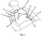
- the chest assembly 12 is preferably a one-piece flexible circuit that connects a plurality of electrode connectors 18 whereby the electrode connectors 18 are configured to connect to electrodes 20 or electrically conductive adhesives.
- the electrode connectors 18 have snap terminals that connect to electrodes 20 having snap terminals.
- each electrode connector 18 connects to an electrically conductive element or trace 39 for transmitting electrical signals.
- the electrically conductive elements or traces 39 run along the chest assembly 12 and connect to a chest assembly connector 21.
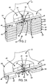
- FIG. 2 depicts a cross section of the chest assembly 12 at one of the electrode connector portions 18.
- the chest assembly 12 may have one or more outer layers 22, 24 that are comprised of any lightweight, flexible, moisture resistant, radiolucent or radiotransparent, and non-conductive material that is of sufficient thickness so as to not to be damaged when bent.
- the outer layers may be made of DuPont SONTARA®, polyethylene terephthalate (PET) or a liquid crystal polymer (LCP).
- the outer layers 22, 24 may be laser or die cut in order to avoid sharp edges along the chest assembly 12.
- the chest assembly 12 may be constructed with only one outer layer or no outer layers.
- the chest assembly is constructed with just one outer layer, that outer layer can be on either side of the chest assembly 12.
- One or more adhesive layers 26 may be used to secure the outer layers 22, 24 to one or more insulating or dielectric layers 30, 32.
- Insulating or dielectric layers 30, 32 may be constructed of MYLAR® (polyester) film or other suitable insulating material, such as Paralyne C.
- Layers 30, 32 have a first side 40 and a second side 42.
- the electrically conductive elements or traces 39 that connect to the electrode connectors 18 may be located on the first side 40 of layer 30.
- the electrically conductive elements or traces of the chest assembly may be of silver epoxy ink or any other suitable conductive material (e.g.
- the conductive elements or traces 39 run substantially side-by-side one another, in a fixed relationship and separated by sufficient distance such that electrical arcing or "cross-talk" among the conductive elements or traces is substantially avoided.
- the width and/or thickness of the conductive elements or traces 39 and the respective distance between them may be varied depending upon the conductive properties of the conductive material chosen for the conductive elements or traces.
- the ability of the electrode assembly to maintain electrical and physical integrity during and after defibrillation is an extremely important consideration that must be undertaken when determining the dimensions of the conductive elements or traces and the dielectric layers.
- the electrode assembly In order to meet the requirements of the current ANSI standard for defibrillation withstand, the electrode assembly must be able to survive a minimum of a 5000V discharge into the patient, during application of either a monoplasic or biplasic defibrillation waveform, whereby the energy delivered to the assembly is 360 joules.
- the chest assembly 12 is constructed of the thinnest and least number of layers electrically possible in order to reduce the weight and the density of the assembly to improve its comfort and radiolucency.
- the chest assembly 12 may be constructed to have a minimum configuration of only three layers. The three layers could consist of just a single dielectric or insulating layer 30, the layer of electrically conductive elements or traces 39, and a single outer layer 22.
- a shielding layer for further reducing any external interferences or radio frequency noise with the chest assembly 12 may be located on the second side 42 of the dielectric or insulating layer 32.
- the shielding layer may be constructed of single or multiple layers of dielectric, or electrically or magnetically conductive material.
- the chest assembly 12 may be constructed without a shielding layer without departing from the spirit and scope of the invention. If applied, the shielding layer is preferably comprised of an X-patterned grid.
- the back of the electrode connector 18 may also be covered with Mylar® to further insulate the chest assembly 12 and prevent an externally applied electric potential from entering the ECG system.
- the chest assembly 12 may also be constructed with an adhesive sheet (not shown) that partially or completely covers the chest assembly 12.
- the electrode connectors 18 may be sandwiched between the adhesive sheet and the outer layer 24 of the chest assembly 12.
- the adhesive sheet is constructed of polymers that have isotropic electrical conductive properties and/or anisotropic electrical conductive properties such that the regional specific impedance through the adhesive sheet is less than in a laterally oriented direction.
- the polymers are preferably hydropolymers, which are electrically conductive, relatively non-irritating to a patient's skin, and demonstrate excellent adhesive qualities. Suitable hydropolymer sheets for use with the present invention are available from Promeon of Boston, Massachusetts, under the product designation RG-60 Series Hydrogels.
- the adhesive having isotropic electrical conductive properties could be applied to the electrode connector 18 just prior to the attachment of the electrode 20 to the chest assembly 12.
- the adhesive could be applied between the electrode connector 18 and the electrode 20 or to the side of the electrode 20 that contacts or connects to tne patient.
- the chest assembly 12 would not be manufactured with an adhesive sheet. Instead, the health care provider would apply the adhesive to the electrode connector 18 and/or electrode 20 just prior to attaching the chest assembly 12 to the patient.
- the chest assembly 12 may be constructed to connect to any conventional electrode or sensor. More specifically, as shown in FIGS. 2 and 2A , at each point (i.e. connection point 10 ) where an electrode or sensor connects to the chest assembly 12, portions of the layers of the chest assembly 12 that reside on the patient side are removed or are not applied during manufacture and the first side 40 of the dielectric or insulating layer 30 containing the electrically conductive element or trace 39 is exposed. At each electrode or sensor connection point 10, the chest assembly 12 optionally includes an electrically conductive layer (not shown) that is adhered to the electrically conductive element or trace 39.
- the optional electrical adhesive layer may be a layer of silver epoxy or other suitable electrically conductive, adhesive material capable of adhering or securing the electrode or sensor to the chest assembly 12 and providing an electrical link between the electrode or sensor with the electrically conductive element or trace 39.
- the chest assembly 12 includes an aperture 50 formed therethrough.
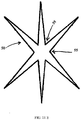
- the aperture 50 may be defined by a star cut pattern in the form of an asterisk with six legs 45 cut through each layer of the lead assembly 12. Flaps 55 are defined by the pairs of adjacent legs 45.
- the aperture 50 may be cut in various shapes and configurations without departing from the scope and spirit of the invention.
- the aperture 50 formed may be defined by three flaps 55.
- the aperture 50 may be defined by a semi-circular cut through the chest assembly 12, which forms one flap 55.
- FIG. 11A the aperture 50 may be defined by a star cut pattern in the form of an asterisk with six legs 45 cut through each layer of the lead assembly 12. Flaps 55 are defined by the pairs of adjacent legs 45.
- the aperture 50 may be cut in various shapes and configurations without departing from the scope and spirit of the invention.
- the aperture 50 formed may be defined by three flaps 55.
- the aperture 50 may be defined by a semi-circular cut through the chest assembly 12, which forms one flap 55.
- the aperture 50 may be defined by three flaps 55 and an open passage 35 formed where the three flaps 55 contact each other. Moreover, as shown in FIG. 11E , the aperture 50 may be defined by a star cut pattern with spacing between adjacent flaps 55.
- the flaps 55 are also electrically conductive and are contiguous to the electrically conductive element 39 of the chest assembly and provide an electrical connection between the electrically conductive element or trace 39 and the electrode or sensor upon insertion of the electrode or sensor in the aperture.
- the chest assembly 12 includes an electrode housing 60 on the non-skin contacting side of the chest assembly 12.
- the electrode housing 60 may be constructed from an elastomeric rubber, or any other suitable elastomeric or plastic material.
- the electrode housing 60 may be thermally bonded to the chest assembly 12 or adhered to the chest assembly 12 with any suitable adhesive.
- the electrode housing 60 contains an appropriately sized female void 65 for receiving the male portion of any conventional electrode or sensor 20.
- the electrode housing 60 should be constructed from a suitable elastomeric material so that the female void 65 will conform to different male portions of different shapes and sizes when such male portions are inserted up through the aperture 50 and into the female void 65.
- each electrode housing 60 is preferably appropriately color coded and/or contains alphanumeric designations to correspond to the particular electrode or sensor 20 attached to that electrode housing 60.
- the electrode housing 60 may be labeled RL, LA, LL, RA or V when the chest assembly is intended for ECG use.
- the electrode housing 60 is not bonded to the chest assembly 20, but is provided separately. In such an embodiment, the technician or health care provider setting up the equipment would press on the separate electrode housings 60 when attaching the chest assembly 12 to the electrode or sensor 20.
- the male portion of an electrode or sensor 20 is inserted into or positioned through the aperture 50.
- the male portion of the electrode or sensor 20 deflects the flaps 55.
- the resilience of the flaps 55 causes the flaps 55 to wipe against the male portion and mechanically hold the electrode or sensor 20 in the aperture 50 that is defined between the flaps 55.
- the pattern of the aperture 50 allows for the deflection of the flaps 55 with minimal force applied during the insertion of the male portion of the electrode or sensor 20.
- the male portion of the electrode or sensor 20 causes deflection of the flaps 55 without placing undue stresses on the ends of the flaps 55 which could otherwise result in the flaps being torn or losing their resilient property.
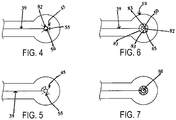
- the aperture 50 is formed through the electrically conductive element or trace 39 (as shown in FIGS. 2-2A and 4-7 ), electrical conductivity is obtained when the electrode or sensor 20 contacts the flaps 55. Further, when the electrode or sensor 20 firmly abuts or contacts the electrically conductive elements or traces 39 via the flaps 55, the electrical signals corresponding to physiological data of the patient pass from the electrode or sensor 20 to the electrically conductive element or trace 39, which, in turn, conveys the data to the body electronics unit 14 (as shown in FIG. 1 ).
- the electrode or sensor connector 18 is constructed to be radiolucent or radiotransparent whereby one or more of the conductive elements, traces or lead wires 39 of the chest assembly 12 seamlessly extends all the way to the aperture 50 of the connector 18 and forms various geometries that provide a continuous electrical path from the conductive elements or traces 39 to the electrode or sensor 20, but leaves much of the typical, substrate area of the flaps 55 free of solid conductive area by being largely comprised of non-conductive elements. As shown in FIG. 4 , preferably, the conductive element or trace 39 terminates into a single, small dot 82 of sufficient size to encircle the aperture 50.
- the electrical contact patch between the conductive area on the flap 55 and the electrode or sensor 20 must be of sufficient size to conduct the low level currents from the electrode or sensor 20 without undue voltage loss at the monitoring end. While this can be as limited as simply terminating the conductive trace 39 on a single flap 55, such a connection may not be electrically robust enough for use in a critical care setting. Alternative embodiments which would provide greater redundancy of the electrical connection between the flaps 55 and the electrode or sensor 20 may be required. For example, in one example shown in FIG. 6 , the conductive trace 39 terminates into two concentric, thin conductive circles 81 and 82 that surround the aperture 50. The innermost circle 82 is broken by the cuts 45 used to create the flaps 55.
- the concentric circles 81 and 82 are interconnected with a plurality of axial connections 83 between the inner and outer circles 81 and 82.
- One of skill in the art will readily recognize that the current carrying capacity of any individual axial connection 83 can be reduced when there are multiple axial connections. This allows for the use of thinner traces when constructing axial leads. Other examples are depicted in FIGS. 5 and 7 .
- outer or inner circles 81 and 82 can be continuous circles in the examples, they only partially encircle the aperture in the embodiment of the present invention, because it is advantageous to have conductive surfaces which do not fully encircle the electrode in order to reduce the area of potential non radiolucent conductors. This is readily achievable when the electrode itself has a 360° degree electrical contact patch. In such instance the use of semi-circles are possible so long as the total contact area with the electrode is robust enough to provide an acceptable signal and where necessary, can withstand a defibrillation shock without self-destructing.
- FIG. 7 depicts a connector with a mesh configuration which does not fall within the scope of the claims.
- the chest assembly 12 and the electrodes or sensors used with the chest assembly are constructed of radiolucent or radiotransparent materials. Radiolucent electrodes are known in the art and are sold by companies such as Kendle and 3M.
- the chest assembly 12 is preferably designed and configured to be used only a few times before being disposed. Accordingly, the chest assembly 12 is preferably constructed such that the electrodes or sensors 20 can be connected to and disconnected from the chest assembly 12 only a limited amount of times before the connection between the chest assembly 12 and the electrodes or sensors 20 become unusable and the chest assembly must be discarded.
- a disposable chest assembly 12 has many advantages. For example, disposable chest assemblies using the present invention offer hygienic advantages since such chest assemblies will be disposed of after each patient use - thus, reducing the spread of infection and disease. Further, assemblies of the present design may be made radiolucent by selection of appropriate materials thereby enabling their use in medical procedures where traditional snaps would interfere with imaging equipment. Further, the materials used to construct a disposable chest assembly, which uses the present invention are significantly less expensive than the materials used on other known disposable systems. Thus, the structure and construction of the present invention makes a disposable chest assembly very cost effective compared to other known disposable systems.
- the chest assembly 12 is capable of attaching to five or six electrodes 20 and provides a means for generally positioning the electrodes on the patient, thereby providing up to a "7 lead" analysis of the electrical activity of the heart.
- the electrode connectors 18 are preferably labeled and color-coded to ensure that the chest assembly 12 is properly positioned on the patient and connected to the appropriate electrodes.
- the electrode connectors are preferably labeled RL, LA, LL, RA and V, respectively.
- the chest assembly 12 is constructed such that the RA electrode connector is connected to an electrode positioned on the right side of the patient's chest about level of the first and second intercostal space, the LA electrode connector is connected to an electrode positioned on the left side of the patient's chest about level of the first and second intercostal space, the RL and LL electrode connectors are connected to electrodes positioned on the left side of the patient's torso, and the V electrode connector is connected to an electrode positioned in the middle of the patient's chest about level of the fourth and fifth intercostal space.
- the chest assembly 12 is preferably designed such that it is centered on the chest below the patient's clavicle.
- FIGS. 1 and 3 the chest assembly 12 is configured to provide flexible positioning of the chest assembly 12 on the patient.
- FIGS. 1 and 3 are for illustrative purposes only, and thus, the chest assembly 12, as depicted in FIGS. 1 and 3 , is not limited to any particular shape or configuration.
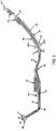
- FIG. 3 depicts the chest assembly 12 as having six electrode connectors 18.
- the chest assembly 12 has a linear section or tail 46 extending from the chest assembly connector 21.
- the tail 46 flows into an electrode retaining section 47.
- the electrode retaining section 47 has an arcuate section 48.
- the RA electrode connector 18a attaches to the first expandable arm 59.
- the arcuate section 48 flows into a transition section 52.
- the transition section 52 flows into a linear run 54.
- the LA electrode connector 18c attaches to the linear run 54.
- a second expandable arm 56, a first extension arm 58 and a second extension arm 68 attach to the linear run 54.
- the VA electrode connector 18d attaches to the first extension arm 58 and the VB electrode connector 18b attaches to the second extension arm 68.
- the RL electrode connector 18e and the LL electrode connector 18f attach to the second expandable arm 56.
- the electrode connector for the conventional ground or reference ECG electrode that is typically associated with the right leg i.e. the RL electrode connector labeled as 18e
- the present embodiment fixes this electrode in a location which is unlikely to show up in the imaging (as shown in a fixed position at expandable arm 56 in FIG. 3 ).
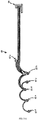
- the expandable arms 56, 59 are die cut in a serpentine pattern.
- the expandable arms 56, 59 comprise polypropylene or polyethylene fabric, Kapton, MYLAR®, or other flexible, memoryless material.
- the expandable arms 56, 59 expand, if necessary, by elongating the serpentine pattern. When expanded, a portion or the entire expandable arm is extended. Where only a portion of the expandable arm is extended, another portion remains folded.
- the expandable arms 56, 59 allow for extension as needed so that the chest assembly 12 can fit patients of various sizes and also allow for patient movement when the patient is wearing the chest assembly 12.
- the one or more extension arms 58, 68 allow for flexible positioning of the V electrode connector in the middle of the patient's chest such as placement at the electrode position V1, V2 or V3.
- the health care practitioner may desire not to utilize the extension arms 58, 68 for taking electrocardiograph measurements.
- the extension arms 58, 68 may be removably and/or selectively secured to the linear run 54 in order to ensure that the extension arms 58, 68 will not interfere with the placement and positioning of the chest assembly and to allow unimpeded access to the chest area.
- the extension arms 58, 68 may be die cut with a perforated seam that connects the extension arms 58, 68 to the linear run 54 along the length of the extension arms 58, 68. If the health care practitioner desires to use the extension arms 58, 68, the perforated seam is left unbroken so that the extension arms 58, 68 can be selectively positioned on the patient's chest.
- the chest assembly 12 can be used with a precordial assembly 60 to provide a "12-lead" analysis of the electrical activity of the heart.
- the precordial assembly 60 is a one-piece flexible circuit that connects a plurality of electrode connectors 62a-f.
- the electrode connectors 62 have snap terminals that connect to electrodes having snap terminals.
- Each electrode connector 62 connects to an electrically conductive element or trace for transmitting electrical signals from a patient's heart.
- the electrically conductive elements or traces run along the precordial assembly 60 and connect to a precordial assembly connector 66.
- the precordial assembly 60 may be constructed similarly to the chest assembly 12 discussed above.
- the precordial assembly 60 is capable of attaching to six electrodes selectively positioned on the abdomen and the middle of the chest of the patient.
- the electrode connectors 62 of the precordial assembly 60 are preferably labeled and color-coded so as to prevent a health care provider from applying or positioning the precordial assembly onto the patient improperly.
- the electrode connectors 62 are preferably labeled V1, V2, V3, V4, V5 and V6, respectively.
- the chest assembly 12 and the precordial assembly 60 detect electrical signals generated by the heart during each beat and transfer these signals to the body electronics unit 14.
- the body electronics unit 14 acquires signals from the RL, RA, LL, LA and V electrodes.
- the body electronics unit 14 uses the RL electrode as a ground reference.
- the body electronics unit 14 acquires signals from the RL, RA, LL and LA electrodes via the chest assembly 12 and acquires signals from the V1, V2, V3, V4, V5 and V6 electrodes via the precordial assembly 60.
- a various number of electrodes may be monitored by the system.
- the health care provider or physician may choose to use only two electrodes to monitor the heart, seven electrodes to monitor the heart, and so on.
- the present system is not limited to performing a "7-lead” and "12-lead” analysis of the heart.
- the chest assembly 12 and the precordial assembly 60 may be constructed to detect or transmit other vital signs of the patient which are detected by electrodes or sensors (e.g. pulse rate, respiration rate, heart rate and EEG).
- the chest assembly 12 of the present invention further improves the radiolucency of these types of monitoring devices by routing part of the assembly 12 outside of the area being imaged by electromagnetic diagnostic imaging devices such as X-ray, fluoroscopes, CAT scans and other magnetic resonance imaging devices.
- electromagnetic diagnostic imaging devices such as X-ray, fluoroscopes, CAT scans and other magnetic resonance imaging devices.
- the chest assembly 12 is placed on the chest such that the assembly lies across the chest and spans the entire chest width and/or length as described above.
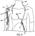
- the present invention discloses a method, as shown in FIG. 8 , in which the chest assembly 12 is of flexible size and configuration such that the electrode connectors 18 do not need to span horizontally across the chest. Rather, they may be applied around the periphery of the chest area while still maintaining proper placement along conventional ECG positions. As shown in FIG.
- the present invention also discloses a method for removing from the chest area that portion of the chest assembly 12 which crosses horizontally across the chest by placing or slinging the chest assembly 12 around the back of the neck 100 with the electrode connectors 18 still maintaining proper placement along conventional ECG positions around the periphery of the chest.
- the chest assembly 12 is configured to be of sufficient length for use around the neck 100 and the electrode connectors 18 are configured so as to line the periphery of the chest without crossing the chest area.
- the chest assembly 12 connects to the body electronics unit 14 via a chest assembly connector 21. Specifically, the chest assembly connector 21 inserts into a chest assembly port located in the body electronics unit 14.
- the precordial assembly 60 (not shown in FIG. 1 ) connects to the body electronics unit 14 via the precordial assembly connector 66. Specifically, the precordial assembly connector 66 inserts into a precordial assembly port. Resistors are connected to the chest assembly port and the precordial assembly port to prevent excessive electrical current from entering the body electronics unit 14 thereby ensuring that the body electronics unit 14 continues to operate properly in the presence of a strong electrical current caused by a defibrillator (i.e. a 5 kV defibrillator excitation).
- a defibrillator i.e. a 5 kV defibrillator excitation
- the chest assembly connector 21 and the precordial assembly connector 66 are specifically keyed or configured to prevent the assembly connectors 21, 66 from being inserted into the assembly ports backwards, misaligned or otherwise improperly. Moreover, the chest assembly connector 21 is keyed or configured such that it is not compatible with the precordial assembly port. Likewise, the precordial assembly connector 66 is keyed or configured such that it is not compatible with the chest assembly port. For example, the chest assembly connector 21 and/or the precordial assembly connector 66 could have tongues specifically configured or arranged to fit into corresponding grooves of the chest assembly port and the precordial assembly port, respectively. Accordingly, the chest assembly connector 21 can only be connected to the chest assembly port in one orientation.
- the chest assembly connector 21 and the precordial assembly connector 66 may have retaining clips or flanges 92 located on the sides of the connectors 21, 66 for removably securing the connectors 21, 66 into the assembly ports by providing a bias or tension against the assembly ports.
- other means may be used to removably secure the connectors 21, 66 in the assembly ports, such as screws, pins or the like.
- the electrically conductive elements or traces 39 are specifically configured on the connectors 21, 66 so as to ensure that the electrical signals from the heart are properly transmitted to the body electronics unit 14.
- the electrically conductive elements or traces are sufficiently spaced apart or otherwise isolated in fixed positions in order to achieve the necessary creepage and clearance distances to prevent electrical arcing between the elements.
- the spacing between the electrically conductive elements or traces permits the chest assembly and the precordial assembly to withstand defibrillation shock.
- the connectors 21, 66 may have ribs 96 for further electrical isolation between the conductive elements or traces and for preventing the electrically conductive elements or traces from coming into contact with metal objects or the like when the connectors 21, 66 are not inserted into the assembly ports.
- the chest assembly connector 21 may have a sensor pin or ground pin 98 that completes a circuit within the body electronics unit 14 when the chest assembly connector 21 is plugged into the chest assembly port, thereby activating the power and bringing the body electronics unit 14 out of "sleep mode.”
- the sensor pin 98 serves as a means for the body electronics unit 14 to identify the chest assembly 12 and to prevent the use of unauthorized chest assemblies or electrocardiograph wearables that are not designed to be used with the body electronics unit 14. In other words, the power of the body electronics unit 14 will not activate unless the body electronics unit 14 identifies or recognizes the sensor pin 98 of the chest assembly 12.
- the sensor pin may have a specific tongue that corresponds and fits into a groove located in the chest assembly port.
- the electrical signals are transmitted through the chest assembly and/or the precordial assembly to any conventional ECG monitor (including any legacy ECG monitor).
- the chest assembly and/or precordial assembly are connected to a body electronics unit 14, which is removably secured to the patient.
- the body electronics unit 14 may be attached to the patient's arm using a releasable arm band.
- the body electronics 14 unit transmits the electrical signals to a base station (not shown) via radio transmission and may utilize two-way wireless communication protocols which are generally known in the art (e.g. BLUETOOTH® or WiFi®).
- the base station is a portable transceiver that can be placed in any location and does not necessarily have to be placed or secured in any fixed location.
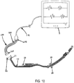
- the base station is preferably removably secured to a stationary or portable ECG monitor via suitable mounting means. Alternatively, the base station can be incorporated into the monitor. There may be instances where a base station will not be in every ward or hospital room for use with the body electronics unit 14. In such instances, as shown in FIGS. 8-10 , an adapter assembly 150 may be used to directly connect the chest assembly 12 or the precordial assembly 60 to the ECG monitor 5. In one exemplary embodiment, the adapter assembly 150 allows the chest assembly 12 or precordial assembly to be plugged directly into a conventional or existing telemetry transmitter.
- the adapter assembly 150 has an assembly receptacle 165 that connects to the chest assembly 12 or the precordial assembly 60 (not shown in FIG.
- the adapter assembly 150 allows the chest assembly 12 or the precordial assembly 60 to be plugged directly into a conventional or existing ECG monitor trunk cable 170. Instead of having a telemetry box receptacle, the adapter assembly 150 has a cable assembly 185 for connecting to a conventional or existing ECG monitor trunk cable. In another exemplary embodiment, the adapter assembly 150 allows the chest assembly 12 or precordial assembly 60 to be plugged directly into standard lead wires that connect to an ECG monitor.
- the electrode assembly 12 was constructed of the following substantially radiolucent or radiotransparent layers: a skin-contacting outer layer 24 made of DuPont SONTARA® of 0.5 mm thickness, tri-laminate polyester adhesive layers 26 made of 4 Pillars Co.
- DSMI adhesive of 0.1 mm thickness
- dielectric layers 30 and 32 made of Acheson Electrodag 452SS dielectric ink of 0.01 mm thickness
- a conductive ink layer 39 made of Toyobo DW-351 silver ink whereby each conductive trace or element was 0.008 mm in thickness and 17 microns in width wherein each conductive trace or element was separated by a distance of 0.050 mm
- an outer layer 22 made of Toray T60 polyester of 0.125 mm thickness
- an electrode housing 60 made of polyester and Poron of 5 mm thickness.
- the shape and configuration of the electrode assembly 12 was as depicted in FIG. 3 .
- the conductive ink layer 39 at the electrode connector 18 terminated at the electrode connector 18 in the geometrical pattern shown in FIG.
- FIG. 12A depicts an x-ray of an adult male chest whereby standard lead wires with snap electrode connections were applied to the chest.
- the lead wires and the electrode connector portions are strongly visible on the x-ray and greatly interfere with the ability to view the x-rayed subject.
- the radiolucent and radiotransparent characteristics of the present invention are vastly improved over the standard lead wire equipment.
- the assembly of the present invention can be used to connect to a number of other sensors or electrodes for other monitoring applications without departing from the intended spirit or scope of the present invention.
- sensors used to acquire pulse data, respiration rate data, EEG signal data or pulse oximeter data may all be used with the present invention.
Landscapes
- Health & Medical Sciences (AREA)
- Life Sciences & Earth Sciences (AREA)
- Medical Informatics (AREA)
- Biophysics (AREA)
- Pathology (AREA)
- Engineering & Computer Science (AREA)
- Biomedical Technology (AREA)
- Heart & Thoracic Surgery (AREA)
- Physics & Mathematics (AREA)
- Molecular Biology (AREA)
- Surgery (AREA)
- Animal Behavior & Ethology (AREA)
- General Health & Medical Sciences (AREA)
- Public Health (AREA)
- Veterinary Medicine (AREA)
- Cardiology (AREA)
- Chemical & Material Sciences (AREA)
- Dispersion Chemistry (AREA)
- Measurement And Recording Of Electrical Phenomena And Electrical Characteristics Of The Living Body (AREA)
Claims (10)
- Ensemble sensiblement radiotransparent (12 ; 60) pour connecter un capteur ou une électrode physiologique porté(e) par un patient à un moniteur, comprenant :un substrat non conducteur flexible ayant une extrémité proximale et une extrémité distale ;au moins une ouverture (50) formée dans le substrat et calibrée pour recevoir un capteur ou une électrode ;au moins un tracé conducteur (39) disposé sur au moins une surface du substrat non conducteur, dans lequel le au moins un tracé conducteur est capable de conduire un courant entre le capteur ou l'électrode et l'extrémité distale du substrat ;un moyen (21 ; 66) pour fournir une connexion électrique entre l'extrémité distale du substrat et un moniteur ; etau moins un connecteur électrique radiotransparent (18, 62a-f) comprenant la au moins une ouverture et au moins une extension linéaire du au moins un tracé conducteur qui s'étend jusqu'à l'ouverture, dans lequel le connecteur électrique est destiné à établir un contact électrique avec le capteur ou l'électrode ;ledit ensemble étant caractérisé en ce que la au moins une extension linéaire du au moins un tracé conducteur se termine en deux cercles partiels concentriques (81, 82) entourant l'ouverture et dans lequel le cercle partiel externe est connecté au cercle partiel interne par au moins un tracé coaxial (83).
- Ensemble radiotransparent selon la revendication 1, dans lequel l'ouverture forme au moins un volet (55) pour s'engager sur un capteur ou une électrode positionné(e) à travers l'ouverture.
- Ensemble radiotransparent selon la revendication 1, comprenant en outre un adhésif conducteur (26) situé sur au moins un côté de l'ensemble d'électrode.
- Ensemble radiotransparent selon la revendication 1, comprenant en outre une pluralité de logements d'électrodes (60), chaque logement d'électrode étant positionné sur une ouverture formée dans l'ensemble et contenant une partie élastomère définissant un vide femelle (65) pour recevoir une partie conductrice de l'électrode.
- Ensemble radiotransparent selon la revendication 1, dans lequel le au moins un connecteur électrique est mobile pour permettre un repositionnement du capteur ou de l'électrode autour de la périphérie externe du torse du patient de sorte que l'accès à la poitrine ne soit sensiblement pas empêché.
- Ensemble radiotransparent selon la revendication 5, dans lequel une partie de l'ensemble d'électrode est destinée à être positionnée autour de la nuque du patient.
- Ensemble radiotransparent selon la revendication 1, dans lequel le connecteur électrique qui est à même de se connecter à l'électrode ECG de terre ou de référence classique est en position fixe sur le périmètre du torse afin d'empêcher la mise en place involontaire de l'électrode dans une zone qui empêche un accès à la poitrine du patient.
- Ensemble radiotransparent selon la revendication 1, dans lequel le au moins un connecteur électrique a une capacité de transport de courant suffisante pour résister à au moins un choc de défibrillation de 360 Joules sans être endommagé.
- Ensemble radiotransparent selon la revendication 1, dans lequel le substrat est constitué de poly(téréphtalate d'éthylène) ou d'un polymère en cristaux liquides.
- Ensemble radiotransparent selon la revendication 1, dans lequel le au moins un tracé conducteur est constitué de cuivre, d'or, de carbone, de nanotube de carbone, d'oxyde d'indium et d'étain, d'argent ou de graphite.
Applications Claiming Priority (2)
| Application Number | Priority Date | Filing Date | Title |
|---|---|---|---|
| US89739007P | 2007-01-25 | 2007-01-25 | |
| PCT/US2008/052085 WO2008092098A2 (fr) | 2007-01-25 | 2008-01-25 | Ensemble d'électrode ou de capteur radiotransparent |
Publications (3)
| Publication Number | Publication Date |
|---|---|
| EP2109397A2 EP2109397A2 (fr) | 2009-10-21 |
| EP2109397A4 EP2109397A4 (fr) | 2013-04-17 |
| EP2109397B1 true EP2109397B1 (fr) | 2020-02-19 |
Family
ID=39645198
Family Applications (1)
| Application Number | Title | Priority Date | Filing Date |
|---|---|---|---|
| EP08728309.9A Active EP2109397B1 (fr) | 2007-01-25 | 2008-01-25 | Ensemble radiotransparent connectable à une électrode ou un capteur |
Country Status (3)
| Country | Link |
|---|---|
| US (2) | US9211075B2 (fr) |
| EP (1) | EP2109397B1 (fr) |
| WO (1) | WO2008092098A2 (fr) |
Families Citing this family (72)
| Publication number | Priority date | Publication date | Assignee | Title |
|---|---|---|---|---|
| US8668651B2 (en) | 2006-12-05 | 2014-03-11 | Covidien Lp | ECG lead set and ECG adapter system |
| EP2196142A4 (fr) * | 2007-09-25 | 2012-02-29 | Nihon Kohden Corp | Feuille d'électrode et son procédé de fabrication |
| US8038484B2 (en) | 2007-12-11 | 2011-10-18 | Tyco Healthcare Group Lp | ECG electrode connector |
| USD737979S1 (en) | 2008-12-09 | 2015-09-01 | Covidien Lp | ECG electrode connector |
| US8694080B2 (en) | 2009-10-21 | 2014-04-08 | Covidien Lp | ECG lead system |
| WO2012088398A2 (fr) * | 2010-12-22 | 2012-06-28 | Cardioinsight Technologies, Inc. | Appareil de détection multicouche |
| WO2013016112A1 (fr) * | 2011-07-22 | 2013-01-31 | Covidien Lp | Système d'électrode ecg |
| CA2841601C (fr) | 2011-07-22 | 2017-11-28 | David Zhou | Connecteur pour electrode d'ecg |
| WO2013152094A1 (fr) * | 2012-04-03 | 2013-10-10 | Altec, Inc. | Capteur biomédical conforme à profil bas jetable |
| US10413251B2 (en) | 2012-10-07 | 2019-09-17 | Rhythm Diagnostic Systems, Inc. | Wearable cardiac monitor |
| US10244949B2 (en) | 2012-10-07 | 2019-04-02 | Rhythm Diagnostic Systems, Inc. | Health monitoring systems and methods |
| US10610159B2 (en) | 2012-10-07 | 2020-04-07 | Rhythm Diagnostic Systems, Inc. | Health monitoring systems and methods |
| WO2014062738A1 (fr) * | 2012-10-15 | 2014-04-24 | Jordan Neuroscience, Inc. | Unité pour eeg sans fil |
| EP2967396B1 (fr) | 2013-03-15 | 2019-02-13 | Kpr U.S., Llc | Connecteur d'électrode à élément conducteur |
| US9408546B2 (en) | 2013-03-15 | 2016-08-09 | Covidien Lp | Radiolucent ECG electrode system |
| USD771818S1 (en) | 2013-03-15 | 2016-11-15 | Covidien Lp | ECG electrode connector |
| US10314506B2 (en) * | 2013-05-15 | 2019-06-11 | Polar Electro Oy | Heart activity sensor structure |
| DE102013108810A1 (de) * | 2013-08-14 | 2015-02-19 | Capical Gmbh | Textile kapazitive Elektrode, Verfahren zu deren Herstellung sowie Verwendung |
| US10736531B2 (en) | 2013-09-25 | 2020-08-11 | Bardy Diagnostics, Inc. | Subcutaneous insertable cardiac monitor optimized for long term, low amplitude electrocardiographic data collection |
| US9655537B2 (en) | 2013-09-25 | 2017-05-23 | Bardy Diagnostics, Inc. | Wearable electrocardiography and physiology monitoring ensemble |
| US9615763B2 (en) | 2013-09-25 | 2017-04-11 | Bardy Diagnostics, Inc. | Ambulatory electrocardiography monitor recorder optimized for capturing low amplitude cardiac action potential propagation |
| US10667711B1 (en) | 2013-09-25 | 2020-06-02 | Bardy Diagnostics, Inc. | Contact-activated extended wear electrocardiography and physiological sensor monitor recorder |
| US10806360B2 (en) | 2013-09-25 | 2020-10-20 | Bardy Diagnostics, Inc. | Extended wear ambulatory electrocardiography and physiological sensor monitor |
| US20190167139A1 (en) | 2017-12-05 | 2019-06-06 | Gust H. Bardy | Subcutaneous P-Wave Centric Insertable Cardiac Monitor For Long Term Electrocardiographic Monitoring |
| US9737224B2 (en) | 2013-09-25 | 2017-08-22 | Bardy Diagnostics, Inc. | Event alerting through actigraphy embedded within electrocardiographic data |
| US10888239B2 (en) | 2013-09-25 | 2021-01-12 | Bardy Diagnostics, Inc. | Remote interfacing electrocardiography patch |
| US10820801B2 (en) | 2013-09-25 | 2020-11-03 | Bardy Diagnostics, Inc. | Electrocardiography monitor configured for self-optimizing ECG data compression |
| US9364155B2 (en) | 2013-09-25 | 2016-06-14 | Bardy Diagnostics, Inc. | Self-contained personal air flow sensing monitor |
| US10624551B2 (en) | 2013-09-25 | 2020-04-21 | Bardy Diagnostics, Inc. | Insertable cardiac monitor for use in performing long term electrocardiographic monitoring |
| US10736529B2 (en) | 2013-09-25 | 2020-08-11 | Bardy Diagnostics, Inc. | Subcutaneous insertable electrocardiography monitor |
| US9700227B2 (en) | 2013-09-25 | 2017-07-11 | Bardy Diagnostics, Inc. | Ambulatory electrocardiography monitoring patch optimized for capturing low amplitude cardiac action potential propagation |
| US10251576B2 (en) | 2013-09-25 | 2019-04-09 | Bardy Diagnostics, Inc. | System and method for ECG data classification for use in facilitating diagnosis of cardiac rhythm disorders with the aid of a digital computer |
| US11723575B2 (en) | 2013-09-25 | 2023-08-15 | Bardy Diagnostics, Inc. | Electrocardiography patch |
| US9408545B2 (en) | 2013-09-25 | 2016-08-09 | Bardy Diagnostics, Inc. | Method for efficiently encoding and compressing ECG data optimized for use in an ambulatory ECG monitor |
| US9504423B1 (en) | 2015-10-05 | 2016-11-29 | Bardy Diagnostics, Inc. | Method for addressing medical conditions through a wearable health monitor with the aid of a digital computer |
| US10433751B2 (en) | 2013-09-25 | 2019-10-08 | Bardy Diagnostics, Inc. | System and method for facilitating a cardiac rhythm disorder diagnosis based on subcutaneous cardiac monitoring data |
| US9545204B2 (en) | 2013-09-25 | 2017-01-17 | Bardy Diagnostics, Inc. | Extended wear electrocardiography patch |
| US10433748B2 (en) | 2013-09-25 | 2019-10-08 | Bardy Diagnostics, Inc. | Extended wear electrocardiography and physiological sensor monitor |
| US9717432B2 (en) | 2013-09-25 | 2017-08-01 | Bardy Diagnostics, Inc. | Extended wear electrocardiography patch using interlaced wire electrodes |
| WO2015048323A2 (fr) * | 2013-09-25 | 2015-04-02 | Bardy Diagnostics, Inc. | Timbre d'électrocardiographie à utilisation prolongée utilisant des fils-électrodes entrelacés |
| US10463269B2 (en) | 2013-09-25 | 2019-11-05 | Bardy Diagnostics, Inc. | System and method for machine-learning-based atrial fibrillation detection |
| US9408551B2 (en) | 2013-11-14 | 2016-08-09 | Bardy Diagnostics, Inc. | System and method for facilitating diagnosis of cardiac rhythm disorders with the aid of a digital computer |
| US9345414B1 (en) | 2013-09-25 | 2016-05-24 | Bardy Diagnostics, Inc. | Method for providing dynamic gain over electrocardiographic data with the aid of a digital computer |
| US9619660B1 (en) | 2013-09-25 | 2017-04-11 | Bardy Diagnostics, Inc. | Computer-implemented system for secure physiological data collection and processing |
| US10799137B2 (en) | 2013-09-25 | 2020-10-13 | Bardy Diagnostics, Inc. | System and method for facilitating a cardiac rhythm disorder diagnosis with the aid of a digital computer |
| US9775536B2 (en) | 2013-09-25 | 2017-10-03 | Bardy Diagnostics, Inc. | Method for constructing a stress-pliant physiological electrode assembly |
| US9655538B2 (en) | 2013-09-25 | 2017-05-23 | Bardy Diagnostics, Inc. | Self-authenticating electrocardiography monitoring circuit |
| US11213237B2 (en) | 2013-09-25 | 2022-01-04 | Bardy Diagnostics, Inc. | System and method for secure cloud-based physiological data processing and delivery |
| WO2015048194A1 (fr) | 2013-09-25 | 2015-04-02 | Bardy Diagnostics, Inc. | Moniteur personnel autonome de détection du débit d'air |
| GB2536163B (en) * | 2013-10-17 | 2017-11-15 | Monica Healthcare Ltd | Apparatus and method for detecting an abdominal electrophysiological signal |
| WO2016010990A2 (fr) * | 2014-07-15 | 2016-01-21 | Avery Dennison Corporation | Dispositifs de détection et procédés d'application d'un dispositif de détection |
| US11330984B2 (en) * | 2015-06-19 | 2022-05-17 | The Trustees Of The Stevens Institute Of Technology | Wearable graphene sensors |
| US10918296B1 (en) * | 2015-07-13 | 2021-02-16 | Vital Connect, Inc. | Flexible electrocardiogram (ECG) pads |
| US20170079543A1 (en) * | 2015-09-18 | 2017-03-23 | Neurorex Inc | Imaging compatible electrode-set for measurement of body electrical signals and methods for fabricating the same using ink-jet printing |
| EP3386561B1 (fr) | 2015-12-11 | 2023-05-03 | NxStage Medical, Inc. | Systèmes , procédés et dispositifs de raccord pour ligne de fluide |
| US11375937B2 (en) * | 2016-12-21 | 2022-07-05 | Prolira B.V. | Electrode carrier for electrophysiological measurement |
| US20180271444A1 (en) * | 2017-03-21 | 2018-09-27 | Rhythmlink International, Llc | Unitary template for neurological monitoring electrodes |
| CA3067690A1 (fr) | 2017-06-20 | 2018-12-27 | Innovation Ventures Ip At Ukhs, Llc | Vetement de test d'effort et procede d'utilisation |
| RU184638U1 (ru) * | 2018-05-16 | 2018-11-01 | Денис Леонидович Каркоцкий | Пластинчатый электрод для регистрации биосигналов активности головного мозга человека |
| US11684305B2 (en) | 2018-06-02 | 2023-06-27 | Seyedhesam Sadeghian-Motahar | Electrode array configuration on a flexible substrate for electro-oculogram recording |
| PL3626158T3 (pl) * | 2018-09-21 | 2023-10-09 | Smartmedics Sp. Z O.O. | Plaster elektrodowy z wieloma punktami pomiarowymi |
| MX2021008735A (es) * | 2019-01-24 | 2021-08-24 | Otsuka Pharma Co Ltd | Sensor portable elastico. |
| CN113631097A (zh) | 2019-01-25 | 2021-11-09 | Rds公司 | 健康监测系统及方法 |
| US11096579B2 (en) | 2019-07-03 | 2021-08-24 | Bardy Diagnostics, Inc. | System and method for remote ECG data streaming in real-time |
| US11116451B2 (en) | 2019-07-03 | 2021-09-14 | Bardy Diagnostics, Inc. | Subcutaneous P-wave centric insertable cardiac monitor with energy harvesting capabilities |
| WO2021041961A1 (fr) | 2019-08-28 | 2021-03-04 | Rhythm Diagnostic Systems, Inc. | Systèmes et procédés de surveillance de signes vitaux ou de santé |
| CN110680303B (zh) * | 2019-09-16 | 2025-08-29 | 深圳市理邦精密仪器股份有限公司 | 一种检测探头以及胎儿监护仪 |
| JP7446757B2 (ja) * | 2019-10-04 | 2024-03-11 | 日本光電工業株式会社 | 生体電極ユニット |
| US11744501B2 (en) | 2020-05-07 | 2023-09-05 | GE Precision Healthcare LLC | Multi-sensor patch |
| US20240374212A1 (en) * | 2021-04-07 | 2024-11-14 | Smartcardia Sa | System for monitoring a vital sign |
| NL2032605B1 (en) * | 2022-07-26 | 2024-02-05 | Bambi Belt Holding B V | Baby vital sign monitoring belt |
| US20250345141A1 (en) * | 2024-05-10 | 2025-11-13 | Michael Campagna | Medical imaging compatible radiolucent actuation |
Citations (5)
| Publication number | Priority date | Publication date | Assignee | Title |
|---|---|---|---|---|
| US4736752A (en) * | 1986-11-28 | 1988-04-12 | Axelgaard Manufacturing Co., Ltd. | Transcutaneous medical electrode |
| US5265579A (en) * | 1992-09-21 | 1993-11-30 | Ferrari R Keith | X-ray transparent monitoring electrode and method for making |
| US5366497A (en) * | 1992-03-31 | 1994-11-22 | Cardiotronics, Inc. | Non-invasive, radiolucent cardiac electrode |
| US5843155A (en) * | 1997-06-12 | 1998-12-01 | Axelgaard Manufacturing Company, Ltd. | Current-controlling electrode system |
| US20020177767A1 (en) * | 2000-05-16 | 2002-11-28 | Steve Burton | Sensor for biopotential measurements |
Family Cites Families (15)
| Publication number | Priority date | Publication date | Assignee | Title |
|---|---|---|---|---|
| US4353372A (en) * | 1980-02-11 | 1982-10-12 | Bunker Ramo Corporation | Medical cable set and electrode therefor |
| US4709704A (en) * | 1984-03-06 | 1987-12-01 | The Kendall Company | Monitoring device for bio-signals |
| US4938231A (en) * | 1985-10-22 | 1990-07-03 | Telectronics N.V. | Defibrillator electrode |
| US5061875A (en) * | 1990-06-20 | 1991-10-29 | Burle Technologies, Inc. | Focus electrode for elongated hexagonal photomultiplier tube |
| US5191886A (en) * | 1991-04-18 | 1993-03-09 | Physio-Control Corporation | Multiple electrode strip |
| US5586346A (en) * | 1994-02-15 | 1996-12-24 | Support Systems, International | Method and apparatus for supporting and for supplying therapy to a patient |
| US5724984A (en) * | 1995-01-26 | 1998-03-10 | Cambridge Heart, Inc. | Multi-segment ECG electrode and system |
| US5645063A (en) * | 1995-06-05 | 1997-07-08 | Quinton Instrument Company | Skin electrode having multiple conductive center members |
| US5824033A (en) * | 1995-12-08 | 1998-10-20 | Ludlow Corporation | Multifunction electrode |
| US6259939B1 (en) * | 1997-08-20 | 2001-07-10 | R. Z. Comparative Diagnostics Ltd. | Electrocardiography electrodes holder including electrocardiograph electronics |
| US6434410B1 (en) * | 1998-06-19 | 2002-08-13 | Aspect Medical Systems, Inc. | Electrode for measuring electrophysiological signals using liquid electrolytic gel with a high salt concentration |
| WO2002005700A2 (fr) * | 2000-07-18 | 2002-01-24 | Motorola, Inc. | Procede et systeme d'electrocardiographe sans fil |
| US7933642B2 (en) * | 2001-07-17 | 2011-04-26 | Rud Istvan | Wireless ECG system |
| US20070142738A1 (en) * | 2005-12-16 | 2007-06-21 | Chin-Yeh Hung | Dynamic heart rate monitor |
| DE102008051536A1 (de) * | 2008-10-14 | 2010-04-15 | Cairos Technologies Ag | Kleidungsstück zum Überwachen physiologischer Eigenschaften |
-
2008
- 2008-01-25 EP EP08728309.9A patent/EP2109397B1/fr active Active
- 2008-01-25 WO PCT/US2008/052085 patent/WO2008092098A2/fr not_active Ceased
-
2013
- 2013-05-06 US US13/888,107 patent/US9211075B2/en active Active
-
2015
- 2015-12-14 US US14/968,395 patent/US9795316B2/en active Active
Patent Citations (5)
| Publication number | Priority date | Publication date | Assignee | Title |
|---|---|---|---|---|
| US4736752A (en) * | 1986-11-28 | 1988-04-12 | Axelgaard Manufacturing Co., Ltd. | Transcutaneous medical electrode |
| US5366497A (en) * | 1992-03-31 | 1994-11-22 | Cardiotronics, Inc. | Non-invasive, radiolucent cardiac electrode |
| US5265579A (en) * | 1992-09-21 | 1993-11-30 | Ferrari R Keith | X-ray transparent monitoring electrode and method for making |
| US5843155A (en) * | 1997-06-12 | 1998-12-01 | Axelgaard Manufacturing Company, Ltd. | Current-controlling electrode system |
| US20020177767A1 (en) * | 2000-05-16 | 2002-11-28 | Steve Burton | Sensor for biopotential measurements |
Also Published As
| Publication number | Publication date |
|---|---|
| WO2008092098A2 (fr) | 2008-07-31 |
| EP2109397A4 (fr) | 2013-04-17 |
| EP2109397A2 (fr) | 2009-10-21 |
| US20160166170A1 (en) | 2016-06-16 |
| US20130345539A1 (en) | 2013-12-26 |
| US9795316B2 (en) | 2017-10-24 |
| US9211075B2 (en) | 2015-12-15 |
| WO2008092098A3 (fr) | 2008-10-09 |
Similar Documents
| Publication | Publication Date | Title |
|---|---|---|
| EP2109397B1 (fr) | Ensemble radiotransparent connectable à une électrode ou un capteur | |
| JP7459072B2 (ja) | 複数の測定点を備えた電極パッチ | |
| EP2091424B1 (fr) | Détecteur d'ecg portatif repositionnable | |
| US6453186B1 (en) | Electrocardiogram electrode patch | |
| ES2538680T3 (es) | Sistema de electrocardiógrafo sin hilos | |
| EP1720446B1 (fr) | Dispositif sans fil portable permettant de controler, analyser et communiquer des statuts physiologiques | |
| FI126093B (fi) | Järjestely ja menetelmä elektrodimittausten suorittamiseksi | |
| US7860557B2 (en) | Radiolucent chest assembly | |
| JP6125019B2 (ja) | 電極パッドセット | |
| US8238996B2 (en) | Electrode array | |
| US20100059274A1 (en) | Electrode system and lead assembly for physiological monitoring | |
| KR20090127434A (ko) | 생리학적 정보를 계측하기 위한 전극선 세트 | |
| KR101780926B1 (ko) | 패치형 심전도 센서 | |
| US9226678B1 (en) | Connector device for a cable apparatus | |
| US11817660B1 (en) | Connector device for a cable apparatus | |
| WO2022170057A1 (fr) | Électrodes sérigraphiées destinées à un article pour électrocardiogramme | |
| EP4397234A1 (fr) | Ensemble d'imagerie d'impédance électrique | |
| US20260041353A1 (en) | Noise Mitigating Structure For A Pad For Electrical Components | |
| US20250073452A1 (en) | Radiotransparent electrode | |
| US20240324931A1 (en) | Electrocardiographic imaging system and method |
Legal Events
| Date | Code | Title | Description |
|---|---|---|---|
| PUAI | Public reference made under article 153(3) epc to a published international application that has entered the european phase |
Free format text: ORIGINAL CODE: 0009012 |
|
| 17P | Request for examination filed |
Effective date: 20090727 |
|
| AK | Designated contracting states |
Kind code of ref document: A2 Designated state(s): AT BE BG CH CY CZ DE DK EE ES FI FR GB GR HR HU IE IS IT LI LT LU LV MC MT NL NO PL PT RO SE SI SK TR |
|
| DAX | Request for extension of the european patent (deleted) | ||
| A4 | Supplementary search report drawn up and despatched |
Effective date: 20130320 |
|
| RIC1 | Information provided on ipc code assigned before grant |
Ipc: A61B 5/0408 20060101AFI20130314BHEP |
|
| 17Q | First examination report despatched |
Effective date: 20150601 |
|
| STAA | Information on the status of an ep patent application or granted ep patent |
Free format text: STATUS: EXAMINATION IS IN PROGRESS |
|
| GRAP | Despatch of communication of intention to grant a patent |
Free format text: ORIGINAL CODE: EPIDOSNIGR1 |
|
| STAA | Information on the status of an ep patent application or granted ep patent |
Free format text: STATUS: GRANT OF PATENT IS INTENDED |
|
| INTG | Intention to grant announced |
Effective date: 20181031 |
|
| GRAJ | Information related to disapproval of communication of intention to grant by the applicant or resumption of examination proceedings by the epo deleted |
Free format text: ORIGINAL CODE: EPIDOSDIGR1 |
|
| STAA | Information on the status of an ep patent application or granted ep patent |
Free format text: STATUS: EXAMINATION IS IN PROGRESS |
|
| GRAP | Despatch of communication of intention to grant a patent |
Free format text: ORIGINAL CODE: EPIDOSNIGR1 |
|
| INTC | Intention to grant announced (deleted) | ||
| STAA | Information on the status of an ep patent application or granted ep patent |
Free format text: STATUS: GRANT OF PATENT IS INTENDED |
|
| INTG | Intention to grant announced |
Effective date: 20190808 |
|
| GRAS | Grant fee paid |
Free format text: ORIGINAL CODE: EPIDOSNIGR3 |
|
| GRAA | (expected) grant |
Free format text: ORIGINAL CODE: 0009210 |
|
| STAA | Information on the status of an ep patent application or granted ep patent |
Free format text: STATUS: THE PATENT HAS BEEN GRANTED |
|
| RAP1 | Party data changed (applicant data changed or rights of an application transferred) |
Owner name: LIFESYNC CORPORATION |
|
| AK | Designated contracting states |
Kind code of ref document: B1 Designated state(s): AT BE BG CH CY CZ DE DK EE ES FI FR GB GR HR HU IE IS IT LI LT LU LV MC MT NL NO PL PT RO SE SI SK TR |
|
| REG | Reference to a national code |
Ref country code: GB Ref legal event code: FG4D |
|
| REG | Reference to a national code |
Ref country code: CH Ref legal event code: EP |
|
| REG | Reference to a national code |
Ref country code: DE Ref legal event code: R096 Ref document number: 602008062156 Country of ref document: DE |
|
| REG | Reference to a national code |
Ref country code: AT Ref legal event code: REF Ref document number: 1234006 Country of ref document: AT Kind code of ref document: T Effective date: 20200315 |
|
| REG | Reference to a national code |
Ref country code: IE Ref legal event code: FG4D |
|
| REG | Reference to a national code |
Ref country code: NL Ref legal event code: MP Effective date: 20200219 |
|
| PG25 | Lapsed in a contracting state [announced via postgrant information from national office to epo] |
Ref country code: FI Free format text: LAPSE BECAUSE OF FAILURE TO SUBMIT A TRANSLATION OF THE DESCRIPTION OR TO PAY THE FEE WITHIN THE PRESCRIBED TIME-LIMIT Effective date: 20200219 Ref country code: NO Free format text: LAPSE BECAUSE OF FAILURE TO SUBMIT A TRANSLATION OF THE DESCRIPTION OR TO PAY THE FEE WITHIN THE PRESCRIBED TIME-LIMIT Effective date: 20200519 |
|
| REG | Reference to a national code |
Ref country code: LT Ref legal event code: MG4D |
|
| PG25 | Lapsed in a contracting state [announced via postgrant information from national office to epo] |
Ref country code: BG Free format text: LAPSE BECAUSE OF FAILURE TO SUBMIT A TRANSLATION OF THE DESCRIPTION OR TO PAY THE FEE WITHIN THE PRESCRIBED TIME-LIMIT Effective date: 20200519 Ref country code: GR Free format text: LAPSE BECAUSE OF FAILURE TO SUBMIT A TRANSLATION OF THE DESCRIPTION OR TO PAY THE FEE WITHIN THE PRESCRIBED TIME-LIMIT Effective date: 20200520 Ref country code: SE Free format text: LAPSE BECAUSE OF FAILURE TO SUBMIT A TRANSLATION OF THE DESCRIPTION OR TO PAY THE FEE WITHIN THE PRESCRIBED TIME-LIMIT Effective date: 20200219 Ref country code: LV Free format text: LAPSE BECAUSE OF FAILURE TO SUBMIT A TRANSLATION OF THE DESCRIPTION OR TO PAY THE FEE WITHIN THE PRESCRIBED TIME-LIMIT Effective date: 20200219 Ref country code: HR Free format text: LAPSE BECAUSE OF FAILURE TO SUBMIT A TRANSLATION OF THE DESCRIPTION OR TO PAY THE FEE WITHIN THE PRESCRIBED TIME-LIMIT Effective date: 20200219 Ref country code: IS Free format text: LAPSE BECAUSE OF FAILURE TO SUBMIT A TRANSLATION OF THE DESCRIPTION OR TO PAY THE FEE WITHIN THE PRESCRIBED TIME-LIMIT Effective date: 20200619 |
|
| PG25 | Lapsed in a contracting state [announced via postgrant information from national office to epo] |
Ref country code: NL Free format text: LAPSE BECAUSE OF FAILURE TO SUBMIT A TRANSLATION OF THE DESCRIPTION OR TO PAY THE FEE WITHIN THE PRESCRIBED TIME-LIMIT Effective date: 20200219 |
|
| PG25 | Lapsed in a contracting state [announced via postgrant information from national office to epo] |
Ref country code: SK Free format text: LAPSE BECAUSE OF FAILURE TO SUBMIT A TRANSLATION OF THE DESCRIPTION OR TO PAY THE FEE WITHIN THE PRESCRIBED TIME-LIMIT Effective date: 20200219 Ref country code: PT Free format text: LAPSE BECAUSE OF FAILURE TO SUBMIT A TRANSLATION OF THE DESCRIPTION OR TO PAY THE FEE WITHIN THE PRESCRIBED TIME-LIMIT Effective date: 20200712 Ref country code: RO Free format text: LAPSE BECAUSE OF FAILURE TO SUBMIT A TRANSLATION OF THE DESCRIPTION OR TO PAY THE FEE WITHIN THE PRESCRIBED TIME-LIMIT Effective date: 20200219 Ref country code: CZ Free format text: LAPSE BECAUSE OF FAILURE TO SUBMIT A TRANSLATION OF THE DESCRIPTION OR TO PAY THE FEE WITHIN THE PRESCRIBED TIME-LIMIT Effective date: 20200219 Ref country code: LT Free format text: LAPSE BECAUSE OF FAILURE TO SUBMIT A TRANSLATION OF THE DESCRIPTION OR TO PAY THE FEE WITHIN THE PRESCRIBED TIME-LIMIT Effective date: 20200219 Ref country code: ES Free format text: LAPSE BECAUSE OF FAILURE TO SUBMIT A TRANSLATION OF THE DESCRIPTION OR TO PAY THE FEE WITHIN THE PRESCRIBED TIME-LIMIT Effective date: 20200219 Ref country code: EE Free format text: LAPSE BECAUSE OF FAILURE TO SUBMIT A TRANSLATION OF THE DESCRIPTION OR TO PAY THE FEE WITHIN THE PRESCRIBED TIME-LIMIT Effective date: 20200219 Ref country code: DK Free format text: LAPSE BECAUSE OF FAILURE TO SUBMIT A TRANSLATION OF THE DESCRIPTION OR TO PAY THE FEE WITHIN THE PRESCRIBED TIME-LIMIT Effective date: 20200219 |
|
| REG | Reference to a national code |
Ref country code: AT Ref legal event code: MK05 Ref document number: 1234006 Country of ref document: AT Kind code of ref document: T Effective date: 20200219 |
|
| REG | Reference to a national code |
Ref country code: DE Ref legal event code: R097 Ref document number: 602008062156 Country of ref document: DE |
|
| REG | Reference to a national code |
Ref country code: DE Ref legal event code: R079 Ref document number: 602008062156 Country of ref document: DE Free format text: PREVIOUS MAIN CLASS: A61B0005040800 Ipc: A61B0005280000 |
|
| PLBE | No opposition filed within time limit |
Free format text: ORIGINAL CODE: 0009261 |
|
| STAA | Information on the status of an ep patent application or granted ep patent |
Free format text: STATUS: NO OPPOSITION FILED WITHIN TIME LIMIT |
|
| 26N | No opposition filed |
Effective date: 20201120 |
|
| PG25 | Lapsed in a contracting state [announced via postgrant information from national office to epo] |
Ref country code: AT Free format text: LAPSE BECAUSE OF FAILURE TO SUBMIT A TRANSLATION OF THE DESCRIPTION OR TO PAY THE FEE WITHIN THE PRESCRIBED TIME-LIMIT Effective date: 20200219 Ref country code: IT Free format text: LAPSE BECAUSE OF FAILURE TO SUBMIT A TRANSLATION OF THE DESCRIPTION OR TO PAY THE FEE WITHIN THE PRESCRIBED TIME-LIMIT Effective date: 20200219 |
|
| PG25 | Lapsed in a contracting state [announced via postgrant information from national office to epo] |
Ref country code: SI Free format text: LAPSE BECAUSE OF FAILURE TO SUBMIT A TRANSLATION OF THE DESCRIPTION OR TO PAY THE FEE WITHIN THE PRESCRIBED TIME-LIMIT Effective date: 20200219 Ref country code: PL Free format text: LAPSE BECAUSE OF FAILURE TO SUBMIT A TRANSLATION OF THE DESCRIPTION OR TO PAY THE FEE WITHIN THE PRESCRIBED TIME-LIMIT Effective date: 20200219 |
|
| PG25 | Lapsed in a contracting state [announced via postgrant information from national office to epo] |
Ref country code: MC Free format text: LAPSE BECAUSE OF FAILURE TO SUBMIT A TRANSLATION OF THE DESCRIPTION OR TO PAY THE FEE WITHIN THE PRESCRIBED TIME-LIMIT Effective date: 20200219 |
|
| REG | Reference to a national code |
Ref country code: CH Ref legal event code: PL |
|
| PG25 | Lapsed in a contracting state [announced via postgrant information from national office to epo] |
Ref country code: LU Free format text: LAPSE BECAUSE OF NON-PAYMENT OF DUE FEES Effective date: 20210125 |
|
| REG | Reference to a national code |
Ref country code: BE Ref legal event code: MM Effective date: 20210131 |
|
| PG25 | Lapsed in a contracting state [announced via postgrant information from national office to epo] |
Ref country code: LI Free format text: LAPSE BECAUSE OF NON-PAYMENT OF DUE FEES Effective date: 20210131 Ref country code: CH Free format text: LAPSE BECAUSE OF NON-PAYMENT OF DUE FEES Effective date: 20210131 |
|
| PG25 | Lapsed in a contracting state [announced via postgrant information from national office to epo] |
Ref country code: IE Free format text: LAPSE BECAUSE OF NON-PAYMENT OF DUE FEES Effective date: 20210125 |
|
| PG25 | Lapsed in a contracting state [announced via postgrant information from national office to epo] |
Ref country code: BE Free format text: LAPSE BECAUSE OF NON-PAYMENT OF DUE FEES Effective date: 20210131 |
|
| PG25 | Lapsed in a contracting state [announced via postgrant information from national office to epo] |
Ref country code: HU Free format text: LAPSE BECAUSE OF FAILURE TO SUBMIT A TRANSLATION OF THE DESCRIPTION OR TO PAY THE FEE WITHIN THE PRESCRIBED TIME-LIMIT; INVALID AB INITIO Effective date: 20080125 Ref country code: CY Free format text: LAPSE BECAUSE OF FAILURE TO SUBMIT A TRANSLATION OF THE DESCRIPTION OR TO PAY THE FEE WITHIN THE PRESCRIBED TIME-LIMIT Effective date: 20200219 |
|
| PG25 | Lapsed in a contracting state [announced via postgrant information from national office to epo] |
Ref country code: TR Free format text: LAPSE BECAUSE OF FAILURE TO SUBMIT A TRANSLATION OF THE DESCRIPTION OR TO PAY THE FEE WITHIN THE PRESCRIBED TIME-LIMIT Effective date: 20200219 |
|
| PG25 | Lapsed in a contracting state [announced via postgrant information from national office to epo] |
Ref country code: MT Free format text: LAPSE BECAUSE OF FAILURE TO SUBMIT A TRANSLATION OF THE DESCRIPTION OR TO PAY THE FEE WITHIN THE PRESCRIBED TIME-LIMIT Effective date: 20200219 |
|
| PGFP | Annual fee paid to national office [announced via postgrant information from national office to epo] |
Ref country code: DE Payment date: 20250129 Year of fee payment: 18 |
|
| PGFP | Annual fee paid to national office [announced via postgrant information from national office to epo] |
Ref country code: FR Payment date: 20250127 Year of fee payment: 18 |
|
| PGFP | Annual fee paid to national office [announced via postgrant information from national office to epo] |
Ref country code: GB Payment date: 20250127 Year of fee payment: 18 |