EP3558045B1 - Casque comprenant une coque segmentée - Google Patents
Casque comprenant une coque segmentée Download PDFInfo
- Publication number
- EP3558045B1 EP3558045B1 EP18745472.3A EP18745472A EP3558045B1 EP 3558045 B1 EP3558045 B1 EP 3558045B1 EP 18745472 A EP18745472 A EP 18745472A EP 3558045 B1 EP3558045 B1 EP 3558045B1
- Authority
- EP
- European Patent Office
- Prior art keywords
- helmet
- segmented
- outer shell
- energy management
- management layer
- Prior art date
- Legal status (The legal status is an assumption and is not a legal conclusion. Google has not performed a legal analysis and makes no representation as to the accuracy of the status listed.)
- Active
Links
Images


Classifications
-
- A—HUMAN NECESSITIES
- A42—HEADWEAR
- A42B—HATS; HEAD COVERINGS
- A42B3/00—Helmets; Helmet covers ; Other protective head coverings
- A42B3/04—Parts, details or accessories of helmets
- A42B3/28—Ventilating arrangements
- A42B3/281—Air ducting systems
- A42B3/283—Air inlets or outlets, with or without closure shutters
-
- A—HUMAN NECESSITIES
- A42—HEADWEAR
- A42B—HATS; HEAD COVERINGS
- A42B3/00—Helmets; Helmet covers ; Other protective head coverings
- A42B3/04—Parts, details or accessories of helmets
- A42B3/06—Impact-absorbing shells, e.g. of crash helmets
-
- A—HUMAN NECESSITIES
- A42—HEADWEAR
- A42B—HATS; HEAD COVERINGS
- A42B3/00—Helmets; Helmet covers ; Other protective head coverings
- A42B3/04—Parts, details or accessories of helmets
- A42B3/06—Impact-absorbing shells, e.g. of crash helmets
- A42B3/062—Impact-absorbing shells, e.g. of crash helmets with reinforcing means
- A42B3/063—Impact-absorbing shells, e.g. of crash helmets with reinforcing means using layered structures
-
- A—HUMAN NECESSITIES
- A42—HEADWEAR
- A42B—HATS; HEAD COVERINGS
- A42B3/00—Helmets; Helmet covers ; Other protective head coverings
- A42B3/04—Parts, details or accessories of helmets
- A42B3/10—Linings
- A42B3/12—Cushioning devices
- A42B3/125—Cushioning devices with a padded structure, e.g. foam
- A42B3/128—Cushioning devices with a padded structure, e.g. foam with zones of different density
-
- A—HUMAN NECESSITIES
- A42—HEADWEAR
- A42B—HATS; HEAD COVERINGS
- A42B3/00—Helmets; Helmet covers ; Other protective head coverings
- A42B3/04—Parts, details or accessories of helmets
- A42B3/28—Ventilating arrangements
- A42B3/281—Air ducting systems
-
- A—HUMAN NECESSITIES
- A42—HEADWEAR
- A42B—HATS; HEAD COVERINGS
- A42B3/00—Helmets; Helmet covers ; Other protective head coverings
- A42B3/32—Collapsible helmets; Helmets made of separable parts ; Helmets with movable parts, e.g. adjustable
Definitions
- This disclosure relates to a helmet, such as powersports helmets, comprising a segmented outer shell that provides improved ventilation.
- the helmet comprising a segmented shell can be employed wherever a conventional powersports helmet is used with additional benefits as described herein.
- Protective headgear and helmets have been used in a wide variety of applications and across a number of industries including sports, athletics, construction, mining, military defense, and others, to prevent damage to a user's head and brain. Damage and injury to a user can be prevented or reduced by helmets that prevent hard objects or sharp objects from directly contacting the user's head. Damage and injury to a user can also be prevented or reduced by helmets that absorb, distribute, or otherwise manage energy of an impact.
- US5,010,598-A discloses a safety helmet comprising a main body, an overbody spaced from the main body to form an air space between the two, an inner body within the main body, primary air vent apertures extending upwardly and outwardly through the inner and main bodies to the air space, and secondary air vent apertures extending upwardly and outwardly through the overbody, so that both the air within the main body, and within the air space between the main and over bodies, will vent by convection when heated.
- EP1,016,352-A1 discloses a helmet of the type comprising an outer shell substantially rigid and an inner cap, made of a material suitable for absorbing eventual shocks, comprising at least two superimposed layers having different densities, a low density inner layer, in contact with the user's head, and an outer layer having an higher density, interposed between the inner layer and the outer shell.
- This disclosure provides a device, apparatus, system, and method for providing a protective helmet that can include an outer shell and an inner energy-absorbing layer, such as foam.
- the protective helmet can be a bike helmet used for mountain biking, motocross, powersports, snow sports, cycling helmets, water helmets, skateboard helmets, other sports, and in other industries using protective headwear or helmets including visors, for individuals such as construction workers, soldiers, fire fighters, and pilots.
- Each of the above listed sports, occupations, or activities can use a helmet that includes single or multi-impact rated protective material base that can also include comfort padding or support material on at least a portion of the inside of the helmet.
- motocross helmets are formed without face shields or translucent or transparent visors to cover the faceport of the helmet and the face of the helmet wearer.
- motocross helmets have conventionally had poor ventilation, making them at times hot and uncomfortable for the helmet wearer.
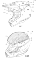
- FIG. 1 depicts an elevational side view of a left side 7 of a powersports helmet 10 according to a non-limiting aspect of the present disclosure.
- the helmet 10 comprises a segmented outer shell or segmented shell 20, an energy management, energy-absorbing, or impact material, layer, or liner 50 disposed within the outer shell 20.
- the helmet 10 may also comprise a visor 12 disposed over, and providing shade to, a faceport 14 in the helmet. While the helmet 10 is shown as a full-face helmet, comprising a chin guard 15 that can define a lower edge of the faceport 14, in some instances, the helmet 10 can be formed without the chin guard 15.
- the chin guard 15 when present, may attach to a main body of the helmet 10 at the A-pillar 16, where the A-pillar defines a rearmost portion of the faceport.
- the energy management liner 50 can comprise one or more materials or layers, such as an outer energy management layer 60 and an inner energy management material or layer 80.
- the outer shell 20 can comprise any materials known in the art of helmets, such as, but not limited to, one or more of ethylene vinyl acetate (EVA) Acrylonitrile butadiene styrene (ABS), polyvinylchloride (PVC), polycarbonate (PC), polyethylene terephthalate (PET), or other plastic, as well as, resin, fiber, fiberglass, carbon fiber, textile, Kevlar TM , or other suitable material, whether cast, formed, molded, stamped, in-molded, injection molded, vacuum formed, or formed by another suitable process.
- EVA ethylene vinyl acetate
- ABS polyvinylchloride
- PC polycarbonate
- PET polyethylene terephthalate
- resin, fiber, fiberglass, carbon fiber, textile, Kevlar TM or other suitable material, whether cast, formed, molded, stamped, in-molded,
- the energy management liner 50 can comprise one or more layers of any materials known in the art of helmets, such as, but not limited to, one or more of plastic, polymer, foam, or other suitable energy absorbing material that can flexibly deform with a hard outer shell to absorb energy and to contribute to energy management without breaking.
- the energy management liner 50 can be one or more layers of expanded polypropylene (EPP) or ethylene vinyl acetate (EVA), which can be used as an energy absorbing and energy attenuating material that is flexible and is able to withstand multiple impacts without being crushed or cracking.
- EPP expanded polypropylene
- EVA ethylene vinyl acetate
- expanded polypropylene (EPP) foam expanded polystyrene (EPS), expanded polyurethane (EPTU or EPU), or expanded polyolefin (EPO) can be used or in-molded to absorb energy from an impact by being crushed or cracked.
- EPP expanded polypropylene
- EPS expanded polystyrene
- EPTU expanded polyurethane
- EPO expanded polyolefin
- a comfort liner or fit liner can be disposed inside the outer shell 20 and inside the energy management liner 50 while being disposed adjacent, and in contact with, the energy management liner 50.
- the comfort liner can be made of textiles, plastic, foam, or other suitable material, such as polyester.
- the comfort liner can be formed of one or more pads of material that can be joined together, or formed as discrete components, that are coupled to the inside of the energy management material, the outer shell, or both.
- the comfort liner can be releasably or permanently coupled to the impact liner using snaps, hook and loop fasteners, adhesives, or other suitable materials or attachment devices. As such, the comfort liner can provide a cushion and improved fit for the wearer of hard shell helmet.
- segmented outer shell 20 of helmet 10 defines or provides elongated segmented openings, gaps, vents, or channels 22 between the upper portion 30 and the lower portion 40.
- the segmented outer shell comprises multiple non-planar segments, such as upper portion 30 and lower portion 40, that form elongated segmented openings 22.
- the elongated segmented openings 22 can be long and continuous while extending between, along, or adjacent, edges of adjacent helmet segments. As shown in FIG.
- the elongated segmented opening 22 extends between, along, and is defined by, an outer or lower edge 32 of the upper portion 30 and an outer or upper edge 42 of the lower portion 40.
- Various views of the edges 32 and 42 are also shown throughout the FIGs., including in FIGs. 4A-4F .
- the elongated segmented openings 22 may extend all the way around, or substantially around (such as 60% or more, 70% or more, 80% or more, or 90% or more) around a circumference or perimeter of the helmet 10 (which may include omitting areas already open such as the faceport 14 when calculating a percentage of perimeter covered by the elongated segmented opening 22).
- a length L of the segmented openings 22 between the forward most portion 11 and the rearward most portion 13 of the segmented openings 22 will be in a range of 1-25 centimeters or 3-25 centimeters (cm) (0.8-10 inches (in.)), 13-25 cm (5-10 in.), or greater than 1 cm, 3 cm, 15 cm, or 20 cm (1.2 in., 6 in. or 8 in.).
- the segmented opening 22 may be positioned as described above, but not connect at a rear of the helmet, or at other portions of the helmet, having the segmented opening being divided into more than one opening, such as two, three, or any other desired number of elongated openings.
- two segmented openings 22 are formed, the two segmented openings 22 being formed as left and right two segmented openings 22 being located on the upper sides of the helmet 10, the left and right segmented openings or vents 22 being separated, e.g., by a piece of the outer shell at the top back of the crown portion of the helmet.
- the segmented opening(s) 22 may begin at an area above or vertically offset from a temple area 18 of the helmet 10 where the helmet 10 covers a temple of the user or wearer of the helmet 10.
- a height H or the separation between helmet segments 30, 40 in the radial direction r can be maintained by one or more reinforcement members or bushings 100 disposed between the upper portion 30 and the lower portion 40 to create the elongated segmented opening 22 in the outer shell 20.
- the elongated segmented opening 22 between portions of the segmented outer shell 20 can be larger in some places than in others, such as comprising a range of heights H that varies along the length or distance of the elongated segmented opening 22 along the helmet 10, from a forward most portion 11 of the elongated segmented opening 22 (at a front of the helmet) to a rearward most portion 13 of the elongated segmented opening 22 (at the back of the helmet 10). As shown in FIG.
- the helmet 10 can pass the penetration test because little or no separation may be present (and overlap O may be present) between portions of the segmented outer shell 20, such as the upper portion 30 and the lower portion 40, that allow for improved airflow in, out, and through the helmet 10.
- the helmet 10 improves upon conventional designs in which small (and short) vent openings (such as with a width of 1 cm and a length of less than 2-3 cm) are exclusively used to prevent the penetration test spike from entering the helmet and causing the helmet to fail the penetration test. To the contrary, and as shown in FIG.
- an increased depth of the energy management liner 50 absorbing energy through deformation, over time, is increased due to increased elastic deformation of the segmented outer shell 20, thereby reducing the energy that is transferred to a center of a test dummy head where force of impact is measured, and by extension reducing an amount of energy transferred to a head of a user.
- the energy management layer 50 By concentrating or absorbing more energy into the energy management layer 50, at a greater depth and for a longer time, which can comprise EPS or other crushable or deformable material, , more of the energy management layer can be crushed leaving less energy to reach and possibly harm the user, all other things being equal.
- the segments of the segmented outer shell 20, such as the upper portion 30 and the lower portion 40 can be coupled or connected, so as to maintain the elongated segmented openings 22 by including a number of reinforcement members 100 between the adjacent shells.
- the reinforcement members 100 can break or snap at a pre-determined or desirable level of energy, or under certain impact conditions, to assist in absorbing and managing impact energy. In other instances, the reinforcement members can remain unbroken to ensure stability of the outer shell.
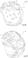
- the outer energy management layer 60 comprises openings 62 that extend completely through the outer energy management layer 60, extending form the inner surface 68 to the outer surface 70.
- the openings 62 can be smaller or have a footprint or area that is less than the size, footprint, or area of the channels 82 of the inner energy management layer 80.
- the outer surface 70 is formed as an uneven surface comprising raised portions standoffs or pillars 64, and recessed portions, grooves, or channels 66, which encourage and channel airflow F through the helmet in desired ways, such as from the interior 19 out through the elongated segmented openings 22 to increase ventilation and improve cooling for the user.
- FIG. 2C shows another perspective view of the outer energy management layer 60 similar to that of FIG. 2B , but instead is shown from below and in front of the outer energy management layer 60.
- FIG. 2C shows additional detail of the uneven, or stepped outer surface 70 of the outer energy management layer 60 that can comprise stand-offs, ridges, pillars, bumps, columns, or protrusions 64 that can directly contact the outer shell 20 in some places, while not extending to touch the outer shell 20 in other places, allowing the airflow F to vent to the elongated segmented openings 22 in the outer shell 20.
- FIGs. 3A-3D show the outer energy management layer shown in FIGs. 2B and 2C included within a full helmet, and various cut-way views of the helmet.
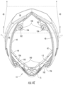
- FIG. 3A shows a cross-sectional side view taken along a center, sagittal, or median plane of the helmet 10, with the front 8 of the helmet 10 being shown on the left of the figure and the rear 9 of the helmet 10 being shown on the right of the figure.
- FIG. 3A shows a cross-sectional side view taken along a center, sagittal, or median plane of the helmet 10, with the front 8 of the helmet 10 being shown on the left of the figure and the rear 9 of the helmet 10 being shown on the right of the figure.
- FIG. 3A shows a cross-sectional side view taken along a center, sagittal, or median plane of the helmet 10, with the front 8 of the helmet 10 being shown on the left of the figure and the rear 9 of the helmet 10 being shown on the right of the figure.
- FIG. 3A shows a cross-sectional side view taken
- 3A also shows the airflow F as a plurality of arrows representing flow paths and airflow through the helmet 10 that enter at the front 8 of the helmet, such as through front air intake vents 6 and through the faceport 14, may travel along the interior of the helmet 19, and may then pass through, or enter directly into, a plurality of airflow channels 82 in the inner energy management layer 80, through openings 62, and out the elongated segmented opening 22 in the outer shell 20.
- a temperature of the air around and through the helmet 10 can change as the flow F interacts with the user's head and hair and pulls undesired or excess heat away from the head of the user.
- 3A can be cool air that enters and circulates through the helmet, and the flow F at the rear 9 of the helmet 10, or at the right of the helmet 10 can be warmer or hotter air, as the flow F has evacuated, pulled, or transported heat away from the head of the user.
- FIG. 3A also shows that the airflow F through the helmet 10 can be aided, assisted, or facilitated by the shape or structure of the energy management layer 50.
- the inner energy management layer 80 can be inwardly disposed with respect to the outer energy management layer 60, where, for convenience, the FIGs. show the outer energy management layer 60 with cross-hatching.
- the inner energy management layer 80 comprises a plurality of elongated channels 82, and a series of fingers or ribs 83 disposed between and defined at least in part by the channels 82.
- the channels 82 form a part of the paths of the flow F of air through the helmet 10.
- the airflow F need not pass through indirect or circuitous pathways, nor does the airflow F need to pass through a simple hole or opening that extends radially from an outer surface 36, 46 of the helmet 10 to the interior 19 of the helmet 10 (with a line of sight directly to the head of the user. Instead, the airflow F can pass smoothly and directly around a user's head at the interior 19 of the helmet 10 and through the energy management liner 50 and segmented outer shell 20 in smooth provide elongated flows that increase the interface between the airflow F within the helmet 10 and the head of the user for prolonged contact and improved heat transfer.
- the elongated channels 82 formed within the inner energy management layer 80 may extend from the front 8 to the back 9 of the helmet 10, which differ from conventional power sport helmets, which have comprised openings of small sizes, such as lengths less than 2-3 cm, an circular openings with diameters of 5-10 mm that extend with a clear line of sight, a radial direction, from the outer surface of the helmet to the user's head.
- conventional power sport helmets which have comprised openings of small sizes, such as lengths less than 2-3 cm, an circular openings with diameters of 5-10 mm that extend with a clear line of sight, a radial direction, from the outer surface of the helmet to the user's head.
- the size of the conventional powersports helmet openings has remained small to ensure performance during puncture test, which has limited airflow through the helmet.
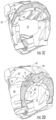
- FIG. 3B shows a perspective interior cut-away view of the front and interior of an embodiment of the helmet 10 with the chin guard 15 removed so that the energy management liner 50, including the outer energy management layer 60 and the inner energy management layer 80 inside the segmented outer shell 20 are visible.
- the inner energy management layer 80 may comprise ribs or fingers 83 and elongated channels 82. At least a portion of the channels 82 may be in contact with, or open to, the head of the helmet wearer so that the airflow F will be in increased contact with the wearer's head, facilitating increased evaporation and cooling.
- Positions of the front intake vents 6 and the elongated segmented opening 22 shown in the FIGs. have provided desirable results in testing, and good performance.
- the user can place plugs or stoppers made of rubber, plastic, or other suitable material into the intake vents 6, elongated segmented opening 22, or both, to limit the airflow through the airflow channels and reduce cooling and ventilation through the helmet.
- FIG. 3C shows a perspective interior cut-away view from the rear 9 or behind the helmet to show a cross-sectional view of the energy management layers 60, 80 inside the helmet 10, and their interaction for facilitating the airflow F through the helmet 10 to the elongated segmented opening 22 in the outer shell 20.
- the comfort padding can be placed along the fingers or ribs 83 of the inner energy management layer 80 so that the airflow F is not blocked or impeded by the comfort padding.
- Applicant have discovered that even mesh or fabrics and textiles with openings as part of the comfort padding that extends over the channels 82 can significantly diminish airflow and cooling.
- FIG. 3D similar to FIG. 3C , shows another perspective cut-away view from the rear 9 or from behind the helmet 10 so that the energy management liner 50 inside the helmet, and the pathways for the airflow F through the helmet to the elongated segmented opening 22 in the outer shell 20 are visible.
- FIG. 4A shows a cross-sectional side view of the entire segmented outer shell 20 of the helmet 10 comprising the upper portion 30 coupled to the lower portion 40 of the outer shell 20.
- a reinforcement member 100 can be disposed between the upper portion 30 and the lower portion 40 of the shell 20.
- the reinforcement members 100 may be formed as bushings or sleeves comprising a flattened top portion 102 and a smaller stem portion 104, together forming a mushroom type shape.
- the reinforcement members 100 may be formed as bushings with a generally circular or tubular shape and may further comprise an opening or channel 106, which can also be circular, passing through an axis or a center of the reinforcement member 100, including booth the top portion 102 and the stem portion 104.
- the opening 106 can be for receiving a pin, rod, spindle, pinion, post, pillar, or stud 110, to couple the reinforcement member 100 between segments of the segmented outer shell 20, such as segments 30, 40 of the helmet 10.
- the reinforcement members 100 may not be formed as bushings per se, but may be formed as vertical offset members, such as with an opening 106 for receiving pins 110 or other similar structures that are coupled, or directly attached, to an inner surface 34 of the upper portion 30 of the segmented outer shell 20, or an inner surface 44 of the lower portion 40 of the segmented outer shell 20.
- the reinforcement members 100 can be formed of a same material and at a same time of as the segmented outer shell 20.
- the outer shell 20 can, in some instances, still be formed as unitary outer shell, although with a non-uniformly planar surface, and elongated segmented openings 22.
- the reinforcement members 100 may be formed of a material that is different than, the material of the outer shell 20, such as a softer more deformable material, including rubber, phenolic, plastic, fiberglass, or other suitable material capable to handle manufacturing tolerances, provide flexible support and a buffer for the outer shell 20.
- FIG. 4B shows a cross-sectional view transverse or perpendicular to the cross-section view shown in FIG. 4A .
- FIB. 4B shows some of the upper portion 30 and some of the lower portion 40 of the segmented outer shell 20 with a reinforcement member 100 disposed between the upper portion 30 and the lower portion 40.
- the reinforcement members 100 may be formed with a mushroom shape comprising a flattened top portion 102 and a lower stem portion 104, wherein the top portion 102 comprises an area or footprint larger than an area or footprint of the lower stem portion 104.
- the central opening 106 may extend through the flattened portion 102 and the stem portion 104, and be sized to receive a pin, rod, spindle, pinion, post, pillar, or stud 110.
- the pin 110 may be formed of a unitary construction with either the upper portion 30 of the segmented outer shell 20 or the lower portion 40 of the segmented outer shell 20. As such, the pin 110 may be integrally formed or molded as a single, unitary, or mono-formed piece and at a same time or in a same process as the formation or molding of the shell 20, or a portion of the shell 20, such as the upper portion 30 or the lower portion 40 of the segmented outer shell 20.
- the pin 110 may be formed separately from, and be later joined with, a portion of the helmet 10, such as with either the upper portion 30 or the lower portion 40 of the segmented outer shell 20, so that the pin 110 is not of a unitary construction or mono-formed.
- FIG. 4C shows a top-down perspective view of the lower portion 40 of the segmented outer shell 20 with four reinforcement members 100 disposed on four corresponding tabs or flanges 43 of the lower portion 40. While four tabs 43 are shown, two at a front 8 of the helmet 10 and two at the rear 9 of the helmet, any desirable number of tabs 43 and corresponding reinforcement members 100 may be used. However, the number and location of tabs 43 and corresponding reinforcement members 100 shown have been found desirable.
- the tabs 43 may comprise openings 45 that can align with opening 106 in reinforcement members 100 which together can receive pin 110 or other suitable locking or securing member for coupling segments 30, 40 of the segmented outer shell 20 to each other.
- FIG. 4D shows a bottom-up view of a rear piece of the lower portion 40 of the shell 20 taken along the section line 4D-4D shown in in FIG. 4C .
- FIG. 4D also shows two rear reinforcement members 100 for coupling the upper portion of the segmented outer shell 30 to the lower portion 40 of the segmented outer shell 20.
- FIG. 4E shows a bottom view of the upper portion of the segmented outer shell 30 with four reinforcement members 100 coupled to pins 110, corresponding to, and being configured to be mateably coupled with, the lower portion of the segmented lower shell 40 shown in in FIG. 4C . While both FIGs. 4C and 4E have shown, for reference, the positions of the reinforcement members 100 with respect to the segmented outer shell 20, when the upper portion 30 is coupled to the lower portion 40, only one reinforcement member 100 per position may be used. However, in other instances, multiple reinforcement member 100 of varying shape, design, material, strength, and elasticity, may be used in conjunction with one another, such as by being stacked or interconnected.
- FIG. 4F shows a side elevational view of a top section of the side 7 of the lower portion 40 of the segmented lower shell 20.
- FIG. 4F also shows front and rear reinforcement members 100 disposed on tabs 43.
Landscapes
- Helmets And Other Head Coverings (AREA)
Claims (14)
- Un casque (10) comprenant :une coque externe (20) segmentée comprenant une portion supérieure (30) et une portion inférieure (40), et définissant des ouvertures segmentées allongées (22) droite et gauche qui s'étendent le long d'une interface (32, 42) des portions supérieure et inférieure s'étendant à partir de montants a (16) sur les côtés droit et gauche d'un orifice pour le visage jusqu'à un arrière du casque ;une doublure de gestion d'énergie (50) disposée au sein de la coque externe segmentée et comprenant en outre :une couche externe de gestion d'énergie (60) comprenant des ouvertures (62) formées complètement à travers la couche externe de gestion d'énergie et ayant une surface externe (70) irrégulière ou étagée comprenant des écarteurs, des stries, des montants, des bosses, des colonnes, ou des saillies (64) de sorte que la surface externe (70) entre directement en contact avec la coque externe (20) en certains endroits tout en ne s'étendant pas jusqu'à toucher la coque externe segmentée en d'autres endroits, etune couche interne de gestion d'énergie (80) disposée au sein de la couche externe de gestion d'énergie (60), la couche interne de gestion d'énergie comprenant des canaux (82) formés complètement à travers la couche interne de gestion d'énergie (80) qui sont alignés, et se chevauchent sur au moins 1 centimètre (cm), avec les ouvertures (62) dans la couche externe de gestion d'énergie (60) et facilitent une circulation d'air à travers les ouvertures segmentées allongées (22).
- Le casque (10) de la revendication 1, dans lequel les ouvertures segmentées allongées (22) présentent une longueur comprise dans la gamme allant de 1 cm à 20 cm.
- Le casque (10) de la revendication 1, dans lequel les ouvertures segmentées allongées (22) présentent une longueur supérieure à 3 cm et une hauteur allant de 0,2 à 1,5 cm sans qu'une ligne de visée radiale soit formée à partir de l'extérieur du casque jusqu'à la doublure de gestion d'énergie (50).
- Le casque (10) de la revendication 1, dans lequel :la portion supérieure (30) de la coque externe (20) segmentée recouvre un dessus et la calotte du casque ; etla portion inférieure (40) de la coque externe (20) segmentée recouvre le côté et l'arrière du casque.
- Le casque (10) de la revendication 1 comprenant un organe de renfort (100) disposé entre la portion supérieure (30) et la portion inférieure (40) afin de créer les ouvertures segmentées allongées (22) dans la coque externe.
- Le casque (10) de la revendication 5, dans lequel l'organe de renfort (100) est formé en tant que douille avec une forme généralement circulaire ou tubulaire.
- Le casque (10) de la revendication 5, dans lequel l'organe de renfort (100) est réalisé dans un matériau plus mou et plus déformable que la coque externe.
- Le casque (10) de la revendication 5, dans lequel l'organe de renfort (100) est formé dans le même matériau et en même temps que la coque externe segmentée.
- Le casque (10) des revendications 5 à 8, dans lequel l'organe de renfort (100) comprend une ouverture (106) pour recevoir une broche (110) formée en une structure unitaire avec soit la portion inférieure (40), soit la portion supérieure (30) de la coque externe segmentée.
- Le casque (10) de la revendication 5, dans lequel l'organe de renfort (100) est formé en tant que douille accouplée à une broche (110) formée en une structure unitaire avec soit la portion supérieure (30) de la coque externe segmentée, soit la portion inférieure (40) de la coque externe segmentée.
- Le casque (10) de la revendication 5, dans lequel l'organe de renfort (100) est formé avec une forme de champignon comprenant une portion de dessus aplatie (102) et une portion tige inférieure (104), dans lequel la portion de dessus (102) comprend une zone ou empreinte plus grande qu'une zone ou empreinte de la portion tige inférieure (104).
- Le casque (10) de la revendication 5, dans lequel :la couche externe de gestion d'énergie (60) est formée de polystyrène expansé (PSE) ; etla couche interne de gestion d'énergie (80) est formée de polypropylène expansé (PPE).
- Le casque (10) des revendications 1 à 4, dans lequel les canaux (82) s'étendent à partir du devant (8) jusqu'au dos (9) du casque (10).
- Le casque (10) de la revendication 5, dans lequel l'organe de renfort (100) est formé en tant que douille accouplée à une broche (110) formée séparément de et assemblée à soit la portion supérieure (30), soit la portion inférieure (40) de la coque externe (20) segmentée.
Applications Claiming Priority (3)
| Application Number | Priority Date | Filing Date | Title |
|---|---|---|---|
| US201762450703P | 2017-01-26 | 2017-01-26 | |
| US15/880,475 US10602795B2 (en) | 2017-01-26 | 2018-01-25 | Helmet comprising a segmented shell |
| PCT/US2018/015542 WO2018140787A1 (fr) | 2017-01-26 | 2018-01-26 | Casque comprenant une coque segmentée |
Publications (3)
| Publication Number | Publication Date |
|---|---|
| EP3558045A1 EP3558045A1 (fr) | 2019-10-30 |
| EP3558045A4 EP3558045A4 (fr) | 2021-01-06 |
| EP3558045B1 true EP3558045B1 (fr) | 2025-03-26 |
Family
ID=62905714
Family Applications (1)
| Application Number | Title | Priority Date | Filing Date |
|---|---|---|---|
| EP18745472.3A Active EP3558045B1 (fr) | 2017-01-26 | 2018-01-26 | Casque comprenant une coque segmentée |
Country Status (4)
| Country | Link |
|---|---|
| US (3) | US10602795B2 (fr) |
| EP (1) | EP3558045B1 (fr) |
| CN (1) | CN110381763B (fr) |
| WO (1) | WO2018140787A1 (fr) |
Families Citing this family (22)
| Publication number | Priority date | Publication date | Assignee | Title |
|---|---|---|---|---|
| US10602795B2 (en) * | 2017-01-26 | 2020-03-31 | Bell Sports, Inc. | Helmet comprising a segmented shell |
| CA3002065A1 (fr) | 2017-04-18 | 2018-10-18 | Kimpex Inc. | Casque aere empechant le depot de buee sur une lunette protectrice, et methode et utilisation dudit casque |
| US10398187B1 (en) * | 2017-06-13 | 2019-09-03 | Bell Sports, Inc | Adjustable elastomeric helmet multi-liner retainer and method of assembling multi-liner helmet |
| USD967543S1 (en) * | 2018-01-25 | 2022-10-18 | Bell Sports, Inc. | Helmet with integrated shoulder pad |
| USD908971S1 (en) * | 2018-07-20 | 2021-01-26 | Hjc Corp. | Helmet |
| US12004584B2 (en) | 2018-11-02 | 2024-06-11 | Zam Helmets Inc. | Protective headgear with integrally-formed layer |
| USD953647S1 (en) * | 2019-04-12 | 2022-05-31 | 100% Speedlab, Llc | Helmet |
| USD959752S1 (en) * | 2019-06-20 | 2022-08-02 | Locateli S.p.A. | Helmet |
| USD949483S1 (en) * | 2019-08-05 | 2022-04-19 | H&H Sports Protection S.R.L. | Protective helmet |
| ES2924129T3 (es) * | 2019-12-18 | 2022-10-04 | George Tfe Scp | Casco |
| CA3177316A1 (fr) | 2020-05-12 | 2021-11-18 | Joseph R. WORPLE | Casque de protection dote d'un materiau de protection contre les chocs |
| USD977198S1 (en) | 2020-06-23 | 2023-01-31 | Bell Sports, Inc. | Helmet |
| USD974704S1 (en) * | 2021-03-10 | 2023-01-10 | H&H Sports Protection S.R.L. | Helmet |
| JP1733278S (ja) * | 2022-01-20 | 2022-12-27 | バイク用ヘルメット | |
| USD1121893S1 (en) * | 2022-08-03 | 2026-04-07 | Bell Sports, Inc. | Helmet |
| USD1121892S1 (en) * | 2022-10-28 | 2026-04-07 | Fox Head, Inc. | Helmet |
| USD1102040S1 (en) * | 2023-02-27 | 2025-11-11 | Fox Head, Inc. | Helmet |
| USD1122529S1 (en) * | 2023-05-08 | 2026-04-14 | Hjc Corp. | Helmet |
| USD1115181S1 (en) * | 2023-05-10 | 2026-02-24 | Bell Sports, Inc. | Helmet with cheek pads |
| USD1094899S1 (en) * | 2023-08-22 | 2025-09-23 | Liding Tang | Motorcycle helmet |
| USD1050612S1 (en) | 2024-02-02 | 2024-11-05 | Dongguan City Hongtu Sporting Goods Co., Ltd. | Bicycle helmet |
| USD1111320S1 (en) * | 2024-07-24 | 2026-02-10 | Henry Tedjakusuma | Helmet |
Family Cites Families (35)
| Publication number | Priority date | Publication date | Assignee | Title |
|---|---|---|---|---|
| US4434514A (en) * | 1982-01-07 | 1984-03-06 | Bell Helmets Inc. | Bicyclists helmet with air flow and perspiration control |
| US4622700A (en) * | 1985-12-09 | 1986-11-18 | Bell Helmets Inc. | Suction ventilated helmet |
| EP0351407A4 (en) | 1987-03-05 | 1990-12-27 | Ricky James Gath | Safety helmet |
| GB2219728B (en) | 1988-06-20 | 1992-07-29 | Britax Child Care Prod | Safety helmet |
| DE9212247U1 (de) * | 1992-09-11 | 1993-04-08 | F. M. Fallert Motor GmbH & Co, Motorrad-Sport KG, 7590 Achern | Sturzhelm mit einer körpergerechten Polsterung und Vorrichtung zu deren Herstellung |
| US5394566A (en) * | 1993-12-14 | 1995-03-07 | Hong Jin Crown America, Inc. | Cold weather ventilation system for faceshield defogging |
| US5888973A (en) | 1996-08-09 | 1999-03-30 | Xoma Corporation | Anti-chlamydial uses of BPI protein products |
| JP2962700B2 (ja) * | 1998-01-22 | 1999-10-12 | オージーケー販売株式会社 | ヘルメット装置 |
| EP1016352A1 (fr) | 1998-12-31 | 2000-07-05 | Camau System di Casale & C. s.n.c. | Casque muni d'une calotte intérieure à densité multiple |
| DE20203477U1 (de) * | 2002-03-05 | 2002-05-29 | Schuberth Werk GmbH, 38106 Braunschweig | Sturzhelm |
| FR2865356B1 (fr) * | 2004-01-28 | 2007-01-12 | Des Ouches Pascal Joubert | Casque de protection semi-rigide |
| US7111329B2 (en) | 2004-06-29 | 2006-09-26 | Bell Sports, Inc. | Helmet reinforcement system |
| US7000262B2 (en) * | 2004-07-26 | 2006-02-21 | E.D. Bullard Company | Flexible ratchet mechanism for the headband of protective headgear |
| US20060031978A1 (en) * | 2004-08-10 | 2006-02-16 | Pierce Brendan E | Ventilated helmet system |
| US7114197B2 (en) | 2005-01-14 | 2006-10-03 | Louis Garneau Sport Inc. | Adjustable stabilization strap apparatus |
| US7895681B2 (en) * | 2006-02-16 | 2011-03-01 | Xenith, Llc | Protective structure and method of making same |
| US9289024B2 (en) | 2007-04-16 | 2016-03-22 | Riddell, Inc. | Protective sports helmet |
| CA2659638C (fr) * | 2008-03-21 | 2013-07-23 | Mission Itech Hockey Ltd. | Casque pour joueur de hockey ou de crosse |
| CA2784316C (fr) * | 2011-07-27 | 2013-10-01 | Bauer Hockey Corp. | Casque de sport avec protection contre les impacts par rotation |
| EP2550882B1 (fr) * | 2011-07-27 | 2019-08-21 | Bauer Hockey Ltd. | Casque de sport |
| US9414636B2 (en) * | 2012-04-06 | 2016-08-16 | Bell Sports, Inc. | Protective bicycle helmet with internal ventilation system |
| US9314063B2 (en) | 2013-02-12 | 2016-04-19 | Riddell, Inc. | Football helmet with impact attenuation system |
| US9545125B2 (en) | 2013-03-25 | 2017-01-17 | Sebastian Yoon | Magnetic segmented sport equipment |
| JP6286137B2 (ja) * | 2013-05-13 | 2018-02-28 | 東洋物産工業株式会社 | 作業用ヘルメットにおける衝撃吸収ライナ |
| ITMI20130978A1 (it) * | 2013-06-13 | 2014-12-14 | Kask S R L | Casco a ventilazione selettiva per uso ciclistico |
| CA2929623C (fr) * | 2013-12-06 | 2024-02-20 | Bell Sports, Inc. | Casque flexible a plusieurs couches et procede de fabrication de celui-ci |
| US9693594B1 (en) * | 2014-02-18 | 2017-07-04 | Harvest Moon Inventions, LLC | Protective headgear |
| FR3020560B1 (fr) * | 2014-04-30 | 2016-05-27 | Atomic Austria Gmbh | Casque adapte aux contraintes de son utilisation |
| CA2970532A1 (fr) * | 2015-01-07 | 2016-07-14 | The Uab Research Foundation, Inc. | Systemes de casque de protection qui permettent au casque de tourner independamment de la tete |
| ITUB20155310A1 (it) * | 2015-10-27 | 2017-04-27 | Kask Spa | Fascia poggia fronte per caschi e casco provvisto di tale fascia poggia fronte. |
| US10376010B2 (en) * | 2015-11-04 | 2019-08-13 | Bell Sports, Inc. | Shock absorbing helmet |
| US10271603B2 (en) * | 2016-04-12 | 2019-04-30 | Bell Sports, Inc. | Protective helmet with multiple pseudo-spherical energy management liners |
| US10602795B2 (en) * | 2017-01-26 | 2020-03-31 | Bell Sports, Inc. | Helmet comprising a segmented shell |
| CA3002065A1 (fr) * | 2017-04-18 | 2018-10-18 | Kimpex Inc. | Casque aere empechant le depot de buee sur une lunette protectrice, et methode et utilisation dudit casque |
| FR3069418B1 (fr) * | 2017-07-26 | 2019-11-29 | Skis Rossignol - Club Rossignol | Casque de sport a capacites d’aeration et de desembuage renforcees |
-
2018
- 2018-01-25 US US15/880,475 patent/US10602795B2/en active Active
- 2018-01-26 WO PCT/US2018/015542 patent/WO2018140787A1/fr not_active Ceased
- 2018-01-26 CN CN201880008228.1A patent/CN110381763B/zh active Active
- 2018-01-26 EP EP18745472.3A patent/EP3558045B1/fr active Active
-
2020
- 2020-02-20 US US16/796,661 patent/US11213090B2/en active Active
-
2021
- 2021-12-09 US US17/547,110 patent/US11839257B2/en active Active
Also Published As
| Publication number | Publication date |
|---|---|
| CN110381763A (zh) | 2019-10-25 |
| EP3558045A4 (fr) | 2021-01-06 |
| US20200329804A1 (en) | 2020-10-22 |
| WO2018140787A1 (fr) | 2018-08-02 |
| EP3558045A1 (fr) | 2019-10-30 |
| US11839257B2 (en) | 2023-12-12 |
| US20220095737A1 (en) | 2022-03-31 |
| US20180206584A1 (en) | 2018-07-26 |
| US10602795B2 (en) | 2020-03-31 |
| US11213090B2 (en) | 2022-01-04 |
| CN110381763B (zh) | 2022-04-22 |
Similar Documents
| Publication | Publication Date | Title |
|---|---|---|
| US11839257B2 (en) | Helmet comprising a segmented shell | |
| US11812815B2 (en) | In-molded helmet chinbar | |
| US7987525B2 (en) | Helmet | |
| US9107466B2 (en) | Batting helmet having localized impact protection | |
| EP3116339B1 (fr) | Casque à ajustement adaptatif, et procédé pour monter un casque sur une tête de client | |
| US10918153B2 (en) | Helmet with airflow ventilation through an earpad | |
| US10376010B2 (en) | Shock absorbing helmet | |
| US9872532B2 (en) | Sweat management pad for protective helmets | |
| EP1611809A1 (fr) | Casque muni d'un système de renforcement | |
| EP3558044B1 (fr) | Casque avec rembourrage pour épaules intégré | |
| EP3586662B1 (fr) | Casque comportant un évent d'air à commande magnétique |
Legal Events
| Date | Code | Title | Description |
|---|---|---|---|
| STAA | Information on the status of an ep patent application or granted ep patent |
Free format text: STATUS: THE INTERNATIONAL PUBLICATION HAS BEEN MADE |
|
| PUAI | Public reference made under article 153(3) epc to a published international application that has entered the european phase |
Free format text: ORIGINAL CODE: 0009012 |
|
| STAA | Information on the status of an ep patent application or granted ep patent |
Free format text: STATUS: REQUEST FOR EXAMINATION WAS MADE |
|
| 17P | Request for examination filed |
Effective date: 20190724 |
|
| AK | Designated contracting states |
Kind code of ref document: A1 Designated state(s): AL AT BE BG CH CY CZ DE DK EE ES FI FR GB GR HR HU IE IS IT LI LT LU LV MC MK MT NL NO PL PT RO RS SE SI SK SM TR |
|
| AX | Request for extension of the european patent |
Extension state: BA ME |
|
| DAV | Request for validation of the european patent (deleted) | ||
| DAX | Request for extension of the european patent (deleted) | ||
| REG | Reference to a national code |
Ref country code: DE Ref legal event code: R079 Free format text: PREVIOUS MAIN CLASS: A42B0003040000 Ipc: A42B0003280000 |
|
| A4 | Supplementary search report drawn up and despatched |
Effective date: 20201209 |
|
| RIC1 | Information provided on ipc code assigned before grant |
Ipc: A42B 3/32 20060101ALI20201203BHEP Ipc: A42B 3/28 20060101AFI20201203BHEP Ipc: A42B 3/12 20060101ALI20201203BHEP Ipc: A42B 3/06 20060101ALI20201203BHEP |
|
| STAA | Information on the status of an ep patent application or granted ep patent |
Free format text: STATUS: EXAMINATION IS IN PROGRESS |
|
| 17Q | First examination report despatched |
Effective date: 20221108 |
|
| GRAP | Despatch of communication of intention to grant a patent |
Free format text: ORIGINAL CODE: EPIDOSNIGR1 |
|
| STAA | Information on the status of an ep patent application or granted ep patent |
Free format text: STATUS: GRANT OF PATENT IS INTENDED |
|
| INTG | Intention to grant announced |
Effective date: 20241017 |
|
| GRAS | Grant fee paid |
Free format text: ORIGINAL CODE: EPIDOSNIGR3 |
|
| GRAA | (expected) grant |
Free format text: ORIGINAL CODE: 0009210 |
|
| STAA | Information on the status of an ep patent application or granted ep patent |
Free format text: STATUS: THE PATENT HAS BEEN GRANTED |
|
| AK | Designated contracting states |
Kind code of ref document: B1 Designated state(s): AL AT BE BG CH CY CZ DE DK EE ES FI FR GB GR HR HU IE IS IT LI LT LU LV MC MK MT NL NO PL PT RO RS SE SI SK SM TR |
|
| REG | Reference to a national code |
Ref country code: GB Ref legal event code: FG4D |
|
| REG | Reference to a national code |
Ref country code: CH Ref legal event code: EP |
|
| REG | Reference to a national code |
Ref country code: DE Ref legal event code: R096 Ref document number: 602018080457 Country of ref document: DE |
|
| REG | Reference to a national code |
Ref country code: IE Ref legal event code: FG4D |
|
| PG25 | Lapsed in a contracting state [announced via postgrant information from national office to epo] |
Ref country code: RS Free format text: LAPSE BECAUSE OF FAILURE TO SUBMIT A TRANSLATION OF THE DESCRIPTION OR TO PAY THE FEE WITHIN THE PRESCRIBED TIME-LIMIT Effective date: 20250626 |
|
| PG25 | Lapsed in a contracting state [announced via postgrant information from national office to epo] |
Ref country code: FI Free format text: LAPSE BECAUSE OF FAILURE TO SUBMIT A TRANSLATION OF THE DESCRIPTION OR TO PAY THE FEE WITHIN THE PRESCRIBED TIME-LIMIT Effective date: 20250326 |
|
| REG | Reference to a national code |
Ref country code: LT Ref legal event code: MG9D |
|
| PG25 | Lapsed in a contracting state [announced via postgrant information from national office to epo] |
Ref country code: NO Free format text: LAPSE BECAUSE OF FAILURE TO SUBMIT A TRANSLATION OF THE DESCRIPTION OR TO PAY THE FEE WITHIN THE PRESCRIBED TIME-LIMIT Effective date: 20250626 |
|
| PG25 | Lapsed in a contracting state [announced via postgrant information from national office to epo] |
Ref country code: HR Free format text: LAPSE BECAUSE OF FAILURE TO SUBMIT A TRANSLATION OF THE DESCRIPTION OR TO PAY THE FEE WITHIN THE PRESCRIBED TIME-LIMIT Effective date: 20250326 |
|
| PG25 | Lapsed in a contracting state [announced via postgrant information from national office to epo] |
Ref country code: LV Free format text: LAPSE BECAUSE OF FAILURE TO SUBMIT A TRANSLATION OF THE DESCRIPTION OR TO PAY THE FEE WITHIN THE PRESCRIBED TIME-LIMIT Effective date: 20250326 |
|
| PG25 | Lapsed in a contracting state [announced via postgrant information from national office to epo] |
Ref country code: GR Free format text: LAPSE BECAUSE OF FAILURE TO SUBMIT A TRANSLATION OF THE DESCRIPTION OR TO PAY THE FEE WITHIN THE PRESCRIBED TIME-LIMIT Effective date: 20250627 Ref country code: BG Free format text: LAPSE BECAUSE OF FAILURE TO SUBMIT A TRANSLATION OF THE DESCRIPTION OR TO PAY THE FEE WITHIN THE PRESCRIBED TIME-LIMIT Effective date: 20250326 |
|
| REG | Reference to a national code |
Ref country code: NL Ref legal event code: MP Effective date: 20250326 |
|
| PG25 | Lapsed in a contracting state [announced via postgrant information from national office to epo] |
Ref country code: NL Free format text: LAPSE BECAUSE OF FAILURE TO SUBMIT A TRANSLATION OF THE DESCRIPTION OR TO PAY THE FEE WITHIN THE PRESCRIBED TIME-LIMIT Effective date: 20250326 |
|
| PG25 | Lapsed in a contracting state [announced via postgrant information from national office to epo] |
Ref country code: SE Free format text: LAPSE BECAUSE OF FAILURE TO SUBMIT A TRANSLATION OF THE DESCRIPTION OR TO PAY THE FEE WITHIN THE PRESCRIBED TIME-LIMIT Effective date: 20250326 |
|
| REG | Reference to a national code |
Ref country code: AT Ref legal event code: MK05 Ref document number: 1778143 Country of ref document: AT Kind code of ref document: T Effective date: 20250326 |
|
| PG25 | Lapsed in a contracting state [announced via postgrant information from national office to epo] |
Ref country code: SM Free format text: LAPSE BECAUSE OF FAILURE TO SUBMIT A TRANSLATION OF THE DESCRIPTION OR TO PAY THE FEE WITHIN THE PRESCRIBED TIME-LIMIT Effective date: 20250326 |
|
| PG25 | Lapsed in a contracting state [announced via postgrant information from national office to epo] |
Ref country code: ES Free format text: LAPSE BECAUSE OF FAILURE TO SUBMIT A TRANSLATION OF THE DESCRIPTION OR TO PAY THE FEE WITHIN THE PRESCRIBED TIME-LIMIT Effective date: 20250326 Ref country code: PT Free format text: LAPSE BECAUSE OF FAILURE TO SUBMIT A TRANSLATION OF THE DESCRIPTION OR TO PAY THE FEE WITHIN THE PRESCRIBED TIME-LIMIT Effective date: 20250728 |
|
| PG25 | Lapsed in a contracting state [announced via postgrant information from national office to epo] |
Ref country code: IT Free format text: LAPSE BECAUSE OF FAILURE TO SUBMIT A TRANSLATION OF THE DESCRIPTION OR TO PAY THE FEE WITHIN THE PRESCRIBED TIME-LIMIT Effective date: 20250326 Ref country code: PL Free format text: LAPSE BECAUSE OF FAILURE TO SUBMIT A TRANSLATION OF THE DESCRIPTION OR TO PAY THE FEE WITHIN THE PRESCRIBED TIME-LIMIT Effective date: 20250326 |
|
| PG25 | Lapsed in a contracting state [announced via postgrant information from national office to epo] |
Ref country code: AT Free format text: LAPSE BECAUSE OF FAILURE TO SUBMIT A TRANSLATION OF THE DESCRIPTION OR TO PAY THE FEE WITHIN THE PRESCRIBED TIME-LIMIT Effective date: 20250326 |
|
| PG25 | Lapsed in a contracting state [announced via postgrant information from national office to epo] |
Ref country code: EE Free format text: LAPSE BECAUSE OF FAILURE TO SUBMIT A TRANSLATION OF THE DESCRIPTION OR TO PAY THE FEE WITHIN THE PRESCRIBED TIME-LIMIT Effective date: 20250326 |
|
| PG25 | Lapsed in a contracting state [announced via postgrant information from national office to epo] |
Ref country code: RO Free format text: LAPSE BECAUSE OF FAILURE TO SUBMIT A TRANSLATION OF THE DESCRIPTION OR TO PAY THE FEE WITHIN THE PRESCRIBED TIME-LIMIT Effective date: 20250326 |
|
| PG25 | Lapsed in a contracting state [announced via postgrant information from national office to epo] |
Ref country code: SK Free format text: LAPSE BECAUSE OF FAILURE TO SUBMIT A TRANSLATION OF THE DESCRIPTION OR TO PAY THE FEE WITHIN THE PRESCRIBED TIME-LIMIT Effective date: 20250326 |
|
| PG25 | Lapsed in a contracting state [announced via postgrant information from national office to epo] |
Ref country code: IS Free format text: LAPSE BECAUSE OF FAILURE TO SUBMIT A TRANSLATION OF THE DESCRIPTION OR TO PAY THE FEE WITHIN THE PRESCRIBED TIME-LIMIT Effective date: 20250726 |
|
| REG | Reference to a national code |
Ref country code: DE Ref legal event code: R097 Ref document number: 602018080457 Country of ref document: DE |
|
| PG25 | Lapsed in a contracting state [announced via postgrant information from national office to epo] |
Ref country code: DK Free format text: LAPSE BECAUSE OF FAILURE TO SUBMIT A TRANSLATION OF THE DESCRIPTION OR TO PAY THE FEE WITHIN THE PRESCRIBED TIME-LIMIT Effective date: 20250326 |
|
| PG25 | Lapsed in a contracting state [announced via postgrant information from national office to epo] |
Ref country code: CZ Free format text: LAPSE BECAUSE OF FAILURE TO SUBMIT A TRANSLATION OF THE DESCRIPTION OR TO PAY THE FEE WITHIN THE PRESCRIBED TIME-LIMIT Effective date: 20250326 |
|
| PLBE | No opposition filed within time limit |
Free format text: ORIGINAL CODE: 0009261 |
|
| STAA | Information on the status of an ep patent application or granted ep patent |
Free format text: STATUS: NO OPPOSITION FILED WITHIN TIME LIMIT |
|
| REG | Reference to a national code |
Ref country code: CH Ref legal event code: L10 Free format text: ST27 STATUS EVENT CODE: U-0-0-L10-L00 (AS PROVIDED BY THE NATIONAL OFFICE) Effective date: 20260211 |
|
| 26N | No opposition filed |
Effective date: 20260105 |
|
| PGFP | Annual fee paid to national office [announced via postgrant information from national office to epo] |
Ref country code: GB Payment date: 20260127 Year of fee payment: 9 |
|
| PGFP | Annual fee paid to national office [announced via postgrant information from national office to epo] |
Ref country code: FR Payment date: 20260126 Year of fee payment: 9 |