EP3557960B1 - Tablettmechanismus und gehäusemodul dafür - Google Patents
Tablettmechanismus und gehäusemodul dafür Download PDFInfo
- Publication number
- EP3557960B1 EP3557960B1 EP18188204.4A EP18188204A EP3557960B1 EP 3557960 B1 EP3557960 B1 EP 3557960B1 EP 18188204 A EP18188204 A EP 18188204A EP 3557960 B1 EP3557960 B1 EP 3557960B1
- Authority
- EP
- European Patent Office
- Prior art keywords
- side plate
- block
- protruding
- pin
- hook
- Prior art date
- Legal status (The legal status is an assumption and is not a legal conclusion. Google has not performed a legal analysis and makes no representation as to the accuracy of the status listed.)
- Active
Links
Images






Classifications
-
- H—ELECTRICITY
- H05—ELECTRIC TECHNIQUES NOT OTHERWISE PROVIDED FOR
- H05K—PRINTED CIRCUITS; CASINGS OR CONSTRUCTIONAL DETAILS OF ELECTRIC APPARATUS; MANUFACTURE OF ASSEMBLAGES OF ELECTRICAL COMPONENTS
- H05K7/00—Constructional details common to different types of electric apparatus
- H05K7/14—Mounting supporting structure in casing or on frame or rack
- H05K7/1485—Servers; Data center rooms, e.g. 19-inch computer racks
- H05K7/1488—Cabinets therefor, e.g. chassis or racks or mechanical interfaces between blades and support structures
- H05K7/1489—Cabinets therefor, e.g. chassis or racks or mechanical interfaces between blades and support structures characterized by the mounting of blades therein, e.g. brackets, rails, trays
-
- H—ELECTRICITY
- H05—ELECTRIC TECHNIQUES NOT OTHERWISE PROVIDED FOR
- H05K—PRINTED CIRCUITS; CASINGS OR CONSTRUCTIONAL DETAILS OF ELECTRIC APPARATUS; MANUFACTURE OF ASSEMBLAGES OF ELECTRICAL COMPONENTS
- H05K7/00—Constructional details common to different types of electric apparatus
- H05K7/14—Mounting supporting structure in casing or on frame or rack
- H05K7/1485—Servers; Data center rooms, e.g. 19-inch computer racks
- H05K7/1487—Blade assemblies, e.g. blade cases or inner arrangements within a blade
-
- H—ELECTRICITY
- H05—ELECTRIC TECHNIQUES NOT OTHERWISE PROVIDED FOR
- H05K—PRINTED CIRCUITS; CASINGS OR CONSTRUCTIONAL DETAILS OF ELECTRIC APPARATUS; MANUFACTURE OF ASSEMBLAGES OF ELECTRICAL COMPONENTS
- H05K7/00—Constructional details common to different types of electric apparatus
- H05K7/14—Mounting supporting structure in casing or on frame or rack
- H05K7/1401—Mounting supporting structure in casing or on frame or rack comprising clamping or extracting means
- H05K7/1411—Mounting supporting structure in casing or on frame or rack comprising clamping or extracting means for securing or extracting box-type drawers
-
- H—ELECTRICITY
- H05—ELECTRIC TECHNIQUES NOT OTHERWISE PROVIDED FOR
- H05K—PRINTED CIRCUITS; CASINGS OR CONSTRUCTIONAL DETAILS OF ELECTRIC APPARATUS; MANUFACTURE OF ASSEMBLAGES OF ELECTRICAL COMPONENTS
- H05K7/00—Constructional details common to different types of electric apparatus
- H05K7/14—Mounting supporting structure in casing or on frame or rack
- H05K7/1422—Printed circuit boards receptacles, e.g. stacked structures, electronic circuit modules or box like frames
- H05K7/1427—Housings
Definitions
- the present disclosure relates to a tray mechanism configured to accommodate an electronic device, and to mount the electronic device on a casing and on a casing module thereof according to the pre-characterizing clause of claims 1 and 9.
- server assembly process In general, in a conventional server assembly process, related server components are mounted (e.g. display card modules and mainboard modules) on a tray and the tray is disposed into a server casing from a top of the server casing. As such, the server assembly process can be completed.
- server components e.g. display card modules and mainboard modules
- the tray may easily be oblique relative to the server casing, causing jamming between side plates of the tray and the server casing. Therefore, an operator needs to repeatedly adjust the mounting position of the tray relative to the server casing to make sure that the tray is parallel with a bottom of the server casing when the tray is mounted into the server casing, which may cause the tray assembly process to be time-consuming and strenuous accordingly.
- Patent US 9826658 discloses that a tray includes a tray body, a handle, a first gear, a second gear, a linking member and a block member.
- the first gear is fixed on the handle and pivotally connected to the tray body.
- the second gear is pivotally connected to the tray body and has an engaging portion.
- the linking member is connected to the first gear and the second gear.
- the block member is fixed on the tray body and has a resilient portion.
- Patent US 2010/033924 discloses that a multi-stage mezzanine board mounting assembly within a computer chassis includes a mezzanine tray and mezzanine mounting brackets.
- the mezzanine tray includes a clamping mechanism.
- the mezzanine mounting brackets are disposed within the computer chassis and configured to engage with the mezzanine tray when the mezzanine tray is mounted thereon.
- the clamping mechanism is configured to clamp the mezzanine tray against the mezzanine mounting brackets such that the mezzanine tray is locked in place on the mezzanine mounting brackets.
- a method of installing a mezzanine board includes disposing mezzanine mounting brackets within a computer chassis; mounting a mezzanine tray onto the mezzanine mounting brackets such that insertion alignment members of the mezzanine tray engage with an engaging portion of the mezzanine mounting brackets; rotating rotatable clamping levers such that the mezzanine tray is locked in place on the mezzanine mounting brackets when the rotatable clamping levers are fully engaged.
- the present disclosure aims at providing a tray mechanism configured to accommodate an electronic device, and to mount the electronic device on a casing.
- the present disclosure adopts the linkage design of the sheet, the pin, the first lock rod, and the first push rod to ensure that the tray mechanism can be mounted into the casing from up to down in parallel to the casing, so as to efficiently solve the problem in the prior art that the tray assembly process is time-consuming and strenuous, and to greatly reduce complexity of assembly of the tray mechanism.
- This is achieved by a tray mechanism according to claim 1 and a casing module according to claim 9.
- the dependent claims pertain to corresponding further developments and improvements.
- the claimed tray mechanism is configured to accommodate at least one electronic device.
- the at least one electronic device is mounted in a casing via the tray mechanism.
- the casing includes a first side plate and a second side plate opposite to the first side plate.
- the first side plate has a first holding sheet.
- the second side plate has a first block.
- the claimed tray mechanism includes a tray, a fixing plate, a sheet, a pin, a first lock rod, and a first push rod.
- the tray has a bottom plate, a third side plate, and a fourth side plate.
- the third side plate and the fourth side plate are disposed at two sides of the bottom plate respectively for accommodating the at least one electronic device cooperatively with the bottom plate.
- the fixing plate is disposed on the bottom plate.
- the sheet is slidably disposed on the fixing plate.
- the pin is disposed on the sheet, and the pin is configured to move upward and downward between a lock position and a release position relative to the fixing plate.
- the first lock rod is disposed on the fixing plate in an obliquely slidable manner.
- the first lock rod has a first abutting end and a first slot end.
- the first abutting end protrudes from the third side plate.
- the pin is disposed through the first slot end.
- the first push rod is disposed on the fixing plate in a transversely slidable manner.
- the first push rod has a first hook end and a first protruding-block end. A first inclined-surface structure and a first hook are formed on the first hook end.
- the first hook extends from the first inclined-surface structure to releasably hook the pin.
- the first protruding-block end protrudes from the fourth side plate.
- the first block biases the first protruding-block end to retract the first push rod inwardly relative to the fourth side plate to separate the first hook from the pin
- the first inclined-surface structure pushes the pin upward to the release position for driving the first lock rod to slide obliquely via the first slot end, to retract the first abutting end inwardly relative to the third side plate to be separate from the first holding sheet.
- a casing module is configured to accommodate at least one electronic device and includes a casing and a tray mechanism.
- the casing includes a first side plate and a second side plate opposite to the first side plate.
- the first side plate has a first holding sheet.
- the second side plate has a first block.
- the tray mechanism includes a tray, a fixing plate, a sheet, a pin, a first lock rod, and a first push rod.
- the tray has a bottom plate, a third side plate, and a fourth side plate.
- the third side plate and the fourth side plate are disposed at two sides of the bottom plate respectively for accommodating the at least one electronic device cooperatively with the bottom plate.
- the fixing plate is disposed on the bottom plate.
- the sheet is slidably disposed on the fixing plate.
- the pin is disposed on the sheet, and the pin is configured to move upward and downward between a lock position and a release position relative to the fixing plate.
- the first lock rod is disposed on the fixing plate in an obliquely slidable manner.
- the first lock rod has a first abutting end and a first slot end. The first abutting end protrudes from the third side plate.
- the pin is disposed through the first slot end.
- the first push rod is disposed on the fixing plate in a transversely slidable manner.
- the first push rod has a first hook end and a first protruding-block end. A first inclined-surface structure and a first hook are formed on the first hook end.
- the first hook extends from the first inclined-surface structure to releasably hook the pin.
- the first protruding-block end protrudes from the fourth side plate.
- the first block biases the first protruding-block end to retract the first push rod inwardly relative to the fourth side plate to separate the first hook from the pin
- the first inclined-surface structure pushes the pin upward to the release position for driving the first lock rod to slide obliquely via the first slot end, to retract the first abutting end inwardly relative to the third side plate to be separate from the first holding sheet.
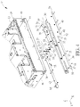
- a casing module 10 includes a casing 12 and a tray mechanism 14.
- the casing 12 includes a first side plate 16 and a second side plate 18 opposite to the first side plate 16.
- the first side plate 16 has a first holding sheet 20 and a second block 22, and the second side plate 18 has a first block 24 and a second holding sheet 26.
- the first holding sheet 20 and the second holding sheet 26 may be bent from the first side plate 16 and the second side plate 18 for holding the tray mechanism 14, but the present disclosure is not limited thereto.
- the tray mechanism 14 includes a tray 28, a fixing plate 30, a sheet 32, a pin 34, a first lock rod 36, a first push rod 38, a second lock rod 40, and a second push rod 42.
- the tray 28 has a bottom plate 44, a third side plate 46, and a fourth side plate 48.
- the third side plate 46 and the fourth side plate 48 are disposed at two sides of the bottom plate 44 respectively for accommodating at least one electronic device 11 (for example, the electronic devices may be display card modules, and, as shown in FIG. 1 , two electronic devices are accommodated, but the present disclosure is not limited thereto) cooperatively with the bottom plate 44.
- the fixing plate 30 is disposed on the bottom plate 44 (e.g. by rivets).
- the sheet 32 is slidably disposed on the fixing plate 30, and the pin 34 is disposed on the sheet 32 (e.g. by inserting the pin 34 into the sheet 32 or by an integral forming process).
- the sheet 32 could have at least one sliding slot 33 (for example, the sheet 32 may include two sliding slots 33 as shown in FIG. 4 , but the present disclosure is not limited thereto), and the fixing plate 30 could have a sliding structure 31 corresponding to the sliding slot 33.
- the sliding structure 31 may be a T-shaped rivet pillar slidably disposed through the sliding slot 31 (but the present disclosure is not limited thereto, that is, the present disclosure could adopt other sliding design, such as the sliding design that the sliding structure could be a sliding block disposed through the sliding slot), such that the sheet 32 may slide upward and downward relative to the fixing plate 30.
- the pin 34 disposed on the sheet 32 may move between a lock position and a release position along a "Z" direction, as shown in FIG. 4 , relative to the fixing plate 30.
- the first lock rod 36 is disposed on the fixing plate 30 in an obliquely slidable manner and has a first abutting end 50 and a first slot end 52.
- the first push rod 38 is disposed on the fixing plate 30 in a transversely slidable manner and has a first hook end 55 and a first protruding-block end 56.
- the second lock rod 40 is disposed on the fixing plate 30 in an obliquely slidable manner and has a second abutting end 58 and a second slot end 60.
- the second push rod 42 is disposed on the fixing plate 30 in a transversely slidable manner and has a second hook end 62 and a second protruding-block end 64.
- a first inclined-surface structure 53 and a first hook 54 are formed on the first hook end 55, and a second inclined-surface structure 61 and a second hook 63 are formed on the second hook end 62.
- the first abutting end 50 and the second protruding-block end 64 protrude from the third side plate 46 respectively, and the second abutting end 58 and the first protruding-block end 56 protrude from the fourth side plate 48 respectively.
- the pin 34 is disposed through the first slot end 52 and the second slot end 60 respectively, and the first hook 54 and the second hook 63 extend from the first inclined-surface structure 53 and the second inclined-surface structure 61 respectively. In such a manner, the first hook 54 and the second hook 63 can releasably hook the pin 34 for constraining movement of the pin 34 in the XYZ directions as shown in FIG. 2 .
- the present disclosure may adopt the pillar-to-slot sliding design to slidably dispose the first lock rod 36, the first push rod 38, the second lock rod 40, and the second push rod 42 on the fixing plate 30.
- the present disclosure is not limited thereto, that is, the present disclosure could adopt other sliding design in another embodiment, such as the block-to-slot sliding design.
- the tray mechanism 14 may include at least one T-shaped pillar 35 (for example, as shown in FIG. 4 , the tray mechanism 14 may utilize three T-shaped pillars 35, but the present disclosure is not limited thereto) disposed through a corresponding oblique slot 37 on the first lock rod 36 and fixed to the fixing plate 30 (e.g.
- the first lock rod 36 can slide obliquely on the fixing plate 30, such that the first abutting end 50 may protrude from the third side plate 46 or retract inwardly relative to the third side plate 46.
- the aforesaid sliding design could be also applied to the first push rod 38, the second lock rod 40, and the second push rod 42, such that the first push rod 38 and the second push rod 42 may slide transversely relative to the fixing plate 30 and the second lock rod 40 may slide obliquely relative to the fixing plate 30.
- the related description could be reasoned by analogy according to the aforesaid description and omitted herein.
- the present disclosure could adopt the surface-to-surface sliding design.
- the first block 24 could have a first oblique surface 66, a first vertical surface 67, and a third oblique surface 68
- the first protruding-block end 56 could have a second oblique surface 69, a second vertical surface 70, and a fourth oblique surface 71 respectively corresponding to the first oblique surface 66, the first vertical surface 67, and the third oblique surface 68.
- the first vertical surface 67 extends from the first oblique surface 66 downward to the third oblique surface 68.
- the second vertical surface 70 extends from the second oblique surface 69 upward to the fourth oblique surface 71.
- the first protruding-block end 56 could be biased smoothly by the first block 24 to retract the first push rod 38 inwardly relative to the fourth side plate 48, or the first protruding-block end 56 could be misaligned with the first block 24 to protrude the first push rod 38 from the fourth side plate 48 during the assembly process of the casing module 10.
- the present disclosure could only adopt the surface-to-surface sliding design of the first oblique surface 66 and the second oblique surface 69, or could only adopt the surface-to-surface sliding design of the first oblique surface 66 and the second oblique surface 69 and the surface-to-surface sliding design of the first vertical surface 67 and the second vertical surface 70, such that the first protruding-block end 56 can be only biased by the first block 24 without being released during the assembly process of the casing module 10 so as to simplify the mechanical design of the present disclosure.
- the first push rod 38 and the second push rod 42 could be moved back to their original positions automatically.
- the present disclosure is not limited thereto, that is, the pin 34, the first push rod 38, and the second push rod 42 could be pushed back to their original positions manually in another embodiment (e.g. pushing the first push rod 38 to its original position via a push button formed thereon).
- the tray mechanism 14 could further include a first spring 72 and second springs 74 and 75.
- the first spring 72 is connected to the sheet 32 and the fixing plate 30.
- the first spring 72 is configured to drive the pin 34 and the sheet 32 back to the lock position.
- the second spring 74 is connected to the first push rod 38 and the fixing plate 30.
- the second spring 74 is configured to drive the first push rod 38 back to its original position, and the first protruding-block end 56 may protrude from the fourth side plate 48.
- the second spring 75 is connected to the second push rod 42 and the fixing plate 30.
- the second spring 75 is configured to drive the second push rod 42 back to its original position, and the second protruding-block end 64 may protrude from the third side plate 46.
- the first side plate 16 could further have a positioning rail 76, and a positioning block 78 could be formed on the third side plate 46 corresponding to the positioning rail 76.
- the second side plate 18 could further have a positioning rail 80, and a positioning block 82 could be formed on the fourth side plate 48 corresponding to the positioning rail 80. Accordingly, during the process of assembling the tray 28 with the casing 12, the positioning block 78 slides along the positioning rail 76 to abut against a bottom of the positioning rail 76 and the positioning block 82 slides along the positioning rail 80 to abut against a bottom of the positioning rail 80, so as to guide the tray 28 to be positioned in the casing 12 precisely.
- the tray mechanism 14 could further include at least one handle 13(for example, as shown in FIG. 2 , the tray mechanism 14 may further include one handle 13, but the present disclosure is not limited thereto).
- the handle 13 is pivoted to the third side plate 46 and the fourth side plate 48 of the tray 28 respectively. As such, the user may lift the tray mechanism 14 steadily by holding the handle 13, and the subsequent assembly operation between the tray mechanism 14 and the casing 12 may be performed.
- FIG. 2 and FIGS. 7-13 More detailed description for the assembly process of the casing module 10 is provided as follows. Please refer to FIG. 2 and FIGS. 7-13 .
- the user when the user wants to perform the assembly operation of the casing module 10, the user just needs to hold the handle 13 and lift the tray mechanism 14 having the electronic device 11 disposed thereon to be located above the casing 12 (as shown in FIG. 2 , the first hook 54 and the second hook 63 hook the pin 34 cooperatively at the lock position), and then abuts the first abutting end 50 protruding from the third side plate 46 against the first holding sheet 20 on the first side plate 16 (the tray mechanism 14 is tilted toward the first side plate 16 relative to the casing 12 as shown in FIG. 7 ).
- the second protruding-block end 64 is biased by the second block 22, and the second push rod 42 may retract inwardly relative to the third side plate 46. Accordingly, the second hook 63 is separate from the pin 34, the first abutting end 50 abuts against the first holding sheet 20 steadily, and the first hook 54 still hooks the pin 34. As such, the first abutting end 50 is unable to retract inwardly.
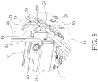
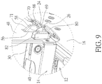
- the user could adjust the tray mechanism 14 from a tilted state as shown in FIG. 7 to a horizontal state relative to the casing 12 as shown in FIG. 8 for abutting the second abutting end 58 protruding from the fourth side plate 48 against the second holding sheet 26 of the second side plate 18 (as shown in FIG. 9 ).
- the first protruding-block end 56 is biased by the first block 24 to retract inwardly relative to the fourth side plate 48, and the first hook 54 may be separated from the pin 34.
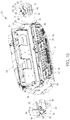
- the first protruding-block end 56 can be further biased by the first block 24 (via surface-to-surface sliding between the first vertical surface 67 and the second vertical surface 70 as shown in FIG. 11 ) and the second protruding-block end 64 can be further biased by the second block 22 (as shown in FIG. 10 ), so as to retract the first push rod 38 inwardly relative to the fourth side plate 48 and to retract the second push rod 42 inwardly relative to the third side plate 46.
- the pin 34 can be pushed by the first inclined-surface structure 53 and the second inclined-surface structure 61 from a position as shown in FIG. 8 upward to the release position as shown in FIG. 10 .
- the pin 34 can drive the first lock rod 36 and the second lock rod 40 to retract inwardly relative to the third side plate 46 and the fourth side plate 48, so as to separate the first abutting end 50 and the second abutting end 58 from the first holding sheet 20 and the second holding sheet 26 respectively.
- the user can mount the tray mechanism 14, as shown in FIG.
- the first protruding-block end 56 and the second protruding-block end 64 can be misaligned with the first block 24 and the second block 22 respectively, so that the pin 34 can move back to the lock position automatically, and the first abutting end 50 and the second abutting end 58 can protrude from the third side plate 46 and the fourth side plate 48.
- the user wants to detach the tray mechanism 14 from the casing 12, the user just needs to hold the handle 13 to lift the tray mechanism 14 to a position, as shown in FIG. 2 , where the tray mechanism 14 is completely separate from the casing 12, so as to complete the disassembly process of the casing module 10.
- the first protruding-block end 56 and the second protruding-block end 64 can be biased by the first block 24 and the second block 22 to prevent the tray mechanism 14 from being interfered with the casing 12. Accordingly, the user can detach the tray mechanism 14 from the casing 12 quickly and smoothly without utilizing any auxiliary tool (e.g. a screw driver) and then subsequent replacement or maintenance operation of the electronic device 11 may be performed.
- any auxiliary tool e.g. a screw driver
- the linkage design including the sheet 32, the pin 34, the first lock rod 36, the first push rod 38, the second lock rod 40, and the second push rod 42 configured on the fixing plate 30 can efficiently improve operational flexibility of the tray mechanism 14. That is to say, the operation of abutting the tray mechanism 14 against the casing 12 is not limited to the aforesaid operation of abutting the first abutting end 50 protruding from the third side plate 46 against the first holding sheet 20 of the first side plate 16 (wherein the tray mechanism 14 is tilted toward the first side plate 16 relative to the casing as shown in FIG. 7 ).
- the second abutting end 58 protruding from the forth side plate 48 may abut against the second holding sheet 26 of the second side plate 18, and the tray mechanism 14 may be adjusted, so as to abut the first abutting end 50 protruding from the third side plate 46 against the first holding sheet 20 of the first side plate 16.
- the tray mechanism 14 may be adjusted, so as to abut the first abutting end 50 protruding from the third side plate 46 against the first holding sheet 20 of the first side plate 16.
- the present disclosure ensures that the tray mechanism can be mounted into the casing from up to down in parallel to the casing.
- the user can mount the tray mechanism into the casing quickly and conveniently without utilizing any auxiliary tool (e.g. a screw driver) and without repeatedly adjusting the mounting position of the tray mechanism relative to the casing.
- any auxiliary tool e.g. a screw driver
- the second push rod and the second lock rod are omissible components for simplifying the mechanical design of the tray mechanism provided by the present disclosure.
- the present disclosure only utilizes linkage among the first push rod, the first lock rod, and the pin to complete the assembly process of the casing module, and the related description could be reasoned by analogy according to the aforesaid embodiments.
- the user assuming that the user abuts the first abutting end of the first lock rod against the first holding sheet of the first side plate first, the user just needs to adjust the tray mechanism to make the first protruding-block end of the first push rod biased by the first block of the second side plate for releasing engagement between the first push rod and the pin. Accordingly, the user can continue mounting the tray mechanism into the casing smoothly to complete the assembly process of the casing module.
Landscapes
- Engineering & Computer Science (AREA)
- Microelectronics & Electronic Packaging (AREA)
- Computer Hardware Design (AREA)
- General Engineering & Computer Science (AREA)
- Casings For Electric Apparatus (AREA)
- Packaging Frangible Articles (AREA)
- Automatic Assembly (AREA)
- Telephone Set Structure (AREA)
Claims (15)
- Fachmechanismus (14) zum Aufnehmen mindestens eines elektronischen Gerätes (11), worin das mindestens eine elektronische Gerät (11) über den Fachmechanismus (14) in einem Gehäuse (12) angebracht ist, das Gehäuse (12) eine erste Seitenplatte (16) und eine zweite Seitenplatte (18) gegenüber der ersten Seitenplatte (16) umfasst, die erste Seitenplatte (16) eine erste Halteplatte (20) aufweist und die zweite Seitenplatte (18) einen ersten Block (24) aufweist, wobei der Fachmechanismus (14) umfasst:ein Fach (28) mit einer Bodenplatte (44), einer dritten Seitenplatte (46) und einer vierten Seitenplatte (48), worin die dritte Seitenplatte (46) und die vierte Seitenplatte (48) an zwei Seiten der Bodenplatte (44) entsprechend angeordnet sind, um zusammen mit der Bodenplatte (44) das mindestens eine elektronische Gerät (11) aufzunehmen;gekennzeichnet durch:eine Befestigungsplatte (30), die auf der Bodenplatte (44) angeordnet ist;eine Platte (32), die verschiebbar auf der Befestigungsplatte (30) angeordnet ist;einen Stift (34), der auf der Platte (32) angeordnet ist, worin der Stift (34) ausgestaltet ist, relativ zur Befestigungsplatte (30) zwischen einer Verriegelungsposition und einer Freigabeposition nach oben und nach unten bewegbar zu sein;eine erste Verriegelungsstange (36), die an der Befestigungsplatte (30) schräg verschiebbar angeordnet ist, worin die erste Verriegelungsstange (36) ein erstes Anschlagende (50), das ausgestaltet ist, an der ersten Halteplatte (20) anzuliegen, und ein erstes Schlitzende (52) aufweist, worin das erste Anschlagende (50) von der dritten Seitenplatte (46) hervorsteht und der Stift (34) durch das erste Schlitzende (52) hindurch angeordnet ist; undeine erste Schubstange (38), die auf der Befestigungsplatte (30) quer verschiebbar angeordnet ist, worin die erste Schubstange (38) ein erstes Hakenende (55) und ein erstes hervorstehendes Blockende (56) aufweist, das ausgestaltet ist, durch den ersten Block (24) vorspannbar zu sein, eine erste Schrägflächenstruktur (53) und ein erster Haken (54) an dem ersten Hakenende (55) ausgebildet sind, der erste Haken (54) sich von der ersten Schrägflächenstruktur (53) erstreckt, um den Stift (34) lösbar einzuhaken, und das erste hervorstehende Blockende (56) von der vierten Seitenplatte (48) hervorsteht;wobei, wenn der erste Block (24) das erste hervorstehende Blockende (56) vorspannt, um die erste Schubstange (38) relativ zu der vierten Seitenplatte (48) nach innen zurückzuziehen, um den ersten Haken (54) von dem Stift (34) zu trennen, die erste Schrägflächenstruktur (53) den Stift (34) nach oben in die Freigabeposition drückt, um die erste Verriegelungsstange (36) anzutreiben, schräg über das erste Schlitzende (52) zu gleiten, um das erste Anschlagende (50) relativ zur dritten Seitenplatte (46) nach innen zurückzuziehen, um von der ersten Haltefolie (20) getrennt zu werden.
- Fachmechanismus (14) nach Anspruch 1, dadurch gekennzeichnet, dass die erste Seitenplatte (16) einen zweiten Block (22) aufweist, die zweite Seitenplatte (18) ferner eine zweite Halteplatte (26) aufweist und der Fachmechanismus (14) ferner umfasst:eine zweite Verriegelungsstange (40), die auf der Befestigungsplatte (30) schräg verschiebbar angeordnet ist, wobei die zweite Verriegelungsstange (40) ein zweites Anschlagende (58) und ein zweites Schlitzende (60) aufweist, das zweite Anschlagende (58) von der vierten Seitenplatte (48) hervorsteht und der Stift (34) durch das zweite Schlitzende (60) hindurch angeordnet ist; undeine zweite Schubstange (42), die auf der Befestigungsplatte (30) in einer quer verschiebbaren Weise angeordnet ist, wobei die zweite Schubstange (42) ein zweites Hakenende (62) und ein zweites hervorstehendes Blockende (64) aufweist, wobei eine zweite Schrägflächenstruktur (61) und ein zweiter Haken (63) an dem zweiten Hakenende (62) ausgebildet sind, der zweite Haken (63) sich von der zweiten Schrägflächenstruktur (61) erstreckt, um den Stift (34) lösbar einzuhaken, und das zweite hervorstehende Blockende (64) von der dritten Seitenplatte (46) hervorsteht;wobei der erste und der zweite Haken (54, 63) von dem Stift (34) getrennt sind, wenn das erste und das zweite Anschlagende (50, 58) an der ersten bzw. der zweiten Halteplatte (20, 26) anliegen und der erste und der zweite Block (24, 22) das erste bzw. das zweite hervorstehende Blockende (56, 64) vorspannen, die erste und die zweite Schrägflächenstruktur (53, 61) den Stift (34) nach oben in die Freigabeposition drücken, um die erste und die zweite Verriegelungsstange (36, 40) anzutreiben, schräg zu gleiten, und das erste und das zweite Anschlagende (50, 58) sich nach innen zurückziehen, um von der ersten und der zweiten Halteplatte (20, 26) getrennt zu sein.
- Fachmechanismus (14) nach Anspruch 1, dadurch gekennzeichnet, dass der erste Block (24) eine erste schräge Fläche (66) aufweist, eine zweite schräge Fläche (69) an dem ersten hervorstehenden Blockende (56) ausgebildet ist, die der ersten schrägen Fläche (66) entspricht, und wenn der erste Block (24) das erste hervorstehende Blockende (56) vorspannt, das erste hervorstehende Blockende (56) entlang der ersten schrägen Oberfläche (66) über die zweite schräge Oberfläche (69) gleitet, und die erste Schubstange (38) sich relativ zu der vierten Seitenplatte (48) nach innen zurückzieht.
- Fachmechanismus (14) nach Anspruch 3, dadurch gekennzeichnet, dass der erste Block (24) ferner eine erste vertikale Fläche (67) aufweist, die sich von der ersten schrägen Fläche (66) nach unten erstreckt, dass eine zweite vertikale Fläche (70) an dem ersten hervorstehenden Blockende (56) ausgebildet ist, die der ersten vertikalen Fläche (67) entspricht, und dadurch dass, wenn das erste hervorstehende Blockende (56) relativ zu der vierten Seitenplatte (48) nach innen zurückgezogen wird und die erste vertikale Fläche (67) an der zweiten vertikalen Fläche (70) anliegt, die erste Schrägflächenstruktur (53) den Stift (34) in die Freigabeposition drückt.
- Fachmechanismus (14) nach Anspruch 4, dadurch gekennzeichnet, dass der erste Block (24) ferner eine dritte schräge Oberfläche (68) aufweist, die sich von der ersten vertikalen Oberfläche (67) nach unten erstreckt, eine vierte schräge Oberfläche (71) an dem ersten hervorstehenden Blockende (56) ausgebildet ist, die der dritten schrägen Oberfläche (68) entspricht, und dadurch dass, wenn das erste hervorstehende Blockende (56) entlang der dritten schrägen Oberfläche (68) über die vierte schräge Oberfläche (71) gleitet, die erste Schubstange (38) aus der vierten Seitenplatte (48) herausragt.
- Fachmechanismus (14) nach Anspruch 1, dadurch gekennzeichnet, dass der Fachmechanismus (14) ferner umfasst:
eine erste Feder (72), die mit der Platte (32) und der Befestigungsplatte (30) verbunden ist, um die Platte (32) anzutreiben und den Stift (34) in die Verriegelungsposition zu bewegen. - Fachmechanismus (14) nach Anspruch 6, dadurch gekennzeichnet, dass der Fachmechanismus (14) ferner umfasst:
eine zweite Feder (74), die mit der ersten Schubstange (38) und der Befestigungsplatte (30) verbunden ist, um die erste Schubstange (38) in ihre ursprüngliche Position zurückzubewegen, damit das erste hervorstehende Blockende (56) von der vierten Seitenplatte (48) hervorsteht. - Fachmechanismus (14) nach Anspruch 1, dadurch gekennzeichnet, dass die erste Seitenplatte (16) ferner eine Anordnungsschiene (76) aufweist, dass ein Anordnungsblock (78) an der dritten Seitenplatte (46) entsprechend der Anordnungsschiene (76) ausgebildet ist, und dadurch dass, wenn das erste Anschlagende (50) sich nach innen zurückzieht und von der ersten Halteplatte (20) getrennt ist, das Fach (28) sich nach unten in das Gehäuse (12) bewegt, und der Anordnungsblock (78) entlang der Anordnungsschiene (76) gleitet, um auf einem Boden der Anordnungsschiene (76) anzuliegen, um das Fach (28) in dem Gehäuse (12) anzuordnen.
- Gehäusemodul (10) zur Aufnahme mindestens eines elektronischen Geräts (11), worin das Gehäusemodul (10) umfasst:ein Gehäuse (12) mit einer ersten Seitenplatte (16) und einer zweiten Seitenplatte (18), die der ersten Seitenplatte (16) gegenüberliegt, wobei die erste Seitenplatte (16) eine erste Halteplatte (20) aufweist und die zweite Seitenplatte (18) einen ersten Block (24) aufweist; undeinen Fachmechanismus (14), der umfasst:ein Fach (28) mit einer Bodenplatte (44), einer dritten Seitenplatte (46) und einer vierten Seitenplatte (48), wobei die dritte Seitenplatte (46) und die vierte Seitenplatte (48) jeweils an zwei Seiten der Bodenplatte (44) angeordnet sind, um die mindestens eine elektronische Gerät (11) zusammenwirkend mit der Bodenplatte (44) aufzunehmengekennzeichnet durch:eine Befestigungsplatte (30), die auf der Bodenplatte (44) angeordnet ist;eine Platte (32), die verschiebbar auf der Befestigungsplatte (30) angeordnet ist;einen Stift (34), der auf der Platte (32) angeordnet ist, worin der Stift (34) ausgestaltet ist, zwischen einer Verriegelungsposition und einer Freigabeposition relativ zur Befestigungsplatte (30) nach oben und nach unten bewegbar zu sein;eine erste Verriegelungsstange (36), die an der Befestigungsplatte (30) schräg verschiebbar angeordnet ist, worin die erste Verriegelungsstange (36) ein erstes Anschlagende (50), das ausgestaltet ist, an der ersten Halteplatte (20) anzuliegen, und ein erstes Schlitzende (52) aufweist, worin das erste Anschlagende (50) von der dritten Seitenplatte (46) hervorsteht und der Stift (34) durch das erste Schlitzende (52) hindurch angeordnet ist; undeine erste Schubstange (38), die auf der Befestigungsplatte (30) quer verschiebbar angeordnet ist, worin die erste Schubstange (38) ein erstes Hakenende (55) und ein erstes hervorstehendes Blockende (56) aufweist, das ausgestaltet ist, durch den ersten Block (24) vorgespannt zu werden, eine erste Schrägflächenstruktur (53) und ein erster Haken (54) an dem ersten Hakenende (55) ausgebildet sind, der erste Haken (54) sich von der ersten Schrägflächenstruktur (53) erstreckt, um den Stift (34) lösbar einzuhaken, und das erste hervorstehende Blockende (56) von der vierten Seitenplatte (48) hervorsteht;wobei, wenn der erste Block (24) das erste hervorstehende Blockende (56) vorspannt, um die erste Schubstange (38) relativ zu der vierten Seitenplatte (48) nach innen zurückzuziehen, um den ersten Haken (54) von dem Stift (34) zu trennen, die erste Schrägflächenstruktur (53) den Stift (34) nach oben in die Freigabeposition drückt, um die erste Verriegelungsstange (36) anzutreiben, schräg über das erste Schlitzende (52) zu gleiten, um das erste Anschlagende (50) relativ zur dritten Seitenplatte (46) nach innen zurückzuziehen, um von der ersten Halteplatte (20) getrennt zu werden.
- Gehäusemodul (10) nach Anspruch 9, dadurch gekennzeichnet, dass die erste Seitenplatte (16) einen zweiten Block (22) aufweist, die zweite Seitenplatte (18) ferner ein zweites Halteblech (26) aufweist und der Fachmechanismus (14) ferner umfasst:eine zweite Verriegelungsstange (40), die auf der Befestigungsplatte (30) schräg verschiebbar angeordnet ist, worin die zweite Verriegelungsstange (40) ein zweites Anschlagende (58) und ein zweites Schlitzende (60) aufweist, das zweite Anschlagende (58) von der vierten Seitenplatte (48) hervorsteht und der Stift (34) durch das zweite Schlitzende (60) hindurch angeordnet ist; undeine zweite Schubstange (42), die auf der Befestigungsplatte (30) in einer quer verschiebbaren Weise angeordnet ist, worin die zweite Schubstange (42) ein zweites Hakenende (62) und ein zweites hervorstehendes Blockende (64) aufweist, worin eine zweite Schrägflächenstruktur (61) und ein zweiter Haken (63) an dem zweiten Hakenende (62) ausgebildet sind, der zweite Haken (63) sich von der zweiten Schrägflächenstruktur (61) erstreckt, um den Stift (34) lösbar einzuhaken, und das zweite hervorstehende Blockende (64) von der dritten Seitenplatte (46) hervorsteht;wobei der erste und der zweite Haken (54, 63) von dem Stift (34) getrennt sind, wenn das erste und das zweite Anschlagende (50, 58) an der ersten bzw. der zweiten Halteplatte (20, 26) anliegen und der erste und der zweite Block (24, 22) das erste bzw. das zweite hervorstehende Blockende (56, 64) vorspannen, die erste und die zweite Schrägflächenstruktur (53, 61) den Stift (34) nach oben in die Freigabeposition drücken, um die erste und die zweite Verriegelungsstange (36, 40) anzutreiben, schräg zu gleiten, und das erste und das zweite Anschlagende (50, 58) sich nach innen zurückziehen, um von der ersten und der zweiten Halteplatte (20, 26) getrennt zu sein.
- Gehäusemodul (10) nach Anspruch 9, dadurch gekennzeichnet, dass der erste Block (24) eine erste schräge Fläche (66) aufweist, an dem ersten hervorstehenden Blockende (56) eine zweite schräge Fläche (69) ausgebildet ist, die der ersten schrägen Fläche (66) entspricht, und wenn der erste Block (24) das erste hervorstehende Blockende (56) vorspannt, das erste hervorstehende Blockende (56) entlang der ersten schrägen Oberfläche (56) über die zweite schräge Oberfläche (69) gleitet, und die erste Schubstange (38) sich relativ zu der vierten Seitenplatte (48) nach innen zurückzieht.
- Gehäusemodul (10) nach Anspruch 11, dadurch gekennzeichnet, dass der erste Block (24) ferner eine erste vertikale Fläche (67) aufweist, die sich von der ersten schrägen Fläche (66) nach unten erstreckt, eine zweite vertikale Fläche (70) an dem ersten hervorstehenden Blockende (56) ausgebildet ist, die der ersten vertikalen Fläche (67) entspricht, und dadurch dass, wenn das erste hervorstehende Blockende (56) relativ zu der vierten Seitenplatte (48) nach innen zurückgezogen wird und die erste vertikale Fläche (67) an der zweiten vertikalen Fläche (70) anliegt, die erste Schrägflächenstruktur (53) den Stift (34) in die Freigabeposition drückt.
- Gehäusemodul (10) nach Anspruch 12, dadurch gekennzeichnet, dass der erste Block (24) ferner eine dritte schräge Oberfläche (68) aufweist, die sich von der ersten vertikalen Oberfläche (67) nach unten erstreckt, eine vierte schräge Oberfläche (71) an dem ersten hervorstehenden Blockende (56) ausgebildet ist, die der dritten schrägen Oberfläche (68) entspricht, und dadurch dass, wenn das erste hervorstehende Blockende (56) entlang der dritten schrägen Oberfläche (68) über die vierte schräge Oberfläche (71) gleitet, die erste Schubstange (38) aus der vierten Seitenplatte (48) hervorsteht.
- Gehäusemodul (10) nach Anspruch 9, dadurch gekennzeichnet, dass der Fachmechanismus (14) ferner umfasst:
eine erste Feder (72), die mit der Platte (32) und der Befestigungsplatte (30) verbunden ist, um die Platte (32) anzutreiben und den Stift (34) in die Verriegelungsposition zu bewegen. - Gehäusemodul (10) nach Anspruch 14, dadurch gekennzeichnet, dass der Fachmechanismus (10) ferner umfasst:
eine zweite Feder (74), die mit der ersten Schubstange (38) und der Befestigungsplatte (30) verbunden ist, um die erste Schubstange (38) in ihre ursprüngliche Position zurückzubewegen, damit das erste hervorstehende Blockende (56) von der vierten Seitenplatte (48) hervorsteht.
Applications Claiming Priority (1)
| Application Number | Priority Date | Filing Date | Title |
|---|---|---|---|
| CN201810338761.6A CN110392504B (zh) | 2018-04-16 | 2018-04-16 | 托盘机构及其机壳模块 |
Publications (2)
| Publication Number | Publication Date |
|---|---|
| EP3557960A1 EP3557960A1 (de) | 2019-10-23 |
| EP3557960B1 true EP3557960B1 (de) | 2021-11-24 |
Family
ID=63363857
Family Applications (1)
| Application Number | Title | Priority Date | Filing Date |
|---|---|---|---|
| EP18188204.4A Active EP3557960B1 (de) | 2018-04-16 | 2018-08-09 | Tablettmechanismus und gehäusemodul dafür |
Country Status (4)
| Country | Link |
|---|---|
| US (1) | US10285300B1 (de) |
| EP (1) | EP3557960B1 (de) |
| CN (1) | CN110392504B (de) |
| TW (1) | TWI652974B (de) |
Families Citing this family (4)
| Publication number | Priority date | Publication date | Assignee | Title |
|---|---|---|---|---|
| CN115391267B (zh) * | 2021-05-24 | 2025-11-04 | 纬联电子科技(中山)有限公司 | 托盘及电子装置 |
| TWI793684B (zh) * | 2021-07-20 | 2023-02-21 | 緯創資通股份有限公司 | 伺服器設備及其托盤機構 |
| CN115696845B (zh) * | 2021-07-30 | 2025-09-30 | 富联精密电子(天津)有限公司 | 风扇固定组件及电子设备 |
| CN116954316A (zh) * | 2022-04-14 | 2023-10-27 | 纬联电子科技(中山)有限公司 | 托盘组件与包含其的电子装置 |
Family Cites Families (23)
| Publication number | Priority date | Publication date | Assignee | Title |
|---|---|---|---|---|
| US5641296A (en) * | 1994-12-23 | 1997-06-24 | Hjs&E Engineering, Inc. | Folding handle carrier assembly |
| US7012808B2 (en) * | 2002-12-20 | 2006-03-14 | Hewlett-Packard Development Company, L.P. | Multi-configurable telecommunications rack mounting system and method incorporating same |
| CN2648774Y (zh) * | 2003-08-15 | 2004-10-13 | 展翊五金电器有限公司 | 电脑机架容置槽的转动结构 |
| JP4105121B2 (ja) * | 2004-05-14 | 2008-06-25 | 富士通株式会社 | 電子機器の筐体構造、及びディスクアレイ装置 |
| WO2006129350A1 (ja) * | 2005-05-31 | 2006-12-07 | Fujitsu Limited | 通信装置、情報処理装置及び外線ケーブルの接続方法 |
| JP4346582B2 (ja) * | 2005-06-24 | 2009-10-21 | 富士通株式会社 | 電子機器、ラックマウント装置、及び、電子機器のラックマウント装置への搭載方法 |
| US7554811B2 (en) * | 2005-12-01 | 2009-06-30 | Xyratex Technology Limited | Data storage device carrier and carrier tray |
| US7771218B2 (en) * | 2008-05-05 | 2010-08-10 | Dell Products L.P. | Electrical coupler mating system |
| US8292382B2 (en) * | 2008-07-08 | 2012-10-23 | Lif J. K. Corporation | Rail set assembly for a machine casing of the industrial computer |
| US8089770B2 (en) * | 2008-08-06 | 2012-01-03 | Oracle America, Inc. | Tool-less multi-stage insertion and securing mechanism for electronic mezzanine assemblies |
| CN101945558B (zh) * | 2009-07-09 | 2012-09-05 | 英业达股份有限公司 | 闩锁机构 |
| CN201804927U (zh) * | 2010-08-12 | 2011-04-20 | 纬创资通股份有限公司 | 固定机构及具有该固定机构的电子装置 |
| US8797764B2 (en) * | 2011-05-06 | 2014-08-05 | International Business Machines Corporation | Adjustable riser cage for varying length adapters |
| CN103068204A (zh) * | 2011-10-24 | 2013-04-24 | 鸿富锦精密工业(深圳)有限公司 | 电子装置 |
| CN102791103B (zh) * | 2012-07-20 | 2015-07-29 | 华为技术有限公司 | 一种插拔机构、包含该插拔机构的插框和成品板 |
| CN104244633A (zh) * | 2013-06-19 | 2014-12-24 | 昆达电脑科技(昆山)有限公司 | 储存装置的控制器壳体 |
| CN203630700U (zh) * | 2013-12-30 | 2014-06-04 | 纬创资通股份有限公司 | 机壳及具有机壳的服务器 |
| JP6424588B2 (ja) * | 2014-11-27 | 2018-11-21 | 富士通株式会社 | ラックマウント装置 |
| US9655269B2 (en) * | 2015-05-12 | 2017-05-16 | Honeywell International Inc. | Support system for printed board assemblies |
| US9590368B2 (en) * | 2015-06-05 | 2017-03-07 | Deere & Company | Chassis for modular electronics assembly |
| CN106550568A (zh) * | 2015-09-18 | 2017-03-29 | 鸿富锦精密工业(武汉)有限公司 | 电子装置壳体 |
| US9706678B1 (en) * | 2016-04-11 | 2017-07-11 | Quanta Computer, Inc. | Configurable server chassis |
| CN107787137B (zh) * | 2016-08-30 | 2020-04-10 | 纬创资通(中山)有限公司 | 电子装置及托盘 |
-
2018
- 2018-04-16 CN CN201810338761.6A patent/CN110392504B/zh active Active
- 2018-05-08 TW TW107115555A patent/TWI652974B/zh active
- 2018-07-04 US US16/027,271 patent/US10285300B1/en active Active
- 2018-08-09 EP EP18188204.4A patent/EP3557960B1/de active Active
Also Published As
| Publication number | Publication date |
|---|---|
| CN110392504A (zh) | 2019-10-29 |
| US10285300B1 (en) | 2019-05-07 |
| TWI652974B (zh) | 2019-03-01 |
| CN110392504B (zh) | 2020-10-09 |
| TW201944871A (zh) | 2019-11-16 |
| EP3557960A1 (de) | 2019-10-23 |
Similar Documents
| Publication | Publication Date | Title |
|---|---|---|
| TWI693877B (zh) | 伺服器設備及其固定機構 | |
| EP3557960A1 (de) | Tablettmechanismus und gehäusemodul dafür | |
| US7510416B2 (en) | PIU plug-in/plug-off mechanism for electronic apparatus | |
| CN113905545B (zh) | 可卸式固定装置及电子装置壳体 | |
| CN110842496B (zh) | 安装装置 | |
| US7272011B2 (en) | Computer enclosure with rotatable cover mounting assembly | |
| CN217689948U (zh) | 安装座与包含其的电子装置 | |
| TW202002746A (zh) | 可拆卸組接裝置 | |
| US8256737B2 (en) | Leverage device and system using same | |
| US20080087050A1 (en) | Lock device for foldable electronic apparatus | |
| US20150137673A1 (en) | Securing mechanism | |
| US8899700B2 (en) | Housing having a carrier device | |
| US11792952B2 (en) | Electronic device and power distribution module | |
| TWI783697B (zh) | 輔助安裝裝置 | |
| TWI859976B (zh) | 機殼組件及電子裝置 | |
| US7254037B2 (en) | Mounting apparatus for motherboards | |
| US20090025434A1 (en) | Buckling assembly and casing structure using the same | |
| CN118034464A (zh) | 壳体组件与包括其的电子装置 | |
| JP2019110246A (ja) | 操作モジュールロック機構 | |
| TWI866593B (zh) | 保持模組及電子裝置 | |
| CN114406659B (zh) | 一种拆卸光器件装置与方法 | |
| CN2919340Y (zh) | 磁碟机锁固装置 | |
| JPH06103881A (ja) | 回路遮断器の電動操作装置 | |
| KR20040026441A (ko) | 통신장비의 피씨비 착탈장치 | |
| TH63416A (th) | กลไกดันคานเส้นลวดสำหรับเครื่องรับส่งทางแสง |
Legal Events
| Date | Code | Title | Description |
|---|---|---|---|
| PUAI | Public reference made under article 153(3) epc to a published international application that has entered the european phase |
Free format text: ORIGINAL CODE: 0009012 |
|
| STAA | Information on the status of an ep patent application or granted ep patent |
Free format text: STATUS: THE APPLICATION HAS BEEN PUBLISHED |
|
| AK | Designated contracting states |
Kind code of ref document: A1 Designated state(s): AL AT BE BG CH CY CZ DE DK EE ES FI FR GB GR HR HU IE IS IT LI LT LU LV MC MK MT NL NO PL PT RO RS SE SI SK SM TR |
|
| AX | Request for extension of the european patent |
Extension state: BA ME |
|
| STAA | Information on the status of an ep patent application or granted ep patent |
Free format text: STATUS: REQUEST FOR EXAMINATION WAS MADE |
|
| 17P | Request for examination filed |
Effective date: 20191022 |
|
| RBV | Designated contracting states (corrected) |
Designated state(s): AL AT BE BG CH CY CZ DE DK EE ES FI FR GB GR HR HU IE IS IT LI LT LU LV MC MK MT NL NO PL PT RO RS SE SI SK SM TR |
|
| GRAP | Despatch of communication of intention to grant a patent |
Free format text: ORIGINAL CODE: EPIDOSNIGR1 |
|
| STAA | Information on the status of an ep patent application or granted ep patent |
Free format text: STATUS: GRANT OF PATENT IS INTENDED |
|
| INTG | Intention to grant announced |
Effective date: 20210705 |
|
| GRAS | Grant fee paid |
Free format text: ORIGINAL CODE: EPIDOSNIGR3 |
|
| GRAA | (expected) grant |
Free format text: ORIGINAL CODE: 0009210 |
|
| STAA | Information on the status of an ep patent application or granted ep patent |
Free format text: STATUS: THE PATENT HAS BEEN GRANTED |
|
| AK | Designated contracting states |
Kind code of ref document: B1 Designated state(s): AL AT BE BG CH CY CZ DE DK EE ES FI FR GB GR HR HU IE IS IT LI LT LU LV MC MK MT NL NO PL PT RO RS SE SI SK SM TR |
|
| REG | Reference to a national code |
Ref country code: GB Ref legal event code: FG4D |
|
| REG | Reference to a national code |
Ref country code: AT Ref legal event code: REF Ref document number: 1450876 Country of ref document: AT Kind code of ref document: T Effective date: 20211215 |
|
| REG | Reference to a national code |
Ref country code: DE Ref legal event code: R096 Ref document number: 602018027053 Country of ref document: DE |
|
| REG | Reference to a national code |
Ref country code: IE Ref legal event code: FG4D |
|
| REG | Reference to a national code |
Ref country code: LT Ref legal event code: MG9D |
|
| REG | Reference to a national code |
Ref country code: NL Ref legal event code: MP Effective date: 20211124 |
|
| REG | Reference to a national code |
Ref country code: AT Ref legal event code: MK05 Ref document number: 1450876 Country of ref document: AT Kind code of ref document: T Effective date: 20211124 |
|
| PG25 | Lapsed in a contracting state [announced via postgrant information from national office to epo] |
Ref country code: RS Free format text: LAPSE BECAUSE OF FAILURE TO SUBMIT A TRANSLATION OF THE DESCRIPTION OR TO PAY THE FEE WITHIN THE PRESCRIBED TIME-LIMIT Effective date: 20211124 Ref country code: LT Free format text: LAPSE BECAUSE OF FAILURE TO SUBMIT A TRANSLATION OF THE DESCRIPTION OR TO PAY THE FEE WITHIN THE PRESCRIBED TIME-LIMIT Effective date: 20211124 Ref country code: FI Free format text: LAPSE BECAUSE OF FAILURE TO SUBMIT A TRANSLATION OF THE DESCRIPTION OR TO PAY THE FEE WITHIN THE PRESCRIBED TIME-LIMIT Effective date: 20211124 Ref country code: BG Free format text: LAPSE BECAUSE OF FAILURE TO SUBMIT A TRANSLATION OF THE DESCRIPTION OR TO PAY THE FEE WITHIN THE PRESCRIBED TIME-LIMIT Effective date: 20220224 Ref country code: AT Free format text: LAPSE BECAUSE OF FAILURE TO SUBMIT A TRANSLATION OF THE DESCRIPTION OR TO PAY THE FEE WITHIN THE PRESCRIBED TIME-LIMIT Effective date: 20211124 |
|
| PG25 | Lapsed in a contracting state [announced via postgrant information from national office to epo] |
Ref country code: IS Free format text: LAPSE BECAUSE OF FAILURE TO SUBMIT A TRANSLATION OF THE DESCRIPTION OR TO PAY THE FEE WITHIN THE PRESCRIBED TIME-LIMIT Effective date: 20220324 Ref country code: SE Free format text: LAPSE BECAUSE OF FAILURE TO SUBMIT A TRANSLATION OF THE DESCRIPTION OR TO PAY THE FEE WITHIN THE PRESCRIBED TIME-LIMIT Effective date: 20211124 Ref country code: PT Free format text: LAPSE BECAUSE OF FAILURE TO SUBMIT A TRANSLATION OF THE DESCRIPTION OR TO PAY THE FEE WITHIN THE PRESCRIBED TIME-LIMIT Effective date: 20220324 Ref country code: PL Free format text: LAPSE BECAUSE OF FAILURE TO SUBMIT A TRANSLATION OF THE DESCRIPTION OR TO PAY THE FEE WITHIN THE PRESCRIBED TIME-LIMIT Effective date: 20211124 Ref country code: NO Free format text: LAPSE BECAUSE OF FAILURE TO SUBMIT A TRANSLATION OF THE DESCRIPTION OR TO PAY THE FEE WITHIN THE PRESCRIBED TIME-LIMIT Effective date: 20220224 Ref country code: NL Free format text: LAPSE BECAUSE OF FAILURE TO SUBMIT A TRANSLATION OF THE DESCRIPTION OR TO PAY THE FEE WITHIN THE PRESCRIBED TIME-LIMIT Effective date: 20211124 Ref country code: LV Free format text: LAPSE BECAUSE OF FAILURE TO SUBMIT A TRANSLATION OF THE DESCRIPTION OR TO PAY THE FEE WITHIN THE PRESCRIBED TIME-LIMIT Effective date: 20211124 Ref country code: HR Free format text: LAPSE BECAUSE OF FAILURE TO SUBMIT A TRANSLATION OF THE DESCRIPTION OR TO PAY THE FEE WITHIN THE PRESCRIBED TIME-LIMIT Effective date: 20211124 Ref country code: GR Free format text: LAPSE BECAUSE OF FAILURE TO SUBMIT A TRANSLATION OF THE DESCRIPTION OR TO PAY THE FEE WITHIN THE PRESCRIBED TIME-LIMIT Effective date: 20220225 Ref country code: ES Free format text: LAPSE BECAUSE OF FAILURE TO SUBMIT A TRANSLATION OF THE DESCRIPTION OR TO PAY THE FEE WITHIN THE PRESCRIBED TIME-LIMIT Effective date: 20211124 |
|
| PG25 | Lapsed in a contracting state [announced via postgrant information from national office to epo] |
Ref country code: SM Free format text: LAPSE BECAUSE OF FAILURE TO SUBMIT A TRANSLATION OF THE DESCRIPTION OR TO PAY THE FEE WITHIN THE PRESCRIBED TIME-LIMIT Effective date: 20211124 Ref country code: SK Free format text: LAPSE BECAUSE OF FAILURE TO SUBMIT A TRANSLATION OF THE DESCRIPTION OR TO PAY THE FEE WITHIN THE PRESCRIBED TIME-LIMIT Effective date: 20211124 Ref country code: RO Free format text: LAPSE BECAUSE OF FAILURE TO SUBMIT A TRANSLATION OF THE DESCRIPTION OR TO PAY THE FEE WITHIN THE PRESCRIBED TIME-LIMIT Effective date: 20211124 Ref country code: EE Free format text: LAPSE BECAUSE OF FAILURE TO SUBMIT A TRANSLATION OF THE DESCRIPTION OR TO PAY THE FEE WITHIN THE PRESCRIBED TIME-LIMIT Effective date: 20211124 Ref country code: DK Free format text: LAPSE BECAUSE OF FAILURE TO SUBMIT A TRANSLATION OF THE DESCRIPTION OR TO PAY THE FEE WITHIN THE PRESCRIBED TIME-LIMIT Effective date: 20211124 Ref country code: CZ Free format text: LAPSE BECAUSE OF FAILURE TO SUBMIT A TRANSLATION OF THE DESCRIPTION OR TO PAY THE FEE WITHIN THE PRESCRIBED TIME-LIMIT Effective date: 20211124 |
|
| REG | Reference to a national code |
Ref country code: DE Ref legal event code: R097 Ref document number: 602018027053 Country of ref document: DE |
|
| PLBE | No opposition filed within time limit |
Free format text: ORIGINAL CODE: 0009261 |
|
| STAA | Information on the status of an ep patent application or granted ep patent |
Free format text: STATUS: NO OPPOSITION FILED WITHIN TIME LIMIT |
|
| PG25 | Lapsed in a contracting state [announced via postgrant information from national office to epo] |
Ref country code: AL Free format text: LAPSE BECAUSE OF FAILURE TO SUBMIT A TRANSLATION OF THE DESCRIPTION OR TO PAY THE FEE WITHIN THE PRESCRIBED TIME-LIMIT Effective date: 20211124 |
|
| 26N | No opposition filed |
Effective date: 20220825 |
|
| PG25 | Lapsed in a contracting state [announced via postgrant information from national office to epo] |
Ref country code: SI Free format text: LAPSE BECAUSE OF FAILURE TO SUBMIT A TRANSLATION OF THE DESCRIPTION OR TO PAY THE FEE WITHIN THE PRESCRIBED TIME-LIMIT Effective date: 20211124 |
|
| PG25 | Lapsed in a contracting state [announced via postgrant information from national office to epo] |
Ref country code: MC Free format text: LAPSE BECAUSE OF FAILURE TO SUBMIT A TRANSLATION OF THE DESCRIPTION OR TO PAY THE FEE WITHIN THE PRESCRIBED TIME-LIMIT Effective date: 20211124 |
|
| REG | Reference to a national code |
Ref country code: CH Ref legal event code: PL |
|
| PG25 | Lapsed in a contracting state [announced via postgrant information from national office to epo] |
Ref country code: LU Free format text: LAPSE BECAUSE OF NON-PAYMENT OF DUE FEES Effective date: 20220809 Ref country code: LI Free format text: LAPSE BECAUSE OF NON-PAYMENT OF DUE FEES Effective date: 20220831 Ref country code: CH Free format text: LAPSE BECAUSE OF NON-PAYMENT OF DUE FEES Effective date: 20220831 |
|
| REG | Reference to a national code |
Ref country code: BE Ref legal event code: MM Effective date: 20220831 |
|
| PG25 | Lapsed in a contracting state [announced via postgrant information from national office to epo] |
Ref country code: IT Free format text: LAPSE BECAUSE OF FAILURE TO SUBMIT A TRANSLATION OF THE DESCRIPTION OR TO PAY THE FEE WITHIN THE PRESCRIBED TIME-LIMIT Effective date: 20211124 |
|
| P01 | Opt-out of the competence of the unified patent court (upc) registered |
Effective date: 20230603 |
|
| PG25 | Lapsed in a contracting state [announced via postgrant information from national office to epo] |
Ref country code: IE Free format text: LAPSE BECAUSE OF NON-PAYMENT OF DUE FEES Effective date: 20220809 |
|
| PG25 | Lapsed in a contracting state [announced via postgrant information from national office to epo] |
Ref country code: BE Free format text: LAPSE BECAUSE OF NON-PAYMENT OF DUE FEES Effective date: 20220831 |
|
| PG25 | Lapsed in a contracting state [announced via postgrant information from national office to epo] |
Ref country code: HU Free format text: LAPSE BECAUSE OF FAILURE TO SUBMIT A TRANSLATION OF THE DESCRIPTION OR TO PAY THE FEE WITHIN THE PRESCRIBED TIME-LIMIT; INVALID AB INITIO Effective date: 20180809 |
|
| PG25 | Lapsed in a contracting state [announced via postgrant information from national office to epo] |
Ref country code: CY Free format text: LAPSE BECAUSE OF FAILURE TO SUBMIT A TRANSLATION OF THE DESCRIPTION OR TO PAY THE FEE WITHIN THE PRESCRIBED TIME-LIMIT Effective date: 20211124 |
|
| PG25 | Lapsed in a contracting state [announced via postgrant information from national office to epo] |
Ref country code: MK Free format text: LAPSE BECAUSE OF FAILURE TO SUBMIT A TRANSLATION OF THE DESCRIPTION OR TO PAY THE FEE WITHIN THE PRESCRIBED TIME-LIMIT Effective date: 20211124 |
|
| REG | Reference to a national code |
Ref country code: DE Ref legal event code: R082 Ref document number: 602018027053 Country of ref document: DE Representative=s name: STRAUS, ALEXANDER, DIPL.-CHEM.UNIV. DR.PHIL., DE |
|
| PG25 | Lapsed in a contracting state [announced via postgrant information from national office to epo] |
Ref country code: MT Free format text: LAPSE BECAUSE OF FAILURE TO SUBMIT A TRANSLATION OF THE DESCRIPTION OR TO PAY THE FEE WITHIN THE PRESCRIBED TIME-LIMIT Effective date: 20211124 |
|
| PGFP | Annual fee paid to national office [announced via postgrant information from national office to epo] |
Ref country code: DE Payment date: 20250717 Year of fee payment: 8 |
|
| PGFP | Annual fee paid to national office [announced via postgrant information from national office to epo] |
Ref country code: GB Payment date: 20250710 Year of fee payment: 8 |
|
| PGFP | Annual fee paid to national office [announced via postgrant information from national office to epo] |
Ref country code: FR Payment date: 20250710 Year of fee payment: 8 |
|
| PG25 | Lapsed in a contracting state [announced via postgrant information from national office to epo] |
Ref country code: TR Free format text: LAPSE BECAUSE OF FAILURE TO SUBMIT A TRANSLATION OF THE DESCRIPTION OR TO PAY THE FEE WITHIN THE PRESCRIBED TIME-LIMIT Effective date: 20211124 |