EP3557673B1 - Elektrochemischer stapel - Google Patents
Elektrochemischer stapel Download PDFInfo
- Publication number
- EP3557673B1 EP3557673B1 EP19177224.3A EP19177224A EP3557673B1 EP 3557673 B1 EP3557673 B1 EP 3557673B1 EP 19177224 A EP19177224 A EP 19177224A EP 3557673 B1 EP3557673 B1 EP 3557673B1
- Authority
- EP
- European Patent Office
- Prior art keywords
- stack
- compression
- compression system
- electrochemical
- gib
- Prior art date
- Legal status (The legal status is an assumption and is not a legal conclusion. Google has not performed a legal analysis and makes no representation as to the accuracy of the status listed.)
- Active
Links
- 230000006835 compression Effects 0.000 claims description 118
- 238000007906 compression Methods 0.000 claims description 118
- 230000007246 mechanism Effects 0.000 claims description 61
- 239000000835 fiber Substances 0.000 claims description 30
- 239000000463 material Substances 0.000 claims description 20
- 238000000034 method Methods 0.000 claims description 6
- 230000008859 change Effects 0.000 claims description 4
- 230000004044 response Effects 0.000 claims description 4
- 229920000049 Carbon (fiber) Polymers 0.000 claims 1
- 239000004917 carbon fiber Substances 0.000 claims 1
- 239000012528 membrane Substances 0.000 description 21
- 239000003792 electrolyte Substances 0.000 description 15
- -1 e.g. Substances 0.000 description 14
- 239000001257 hydrogen Substances 0.000 description 13
- 229910052739 hydrogen Inorganic materials 0.000 description 13
- UFHFLCQGNIYNRP-UHFFFAOYSA-N Hydrogen Chemical compound [H][H] UFHFLCQGNIYNRP-UHFFFAOYSA-N 0.000 description 12
- 239000000446 fuel Substances 0.000 description 11
- QVGXLLKOCUKJST-UHFFFAOYSA-N atomic oxygen Chemical compound [O] QVGXLLKOCUKJST-UHFFFAOYSA-N 0.000 description 7
- 238000000576 coating method Methods 0.000 description 7
- 239000001301 oxygen Substances 0.000 description 7
- 229910052760 oxygen Inorganic materials 0.000 description 7
- XLYOFNOQVPJJNP-UHFFFAOYSA-N water Substances O XLYOFNOQVPJJNP-UHFFFAOYSA-N 0.000 description 7
- 229910001868 water Inorganic materials 0.000 description 7
- 239000011248 coating agent Substances 0.000 description 6
- 239000007789 gas Substances 0.000 description 6
- 229910052751 metal Inorganic materials 0.000 description 6
- 239000002184 metal Substances 0.000 description 6
- 229910052782 aluminium Inorganic materials 0.000 description 5
- XAGFODPZIPBFFR-UHFFFAOYSA-N aluminium Chemical compound [Al] XAGFODPZIPBFFR-UHFFFAOYSA-N 0.000 description 5
- 230000008901 benefit Effects 0.000 description 5
- 239000010935 stainless steel Substances 0.000 description 5
- 229910001220 stainless steel Inorganic materials 0.000 description 5
- OKTJSMMVPCPJKN-UHFFFAOYSA-N Carbon Chemical compound [C] OKTJSMMVPCPJKN-UHFFFAOYSA-N 0.000 description 4
- 239000004677 Nylon Substances 0.000 description 4
- 239000004696 Poly ether ether ketone Substances 0.000 description 4
- 239000004698 Polyethylene Substances 0.000 description 4
- 229910000831 Steel Inorganic materials 0.000 description 4
- 239000003054 catalyst Substances 0.000 description 4
- 238000006243 chemical reaction Methods 0.000 description 4
- 230000005611 electricity Effects 0.000 description 4
- 238000005516 engineering process Methods 0.000 description 4
- 150000002739 metals Chemical class 0.000 description 4
- 229920001778 nylon Polymers 0.000 description 4
- 229920002530 polyetherether ketone Polymers 0.000 description 4
- 229920000573 polyethylene Polymers 0.000 description 4
- 239000010959 steel Substances 0.000 description 4
- OKKJLVBELUTLKV-UHFFFAOYSA-N Methanol Chemical compound OC OKKJLVBELUTLKV-UHFFFAOYSA-N 0.000 description 3
- 239000004642 Polyimide Substances 0.000 description 3
- 229920006362 Teflon® Polymers 0.000 description 3
- RTAQQCXQSZGOHL-UHFFFAOYSA-N Titanium Chemical compound [Ti] RTAQQCXQSZGOHL-UHFFFAOYSA-N 0.000 description 3
- 229910045601 alloy Inorganic materials 0.000 description 3
- 239000000956 alloy Substances 0.000 description 3
- 229910052799 carbon Inorganic materials 0.000 description 3
- 239000000919 ceramic Substances 0.000 description 3
- 230000003247 decreasing effect Effects 0.000 description 3
- 238000003780 insertion Methods 0.000 description 3
- 230000037431 insertion Effects 0.000 description 3
- 229910001092 metal group alloy Inorganic materials 0.000 description 3
- VNWKTOKETHGBQD-UHFFFAOYSA-N methane Chemical compound C VNWKTOKETHGBQD-UHFFFAOYSA-N 0.000 description 3
- 229920001721 polyimide Polymers 0.000 description 3
- 229920000642 polymer Polymers 0.000 description 3
- 229920001343 polytetrafluoroethylene Polymers 0.000 description 3
- 239000004810 polytetrafluoroethylene Substances 0.000 description 3
- 230000009467 reduction Effects 0.000 description 3
- 238000000926 separation method Methods 0.000 description 3
- 229910052719 titanium Inorganic materials 0.000 description 3
- 239000010936 titanium Substances 0.000 description 3
- LYCAIKOWRPUZTN-UHFFFAOYSA-N Ethylene glycol Chemical compound OCCO LYCAIKOWRPUZTN-UHFFFAOYSA-N 0.000 description 2
- XEEYBQQBJWHFJM-UHFFFAOYSA-N Iron Chemical compound [Fe] XEEYBQQBJWHFJM-UHFFFAOYSA-N 0.000 description 2
- PXHVJJICTQNCMI-UHFFFAOYSA-N Nickel Chemical compound [Ni] PXHVJJICTQNCMI-UHFFFAOYSA-N 0.000 description 2
- VYPSYNLAJGMNEJ-UHFFFAOYSA-N Silicium dioxide Chemical compound O=[Si]=O VYPSYNLAJGMNEJ-UHFFFAOYSA-N 0.000 description 2
- 239000004020 conductor Substances 0.000 description 2
- 238000013461 design Methods 0.000 description 2
- 238000009792 diffusion process Methods 0.000 description 2
- 238000005868 electrolysis reaction Methods 0.000 description 2
- 150000002431 hydrogen Chemical class 0.000 description 2
- 238000004519 manufacturing process Methods 0.000 description 2
- 239000011159 matrix material Substances 0.000 description 2
- 239000007800 oxidant agent Substances 0.000 description 2
- BASFCYQUMIYNBI-UHFFFAOYSA-N platinum Chemical compound [Pt] BASFCYQUMIYNBI-UHFFFAOYSA-N 0.000 description 2
- 239000000758 substrate Substances 0.000 description 2
- 229910001018 Cast iron Inorganic materials 0.000 description 1
- RYGMFSIKBFXOCR-UHFFFAOYSA-N Copper Chemical compound [Cu] RYGMFSIKBFXOCR-UHFFFAOYSA-N 0.000 description 1
- 101100437784 Drosophila melanogaster bocks gene Proteins 0.000 description 1
- 239000004593 Epoxy Substances 0.000 description 1
- 229920000271 Kevlar® Polymers 0.000 description 1
- 229920000914 Metallic fiber Polymers 0.000 description 1
- 229910019142 PO4 Inorganic materials 0.000 description 1
- 239000004743 Polypropylene Substances 0.000 description 1
- NRTOMJZYCJJWKI-UHFFFAOYSA-N Titanium nitride Chemical compound [Ti]#N NRTOMJZYCJJWKI-UHFFFAOYSA-N 0.000 description 1
- PNEYBMLMFCGWSK-UHFFFAOYSA-N aluminium oxide Inorganic materials [O-2].[O-2].[O-2].[Al+3].[Al+3] PNEYBMLMFCGWSK-UHFFFAOYSA-N 0.000 description 1
- 239000004760 aramid Substances 0.000 description 1
- 229920003235 aromatic polyamide Polymers 0.000 description 1
- 229910010293 ceramic material Inorganic materials 0.000 description 1
- 239000002131 composite material Substances 0.000 description 1
- 239000012809 cooling fluid Substances 0.000 description 1
- 239000010949 copper Substances 0.000 description 1
- 229910052802 copper Inorganic materials 0.000 description 1
- 238000005260 corrosion Methods 0.000 description 1
- 230000007797 corrosion Effects 0.000 description 1
- 238000005336 cracking Methods 0.000 description 1
- 239000002001 electrolyte material Substances 0.000 description 1
- 239000002657 fibrous material Substances 0.000 description 1
- 239000002803 fossil fuel Substances 0.000 description 1
- 239000003502 gasoline Substances 0.000 description 1
- 239000011521 glass Substances 0.000 description 1
- PCHJSUWPFVWCPO-UHFFFAOYSA-N gold Chemical compound [Au] PCHJSUWPFVWCPO-UHFFFAOYSA-N 0.000 description 1
- 229910052737 gold Inorganic materials 0.000 description 1
- 239000010931 gold Substances 0.000 description 1
- 229910002804 graphite Inorganic materials 0.000 description 1
- 239000010439 graphite Substances 0.000 description 1
- 125000004435 hydrogen atom Chemical group [H]* 0.000 description 1
- WGCNASOHLSPBMP-UHFFFAOYSA-N hydroxyacetaldehyde Natural products OCC=O WGCNASOHLSPBMP-UHFFFAOYSA-N 0.000 description 1
- 229910001026 inconel Inorganic materials 0.000 description 1
- 229910052742 iron Inorganic materials 0.000 description 1
- 239000007788 liquid Substances 0.000 description 1
- 239000000314 lubricant Substances 0.000 description 1
- 238000012423 maintenance Methods 0.000 description 1
- 229910001463 metal phosphate Inorganic materials 0.000 description 1
- 239000000203 mixture Substances 0.000 description 1
- 238000012986 modification Methods 0.000 description 1
- 230000004048 modification Effects 0.000 description 1
- 239000003345 natural gas Substances 0.000 description 1
- 229910052759 nickel Inorganic materials 0.000 description 1
- 230000001590 oxidative effect Effects 0.000 description 1
- 235000021317 phosphate Nutrition 0.000 description 1
- 150000003013 phosphoric acid derivatives Chemical class 0.000 description 1
- 239000004033 plastic Substances 0.000 description 1
- 229920003023 plastic Polymers 0.000 description 1
- 229910052697 platinum Inorganic materials 0.000 description 1
- 229920005597 polymer membrane Polymers 0.000 description 1
- 229920001155 polypropylene Polymers 0.000 description 1
- 239000004800 polyvinyl chloride Substances 0.000 description 1
- 229920000915 polyvinyl chloride Polymers 0.000 description 1
- 239000011148 porous material Substances 0.000 description 1
- 230000036316 preload Effects 0.000 description 1
- 230000008569 process Effects 0.000 description 1
- 239000000376 reactant Substances 0.000 description 1
- 239000000377 silicon dioxide Substances 0.000 description 1
- 239000000126 substance Substances 0.000 description 1
- 238000006467 substitution reaction Methods 0.000 description 1
- 238000013519 translation Methods 0.000 description 1
- 239000002699 waste material Substances 0.000 description 1
- LEHFSLREWWMLPU-UHFFFAOYSA-B zirconium(4+);tetraphosphate Chemical class [Zr+4].[Zr+4].[Zr+4].[O-]P([O-])([O-])=O.[O-]P([O-])([O-])=O.[O-]P([O-])([O-])=O.[O-]P([O-])([O-])=O LEHFSLREWWMLPU-UHFFFAOYSA-B 0.000 description 1
Images

Classifications
-
- H—ELECTRICITY
- H01—ELECTRIC ELEMENTS
- H01M—PROCESSES OR MEANS, e.g. BATTERIES, FOR THE DIRECT CONVERSION OF CHEMICAL ENERGY INTO ELECTRICAL ENERGY
- H01M8/00—Fuel cells; Manufacture thereof
- H01M8/24—Grouping of fuel cells, e.g. stacking of fuel cells
- H01M8/2465—Details of groupings of fuel cells
- H01M8/247—Arrangements for tightening a stack, for accommodation of a stack in a tank or for assembling different tanks
- H01M8/2475—Enclosures, casings or containers of fuel cell stacks
-
- C—CHEMISTRY; METALLURGY
- C25—ELECTROLYTIC OR ELECTROPHORETIC PROCESSES; APPARATUS THEREFOR
- C25B—ELECTROLYTIC OR ELECTROPHORETIC PROCESSES FOR THE PRODUCTION OF COMPOUNDS OR NON-METALS; APPARATUS THEREFOR
- C25B1/00—Electrolytic production of inorganic compounds or non-metals
- C25B1/01—Products
- C25B1/02—Hydrogen or oxygen
- C25B1/04—Hydrogen or oxygen by electrolysis of water
-
- C—CHEMISTRY; METALLURGY
- C25—ELECTROLYTIC OR ELECTROPHORETIC PROCESSES; APPARATUS THEREFOR
- C25B—ELECTROLYTIC OR ELECTROPHORETIC PROCESSES FOR THE PRODUCTION OF COMPOUNDS OR NON-METALS; APPARATUS THEREFOR
- C25B9/00—Cells or assemblies of cells; Constructional parts of cells; Assemblies of constructional parts, e.g. electrode-diaphragm assemblies; Process-related cell features
- C25B9/05—Pressure cells
-
- C—CHEMISTRY; METALLURGY
- C25—ELECTROLYTIC OR ELECTROPHORETIC PROCESSES; APPARATUS THEREFOR
- C25B—ELECTROLYTIC OR ELECTROPHORETIC PROCESSES FOR THE PRODUCTION OF COMPOUNDS OR NON-METALS; APPARATUS THEREFOR
- C25B9/00—Cells or assemblies of cells; Constructional parts of cells; Assemblies of constructional parts, e.g. electrode-diaphragm assemblies; Process-related cell features
- C25B9/70—Assemblies comprising two or more cells
- C25B9/73—Assemblies comprising two or more cells of the filter-press type
- C25B9/77—Assemblies comprising two or more cells of the filter-press type having diaphragms
-
- H—ELECTRICITY
- H01—ELECTRIC ELEMENTS
- H01M—PROCESSES OR MEANS, e.g. BATTERIES, FOR THE DIRECT CONVERSION OF CHEMICAL ENERGY INTO ELECTRICAL ENERGY
- H01M8/00—Fuel cells; Manufacture thereof
- H01M8/24—Grouping of fuel cells, e.g. stacking of fuel cells
- H01M8/2465—Details of groupings of fuel cells
- H01M8/247—Arrangements for tightening a stack, for accommodation of a stack in a tank or for assembling different tanks
- H01M8/248—Means for compression of the fuel cell stacks
-
- Y—GENERAL TAGGING OF NEW TECHNOLOGICAL DEVELOPMENTS; GENERAL TAGGING OF CROSS-SECTIONAL TECHNOLOGIES SPANNING OVER SEVERAL SECTIONS OF THE IPC; TECHNICAL SUBJECTS COVERED BY FORMER USPC CROSS-REFERENCE ART COLLECTIONS [XRACs] AND DIGESTS
- Y02—TECHNOLOGIES OR APPLICATIONS FOR MITIGATION OR ADAPTATION AGAINST CLIMATE CHANGE
- Y02E—REDUCTION OF GREENHOUSE GAS [GHG] EMISSIONS, RELATED TO ENERGY GENERATION, TRANSMISSION OR DISTRIBUTION
- Y02E60/00—Enabling technologies; Technologies with a potential or indirect contribution to GHG emissions mitigation
- Y02E60/30—Hydrogen technology
- Y02E60/36—Hydrogen production from non-carbon containing sources, e.g. by water electrolysis
-
- Y—GENERAL TAGGING OF NEW TECHNOLOGICAL DEVELOPMENTS; GENERAL TAGGING OF CROSS-SECTIONAL TECHNOLOGIES SPANNING OVER SEVERAL SECTIONS OF THE IPC; TECHNICAL SUBJECTS COVERED BY FORMER USPC CROSS-REFERENCE ART COLLECTIONS [XRACs] AND DIGESTS
- Y02—TECHNOLOGIES OR APPLICATIONS FOR MITIGATION OR ADAPTATION AGAINST CLIMATE CHANGE
- Y02E—REDUCTION OF GREENHOUSE GAS [GHG] EMISSIONS, RELATED TO ENERGY GENERATION, TRANSMISSION OR DISTRIBUTION
- Y02E60/00—Enabling technologies; Technologies with a potential or indirect contribution to GHG emissions mitigation
- Y02E60/30—Hydrogen technology
- Y02E60/50—Fuel cells
Definitions
- Embodiments of the present disclosure relate to electrochemical cells, and more particularly, to systems for applying a compressive force to high differential pressure electrochemical cell stacks.
- Electrochemical cells are used to generate an electric current from chemical reactions. Electrochemical cell technology, like fuel cells and hydrogen compressors, offers a promising alternative to traditional power sources, such as fossil fuels, for a range of technologies, including, for example, transportation vehicles, portable power supplies, and stationary power production.
- An electrochemical cell converts the chemical energy of a proton source (e.g., hydrogen, natural gas, methanol, gasoline, etc.) into electricity through a chemical reaction with oxygen or another oxidizing agent. The chemical reaction typically yields electricity, heat, and water.
- a proton source e.g., hydrogen, natural gas, methanol, gasoline, etc.
- a basic high differential pressure electrochemical cell comprises a negatively charged anode, a positively charged cathode, and an ion-conducting material called an electrolyte.
- Different electrochemical cell technologies utilize different electrolyte materials.
- a Proton Exchange Membrane (PEM) cell for example, utilizes a polymeric, ion-conducting membrane as the electrolyte.
- a fuel such as hydrogen gas
- hydrogen may be split into positively charged protons and negatively charged electrons.
- the protons may then pass through an electrolyte membrane, such as a PEM, to a cathode side of the cell.
- the PEM may be configured to allow only the positively charged protons to pass through to the cathode side of the cell.
- the negatively charged electrons may be forced to pass through an external electric load circuit to reach the cathode side of the cell, and in doing so, may generate a usable electrical current.
- Oxygen may be delivered to the cathode side of the cell, where it may react with the protons and the electrons to form water molecules and heat as waste.
- the cathode, electrolyte membrane, and anode of an individual electrochemical cell may collectively form a "membrane electrode assembly" (MEA), which may be supported on both sides by bipolar plates.
- Gases, such as hydrogen and oxygen, may be supplied to the electrodes of the MEA through channels or grooves formed in the bipolar plates.
- a single cell may generally produce a relatively small electrical potential, about 0.2-1 volt, depending on the current.
- individual electrochemical cells may be stacked together, typically in series, to form an electrochemical cell stack. The number of individual cells in a stack may depend on the application and the amount of output required from the stack for that application.
- the electrochemical cell stack may receive flows of hydrogen and oxygen, which may be distributed to the individual cells. Proper operation of the cell stack may require the maintenance of effective seals between the individual cells, components of the cells, and flow conduits. Accordingly, the electrochemical cells in a stack may need to be compressed against one another to maintain sufficient electrical contact between the internal components of each cell. The amount of compression between the cells may affect the contact resistance, electrical conduction, and membrane porosity, and thus may affect the overall performance of the electrochemical cells. Accordingly, in order to maintain contact between the cells and increase performance, uniform compression is typically distributed over the electrochemical cell stack.
- tie rods, bands, and/or springs may be used to apply compressive force to a cell stack.
- These compression mechanisms typically require the use of end plates located at both ends of the electrochemical cell stack.
- end plates may cap each end of a cell stack, and tie rods may extend from one end plate to the other, either external to the stack along the periphery, or within the stack by passing through openings in the cells of the stack.
- the tie rods may be tightened or loosened to move the end plates towards or away from each other to adjust the amount of compression exerted on the stack.
- bands may also be wrapped around the stack, stretching from end plate to end plate, to maintain compression.
- the present disclosure is directed toward the design of improved compression systems for use with electrochemical cells.
- the present disclosure is directed towards the design of adjustable compression structures for use with electrochemical cells.
- Such devices may be used in electrochemical cells operating under high differential pressures, including, but not limited to hydrogen compressors, fuel cells, electrolysis cells, hydrogen purifiers, and hydrogen expanders.
- US5993987 discloses an electrochemical fuel cell stack in which the mechanism for securing the stack in its compressed, assembled state includes at least one compression band which circumscribes the stack in the longitudinal direction.
- US2006093890 discloses a fuel cell stack comprising a pair of end plates, a plurality of fuel cells supported between the end plates and a stack compression system adapted to maintain compression of the fuel cells between the end plates, wherein the stack compression system is free from rigid tie rods that extend between the end plates to apply compression to the fuel cells by drawing the end plates together.
- Embodiments of the present disclosure are directed to a system for applying compressive force to electrochemical cell stacks.
- an electrochemical cell stack compression system may include an integral, hollow frame configured to contain a plurality of electrochemical cells arranged along an axis in a stack configuration, wherein the frame has a defined shape and forms a continuous border around a periphery of the electrochemical cell stack when inserted, and wherein the frame is formed of a plurality of fibers.
- the frame may be formed of a plurality of fibers composed of different materials; the frame may include multiple layers formed of fibers; the frame may include a friction-reducing layer located between at least one of the multiple layers formed of fibers; the frame may include at least two opposing wall surfaces; the frame may be further configured to contain at least one end block located at an end region of the frame; the frame may be further configured to contain at least one compression mechanism configured to apply a compressive force to the electrochemical cell stack; the compression mechanism may include at least one gib; the compression mechanism may be configured to expand when heated; the compression mechanism may include one or more internal drive screws extending between two separate portions, wherein rotating the internal drive screws in one direction moves the two portions further away from each other and rotating the internal drive screws in the opposite direction moves the two portions closer to each other; and the frame may be configured to accommodate multiple different sizes of electrochemical cell stacks.
- an electrochemical stack compression system includes a structure having a defined shape that is configured to receive and contain a plurality of electrochemical cells arranged in a series along an axis to form an electrochemical stack and at least one compression mechanism configured to apply a compressive force to the electrochemical stack located adjacent to and along the axis of the electrochemical stack, wherein the structure forms a continuous border surrounding the electrochemical stack and the at least one compression mechanism when contained.
- the compression mechanism may include at least one gib; the compression mechanism may include a block that is configured to expand in response to an increase in temperature; the compression mechanism may include internal drive screws configured to increase the size of the compression mechanism when the internal drive screws are rotated in a first direction and to decrease the size of the compression mechanism when the internal drive screws are rotated in a second direction opposite the first direction; the structure may be formed of wound fibers; the fibers may be non-conductive; the fibers may be carbon; and a height of the structure along the axis of the electrochemical stack may change in response to a load applied by the compression mechanism to the electrochemical stack when receiving the compression mechanism.
- a method of preloading various embodiments of the disclosure may include inserting the electrochemical stack into the structure, inserting the at least one compression mechanism into the structure, configuring the compression mechanism to apply a predetermined load within the compression system, and measuring a change in height of the structure along the axis of the electrochemical stack to determine the load being applied by the compression mechanism.
- Various embodiments of the method may further include: inserting at least one end block into the structure; the compression mechanism may include two gibs and configuring the compression mechanism may include wedging the two gibs against each other; configuring the compression mechanism may include increasing the temperature of the compression system to expand the compression mechanism; and configuring the compression mechanism includes rotating a plurality of internal drive screws to expand the compression mechanism.
- an electrochemical stack compression system includes an integral, hollow structure having a defined shape and formed of a plurality of wound fibers; a plurality of electrochemical cells arranged in a series along an axis to form an electrochemical stack, wherein the electrochemical stack is contained within the structure; at least one end block contained within the structure and located at an end region of the structure; and at least one compression mechanism contained within the structure, wherein the at least one compression mechanism is configured to apply a compressive force to the electrochemical stack, and wherein the electrochemical stack, the at least one end block, and the at least one compression mechanism are contained in series within the structure such that the structure forms a continuous border around and adjacent to a periphery of the electrochemical stack, the at least one end block, and the at least one compression mechanism.
- the fibers may be configured to stretch and contract in response to changes in the compressive force;
- the at least one compression mechanism may include a gib; and the at least one compression mechanism may be configured to expand.
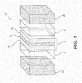
- FIG. 1 depicts an individual electrochemical cell 10, according to an embodiment of the present disclosure.
- cell 10 includes a central, electrolyte membrane 8.
- Electrolyte membrane 8 may be positioned between an anode 7A and a cathode 7B. Together, electrolyte membrane 8, anode 7A, and cathode 7B may form MEA 3.
- Hydrogen atoms supplied to anode 7A may be electrochemically split into electrons and protons. The electrons may flow through an electric circuit (not shown) to cathode 7B, generating electricity in the process, while the protons may pass through electrolyte membrane 8 to cathode 7B.
- protons may react with electrons and oxygen supplied to cathode 7B to produce water and heat.
- Electrolyte membrane 8 may electrically insulate anode 7A from cathode 7B.
- Electrolyte membrane 8 may be any suitable membrane, including, e.g., a PEM membrane.
- Electrolyte membrane 8 may be formed of a pure polymer membrane or a composite membrane, which may include, e.g., silica, heteropolyacids, layered metal phosphates, phosphates, and zirconium phosphates, embedded in a polymer matrix. Electrolyte membrane 8 may be permeable to protons but may not conduct electrons.
- Anode 7A and cathode 7B may include porous carbon electrodes containing a catalyst.
- the catalyst material e.g., platinum or any other suitable material, may speed up the reaction of oxygen and fuel.
- the size and shape of MEA 3 may be increased or decreased depending on the application of cell 10 and the given load requirements.
- the thickness, length, or width of MEA 3 may be adjusted according to the given application and requirements.
- the concentration of catalyst material in anode 7A and cathode 7B may be adjusted according to the given application.
- the concentration of catalyst material in anode 7A and cathode 7B and the thickness of electrolyte membrane 8 may each affect the total thickness of MEA 3.
- electrochemical cell 10 may optionally include one or more electrically conductive flow structures 5 on each side of MEA 3.
- Flow structures 5 may serve as diffusion media enabling the transport of gases and liquids within cell 10.
- Flow structures 5 may also promote electrical conduction, aid in the removal of heat and water from electrochemical cell 10, and provide mechanical support to electrolyte membrane 8.
- Flow structures 5 may include, e.g., flow fields, gas diffusion layers (GDL), or any suitable combination thereof.
- Flow structures 5 may be formed of "frit"-type sintered metals, layered structures, e.g., screen packs and expanded metals, and three-dimensional porous substrates.
- An exemplary porous metallic substrate may consist of two distinct layers having different average pore sizes.
- Such flow structures 5 may be formed of any suitable material, including, e.g., metals or metal alloys, such as, e.g., stainless steel, titanium, aluminum, nickel, iron, and nickel-chrome alloys, or any combination thereof.
- flow structures 5 may include a suitable coating, such as a corrosion-resistant coating, like carbon, gold, or titanium-nitride.
- the reactant gases on each side of the electrolyte membrane are often present at different pressures, e.g., operating pressures may range from approximately 0 psid to 15,000 psid, creating a pressure differential across MEA 3.
- operating pressures may range from approximately 0 psid to 15,000 psid, creating a pressure differential across MEA 3.
- the pressure differential may create a force on MEA 3 that causes MEA 3 to move away from the high pressure side toward the low pressure side. This movement may cause a reduction in contact pressure and separation of the contacting surface of MEA 3 from flow structures 5 on the high-pressure side.
- Reduction in pressure and subsequent separation between the contacting surfaces of MEA 3 and high-pressure flow structures 5 may reduce the electrical conduction and increase the contact resistance between the two, reducing the efficiency of electrochemical cell 10.
- cell 10 may also include two bipolar plates 2A, 2B.
- Bipolar plate 2A may be positioned on the high-pressure side, and bipolar plate 2B may be positioned on the low-pressure side of electrochemical cell 10.
- Bipolar plates 2A, 2B may separate cell 10 from neighboring electrochemical cells (not shown) in a stack. In some embodiments, two adjacent cells in an electrochemical cell stack may share a common bipolar plate.
- Bipolar plates 2A, 2B may act as current collectors, may provide access channels for the fuel and the oxidant to reach the respective electrode surfaces, and may provide channels for the removal of water formed during operation of electrochemical cell 10 by means of exhaust gas. Bipolar plates 2A, 2B may also provide access channels for cooling fluid, such as, e.g., water, glycol, or a combination thereof. Bipolar plates 2A, 2B may be made from aluminum, steel, stainless steel, titanium, copper, nickel-chrome alloy, graphite, or any other suitable electrically conductive material or combination of materials.
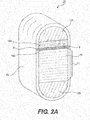
- FIGS. 2A through 2C show exemplary electrochemical cell stack compression systems 20, according to embodiments of the present disclosure.
- Each individual cell 10 may be stacked within compression system 20 to form an electrochemical cell stack 11.
- Stack 11 may be comprised of any suitable number of cells 10.
- Stack 11 may be located between end blocks 12A and 12B, which may be located at each end of stack 11.
- End blocks 12A, 12B may be formed of any suitable metal, plastic, or ceramic material having adequate compressive strength, e.g., aluminum, steel, stainless steel, cast iron, titanium, polyvinyl chloride, polyethylene, polypropylene, nylon, polyether ether ketone, alumina, or any combination thereof.
- Stack 11 and end blocks 12A, 12B may be housed in a structure 15.
- a wound fiber structure 15 may provide a resilient frame capable of housing a high-pressure electrochemical cell stack without significantly increasing the weight or size of the electrochemical cell system.
- Structure 15 may form a frame with a defined shape into which stack 11 and end blocks 12A, 12B are positioned.
- Figure 2A depicts an elongated, rounded, structure 15, but structure 15 may be any suitable shape, including, e.g., rectangular, oval, circular, or square.
- the walls of structure 15 may form a continuous border long the periphery of stack 11 and end blocks 12A, 12B, and structure 15 and may or may not enclose the front and/or back portions of stack 11 and end blocks 12A, 12B.
- End bocks 12A, 12B, stack 11, and any other components housed in structure 15 may be configured to lie flush with the walls of structure 15 on an open face, or the components may be recessed within structure 15 or they may protrude from structure 15, or any suitable combination thereof.
- Structure 15 may be dimensioned to house end blocks 12A, 12B and stack 11, which may include any suitable number of electrochemical cells 10.
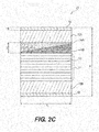
- the size, e.g., the height H, length L (shown in Figure 2C ), and/or width, of structure 15 may vary, for example, structure 15 may be configured to stretch during pre-loading, as discussed further below.
- Structure 15 may be dimensioned so as to snugly fit the desired contents, for example, electrochemical stack 11 and end blocks 12A, 12B, so as to not substantially increase the size of the overall electrochemical cell system.
- structure 15 may be formed of wound fibers that are capable of stretching and contracting.
- structure 15 may be formed of wound fibers, such as, e.g., carbon, glass, or aramid (e.g., KEVLAR®) fibers.
- the fibers may be non-conductive to reduce the likelihood of short-circuiting stack 11.
- structure 15 may be formed of metallic fibers, such as, e.g., steel, stainless steel, or aluminum, or alloys, such as Inconel.
- Structure 15 may be formed of homogenous fibers or a mixture of different fibers. Additionally, structure 15 may be formed with or without an epoxy matrix or other suitable material to bind the fibers together.
- the walls of structure 15 may have a thickness 't.'
- the wound fiber material properties, such as, e.g., tensile strength, and wall thickness t may be selected to achieve a desired compressive force on stack 11.
- the fibers making up structure 15 may be wound together to form one integral frame unit into which stack 11 and various other components fit.
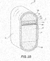
- structure 15 may be formed of multiple layers 13A, 13B, and 13C. Though Figure 2B depicts 3 layers, multi-layered embodiments of structure 15 may include any suitable number of layers. Each layer may be formed of homogenous fibers or of a combination of different fibers. The layers may be attached to one another, via, e.g., bonding or fastening mechanisms, or may be unattached and held together through, e.g., friction. Additionally, some layers may be attached while other layers may be unattached. In the multi-layer embodiments, structure 15 may include one or more slip-planes 4 between the layers.
- Slip-plane 4 may be formed of a separate layer or of a coating on one of the layers, such as, e.g., a polytetrafluoroethylene (e.g., TEFLON®), polyetheretherketone, polyimide, nylon, polyethylene, or polymer layer or coating, or any other suitable friction-reducing material to decrease the friction between the layers. If incorporated, slip-plane 4 may be included between each layer or may be included between fewer than all of the layers. The inclusion of slip-plane 4 may reduce the amount of stress within structure 15 and compression system 20, particularly in embodiments having thicker structure walls.
- a polytetrafluoroethylene e.g., TEFLON®
- polyetheretherketone polyimide
- nylon polyethylene
- polymer layer or coating any other suitable friction-reducing material to decrease the friction between the layers.
- slip-plane 4 may be included between each layer or may be included between fewer than all of the layers. The inclusion of slip-plane 4 may reduce the amount of stress within structure
- end blocks 12A, 12B may be also be configured to fit into structure 15 so that one or both of end blocks 12A, 12B may move within structure 15.
- end blocks 12A, 12B may be allowed to slip along the walls of structure 15. This configuration may decrease the stress in structure 15, which may in turn allow for structure 15 to incorporate thinner walls.
- end blocks 12A, 12B may include a suitable friction reducing material or coating, e.g., polytetrafluoroethylene (e.g., TEFLON®), polyetheretherketone, polyimide, nylon, polyethylene.
- end blocks 12A, 12B may be attached to the walls of structure 15 or may be otherwise configured so that end blocks 12A, 12B may not slip once inserted into structure 15.
- compression system 20 may include one or more gibs to promote uniform compression of electrochemical stack 11 within structure 15.
- the gibs may act as a wedge to drive two parallel planes in structure 15 apart as the gibs are wedged together in a direction perpendicular to the two parallel planes.
- gibs 14A, 14B may be inserted between electrochemical cell stack 11 and end block 12A to drive stack 11 and end block 12A apart while maintaining their parallel orientation.
- Gib 14B may have a flat surface and an opposite, angled surface. Gib 14B may be inserted into structure 15 so that the flat surface lies adjacent to stack 11 and the angled surface faces upwards.
- Gib 14B may be oriented so that the upward-facing, angled surface slopes in a downward direction toward the front face of structure 15 being loaded. Gib 14A may then be inserted next to gib 14B, and the two gibs may be driven together. Gib 14A may also have a flat surface and an opposite, angled surface sloped at an angle complimentary to the sloped surface of gib 14B. The angled surface of gib 14A may be inserted adjacent the angled surface of gib 14B so that the angled surface also slopes in downward direction towards the front face of structure 15. Thus, as gib 14A is inserted into structure 15 and driven against 14B, the complimentary slopes may slide against each other, pushing the flat surfaces of gibs 14A, 14B further apart from each other and towards end block 12A and stack 11. Gib 14A may be inserted into structure 15 until a desired compressive force is exerted on stack 11.
- Gib 14B may also include a grip portion configured to aid in the insertion and removal of gibs 14A, 14B from structure 15.
- gib 14B may include one or more gripping mechanism configured to engage the walls of structure 15 to reduce movement of gib 14B as gib 14A is inserted.
- the gripping mechanisms of gib 14B may engage an inner surface of structure 15 or may extend from gib 14B and engage an edge and/or outer surface of structure 15.
- Figure 2A depicts hooks 9 protruding outwards from gib 14B and engaging the edges of opposite walls of structure 15. Hooks 9 may prevent gib 14B from sliding further into structure 15 as gib 14A is inserted.
- Gib 14B may include any suitable gripping mechanism or combination of gripping mechanisms, such as, e.g., protrusions like pegs or hooks, or textured surfaces to reduce movement as gib 14A is wedged against gib 14B.
- the gripping mechanisms may be any suitable size, shape, and orientation.
- the thick end of gib 14B may be constrained against a fixed surface as gib 14A is driven, preventing translation against cell stack 11.
- gibs 14A, 14B may be included in any suitable position, for example, gibs 14A, 14B may be positioned between stack 11 and end block 12B, or sets of gibs may be located on either side of stack 11.
- Gibs 14A, 14B may be formed of any suitable material, such as, e.g., steel, stainless steel, ceramic, or aluminum. Gibs 14A, 14B may also have any suitable coating, such as a lubricant, to reduce galling or to facilitate insertion into compression system 20.
- a suitable friction reducing material may include, e.g., polytetrafluoroethylene (e.g., TEFLON®), polyetheretherketone, polyimide, nylon, polyethylene, or other lubricious polymer coatings, or any other suitable material.
- Gibs 14A, 14B may be any suitable shape and size for insertion into structure 15.
- the size and shape of gibs 14A, 14B may at least in part reflect the size and shape of the interior region of structure 15.
- Gibs 14A, 14B may be designed with any suitable angle.
- the angle that gibs 14A, 14B are designed with may be based, at least in part, on the required pre-load of stack 11, which may be based on the application of stack 11 and the accompanying output requirements.
- the size and shape of gibs 14A, 14B may also be based, in part, on the size of stack 11 compared to the size of structure 15.
- the same size structure 15 may be used to house stacks 11 of different sizes.
- larger gibs 14A, 14B may be used with smaller stacks 11 to apply an appropriate compressive force, and vice versa.
- Gibs 14A, 14B may be used to apply compression to stack 11, maintain a uniform load, stabilize system 20, and provide planarity.
- components of compression system 20, such as stack 11 and end blocks 12A, 12B may be inserted into structure 15.
- structure 15 may be "pre-loaded” or pre-stretched to apply a predetermined compressive force to stack 11 in order to maintain contact between electrochemical cells 10. This may be accomplished using compressive mechanisms, such as gibs 14A, 14B. Once the other components are inserted, gibs 14A, 14B may be inserted into structure 15 to fill any gaps.
- Gibs 14A, 14B may be wedged against each other until their parallel surfaces are forced apart far enough to achieve a desired compressive load on the surrounding components, e.g., stack 11, within structure 15.
- tension within the walls of wound fiber structure 15 may increase, and the fibers may stretch. This may increase the height H of structure 15.
- the amount of expansion of structure 15 may depend, at least in part, on the wall thickness t and the types of fibers that make up structure 15. Measuring the change in height H of structure 15 during pre-loading may indicate the compressive force being applied to stack 11 and may allow for more precise control of pre-loading conditions.
- system 20 may provide a lightweight, low-cost system for accurately and effectively applying a compressive load to stack 11.
- structure 15 may begin to stretch more than its pre-loaded value.
- structure 15 may be forced to stretch more than the pre-loaded value due to differential thermal expansion and the force applied to the stack will increase.
- the materials of structure 15 and any compressive mechanisms may be selected based on their thermal properties to reduce the potential for loss of compressive force during operation.
- system 20 may include other compressive mechanisms instead of, or in addition to, gibs 14A, 14B.
- one or more thermal expansion blocks 21 may be used to apply compression to stack 11.
- Block 21 may be cooled to a temperature below that of stack 11.
- cooled block 21 may be inserted into compression system 20.
- Block 21 may expand, and accordingly, may apply compression to stack 11.
- Block 21 may be formed of any material or combination of materials having suitable thermal expansion characteristics, such as, e.g., suitable metals, metal alloys, or ceramics.
- block 21 may be formed of materials with a higher coefficient of thermal expansion than that of structure 15. In such embodiments, as stack 11 and block 21 are brought up to operating temperature (generally between 30 and 100°C), block 21 may expand more than structure 15. Such expansion may result in compressive loading of stack 11.
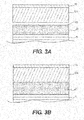
- block 21 may be easier to insert into structure 15. Inserting block 21 prior to thermal expansion may reduce the wear and stress on the surrounding components of compression system 20. For example, as is shown in Figure 3A , when block 21 is initially inserted during pre-loading, a gap 17 may exist in compression system 20. As block 21 warms, gap 17 may disappear as block 21 expands and fills the surrounding space (shown in Figure 3B ). Once gap 17 disappears, the continued expansion of block 21 may begin to compress stack 11 and apply a compressive load.
- the thermal properties of block 21 may be chosen to impart a desired compressive load based on the size of stack 11 and the size of gap 17 in structure 15. It will be understood that while gap 17 is shown between inserted block 21 and end block 12A, block 21 may be oriented so that gap 17 occurs on either side of block 21, or on both sides of block 21. Further, gap 17 may occur in any region within structure 15.
- block 21 is herein described as the expansion member, one or more of end blocks 12A or 12B may be designed to provide thermal compression instead of, or in addition to, block 21. Further, gibs 14A, 14B may also be made of suitable material to allow them to apply compression via use as a wedge as well as through thermal expansion. Additionally, multiple thermal expansion blocks 21 may be used, or a combination of thermal expansion block 21 and gibs 14A, 14B may be inserted into structure 15.
- a screw compression unit 19 with internal drive screws may be used to apply a compressive load.
- Compression unit 19 may be configured to be removable from structure 15 or may be attached to structure 15.
- threaded screws 18 may extend from a base 16B of compression unit 19. The opposite ends of screws 18 may extend into complimentary threaded inlets (not shown) in block 16A of compression unit 19. Rotating screws 18 in one direction may cause screws 18 to screw further into the threaded inlets in block 16A, moving block 16A closer to base 16B and decreasing the gap between 16A and 16B. Decreasing the gap between 16A and 16B may reduce the compressive force applied to stack 11.
- Rotating screws 18 in the opposite direction may cause screws 18 to unscrew from the threaded inlets in block 16A, moving block 16A away from base 16B and increasing the gap between 16A and 16B. Increasing the gap between 16A and 16B may increase the compressive force applied to stack 11.
- compression unit 19 may be inserted into structure 15 while there is little or no gap between block 16A and base 16B. Once inserted, screws 18 may be rotated so as to increase the gap between block 16A and base 16B in order to apply a desired compressive force to stack 11.
- any suitable number of threaded components may be included in compression unit 19. Additionally, the threaded components may be distributed on base 16B in any suitable arrangement. Screws 18 may be any suitable shape or size and may be formed of any suitable material, for example, any metal, metal alloy, or ceramic. Any number of compression units 19 may be incorporated in system 20, and compression unit 19 may be used in place of or in addition to either or both of gibs 14A, 14B and thermal expansion block 21. Further, in some embodiments, compression unit 19 may also be incorporated into one of the components or compression mechanisms described previously. For example, one or more of end blocks 12A, 12B, gibs 14A, 14B, or block 21 may include internal drive screws.
- compression system 20 may accommodate electrochemical stacks of different sizes.
- structure 15 may be configured to receive electrochemical cell stacks of different sizes with different numbers of electrochemical cells suitable for different applications and output levels. If a smaller stack 11 with fewer electrochemical cells 10 is contained in structure 15, then larger compression mechanisms or a larger number of or combination of compression mechanisms may be inserted around stack 11 during pre-loading to fill any additional space and apply a desired compressive force. Alternatively, if a larger electrochemical cell stack 11 with more cells 10 is housed in structure 15, smaller compression mechanisms or fewer compression mechanisms may be inserted around stack 11.
- the same basic structure 15 may be capable of housing different sized electrochemical cell stacks appropriate for different applications and different output levels. This may reduce manufacturing costs, because one standard structure 15 may be produced for housing a variety of electrochemical cell stack sizes suitable for a variety of applications. Thus, the same basic technology may produce structures for stacks of various cell counts and sizes. By incorporating different numbers of or different types of compression mechanisms described above, the same structure 15 may be capable of accommodating a range of operating conditions over an extended period of time.
- structure 15 may be configured so that one or more of the layers is removable or separable from the other layers.
- one or more of the layers may be nested within another layer and may be capable of being completely removed from the surrounding layer.
- layer 13A may be nested within and removable from layer 13B, for example, and slip-plane 4 may facilitate removal.
- one or more layers may be removed to adapt structure 15 to the currently applicable operating conditions.
- Application of embodiments described above may improve performance of electrochemical cells, including electrochemical cells operating under high-pressure conditions.
Landscapes
- Chemical & Material Sciences (AREA)
- Electrochemistry (AREA)
- Engineering & Computer Science (AREA)
- Chemical Kinetics & Catalysis (AREA)
- Organic Chemistry (AREA)
- Metallurgy (AREA)
- Materials Engineering (AREA)
- General Chemical & Material Sciences (AREA)
- Life Sciences & Earth Sciences (AREA)
- Sustainable Energy (AREA)
- Sustainable Development (AREA)
- Manufacturing & Machinery (AREA)
- Inorganic Chemistry (AREA)
- Electrolytic Production Of Non-Metals, Compounds, Apparatuses Therefor (AREA)
- Fuel Cell (AREA)
- Secondary Cells (AREA)
Claims (14)
- Elektrochemisches Zellenstapelkompressionssystem (20), umfassend:eine integrale, hohle Struktur (15) mit einer definierten Form und gebildet aus einer Mehrzahl gewickelter Fasern, wobei die Struktur aus mehreren Schichten (13A, 13B, 13C) ausgebildet ist;eine Mehrzahl elektrochemischer Zellen (10), die in einer Reihe entlang einer Achse angeordnet sind, so dass sie einen elektrochemischen Stapel (11) bilden, wobei sich der elektrochemische Stapel (11) in der Struktur (15) befindet;mindestens einen Endblock (12A, 12B), der sich in der Struktur (15) befindet und an einem Endbereich der Struktur (15) angeordnet ist; undmindestens einen Kompressionsmechanismus (14A, 14B, 21, 19), der sich in der Struktur (15) befindet, wobei der mindestens eine Kompressionsmechanismus (14A, 14B, 21, 19) so gestaltet ist, dass er eine Kompressionskraft auf den elektrochemischen Stapel (11) ausübt;wobei der elektrochemische Stapel (11), der mindestens eine Endblock (12A, 12B) und der mindestens eine Kompressionsmechanismus (14A, 14B, 21, 19) in Reihe in der Struktur (15) angeordnet sind, so dass die Struktur (15) eine ununterbrochene Begrenzung um und angrenzend an eine Peripherie des elektrochemischen Stapels (11), des mindestens einen Endblocks (12A, 12B) und den mindestens einen Kompressionsmechanismus (14A, 14B, 21, 19) bildet.
- Kompressionssystem nach Anspruch 1, wobei die Fasern so gestaltet sind, dass sie sich als Reaktion auf Veränderungen der Kompressionskraft dehnen und zusammenziehen.
- Kompressionssystem nach Anspruch 1, wobei der mindestens eine Kompressionsmechanismus eine Leiste (14A, 14B) umfasst.
- Kompressionssystem nach Anspruch 1, wobei jede Schicht aus homogenen Fasern gebildet ist.
- Kompressionssystem nach Anspruch 1, wobei jede Schicht aus einer Kombination von Fasern verschiedener Materialien gebildet ist.
- Kompressionssystem nach Anspruch 1, wobei mindestens zwei der Schichten durch Bonding- oder Befestigungsmechanismen befestigt sind.
- Kompressionssystem nach Anspruch 1, wobei mindestens zwei der Schichten unbefestigt sind und durch Reibung an ihrer Position gehalten werden.
- Kompressionssystem nach Anspruch 1, wobei die mehreren Schichten einige befestigte Schichten und weitere unbefestigte Schichten aufweisen.
- Kompressionssystem nach Anspruch 1, wobei die Struktur eine Reibungsreduzierungsschicht (4) aufweist, die sich zwischen wenigstens zwei der mehreren Schichten befindet.
- Kompressionssystem nach Anspruch 1, wobei wenigstens ein Teil der gewickelten Fasern Kohlenstofffasern sind.
- Kompressionssystem nach Anspruch 1, wobei das Kompressionssystem eine erste Leiste (14A) und eine zweite Leiste (14B) umfasst, eingeführt zwischen dem Stapel (11) und dem mindestens einen Endblock (12A, 12B), wobei die erste (14A) und die zweite Leiste (14B) jeweils eine flache Oberfläche und eine entgegengesetzte angewinkelte Oberfläche aufweisen, wobei die flache Oberfläche der ersten Leiste (14A) flach angrenzend an den Stapel angeordnet ist, und wobei die angewinkelte Oberfläche einer zweiten Leiste (14B) in einem Winkel geneigt ist, der komplementär ist zu der angewinkelten Oberfläche der ersten Leiste (14A), und wobei sie angrenzend an die angewinkelte Oberfläche der ersten Leiste (14A) eingeführt ist.
- Kompressionssystem nach Anspruch 1, wobei der Kompressionsmechanismus eine oder mehrere innere Antriebsschrauben (18) aufweist, die in der Struktur positioniert sind, wobei eine Rotation der inneren Antriebsschrauben (18) in eine Richtung den Stapel komprimiert, und wobei eine Rotation der inneren Antriebsschreiben (18) in die entgegengesetzte Richtung den Stapel dekomprimiert.
- Kompressionssystem nach Anspruch 1, wobei die Struktur zwei entgegengesetzte Wandoberflächen aufweist, die durch abgerundete runde Enden verbunden sind.
- Verfahren zur Vorbelastung des Kompressionssystems nach Anspruch 1, wobei das Verfahren folgendes umfasst:Einführen des elektrochemischen Stapels (11) in die hohle Struktur (15);Einführen des mindestens einen Endblocks (12A, 12B) in die hohle Struktur (15);Einführen des mindestens einen Kompressionsmechanismus (14A, 14B, 21, 19) in die hohle Struktur (15);Gestalten des Kompressionsmechanismus (14A, 14B, 21, 19), so dass eine vorbestimmte Belastung in dem Kompressionssystem ausgeübt wird; undMessen einer Veränderung der Höhe der Struktur (15) entlang der Achse des elektrochemischen Stapels (11), um die durch den Kompressionsmechanismus (14A, 14B, 21, 19) ausgeübte Belastung zu bestimmen.
Applications Claiming Priority (3)
| Application Number | Priority Date | Filing Date | Title |
|---|---|---|---|
| US201361775068P | 2013-03-08 | 2013-03-08 | |
| EP14709057.5A EP2965378B1 (de) | 2013-03-08 | 2014-02-19 | Elektrochemischer stapel |
| PCT/US2014/017195 WO2014137601A2 (en) | 2013-03-08 | 2014-02-19 | Electrochemical stack compression system |
Related Parent Applications (1)
| Application Number | Title | Priority Date | Filing Date |
|---|---|---|---|
| EP14709057.5A Division EP2965378B1 (de) | 2013-03-08 | 2014-02-19 | Elektrochemischer stapel |
Publications (2)
| Publication Number | Publication Date |
|---|---|
| EP3557673A1 EP3557673A1 (de) | 2019-10-23 |
| EP3557673B1 true EP3557673B1 (de) | 2020-11-25 |
Family
ID=50240005
Family Applications (2)
| Application Number | Title | Priority Date | Filing Date |
|---|---|---|---|
| EP19177224.3A Active EP3557673B1 (de) | 2013-03-08 | 2014-02-19 | Elektrochemischer stapel |
| EP14709057.5A Active EP2965378B1 (de) | 2013-03-08 | 2014-02-19 | Elektrochemischer stapel |
Family Applications After (1)
| Application Number | Title | Priority Date | Filing Date |
|---|---|---|---|
| EP14709057.5A Active EP2965378B1 (de) | 2013-03-08 | 2014-02-19 | Elektrochemischer stapel |
Country Status (10)
| Country | Link |
|---|---|
| US (2) | US10109880B2 (de) |
| EP (2) | EP3557673B1 (de) |
| JP (2) | JP6609189B2 (de) |
| KR (1) | KR20150128826A (de) |
| CN (2) | CN105122528B (de) |
| AU (2) | AU2014226462B2 (de) |
| BR (1) | BR112015017429A2 (de) |
| CA (1) | CA2898226A1 (de) |
| ES (2) | ES2837698T3 (de) |
| WO (1) | WO2014137601A2 (de) |
Families Citing this family (7)
| Publication number | Priority date | Publication date | Assignee | Title |
|---|---|---|---|---|
| JP6646427B2 (ja) * | 2015-12-15 | 2020-02-14 | 豊田鉄工株式会社 | 電池ケース |
| GB2563848B (en) * | 2017-06-26 | 2022-01-12 | Ceres Ip Co Ltd | Fuel cell stack assembly |
| DE102017215510A1 (de) | 2017-09-05 | 2019-03-07 | Volkswagen Ag | Verfahren zum Bestimmen der auf einen Brennstoffzellenstapel wirkenden Kompressionszugkraft |
| CN212119505U (zh) * | 2018-12-30 | 2020-12-11 | 熵零技术逻辑工程院集团股份有限公司 | 一种压缩装置 |
| KR102346856B1 (ko) * | 2020-01-15 | 2022-01-04 | 한국에너지기술연구원 | 출력 밀도 향상 및 적층이 용이한 흐름식 에너지 저장장치 셀스택의 체결구조 및 이를 적용한 흐름식 에너지 저장장치 |
| BR112022019801A2 (pt) | 2020-03-31 | 2022-11-16 | Plug Power Inc | Método e sistema para compressão eletroquímica de hidrogênio gasoso |
| US11746427B2 (en) * | 2021-07-05 | 2023-09-05 | EvolOH, Inc. | Scalable electrolysis cell and stack and method of high-speed manufacturing the same |
Family Cites Families (24)
| Publication number | Priority date | Publication date | Assignee | Title |
|---|---|---|---|---|
| JPH06188023A (ja) * | 1992-12-22 | 1994-07-08 | Fuji Electric Co Ltd | 平板形固体電解質燃料電池 |
| JP3505010B2 (ja) * | 1995-07-07 | 2004-03-08 | 本田技研工業株式会社 | 燃料電池およびその締付方法 |
| US5789091C1 (en) | 1996-11-19 | 2001-02-27 | Ballard Power Systems | Electrochemical fuel cell stack with compression bands |
| JP2002063929A (ja) * | 2000-08-14 | 2002-02-28 | Sony Corp | 燃料電池のスタック構造 |
| US6663996B2 (en) | 2000-12-22 | 2003-12-16 | Ballard Power Systems Inc. | Compression mechanism for an electrochemical fuel cell assembly |
| US20030072545A1 (en) * | 2001-10-12 | 2003-04-17 | Fujikura Ltd. | Drop cable and method of fabricating same |
| US6862801B2 (en) | 2001-11-30 | 2005-03-08 | Ballard Power Systems Inc. | Systems, apparatus and methods for isolating, compressing and/or retaining the structure of a fuel cell stack |
| AT5881U1 (de) * | 2002-05-13 | 2003-01-27 | Zeug Design G M B H | Rollschuh |
| JP2004327125A (ja) * | 2003-04-22 | 2004-11-18 | Nissan Motor Co Ltd | 外部マニホルド型燃料電池 |
| CN100435399C (zh) * | 2004-01-20 | 2008-11-19 | 株式会社日立制作所 | 燃料电池用燃料容器 |
| US20060093890A1 (en) * | 2004-10-29 | 2006-05-04 | Steinbroner Matthew P | Fuel cell stack compression systems, and fuel cell stacks and fuel cell systems incorporating the same |
| US7294427B2 (en) * | 2004-12-27 | 2007-11-13 | Fuelcell Energy, Inc. | Manifold gasket accommodating differential movement of fuel cell stack |
| FI20055017A (fi) * | 2005-01-13 | 2006-07-14 | Waertsilae Finland Oy | Järjestely polttokennojen puristamiseksi polttokennopinossa |
| DE102006030605A1 (de) * | 2006-07-03 | 2008-01-10 | Webasto Ag | Anordnung mit einem Brennstoffzellenstapel und Verfahren zum Verspannen eines Brennstoffzellenstapels |
| ES2385902T3 (es) * | 2006-07-14 | 2012-08-02 | Topsoe Fuel Cell A/S | Conjunto de compresión, bloque de pilas de combustible de óxido sólido, un procedimiento para la compresión del bloque de pilas de combustible de óxido sólido y su utilización |
| JP4910707B2 (ja) * | 2007-01-05 | 2012-04-04 | トヨタ自動車株式会社 | 燃料電池 |
| DK2109912T3 (da) * | 2007-01-26 | 2011-01-10 | Topsoe Fuel Cell As | Klemstruktur til brænselcellestak samt faststofoxidbrændselcellestak |
| US8007951B2 (en) * | 2007-06-08 | 2011-08-30 | GM Global Technology Operations LLC | Fuel cell compression retention system using compliant strapping |
| KR100986456B1 (ko) * | 2008-03-04 | 2010-10-08 | 포항공과대학교 산학협력단 | 연료전지스택 체결 장치 |
| JP5449411B2 (ja) * | 2009-03-13 | 2014-03-19 | トプサー・フューエル・セル・アクチエゼルスカベット | 燃料電池スタックのための圧縮ケーシング及び燃料電池スタックのための圧縮ケーシングの製造方法 |
| JP5448116B2 (ja) * | 2009-04-01 | 2014-03-19 | エルジー・ケム・リミテッド | 向上させた安全性を有するバッテリーモジュール |
| US9331321B2 (en) * | 2011-03-31 | 2016-05-03 | GM Global Technology Operations LLC | Fabric composite support or enclosure for an automotive battery pack |
| EP2546915B1 (de) | 2011-07-11 | 2014-06-11 | Belenos Clean Power Holding AG | Gehäuseanordnung für einen Brennstoffzellenstapel |
| JP5684665B2 (ja) * | 2011-07-13 | 2015-03-18 | 本田技研工業株式会社 | 燃料電池スタック |
-
2014
- 2014-02-19 CN CN201480012808.XA patent/CN105122528B/zh active Active
- 2014-02-19 JP JP2015561380A patent/JP6609189B2/ja active Active
- 2014-02-19 KR KR1020157027579A patent/KR20150128826A/ko not_active Application Discontinuation
- 2014-02-19 BR BR112015017429A patent/BR112015017429A2/pt not_active Application Discontinuation
- 2014-02-19 CA CA2898226A patent/CA2898226A1/en not_active Abandoned
- 2014-02-19 EP EP19177224.3A patent/EP3557673B1/de active Active
- 2014-02-19 ES ES19177224T patent/ES2837698T3/es active Active
- 2014-02-19 CN CN201910760568.6A patent/CN110429314A/zh active Pending
- 2014-02-19 WO PCT/US2014/017195 patent/WO2014137601A2/en active Application Filing
- 2014-02-19 ES ES14709057T patent/ES2734527T3/es active Active
- 2014-02-19 EP EP14709057.5A patent/EP2965378B1/de active Active
- 2014-02-19 AU AU2014226462A patent/AU2014226462B2/en active Active
- 2014-03-05 US US14/198,317 patent/US10109880B2/en active Active
-
2018
- 2018-06-20 AU AU2018204418A patent/AU2018204418A1/en not_active Abandoned
- 2018-09-18 US US16/133,804 patent/US20190020051A1/en not_active Abandoned
-
2019
- 2019-10-25 JP JP2019194139A patent/JP2020031062A/ja not_active Ceased
Non-Patent Citations (1)
| Title |
|---|
| None * |
Also Published As
| Publication number | Publication date |
|---|---|
| US20190020051A1 (en) | 2019-01-17 |
| JP2016514351A (ja) | 2016-05-19 |
| JP6609189B2 (ja) | 2019-11-20 |
| CN110429314A (zh) | 2019-11-08 |
| JP2020031062A (ja) | 2020-02-27 |
| BR112015017429A2 (pt) | 2017-07-11 |
| ES2837698T3 (es) | 2021-07-01 |
| WO2014137601A3 (en) | 2014-11-06 |
| WO2014137601A2 (en) | 2014-09-12 |
| US10109880B2 (en) | 2018-10-23 |
| KR20150128826A (ko) | 2015-11-18 |
| ES2734527T3 (es) | 2019-12-10 |
| EP3557673A1 (de) | 2019-10-23 |
| AU2018204418A1 (en) | 2018-07-12 |
| EP2965378B1 (de) | 2019-06-19 |
| US20140255817A1 (en) | 2014-09-11 |
| AU2014226462B2 (en) | 2018-03-29 |
| AU2014226462A1 (en) | 2015-10-08 |
| EP2965378A2 (de) | 2016-01-13 |
| CN105122528A (zh) | 2015-12-02 |
| CA2898226A1 (en) | 2014-09-12 |
| CN105122528B (zh) | 2019-09-10 |
Similar Documents
| Publication | Publication Date | Title |
|---|---|---|
| US20190020051A1 (en) | Electrochemical stack compression system | |
| US10305124B2 (en) | Resilient flow structures for electrochemical cell | |
| US7851102B2 (en) | Fuel cell stack compression retention system using overlapping sheets | |
| US10727501B2 (en) | Bipolar plate having a polymeric coating | |
| CA2881864A1 (en) | Design of bipolar plates for use in electrochemical cells | |
| US20130034790A1 (en) | Fuel cell stack having a structural heat exchanger | |
| JP2006506780A (ja) | 燃料電池スタック | |
| Kim et al. | Fuel cell end plates: a review | |
| GB2505693A (en) | A proton exchange membrane fuel cell with open pore cellular foam | |
| US20220320532A1 (en) | Fuel cell unit | |
| EP3335263A1 (de) | Mehrkomponentige bipolare platte für eine batteriezelle |
Legal Events
| Date | Code | Title | Description |
|---|---|---|---|
| PUAI | Public reference made under article 153(3) epc to a published international application that has entered the european phase |
Free format text: ORIGINAL CODE: 0009012 |
|
| STAA | Information on the status of an ep patent application or granted ep patent |
Free format text: STATUS: THE APPLICATION HAS BEEN PUBLISHED |
|
| AC | Divisional application: reference to earlier application |
Ref document number: 2965378 Country of ref document: EP Kind code of ref document: P |
|
| AK | Designated contracting states |
Kind code of ref document: A1 Designated state(s): AL AT BE BG CH CY CZ DE DK EE ES FI FR GB GR HR HU IE IS IT LI LT LU LV MC MK MT NL NO PL PT RO RS SE SI SK SM TR |
|
| STAA | Information on the status of an ep patent application or granted ep patent |
Free format text: STATUS: REQUEST FOR EXAMINATION WAS MADE |
|
| 17P | Request for examination filed |
Effective date: 20200423 |
|
| RBV | Designated contracting states (corrected) |
Designated state(s): AL AT BE BG CH CY CZ DE DK EE ES FI FR GB GR HR HU IE IS IT LI LT LU LV MC MK MT NL NO PL PT RO RS SE SI SK SM TR |
|
| GRAP | Despatch of communication of intention to grant a patent |
Free format text: ORIGINAL CODE: EPIDOSNIGR1 |
|
| STAA | Information on the status of an ep patent application or granted ep patent |
Free format text: STATUS: GRANT OF PATENT IS INTENDED |
|
| INTG | Intention to grant announced |
Effective date: 20200612 |
|
| GRAS | Grant fee paid |
Free format text: ORIGINAL CODE: EPIDOSNIGR3 |
|
| GRAA | (expected) grant |
Free format text: ORIGINAL CODE: 0009210 |
|
| STAA | Information on the status of an ep patent application or granted ep patent |
Free format text: STATUS: THE PATENT HAS BEEN GRANTED |
|
| AC | Divisional application: reference to earlier application |
Ref document number: 2965378 Country of ref document: EP Kind code of ref document: P |
|
| AK | Designated contracting states |
Kind code of ref document: B1 Designated state(s): AL AT BE BG CH CY CZ DE DK EE ES FI FR GB GR HR HU IE IS IT LI LT LU LV MC MK MT NL NO PL PT RO RS SE SI SK SM TR |
|
| REG | Reference to a national code |
Ref country code: GB Ref legal event code: FG4D |
|
| REG | Reference to a national code |
Ref country code: CH Ref legal event code: EP |
|
| REG | Reference to a national code |
Ref country code: DE Ref legal event code: R096 Ref document number: 602014072838 Country of ref document: DE |
|
| REG | Reference to a national code |
Ref country code: AT Ref legal event code: REF Ref document number: 1339328 Country of ref document: AT Kind code of ref document: T Effective date: 20201215 |
|
| REG | Reference to a national code |
Ref country code: IE Ref legal event code: FG4D |
|
| REG | Reference to a national code |
Ref country code: AT Ref legal event code: MK05 Ref document number: 1339328 Country of ref document: AT Kind code of ref document: T Effective date: 20201125 |
|
| REG | Reference to a national code |
Ref country code: NL Ref legal event code: MP Effective date: 20201125 |
|
| PG25 | Lapsed in a contracting state [announced via postgrant information from national office to epo] |
Ref country code: GR Free format text: LAPSE BECAUSE OF FAILURE TO SUBMIT A TRANSLATION OF THE DESCRIPTION OR TO PAY THE FEE WITHIN THE PRESCRIBED TIME-LIMIT Effective date: 20210226 Ref country code: NO Free format text: LAPSE BECAUSE OF FAILURE TO SUBMIT A TRANSLATION OF THE DESCRIPTION OR TO PAY THE FEE WITHIN THE PRESCRIBED TIME-LIMIT Effective date: 20210225 Ref country code: FI Free format text: LAPSE BECAUSE OF FAILURE TO SUBMIT A TRANSLATION OF THE DESCRIPTION OR TO PAY THE FEE WITHIN THE PRESCRIBED TIME-LIMIT Effective date: 20201125 Ref country code: RS Free format text: LAPSE BECAUSE OF FAILURE TO SUBMIT A TRANSLATION OF THE DESCRIPTION OR TO PAY THE FEE WITHIN THE PRESCRIBED TIME-LIMIT Effective date: 20201125 Ref country code: PT Free format text: LAPSE BECAUSE OF FAILURE TO SUBMIT A TRANSLATION OF THE DESCRIPTION OR TO PAY THE FEE WITHIN THE PRESCRIBED TIME-LIMIT Effective date: 20210325 |
|
| PG25 | Lapsed in a contracting state [announced via postgrant information from national office to epo] |
Ref country code: AT Free format text: LAPSE BECAUSE OF FAILURE TO SUBMIT A TRANSLATION OF THE DESCRIPTION OR TO PAY THE FEE WITHIN THE PRESCRIBED TIME-LIMIT Effective date: 20201125 Ref country code: LV Free format text: LAPSE BECAUSE OF FAILURE TO SUBMIT A TRANSLATION OF THE DESCRIPTION OR TO PAY THE FEE WITHIN THE PRESCRIBED TIME-LIMIT Effective date: 20201125 Ref country code: PL Free format text: LAPSE BECAUSE OF FAILURE TO SUBMIT A TRANSLATION OF THE DESCRIPTION OR TO PAY THE FEE WITHIN THE PRESCRIBED TIME-LIMIT Effective date: 20201125 Ref country code: IS Free format text: LAPSE BECAUSE OF FAILURE TO SUBMIT A TRANSLATION OF THE DESCRIPTION OR TO PAY THE FEE WITHIN THE PRESCRIBED TIME-LIMIT Effective date: 20210325 Ref country code: SE Free format text: LAPSE BECAUSE OF FAILURE TO SUBMIT A TRANSLATION OF THE DESCRIPTION OR TO PAY THE FEE WITHIN THE PRESCRIBED TIME-LIMIT Effective date: 20201125 Ref country code: BG Free format text: LAPSE BECAUSE OF FAILURE TO SUBMIT A TRANSLATION OF THE DESCRIPTION OR TO PAY THE FEE WITHIN THE PRESCRIBED TIME-LIMIT Effective date: 20210225 |
|
| REG | Reference to a national code |
Ref country code: LT Ref legal event code: MG9D |
|
| PG25 | Lapsed in a contracting state [announced via postgrant information from national office to epo] |
Ref country code: HR Free format text: LAPSE BECAUSE OF FAILURE TO SUBMIT A TRANSLATION OF THE DESCRIPTION OR TO PAY THE FEE WITHIN THE PRESCRIBED TIME-LIMIT Effective date: 20201125 |
|
| PG25 | Lapsed in a contracting state [announced via postgrant information from national office to epo] |
Ref country code: SM Free format text: LAPSE BECAUSE OF FAILURE TO SUBMIT A TRANSLATION OF THE DESCRIPTION OR TO PAY THE FEE WITHIN THE PRESCRIBED TIME-LIMIT Effective date: 20201125 Ref country code: SK Free format text: LAPSE BECAUSE OF FAILURE TO SUBMIT A TRANSLATION OF THE DESCRIPTION OR TO PAY THE FEE WITHIN THE PRESCRIBED TIME-LIMIT Effective date: 20201125 Ref country code: EE Free format text: LAPSE BECAUSE OF FAILURE TO SUBMIT A TRANSLATION OF THE DESCRIPTION OR TO PAY THE FEE WITHIN THE PRESCRIBED TIME-LIMIT Effective date: 20201125 Ref country code: CZ Free format text: LAPSE BECAUSE OF FAILURE TO SUBMIT A TRANSLATION OF THE DESCRIPTION OR TO PAY THE FEE WITHIN THE PRESCRIBED TIME-LIMIT Effective date: 20201125 Ref country code: LT Free format text: LAPSE BECAUSE OF FAILURE TO SUBMIT A TRANSLATION OF THE DESCRIPTION OR TO PAY THE FEE WITHIN THE PRESCRIBED TIME-LIMIT Effective date: 20201125 Ref country code: RO Free format text: LAPSE BECAUSE OF FAILURE TO SUBMIT A TRANSLATION OF THE DESCRIPTION OR TO PAY THE FEE WITHIN THE PRESCRIBED TIME-LIMIT Effective date: 20201125 |
|
| REG | Reference to a national code |
Ref country code: DE Ref legal event code: R097 Ref document number: 602014072838 Country of ref document: DE |
|
| PG25 | Lapsed in a contracting state [announced via postgrant information from national office to epo] |
Ref country code: DK Free format text: LAPSE BECAUSE OF FAILURE TO SUBMIT A TRANSLATION OF THE DESCRIPTION OR TO PAY THE FEE WITHIN THE PRESCRIBED TIME-LIMIT Effective date: 20201125 |
|
| PG25 | Lapsed in a contracting state [announced via postgrant information from national office to epo] |
Ref country code: MC Free format text: LAPSE BECAUSE OF FAILURE TO SUBMIT A TRANSLATION OF THE DESCRIPTION OR TO PAY THE FEE WITHIN THE PRESCRIBED TIME-LIMIT Effective date: 20201125 |
|
| PLBE | No opposition filed within time limit |
Free format text: ORIGINAL CODE: 0009261 |
|
| STAA | Information on the status of an ep patent application or granted ep patent |
Free format text: STATUS: NO OPPOSITION FILED WITHIN TIME LIMIT |
|
| REG | Reference to a national code |
Ref country code: BE Ref legal event code: MM Effective date: 20210228 |
|
| PG25 | Lapsed in a contracting state [announced via postgrant information from national office to epo] |
Ref country code: AL Free format text: LAPSE BECAUSE OF FAILURE TO SUBMIT A TRANSLATION OF THE DESCRIPTION OR TO PAY THE FEE WITHIN THE PRESCRIBED TIME-LIMIT Effective date: 20201125 Ref country code: NL Free format text: LAPSE BECAUSE OF FAILURE TO SUBMIT A TRANSLATION OF THE DESCRIPTION OR TO PAY THE FEE WITHIN THE PRESCRIBED TIME-LIMIT Effective date: 20201125 Ref country code: CH Free format text: LAPSE BECAUSE OF NON-PAYMENT OF DUE FEES Effective date: 20210228 Ref country code: LU Free format text: LAPSE BECAUSE OF NON-PAYMENT OF DUE FEES Effective date: 20210219 Ref country code: LI Free format text: LAPSE BECAUSE OF NON-PAYMENT OF DUE FEES Effective date: 20210228 |
|
| 26N | No opposition filed |
Effective date: 20210826 |
|
| PG25 | Lapsed in a contracting state [announced via postgrant information from national office to epo] |
Ref country code: SI Free format text: LAPSE BECAUSE OF FAILURE TO SUBMIT A TRANSLATION OF THE DESCRIPTION OR TO PAY THE FEE WITHIN THE PRESCRIBED TIME-LIMIT Effective date: 20201125 |
|
| PG25 | Lapsed in a contracting state [announced via postgrant information from national office to epo] |
Ref country code: IE Free format text: LAPSE BECAUSE OF NON-PAYMENT OF DUE FEES Effective date: 20210219 |
|
| PG25 | Lapsed in a contracting state [announced via postgrant information from national office to epo] |
Ref country code: IS Free format text: LAPSE BECAUSE OF FAILURE TO SUBMIT A TRANSLATION OF THE DESCRIPTION OR TO PAY THE FEE WITHIN THE PRESCRIBED TIME-LIMIT Effective date: 20210325 |
|
| PG25 | Lapsed in a contracting state [announced via postgrant information from national office to epo] |
Ref country code: BE Free format text: LAPSE BECAUSE OF NON-PAYMENT OF DUE FEES Effective date: 20210228 |
|
| PG25 | Lapsed in a contracting state [announced via postgrant information from national office to epo] |
Ref country code: CY Free format text: LAPSE BECAUSE OF FAILURE TO SUBMIT A TRANSLATION OF THE DESCRIPTION OR TO PAY THE FEE WITHIN THE PRESCRIBED TIME-LIMIT Effective date: 20201125 |
|
| PG25 | Lapsed in a contracting state [announced via postgrant information from national office to epo] |
Ref country code: HU Free format text: LAPSE BECAUSE OF FAILURE TO SUBMIT A TRANSLATION OF THE DESCRIPTION OR TO PAY THE FEE WITHIN THE PRESCRIBED TIME-LIMIT; INVALID AB INITIO Effective date: 20140219 |
|
| PGFP | Annual fee paid to national office [announced via postgrant information from national office to epo] |
Ref country code: ES Payment date: 20240305 Year of fee payment: 11 |
|
| PG25 | Lapsed in a contracting state [announced via postgrant information from national office to epo] |
Ref country code: MK Free format text: LAPSE BECAUSE OF FAILURE TO SUBMIT A TRANSLATION OF THE DESCRIPTION OR TO PAY THE FEE WITHIN THE PRESCRIBED TIME-LIMIT Effective date: 20201125 |
|
| PGFP | Annual fee paid to national office [announced via postgrant information from national office to epo] |
Ref country code: DE Payment date: 20240109 Year of fee payment: 11 Ref country code: GB Payment date: 20240108 Year of fee payment: 11 |
|
| PGFP | Annual fee paid to national office [announced via postgrant information from national office to epo] |
Ref country code: IT Payment date: 20231215 Year of fee payment: 11 Ref country code: FR Payment date: 20240112 Year of fee payment: 11 |