EP3557599B1 - Niederspannungsschutzschalter - Google Patents
Niederspannungsschutzschalter Download PDFInfo
- Publication number
- EP3557599B1 EP3557599B1 EP18168308.7A EP18168308A EP3557599B1 EP 3557599 B1 EP3557599 B1 EP 3557599B1 EP 18168308 A EP18168308 A EP 18168308A EP 3557599 B1 EP3557599 B1 EP 3557599B1
- Authority
- EP
- European Patent Office
- Prior art keywords
- arc
- circuit breaker
- ceramic material
- low
- voltage circuit
- Prior art date
- Legal status (The legal status is an assumption and is not a legal conclusion. Google has not performed a legal analysis and makes no representation as to the accuracy of the status listed.)
- Active
Links
Images


Classifications
-
- H—ELECTRICITY
- H01—ELECTRIC ELEMENTS
- H01H—ELECTRIC SWITCHES; RELAYS; SELECTORS; EMERGENCY PROTECTIVE DEVICES
- H01H9/00—Details of switching devices, not covered by groups H01H1/00 - H01H7/00
- H01H9/30—Means for extinguishing or preventing arc between current-carrying parts
- H01H9/34—Stationary parts for restricting or subdividing the arc, e.g. barrier plate
- H01H9/36—Metal parts
- H01H9/362—Mounting of plates in arc chamber
-
- H—ELECTRICITY
- H01—ELECTRIC ELEMENTS
- H01H—ELECTRIC SWITCHES; RELAYS; SELECTORS; EMERGENCY PROTECTIVE DEVICES
- H01H9/00—Details of switching devices, not covered by groups H01H1/00 - H01H7/00
- H01H9/30—Means for extinguishing or preventing arc between current-carrying parts
- H01H9/34—Stationary parts for restricting or subdividing the arc, e.g. barrier plate
- H01H9/36—Metal parts
-
- H—ELECTRICITY
- H01—ELECTRIC ELEMENTS
- H01H—ELECTRIC SWITCHES; RELAYS; SELECTORS; EMERGENCY PROTECTIVE DEVICES
- H01H73/00—Protective overload circuit-breaking switches in which excess current opens the contacts by automatic release of mechanical energy stored by previous operation of a hand reset mechanism
- H01H73/02—Details
- H01H73/18—Means for extinguishing or suppressing arc
-
- H—ELECTRICITY
- H01—ELECTRIC ELEMENTS
- H01H—ELECTRIC SWITCHES; RELAYS; SELECTORS; EMERGENCY PROTECTIVE DEVICES
- H01H9/00—Details of switching devices, not covered by groups H01H1/00 - H01H7/00
- H01H9/30—Means for extinguishing or preventing arc between current-carrying parts
- H01H9/34—Stationary parts for restricting or subdividing the arc, e.g. barrier plate
- H01H9/346—Details concerning the arc formation chamber
-
- H—ELECTRICITY
- H01—ELECTRIC ELEMENTS
- H01H—ELECTRIC SWITCHES; RELAYS; SELECTORS; EMERGENCY PROTECTIVE DEVICES
- H01H9/00—Details of switching devices, not covered by groups H01H1/00 - H01H7/00
- H01H9/30—Means for extinguishing or preventing arc between current-carrying parts
- H01H9/34—Stationary parts for restricting or subdividing the arc, e.g. barrier plate
- H01H9/341—Barrier plates carrying electrodes
-
- H—ELECTRICITY
- H01—ELECTRIC ELEMENTS
- H01H—ELECTRIC SWITCHES; RELAYS; SELECTORS; EMERGENCY PROTECTIVE DEVICES
- H01H9/00—Details of switching devices, not covered by groups H01H1/00 - H01H7/00
- H01H9/30—Means for extinguishing or preventing arc between current-carrying parts
- H01H9/34—Stationary parts for restricting or subdividing the arc, e.g. barrier plate
- H01H9/342—Venting arrangements for arc chutes
Definitions
- the present invention relates to a low voltage circuit breaker, for example for industrial environments.
- low voltage circuit breakers usually comprise a case containing one or more poles, associated with each of which are at least one pair of contacts reciprocally engageable with and disengageable from one another.
- Prior art circuit breakers also comprise control means which cause the relative movement of said pairs of contacts so that they can assume at least a first engaged position (circuit closed) and a second separated position (circuit open).
- the pairs of reciprocally engageable/disengageable contacts are composed of first elements, substantially fixed (fixed contacts) and second movable elements (movable contacts).
- the control means instead comprise actuating mechanisms which terminate, for example, in a main shaft operatively connected to said movable contacts.
- At least one arc chamber is generally associated with each pole of the circuit breaker, i.e. a region of space made particularly suitable to facilitate interruption of the electrical arc.
- Arc chambers can be simple regions produced in the circuit breaker case, or can comprise various modular elements, for example structured as cases made of insulating material provided with arc splitter plates.
- gasifier means and/or materials capable of releasing extinguishing substances in proximity of the area in which the electric arc is formed; these means and/or materials are typically triggered by the temperature reached when an electric arc occurs.
- the critical function of interrupting the current is provided by the circuit breaker in a specific portion of said circuit breaker which is constituted by the so-called deionizing arc chamber.
- Arc chambers can be simple regions provided in the casing of the switch, or else can comprise various modular elements shaped, for example, like casings made of insulating material equipped with arc-breaking plates.
- Modular arc chambers which are more advanced, present the advantage of being easily replaceable and of being doable with materials that are more suitable as compared, for example, to the ones used for the casing of the switch.
- the voltage between the contacts causes the dielectric discharge of the air, leading to the formation of the electric arc in the chamber.
- the arc is propelled by electromagnetic and fluid-dynamics effects inside a series of arc-breaking metal plates arranged in the chamber, which are meant to extinguish said arc by cooling and splitting actions.
- the energy released by Joule effect is very high and causes thermal and mechanical stresses inside the plate containment region.
- the design of the arc chamber must be evaluated carefully so as to obtain a component which is solid enough to withstand the thermal and mechanical stresses. It is worth noting that the arc energy in critical short circuit tests can be as high as 100 kJ, and even more.
- the design of the chamber must guarantee appropriate guidance of the arc into the extinguishing region while providing protection of the regions that must not be affected. Indeed, if insulation is not optimal, it is possible in some instances that the arc "escapes" (current leakage) from the arc chamber with very dangerous arc formation between the movable contacts and other metallic parts outside the interruption region, such as the driving mechanisms or other accessories of the low voltage switch.
- the present disclosure is aimed at providing a low-voltage power circuit breaker provided with an arc chamber, which allows overcoming at least some of the above-mentioned shortcomings.
- the present invention is aimed at providing a low-voltage power circuit breaker provided with an arc chamber which is able to withstand the electrical and magnetic effects following the formation of an electrical arc in the arc chambers.
- the present invention is aimed at providing a low-voltage power circuit breaker provided with an arc chamber which is able to guarantee the required insulation in case of formation of an electrical arc in the arc chambers.
- the present invention is aimed at providing a low-voltage power circuit breaker provided with an arc chamber, in which the ablation of the solid surfaces in case of formation of an electrical arc in the arc chambers is reduced.
- the present invention is aimed at providing a low-voltage power circuit breaker provided with an arc chamber, in which the melting phenomena of the arc-breaking metal plates in case of formation of an electrical arc in the arc chambers are avoided or at least greatly reduced.
- the present invention is aimed at providing a low-voltage power circuit breaker provided with an arc chamber, in which the maintenance interventions for replacement of the arc-breaking metal plates in the arc chamber, or of the entire arc chamber, are unnecessary or greatly reduced.
- the present invention is aimed at providing a low-voltage power circuit breaker provided with an arc chamber, that is reliable and relatively easy to produce at competitive costs.
- the present invention relates to a low-voltage circuit breaker which comprises one or more electrical poles, each of said poles having an internal space with a contact area and an arc extinguishing area, a fixed contact assembly and a movable contact assembly being positioned in said contact area, said movable contact assembly being movable between a closed position in which it is into contact with said fixed contact assembly and an open position in which it is spaced apart from said fixed contact assembly, an arc chamber comprising a plurality of substantially parallel arc-breaking plates made of a ferromagnetic material being positioned in said arc extinguishing area.
- the low-voltage circuit breaker of the present invention is characterized in that said arc chamber further comprises at least one arc-breaking plate which is at least partially made of a ceramic material.
- the presence of one or more arc-breaking plates partially or totally made of a ceramic material in the arc chamber included in the presently disclosed circuit breaker allows avoiding, or at least greatly reducing, the damages on the arc chamber after short circuit conditions have developed into the chamber.
- the particular set of the plates in the arc-breaking plates assembly of the circuit breaker of the present invention allows to better withstand the electrical and magnetic effects arising during the formation of an electrical arc in the arc chambers and at the same time to guarantee better insulation and reduce ablation of the solid surfaces with respect to the arc chambers of known type.
- said arc-breaking plate at least partially made of a ceramic material has a peripheral region which is made of a ferromagnetic material and a central region which is made of a ceramic material.
- the region which is more subjected to magnetic effects is made of a metallic material and helps maintaining substantially the same performances of a full metal plate as far as the electrical and magnetic effects are concerned.
- the central core made of ceramic material is far more resistant to the heat developed during arching phenomena, thereby avoiding - or at least considerably reducing -piercing or melting phenomena in the plate and the loss of insulation properties.
- said arc chamber comprises at least one arc-breaking plate which is entirely made of a ceramic material, as well as any combination of arc-breaking plates totally or partially made of a ceramic material.
- Ceramic materials suitable for use in the manufacturing of arc-breaking plates are the composite materials based on Al2O3 (pure corundum) and SiO2 (silicon dioxide).
- said at least one arc-breaking plate which is at least partially made of a ceramic material is positioned in a zone of said arc extinguishing area proximate to said fixed contact assembly.
- the arc-breaking plates which are best suited to withstand the thermal, electric and magnetic effects, i.e. those containing both metallic material and ceramic material, are concentrated in the area where such effects are greater, i.e. close to the fixed contact assembly and the corresponding arc runner.
- the number of arc-breaking plates at least partially made of a ceramic material used in the arc chamber can be chosen depending on a balance of cost/performance consideration. In general, even though a relatively high number of such plates could be used in the arc chamber, it is preferable to use a relatively limited number of arc-breaking plates at least partially made of a ceramic material and concentrate them in a zone of said arc extinguishing area proximate to said fixed contact assembly, for the reasons explained above.
- said at least one arc-breaking plate which is at least partially made of a ceramic material comprises a frame which is made of a ferromagnetic material and a core which is made of a ceramic material.
- the core of ceramic material is fitted inside said frame made of ferromagnetic material so as to match its internal profile, thereby obtaining an arc-breaking plate assembly in which the properties and performances of the ferromagnetic and ceramic materials are combined in a synergic manner, as previously explained.
- the core made of a ceramic material can be conveniently provided with one or more tabs which engage corresponding recesses formed in the internal profile of said frame made of ferromagnetic material.
- the mechanical stability of the resulting plate assembly is in this way further improved.
- the at least one arc-breaking plate which is at least partially made of a ceramic material comprises a core made of a ceramic material which is fitted inside a first and a second adjacent frames made of a ferromagnetic material so as to match the internal profiles of said first and second adjacent frames made of a ferromagnetic material.
- the core of ceramic material is thicker than frame of metallic material and is fitted inside two superimposed, adjacent, metallic frames. This solution allows avoiding the use of ceramic plates too thin and possibly brittle that may create some trouble their manufacturing and assembly processes.
- said arc chamber comprises a plate assembly consisting of plurality of substantially parallel plates made of a ferromagnetic material and one or more arc-breaking plates at least partially made of a ceramic material; such assembly is conveniently inserted into an enclosure made of insulating material which in turn is positioned in the arc extinguishing area of each pole, according to well-known industrial embodiments.
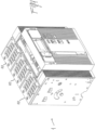
- the low voltage power circuit breaker of the present invention designated by the reference numeral 1, in its more general definition, comprises one or more electrical poles 10.
- a pole of an air insulated switch is shown for exemplary purposes.
- the present invention is of more general applicability and can be used also in other kind of switches, such as molded case circuit breakers (MCCB) or low voltage switching device in which the arching phenomena need to be taken into account.
- MCCB molded case circuit breakers
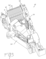
- a typical pole 10 of the circuit breaker 1 has an internal space delimited by an enclosure which, in the embodiment shown, is made of two half-enclosures coupled to each other.
- a contact area 11 and an arc extinguishing area 12 located proximate to said contact area 11.
- a fixed contact assembly 21 and a movable contact assembly 22 are respectively positioned in said contact area 11, said movable contact assembly 22 being movable between a closed position in which it is into contact with said fixed contact assembly 21 and an open position in which it is spaced apart from said fixed contact assembly 21.
- the arc chamber 30 typically comprises a plurality of substantially parallel arc-breaking plates 31 made of a ferromagnetic material which are positioned in said arc extinguishing area 12.
- said arc chamber 30 further comprises at least one arc-breaking plate 32 which is at least partially made of a ceramic material.
- the number of arc-breaking plates 32 comprising a ceramic material used in the arc chamber 30 can be selected according to the needs and cost/performance consideration, being possible to use in the arc chamber 30 only one (or a limited number) of such plates or a plurality of them.
- the invention uses one or more arc-breaking plates which comprise portions made of a ceramic material and portions made of a ferromagnetic material.
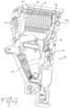
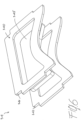
- the arc-breaking plates 32, 33, 34, 35 at least partially made of a ceramic material have a peripheral region 330, 340, 350 which is made of a ferromagnetic material and a central region 335, 345, 355 which is made of a ceramic material.
- the one or more arc-breaking plates 32, 33, 34, 35 at least partially made of a ceramic material are conveniently concentrated in a zone of said arc extinguishing area 12 which is proximate to said fixed contact assembly 21.
- the plates positioned in such zone are those subjected for more time to the arc effect and it is therefore preferable to have a relatively high number of arc-breaking plates 32, 33, 34, 35 comprising a ceramic material in a zone close to the fixed contact and the corresponding arc runner.
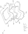
- the arc-breaking plates 33, 34, 35 which are at least partially made of a ceramic material comprise a frame 330, 340, 350 made of a ferromagnetic material and a core 335, 345, 355 made of a ceramic material.
- the core 335, 345, 355 of ceramic material is fitted inside said frame 330, 340, 350 of ferromagnetic material so as to match its internal profile, thereby obtaining a mechanically stable assembly.
- the mechanical stability of the mixed plate assembly (i.e. frame made of a ferromagnetic material, core made of a ceramic material) can be further improved by providing, as shown in figure 5 , the core 335 with one or more tabs 336, 337 engaging corresponding recesses 338, 339 formed in the internal profile of the frame 330 made of a ferromagnetic material.
- the shape and dimensioning of the frames 330, 340, 350 as well as of the cores 335, 345, 355, 81, 82, 83, 84, 85 can be designed according to the needs.
- such cores preferably have a certain thickness which can be greater than the thickness of the corresponding frames 330, 340, 350.
- said at least one arc-breaking plate 33, 34, 35 which is at least partially made of a ceramic material comprises a core 335, 345, 355 made of a ceramic material which is fitted inside a first 331, 341, 351 and a second 332, 342, 352 adjacent frames made of a ferromagnetic material so as to match the internal profiles of said first 331, 341, 351 and second 332, 342, 352 adjacent frames made of a ferromagnetic material.
- the core 335, 345, 355 of ceramic material is thicker than the frame of metallic material and is fitted inside two superimposed 331-332; 341-342; 351-352 adjacent, metallic frames.
- said arc chamber 30 advantageously comprises a plurality of substantially parallel plates 31 which are made of a ferromagnetic material and one or more arc-breaking plate 32, 33, 34, 35 which are at least partially made of a ceramic material.
- the assembly of the metallic plates 31 and ceramic-containing plates 32, 33, 34, 35 is inserted into an enclosure 60 which is made of insulating material, said enclosure 60 being in turn positioned in the arc extinguishing area 12 of the pole 10 according to known industrial embodiment.
- the particular set of the plates in the arc-breaking plates assembly allows to better withstanding the electrical and magnetic effects arising during the formation of an electrical arc in the arc chambers and at the same time to guarantee better insulation and reduce ablation of the solid surfaces with respect to the arc chambers of known type.
Landscapes
- Arc-Extinguishing Devices That Are Switches (AREA)
Claims (9)
- Niedrigspannungs-Leistungsschalter (1), der einen oder mehrere elektrische Pole (10) umfasst, wobei jeder der Pole (10) einen Innenraum mit einem Kontaktbereich (11) und einem Lichtbogenlöschbereich (12) besitzt, wobei in dem Kontaktbereich (11) eine feste Kontaktanordnung (21) und eine bewegliche Kontaktanordnung (22) angeordnet sind, wobei die bewegliche Kontaktanordnung (22) zwischen einer geschlossenen Stellung, in der sie mit der festen Kontaktanordnung (21) in Kontakt ist, und einer geöffneten Stellung, in der sie von der festen Kontaktanordnung (21) beabstandet ist, beweglich ist, wobei in dem Lichtbogenlöschbereich (12) eine Lichtbogenkammer (30) mit mehreren im Wesentlichen parallelen Lichtbogenunterbrechungsplatten (31), die aus einem ferromagnetischen Material hergestellt sind, angeordnet ist, wobei die Lichtbogenkammer (30) ferner wenigstens eine Lichtbogenunterbrechungsplatte (32, 33, 34, 35) enthält, die wenigstens teilweise aus einem keramischen Material hergestellt ist, dadurch gekennzeichnet, dass die wenigstens eine Lichtbogenunterbrechungsplatte (32, 33, 34, 35) ein umgebendes Gebiet (330, 340, 350), das aus einem ferromagnetischen Material hergestellt ist, und ein zentrales Gebiet (335, 345, 355), das aus einem keramischen Material hergestellt ist, aufweist.
- Niedrigspannungs-Leistungsschalter (1) nach Anspruch 1, dadurch gekennzeichnet, dass die Lichtbogenkammer (30) mehrere Lichtbogenunterbrechungsplatten (32, 33, 34, 35), die wenigstens teilweise aus einem keramischen Material hergestellt sind, enthält.
- Niedrigspannungs-Leistungsschalter (1) nach einem oder mehreren der vorhergehenden Ansprüche, dadurch gekennzeichnet, dass die Lichtbogenkammer (30) ferner wenigstens eine Lichtbogenunterbrechungsplatte, die vollständig aus einem keramischen Material hergestellt ist, enthält.
- Niedrigspannungs-Leistungsschalter (1) nach einem oder mehreren der vorhergehenden Ansprüche, dadurch gekennzeichnet, dass die wenigstens eine Lichtbogenunterbrechungsplatte (32, 33, 34, 35), die wenigstens teilweise aus einem keramischen Material hergestellt ist, in einer Zone des Lichtbogenlöschbereichs (12) in der Nähe der festen Kontaktanordnung (21) angeordnet ist.
- Niedrigspannungs-Leistungsschalter (1) nach einem oder mehreren der vorhergehenden Ansprüche, gekennzeichnet durch mehrere Lichtbogenunterbrechungsplatten (32, 33, 34, 35), die wenigstens teilweise aus einem keramischen Material hergestellt sind und in einer Zone des Lichtbogenlöschbereichs (12) in der Nähe der festen Kontaktanordnung (21) angeordnet sind.
- Niedrigspannungs-Leistungsschalter (1) nach einem oder mehreren der vorhergehenden Ansprüche, dadurch gekennzeichnet, dass die wenigstens eine Lichtbogenunterbrechungsplatte (32, 33, 34, 35), die wenigstens teilweise aus einem keramischen Material hergestellt ist, einen Rahmen (330, 340, 350), der aus einem ferromagnetischen Material hergestellt ist, und einen Kern (335, 345, 355, 81, 82, 83, 84, 85), der aus einem keramischen Material hergestellt ist, umfasst, wobei der Kern (335, 345, 355, 81, 82, 83, 84, 85) aus keramischem Material in den Rahmen (330, 340, 350) aus ferromagnetischem Material so eingepasst ist, dass er mit dessen innerem Profil übereinstimmt.
- Niedrigspannungs-Leistungsschalter (1) nach Anspruch 6, dadurch gekennzeichnet, dass der Kern (335, 81, 82, 83, 84, 85), der aus einem keramischen Material hergestellt ist, mit einer oder mehreren Laschen (336, 337) versehen ist, die mit entsprechenden Aussparungen (338, 339), die in dem inneren Profil des aus einem ferromagnetischen Material hergestellten Rahmens (330, 340, 350) ausgebildet sind, in Eingriff sind.
- Niedrigspannungs-Leistungsschalter (1) nach Anspruch 6 oder 7, dadurch gekennzeichnet, dass die wenigstens eine Lichtbogenunterbrechungsplatte (33, 34, 35), die wenigstens teilweise aus einem keramischen Material hergestellt ist, einen Kern (335, 345, 355) umfasst, der aus einem keramischen Material hergestellt ist und in einen ersten (331, 341, 351) und einen benachbarten zweiten (332, 342, 352) Rahmen, die aus einem ferromagnetischen Material hergestellt sind, so eingepasst ist, dass er mit den Innenprofilen des ersten (331, 341, 351) und des benachbarten zweiten (332, 342, 352) Rahmens, die aus einem ferromagnetischen Material hergestellt sind, übereinstimmt.
- Niedrigspannungs-Leistungsschalter (1) nach einem oder mehreren der vorhergehenden Ansprüche, dadurch gekennzeichnet, dass die Lichtbogenkammer (30) mehrere im Wesentlichen parallele Platten (31), die aus einem ferromagnetischen Material hergestellt sind, und wenigstens eine Lichtbogenunterbrechungsplatte (32, 33, 34, 35), die wenigstens teilweise aus einem keramischen Material hergestellt ist und in eine Umschließung (60) eingesetzt ist, die aus einem Isoliermaterial hergestellt ist und in dem Lichtbogenlöschbereich (12) angeordnet ist, enthält.
Priority Applications (3)
| Application Number | Priority Date | Filing Date | Title |
|---|---|---|---|
| EP18168308.7A EP3557599B1 (de) | 2018-04-19 | 2018-04-19 | Niederspannungsschutzschalter |
| US16/385,416 US11404225B2 (en) | 2018-04-19 | 2019-04-16 | Low-voltage circuit breaker |
| CN201910315310.5A CN110391117B (zh) | 2018-04-19 | 2019-04-19 | 低压断路器 |
Applications Claiming Priority (1)
| Application Number | Priority Date | Filing Date | Title |
|---|---|---|---|
| EP18168308.7A EP3557599B1 (de) | 2018-04-19 | 2018-04-19 | Niederspannungsschutzschalter |
Publications (3)
| Publication Number | Publication Date |
|---|---|
| EP3557599A1 EP3557599A1 (de) | 2019-10-23 |
| EP3557599C0 EP3557599C0 (de) | 2024-01-10 |
| EP3557599B1 true EP3557599B1 (de) | 2024-01-10 |
Family
ID=62027898
Family Applications (1)
| Application Number | Title | Priority Date | Filing Date |
|---|---|---|---|
| EP18168308.7A Active EP3557599B1 (de) | 2018-04-19 | 2018-04-19 | Niederspannungsschutzschalter |
Country Status (3)
| Country | Link |
|---|---|
| US (1) | US11404225B2 (de) |
| EP (1) | EP3557599B1 (de) |
| CN (1) | CN110391117B (de) |
Families Citing this family (4)
| Publication number | Priority date | Publication date | Assignee | Title |
|---|---|---|---|---|
| KR102542380B1 (ko) * | 2020-03-13 | 2023-06-12 | 엘에스일렉트릭(주) | 아크 소호부 및 이를 포함하는 기중 차단기 |
| KR102666105B1 (ko) * | 2021-05-11 | 2024-05-16 | 엘에스일렉트릭(주) | 차단부 및 이를 포함하는 기중 차단기 |
| EP4336531B1 (de) | 2022-09-06 | 2026-04-08 | ABB S.p.A. | Niederspannungsschaltpol mit einem lichtbogenunterbrechungselement mit einer abdeckung für heisse gase mit einem plattenelement und einem durchbruch |
| CN117497379A (zh) * | 2023-11-24 | 2024-02-02 | 贵州电网有限责任公司 | 一种分布式光伏测端用低压智能断路器及使用方法 |
Citations (1)
| Publication number | Priority date | Publication date | Assignee | Title |
|---|---|---|---|---|
| DE102009021022A1 (de) * | 2009-05-13 | 2010-11-18 | Siemens Aktiengesellschaft | Schutzschaltgerät, insbesondere Fehlerstromschutzschalter oder Leitungsschutzschalter |
Family Cites Families (18)
| Publication number | Priority date | Publication date | Assignee | Title |
|---|---|---|---|---|
| US2623139A (en) * | 1950-08-05 | 1952-12-23 | Allis Chalmers Mfg Co | Arc chute with trap for products of arcing |
| GB791614A (en) * | 1954-06-24 | 1958-03-05 | Ite Circuit Breaker Ltd | An electric arc extinguishing plate assembly |
| FR1223270A (fr) * | 1954-08-24 | 1960-06-16 | English Electric Co Ltd | Dispositif d'extinction d'arc pour interrupteurs électriques |
| US3641294A (en) * | 1970-01-08 | 1972-02-08 | Allis Chalmers Mfg Co | Arc chute for air circuit breaker |
| US3641293A (en) * | 1970-01-08 | 1972-02-08 | Allis Chalmers Mfg Co | Arc chute plates for air curcuit breaker |
| TW293130B (de) * | 1994-03-10 | 1996-12-11 | Mitsubishi Electric Corp | |
| US6661628B2 (en) * | 1998-12-22 | 2003-12-09 | Rockwell Automation Technologies, Inc. | Method for interrupting a current-carrying path |
| JP4419642B2 (ja) * | 2004-03-30 | 2010-02-24 | 富士電機機器制御株式会社 | 回路遮断器の消弧装置 |
| US7551050B2 (en) * | 2006-09-22 | 2009-06-23 | Rockwell Automation Technologies, Inc. | Contactor assembly with arc steering system |
| DE102008005115A1 (de) * | 2008-01-14 | 2009-07-16 | Siemens Aktiengesellschaft | Schaltgerät, insbesondere Leistungsschaltgerät, mit zwei in Reihe, geschalteten Schaltkontaktpaaren zur Unterbrechung einer Strombahn |
| CN201408683Y (zh) * | 2009-05-07 | 2010-02-17 | 上海良信电器股份有限公司 | 用于双断点小型断路器的灭弧室结构 |
| CN101847538B (zh) * | 2010-05-10 | 2012-12-19 | 刘天保 | 一种电子电磁式智能开关 |
| CN202013860U (zh) * | 2011-04-02 | 2011-10-19 | 常熟开关制造有限公司(原常熟开关厂) | 一种断路器灭弧室结构 |
| US9153399B2 (en) * | 2013-11-15 | 2015-10-06 | Eaton Corporation | ARC baffling device |
| CN203644716U (zh) * | 2013-12-26 | 2014-06-11 | 德力西电气有限公司 | 一种小型直流断路器的吹弧灭弧装置 |
| DE202015101839U1 (de) * | 2015-04-15 | 2015-04-29 | Abb Ag | Elektrisches Installationsschaltgerät mit einer Lichtbogenlöschkammer |
| CN204809069U (zh) * | 2015-06-12 | 2015-11-25 | 西安开天铁路电气股份有限公司 | 一种接触器用陶瓷迷宫式灭弧罩 |
| CN207217414U (zh) * | 2017-09-19 | 2018-04-10 | 厦门宏发电力电器有限公司 | 通过增加爬电距离提高灭弧能力的高压直流继电器 |
-
2018
- 2018-04-19 EP EP18168308.7A patent/EP3557599B1/de active Active
-
2019
- 2019-04-16 US US16/385,416 patent/US11404225B2/en active Active
- 2019-04-19 CN CN201910315310.5A patent/CN110391117B/zh active Active
Patent Citations (1)
| Publication number | Priority date | Publication date | Assignee | Title |
|---|---|---|---|---|
| DE102009021022A1 (de) * | 2009-05-13 | 2010-11-18 | Siemens Aktiengesellschaft | Schutzschaltgerät, insbesondere Fehlerstromschutzschalter oder Leitungsschutzschalter |
Also Published As
| Publication number | Publication date |
|---|---|
| EP3557599C0 (de) | 2024-01-10 |
| CN110391117B (zh) | 2023-06-20 |
| US11404225B2 (en) | 2022-08-02 |
| EP3557599A1 (de) | 2019-10-23 |
| CN110391117A (zh) | 2019-10-29 |
| US20190326072A1 (en) | 2019-10-24 |
Similar Documents
| Publication | Publication Date | Title |
|---|---|---|
| US11404225B2 (en) | Low-voltage circuit breaker | |
| EP3048625B1 (de) | Niederspannungsschaltpol | |
| EP2777058B1 (de) | Elektrisches schaltgerät mit magnetanordnung und einer ersten und zweiten löschkammer | |
| KR20180048151A (ko) | 직류용 기중차단기의 아크소호장치 | |
| WO2013171903A1 (ja) | 直流回路用回路遮断器及び直流回路用回路遮断装置 | |
| CN114551131A (zh) | 直流电灭弧装置和电机式直流电开关设备 | |
| ITMI992762A1 (it) | Camera d'arco per interruttori di bassa tensione | |
| US11837427B2 (en) | Arc chamber for a low-voltage switching device | |
| ITMI20011326A1 (it) | Polo interruttore miniaturizzato | |
| KR20200009391A (ko) | 배선용 차단기의 아크 소호 장치 | |
| CN112331536B (zh) | 低压开关极 | |
| US2343323A (en) | Electric switch | |
| CN220691951U (zh) | 一种热磁式塑壳断路器 | |
| KR200463716Y1 (ko) | 기중 차단기의 한류 장치 | |
| KR102788267B1 (ko) | 배선용 차단기의 아크 소호부 | |
| CN201069749Y (zh) | 直流断路器 | |
| CN108122698A (zh) | 灭弧装置和机电的保护开关设备 | |
| KR100442298B1 (ko) | 배선용 차단기의 단자커버 장치 | |
| CN113471032A (zh) | 机电的紧凑式保护开关设备 | |
| CN219203078U (zh) | 一种用于塑壳断路器的零飞弧罩 | |
| KR200224235Y1 (ko) | 배선용차단기의소호장치 | |
| CN204537893U (zh) | 控制与保护开关电器 | |
| CN214123823U (zh) | 塑壳断路器 | |
| EP4415014A1 (de) | Niederspannungsschaltpol | |
| KR101228840B1 (ko) | 배선용 차단기의 단극 차단유닛 외함 |
Legal Events
| Date | Code | Title | Description |
|---|---|---|---|
| PUAI | Public reference made under article 153(3) epc to a published international application that has entered the european phase |
Free format text: ORIGINAL CODE: 0009012 |
|
| STAA | Information on the status of an ep patent application or granted ep patent |
Free format text: STATUS: THE APPLICATION HAS BEEN PUBLISHED |
|
| AK | Designated contracting states |
Kind code of ref document: A1 Designated state(s): AL AT BE BG CH CY CZ DE DK EE ES FI FR GB GR HR HU IE IS IT LI LT LU LV MC MK MT NL NO PL PT RO RS SE SI SK SM TR |
|
| AX | Request for extension of the european patent |
Extension state: BA ME |
|
| STAA | Information on the status of an ep patent application or granted ep patent |
Free format text: STATUS: REQUEST FOR EXAMINATION WAS MADE |
|
| 17P | Request for examination filed |
Effective date: 20200423 |
|
| RBV | Designated contracting states (corrected) |
Designated state(s): AL AT BE BG CH CY CZ DE DK EE ES FI FR GB GR HR HU IE IS IT LI LT LU LV MC MK MT NL NO PL PT RO RS SE SI SK SM TR |
|
| STAA | Information on the status of an ep patent application or granted ep patent |
Free format text: STATUS: EXAMINATION IS IN PROGRESS |
|
| 17Q | First examination report despatched |
Effective date: 20211129 |
|
| GRAP | Despatch of communication of intention to grant a patent |
Free format text: ORIGINAL CODE: EPIDOSNIGR1 |
|
| STAA | Information on the status of an ep patent application or granted ep patent |
Free format text: STATUS: GRANT OF PATENT IS INTENDED |
|
| INTG | Intention to grant announced |
Effective date: 20231009 |
|
| GRAS | Grant fee paid |
Free format text: ORIGINAL CODE: EPIDOSNIGR3 |
|
| GRAA | (expected) grant |
Free format text: ORIGINAL CODE: 0009210 |
|
| STAA | Information on the status of an ep patent application or granted ep patent |
Free format text: STATUS: THE PATENT HAS BEEN GRANTED |
|
| AK | Designated contracting states |
Kind code of ref document: B1 Designated state(s): AL AT BE BG CH CY CZ DE DK EE ES FI FR GB GR HR HU IE IS IT LI LT LU LV MC MK MT NL NO PL PT RO RS SE SI SK SM TR |
|
| REG | Reference to a national code |
Ref country code: GB Ref legal event code: FG4D |
|
| REG | Reference to a national code |
Ref country code: CH Ref legal event code: EP |
|
| REG | Reference to a national code |
Ref country code: DE Ref legal event code: R096 Ref document number: 602018063885 Country of ref document: DE |
|
| REG | Reference to a national code |
Ref country code: IE Ref legal event code: FG4D |
|
| U01 | Request for unitary effect filed |
Effective date: 20240123 |
|
| U07 | Unitary effect registered |
Designated state(s): AT BE BG DE DK EE FI FR IT LT LU LV MT NL PT SE SI Effective date: 20240130 |
|
| U20 | Renewal fee for the european patent with unitary effect paid |
Year of fee payment: 7 Effective date: 20240424 |
|
| PG25 | Lapsed in a contracting state [announced via postgrant information from national office to epo] |
Ref country code: IS Free format text: LAPSE BECAUSE OF FAILURE TO SUBMIT A TRANSLATION OF THE DESCRIPTION OR TO PAY THE FEE WITHIN THE PRESCRIBED TIME-LIMIT Effective date: 20240510 |
|
| PG25 | Lapsed in a contracting state [announced via postgrant information from national office to epo] |
Ref country code: GR Free format text: LAPSE BECAUSE OF FAILURE TO SUBMIT A TRANSLATION OF THE DESCRIPTION OR TO PAY THE FEE WITHIN THE PRESCRIBED TIME-LIMIT Effective date: 20240411 |
|
| PG25 | Lapsed in a contracting state [announced via postgrant information from national office to epo] |
Ref country code: HR Free format text: LAPSE BECAUSE OF FAILURE TO SUBMIT A TRANSLATION OF THE DESCRIPTION OR TO PAY THE FEE WITHIN THE PRESCRIBED TIME-LIMIT Effective date: 20240110 Ref country code: RS Free format text: LAPSE BECAUSE OF FAILURE TO SUBMIT A TRANSLATION OF THE DESCRIPTION OR TO PAY THE FEE WITHIN THE PRESCRIBED TIME-LIMIT Effective date: 20240410 |
|
| PG25 | Lapsed in a contracting state [announced via postgrant information from national office to epo] |
Ref country code: ES Free format text: LAPSE BECAUSE OF FAILURE TO SUBMIT A TRANSLATION OF THE DESCRIPTION OR TO PAY THE FEE WITHIN THE PRESCRIBED TIME-LIMIT Effective date: 20240110 |
|
| PG25 | Lapsed in a contracting state [announced via postgrant information from national office to epo] |
Ref country code: RS Free format text: LAPSE BECAUSE OF FAILURE TO SUBMIT A TRANSLATION OF THE DESCRIPTION OR TO PAY THE FEE WITHIN THE PRESCRIBED TIME-LIMIT Effective date: 20240410 Ref country code: NO Free format text: LAPSE BECAUSE OF FAILURE TO SUBMIT A TRANSLATION OF THE DESCRIPTION OR TO PAY THE FEE WITHIN THE PRESCRIBED TIME-LIMIT Effective date: 20240410 Ref country code: IS Free format text: LAPSE BECAUSE OF FAILURE TO SUBMIT A TRANSLATION OF THE DESCRIPTION OR TO PAY THE FEE WITHIN THE PRESCRIBED TIME-LIMIT Effective date: 20240510 Ref country code: HR Free format text: LAPSE BECAUSE OF FAILURE TO SUBMIT A TRANSLATION OF THE DESCRIPTION OR TO PAY THE FEE WITHIN THE PRESCRIBED TIME-LIMIT Effective date: 20240110 Ref country code: GR Free format text: LAPSE BECAUSE OF FAILURE TO SUBMIT A TRANSLATION OF THE DESCRIPTION OR TO PAY THE FEE WITHIN THE PRESCRIBED TIME-LIMIT Effective date: 20240411 Ref country code: ES Free format text: LAPSE BECAUSE OF FAILURE TO SUBMIT A TRANSLATION OF THE DESCRIPTION OR TO PAY THE FEE WITHIN THE PRESCRIBED TIME-LIMIT Effective date: 20240110 |
|
| PG25 | Lapsed in a contracting state [announced via postgrant information from national office to epo] |
Ref country code: PL Free format text: LAPSE BECAUSE OF FAILURE TO SUBMIT A TRANSLATION OF THE DESCRIPTION OR TO PAY THE FEE WITHIN THE PRESCRIBED TIME-LIMIT Effective date: 20240110 |
|
| PG25 | Lapsed in a contracting state [announced via postgrant information from national office to epo] |
Ref country code: PL Free format text: LAPSE BECAUSE OF FAILURE TO SUBMIT A TRANSLATION OF THE DESCRIPTION OR TO PAY THE FEE WITHIN THE PRESCRIBED TIME-LIMIT Effective date: 20240110 |
|
| REG | Reference to a national code |
Ref country code: DE Ref legal event code: R097 Ref document number: 602018063885 Country of ref document: DE |
|
| PG25 | Lapsed in a contracting state [announced via postgrant information from national office to epo] |
Ref country code: SM Free format text: LAPSE BECAUSE OF FAILURE TO SUBMIT A TRANSLATION OF THE DESCRIPTION OR TO PAY THE FEE WITHIN THE PRESCRIBED TIME-LIMIT Effective date: 20240110 |
|
| PG25 | Lapsed in a contracting state [announced via postgrant information from national office to epo] |
Ref country code: CZ Free format text: LAPSE BECAUSE OF FAILURE TO SUBMIT A TRANSLATION OF THE DESCRIPTION OR TO PAY THE FEE WITHIN THE PRESCRIBED TIME-LIMIT Effective date: 20240110 |
|
| PG25 | Lapsed in a contracting state [announced via postgrant information from national office to epo] |
Ref country code: SK Free format text: LAPSE BECAUSE OF FAILURE TO SUBMIT A TRANSLATION OF THE DESCRIPTION OR TO PAY THE FEE WITHIN THE PRESCRIBED TIME-LIMIT Effective date: 20240110 |
|
| PG25 | Lapsed in a contracting state [announced via postgrant information from national office to epo] |
Ref country code: SM Free format text: LAPSE BECAUSE OF FAILURE TO SUBMIT A TRANSLATION OF THE DESCRIPTION OR TO PAY THE FEE WITHIN THE PRESCRIBED TIME-LIMIT Effective date: 20240110 Ref country code: SK Free format text: LAPSE BECAUSE OF FAILURE TO SUBMIT A TRANSLATION OF THE DESCRIPTION OR TO PAY THE FEE WITHIN THE PRESCRIBED TIME-LIMIT Effective date: 20240110 Ref country code: RO Free format text: LAPSE BECAUSE OF FAILURE TO SUBMIT A TRANSLATION OF THE DESCRIPTION OR TO PAY THE FEE WITHIN THE PRESCRIBED TIME-LIMIT Effective date: 20240110 Ref country code: CZ Free format text: LAPSE BECAUSE OF FAILURE TO SUBMIT A TRANSLATION OF THE DESCRIPTION OR TO PAY THE FEE WITHIN THE PRESCRIBED TIME-LIMIT Effective date: 20240110 |
|
| PLBE | No opposition filed within time limit |
Free format text: ORIGINAL CODE: 0009261 |
|
| STAA | Information on the status of an ep patent application or granted ep patent |
Free format text: STATUS: NO OPPOSITION FILED WITHIN TIME LIMIT |
|
| PG25 | Lapsed in a contracting state [announced via postgrant information from national office to epo] |
Ref country code: MC Free format text: LAPSE BECAUSE OF FAILURE TO SUBMIT A TRANSLATION OF THE DESCRIPTION OR TO PAY THE FEE WITHIN THE PRESCRIBED TIME-LIMIT Effective date: 20240110 |
|
| PG25 | Lapsed in a contracting state [announced via postgrant information from national office to epo] |
Ref country code: MC Free format text: LAPSE BECAUSE OF FAILURE TO SUBMIT A TRANSLATION OF THE DESCRIPTION OR TO PAY THE FEE WITHIN THE PRESCRIBED TIME-LIMIT Effective date: 20240110 |
|
| REG | Reference to a national code |
Ref country code: CH Ref legal event code: PL |
|
| 26N | No opposition filed |
Effective date: 20241011 |
|
| GBPC | Gb: european patent ceased through non-payment of renewal fee |
Effective date: 20240419 |
|
| PG25 | Lapsed in a contracting state [announced via postgrant information from national office to epo] |
Ref country code: GB Free format text: LAPSE BECAUSE OF NON-PAYMENT OF DUE FEES Effective date: 20240419 |
|
| PG25 | Lapsed in a contracting state [announced via postgrant information from national office to epo] |
Ref country code: GB Free format text: LAPSE BECAUSE OF NON-PAYMENT OF DUE FEES Effective date: 20240419 Ref country code: CH Free format text: LAPSE BECAUSE OF NON-PAYMENT OF DUE FEES Effective date: 20240430 |
|
| PG25 | Lapsed in a contracting state [announced via postgrant information from national office to epo] |
Ref country code: IE Free format text: LAPSE BECAUSE OF NON-PAYMENT OF DUE FEES Effective date: 20240419 |
|
| U20 | Renewal fee for the european patent with unitary effect paid |
Year of fee payment: 8 Effective date: 20250425 |
|
| PG25 | Lapsed in a contracting state [announced via postgrant information from national office to epo] |
Ref country code: CY Free format text: LAPSE BECAUSE OF FAILURE TO SUBMIT A TRANSLATION OF THE DESCRIPTION OR TO PAY THE FEE WITHIN THE PRESCRIBED TIME-LIMIT; INVALID AB INITIO Effective date: 20180419 |
|
| PG25 | Lapsed in a contracting state [announced via postgrant information from national office to epo] |
Ref country code: HU Free format text: LAPSE BECAUSE OF FAILURE TO SUBMIT A TRANSLATION OF THE DESCRIPTION OR TO PAY THE FEE WITHIN THE PRESCRIBED TIME-LIMIT; INVALID AB INITIO Effective date: 20180419 |