EP3557528B1 - System und verfahren zur analyse von testvorrichtungen - Google Patents
System und verfahren zur analyse von testvorrichtungen Download PDFInfo
- Publication number
- EP3557528B1 EP3557528B1 EP19169463.7A EP19169463A EP3557528B1 EP 3557528 B1 EP3557528 B1 EP 3557528B1 EP 19169463 A EP19169463 A EP 19169463A EP 3557528 B1 EP3557528 B1 EP 3557528B1
- Authority
- EP
- European Patent Office
- Prior art keywords
- image
- test
- test device
- analysis
- images
- Prior art date
- Legal status (The legal status is an assumption and is not a legal conclusion. Google has not performed a legal analysis and makes no representation as to the accuracy of the status listed.)
- Active
Links
Images

Classifications
-
- G—PHYSICS
- G06—COMPUTING OR CALCULATING; COUNTING
- G06T—IMAGE DATA PROCESSING OR GENERATION, IN GENERAL
- G06T7/00—Image analysis
- G06T7/30—Determination of transform parameters for the alignment of images, i.e. image registration
- G06T7/33—Determination of transform parameters for the alignment of images, i.e. image registration using feature-based methods
-
- G—PHYSICS
- G06—COMPUTING OR CALCULATING; COUNTING
- G06T—IMAGE DATA PROCESSING OR GENERATION, IN GENERAL
- G06T7/00—Image analysis
- G06T7/0002—Inspection of images, e.g. flaw detection
-
- C—CHEMISTRY; METALLURGY
- C12—BIOCHEMISTRY; BEER; SPIRITS; WINE; VINEGAR; MICROBIOLOGY; ENZYMOLOGY; MUTATION OR GENETIC ENGINEERING
- C12M—APPARATUS FOR ENZYMOLOGY OR MICROBIOLOGY; APPARATUS FOR CULTURING MICROORGANISMS FOR PRODUCING BIOMASS, FOR GROWING CELLS OR FOR OBTAINING FERMENTATION OR METABOLIC PRODUCTS, i.e. BIOREACTORS OR FERMENTERS
- C12M41/00—Means for regulation, monitoring, measurement or control, e.g. flow regulation
- C12M41/30—Means for regulation, monitoring, measurement or control, e.g. flow regulation of concentration
- C12M41/36—Means for regulation, monitoring, measurement or control, e.g. flow regulation of concentration of biomass, e.g. colony counters or by turbidity measurements
-
- G—PHYSICS
- G06—COMPUTING OR CALCULATING; COUNTING
- G06F—ELECTRIC DIGITAL DATA PROCESSING
- G06F9/00—Arrangements for program control, e.g. control units
- G06F9/06—Arrangements for program control, e.g. control units using stored programs, i.e. using an internal store of processing equipment to receive or retain programs
- G06F9/46—Multiprogramming arrangements
- G06F9/54—Interprogram communication
- G06F9/542—Event management; Broadcasting; Multicasting; Notifications
-
- G—PHYSICS
- G06—COMPUTING OR CALCULATING; COUNTING
- G06T—IMAGE DATA PROCESSING OR GENERATION, IN GENERAL
- G06T5/00—Image enhancement or restoration
- G06T5/80—Geometric correction
-
- G—PHYSICS
- G06—COMPUTING OR CALCULATING; COUNTING
- G06T—IMAGE DATA PROCESSING OR GENERATION, IN GENERAL
- G06T7/00—Image analysis
- G06T7/60—Analysis of geometric attributes
- G06T7/62—Analysis of geometric attributes of area, perimeter, diameter or volume
-
- G—PHYSICS
- G01—MEASURING; TESTING
- G01N—INVESTIGATING OR ANALYSING MATERIALS BY DETERMINING THEIR CHEMICAL OR PHYSICAL PROPERTIES
- G01N21/00—Investigating or analysing materials by the use of optical means, i.e. using sub-millimetre waves, infrared, visible or ultraviolet light
- G01N21/75—Systems in which material is subjected to a chemical reaction, the progress or the result of the reaction being investigated
- G01N21/77—Systems in which material is subjected to a chemical reaction, the progress or the result of the reaction being investigated by observing the effect on a chemical indicator
- G01N21/78—Systems in which material is subjected to a chemical reaction, the progress or the result of the reaction being investigated by observing the effect on a chemical indicator producing a change of colour
-
- G—PHYSICS
- G06—COMPUTING OR CALCULATING; COUNTING
- G06F—ELECTRIC DIGITAL DATA PROCESSING
- G06F2218/00—Aspects of pattern recognition specially adapted for signal processing
- G06F2218/12—Classification; Matching
-
- G—PHYSICS
- G06—COMPUTING OR CALCULATING; COUNTING
- G06T—IMAGE DATA PROCESSING OR GENERATION, IN GENERAL
- G06T2201/00—General purpose image data processing
- G06T2201/005—Image watermarking
- G06T2201/0051—Embedding of the watermark in the spatial domain
-
- G—PHYSICS
- G06—COMPUTING OR CALCULATING; COUNTING
- G06T—IMAGE DATA PROCESSING OR GENERATION, IN GENERAL
- G06T2207/00—Indexing scheme for image analysis or image enhancement
- G06T2207/10—Image acquisition modality
- G06T2207/10004—Still image; Photographic image
- G06T2207/10008—Still image; Photographic image from scanner, fax or copier
Definitions
- the present invention relates to a system and a method for analyzing test devices, in particular biological or chemical tests.
- the present invention can be applied to test devices comprising biological growth media receiving, for example, food samples, samples of water resources, treated water or waste, fuels or even environmental, laboratory or hospital samples. After incubation, colonies of microorganisms grow on the growth medium. These colonies are counted and classified. Once the number and types of colonies have been determined, it is possible to establish a diagnosis, which can then be used to, for example, apply corrective measures aimed at improving biosecurity, production yields or the quality of products. It is noted here that biological contamination testing has become very important and mandatory in many fields.
- test results may be used to improve and increase the repeatability, reliability, and traceability of test analysis.
- a sample for example liquid
- a biological growth medium of a test device can be placed on a biological growth medium of a test device, the test device then being inserted into an incubation chamber and then, after incubation, introduced in a scanner to analyze colony growth and count them automatically, reducing misinterpretations.
- the patent application WO 2014/080212 describes an example of reactive strips as well as a method and a reading device making it possible to carry out analyzes based on images of the strips.
- the patent application WO 2016/172527 relates to an apparatus for evaluating the evolution of colonies by image analysis, as a function of contrast, color and time.
- the picture 1 represents a test and analysis system 10 according to the teaching of the patent US 7,298,885 .
- the system 10 comprises a scanner 12, a screen 14 and a support 16 for receiving a test device 20 and introducing it into the body of the scanner 12.
- the device 20 has a test zone 22 and an identifier 24 which makes it possible to identify the device 20 (in particular determine the analysis to be performed).
- the scanner 12 can then identify the type of device 20 thanks to the identifier 24 and automatically apply an appropriate analysis.
- Screen 14 allows, for example, display test area 22, scan progress (time remaining), user-selectable options (e.g., scan parameters), and/or device 20 scan results.
- the system 10 has drawbacks, particularly in terms of cost, versatility (this system is only suitable for a specific type of device) and implementation (this system is not suitable for use in the field).
- Embodiments of the invention relate to a method of analyzing a test device as referred to in claims 1 to 5.
- the method according to the invention thus makes it possible to analyze test devices easily and at a lower cost, for example biological or chemical test devices, in particular in uncontrolled environments and/or in the absence of qualified personnel.
- the invention also relates to a computer program comprising instructions adapted to the implementation of each of the steps of the method described previously, when said program is executed on a computer.
- the advantages provided by this computer program are similar to those mentioned above.
- the invention also relates to a system for analyzing a test device comprising means adapted to the implementation of each of the steps of the method described previously.
- the advantages provided by this system are similar to those mentioned with regard to the process.
- the system comprises an image capture, image correction and image analysis device of the smartphone type.
- the system comprises a first image capture device and a second image analysis device, separate from the first device.
- the invention relates to a system and a method for analyzing test devices, in particular biological or chemical tests, allowing for example the detection, counting and/or classification of colonies of microorganisms, using a common visual reference to identify the device (preferably allowing selection of a type of analysis to be performed) and to analyze the device by image analysis, without requiring a particular point of view when taking images of the device.
- Embodiments of the invention are suitable for observing the growth of colonies of microorganisms in order to analyze their evolution over time.
- an analysis unit such as an intelligent telephone (smartphone) or a tablet equipped with an image sensor, comprising a suitable software application, can be used to capture an image of the device, the captured images can be processed and analyzed either by the analysis unit itself (if it has the necessary resources) or, for example, by a remote server to which the images or parts of images are transferred.
- the analysis unit can consist of a simple digital camera device.
- the analysis method is implemented in the analysis unit, with the aid of a suitable application, which is used for the capture of images, the normalization of the images acquired and their analysis.
- a suitable application which is used for the capture of images, the normalization of the images acquired and their analysis.
- the user can also be guided in the use of the application, for example to indicate the instants at which images must be taken.
- test device is now described in more detail.
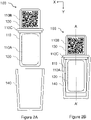
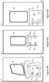
- the figures 2A and 2B represent front views of the same test device 100 that can be used by an analysis system, according to embodiments, in two different configurations.
- the embodiments of the invention described below relate to a device for the biological growth of colonies of microorganisms.
- the invention is not limited to this field.
- the test device 100 can take an open configuration, as illustrated in the figure 2A or a closed configuration as shown in the figure 2B .
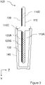
- the picture 3 shows a sectional view, in profile, of the test device 100 illustrated in the figures 2A and 2B , in the configuration of the figure 2B .
- the test device 100 comprises a support 110, a test area 120, a visual reference 130 and a protective cover 140.
- the visual reference 130 allows identification of the test device 100 and normalization of an image representing this device, typically by determining a geometric deformation of a representation of the test zone as a function of a predetermined format of the visual reference.
- the support 110 comprises a first part 110A, called the lower part, and a second part 110B, called the upper part, separated by a closure stop 110C.
- the lower part 110A comprises the test area 120. It is configured to be able to be inserted into the protective envelope 140, as shown in the figure 2B and 3 . It is observed here that the closing abutment 110C can be an added piece.
- the protective envelope 140 forms, with the support 110, a closed system enveloping and isolating the test area 120 from the external environment.
- the protective envelope 140 is ideally transparent in order to allow regular image captures during the test, without exposing the test area 120 to ambient air and, thus, to possible external contamination.
- the upper part 110B can be used for handling the test device 100 without a user touching the test zone 120 and risking contaminating it.
- the visual reference 130 is here arranged on the upper part 110B, ideally above the abutment 140 and outside the protective envelope 140 so that its reading is not disturbed.
- the test zone 120 here comprises a development medium 120A, for example a nutrient medium, and an observation surface 120B.
- the development medium 120A allows for example the development of microorganisms and/or chemical and/or biological markers making it possible to reveal the presence of biological activities of the microorganisms and/or making it possible to count and/or classify these microorganisms. organisms.
- test area 120 and the visual reference 130 are arranged on the same face of the support 110, preferably in the same XY plane (the X axis being oriented along the width of the device 100 and the axis Y being oriented along the length of the device 100) or in parallel planes.
- Viewing surface 120B preferably overlies development medium 120A which is, for example, flat and square or circular in shape.
- the development medium 120A may comprise a support such as a buffer which may consist of cellulosic derivatives to retain a liquid or a gel allowing the development of microorganisms.
- the protective envelope 140 can serve as a container to receive (preferably temporarily) a sample to be analyzed in which the test zone 120 can be immersed.
- test device 100 After test area 120 has been brought into contact with a sample to be tested and, if applicable, excess sample has been removed from test area 120, test device 100 is allowed to incubate for one some time, the test zone 120 being protected in the protective envelope 140. As described below, photographs of the device can be taken and analyzed according to the nature of the tests to be carried out.
- the visual reference 130 is, for example, a visual identifier of the QR code type (abbreviation for Quick Response code in English terminology), a barcode or another identifier having a predetermined format.
- This format can be defined, for example, by the manufacturer of the device, the developer of an image processing software according to embodiments of the invention or by an analysis laboratory which receives images from the test device .
- the visual reference 130 typically makes it possible to determine an analysis to be performed. This reference can be common to several test devices or specific to each test device.
- the identifier provided by the visual reference 130 can be used as a database entry in order to obtain and/or fill in information such as a type of microphone - organization, a manufacturer, a test protocol, a validity date, the name of a user, a date of use, etc.
- This database can be initially completed by the manufacturer of the test device and then enriched when the test device is used.
- Several databases, corresponding to several test devices and/or to several types of information, can be used.
- the visual reference 130 also makes it possible to normalize, if necessary, an image representing the test device by adapting, for example, the scale factor and/or the perspective. For these purposes, the visual reference 130 is used as a reference to determine a deformation or to define such a reference.
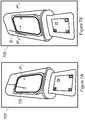
- FIGS. 4A, 4B, 4C and 4D illustrate successive observations of the same test device during tests.
- the figure 4A illustrates the test device 100 at a time to, for example just after the test zone 120 of the device 100 has been brought into contact with the sample to be analyzed.
- a task denoted O 1 (t 0 ) is observed on the observation surface 120B at time t 0 .
- the characteristics of this spot for example its position, its size, its color and its shape, are preferably recorded in order to make it possible to analyze its evolution.
- the figure 4B illustrates the same test device 100 at a time t 1 , for example 24 hours after time to. Again, the characteristics of the observed spots, for example its position, size, color and shape, can be recorded. According to the example shown in the figure 4B , task O 1 has not evolved between times t 0 and t 1 (ie tasks O 1 (t 0 ) and O 1 ( t 1 ) are equivalent) and task O 2 has appeared on the surface of observation 120B.
- the observation surface 120B shows, at a time t 2 , for example 48 hours after time t 0 , the spots O 1 and O 2 already observed previously and a new spot O 3 .
- the size of the spot O 2 has increased here compared to the observation made at time t 1 .
- the characteristics of the observed spots for example its position, size, color and shape, are recorded here.
- the 4D figure illustrates the same device 100 at a time t 3 , for example 72 hours after time to.
- no new task has appeared and the size of tasks O 2 and O 3 has increased compared to the observation made at time t 2 , the size of task O 3 having increased more rapidly than that of task O 2 .
- the characteristics of the observed spots for example its position, size, color and shape, are preferably recorded.
- the characteristics of task O 1 have not changed between times to to t 3 . It can therefore be concluded that the task O 1 is not representative of a colony of microorganisms. It may be, for example, a dust. Furthermore, it can be considered that the O 2 spot represents a colony of slowly growing microorganisms (under the test conditions) and that the O 3 spot represents a colony of fast growing microorganisms (still under the test conditions). testing).
- colonies of microorganisms appear in “waves” of time if there are subpopulations in the sample being tested. If the image captures are frequent enough, the detection of such waves can be an indication of the number of subpopulations, it being observed that it takes about a million microorganisms for a colony to be observable to the eye. bare but only a few thousand microorganisms can usually be detected by a x10 magnification (often offered by the image sensors of a smartphone or tablet).
- the rate at which the size of a colony grows is an indication of the doubling time (in the exponential phase) constituting an indication of the specific strain of the colony, it being observed that between the initial instant and the exponential phase, the bacteria generally experience a so-called latency phase during which they adapt to their new environment and do not multiply or only slightly.
- Colonies are generally round but may be truncate, overlap, or have different shapes (irregular, filamentous, rhizoid, etc.) depending on the type of colony.
- the color of a colony is usually white but can be transparent, eggshell colored, or otherwise.
- nutrient media can generate distinct colony colors or halos around colonies. These aspects are well known in the art.
- the analysis of an image can then include the evaluation of the shape, the color, the border, etc. Other optical techniques make it possible to observe the relief and the texture of the colonies, for example by analyzing the deformation of a known pattern projected onto and reflected by the test zone 120.
- Relief and texture information is complementary to information on size, growth rate, color, transparency and the like and increases the ability of the system to correctly classify colonies.
- the user is requested to capture the images which are then analyzed. He can thus be alerted at the start of the test of the number of images to be taken and of the instants at which the images must be taken. It can also be notified each time an image needs to be taken.
- the visual reference 130 notably allows the execution of a normalization step so that images taken from different points of view can be compared. It is thus possible to standardize the image captures by knowing the format of the visual reference 130.
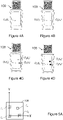
- the figure 5A , 5B and 5C illustrate a first example of normalization based on a predetermined format of a visual reference in order to allow the comparison of images of a test device obtained from several different points of view.
- the visual reference and the observation surface of the test device are arranged in the same plane.
- the figure 5A illustrates an example of a visual reference used as a geometric reference.
- the visual reference 130 used here is a QR code having a predetermined size.
- the QR code comprises three distinct squares C 1 , C 2 and C 3 , called position squares, arranged in the lower left, lower right and upper left corners, respectively, as illustrated.
- the QR code further comprises a fourth square C 4 , called an alignment square (the QR code may comprise several alignment squares depending on the version of the QR code implemented).
- the alignment square or squares make it possible to correct an image of the code with respect to the size, the orientation and the angle of image capture.
- the center of the squares of position C 1 , C 2 and C 3 is used to form a geometric reference in which can be expressed the coordinates of the points of the visual reference as well as the coordinates of the points of the observation surface of the test device (the visual reference and the observation surface being here placed in the same plane).
- the center of the square of position C 1 forms the origin of the frame
- the center of the squares of position C 1 and C 2 forms the abscissa axis as well as the unit vector along this axis
- the center of the squares of position C 1 and C 3 forms the ordinate axis as well as the unit vector along this axis.
- the figures 5B and 5C illustrate two images representing a test device 100 observed from two distinct points of view.
- the identification of the visual reference 130 and of the position squares C 1 , C 2 and C 3 makes it possible to define a geometric reference linked to visual reference 130, as described with reference to figure 5A .
- the coordinates of points on the observation surface of the analyzed test device, taken from images obtained from different observation points, for example points P and P' on the figures 5B and 5C , in this "normalized" benchmark, can be compared with each other to study, for example, the development of colonies of microorganisms.
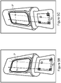
- the figures 6A, 6B and 6C illustrate a second example of normalization based on a predetermined format of a visual reference in order to allow the comparison of images of a test device obtained from several different points of view.
- the visual reference used here is similar to that shown in the figure 5A .
- the figures 6A, 6B and 6C show three images representing the same test device observed from three different viewpoints at three different times.
- standard image analysis techniques implemented, for example, to identify QR codes, can be used to identify the position and alignment squares C 1 , C 2 , C 3 and C 4 and determine the coordinates of their center, denoted ( x 1 , y 1 ) , ( x 2 , y 2 ) , (x 3 , y 3 ) and (x 4 , y 4 ), respectively, in a frame linked to the image in which these squares are identified.
- the Figure 6A represents a first image 600 of a test device obtained according to a first point of view, in which it is possible to identify the squares of position and alignment C 1 1 , C 1 2 , C 1 3 and C 1 4 and determine the coordinates of their center, denoted ( x 1 1 , y 1 1 ) , (x 1 2 , y 1 2 ), (x 1 3 , y 1 3 ) and ( x 1 4 , y 1 4 ) , respectively , in a frame linked to the image in which these squares are identified.
- the image 600 has for example been obtained at a time t 1 .
- the figure 6B represents a second image 605 of the test device obtained from a second point of view, in which it is possible to identify the position and alignment squares C 2 1 , C 2 2 , C 2 3 and C 2 4 and to determine them coordinates of their center, denoted ( x 2 1 , y 2 1 ) , (x 2 2 , y 2 2 ), (x 2 3 , y 2 3 ) and (x 2 4 , y 2 4 ), respectively, in a marker linked to the image in which these squares are identified.
- the image 605 has for example been obtained at a time t 2 .
- the Fig. 6C represents a third image 610 of the test device obtained from a third point of view, in which it is possible to identify the position and alignment squares C 3 1 , C 3 2 , C 3 3 and C 3 4 and to determine the coordinates of their center.
- the image 610 has for example been obtained at a time t 3 .
- the coordinates of a spot identified in an observation surface represented in a first image can be projected into the corresponding observation surface of a second image, for example image 605 , to allow a comparison of these coordinates with those of the corresponding spot of the observation surface represented in the second image.
- the coordinates of a spot identified in an observation surface represented in a first image can be projected into the corresponding observation surface of a third image, for example image 610, to allow a comparison of these coordinates with those of the corresponding task of the observation surface represented in the third image.
- the visual reference is used to define the points to be used to carry out the projection, these can be points distinct from the visual reference.
- the visual reference can be used to identify the observation surface of the test device if the positions of the latter and of the visual reference are predetermined.
- the figures 7A and 7B illustrate an example of image correction according to a particular embodiment, between a first image 700 and a second image 705, respectively.
- Such a correction can be carried out following the detection of a suspected defect in an image or in a sequence of images, for example when an unexpected element is detected (due, for example, to its shape, its color , its size or its evolution over time).
- the figures 7A and 7B show two images representing the same test device observed from two different viewpoints at two instants close to each other.
- the image shown on the figure 7B was taken here following the detection of a potential defect on the image represented on the Figure 7A .
- the analysis of the observation surface of the test device represented on the Figure 7A makes it possible to identify a task P 11 and to detect a potential defect DS due, for example, to its shape and its color.
- Another image is obtained from a different point of view, here the image represented on the figure 7B .
- This image is acquired as soon as possible after obtaining the image on which a potential defect is detected.
- the application can, after detecting a potential defect, alert the user and suggest that he acquire a new image to remove the doubt.
- the analysis of the observation surface of the test device represented on the figure 7B makes it possible to identify the tasks P 2 1 and P 2 2 but does not reveal any potential defect. It can therefore be deduced that the potential defect identified on the observation surface of the test device represented on the Figure 7A is a fault that can be ignored.
- an analysis of the area located around the observation surface of the test device represented on the image used to determine whether it is a defect or not can be carried out to identify the defect previously identified potential.
- the defect presented on the figure 7 is a scratch or mark on the outer surface of shroud 140. It could also be, for example, a droplet of condensation on the inner surface of shroud 140.
- the change of point of view also makes it possible to reveal, on the image of the figure 7B , the spot P 2 2 which was masked on the image of the figure 7B .
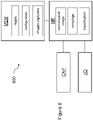
- the figure 8 shows an example of an analysis unit 800 that can be used by an analysis system according to a particular embodiment.
- the analysis unit 800 for example a smartphone, here comprises an image sensor denoted CAP, a memory denoted MEM, a microprocessor denoted MP and an input/output module denoted I/O. These various elements are here controlled by an application executed on the analysis unit.
- the CAP image sensor is capable of taking images of the test device 100 with at least a portion of the observation surface 120B and the visual reference 130 with, preferably, a resolution making it possible to analyze the observation surface. depending on the type of test to be performed.
- capturing images is performed by a user on the recommendation of the application. A captured image is then transferred to the MP microprocessor for processing.
- the MEM memory can be used to store the application as well as captured images. It can also be used to store, in the application or independently, counting, classification and defect determination rules, incubation rules and result validation rules. Alternatively, these rules can be stored in a remote system.
- the memory MEM can, for example, be updated by the end user, by a laboratory, by the software developer or by the manufacturer of the device 100.
- the microprocessor MP receives an image acquired by the image sensor CAP.
- a first test is preferably carried out to determine whether the acquired image is usable, for example whether it is sufficiently clear, whether it comprises a representation of the visual reference and at least part of the observation surface.
- the visual reference is then, preferably, analyzed, for example to access and/or verify characteristics of the test device 100, for example if it is not expired and/or if it is compatible with the conditions of the tests considered. Characteristics of the analysis unit 700 can then be obtained, for example geolocation data, a time reference (present instant), etc.
- the microprocessor MP carries out a step of normalizing an image acquired according to the visual reference.
- a step may in particular consist of the definition of a particular frame in which the coordinates of the analyzed points are expressed or in the projection of the image (or of certain points of the image) according to the visual reference and according to another picture.
- the acquired image is then analyzed, according to the determined normalization, in order, for example, to identify tasks and to compare them with tasks identified in a previous step.
- an I/O input/output module allows a user to control the analysis unit, for example to capture images, and to enter information, for example comments.
- This module also makes it possible to send notifications to the user, for example to ask him to perform actions such as capturing an image, to warn him of upcoming actions, for example to warn him that it will be appropriate to capture a new image in a time of n minutes or n hours (n being typically determined by the application according to the nature of the tests to be performed), or give him indications or information, for example indications relating to the test conditions and/or the test device.
- the I/O input/output module can also be used to exchange data with a remote system, for example a server, for example to transmit test results. Such exchanges can be predetermined and/or can be hidden from the user.
- one or more elements of the analysis unit are absent or are not used, corresponding elements of another unit being used.
- an image processing for example a projection
- it can be deported to a remote unit, for example a remote server.
- the analysis unit can then be used as an image sensor and user interface.
- the application used can provide information to the user and guide him in the tests to be carried out, for example to indicate to him how to obtain a sample and bring it into contact with the test area of the test device, what are the test conditions, for example the incubation time and temperature, to assist him in taking images, for example using alignment or lighting indications. Examples of images can also be presented to him to help him.
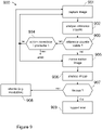
- the figure 9 illustrates steps of an exemplary analysis method according to one embodiment.
- the analysis method 900 here comprises the steps 901 to 909. It can be implemented, for example, using the system 800 illustrated in the figure 8 , for example in the form of an application.
- step 901 The purpose of step 901 is to capture an image of the test device 100.
- a notification can be sent to a user, after the latter has launched the application or has launched a new test. , so that it captures an image of the test device.
- the first captured image can be obtained before a sample is presented to the test area of the test device, for example to obtain a reference image of the test device, just after a sample is presented to the test area.
- test of the test device to have a first image of the start of the test or after a certain incubation time.
- the user can take other images, for example images representative of the test environment or of the source of the sample.
- a quality test is advantageously carried out to check the quality of the acquired image, for example its sharpness and/or the presence of a representation of at least part of the observation surface. If the quality is not sufficient, for example with regard to a predetermined criterion, the user may be asked to capture another image.
- the acquired image is stored with additional information (metadata), such as an identifier of the image, an identifier of the analysis unit used to capture the image, an identifier of the user who captured the image, an indication of the source of the sample, an indication of the temperature of the environment in which the test is taking place, geolocation information such as GPS data (abbreviation for global positioning system in terminology Anglo-Saxon) and/or an indication of the date and time of the image capture.
- metadata such as an identifier of the image, an identifier of the analysis unit used to capture the image, an identifier of the user who captured the image, an indication of the source of the sample, an indication of the temperature of the environment in which the test is taking place, geolocation information such as GPS data (abbreviation for global positioning system in terminology Anglo-Saxon) and/or an indication of the date and time of the image capture.
- a first analysis of the acquired image is carried out to identify a visual reference having a predetermined format (for example a QR code or a barcode), using a standard algorithm .
- the identifier corresponding to the visual reference can be used to obtain data associated with this identifier in one or more databases. As described above, such data are, for example, a manufacturer, a test protocol and/or a validity date.
- a link is also established between this identifier, the acquired image and, preferably, at least some of the additional information or metadata referred to above.
- the image and this additional information may in particular be stored in the database or databases described above in connection with the identifier.
- a test is then performed to determine if the visual reference is valid, for example if its format conforms to the expected format and/or if it defines an expected identifier (step 903).
- the identifier corresponding to the visual reference is valid, that is to say, for example, if it corresponds to a test device that has not expired and corresponds to the tests to be performed. It can also be verified that the test zone is well represented in the image or that there is, a priori, no artefact.
- a help message is addressed to the user to indicate to him the nature of the anomaly (eg " device expired, continue? ”) and/or to indicate the reason for the failure and help him overcome it (eg " proportion of the test area insufficient: take a new, better framed image " or “ potential artefact: taking a new image from a different angle”).
- the acquired image can be analyzed.
- the visual reference is analyzed to determine a normalization of the acquired image (step 905).
- a normalization may in particular consist in determining a “normalized” frame in which the coordinates of the points studied are expressed or in projecting the image being analyzed or a part of this image as a function of the visual frame of this image and the visual cue of a previously acquired image (of the same test device).
- step 906 the image is analyzed (step 906).
- This analysis can be carried out in an analysis unit, for example a smartphone or a tablet, or in a system, for example a remote server.
- the analysis includes the identification and characterization of features on an observation surface, typically the identification and characterization of spots by their color, shape and size.
- the analysis also comprises, preferably, for the second image acquired and the following ones, the comparison of the characteristics of the elements identified with those of the elements identified on observation surfaces of previous images.
- this analysis step includes the comparison of characteristics expressed from a common reference (or "normalized") or the comparison of characteristics linked to a first image with characteristics of a projection of a second image (or part of the second image).
- a common reference or “normalized”
- one or more previous images or characteristics obtained by analyzing these images
- This analysis makes it possible, for example, to identify colonies of bacteria, to count them and to compare them between successive images.
- a test is carried out to determine whether or not the tests are finished, that is to say whether or not other images must be acquired and analyzed.
- the end of the test can be predetermined, for example according to a time scale, or linked to an observation, for example a number of colonies detected.
- step 907 the previous steps (steps 901 to 907) are repeated to process a new image. These steps are repeated after a predetermined time (step 908), for example an incubation time.
- test report is preferably generated (step 909). It contains, for example, statistics relating to the elements identified, their characteristics and their evolution.
- the analysis of an observation surface represented in an image can begin after the capture of the latter, without waiting for the identification of the test device.
- image analysis may be performed after a large number of images, or all images have been acquired. It is also possible to analyze one image while capturing another image.
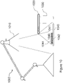
- the figure 10 represents an example of an analysis system 1000 according to a particular embodiment.
- System 1000 is particularly suitable for use in various environments.
- System 1000 includes an artificial light source 1010 (natural light works just as well or better than artificial light, but is not always available in sufficient quantity for a good shot) , for example a desk lamp, an analysis unit 1020, for example a smartphone, a support 1030 for the analysis unit, for example a beverage can, and a test device 1040.
- an artificial light source 1010 natural light works just as well or better than artificial light, but is not always available in sufficient quantity for a good shot
- an analysis unit 1020 for example a smartphone
- a support 1030 for the analysis unit for example a beverage can
- test device 1040 for example a test device 1040.
- the device 1040 comprises a visual reference 1041, a test area 1042 and an observation surface 1043 protected by a protective envelope 1044.
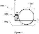
- the figure 11 shows a front view of a test device 1100 according to another embodiment.
- the test device 1100 here comprises a support 1110, a test area 1120 and a visual reference 1130.
- the visual reference 1130 is a barcode whose format can be used to define a mark in which can be expressed the coordinates of elements detected on the observation surface of the test area 1120.
- the abscissa axis is defined as the lower edge of the barcode and the ordinate axis as the left edge of the barcode, the origin of the mark being the lower left corner of the barcode (when the device is seen from the front, the test zone being placed on the right).
- test device 1100 can be used within the framework of the analysis systems and methods of analysis described previously.
Landscapes
- Engineering & Computer Science (AREA)
- Theoretical Computer Science (AREA)
- Physics & Mathematics (AREA)
- General Physics & Mathematics (AREA)
- Computer Vision & Pattern Recognition (AREA)
- Chemical & Material Sciences (AREA)
- Software Systems (AREA)
- General Engineering & Computer Science (AREA)
- Bioinformatics & Cheminformatics (AREA)
- Organic Chemistry (AREA)
- Zoology (AREA)
- Wood Science & Technology (AREA)
- Health & Medical Sciences (AREA)
- Life Sciences & Earth Sciences (AREA)
- Geometry (AREA)
- Quality & Reliability (AREA)
- Multimedia (AREA)
- Sustainable Development (AREA)
- Biomedical Technology (AREA)
- Analytical Chemistry (AREA)
- Microbiology (AREA)
- Biochemistry (AREA)
- General Health & Medical Sciences (AREA)
- Genetics & Genomics (AREA)
- Biotechnology (AREA)
- Apparatus Associated With Microorganisms And Enzymes (AREA)
- Image Processing (AREA)
- Analysing Materials By The Use Of Radiation (AREA)
Claims (9)
- Verfahren zur Analyse einer Testvorrichtung, wobei das Verfahren die folgenden Schritte umfasst:- Erhalten mindestens eines Bildes von einer Testvorrichtung (100, 1040, 1100), wobei das Bild mindestens eine Darstellung von mindestens einem Abschnitt einer Beobachtungsoberfläche (120B, 1043) und eine visuelle Referenz (130, 1041, 1030) in einem vorher festgelegten Format umfasst;- Identifizieren einer Testvorrichtung in Abhängigkeit von der visuellen Referenz;- Identifizieren mindestens eines graphischen Elements in dem mindestens einen Abschnitt der Beobachtungsoberfläche, wobei das mindestens eine graphische Element aus einem biologischen oder chemischen Test resultiert;- Bestimmen mindestens eines in Abhängigkeit von mindestens der visuellen Referenz identifizierten geometrischen Merkmals des mindestens einen graphischen Elements, wobei das mindestens eine geometrische Merkmal mindestens eine Größe oder eine Form umfasst; und- Analysieren des mindestens einen Abschnitts der Beobachtungsoberfläche in Abhängigkeit von einer Identifizierung der Testvorrichtung und von mindestens einem bestimmten geometrischen Merkmal,wobei der Schritt des Analysierens einen Schritt des Vergleichens des mindestens einen bestimmten geometrischen Merkmals mit mindestens einem geometrischen Merkmal eines graphischen Elements umfasst, das in einem Abschnitt einer Beobachtungsoberfläche identifiziert ist, der in einem anderen Bild derselben Testvorrichtung dargestellt ist.
- Verfahren nach Anspruch 1, umfassend ferner einen Schritt des Mitteilens des Erhalts eines neuen Bildes, wobei die Mitteilung in Abhängigkeit von einer ausgehend von einem zuvor erhaltenen Bild bestimmten Identifizierung der Testvorrichtung mitgeteilt wird.
- Verfahren nach Anspruch 2, wobei der Schritt des Mitteilens einen Schritt des Erhaltens einer Testinformation umfasst, wobei die Testinformation in Abhängigkeit von der ausgehend von dem zuvor erhaltenen Bild bestimmten Identifizierung der Testvorrichtung mitgeteilt wird.
- Verfahren nach einem der Ansprüche 1 bis 3, umfassend ferner einen Schritt des Speicherns des empfangenen Bildes und der ausgehend von dem erhaltenen Bild bestimmten Identifizierung der Testvorrichtung.
- Verfahren nach einem der Ansprüche 1 bis 4, wobei das mindestens eine geometrische Merkmal ferner Koordinaten umfasst.
- Rechnerprogramm, das für die Durchführung von jedem der Schritte des Verfahrens nach einem der Ansprüche 1 bis 5 geeignete Befehle umfasst, wenn das Programm auf einem Rechner ausgeführt wird.
- System zur Analyse einer Testvorrichtung, das für die Durchführung von jedem der Schritte des Verfahrens nach einem der Ansprüche 1 bis 5 geeigneten Mittel umfasst.
- System nach Anspruch 7, welches eine Bilderfassungs-, Bildkorrektur- und Bildanalysevorrichtung vom Typ Smartphone umfasst.
- System nach Anspruch 7, welches eine erste Bilderfassungsvorrichtung und eine zweite Bildanalysevorrichtung umfasst, die sich von der ersten Vorrichtung unterscheidet.
Applications Claiming Priority (1)
| Application Number | Priority Date | Filing Date | Title |
|---|---|---|---|
| FR1853321A FR3080211B1 (fr) | 2018-04-16 | 2018-04-16 | Systeme et procede d'analyse de dispositifs de test |
Publications (2)
| Publication Number | Publication Date |
|---|---|
| EP3557528A1 EP3557528A1 (de) | 2019-10-23 |
| EP3557528B1 true EP3557528B1 (de) | 2022-07-13 |
Family
ID=63143231
Family Applications (1)
| Application Number | Title | Priority Date | Filing Date |
|---|---|---|---|
| EP19169463.7A Active EP3557528B1 (de) | 2018-04-16 | 2019-04-16 | System und verfahren zur analyse von testvorrichtungen |
Country Status (3)
| Country | Link |
|---|---|
| US (1) | US11145044B2 (de) |
| EP (1) | EP3557528B1 (de) |
| FR (1) | FR3080211B1 (de) |
Citations (1)
| Publication number | Priority date | Publication date | Assignee | Title |
|---|---|---|---|---|
| US20170067832A1 (en) * | 2015-09-08 | 2017-03-09 | Xerox Corporation | Methods and devices for improved accuracy of test results |
Family Cites Families (19)
| Publication number | Priority date | Publication date | Assignee | Title |
|---|---|---|---|---|
| US5492835A (en) * | 1994-07-13 | 1996-02-20 | Gerald J. Churchill | Swab identification testing device and method |
| CA2267125C (en) * | 1996-09-30 | 2008-04-01 | California South Pacific Investors | Detection of contaminants in food |
| US6230548B1 (en) * | 1998-07-14 | 2001-05-15 | Chi-Neng Arthur Han | System for testing properties of materials |
| US7899681B2 (en) * | 2002-03-29 | 2011-03-01 | 3M Innovative Properties Company | Electronic management of sterilization process information |
| US7298885B2 (en) | 2002-11-27 | 2007-11-20 | 3M Innovative Properties Company | Biological growth plate scanner with automated image processing profile selection |
| EP2416702A2 (de) * | 2009-04-07 | 2012-02-15 | Reveal Sciences, Llc | Vorrichtung, verfahren und gerät für bologisches testen mit einer mobilen vorrichtung |
| JP5575534B2 (ja) * | 2010-04-30 | 2014-08-20 | 株式会社東芝 | 超音波診断装置 |
| US8506901B2 (en) * | 2010-11-03 | 2013-08-13 | Teco Diagnostics | All-in-one specimen cup with optically readable results |
| CN102539735A (zh) * | 2010-11-12 | 2012-07-04 | 美艾利尔圣地亚哥有限公司 | 集成质量保证标签的测试装置和系统 |
| WO2013096801A1 (en) * | 2011-12-23 | 2013-06-27 | Abbott Point Of Care Inc | Reader devices for optical and electrochemical test devices |
| US9506855B2 (en) * | 2012-02-03 | 2016-11-29 | University Of Cincinnati | Method and system for analyzing a colorimetric assay |
| CN104969068B (zh) * | 2012-08-08 | 2019-06-18 | 思勘度股份有限公司 | 用于在自动校准环境中执行及量化由特定浓度的生物分析物诱发的色彩改变的方法及设备 |
| US9528941B2 (en) * | 2012-08-08 | 2016-12-27 | Scanadu Incorporated | Method and apparatus for determining analyte concentration by quantifying and interpreting color information captured in a continuous or periodic manner |
| GB201221015D0 (en) * | 2012-11-22 | 2013-01-09 | Microlab Devices Ltd | Test strip nd methods and apparatus for reading the same |
| KR20150096718A (ko) * | 2012-12-20 | 2015-08-25 | 쓰리엠 이노베이티브 프로퍼티즈 컴파니 | 이미지 내의 미생물 콜로니를 구분하는 방법 |
| WO2016025935A2 (en) * | 2014-08-15 | 2016-02-18 | Scanadu Incorporated | Precision luxmeter methods for digital cameras to quantify colors in uncontrolled lighting environments |
| EP3286731B1 (de) * | 2015-04-23 | 2020-09-16 | BD Kiestra B.V. | Kolonienkontrasterfassung |
| EP3380825B1 (de) * | 2015-11-23 | 2020-09-23 | CellTool GmbH | Vorrichtung und verfahren zum analysieren biologischer objekte mit raman spektroskopie |
| US11915810B2 (en) * | 2016-12-14 | 2024-02-27 | Reliant Immune Diagnostics, Inc. | System and method for transmitting prescription to pharmacy using self-diagnostic test and telemedicine |
-
2018
- 2018-04-16 FR FR1853321A patent/FR3080211B1/fr active Active
-
2019
- 2019-04-15 US US16/384,439 patent/US11145044B2/en active Active
- 2019-04-16 EP EP19169463.7A patent/EP3557528B1/de active Active
Patent Citations (1)
| Publication number | Priority date | Publication date | Assignee | Title |
|---|---|---|---|---|
| US20170067832A1 (en) * | 2015-09-08 | 2017-03-09 | Xerox Corporation | Methods and devices for improved accuracy of test results |
Also Published As
| Publication number | Publication date |
|---|---|
| FR3080211B1 (fr) | 2020-05-08 |
| EP3557528A1 (de) | 2019-10-23 |
| US20190318468A1 (en) | 2019-10-17 |
| FR3080211A1 (fr) | 2019-10-18 |
| US11145044B2 (en) | 2021-10-12 |
Similar Documents
| Publication | Publication Date | Title |
|---|---|---|
| EP2661213B1 (de) | System und verfahren zur erkennung der empfindlichkeit einer person gegenüber einer oder mehreren potenziell allergenen substanzen | |
| CN113361487B (zh) | 异物检测方法、装置、设备及计算机可读存储介质 | |
| US11054370B2 (en) | Scanning devices for ascertaining attributes of tangible objects | |
| FR3081248A1 (fr) | Systeme et procede de determination d’un emplacement pour le placement d'un paquet | |
| US20200124631A1 (en) | Barcode scanning of bulk sample containers | |
| WO2016083744A1 (fr) | Procede, systeme et produit-programme d'ordinateur pour determiner la croissance de micro-organismes | |
| EP4232946B1 (de) | Verfahren zur klassifizierung einer sequenz von eingabebildern, die ein teilchen in einer probe im laufe der zeit darstellen | |
| CN111356914B (zh) | 一种检测方法和检测装置 | |
| EP3557528B1 (de) | System und verfahren zur analyse von testvorrichtungen | |
| FR2852422A1 (fr) | Procede d'identification automatique d'entites dans une image numerique | |
| WO2010092271A1 (fr) | Procédé de préparation d'une plaque d'analyse virtuelle traitée | |
| WO2015162364A1 (fr) | Procédé, système et produit-programme d'ordinateur pour afficher une image d'un objet | |
| WO2024194408A1 (fr) | Procédé et dispositif d'anatomopathologie avec identification et suivi d'objets | |
| FR3034103A1 (fr) | Procede de mesure de la concentration de microorganismes dans un liquide | |
| Esfandi et al. | Determining the efficacy of visual inspections at detecting non-biosecurity–compliant goods | |
| Szczepanski | Online stereo camera calibration on embedded systems | |
| FR3054708B1 (fr) | Procede de comparaison d'objets et dispositif associe | |
| WO2016083703A1 (fr) | Procédé et dispositif de détection d'ensemencement et installation automatisée d'ensemencement équipée d'un tel dispositif de détection | |
| JP4646847B2 (ja) | 蛋白質結晶化観察方法及び蛋白質結晶化観察装置 | |
| CN112911280B (zh) | 镜头状态的检测方法及装置、电子设备、存储介质 | |
| Chowdhury | Detection of contamination in pharmaceutical tanks: Implementing a camera-based method and Convolutional Neural Network for image recognition to automate visual inspection of pharmaceutical stainless steel tanks | |
| FR3050046B1 (fr) | Procede et dispositif electronique d'aide a la determination, dans une image d'un echantillon, d'au moins un element d'interet parmi des elements biologiques, programme d'ordinateur associe | |
| Ramanathan et al. | Development of an Intelligent Robotized Machine Vision Automated System for Bacterial Growth Monitoring | |
| Chatburn et al. | VAPI: low-cost, rapid automated visual inspection system for Petri plate analysis | |
| WO2021219703A1 (en) | Methods, data processing and data processors in stain assessment |
Legal Events
| Date | Code | Title | Description |
|---|---|---|---|
| PUAI | Public reference made under article 153(3) epc to a published international application that has entered the european phase |
Free format text: ORIGINAL CODE: 0009012 |
|
| STAA | Information on the status of an ep patent application or granted ep patent |
Free format text: STATUS: THE APPLICATION HAS BEEN PUBLISHED |
|
| AK | Designated contracting states |
Kind code of ref document: A1 Designated state(s): AL AT BE BG CH CY CZ DE DK EE ES FI FR GB GR HR HU IE IS IT LI LT LU LV MC MK MT NL NO PL PT RO RS SE SI SK SM TR |
|
| AX | Request for extension of the european patent |
Extension state: BA ME |
|
| STAA | Information on the status of an ep patent application or granted ep patent |
Free format text: STATUS: REQUEST FOR EXAMINATION WAS MADE |
|
| 17P | Request for examination filed |
Effective date: 20200311 |
|
| RBV | Designated contracting states (corrected) |
Designated state(s): AL AT BE BG CH CY CZ DE DK EE ES FI FR GB GR HR HU IE IS IT LI LT LU LV MC MK MT NL NO PL PT RO RS SE SI SK SM TR |
|
| STAA | Information on the status of an ep patent application or granted ep patent |
Free format text: STATUS: EXAMINATION IS IN PROGRESS |
|
| 17Q | First examination report despatched |
Effective date: 20200603 |
|
| RIC1 | Information provided on ipc code assigned before grant |
Ipc: G01N 21/78 20060101ALI20211119BHEP Ipc: C12M 1/34 20060101ALI20211119BHEP Ipc: G06T 5/00 20060101ALI20211119BHEP Ipc: G06T 7/33 20170101AFI20211119BHEP |
|
| GRAP | Despatch of communication of intention to grant a patent |
Free format text: ORIGINAL CODE: EPIDOSNIGR1 |
|
| STAA | Information on the status of an ep patent application or granted ep patent |
Free format text: STATUS: GRANT OF PATENT IS INTENDED |
|
| INTG | Intention to grant announced |
Effective date: 20220211 |
|
| GRAS | Grant fee paid |
Free format text: ORIGINAL CODE: EPIDOSNIGR3 |
|
| GRAA | (expected) grant |
Free format text: ORIGINAL CODE: 0009210 |
|
| STAA | Information on the status of an ep patent application or granted ep patent |
Free format text: STATUS: THE PATENT HAS BEEN GRANTED |
|
| AK | Designated contracting states |
Kind code of ref document: B1 Designated state(s): AL AT BE BG CH CY CZ DE DK EE ES FI FR GB GR HR HU IE IS IT LI LT LU LV MC MK MT NL NO PL PT RO RS SE SI SK SM TR |
|
| REG | Reference to a national code |
Ref country code: CH Ref legal event code: EP |
|
| REG | Reference to a national code |
Ref country code: DE Ref legal event code: R096 Ref document number: 602019016883 Country of ref document: DE |
|
| REG | Reference to a national code |
Ref country code: AT Ref legal event code: REF Ref document number: 1504659 Country of ref document: AT Kind code of ref document: T Effective date: 20220815 |
|
| REG | Reference to a national code |
Ref country code: IE Ref legal event code: FG4D Free format text: LANGUAGE OF EP DOCUMENT: FRENCH |
|
| RAP2 | Party data changed (patent owner data changed or rights of a patent transferred) |
Owner name: BIOMIRE |
|
| REG | Reference to a national code |
Ref country code: LT Ref legal event code: MG9D |
|
| REG | Reference to a national code |
Ref country code: NL Ref legal event code: MP Effective date: 20220713 |
|
| PG25 | Lapsed in a contracting state [announced via postgrant information from national office to epo] |
Ref country code: SE Free format text: LAPSE BECAUSE OF FAILURE TO SUBMIT A TRANSLATION OF THE DESCRIPTION OR TO PAY THE FEE WITHIN THE PRESCRIBED TIME-LIMIT Effective date: 20220713 Ref country code: RS Free format text: LAPSE BECAUSE OF FAILURE TO SUBMIT A TRANSLATION OF THE DESCRIPTION OR TO PAY THE FEE WITHIN THE PRESCRIBED TIME-LIMIT Effective date: 20220713 Ref country code: PT Free format text: LAPSE BECAUSE OF FAILURE TO SUBMIT A TRANSLATION OF THE DESCRIPTION OR TO PAY THE FEE WITHIN THE PRESCRIBED TIME-LIMIT Effective date: 20221114 Ref country code: NO Free format text: LAPSE BECAUSE OF FAILURE TO SUBMIT A TRANSLATION OF THE DESCRIPTION OR TO PAY THE FEE WITHIN THE PRESCRIBED TIME-LIMIT Effective date: 20221013 Ref country code: NL Free format text: LAPSE BECAUSE OF FAILURE TO SUBMIT A TRANSLATION OF THE DESCRIPTION OR TO PAY THE FEE WITHIN THE PRESCRIBED TIME-LIMIT Effective date: 20220713 Ref country code: LV Free format text: LAPSE BECAUSE OF FAILURE TO SUBMIT A TRANSLATION OF THE DESCRIPTION OR TO PAY THE FEE WITHIN THE PRESCRIBED TIME-LIMIT Effective date: 20220713 Ref country code: LT Free format text: LAPSE BECAUSE OF FAILURE TO SUBMIT A TRANSLATION OF THE DESCRIPTION OR TO PAY THE FEE WITHIN THE PRESCRIBED TIME-LIMIT Effective date: 20220713 Ref country code: FI Free format text: LAPSE BECAUSE OF FAILURE TO SUBMIT A TRANSLATION OF THE DESCRIPTION OR TO PAY THE FEE WITHIN THE PRESCRIBED TIME-LIMIT Effective date: 20220713 Ref country code: ES Free format text: LAPSE BECAUSE OF FAILURE TO SUBMIT A TRANSLATION OF THE DESCRIPTION OR TO PAY THE FEE WITHIN THE PRESCRIBED TIME-LIMIT Effective date: 20220713 |
|
| REG | Reference to a national code |
Ref country code: AT Ref legal event code: MK05 Ref document number: 1504659 Country of ref document: AT Kind code of ref document: T Effective date: 20220713 |
|
| PG25 | Lapsed in a contracting state [announced via postgrant information from national office to epo] |
Ref country code: PL Free format text: LAPSE BECAUSE OF FAILURE TO SUBMIT A TRANSLATION OF THE DESCRIPTION OR TO PAY THE FEE WITHIN THE PRESCRIBED TIME-LIMIT Effective date: 20220713 Ref country code: IS Free format text: LAPSE BECAUSE OF FAILURE TO SUBMIT A TRANSLATION OF THE DESCRIPTION OR TO PAY THE FEE WITHIN THE PRESCRIBED TIME-LIMIT Effective date: 20221113 Ref country code: HR Free format text: LAPSE BECAUSE OF FAILURE TO SUBMIT A TRANSLATION OF THE DESCRIPTION OR TO PAY THE FEE WITHIN THE PRESCRIBED TIME-LIMIT Effective date: 20220713 Ref country code: GR Free format text: LAPSE BECAUSE OF FAILURE TO SUBMIT A TRANSLATION OF THE DESCRIPTION OR TO PAY THE FEE WITHIN THE PRESCRIBED TIME-LIMIT Effective date: 20221014 |
|
| REG | Reference to a national code |
Ref country code: DE Ref legal event code: R097 Ref document number: 602019016883 Country of ref document: DE |
|
| PG25 | Lapsed in a contracting state [announced via postgrant information from national office to epo] |
Ref country code: SM Free format text: LAPSE BECAUSE OF FAILURE TO SUBMIT A TRANSLATION OF THE DESCRIPTION OR TO PAY THE FEE WITHIN THE PRESCRIBED TIME-LIMIT Effective date: 20220713 Ref country code: RO Free format text: LAPSE BECAUSE OF FAILURE TO SUBMIT A TRANSLATION OF THE DESCRIPTION OR TO PAY THE FEE WITHIN THE PRESCRIBED TIME-LIMIT Effective date: 20220713 Ref country code: DK Free format text: LAPSE BECAUSE OF FAILURE TO SUBMIT A TRANSLATION OF THE DESCRIPTION OR TO PAY THE FEE WITHIN THE PRESCRIBED TIME-LIMIT Effective date: 20220713 Ref country code: CZ Free format text: LAPSE BECAUSE OF FAILURE TO SUBMIT A TRANSLATION OF THE DESCRIPTION OR TO PAY THE FEE WITHIN THE PRESCRIBED TIME-LIMIT Effective date: 20220713 Ref country code: AT Free format text: LAPSE BECAUSE OF FAILURE TO SUBMIT A TRANSLATION OF THE DESCRIPTION OR TO PAY THE FEE WITHIN THE PRESCRIBED TIME-LIMIT Effective date: 20220713 |
|
| PLBE | No opposition filed within time limit |
Free format text: ORIGINAL CODE: 0009261 |
|
| STAA | Information on the status of an ep patent application or granted ep patent |
Free format text: STATUS: NO OPPOSITION FILED WITHIN TIME LIMIT |
|
| PG25 | Lapsed in a contracting state [announced via postgrant information from national office to epo] |
Ref country code: SK Free format text: LAPSE BECAUSE OF FAILURE TO SUBMIT A TRANSLATION OF THE DESCRIPTION OR TO PAY THE FEE WITHIN THE PRESCRIBED TIME-LIMIT Effective date: 20220713 Ref country code: EE Free format text: LAPSE BECAUSE OF FAILURE TO SUBMIT A TRANSLATION OF THE DESCRIPTION OR TO PAY THE FEE WITHIN THE PRESCRIBED TIME-LIMIT Effective date: 20220713 |
|
| 26N | No opposition filed |
Effective date: 20230414 |
|
| PG25 | Lapsed in a contracting state [announced via postgrant information from national office to epo] |
Ref country code: AL Free format text: LAPSE BECAUSE OF FAILURE TO SUBMIT A TRANSLATION OF THE DESCRIPTION OR TO PAY THE FEE WITHIN THE PRESCRIBED TIME-LIMIT Effective date: 20220713 |
|
| PG25 | Lapsed in a contracting state [announced via postgrant information from national office to epo] |
Ref country code: SI Free format text: LAPSE BECAUSE OF FAILURE TO SUBMIT A TRANSLATION OF THE DESCRIPTION OR TO PAY THE FEE WITHIN THE PRESCRIBED TIME-LIMIT Effective date: 20220713 |
|
| REG | Reference to a national code |
Ref country code: CH Ref legal event code: PL |
|
| PG25 | Lapsed in a contracting state [announced via postgrant information from national office to epo] |
Ref country code: LU Free format text: LAPSE BECAUSE OF NON-PAYMENT OF DUE FEES Effective date: 20230416 |
|
| REG | Reference to a national code |
Ref country code: BE Ref legal event code: MM Effective date: 20230430 |
|
| REG | Reference to a national code |
Ref country code: DE Ref legal event code: R081 Ref document number: 602019016883 Country of ref document: DE Owner name: BIOMIRE, FR Free format text: FORMER OWNER: PINQKERTON, SCHILTIGHEIM, FR |
|
| PG25 | Lapsed in a contracting state [announced via postgrant information from national office to epo] |
Ref country code: MC Free format text: LAPSE BECAUSE OF FAILURE TO SUBMIT A TRANSLATION OF THE DESCRIPTION OR TO PAY THE FEE WITHIN THE PRESCRIBED TIME-LIMIT Effective date: 20220713 |
|
| PG25 | Lapsed in a contracting state [announced via postgrant information from national office to epo] |
Ref country code: MC Free format text: LAPSE BECAUSE OF FAILURE TO SUBMIT A TRANSLATION OF THE DESCRIPTION OR TO PAY THE FEE WITHIN THE PRESCRIBED TIME-LIMIT Effective date: 20220713 Ref country code: LI Free format text: LAPSE BECAUSE OF NON-PAYMENT OF DUE FEES Effective date: 20230430 Ref country code: IT Free format text: LAPSE BECAUSE OF FAILURE TO SUBMIT A TRANSLATION OF THE DESCRIPTION OR TO PAY THE FEE WITHIN THE PRESCRIBED TIME-LIMIT Effective date: 20220713 Ref country code: CH Free format text: LAPSE BECAUSE OF NON-PAYMENT OF DUE FEES Effective date: 20230430 |
|
| REG | Reference to a national code |
Ref country code: IE Ref legal event code: MM4A |
|
| PG25 | Lapsed in a contracting state [announced via postgrant information from national office to epo] |
Ref country code: BE Free format text: LAPSE BECAUSE OF NON-PAYMENT OF DUE FEES Effective date: 20230430 |
|
| REG | Reference to a national code |
Ref country code: GB Ref legal event code: 732E Free format text: REGISTERED BETWEEN 20240229 AND 20240306 |
|
| PG25 | Lapsed in a contracting state [announced via postgrant information from national office to epo] |
Ref country code: IE Free format text: LAPSE BECAUSE OF NON-PAYMENT OF DUE FEES Effective date: 20230416 |
|
| PG25 | Lapsed in a contracting state [announced via postgrant information from national office to epo] |
Ref country code: IE Free format text: LAPSE BECAUSE OF NON-PAYMENT OF DUE FEES Effective date: 20230416 |
|
| PG25 | Lapsed in a contracting state [announced via postgrant information from national office to epo] |
Ref country code: BG Free format text: LAPSE BECAUSE OF FAILURE TO SUBMIT A TRANSLATION OF THE DESCRIPTION OR TO PAY THE FEE WITHIN THE PRESCRIBED TIME-LIMIT Effective date: 20220713 |
|
| PG25 | Lapsed in a contracting state [announced via postgrant information from national office to epo] |
Ref country code: BG Free format text: LAPSE BECAUSE OF FAILURE TO SUBMIT A TRANSLATION OF THE DESCRIPTION OR TO PAY THE FEE WITHIN THE PRESCRIBED TIME-LIMIT Effective date: 20220713 |
|
| PGFP | Annual fee paid to national office [announced via postgrant information from national office to epo] |
Ref country code: DE Payment date: 20250429 Year of fee payment: 7 |
|
| PGFP | Annual fee paid to national office [announced via postgrant information from national office to epo] |
Ref country code: FR Payment date: 20250416 Year of fee payment: 7 |
|
| PG25 | Lapsed in a contracting state [announced via postgrant information from national office to epo] |
Ref country code: CY Free format text: LAPSE BECAUSE OF FAILURE TO SUBMIT A TRANSLATION OF THE DESCRIPTION OR TO PAY THE FEE WITHIN THE PRESCRIBED TIME-LIMIT; INVALID AB INITIO Effective date: 20190416 |
|
| PG25 | Lapsed in a contracting state [announced via postgrant information from national office to epo] |
Ref country code: HU Free format text: LAPSE BECAUSE OF FAILURE TO SUBMIT A TRANSLATION OF THE DESCRIPTION OR TO PAY THE FEE WITHIN THE PRESCRIBED TIME-LIMIT; INVALID AB INITIO Effective date: 20190416 |
|
| PG25 | Lapsed in a contracting state [announced via postgrant information from national office to epo] |
Ref country code: TR Free format text: LAPSE BECAUSE OF FAILURE TO SUBMIT A TRANSLATION OF THE DESCRIPTION OR TO PAY THE FEE WITHIN THE PRESCRIBED TIME-LIMIT Effective date: 20220713 |
|
| PGFP | Annual fee paid to national office [announced via postgrant information from national office to epo] |
Ref country code: GB Payment date: 20260327 Year of fee payment: 8 |