EP3557528A1 - System und verfahren zur analyse von testvorrichtungen - Google Patents
System und verfahren zur analyse von testvorrichtungen Download PDFInfo
- Publication number
- EP3557528A1 EP3557528A1 EP19169463.7A EP19169463A EP3557528A1 EP 3557528 A1 EP3557528 A1 EP 3557528A1 EP 19169463 A EP19169463 A EP 19169463A EP 3557528 A1 EP3557528 A1 EP 3557528A1
- Authority
- EP
- European Patent Office
- Prior art keywords
- image
- test device
- test
- visual reference
- analysis
- Prior art date
- Legal status (The legal status is an assumption and is not a legal conclusion. Google has not performed a legal analysis and makes no representation as to the accuracy of the status listed.)
- Granted
Links
Images


Classifications
-
- G—PHYSICS
- G06—COMPUTING OR CALCULATING; COUNTING
- G06T—IMAGE DATA PROCESSING OR GENERATION, IN GENERAL
- G06T7/00—Image analysis
- G06T7/0002—Inspection of images, e.g. flaw detection
-
- G—PHYSICS
- G06—COMPUTING OR CALCULATING; COUNTING
- G06T—IMAGE DATA PROCESSING OR GENERATION, IN GENERAL
- G06T7/00—Image analysis
- G06T7/30—Determination of transform parameters for the alignment of images, i.e. image registration
- G06T7/33—Determination of transform parameters for the alignment of images, i.e. image registration using feature-based methods
-
- C—CHEMISTRY; METALLURGY
- C12—BIOCHEMISTRY; BEER; SPIRITS; WINE; VINEGAR; MICROBIOLOGY; ENZYMOLOGY; MUTATION OR GENETIC ENGINEERING
- C12M—APPARATUS FOR ENZYMOLOGY OR MICROBIOLOGY; APPARATUS FOR CULTURING MICROORGANISMS FOR PRODUCING BIOMASS, FOR GROWING CELLS OR FOR OBTAINING FERMENTATION OR METABOLIC PRODUCTS, i.e. BIOREACTORS OR FERMENTERS
- C12M41/00—Means for regulation, monitoring, measurement or control, e.g. flow regulation
- C12M41/30—Means for regulation, monitoring, measurement or control, e.g. flow regulation of concentration
- C12M41/36—Means for regulation, monitoring, measurement or control, e.g. flow regulation of concentration of biomass, e.g. colony counters or by turbidity measurements
-
- G—PHYSICS
- G06—COMPUTING OR CALCULATING; COUNTING
- G06F—ELECTRIC DIGITAL DATA PROCESSING
- G06F9/00—Arrangements for program control, e.g. control units
- G06F9/06—Arrangements for program control, e.g. control units using stored programs, i.e. using an internal store of processing equipment to receive or retain programs
- G06F9/46—Multiprogramming arrangements
- G06F9/54—Interprogram communication
- G06F9/542—Event management; Broadcasting; Multicasting; Notifications
-
- G—PHYSICS
- G06—COMPUTING OR CALCULATING; COUNTING
- G06T—IMAGE DATA PROCESSING OR GENERATION, IN GENERAL
- G06T5/00—Image enhancement or restoration
- G06T5/80—Geometric correction
-
- G—PHYSICS
- G06—COMPUTING OR CALCULATING; COUNTING
- G06T—IMAGE DATA PROCESSING OR GENERATION, IN GENERAL
- G06T7/00—Image analysis
- G06T7/60—Analysis of geometric attributes
- G06T7/62—Analysis of geometric attributes of area, perimeter, diameter or volume
-
- G—PHYSICS
- G01—MEASURING; TESTING
- G01N—INVESTIGATING OR ANALYSING MATERIALS BY DETERMINING THEIR CHEMICAL OR PHYSICAL PROPERTIES
- G01N21/00—Investigating or analysing materials by the use of optical means, i.e. using sub-millimetre waves, infrared, visible or ultraviolet light
- G01N21/75—Systems in which material is subjected to a chemical reaction, the progress or the result of the reaction being investigated
- G01N21/77—Systems in which material is subjected to a chemical reaction, the progress or the result of the reaction being investigated by observing the effect on a chemical indicator
- G01N21/78—Systems in which material is subjected to a chemical reaction, the progress or the result of the reaction being investigated by observing the effect on a chemical indicator producing a change of colour
-
- G—PHYSICS
- G06—COMPUTING OR CALCULATING; COUNTING
- G06F—ELECTRIC DIGITAL DATA PROCESSING
- G06F2218/00—Aspects of pattern recognition specially adapted for signal processing
- G06F2218/12—Classification; Matching
-
- G—PHYSICS
- G06—COMPUTING OR CALCULATING; COUNTING
- G06T—IMAGE DATA PROCESSING OR GENERATION, IN GENERAL
- G06T2201/00—General purpose image data processing
- G06T2201/005—Image watermarking
- G06T2201/0051—Embedding of the watermark in the spatial domain
-
- G—PHYSICS
- G06—COMPUTING OR CALCULATING; COUNTING
- G06T—IMAGE DATA PROCESSING OR GENERATION, IN GENERAL
- G06T2207/00—Indexing scheme for image analysis or image enhancement
- G06T2207/10—Image acquisition modality
- G06T2207/10004—Still image; Photographic image
- G06T2207/10008—Still image; Photographic image from scanner, fax or copier
Definitions
- the present invention relates to a system and method for analyzing test devices, including biological or chemical tests.
- the present invention can be applied to test devices comprising biological growth media receiving, for example, food samples, samples of water resources, treated water or discharges, fuels or even environmental, laboratory or hospital samples. After incubation, colonies of microorganisms grow on the growth medium. These colonies are counted and classified. Once the number and types of colonies are determined, a diagnosis can be made, which can then be used for, for example, applying corrective measures to improve biosecurity, production yields or quality of life. products. It is noted here that biological contamination tests have become very important and mandatory in many areas.
- test results can be used to improve and increase the repeatability, reliability and traceability of the analysis of these tests.
- a sample for example a liquid sample
- a biological growth medium of a test device the test device then being inserted into an incubation chamber and, after incubation, introduced in a scanner to analyze colony growth and count them automatically, reducing interpretation errors.
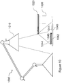
- the figure 1 represents a test and analysis system 10 according to the teaching of the patent US 7,298,885 .
- the system 10 comprises a scanner 12, a screen 14 and a support 16 for receiving a test device 20 and introducing it into the body of the scanner 12.
- the device 20 has a test zone 22 and an identifier 24 which allows identify the device 20 (in particular determine the analysis to be performed).
- the scanner 12 can then identify the type of device 20 by means of the identifier 24 and automatically apply an appropriate analysis.
- the screen 14 makes it possible, for example, to display the test zone 22, the progress of the analysis (the remaining time), the options that can be selected by a user (for example analysis parameters) and / or the results. of the analysis of the device 20.
- the system 10 has disadvantages, particularly in terms of costs, versatility (this system is suitable only for a specific type of device) and implementation (this system is not suitable for use in the field).
- test devices for example biological or chemical test devices, in particular in uncontrolled environments and / or in the absence of qualified personnel.
- the analysis step comprises a step of comparing the at least one determined geometric characteristic with at least one geometric characteristic of a graphical element identified in a portion of an observation surface represented in a another image of the same test device.
- the method further includes a step of projecting at least a portion of the at least a portion of the viewing surface.
- the steps of identifying a test device, identifying a graphic element in the at least a portion of the observation surface and determining at least one geometric feature are repeated for at least a second image of the test device, the step of analyzing comprising a step of comparing at least one geometric characteristic determined from a first image of a test device with at least one geometric characteristic determined from a second image of the same test device.
- the method further comprises a step of determining a marker according to the visual reference, the at least one geometric characteristic being determined according to the determined reference.
- the method further comprises a notification step of obtaining a new image, the notification being notified according to an identification of the test device determined from an image obtained previously.
- the notification step comprises a step of obtaining test information, the test information being obtained according to the identification of the test device determined from the image obtained previously. .
- the method further comprises a step of storing the received image and the identification of the test device determined from the image obtained.
- the at least one geometric feature includes size, shape, and / or coordinates.
- the invention also relates to a computer program comprising instructions adapted to the implementation of each of the steps of the method described above, when said program is executed on a computer.
- the benefits provided by this computer program are similar to those mentioned above.
- the invention also relates to an analysis system of a test device comprising means adapted to the implementation of each of the steps of the method described above.
- the advantages provided by this system are similar to those mentioned in the process.
- the system comprises a device for image capture, image correction and analysis of smartphone-type images.
- the system includes a first image capture device and a second image analysis device, separate from the first device.
- the invention relates to a system and a method for analyzing test devices, in particular biological or chemical tests, allowing, for example, the detection, enumeration and / or classification of colonies of microorganisms, using the same visual reference to identify the device (allowing, preferably, to select a type of analysis to be performed) and to analyze the device by image analysis, without requiring a particular point of view when taking pictures of the device.
- Embodiments of the invention are suitable for observing growth of colonies of microorganisms to analyze their evolution over time.
- an analysis unit such as a smartphone (smartphone) or a tablet equipped with an image sensor, comprising a suitable software application, can be used to capture an image of the device, the captured images that can be processed and analyzed either by the analysis unit itself (if it has the necessary resources) or, for example, by a remote server to which images or parts of images are transferred.
- the analysis unit may consist of a simple digital camera.
- the analysis method is implemented in the analysis unit, using a suitable application, which is used for image capture, normalization of acquired images. and their analysis.
- the user can further be guided in the use of the application, for example to indicate the moments to which images should be taken.
- test device is now described in more detail.
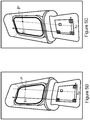
- FIGS. 2A and 2B represent front views of the same test device 100 that can be used by an analysis system, according to embodiments, in two different configurations.
- the embodiments of the invention described below are directed to a device for the biological growth of colonies of microorganisms.
- the invention is not limited to this field.
- the test device 100 may take an open configuration, as shown in FIG. Figure 2A or a closed configuration as shown on the Figure 2B .
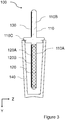
- the figure 3 represents a sectional view, in profile, of the test device 100 illustrated on the Figures 2A and 2B , in the configuration of the Figure 2B .
- the test device 100 comprises a support 110, a test zone 120, a visual reference 130 and a protective envelope 140.
- the visual reference 130 allows an identification of the test device 100 and a normalization of an image representing this device, typically by determining a geometric deformation of a representation of the test area according to a predetermined format of the visual reference.
- the support 110 comprises a first part 110A, called the lower part, and a second part 110B, called the upper part, separated by a closing abutment 110C.
- the lower portion 110A includes the test area 120. It is configured to be insertable into the shroud 140, as shown on the Figures 2B and 3 . It is observed here that the closure stop 110C may be an insert.
- the protective envelope 140 forms, with the support 110, a closed system enclosing and isolating the test zone 120 from the external environment.
- the protective envelope 140 is ideally transparent in order to allow regular image captures during the test, without exposing the test zone 120 to ambient air and, thus, to possible external contamination.
- the upper part 110B can be used for the manipulation of the test device 100 without a user touching the test zone 120 and may contaminate it.
- the visual reference 130 is here arranged on the upper part 110B, ideally above the stop 140 and outside the protective envelope 140 so that its reading is not disturbed.
- the test zone 120 here comprises a development medium 120A, for example a nutrient medium, and an observation surface 120B.
- the development medium 120A makes it possible for example the development of microorganisms and / or chemical and / or biological markers making it possible to reveal the presence of biological activities of the microorganisms and / or making it possible to count and / or classify these microorganisms. organizations.
- test zone 120 and the visual reference 130 are arranged on the same face of the support 110, preferably in the same XY plane (the X axis being oriented along the width of the device 100 and the axis Y being oriented along the length of the device 100) or in parallel planes.
- the viewing surface 120B preferably covers the developing medium 120A which is, for example, planar and square or circular in shape.
- the development medium 120A may comprise a support such as a buffer which may consist of cellulose derivatives for retaining a liquid or a gel allowing the development of microorganisms.
- the protective envelope 140 may serve as a container to receive (preferably temporarily) a sample to be analyzed in which the test area 120 may be dipped.
- test zone 120 After the test zone 120 has been contacted with a test sample and, if appropriate, the excess sample has been removed from the test zone 120, the test device 100 is allowed to incubate for a period of time. For a time, the test zone 120 is protected in the protective envelope 140. As described below, photographs of the device can be taken and analyzed according to the nature of the tests to be performed.
- the visual reference 130 is, for example, a visual identifier of the type QR code (abbreviation of Quick Response code in English terminology), a barcode or other identifier having a predetermined format.
- This format can be defined, for example, by the device manufacturer, the developer of an image processing software according to embodiments of the invention or by an analysis laboratory which receives images of the test device. .
- the visual reference 130 typically allows to determine an analysis to be performed. This reference may be common to several test devices or specific to each test device.
- the identifier provided by the visual reference 130 can be used as a database entry to obtain and / or provide information such as a microphone type. -organism, a manufacturer, a test protocol, a validity date, the name of a user, a date of use, etc.
- This database can be initially completed by the manufacturer of the test device and then enriched when the test device is used.
- Several databases, corresponding to several test devices and / or several types of information, can be used.
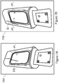
- the Figure 4B illustrates the same test device 100 at a time t 1 , for example 24h after the time t 0 .
- the characteristics of the tasks observed for example its position, size, color and shape, can be recorded.
- the task O 1 has not evolved between the instants t 0 and t 1 (ie the tasks O 1 (t 0 ) and O 1 (t 1 ) are equivalent) and the task O 2 has appeared on the surface of observation 120B.
- the observation surface 120B shows, at an instant t 2 , for example 48h after the instant t 0 , the tasks O 1 and O 2 already observed previously and a new task O 3 .
- the size of the task O 2 has increased here compared to the observation made at time t 1 .
- the characteristics of the tasks observed for example its position, size, color and shape, are recorded here.
- the figure 4D illustrates the same device 100 at a time t 3 , for example 72h after the time t 0 .
- the size of the tasks O 2 and O 3 has increased compared to the observation made at the instant t 2 , the size of the task O 3 having increased more rapidly than the of the task O 2 .
- the characteristics of the tasks observed for example its position, size, color and shape, are preferably recorded.
- the characteristics of the task O 1 have not evolved between the instants t 0 to t 3 . It can thus be concluded that the task O 1 is not representative of a colony of microorganism. It may be, for example, a dust. On the other hand, it can be considered that the O 2 task represents a colony of slow growing microorganisms (under the test conditions) and that the O 3 task represents a colony of fast-growing microorganisms (always under the conditions test).
- colonies of microorganisms appear in "waves" of time if there are subpopulations in the sample analyzed. If image captures are fairly frequent, the detection of such waves may be an indication of the number of subpopulations, being observed that it takes about one million microorganisms for a colony to be observable to the eye. but only a few thousand microorganisms can usually be detected by a x10 magnification (often offered by image sensors on a smartphone or tablet).
- the rate at which the size of a colony grows is an indication of the doubling time (in exponential phase) constituting an indication of the colony-specific strain, being observed that between the initial moment and the exponential phase, the Bacteria generally know a so-called latency phase during which they adapt to their new environment and do not multiply or little.
- Colonies are usually round but may be truncated, overlapping, or have different shapes (irregular, filamentous, rhizoid, etc.) depending on the type of colony.
- the color of a colony is usually white but may be transparent, eggshell-colored, or otherwise.
- nutrient media can generate distinct colony colors or halos around colonies. These aspects are well known in the art. Analysis of an image can then include evaluation of the shape, color, border, etc. Other optical techniques make it possible to observe the relief and the texture of the colonies, for example by analyzing the deformation of a known pattern projected on and reflected by the test zone 120.
- Relief and texture information is complementary to information on size, rate of growth, color, transparency, and the like and increases the ability of the system to properly classify colonies.
- the user is asked to capture the images that are then analyzed. It can thus be alerted at the beginning of the test of the number of images to be taken and the times at which the images must be taken. It can also be notified whenever an image needs to be taken.
- the visual reference 130 allows in particular the execution of a normalization step so that images taken from different points of view can be compared. It is thus possible to normalize the image captures by the knowledge of the format of the visual reference 130.
- FIGS. 5A , 5B and 5C illustrate a first example of normalization based on a predetermined format of a visual reference to allow the comparison of images of a test device obtained from several different points of view.
- the visual reference and the observation surface of the test device are arranged in the same plane.
- the Figure 5A illustrates an example of a visual reference used as a geometric reference.
- the visual reference 130 used here is a QR code having a predetermined size.
- the QR code includes three distinct squares C 1 , C 2 and C 3 , called position squares, arranged in the lower left, lower right and upper left corners, respectively, as illustrated.
- the QR code further comprises a fourth square C 4 , called alignment square (the QR code can include several alignment squares according to the version of the QR code implemented).
- the alignment square or squares enable correction of an image of the code with respect to the size, orientation and angle of image capture.
- the center of the position squares C 1 , C 2 and C 3 is used to form a geometric reference point in which the coordinates of the points of the visual reference and the coordinates of the points of the viewing surface of the test device can be expressed. (the visual reference and the observation surface are here placed in the same plane).
- the center of the position square C 1 forms the origin of the marker
- the center of the position squares C 1 and C 2 forms the abscissa axis as well as the unit vector along this axis
- the center of the position squares C 1 and C 3 forms the y-axis and the unit vector along this axis.
- FIGS. 5B and 5C illustrate two images representing a test device 100 observed from two different points of view.
- FIGS. 6A, 6B and 6C illustrate a second example of normalization based on a predetermined format of a visual reference to allow the comparison of images of a test device obtained from several different points of view.
- FIGS. 6A, 6B and 6C show three images representing the same test device observed according to three different points of view at three different times.
- the origin of the marker is the lower left corner of the images and the unit is the pixel.
- standard image analysis techniques implemented, for example, to identify QR codes, can be used to identify the position and alignment squares C 1 , C 2 , C 3 and C 4 and determining the coordinates of their center, denoted ( x 1 , y 1 ) , ( x 2 , y 2 ) , ( x 3 , y 3 ) and ( x 4 , y 4 ) , respectively, in a frame linked to the image in which are identified these squares.
- the Figure 6A represents a first image 600 of a test device obtained according to a first point of view, in which it is possible to identify the position and alignment squares C 1 1 , C 1 2 , C 1 3 and C 1 4 and determine the coordinates of their center, denoted (x 1 1 , y 1 1 ) , ( x 1 2 , y 1 2 ), ( x 1 3 , y 1 3 ) and ( x 1 4 , y 1 4 ) , respectively , in a frame linked to the image in which these squares are identified.
- the image 600 has for example been obtained at a time t 1 .
- Figure 6B represents a second image 605 of the test device obtained according to a second point of view, in which it is possible to identify the position and alignment squares C 2 1 , C 2 2 , C 2 3 and C 2 4 and determine the coordinates of their center, denoted ( x 2 1 , y 2 1 ) , ( x 2 2 , y 2 2 ) , ( x 2 3 , y 2 3 ) and ( x 2 4 , y 2 4 ) , respectively, in a reference linked to the image in which these squares are identified.
- the image 605 has for example been obtained at a time t 2 .
- the Figure 6C represents a third image 610 of the test device obtained according to a third point of view, in which it is possible to identify the position and alignment squares C 3 1 , C 3 2 , C 3 3 and C 3 4 and determine the coordinates of their center.
- the image 610 has for example been obtained at a time t 3 .
- the coordinates of a task identified in an observation surface represented in a first image can be projected into the corresponding observation surface of a second image, for example the image 605 , to allow a comparison of these coordinates with those of the corresponding task of the viewing surface shown in the second image.
- the coordinates of a task identified in an observation surface represented in a first image can be projected into the corresponding observation surface of a third image, for example the image 610, to allow a comparison of these coordinates with those of the corresponding task of the viewing surface shown in the third image.
- the visual reference is used to define the points to be used to perform the projection, it may be points distinct from the visual reference.
- the visual reference can be used to identify the viewing surface of the test device if the positions of the test device and the visual reference are predetermined.
- FIGS. 7A and 7B illustrate an exemplary image correction according to a particular embodiment, between a first image 700 and a second image 705, respectively.
- Such a correction can be made following the detection of a suspicion of defect in an image or in a sequence of images, for example when an unexpected element is detected (because, for example, of its shape, its color , its size or its evolution over time).
- the Figures 7A and 7B show two images representing the same test device observed according to two different points of view at two moments close to each other.
- the image represented on the Figure 7B has been taken here following the detection of a potential defect on the image represented on the Figure 7A .
- the analysis of the viewing surface of the test device shown in FIG. Figure 7A allows to identify a task P 1 1 and to detect a potential fault DS because, for example, of its shape and its color.
- Another image is obtained from a different point of view, here the image represented on the Figure 7B .
- This image is acquired as soon as possible after obtaining the image on which a potential defect is detected.
- the application may, after the detection of a potential fault, alert the user and suggest the acquisition of a new image to remove doubt.
- the analysis of the observation surface of the test device represented on the Figure 7B identifies the tasks P 2 1 and P 2 2 but does not reveal any potential defects. It can therefore be deduced that the potential fault identified on the observation surface of the test device represented on the Figure 7A is a defect that can be ignored.
- an analysis of the area around the viewing surface of the test device shown in the image used to determine whether it is a defect or not can be performed to identify the defect. previously identified potential.
- the identification of this potential defect on the image of the Figure 7B outside the observation surface, confirms that it is a defect related to the protective envelope 140.
- the defect presented on the figure 7 is a scratch or mark on the outer surface of the shroud 140. It could also be, for example, a droplet of condensation on the inner surface of the shroud 140.
- the change of point of view allows moreover to reveal, on the image of the Figure 7B , the task P 2 2 that was hidden on the image of the Figure 7B .
- the figure 8 represents an example of an analysis unit 800 that can be used by an analysis system according to a particular embodiment.
- the analysis unit 800 for example a smartphone, here comprises an image sensor denoted CAP, a memory denoted MEM, a microprocessor denoted MP and an input / output module denoted I / O. These different elements are here controlled by an application executed on the analysis unit.
- the image sensor CAP is capable of taking images of the test device 100 with at least a portion of the viewing surface 120B and the visual reference 130 with, preferably, a resolution for analyzing the viewing surface depending on the type of test to be performed.
- image capture is performed by a user upon recommendation of the application. A captured image is then transferred to the MP microprocessor for processing.
- the MEM memory can be used to store the application as well as captured images. It can also be used to store, in the application or independently, counting, classification and fault determination rules, incubation rules and results validation rules. Alternatively, these rules can be stored in a remote system.
- the memory MEM may, for example, be updated by the end user, by a laboratory, by the developer of the software or by the manufacturer of the device 100.
- the microprocessor MP receives an image acquired by the image sensor CAP.
- a first test is preferably performed to determine whether the acquired image is exploitable, for example if it is sufficiently clear, if it comprises a representation of the visual reference and at least a portion of the viewing surface.
- the visual reference is then preferably analyzed, for example to access and / or verify characteristics of the test device 100, for example if it is not expired and / or is compatible with the conditions of the test devices. tests envisaged. Characteristics of the analysis unit 700 can then be obtained, for example geolocation data, a time reference (present moment), etc.
- the microprocessor MP proceeds to a step of normalizing an image acquired according to the visual reference.
- a step may notably consist in the definition of a particular reference point in which the coordinates of the points analyzed are expressed or in the projection of the image (or of certain points of the image) according to the visual reference and according to another image.
- the acquired image is then analyzed, according to the determined normalization, in order, for example, to identify tasks and to compare them to tasks identified in a previous step.
- an input / output module I / O allows a user to control the analysis unit, for example to capture images, and to enter information, for example comments.
- This module also makes it possible to send notifications to the user, for example to ask him to carry out actions such as capturing an image, to warn him of future actions, for example to warn him that it will be necessary to capture a new image in a time of n minutes or n hours (n being typically determined by the application according to the nature of the tests to be performed), or give him indications or information, for example indications relating to the test conditions and / or the test device.
- the I / O input / output module can also be used to exchange data with a remote system, for example a server, for example to transmit test results. Such exchanges may be predetermined and / or may be masked vis-à-vis the user.
- one or more elements of the analysis unit are absent or not used, corresponding elements of another unit being used.
- an image processing for example a projection
- the analysis unit can then be used as an image sensor and user interface.
- the application used can provide information to the user and guide him in the tests to be performed, for example to indicate to him how to obtain a sample and put it in contact with the test area of the test device, which are the test conditions, for example time and temperature of incubation, assisting in the taking of images, for example by means of alignment or lighting indications. Sample images can also be shown to help him.
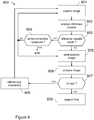
- the figure 9 illustrates steps of an example of an analysis method according to an embodiment.
- the analysis method 900 here comprises the steps 901 to 909. It can be implemented, for example, using the system 800 illustrated on the figure 8 for example in the form of an application.
- step 901 The purpose of step 901 is to capture an image of the test device 100.
- a notification may be sent to a user after the user has launched the application or has launched a new test. , so that it captures an image of the test device.
- the first captured image can be obtained before a sample is presented to the test area of the test device, for example to obtain a reference image of the test device, just after a sample is presented to the test area. testing the test device to have a first test start image or after a certain incubation time.
- the user can take other images, for example representative images of the test environment or the source of the sample.
- a quality test is advantageously carried out to check the quality of the image acquired, for example its sharpness and / or the presence of a representation of at least a portion of the viewing surface. If the quality is not sufficient, for example with regard to a predetermined criterion, the user may be asked to capture another image.
- the acquired image is stored with additional information (metadata), such as an identifier of the image, an identifier of the analysis unit used to capture the image, an identifier of the image.
- metadata such as an identifier of the image, an identifier of the analysis unit used to capture the image, an identifier of the image.
- user who has captured the image an indication of the source of the sample, an indication of the temperature of the environment in which the test is taking place, geolocation information such as GPS data (acronym for global positioning system in terminology Anglo-Saxon) and / or an indication of the date and time of capture of the image.
- a first analysis of the acquired image is performed to identify a visual reference having a predetermined format (for example a QR code or a bar code), using a standard algorithm .
- the identifier corresponding to the visual reference can be used to obtain data associated with this identifier in one or more databases.
- data are, for example, a manufacturer, a test protocol and / or a validity date.
- a link is also established between this identifier, the acquired image and, preferably, at least some of the additional information or metadata referred to above.
- the image and this additional information may in particular be stored in the database or databases described above in connection with the identifier.
- a test is then carried out to determine whether the visual reference is valid, for example if its format conforms to the expected format and / or if it defines an expected identifier (step 903).
- the identifier corresponding to the visual reference is valid, that is to say, for example, if it corresponds to a non-expired test device and corresponding to the tests to be performed. It can also be verified that the test area is well represented in the image or that there is, a priori, no artifact.
- a help message is sent to the user to indicate the nature of the the anomaly (eg " device expired, continue? ”) and / or to indicate the reason for the failure and help it overcome it (eg " proportion of insufficient test area: take a new, better framed image " or " Potential artifact: take a new image from a different angle ”) .
- the acquired image can be analyzed.
- the visual reference is analyzed to determine normalization of the acquired image (step 905).
- normalization may consist in particular in determining a "normalized" reference point in which the coordinates of the points studied are expressed or in projecting the image being analyzed or part of this image according to the visual reference of this image and the visual reference of a previously acquired image (of the same test device).
- step 906 the image is analyzed (step 906).
- This analysis can be conducted in an analysis unit, for example a smartphone or a tablet, or in a system, for example a remote server.
- the analysis includes the identification and characterization of elements on an observation surface, typically the identification and characterization of tasks by their color, shape and size.
- the analysis also preferably includes, for the second acquired image and the following ones, the comparison of the characteristics of the elements identified with those of the elements identified on observation surfaces of previous images.
- this analysis step includes the comparison of characteristics expressed from a common (or "normalized") coordinate system or the comparison of characteristics related to a first image with characteristics of a one-second projection. image (or part of the second image). For these purposes, one or more prior images (or characteristics obtained by analysis of these images) are obtained, depending on the identifier of the test device. This analysis makes it possible, for example, to identify colonies of bacteria, to count them and to compare them between successive images.
- a test is performed to determine whether the tests are completed or not, that is, whether or not other images are to be acquired and analyzed.
- the end of the test can be predetermined, for example according to a time scale, or linked to an observation, for example a number of detected colonies.
- step 907 the previous steps (steps 901 to 907) are repeated to process a new image. These steps are repeated after a predetermined time (step 908), for example an incubation time.
- test report is preferably established (step 909).
- it contains statistics on the identified elements, their characteristics and their evolution.
- the analysis of an observation surface represented in an image can begin after the capture of the latter, without waiting for the identification of the test device.
- image analysis may be performed after a large number of images, or all images have been acquired. It is also possible to analyze an image while capturing another image.
- the figure 10 represents an example of an analysis system 1000 according to a particular embodiment.
- the system 1000 is particularly suitable for implementation in varied environments.
- the system 1000 comprises an artificial light source 1010 (natural light is just as good or better than artificial light, but is not always available in sufficient quantity for a good shot) for example a desk lamp, an analysis unit 1020, for example a smartphone, a support 1030 for the analysis unit, for example a drink can, and a test device 1040.
- an artificial light source 1010 natural light is just as good or better than artificial light, but is not always available in sufficient quantity for a good shot
- an analysis unit 1020 for example a smartphone
- a support 1030 for the analysis unit for example a drink can
- a test device 1040 for example a test device 1040.
- the device 1040 comprises a visual reference 1041, a test area 1042 and an observation surface 1043 protected by a protective envelope 1044.
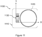
- the figure 11 represents a front view of a test device 1100 according to another embodiment.
- the test device 1100 here comprises a support 1110, a test zone 1120 and a visual reference 1130.
- the visual reference 1130 is a barcode whose format can be used to define a reference mark in which can be expressed the coordinates of elements detected on the observation surface of the test zone 1120.
- the abscissa axis is defined as the lower edge of the barcode and the ordinate axis as the left edge. barcode, the origin of the marker being the lower left corner of the barcode (when the device is seen from the front, the test area being placed on the right).
- test device 1100 can be used in the context of the analysis systems and analysis methods described above.
Landscapes
- Engineering & Computer Science (AREA)
- Theoretical Computer Science (AREA)
- Physics & Mathematics (AREA)
- General Physics & Mathematics (AREA)
- Computer Vision & Pattern Recognition (AREA)
- Chemical & Material Sciences (AREA)
- Software Systems (AREA)
- General Engineering & Computer Science (AREA)
- Bioinformatics & Cheminformatics (AREA)
- Organic Chemistry (AREA)
- Zoology (AREA)
- Wood Science & Technology (AREA)
- Health & Medical Sciences (AREA)
- Life Sciences & Earth Sciences (AREA)
- Geometry (AREA)
- Quality & Reliability (AREA)
- Multimedia (AREA)
- Sustainable Development (AREA)
- Biomedical Technology (AREA)
- Analytical Chemistry (AREA)
- Microbiology (AREA)
- Biochemistry (AREA)
- General Health & Medical Sciences (AREA)
- Genetics & Genomics (AREA)
- Biotechnology (AREA)
- Apparatus Associated With Microorganisms And Enzymes (AREA)
- Image Processing (AREA)
- Analysing Materials By The Use Of Radiation (AREA)
Applications Claiming Priority (1)
| Application Number | Priority Date | Filing Date | Title |
|---|---|---|---|
| FR1853321A FR3080211B1 (fr) | 2018-04-16 | 2018-04-16 | Systeme et procede d'analyse de dispositifs de test |
Publications (2)
| Publication Number | Publication Date |
|---|---|
| EP3557528A1 true EP3557528A1 (de) | 2019-10-23 |
| EP3557528B1 EP3557528B1 (de) | 2022-07-13 |
Family
ID=63143231
Family Applications (1)
| Application Number | Title | Priority Date | Filing Date |
|---|---|---|---|
| EP19169463.7A Active EP3557528B1 (de) | 2018-04-16 | 2019-04-16 | System und verfahren zur analyse von testvorrichtungen |
Country Status (3)
| Country | Link |
|---|---|
| US (1) | US11145044B2 (de) |
| EP (1) | EP3557528B1 (de) |
| FR (1) | FR3080211B1 (de) |
Citations (10)
| Publication number | Priority date | Publication date | Assignee | Title |
|---|---|---|---|---|
| WO1998014777A1 (en) * | 1996-09-30 | 1998-04-09 | California South Pacific Investors | Detection of contaminants in food |
| US7298885B2 (en) | 2002-11-27 | 2007-11-20 | 3M Innovative Properties Company | Biological growth plate scanner with automated image processing profile selection |
| EP2453242A1 (de) * | 2010-11-12 | 2012-05-16 | Alere San Diego, Inc. | Verfahren und System mit Lateralfluss-Immunoassay-Testvorrichtung mit integrierter Qualitätssicherungsetikette |
| WO2013116831A1 (en) * | 2012-02-03 | 2013-08-08 | University Of Cincinnati | Method and system for analyzing a colorimetric assay |
| WO2014025415A2 (en) * | 2012-08-08 | 2014-02-13 | Scanadu Incorporated | Method and apparatus for performing and quantifying color changes induced by specific concentrations of biological analytes in an automatically calibrated environment |
| WO2014080212A2 (en) * | 2012-11-22 | 2014-05-30 | Microlab Devices Limited | Test strip and methods and apparatus for reading the same |
| WO2014099643A1 (en) * | 2012-12-20 | 2014-06-26 | 3M Innovative Properties Company | Method of differentiating microbial colonies in an image |
| US20150241358A1 (en) * | 2012-08-08 | 2015-08-27 | Scanadu Incorporated | Method and apparatus for determining analyte concentration by quantifying and interpreting color information captured in a continuous or periodic manner |
| US20160048739A1 (en) * | 2014-08-15 | 2016-02-18 | Scanadu Incorporated | Precision luxmeter methods for digital cameras to quantify colors in uncontrolled lighting environments |
| WO2016172527A2 (en) * | 2015-04-23 | 2016-10-27 | Bd Kiestra B.V. | Colony contrast gathering |
Family Cites Families (10)
| Publication number | Priority date | Publication date | Assignee | Title |
|---|---|---|---|---|
| US5492835A (en) * | 1994-07-13 | 1996-02-20 | Gerald J. Churchill | Swab identification testing device and method |
| US6230548B1 (en) * | 1998-07-14 | 2001-05-15 | Chi-Neng Arthur Han | System for testing properties of materials |
| US7899681B2 (en) * | 2002-03-29 | 2011-03-01 | 3M Innovative Properties Company | Electronic management of sterilization process information |
| EP2416702A2 (de) * | 2009-04-07 | 2012-02-15 | Reveal Sciences, Llc | Vorrichtung, verfahren und gerät für bologisches testen mit einer mobilen vorrichtung |
| JP5575534B2 (ja) * | 2010-04-30 | 2014-08-20 | 株式会社東芝 | 超音波診断装置 |
| US8506901B2 (en) * | 2010-11-03 | 2013-08-13 | Teco Diagnostics | All-in-one specimen cup with optically readable results |
| WO2013096801A1 (en) * | 2011-12-23 | 2013-06-27 | Abbott Point Of Care Inc | Reader devices for optical and electrochemical test devices |
| US11293873B2 (en) * | 2015-09-08 | 2022-04-05 | Xerox Corporation | Methods and devices for improved accuracy of test results |
| EP3380825B1 (de) * | 2015-11-23 | 2020-09-23 | CellTool GmbH | Vorrichtung und verfahren zum analysieren biologischer objekte mit raman spektroskopie |
| US11915810B2 (en) * | 2016-12-14 | 2024-02-27 | Reliant Immune Diagnostics, Inc. | System and method for transmitting prescription to pharmacy using self-diagnostic test and telemedicine |
-
2018
- 2018-04-16 FR FR1853321A patent/FR3080211B1/fr active Active
-
2019
- 2019-04-15 US US16/384,439 patent/US11145044B2/en active Active
- 2019-04-16 EP EP19169463.7A patent/EP3557528B1/de active Active
Patent Citations (10)
| Publication number | Priority date | Publication date | Assignee | Title |
|---|---|---|---|---|
| WO1998014777A1 (en) * | 1996-09-30 | 1998-04-09 | California South Pacific Investors | Detection of contaminants in food |
| US7298885B2 (en) | 2002-11-27 | 2007-11-20 | 3M Innovative Properties Company | Biological growth plate scanner with automated image processing profile selection |
| EP2453242A1 (de) * | 2010-11-12 | 2012-05-16 | Alere San Diego, Inc. | Verfahren und System mit Lateralfluss-Immunoassay-Testvorrichtung mit integrierter Qualitätssicherungsetikette |
| WO2013116831A1 (en) * | 2012-02-03 | 2013-08-08 | University Of Cincinnati | Method and system for analyzing a colorimetric assay |
| WO2014025415A2 (en) * | 2012-08-08 | 2014-02-13 | Scanadu Incorporated | Method and apparatus for performing and quantifying color changes induced by specific concentrations of biological analytes in an automatically calibrated environment |
| US20150241358A1 (en) * | 2012-08-08 | 2015-08-27 | Scanadu Incorporated | Method and apparatus for determining analyte concentration by quantifying and interpreting color information captured in a continuous or periodic manner |
| WO2014080212A2 (en) * | 2012-11-22 | 2014-05-30 | Microlab Devices Limited | Test strip and methods and apparatus for reading the same |
| WO2014099643A1 (en) * | 2012-12-20 | 2014-06-26 | 3M Innovative Properties Company | Method of differentiating microbial colonies in an image |
| US20160048739A1 (en) * | 2014-08-15 | 2016-02-18 | Scanadu Incorporated | Precision luxmeter methods for digital cameras to quantify colors in uncontrolled lighting environments |
| WO2016172527A2 (en) * | 2015-04-23 | 2016-10-27 | Bd Kiestra B.V. | Colony contrast gathering |
Non-Patent Citations (1)
| Title |
|---|
| L. JAGANNATHAN; C. V. JAWAHAR: "Perspective Correction Methods for Camera-Based Document Analysis", PROCEEDINGS OF FIRST INTERNATIONAL WORKSHOP ON CAMERA BASED DOCUMENT ANALYSIS AND RÉCOGNITION, August 2005 (2005-08-01), pages 148 - 154 |
Also Published As
| Publication number | Publication date |
|---|---|
| FR3080211B1 (fr) | 2020-05-08 |
| US20190318468A1 (en) | 2019-10-17 |
| FR3080211A1 (fr) | 2019-10-18 |
| US11145044B2 (en) | 2021-10-12 |
| EP3557528B1 (de) | 2022-07-13 |
Similar Documents
| Publication | Publication Date | Title |
|---|---|---|
| EP2661213B1 (de) | System und verfahren zur erkennung der empfindlichkeit einer person gegenüber einer oder mehreren potenziell allergenen substanzen | |
| RU2582268C2 (ru) | Тестовое устройство | |
| CN113361487B (zh) | 异物检测方法、装置、设备及计算机可读存储介质 | |
| FR3081248A1 (fr) | Systeme et procede de determination d’un emplacement pour le placement d'un paquet | |
| EP3224372A1 (de) | Verfahren, system und computerprogrammprodukt zur bestimmung des wachstums von mikroorganismen | |
| EP4232946B1 (de) | Verfahren zur klassifizierung einer sequenz von eingabebildern, die ein teilchen in einer probe im laufe der zeit darstellen | |
| EP4232948B1 (de) | Verfahren zur klassifizierung eines eingabebildes zur darstellung eines partikels in einer probe | |
| EP3608836A1 (de) | Verfahren zum erfassen eines fingerabdruck-bilds | |
| EP3557528B1 (de) | System und verfahren zur analyse von testvorrichtungen | |
| FR3024791A1 (fr) | Procede de determination, dans une image, d’au moins une zone succeptible de representer au moins un doigt d’un individu | |
| FR2852422A1 (fr) | Procede d'identification automatique d'entites dans une image numerique | |
| WO2024194408A1 (fr) | Procédé et dispositif d'anatomopathologie avec identification et suivi d'objets | |
| FR2942319A1 (fr) | Procede de preparation d'une plaque d'analyse virtuelle traitee | |
| WO2015162364A1 (fr) | Procédé, système et produit-programme d'ordinateur pour afficher une image d'un objet | |
| FR3034103A1 (fr) | Procede de mesure de la concentration de microorganismes dans un liquide | |
| Esfandi et al. | Determining the efficacy of visual inspections at detecting non-biosecurity–compliant goods | |
| WO2018220198A1 (fr) | Dispositif et procede de detection et d'imagerie d'elements biocontaminants | |
| Szczepanski | Online stereo camera calibration on embedded systems | |
| FR3054708B1 (fr) | Procede de comparaison d'objets et dispositif associe | |
| WO2016083703A1 (fr) | Procédé et dispositif de détection d'ensemencement et installation automatisée d'ensemencement équipée d'un tel dispositif de détection | |
| WO2021219699A1 (en) | Methods and apparatus for stain assessment | |
| CN112911280B (zh) | 镜头状态的检测方法及装置、电子设备、存储介质 | |
| FR3007612A1 (fr) | Dispositif de prise de vue pour l'elaboration securisee de preparations medicamenteuses, support de positionnement d'objets associe, et systeme incluant un tel dispositif et un tel support | |
| FR3050046B1 (fr) | Procede et dispositif electronique d'aide a la determination, dans une image d'un echantillon, d'au moins un element d'interet parmi des elements biologiques, programme d'ordinateur associe | |
| Chowdhury | Detection of contamination in pharmaceutical tanks: Implementing a camera-based method and Convolutional Neural Network for image recognition to automate visual inspection of pharmaceutical stainless steel tanks |
Legal Events
| Date | Code | Title | Description |
|---|---|---|---|
| PUAI | Public reference made under article 153(3) epc to a published international application that has entered the european phase |
Free format text: ORIGINAL CODE: 0009012 |
|
| STAA | Information on the status of an ep patent application or granted ep patent |
Free format text: STATUS: THE APPLICATION HAS BEEN PUBLISHED |
|
| AK | Designated contracting states |
Kind code of ref document: A1 Designated state(s): AL AT BE BG CH CY CZ DE DK EE ES FI FR GB GR HR HU IE IS IT LI LT LU LV MC MK MT NL NO PL PT RO RS SE SI SK SM TR |
|
| AX | Request for extension of the european patent |
Extension state: BA ME |
|
| STAA | Information on the status of an ep patent application or granted ep patent |
Free format text: STATUS: REQUEST FOR EXAMINATION WAS MADE |
|
| 17P | Request for examination filed |
Effective date: 20200311 |
|
| RBV | Designated contracting states (corrected) |
Designated state(s): AL AT BE BG CH CY CZ DE DK EE ES FI FR GB GR HR HU IE IS IT LI LT LU LV MC MK MT NL NO PL PT RO RS SE SI SK SM TR |
|
| STAA | Information on the status of an ep patent application or granted ep patent |
Free format text: STATUS: EXAMINATION IS IN PROGRESS |
|
| 17Q | First examination report despatched |
Effective date: 20200603 |
|
| RIC1 | Information provided on ipc code assigned before grant |
Ipc: G01N 21/78 20060101ALI20211119BHEP Ipc: C12M 1/34 20060101ALI20211119BHEP Ipc: G06T 5/00 20060101ALI20211119BHEP Ipc: G06T 7/33 20170101AFI20211119BHEP |
|
| GRAP | Despatch of communication of intention to grant a patent |
Free format text: ORIGINAL CODE: EPIDOSNIGR1 |
|
| STAA | Information on the status of an ep patent application or granted ep patent |
Free format text: STATUS: GRANT OF PATENT IS INTENDED |
|
| INTG | Intention to grant announced |
Effective date: 20220211 |
|
| GRAS | Grant fee paid |
Free format text: ORIGINAL CODE: EPIDOSNIGR3 |
|
| GRAA | (expected) grant |
Free format text: ORIGINAL CODE: 0009210 |
|
| STAA | Information on the status of an ep patent application or granted ep patent |
Free format text: STATUS: THE PATENT HAS BEEN GRANTED |
|
| AK | Designated contracting states |
Kind code of ref document: B1 Designated state(s): AL AT BE BG CH CY CZ DE DK EE ES FI FR GB GR HR HU IE IS IT LI LT LU LV MC MK MT NL NO PL PT RO RS SE SI SK SM TR |
|
| REG | Reference to a national code |
Ref country code: CH Ref legal event code: EP |
|
| REG | Reference to a national code |
Ref country code: DE Ref legal event code: R096 Ref document number: 602019016883 Country of ref document: DE |
|
| REG | Reference to a national code |
Ref country code: AT Ref legal event code: REF Ref document number: 1504659 Country of ref document: AT Kind code of ref document: T Effective date: 20220815 |
|
| REG | Reference to a national code |
Ref country code: IE Ref legal event code: FG4D Free format text: LANGUAGE OF EP DOCUMENT: FRENCH |
|
| RAP2 | Party data changed (patent owner data changed or rights of a patent transferred) |
Owner name: BIOMIRE |
|
| REG | Reference to a national code |
Ref country code: LT Ref legal event code: MG9D |
|
| REG | Reference to a national code |
Ref country code: NL Ref legal event code: MP Effective date: 20220713 |
|
| PG25 | Lapsed in a contracting state [announced via postgrant information from national office to epo] |
Ref country code: SE Free format text: LAPSE BECAUSE OF FAILURE TO SUBMIT A TRANSLATION OF THE DESCRIPTION OR TO PAY THE FEE WITHIN THE PRESCRIBED TIME-LIMIT Effective date: 20220713 Ref country code: RS Free format text: LAPSE BECAUSE OF FAILURE TO SUBMIT A TRANSLATION OF THE DESCRIPTION OR TO PAY THE FEE WITHIN THE PRESCRIBED TIME-LIMIT Effective date: 20220713 Ref country code: PT Free format text: LAPSE BECAUSE OF FAILURE TO SUBMIT A TRANSLATION OF THE DESCRIPTION OR TO PAY THE FEE WITHIN THE PRESCRIBED TIME-LIMIT Effective date: 20221114 Ref country code: NO Free format text: LAPSE BECAUSE OF FAILURE TO SUBMIT A TRANSLATION OF THE DESCRIPTION OR TO PAY THE FEE WITHIN THE PRESCRIBED TIME-LIMIT Effective date: 20221013 Ref country code: NL Free format text: LAPSE BECAUSE OF FAILURE TO SUBMIT A TRANSLATION OF THE DESCRIPTION OR TO PAY THE FEE WITHIN THE PRESCRIBED TIME-LIMIT Effective date: 20220713 Ref country code: LV Free format text: LAPSE BECAUSE OF FAILURE TO SUBMIT A TRANSLATION OF THE DESCRIPTION OR TO PAY THE FEE WITHIN THE PRESCRIBED TIME-LIMIT Effective date: 20220713 Ref country code: LT Free format text: LAPSE BECAUSE OF FAILURE TO SUBMIT A TRANSLATION OF THE DESCRIPTION OR TO PAY THE FEE WITHIN THE PRESCRIBED TIME-LIMIT Effective date: 20220713 Ref country code: FI Free format text: LAPSE BECAUSE OF FAILURE TO SUBMIT A TRANSLATION OF THE DESCRIPTION OR TO PAY THE FEE WITHIN THE PRESCRIBED TIME-LIMIT Effective date: 20220713 Ref country code: ES Free format text: LAPSE BECAUSE OF FAILURE TO SUBMIT A TRANSLATION OF THE DESCRIPTION OR TO PAY THE FEE WITHIN THE PRESCRIBED TIME-LIMIT Effective date: 20220713 |
|
| REG | Reference to a national code |
Ref country code: AT Ref legal event code: MK05 Ref document number: 1504659 Country of ref document: AT Kind code of ref document: T Effective date: 20220713 |
|
| PG25 | Lapsed in a contracting state [announced via postgrant information from national office to epo] |
Ref country code: PL Free format text: LAPSE BECAUSE OF FAILURE TO SUBMIT A TRANSLATION OF THE DESCRIPTION OR TO PAY THE FEE WITHIN THE PRESCRIBED TIME-LIMIT Effective date: 20220713 Ref country code: IS Free format text: LAPSE BECAUSE OF FAILURE TO SUBMIT A TRANSLATION OF THE DESCRIPTION OR TO PAY THE FEE WITHIN THE PRESCRIBED TIME-LIMIT Effective date: 20221113 Ref country code: HR Free format text: LAPSE BECAUSE OF FAILURE TO SUBMIT A TRANSLATION OF THE DESCRIPTION OR TO PAY THE FEE WITHIN THE PRESCRIBED TIME-LIMIT Effective date: 20220713 Ref country code: GR Free format text: LAPSE BECAUSE OF FAILURE TO SUBMIT A TRANSLATION OF THE DESCRIPTION OR TO PAY THE FEE WITHIN THE PRESCRIBED TIME-LIMIT Effective date: 20221014 |
|
| REG | Reference to a national code |
Ref country code: DE Ref legal event code: R097 Ref document number: 602019016883 Country of ref document: DE |
|
| PG25 | Lapsed in a contracting state [announced via postgrant information from national office to epo] |
Ref country code: SM Free format text: LAPSE BECAUSE OF FAILURE TO SUBMIT A TRANSLATION OF THE DESCRIPTION OR TO PAY THE FEE WITHIN THE PRESCRIBED TIME-LIMIT Effective date: 20220713 Ref country code: RO Free format text: LAPSE BECAUSE OF FAILURE TO SUBMIT A TRANSLATION OF THE DESCRIPTION OR TO PAY THE FEE WITHIN THE PRESCRIBED TIME-LIMIT Effective date: 20220713 Ref country code: DK Free format text: LAPSE BECAUSE OF FAILURE TO SUBMIT A TRANSLATION OF THE DESCRIPTION OR TO PAY THE FEE WITHIN THE PRESCRIBED TIME-LIMIT Effective date: 20220713 Ref country code: CZ Free format text: LAPSE BECAUSE OF FAILURE TO SUBMIT A TRANSLATION OF THE DESCRIPTION OR TO PAY THE FEE WITHIN THE PRESCRIBED TIME-LIMIT Effective date: 20220713 Ref country code: AT Free format text: LAPSE BECAUSE OF FAILURE TO SUBMIT A TRANSLATION OF THE DESCRIPTION OR TO PAY THE FEE WITHIN THE PRESCRIBED TIME-LIMIT Effective date: 20220713 |
|
| PLBE | No opposition filed within time limit |
Free format text: ORIGINAL CODE: 0009261 |
|
| STAA | Information on the status of an ep patent application or granted ep patent |
Free format text: STATUS: NO OPPOSITION FILED WITHIN TIME LIMIT |
|
| PG25 | Lapsed in a contracting state [announced via postgrant information from national office to epo] |
Ref country code: SK Free format text: LAPSE BECAUSE OF FAILURE TO SUBMIT A TRANSLATION OF THE DESCRIPTION OR TO PAY THE FEE WITHIN THE PRESCRIBED TIME-LIMIT Effective date: 20220713 Ref country code: EE Free format text: LAPSE BECAUSE OF FAILURE TO SUBMIT A TRANSLATION OF THE DESCRIPTION OR TO PAY THE FEE WITHIN THE PRESCRIBED TIME-LIMIT Effective date: 20220713 |
|
| 26N | No opposition filed |
Effective date: 20230414 |
|
| PG25 | Lapsed in a contracting state [announced via postgrant information from national office to epo] |
Ref country code: AL Free format text: LAPSE BECAUSE OF FAILURE TO SUBMIT A TRANSLATION OF THE DESCRIPTION OR TO PAY THE FEE WITHIN THE PRESCRIBED TIME-LIMIT Effective date: 20220713 |
|
| PG25 | Lapsed in a contracting state [announced via postgrant information from national office to epo] |
Ref country code: SI Free format text: LAPSE BECAUSE OF FAILURE TO SUBMIT A TRANSLATION OF THE DESCRIPTION OR TO PAY THE FEE WITHIN THE PRESCRIBED TIME-LIMIT Effective date: 20220713 |
|
| REG | Reference to a national code |
Ref country code: CH Ref legal event code: PL |
|
| PG25 | Lapsed in a contracting state [announced via postgrant information from national office to epo] |
Ref country code: LU Free format text: LAPSE BECAUSE OF NON-PAYMENT OF DUE FEES Effective date: 20230416 |
|
| REG | Reference to a national code |
Ref country code: BE Ref legal event code: MM Effective date: 20230430 |
|
| REG | Reference to a national code |
Ref country code: DE Ref legal event code: R081 Ref document number: 602019016883 Country of ref document: DE Owner name: BIOMIRE, FR Free format text: FORMER OWNER: PINQKERTON, SCHILTIGHEIM, FR |
|
| PG25 | Lapsed in a contracting state [announced via postgrant information from national office to epo] |
Ref country code: MC Free format text: LAPSE BECAUSE OF FAILURE TO SUBMIT A TRANSLATION OF THE DESCRIPTION OR TO PAY THE FEE WITHIN THE PRESCRIBED TIME-LIMIT Effective date: 20220713 |
|
| PG25 | Lapsed in a contracting state [announced via postgrant information from national office to epo] |
Ref country code: MC Free format text: LAPSE BECAUSE OF FAILURE TO SUBMIT A TRANSLATION OF THE DESCRIPTION OR TO PAY THE FEE WITHIN THE PRESCRIBED TIME-LIMIT Effective date: 20220713 Ref country code: LI Free format text: LAPSE BECAUSE OF NON-PAYMENT OF DUE FEES Effective date: 20230430 Ref country code: IT Free format text: LAPSE BECAUSE OF FAILURE TO SUBMIT A TRANSLATION OF THE DESCRIPTION OR TO PAY THE FEE WITHIN THE PRESCRIBED TIME-LIMIT Effective date: 20220713 Ref country code: CH Free format text: LAPSE BECAUSE OF NON-PAYMENT OF DUE FEES Effective date: 20230430 |
|
| REG | Reference to a national code |
Ref country code: IE Ref legal event code: MM4A |
|
| PG25 | Lapsed in a contracting state [announced via postgrant information from national office to epo] |
Ref country code: BE Free format text: LAPSE BECAUSE OF NON-PAYMENT OF DUE FEES Effective date: 20230430 |
|
| REG | Reference to a national code |
Ref country code: GB Ref legal event code: 732E Free format text: REGISTERED BETWEEN 20240229 AND 20240306 |
|
| PG25 | Lapsed in a contracting state [announced via postgrant information from national office to epo] |
Ref country code: IE Free format text: LAPSE BECAUSE OF NON-PAYMENT OF DUE FEES Effective date: 20230416 |
|
| PG25 | Lapsed in a contracting state [announced via postgrant information from national office to epo] |
Ref country code: IE Free format text: LAPSE BECAUSE OF NON-PAYMENT OF DUE FEES Effective date: 20230416 |
|
| PG25 | Lapsed in a contracting state [announced via postgrant information from national office to epo] |
Ref country code: BG Free format text: LAPSE BECAUSE OF FAILURE TO SUBMIT A TRANSLATION OF THE DESCRIPTION OR TO PAY THE FEE WITHIN THE PRESCRIBED TIME-LIMIT Effective date: 20220713 |
|
| PG25 | Lapsed in a contracting state [announced via postgrant information from national office to epo] |
Ref country code: BG Free format text: LAPSE BECAUSE OF FAILURE TO SUBMIT A TRANSLATION OF THE DESCRIPTION OR TO PAY THE FEE WITHIN THE PRESCRIBED TIME-LIMIT Effective date: 20220713 |
|
| PGFP | Annual fee paid to national office [announced via postgrant information from national office to epo] |
Ref country code: DE Payment date: 20250429 Year of fee payment: 7 |
|
| PGFP | Annual fee paid to national office [announced via postgrant information from national office to epo] |
Ref country code: FR Payment date: 20250416 Year of fee payment: 7 |
|
| PG25 | Lapsed in a contracting state [announced via postgrant information from national office to epo] |
Ref country code: CY Free format text: LAPSE BECAUSE OF FAILURE TO SUBMIT A TRANSLATION OF THE DESCRIPTION OR TO PAY THE FEE WITHIN THE PRESCRIBED TIME-LIMIT; INVALID AB INITIO Effective date: 20190416 |
|
| PG25 | Lapsed in a contracting state [announced via postgrant information from national office to epo] |
Ref country code: HU Free format text: LAPSE BECAUSE OF FAILURE TO SUBMIT A TRANSLATION OF THE DESCRIPTION OR TO PAY THE FEE WITHIN THE PRESCRIBED TIME-LIMIT; INVALID AB INITIO Effective date: 20190416 |
|
| PG25 | Lapsed in a contracting state [announced via postgrant information from national office to epo] |
Ref country code: TR Free format text: LAPSE BECAUSE OF FAILURE TO SUBMIT A TRANSLATION OF THE DESCRIPTION OR TO PAY THE FEE WITHIN THE PRESCRIBED TIME-LIMIT Effective date: 20220713 |
|
| PGFP | Annual fee paid to national office [announced via postgrant information from national office to epo] |
Ref country code: GB Payment date: 20260327 Year of fee payment: 8 |