EP3557522A1 - Verfahren und vorrichtung zur fusion von panoramavideobildern - Google Patents
Verfahren und vorrichtung zur fusion von panoramavideobildern Download PDFInfo
- Publication number
- EP3557522A1 EP3557522A1 EP17880174.2A EP17880174A EP3557522A1 EP 3557522 A1 EP3557522 A1 EP 3557522A1 EP 17880174 A EP17880174 A EP 17880174A EP 3557522 A1 EP3557522 A1 EP 3557522A1
- Authority
- EP
- European Patent Office
- Prior art keywords
- image
- panoramic video
- moving target
- cuboid
- video image
- Prior art date
- Legal status (The legal status is an assumption and is not a legal conclusion. Google has not performed a legal analysis and makes no representation as to the accuracy of the status listed.)
- Ceased
Links
Images

Classifications
-
- G—PHYSICS
- G06—COMPUTING OR CALCULATING; COUNTING
- G06T—IMAGE DATA PROCESSING OR GENERATION, IN GENERAL
- G06T3/00—Geometric image transformations in the plane of the image
- G06T3/04—Context-preserving transformations, e.g. by using an importance map
-
- G—PHYSICS
- G06—COMPUTING OR CALCULATING; COUNTING
- G06T—IMAGE DATA PROCESSING OR GENERATION, IN GENERAL
- G06T3/00—Geometric image transformations in the plane of the image
- G06T3/40—Scaling of whole images or parts thereof, e.g. expanding or contracting
- G06T3/4038—Image mosaicing, e.g. composing plane images from plane sub-images
-
- G—PHYSICS
- G06—COMPUTING OR CALCULATING; COUNTING
- G06T—IMAGE DATA PROCESSING OR GENERATION, IN GENERAL
- G06T11/00—Two-dimensional [2D] image generation
-
- G—PHYSICS
- G06—COMPUTING OR CALCULATING; COUNTING
- G06T—IMAGE DATA PROCESSING OR GENERATION, IN GENERAL
- G06T3/00—Geometric image transformations in the plane of the image
-
- G—PHYSICS
- G06—COMPUTING OR CALCULATING; COUNTING
- G06T—IMAGE DATA PROCESSING OR GENERATION, IN GENERAL
- G06T3/00—Geometric image transformations in the plane of the image
- G06T3/14—Transformations for image registration, e.g. adjusting or mapping for alignment of images
-
- G—PHYSICS
- G06—COMPUTING OR CALCULATING; COUNTING
- G06T—IMAGE DATA PROCESSING OR GENERATION, IN GENERAL
- G06T3/00—Geometric image transformations in the plane of the image
- G06T3/40—Scaling of whole images or parts thereof, e.g. expanding or contracting
-
- G—PHYSICS
- G06—COMPUTING OR CALCULATING; COUNTING
- G06T—IMAGE DATA PROCESSING OR GENERATION, IN GENERAL
- G06T5/00—Image enhancement or restoration
- G06T5/50—Image enhancement or restoration using two or more images, e.g. averaging or subtraction
-
- G—PHYSICS
- G06—COMPUTING OR CALCULATING; COUNTING
- G06T—IMAGE DATA PROCESSING OR GENERATION, IN GENERAL
- G06T7/00—Image analysis
- G06T7/10—Segmentation; Edge detection
- G06T7/194—Segmentation; Edge detection involving foreground-background segmentation
-
- G—PHYSICS
- G06—COMPUTING OR CALCULATING; COUNTING
- G06T—IMAGE DATA PROCESSING OR GENERATION, IN GENERAL
- G06T7/00—Image analysis
- G06T7/20—Analysis of motion
- G06T7/215—Motion-based segmentation
-
- G—PHYSICS
- G06—COMPUTING OR CALCULATING; COUNTING
- G06T—IMAGE DATA PROCESSING OR GENERATION, IN GENERAL
- G06T2207/00—Indexing scheme for image analysis or image enhancement
- G06T2207/20—Special algorithmic details
- G06T2207/20212—Image combination
- G06T2207/20221—Image fusion; Image merging
Definitions
- the present application relates to the field of image processing technology, in particular to a method and apparatus for fusion of a panoramic video.
- panoramic video is more and more applied in various fields.
- a panoramic video image of a preset scene is formed by capturing video images of the preset scene from different angles with cameras, and then stitching the captured video images.
- Panoramic video images allows a viewer to easily browse the preset scene from all angles through one video image.
- the plurality of video images are first converted into a plurality of cuboid three-dimensional images by using a cuboid three-dimensional model.
- a stitching surface of an adjacent cuboid three-dimensional image would be cut off, and thus images on the stitching surface would also be cut off.
- an image of a moving target moving to the stitching surface is cut off, which leads to a disappearance of the moving target when it passes through a stitching position or reaches a vicinity of the stitching position.
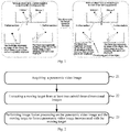
- FIG. 1 a simple schematic diagram is shown in which a moving target is displayed abnormally in the related art.
- a human figure having a certain height is simply shown as a moving target, and the moving target is walking in a preset scene from left to right (the preset scene includes two local spaces where a fisheye camera 1 and a fisheye camera 2 are respectively located).
- the fisheye camera 1 and the fisheye camera 2 respectively collect corresponding video images, and dotted lines indicate boundaries of line of sight for capturing the moving target from the position of respective fisheye cameras.
- a projection of the moving target is located on a floor, as indicated by a bold black line in the figure; in the line of sight of fisheye camera 2, the projection of the moving target is located on a stitching wall, as indicated by a bold black line in the figure.
- the moving target moves to point B, in the line of sight of fisheye camera 1, a part of the projection of the moving target is located on the floor, and a part thereof is located at the stitching position, as indicated by a bold black line in the figure; in the line of sight of fisheye camera 2, the projection of the moving target is located at the stitching position, as indicated by a bold black line in the figure.
- An embodiment of the present application provides a method for fusion of a panoramic video, which can solve a problem that a panoramic video image formed by stitching is incomplete.
- An embodiment of the present application provides an apparatus for fusion of a panoramic video, which can solve a problem that a panoramic video image formed by stitching is incomplete.
- a method for fusion of a panoramic video includes:
- a moving target is extracted from a cuboid three-dimensional image adopted in generating the panoramic video image, and then the moving target is fused into the panoramic video image, thereby a problem of abnormal display of the moving target in the panoramic video image generated by adopting the cuboid three-dimensional model is solved and the completeness of the panoramic video image is ensured.
- extracting the moving target from the at least two cuboid three-dimensional images includes: when it is detected that a moving target is displayed abnormally at a stitching area in the panoramic video image, the moving target is extracted from the at least two cuboid three-dimensional images.
- a moving target displayed abnormally can be specifically extracted, without additional processing on a normally displayed moving target, which improves the efficiency and accuracy of extraction and reduces the complexity of the extraction.
- extracting the moving target from the at least two cuboid three-dimensional images includes:
- determining a target image from a cuboid three-dimensional image corresponding to a stitching area includes:
- determining pixels corresponding to a moving foreground image in the target image includes: performing Gaussian background modeling detection on each pixel in the selected target image by using a Gaussian background modeling algorithm to determine the pixels corresponding to the moving foreground image.
- the selected target image can be detected in real time and stably, which improves the accuracy of acquiring the moving target.
- performing image fusion processing on the panoramic video image and the moving target includes:
- determining color values of pixels in the to-be-fused area of the panoramic video image in which the moving target is inserted by using a Poisson fusion algorithm includes:
- An apparatus for fusion of a panoramic video includes:
- a moving target is extracted from a cuboid three-dimensional image adopted in generating the panoramic video image, and then the moving target is fused into the panoramic video image, thereby a problem of abnormal display of the moving target in the panoramic video image generated by adopting the cuboid three-dimensional model is solved and the completeness of the panoramic video image is ensured.
- the extracting unit is specifically configured for: extracting, when it is detected that a moving target is displayed abnormally at a stitching area in the panoramic video image, the moving target from a cuboid three-dimensional image corresponding to the stitching area.
- the extracting unit is specifically configured for:
- the extracting unit when determining a target image from a cuboid three-dimensional image corresponding to a stitching area, is configured for:
- the extracted unit when determining pixels corresponding to a moving foreground image in the target image, is configured for: performing Gaussian background modeling detection on each pixel in the selected target image by using a Gaussian background modeling algorithm to determine the pixels corresponding to the moving foreground image.
- the selected target image can be detected in real time and stably, which improves the accuracy of acquiring the moving target.
- the fusing unit is specifically configured for:
- the fusing unit when determining color values of pixels in the to-be-fused area of the panoramic video image in which the moving target is inserted by using a Poisson fusion algorithm, is specifically configured for:
- An embodiment of the present application further provides an electronic device suitable for fusion of a panoramic video, the electronic device includes a processor and a memory, wherein the memory is configured for storing executable code, and the processor is configured for performing the following steps by reading the executable code stored in the memory:
- An embodiment of the present application further provides a storage medium, which is configured for storing executable code, and the executable code is configured for executing the method for fusion of a panoramic video according to any of the embodiments of this application when executed.
- the method for fusion of a panoramic video includes:
- An embodiment of the present application further provides a system for fusion of a panoramic video, including at least two panoramic cameras and an image processor, wherein:
- a moving target is extracted from a cuboid three-dimensional image adopted in generating the panoramic video image, and then the moving target is fused into the panoramic video image, thereby a problem of abnormal display of the moving target in the panoramic video image generated by adopting the cuboid three-dimensional model is solved and the completeness of the panoramic video image is ensured.
- the executive body of each step of the method provided in Embodiment 1 may all be the same device, or the method may also be performed by different devices.
- the device may be any device with image processing function, such as an electronic computer, an image processing device, and the like, and may also be a control device of a video monitoring system.
- FIG. 2 is a schematic diagram illustrating steps of a method for fusing panoramic video images provided by Embodiment 1 of the present application, the method mainly includes the following steps.
- Step 21 acquiring a panoramic video image.
- the panoramic video image involved in this step may be formed by stitching cuboid three-dimensional images respectively corresponding to at least two panoramic cameras at different positions in a preset scene.
- the panoramic camera may be a camera having a large angle of view and capable of shooting a specific space in a wide range without a blind angle, and may be, for example, a fisheye camera.
- a fisheye camera For convenience of description, embodiments of the present application are described by taking a fisheye camera as an example, which does not constitute a limitation to the present application.
- a panoramic video image may be generated in the following manner, referring to a flow diagram of steps shown in FIG. 3 .
- Step 31 acquiring a two-dimensional image of each of local spaces in a preset scene captured by a panoramic camera.
- the preset scene may be irregular. For example, there may be a lot of walls and corners in the preset scene, so that the field of view of the preset scene is not wide, and a panorama of the preset scene cannot be captured by shooting at multiple angles or by a single panoramic camera.
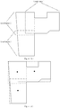
- FIG. 4(a) is a plan top view of a preset scene with an irregular spatial structure provided by Embodiment 1 of the present application. Boundaries of the preset scene are irregular, and there are a lot of walls and corners that block the field of view, and the preset scene is generally "L" shaped.
- Step 31 some preparatory work may be completed by a staff in advance, including measuring size parameters in the preset scene, dividing the local spaces in the preset scene, installing a single fisheye camera in each of the local spaces, and establishing a preset cuboid three-dimensional model of each of local spaces.
- the above preparation work may also be implemented based on machine vision and intelligent algorithms according to a preset measurement rule, division rule, and model establishment rule.
- FIG. 4(a) is a plan top view illustrating the preset scene shown in FIG. 4(a) after division according to the present application. As shown in Fig.
- the preset scene is divided into three local spaces, local space 1 to local space 3 are respectively defined by different dividing lines, wherein, the local space 1 corresponds to a short dashed dividing line, the local space 2 corresponds to a dot-dashed dividing line, the local space 3 corresponds to a long dashed dividing line, and there is an overlapping portion between the three local spaces.
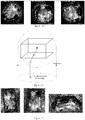
- FIG. 4(c) is a plan top view illustrating cuboid three-dimensional models corresponding to the local spaces in the preset scene shown in FIG. 4(b) according to Embodiment 1 of the present application.
- a large black dot represents a fisheye camera
- boundaries of three preset cuboid three-dimensional models are respectively represented by different lines, and the correspondence is the same as shown in FIG. 4(b) .
- a center of a middle section of each of preset cuboid three-dimensional models in the horizontal direction may be a position of a fisheye camera installed in the corresponding local space
- the preset cuboid three-dimensional model may be a cuboid capable of completely surrounding the corresponding local space.
- the preset cuboid three-dimensional model corresponds to a projection model shown in FIG. 4(e) .
- an original two-dimensional image of each of local spaces captured by the corresponding fisheye camera is a circular two-dimensional plane image.
- FIG. 4(d) illustrates two-dimensional images of three local spaces captured respectively by three fisheye cameras shown in FIG. 4(c) according to the embodiment of the present application.
- Step 32 determining, for each of the local spaces, a cuboid three-dimensional image of the local space according to a two-dimensional image of the local space and a cuboid three-dimensional model corresponding to the local space.
- a projected pixel corresponding to a pixel of a specific number of pixels in the two-dimensional image of the local space is determined by projecting each of the specific number of pixels on the cuboid three-dimensional model corresponding to the local space; and then the cuboid three-dimensional image of the local space is determined according to each of the determined projected pixels.
- the specific number of pixels may be all pixels in the two-dimensional image, and may also be a part of pixels in the two-dimensional image.
- the part of pixels in the two-dimensional image of the local space may be part pixels extracted in a certain interval according to an arrangement order of the pixels.
- FIG. 4(e) is a schematic diagram of a projection model of a fisheye camera provided by the embodiment of the present application. As shown in FIG.
- a center of a circumscribed sphere of the cuboid three-dimensional model corresponding to the local space may be considered as a position at which the fisheye camera is installed; a middle section of the preset cuboid three-dimensional model that is in the horizontal direction and includes the center of the sphere may be considered as the upper surface of the local space; a lower half part of the preset cuboid three-dimensional model may be considered as the local space; and the lower half part of the circumscribed spherical surface may be considered as the visible area of the fisheye camera.
- the visible area of the fisheye camera projects directly below itself to obtain a plane image, that is the original two-dimensional image, wherein, point 1 is a projected pixel on the lower surface of the preset cuboid two-dimensional model of the local space, point 2 is a pixel projected on the spherical surface corresponding to point 1, and point 3 is an original pixel obtained by projecting point 2 on the plane in the vertical direction.
- the embodiment of the present application provides a method for determining a projected pixel corresponding to a pixel projected on a cuboid three-dimensional model corresponding to a local space according to each pixel in a two-dimensional image of the local space.
- the method includes, determining an circumscribed spherical surface of the cuboid three-dimensional model corresponding to the local space, wherein a radius of the circumscribed spherical surface is not greater than a visual distance of the panoramic camera, and the two-dimensional image of the local space is located directly below the cuboid three-dimensional model corresponding to the local space; determining, for each pixel in the two-dimensional image of the local space, a projection of the pixel on the circumscribed spherical surface in a direction perpendicular to the plane of the two-dimensional image as a spherical surface pixel; determining a line connecting the center of the circumscribed spherical surface and the spherical surface pixel; taking an intersection point between the connecting line and a surface of the cuboid three-dimensional model corresponding to the local space as a projected pixel corresponding to the pixel on the cuboid three-dimensional model corresponding to the local space; taking a pixel value (i.e
- FIG. 4(f) illustrates effect diagrams of the generated cuboid three-dimensional images respectively corresponding to the two-dimensional images shown in FIG. 4(d) according to the embodiment of the present application.
- Step 33 generating a panoramic video image of the preset scene according to the determined cuboid three-dimensional image of each local space.
- cuboid three-dimensional images may be arranged according to a relative position of preset cuboid three-dimensional models corresponding to local spaces respectively, and then geometric adjustment is performed at a stitching position between the cuboid three-dimensional images until adjacent cuboid three-dimensional images are completely connected and matched with each other, and then the panoramic video image of the preset scene is obtained.
- FIG. 4(g) is a three-dimensional effect diagram of the panoramic video image of the preset scene generated after stitching each of cuboid three-dimensional images according to the embodiment of the present application.
- a method of obtaining panoramic video images may include, but not limited to, the following two manners.
- Manner 1 receiving a panoramic video image generated by other devices according to the above steps 31-33.
- Manner 2 generating a panoramic video image by itself according to the above steps 31-33.
- the moving target may be extracted from at least two cuboid three-dimensional images involved, and then the moving target is fused into the generated panoramic video image to ensure the integrity of the panoramic video image.
- the stitching area may be determined after generating the panoramic video image. Specifically, a boundary of the stitching area is a stitching position, and the other boundary is a preset base line. For any of the cuboid three-dimensional images, the stitching position in the cuboid three-dimensional image may be determined after generating the panoramic video image. Meanwhile, the position of the preset base line is determined according to a height of the moving target and a capture angle of a fisheye camera. Thereby the stitching area is determined.
- Step 22 extracting a moving target from the at least two cuboid three-dimensional images.
- all moving targets may be extracted from the cuboid three-dimensional images that are stitched to form the panoramic video image, and then fusion processing is performed on the moving target by an image fusion method.
- a moving target may be extracted from at least two cuboid three-dimensional images when it is detected that the moving target displays abnormally at the stitching area in the panoramic video image.
- a moving target displayed abnormally may be extracted, without additional processing on a normally displayed moving target, which improves efficiency and accuracy of extraction on one hand and reduces the complexity of the extraction on the other hand.
- the moving target is displayed abnormally in the stitching area, which may refer to a situation in which the moving target disappears in whole or in part at the stitching area, or an abnormal display such as a ghost is appear.
- the determined panoramic video image may be compared with all cuboid three-dimensional images used in stitching by means of an image comparison manner. If the two do not match, it is determined that a moving target is displayed abnormally in the panoramic video image, and thereby the moving target may be extracted from a corresponding cuboid three-dimensional image.
- extracting a moving target from a cuboid three-dimensional image may be specifically implemented by the following steps.
- Step 401 determining a target image from a cuboid three-dimensional image corresponding to a stitching area.
- a target image used for extracting the moving target may be determined in advance, that is, not only to ensure that the moving target is completely included in the target image, but also to ensure that the extracted moving target is located in the stitching area, so as to avoid extra extraction of other moving target. Therefore, the step 401 may be specifically implemented by the following steps.
- step 1 determining a cuboid three-dimensional image corresponding to the stitching area in which the moving target is located.
- this step in order to reduce a processing complexity and to avoid the extraction of the moving object for all cuboid three-dimensional images, this step defines a processing object as a cuboid three-dimensional image corresponding to the stitching area in which the moving target is located, thereby ensuring the accuracy of the extraction of the moving target.
- step 2 taking a ground image of the determined cuboid three-dimensional image as a target image.
- the preset scene is mainly an indoor scene. Therefore, when there is a moving target, people or animals walking on the ground are usually taken as moving targets. At this time, the ground image in the cuboid three-dimensional image may be taken as a target image. In addition to the moving target walking on the ground, if a flying moving target is also considered, for example an airplane model flying in an indoor scene, then a whole cuboid three-dimensional image may be taken as the target image.
- Step 402 determining pixels corresponding to a moving foreground image in the target image.
- step 402 there are many ways to determine the moving foreground, such as frame difference, moving competition, background subtraction and so on, so as to accurately identify the moving foreground.
- the present application uses Gaussian background modeling algorithm to extract the moving foreground.
- the Gaussian background modeling algorithm mainly converts the moving target detection problem in the background image (ie, the target image in this application) into a two-classification problem based on a background estimation of the currently determined background image. All pixels belonging to the background image are classified into two types: fixed background and moving foreground, and then a classification result is processed to obtain a final detection result.
- Step 402 may be specifically implemented as: performing Gaussian background modeling detection on each pixel in the selected target image by using a Gaussian background modeling algorithm to determine pixels corresponding to the moving foreground image.
- a color value of a pixel in the selected target image is taken as a random function P, assuming that a probability of occurrence of the color value of the pixel obeys a Gaussian distribution, and I ( x , y , t ) represents a color value of a pixel ( x , y ) at time t, a probability density function for any pixel ( x , y ) may be obtained according to the Gaussian background modeling algorithm.
- P I 1 2 ⁇ ⁇ ⁇ I e ⁇ x ⁇ u t 2 2 ⁇ t 2
- u t and ⁇ t are expected value and standard deviation of the Gaussian distribution of the pixel ( x , y ) at time t , respectively
- P(I) represents the color value of the pixel.
- the moving foreground image and the fixed background image may be detected according to the following formula (3):
- I x y t ⁇ 0 , I x y t ⁇ u t ⁇ 1 x y ⁇ ⁇ ⁇ ⁇ t ⁇ 1 x y 1 , I x y t ⁇ u t ⁇ 1 x y ⁇ ⁇ ⁇ ⁇ t ⁇ 1 x y
- pixels corresponding to the desired moving foreground image may be determined in the above manner.
- the Gaussian background modeling algorithm since time is considered in the process of background estimation, the Gaussian background modeling algorithm has high real-time performance and stability, which can improve the accuracy of the detection.
- Step 403 identifying a contour of the moving target according to the determined pixels.
- the contour of the moving target may be identified from the target image according to the pixels.
- the so-called moving target in the embodiment of the present application, is actually a moving object in the preset scene, including: walking or running people, animals, and the like, as well as moving non-organisms such as a chair, an airplane, and the like.
- a moving target in the target image is a walking person
- pixels of the moving foreground are determined according to the Gaussian background modeling algorithm described above, and then the contour of the person is identified by using the pixels to ensure the integrity of the moving target acquired subsequently.
- Step 404 acquiring mask information of an image area corresponding to the contour of the moving target.
- the Gaussian background modeling algorithm is only a background estimation, a contour including a moving target identified from the pixels is not necessarily the contour of the desired moving target. Therefore, it is necessary to acquire mask information of an image area corresponding to the contour of the determined moving target.
- the mask information may be information of a binary image set artificially, and refers to two possible values or gray level states of each of pixels on the image, and people often use black and white (B&W), and monochrome images to represent a binary image. Since the Gaussian background modeling algorithm is used in the present application, the mask information of the moving target may be represented based on the above determined binary value of 0 or 1.
- Step 405 extracting the moving target according to the mask information.
- the desired moving target may be extracted according to the mask information of the image area corresponding to the contour of the moving target. For example, if a mask value of the moving target is 1, pixels corresponding to the mask value 1 are extracted from the mask information and taken as the moving target. In fact, in the specific extraction process, information of a pixel such as a position of the pixel and a color value of the pixel is also used.
- Step 23 performing image fusion processing on the panoramic video image and the moving target, to form a panoramic video image incorporated with the moving target.
- the extracted moving target is fused into a corresponding position in the panoramic video image, and the actual preset scene may be completely presented, and an abnormal display of the moving target at the stitching position and in the vicinity of the stitching position is avoided, and the accuracy and completeness of the panoramic video image are improved.
- a moving target located at a stitching area is extracted from cuboid three-dimensional images used for generating the panoramic video image, and then the moving target is fused into the panoramic video image, thereby a problem of abnormal display of the moving target at the stitching position and in the vicinity of the stitching position in the panoramic video image generated by adopting the cuboid three-dimensional model is solved and the completeness of the panoramic video image is ensured.
- the Gaussian background modeling algorithm is used and it can detect the selected target image in real time and stably, which improves the accuracy of acquiring the moving target.
- Embodiment 2 of the present application provides a method for performing image fusion processing on a panoramic video image and a moving target.
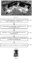
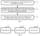
- FIG. 7 is a schematic diagram illustrating steps of a Poisson fusion method according to Embodiment 2 of the present application, the method mainly includes: Step 51: inserting the moving target in a to-be-fused area of the panoramic video image.
- the moving target extracted using the method according to Embodiment 1 is inserted into the to-be-fused area of the panoramic video image by using an interpolation algorithm, so that the moving target is present at the to-be-fused area.
- Step 52 determining color values of pixels in the to-be-fused area of the panoramic video image in which the moving target is inserted by using a Poisson fusion algorithm.
- a divergence of a color value of the panoramic video image in which the moving target is inserted is determined; and a sparse matrix is generated according to a boundary constraint condition of the to-be-fused area of the panoramic video image.
- the calculation of the divergence and sparse matrix may be carried out simultaneously or sequentially.
- the color value of the pixel in the to-be-fused area is determined by solving the above Poisson equation.
- the divergence of the color value of the panoramic video image inserted with the moving target and the sparse matrix involved in this step may be obtained by the following manners.
- the divergence of the color value of the panoramic video image inserted with the moving target is determined by: calculating a gradient field of a video image corresponding to the moving target, calculating a gradient field of a panoramic video image displayed abnormally at the stitching position, and calculating a gradient field of the panoramic video image inserted with the moving target, and then calculating a partial derivative of the gradient of the panoramic video image inserted with the moving target to determine the divergence of the panoramic video image inserted with the moving target.
- the sparse matrix is determined by: determining a divergence of each pixel in the to-be-fused area, wherein the divergence of a pixel at the boundary is obtained by the boundary constraint condition, and the divergence of a pixel outside of the boundary is obtained by summing color values of four pixels, i.e. top, bottom, left, and right pixels of the above pixel, and then the sum subtracting four times of the color value of the pixel to obtain the divergence thereof.
- Step 53 performing image reconstruction on the to-be-fused area according to the determined color values of the pixels.
- each pixel in the to-be-fused area is processed, and image reconstruction is performed on the to-be-fused area, that is, the color value of each of pixels in the to-be-fused area is replaced by a determined color value of a corresponding pixel to achieve the image reconstruction.
- the moving target in the stitching area of the panoramic video image is complete, and the color values of the pixels at the boundary are relatively continuous, thereby realizing natural seamless fusion, improving the fusion effect, and ensuring the quality of the panoramic video image.
- a moving target located at a stitching area is extracted from a cuboid three-dimensional image, and then the moving target is fused into the panoramic video image, thereby a problem of abnormal display of the moving target at the stitching position and in the vicinity of the stitching position in the panoramic video image generated by adopting the cuboid three-dimensional model is solved, in particular, the problem of abnormal display of the moving target is solved, and the completeness of the panoramic video image is ensured.
- the Poisson fusion algorithm is used to fuse the moving target.
- the Poisson fusion algorithm fully considers a color divergence of the image area corresponding to the moving target, and uses the boundary condition as a limit, so that the color value of each pixel in the to-be-fused area can be seamlessly matched with those of pixels in the area outside the to-be-fused area in the panoramic video image, thereby ensuring that the color values of the pixels at the boundary between the image of reconstructed fused area and areas outside of the fused area in the panoramic video image are continuous, realizing seamless fusion, improving the fusion effect and ensuring the quality of the panoramic video image.
- the present application also provides an apparatus for fusion of a panoramic video.
- the apparatus mainly includes the following functional units:
- the extracting unit in order to reduce the complexity of extracting a moving target and improve the accuracy of the extracting operation, is specifically configured for extracting a moving target from a cuboid three-dimensional image corresponding to the stitching area when it is detected that the moving target is displayed abnormally at the stitching area in the panoramic video image.
- the extracting unit when extracting the moving target from the at least two cuboid three-dimensional images, is specifically configured for determining a target image from the cuboid three-dimensional image corresponding to the stitching area, determining pixels corresponding to a moving foreground image in the target image, identifying a contour of the moving target according to the determined pixels, acquiring mask information of an image area corresponding to the contour of the moving target, and extracting the moving target according to the mask information.
- the extracting unit when determining the target image from the cuboid three-dimensional image, is specifically configured for determining a cuboid three-dimensional image corresponding to the stitching area in which the moving target is located, and taking the ground image of the determined cuboid three-dimensional image as the target image.
- the extracting unit when determining the pixels corresponding to the moving foreground image in the target image, is specifically configured for performing Gaussian background modeling detection on each of pixels in the selected target image by using a Gaussian background modeling algorithm, and determining the pixels corresponding to the moving foreground image.
- the fusing unit may be specifically configured for inserting the moving target into a to-be-fused area of the panoramic video image, determining color values of pixels in the to-be-fused area of the panoramic video image infused with the moving target by using a Poisson fusion algorithm, and performing image reconstruction on the to-be-fused area according to the determined color values of the pixels.
- performing the method of the Embodiment 1 or Embodiment 2 by using the apparatus for fusion of a panoramic video can effectively solve the problem that the moving target disappears at the stitching position or in the vicinity of the stitching position in the panoramic video image generated by using the cuboid three-dimensional model.
- the selected target image can be detected in real time and stably, which improves the accuracy of acquiring the moving target, thereby ensuring the completeness of the panoramic video image.
- the Poisson fusion algorithm is used to fuse the moving target, so that the determined color value of each pixel in the fused area can be seamlessly matched with those of the pixels in the area outside the fused area in the panoramic video image, thereby ensuring that the color values of the pixels at the boundary between the image of reconstructed fused area and areas outside of the fused area in the panoramic video image are continuous, realizing natural seamless fusion, improving the fusion effect and ensuring the quality of the panoramic video image.
- An embodiment of the present application further provides an electronic device suitable for fusion of a panoramic video, the electronic device includes a processor and a memory, wherein the memory is configured for storing executable code, and the processor is configured for performing the following steps by reading the executable code stored in the memory:
- the electronic device exists in various forms, including but not limited to:
- a moving target is extracted from a cuboid three-dimensional image adopted in generating the panoramic video image, and then the moving target is fused into the panoramic video image, thereby a problem of abnormal display of the moving target in the panoramic video image generated by adopting the cuboid three-dimensional model is solved and the completeness of the panoramic video image is ensured.
- An embodiment of the present application further provides a storage medium, which is configured for storing executable code, and the executable code is configured for executing the method for fusion of a panoramic video according to any of the embodiments of this application when executed.
- the method for fusion of a panoramic video includes:
- a moving target is extracted from a cuboid three-dimensional image adopted in generating the panoramic video image, and then the moving target is fused into the panoramic video image, thereby a problem of abnormal display of the moving target in the panoramic video image generated by adopting the cuboid three-dimensional model is solved and the completeness of the panoramic video image is ensured.
- An embodiment of the present application further provide a system for fusion of a panoramic video, including at least two panoramic cameras and an image processor, wherein:
- embodiments of the present application may be provided as a method, system, or computer program product.
- the present application may take the form of an entirely hardware embodiment, an entirely software embodiment or an embodiment in combination of software and hardware.
- the present application may take the form of a computer program product implemented in one or more computer -usable storage media (including but not limited to a disk storage, CD-ROM, optical storage, etc.) including computer usable program code.
- each flow and/or block in a flow diagram and/or block diagram, as well as a combination of the flows and/or blocks in the flow diagram and/or block diagram may be implemented by computer program instructions.
- These computer program instructions may be provided to processors of general purpose computers, special purpose computers, embedded processors or other programmable data processing devices to generate a machine, so that an apparatus for implementing a function specified in one or more flows of the flow diagram and/or one or more blocks of the block diagram is generated by instructions executed by a computer or a processor of other programmable data processing device.
- These computer instructions may also be stored in a computer readable memory which can guide a computer or other programmable data processing device to work in a specific way, so that instructions stored in the computer readable memory can generate a manufacture including an instruction apparatus that implements a function specified in one or more flows of the flow diagram and/or one or more blocks of the block diagram.
- These computer instructions may also be loaded onto a computer or other programmable data processing device, so that a series of operational steps are performed on the computer or other programmable device to generate computer-implemented processing, thereby instructions executed on a computer or other programmable device provide a step for implementing a function specified in one or more flows of the flow diagram and/or one or more blocks of the block diagram.
- a computing device comprises one or more processors (CPU), input/output interfaces, network interfaces and a memory.
- the memory may include a volatile memory, random access memory (RAM), and/or non-volatile memory in a computer readable medium, such as a read-only memory (ROM) or flash random access memory (flash RAM).
- RAM random access memory
- ROM read-only memory
- flash RAM flash random access memory
- Memory is an example of a computer readable medium.
- Computer readable media include permanent and non-permanent, removable and non-removable media that can achieve information storage by any method or technology.
- the information may be computer readable instructions, data structures, modules of programs, or other data.
- the examples of the computer storage media includes, but not limited to, phase change random access memory (PRAM), static random access memory (SRAM), dynamic random access memory (DRAM), other types of random access memory (RAM), read-only memory(ROM), electrically erasable programmable read-only memory (EEPROM), flash memory or other memory technology, compact disk read only memory (CD-ROM), digital versatile disk (DVD) or other optical storages, magnetic cassette tape, magnetic tape disk storage or other magnetic storage devices or any other non-transmittable media that can be configured to store the information that can be accessed by a computing device.
- the computer readable media does not include transitory media, such as modulated data signals and carrier waves.
Landscapes
- Engineering & Computer Science (AREA)
- Physics & Mathematics (AREA)
- General Physics & Mathematics (AREA)
- Theoretical Computer Science (AREA)
- Computer Vision & Pattern Recognition (AREA)
- Multimedia (AREA)
- Image Analysis (AREA)
- Closed-Circuit Television Systems (AREA)
- Studio Devices (AREA)
- Image Processing (AREA)
Applications Claiming Priority (2)
| Application Number | Priority Date | Filing Date | Title |
|---|---|---|---|
| CN201611176064.2A CN108205797B (zh) | 2016-12-16 | 2016-12-16 | 一种全景视频融合方法及装置 |
| PCT/CN2017/107988 WO2018107910A1 (zh) | 2016-12-16 | 2017-10-27 | 一种全景视频融合方法及装置 |
Publications (2)
| Publication Number | Publication Date |
|---|---|
| EP3557522A1 true EP3557522A1 (de) | 2019-10-23 |
| EP3557522A4 EP3557522A4 (de) | 2019-12-04 |
Family
ID=62557935
Family Applications (1)
| Application Number | Title | Priority Date | Filing Date |
|---|---|---|---|
| EP17880174.2A Ceased EP3557522A4 (de) | 2016-12-16 | 2017-10-27 | Verfahren und vorrichtung zur fusion von panoramavideobildern |
Country Status (4)
| Country | Link |
|---|---|
| US (1) | US10991072B2 (de) |
| EP (1) | EP3557522A4 (de) |
| CN (1) | CN108205797B (de) |
| WO (1) | WO2018107910A1 (de) |
Cited By (1)
| Publication number | Priority date | Publication date | Assignee | Title |
|---|---|---|---|---|
| CN115293994A (zh) * | 2022-09-30 | 2022-11-04 | 腾讯科技(深圳)有限公司 | 图像处理方法、装置、计算机设备和存储介质 |
Families Citing this family (47)
| Publication number | Priority date | Publication date | Assignee | Title |
|---|---|---|---|---|
| KR102330264B1 (ko) * | 2017-08-04 | 2021-11-23 | 삼성전자주식회사 | 움직임 정보에 기반하여 동영상을 재생하기 위한 장치 및 그의 동작 방법 |
| CN108683842B (zh) * | 2018-04-25 | 2021-06-04 | 影石创新科技股份有限公司 | 一种全景相机及输出全景视频的方法和装置 |
| CN108965859B (zh) * | 2018-07-09 | 2020-05-22 | 歌尔科技有限公司 | 投影方式识别方法、视频播放方法、装置及电子设备 |
| CN111757146B (zh) * | 2019-03-29 | 2022-11-15 | 杭州萤石软件有限公司 | 视频拼接的方法、系统及存储介质 |
| CN110555818B (zh) * | 2019-09-09 | 2022-02-18 | 中国科学院遥感与数字地球研究所 | 一种卫星图像序列云区修补方法和装置 |
| CN111091516B (zh) * | 2019-12-24 | 2021-06-04 | 广州柏视医疗科技有限公司 | 一种基于人工智能的抗散射光栅方法及装置 |
| CN111325665A (zh) * | 2020-04-07 | 2020-06-23 | 同创蓝天投资管理(北京)有限公司 | 基于网络全景图的视频轻量嵌入方法 |
| CN112055192B (zh) * | 2020-08-04 | 2022-10-11 | 北京城市网邻信息技术有限公司 | 图像处理方法、图像处理装置、电子设备及存储介质 |
| CN114143528B (zh) * | 2020-09-04 | 2024-06-28 | 北京大视景科技有限公司 | 多视频流融合方法、电子设备、存储介质 |
| CN112017222B (zh) * | 2020-09-08 | 2024-08-02 | 北京正安维视科技股份有限公司 | 视频全景拼接与三维融合方法及装置 |
| CN112163996B (zh) * | 2020-09-10 | 2023-12-05 | 沈阳风驰软件股份有限公司 | 一种基于图像处理的平角视频融合方法 |
| CN112085659B (zh) * | 2020-09-11 | 2023-01-06 | 中德(珠海)人工智能研究院有限公司 | 一种基于球幕相机的全景拼接融合方法、系统及存储介质 |
| CN112258437A (zh) * | 2020-10-22 | 2021-01-22 | 广东电网有限责任公司 | 一种投影图像融合方法、装置、设备和存储介质 |
| CN112200727B (zh) * | 2020-11-06 | 2023-11-21 | 星宸科技股份有限公司 | 图像缝合装置、图像处理芯片、及图像缝合方法 |
| CN112257657B (zh) * | 2020-11-11 | 2024-02-27 | 网易(杭州)网络有限公司 | 脸部图像融合方法及装置、存储介质、电子设备 |
| CN112488995B (zh) * | 2020-11-18 | 2023-12-12 | 成都主导软件技术有限公司 | 列车自动化检修的智能判伤方法及系统 |
| CN112884844B (zh) * | 2021-01-13 | 2023-02-03 | 深圳市豪恩汽车电子装备股份有限公司 | 全景影像系统的标定方法、装置及计算机可读存储介质 |
| CN112767484B (zh) * | 2021-01-25 | 2023-09-05 | 脸萌有限公司 | 定位模型的融合方法、定位方法、电子装置 |
| CN113012302B (zh) * | 2021-03-02 | 2024-07-12 | 北京爱笔科技有限公司 | 三维全景图生成方法、装置、计算机设备和存储介质 |
| US11210844B1 (en) | 2021-04-13 | 2021-12-28 | Dapper Labs Inc. | System and method for creating, managing, and displaying 3D digital collectibles |
| US11099709B1 (en) | 2021-04-13 | 2021-08-24 | Dapper Labs Inc. | System and method for creating, managing, and displaying an interactive display for 3D digital collectibles |
| USD991271S1 (en) | 2021-04-30 | 2023-07-04 | Dapper Labs, Inc. | Display screen with an animated graphical user interface |
| US11227010B1 (en) | 2021-05-03 | 2022-01-18 | Dapper Labs Inc. | System and method for creating, managing, and displaying user owned collections of 3D digital collectibles |
| US11533467B2 (en) * | 2021-05-04 | 2022-12-20 | Dapper Labs, Inc. | System and method for creating, managing, and displaying 3D digital collectibles with overlay display elements and surrounding structure display elements |
| US11170582B1 (en) | 2021-05-04 | 2021-11-09 | Dapper Labs Inc. | System and method for creating, managing, and displaying limited edition, serialized 3D digital collectibles with visual indicators of rarity classifications |
| CN113344787B (zh) * | 2021-06-11 | 2022-02-01 | 北京中交华安科技有限公司 | 最佳缝合线自动调整算法、交通预警方法及系统 |
| CN113360797B (zh) * | 2021-06-22 | 2023-12-15 | 北京百度网讯科技有限公司 | 信息处理方法、装置、设备、存储介质及计算机程序产品 |
| CN113610869A (zh) * | 2021-08-06 | 2021-11-05 | 成都易瞳科技有限公司 | 基于gis系统的全景监控显示方法 |
| CN115797164B (zh) * | 2021-09-09 | 2023-12-12 | 同方威视技术股份有限公司 | 固定视场中的图像拼接方法、装置、系统 |
| CN113902610B (zh) * | 2021-10-09 | 2025-01-28 | 中国科学院空天信息创新研究院 | 一种面向遥感图像的数据增广方法、装置及电子设备 |
| US11763497B2 (en) * | 2021-10-19 | 2023-09-19 | Toyota Motor Engineering & Manufacturing North America, Inc. | Methods and systems for generating simulated datasets for fisheye camera applications |
| CN114007044B (zh) * | 2021-10-28 | 2025-01-21 | 安徽奇智科技有限公司 | 一种基于opencv的图像拼接系统及方法 |
| CN114545963A (zh) * | 2021-12-20 | 2022-05-27 | 北京理工大学 | 一种优化多无人机全景监控视频的方法、系统及电子设备 |
| CN114612613B (zh) * | 2022-03-07 | 2022-11-29 | 北京拙河科技有限公司 | 动态光场重建方法及系统 |
| CN114648476B (zh) * | 2022-03-15 | 2025-12-16 | 中国科学院深圳先进技术研究院 | 一种基于视频前景提取的视频融合方法及装置 |
| CN115396644B (zh) * | 2022-07-21 | 2023-09-15 | 贝壳找房(北京)科技有限公司 | 基于多段外参数据的视频融合方法及装置 |
| CN115908694A (zh) * | 2022-09-22 | 2023-04-04 | 阿里巴巴(中国)有限公司 | 视频生成方法、信息显示方法及计算设备 |
| CN115861070A (zh) * | 2022-12-14 | 2023-03-28 | 湖南凝服信息科技有限公司 | 一种三维视频融合拼接方法 |
| CN116630174B (zh) * | 2023-03-13 | 2025-11-25 | 四川国创新视超高清视频科技有限公司 | 一种多视频全景拼接的色差矫正方法、系统、电子设备 |
| CN116684682A (zh) * | 2023-04-21 | 2023-09-01 | 海纳云物联科技有限公司 | 视频处理方法、装置、设备及存储介质 |
| CN116311087B (zh) * | 2023-05-23 | 2023-08-08 | 深圳市鑫莱达安防技术有限公司 | 基于摄像机组的监控方法、装置、设备及存储介质 |
| CN116567166B (zh) * | 2023-07-07 | 2023-10-17 | 广东省电信规划设计院有限公司 | 一种视频融合方法、装置、电子设备及存储介质 |
| CN116778170B (zh) * | 2023-08-25 | 2023-11-07 | 安徽蔚来智驾科技有限公司 | 点云全景分割方法、控制装置、可读存储介质及车辆 |
| CN116824641B (zh) * | 2023-08-29 | 2024-01-09 | 卡奥斯工业智能研究院(青岛)有限公司 | 姿态分类方法、装置、设备和计算机存储介质 |
| CN117746513B (zh) * | 2024-02-19 | 2024-04-30 | 成都体育学院 | 基于视频运动目标检测与融合的运动技术教学方法及系统 |
| CN118587399B (zh) * | 2024-07-23 | 2024-11-15 | 杭州萤石软件有限公司 | 一种三维视频融合方法、装置及电子设备 |
| CN120163492B (zh) * | 2025-03-02 | 2026-02-27 | 上海新建设工程咨询有限公司 | 一种基于ai大模型的工程质量管理方法及系统 |
Family Cites Families (16)
| Publication number | Priority date | Publication date | Assignee | Title |
|---|---|---|---|---|
| FR2821167B1 (fr) * | 2001-02-16 | 2003-12-05 | Immervision Internat Pte Ltd | Dispositif support d'appareil photographique |
| CN101146231A (zh) * | 2007-07-03 | 2008-03-19 | 浙江大学 | 根据多视角视频流生成全景视频的方法 |
| CN101577795A (zh) * | 2009-06-17 | 2009-11-11 | 深圳华为通信技术有限公司 | 一种实现全景图像的实时预览的方法和装置 |
| US9317133B2 (en) * | 2010-10-08 | 2016-04-19 | Nokia Technologies Oy | Method and apparatus for generating augmented reality content |
| US9088714B2 (en) * | 2011-05-17 | 2015-07-21 | Apple Inc. | Intelligent image blending for panoramic photography |
| CN102426705B (zh) * | 2011-09-30 | 2013-10-30 | 北京航空航天大学 | 一种视频场景行为拼接方法 |
| US10848731B2 (en) * | 2012-02-24 | 2020-11-24 | Matterport, Inc. | Capturing and aligning panoramic image and depth data |
| US9832378B2 (en) * | 2013-06-06 | 2017-11-28 | Apple Inc. | Exposure mapping and dynamic thresholding for blending of multiple images using floating exposure |
| US9158985B2 (en) * | 2014-03-03 | 2015-10-13 | Xerox Corporation | Method and apparatus for processing image of scene of interest |
| US9563953B2 (en) * | 2014-08-28 | 2017-02-07 | Qualcomm Incorporated | Systems and methods for determining a seam |
| CN104639911B (zh) * | 2015-02-09 | 2018-04-27 | 浙江宇视科技有限公司 | 一种全景视频拼接方法及装置 |
| WO2016165016A1 (en) * | 2015-04-14 | 2016-10-20 | Magor Communications Corporation | View synthesis-panorama |
| CN105046649A (zh) * | 2015-06-30 | 2015-11-11 | 硅革科技(北京)有限公司 | 一种去除运动视频中运动物体的全景图拼接方法 |
| US9699380B2 (en) * | 2015-11-03 | 2017-07-04 | Intel Corporation | Fusion of panoramic background images using color and depth data |
| US20170243384A1 (en) * | 2016-02-19 | 2017-08-24 | Mediatek Inc. | Image data processing system and associated methods for processing panorama images and image blending using the same |
| US10368067B2 (en) * | 2016-06-15 | 2019-07-30 | Mediatek Inc. | Method and apparatus for selective filtering of cubic-face frames |
-
2016
- 2016-12-16 CN CN201611176064.2A patent/CN108205797B/zh active Active
-
2017
- 2017-10-27 WO PCT/CN2017/107988 patent/WO2018107910A1/zh not_active Ceased
- 2017-10-27 EP EP17880174.2A patent/EP3557522A4/de not_active Ceased
- 2017-10-27 US US16/469,747 patent/US10991072B2/en active Active
Cited By (1)
| Publication number | Priority date | Publication date | Assignee | Title |
|---|---|---|---|---|
| CN115293994A (zh) * | 2022-09-30 | 2022-11-04 | 腾讯科技(深圳)有限公司 | 图像处理方法、装置、计算机设备和存储介质 |
Also Published As
| Publication number | Publication date |
|---|---|
| CN108205797A (zh) | 2018-06-26 |
| EP3557522A4 (de) | 2019-12-04 |
| WO2018107910A1 (zh) | 2018-06-21 |
| US10991072B2 (en) | 2021-04-27 |
| US20200090303A1 (en) | 2020-03-19 |
| CN108205797B (zh) | 2021-05-11 |
Similar Documents
| Publication | Publication Date | Title |
|---|---|---|
| US10991072B2 (en) | Method and device for fusing panoramic video images | |
| US11330172B2 (en) | Panoramic image generating method and apparatus | |
| US11393173B2 (en) | Mobile augmented reality system | |
| CN113196296B (zh) | 使用几何上下文检测人群中的对象 | |
| CN110427917B (zh) | 用于检测关键点的方法和装置 | |
| US20230419438A1 (en) | Extraction of standardized images from a single-view or multi-view capture | |
| US10950032B2 (en) | Object capture coverage evaluation | |
| EP3001384B1 (de) | Vorrichtung zur berechnung dreidimensionaler koordinaten, verfahren zur berechnung dreidimensionaler koordinaten und programm zur berechnung dreidimensionaler koordinaten | |
| US20200387718A1 (en) | System and method for counting objects | |
| CN113705669A (zh) | 一种数据匹配方法、装置、电子设备以及存储介质 | |
| US9361731B2 (en) | Method and apparatus for displaying video on 3D map | |
| US20220078385A1 (en) | Projection method based on augmented reality technology and projection equipment | |
| CN109035330A (zh) | 箱体拟合方法、设备和计算机可读存储介质 | |
| CN113298708B (zh) | 三维房型的生成方法、装置及设备 | |
| CN117197388B (zh) | 一种基于生成对抗神经网络和倾斜摄影的实景三维虚拟现实场景构建方法及系统 | |
| US20240261677A1 (en) | Determination method, determination apparatus of calibration information and electronic device | |
| CN111325107A (zh) | 检测模型训练方法、装置、电子设备和可读存储介质 | |
| CN109716386A (zh) | 利用多个相机获得最佳球形影像的方法 | |
| JP6240706B2 (ja) | グラフマッチングおよびサイクル検出による自動モデル初期化を用いた線トラッキング | |
| CN114445458B (zh) | 目标跟踪方法、装置、电子设备及存储介质 | |
| CN109816791B (zh) | 用于生成信息的方法和装置 | |
| CN115527074B (zh) | 一种车辆检测框的生成方法、生成装置及计算机设备 | |
| CN118052929A (zh) | 模型重建方法、装置、电子设备及可读存储介质 | |
| KR20170108552A (ko) | 수변구조물 피해정보 분석을 위한 정보시스템 구축방안 | |
| CN112651351A (zh) | 一种数据处理的方法和装置 |
Legal Events
| Date | Code | Title | Description |
|---|---|---|---|
| STAA | Information on the status of an ep patent application or granted ep patent |
Free format text: STATUS: THE INTERNATIONAL PUBLICATION HAS BEEN MADE |
|
| PUAI | Public reference made under article 153(3) epc to a published international application that has entered the european phase |
Free format text: ORIGINAL CODE: 0009012 |
|
| STAA | Information on the status of an ep patent application or granted ep patent |
Free format text: STATUS: REQUEST FOR EXAMINATION WAS MADE |
|
| 17P | Request for examination filed |
Effective date: 20190708 |
|
| AK | Designated contracting states |
Kind code of ref document: A1 Designated state(s): AL AT BE BG CH CY CZ DE DK EE ES FI FR GB GR HR HU IE IS IT LI LT LU LV MC MK MT NL NO PL PT RO RS SE SI SK SM TR |
|
| AX | Request for extension of the european patent |
Extension state: BA ME |
|
| A4 | Supplementary search report drawn up and despatched |
Effective date: 20191106 |
|
| RIC1 | Information provided on ipc code assigned before grant |
Ipc: G06T 11/00 20060101ALI20191030BHEP Ipc: G06T 7/194 20170101ALI20191030BHEP Ipc: G06T 3/40 20060101AFI20191030BHEP |
|
| DAV | Request for validation of the european patent (deleted) | ||
| DAX | Request for extension of the european patent (deleted) | ||
| STAA | Information on the status of an ep patent application or granted ep patent |
Free format text: STATUS: EXAMINATION IS IN PROGRESS |
|
| 17Q | First examination report despatched |
Effective date: 20210518 |
|
| REG | Reference to a national code |
Ref country code: DE Ref legal event code: R003 |
|
| STAA | Information on the status of an ep patent application or granted ep patent |
Free format text: STATUS: THE APPLICATION HAS BEEN REFUSED |
|
| 18R | Application refused |
Effective date: 20231121 |