EP3557267A1 - Multi-clamp measurement device and current measurement system - Google Patents
Multi-clamp measurement device and current measurement system Download PDFInfo
- Publication number
- EP3557267A1 EP3557267A1 EP17881511.4A EP17881511A EP3557267A1 EP 3557267 A1 EP3557267 A1 EP 3557267A1 EP 17881511 A EP17881511 A EP 17881511A EP 3557267 A1 EP3557267 A1 EP 3557267A1
- Authority
- EP
- European Patent Office
- Prior art keywords
- magnetic field
- current
- conductor
- clamp
- magnetic
- Prior art date
- Legal status (The legal status is an assumption and is not a legal conclusion. Google has not performed a legal analysis and makes no representation as to the accuracy of the status listed.)
- Withdrawn
Links
- 238000005259 measurement Methods 0.000 title claims abstract description 103
- 239000004020 conductor Substances 0.000 claims abstract description 83
- 238000010586 diagram Methods 0.000 description 14
- 230000007423 decrease Effects 0.000 description 2
- 238000000034 method Methods 0.000 description 2
- 230000000903 blocking effect Effects 0.000 description 1
- 238000004364 calculation method Methods 0.000 description 1
- 230000000694 effects Effects 0.000 description 1
- 230000005684 electric field Effects 0.000 description 1
- 238000005516 engineering process Methods 0.000 description 1
- 230000014509 gene expression Effects 0.000 description 1
- 230000006698 induction Effects 0.000 description 1
- 239000000463 material Substances 0.000 description 1
- 230000035699 permeability Effects 0.000 description 1
- 238000004804 winding Methods 0.000 description 1
Images


Classifications
-
- G—PHYSICS
- G01—MEASURING; TESTING
- G01R—MEASURING ELECTRIC VARIABLES; MEASURING MAGNETIC VARIABLES
- G01R15/00—Details of measuring arrangements of the types provided for in groups G01R17/00 - G01R29/00, G01R33/00 - G01R33/26 or G01R35/00
- G01R15/14—Adaptations providing voltage or current isolation, e.g. for high-voltage or high-current networks
- G01R15/20—Adaptations providing voltage or current isolation, e.g. for high-voltage or high-current networks using galvano-magnetic devices, e.g. Hall-effect devices, i.e. measuring a magnetic field via the interaction between a current and a magnetic field, e.g. magneto resistive or Hall effect devices
- G01R15/207—Constructional details independent of the type of device used
-
- G—PHYSICS
- G01—MEASURING; TESTING
- G01R—MEASURING ELECTRIC VARIABLES; MEASURING MAGNETIC VARIABLES
- G01R15/00—Details of measuring arrangements of the types provided for in groups G01R17/00 - G01R29/00, G01R33/00 - G01R33/26 or G01R35/00
- G01R15/14—Adaptations providing voltage or current isolation, e.g. for high-voltage or high-current networks
- G01R15/18—Adaptations providing voltage or current isolation, e.g. for high-voltage or high-current networks using inductive devices, e.g. transformers
- G01R15/186—Adaptations providing voltage or current isolation, e.g. for high-voltage or high-current networks using inductive devices, e.g. transformers using current transformers with a core consisting of two or more parts, e.g. clamp-on type
-
- G—PHYSICS
- G01—MEASURING; TESTING
- G01R—MEASURING ELECTRIC VARIABLES; MEASURING MAGNETIC VARIABLES
- G01R15/00—Details of measuring arrangements of the types provided for in groups G01R17/00 - G01R29/00, G01R33/00 - G01R33/26 or G01R35/00
- G01R15/14—Adaptations providing voltage or current isolation, e.g. for high-voltage or high-current networks
- G01R15/18—Adaptations providing voltage or current isolation, e.g. for high-voltage or high-current networks using inductive devices, e.g. transformers
-
- G—PHYSICS
- G01—MEASURING; TESTING
- G01R—MEASURING ELECTRIC VARIABLES; MEASURING MAGNETIC VARIABLES
- G01R15/00—Details of measuring arrangements of the types provided for in groups G01R17/00 - G01R29/00, G01R33/00 - G01R33/26 or G01R35/00
- G01R15/14—Adaptations providing voltage or current isolation, e.g. for high-voltage or high-current networks
- G01R15/18—Adaptations providing voltage or current isolation, e.g. for high-voltage or high-current networks using inductive devices, e.g. transformers
- G01R15/183—Adaptations providing voltage or current isolation, e.g. for high-voltage or high-current networks using inductive devices, e.g. transformers using transformers with a magnetic core
-
- G—PHYSICS
- G01—MEASURING; TESTING
- G01R—MEASURING ELECTRIC VARIABLES; MEASURING MAGNETIC VARIABLES
- G01R15/00—Details of measuring arrangements of the types provided for in groups G01R17/00 - G01R29/00, G01R33/00 - G01R33/26 or G01R35/00
- G01R15/14—Adaptations providing voltage or current isolation, e.g. for high-voltage or high-current networks
- G01R15/20—Adaptations providing voltage or current isolation, e.g. for high-voltage or high-current networks using galvano-magnetic devices, e.g. Hall-effect devices, i.e. measuring a magnetic field via the interaction between a current and a magnetic field, e.g. magneto resistive or Hall effect devices
- G01R15/202—Adaptations providing voltage or current isolation, e.g. for high-voltage or high-current networks using galvano-magnetic devices, e.g. Hall-effect devices, i.e. measuring a magnetic field via the interaction between a current and a magnetic field, e.g. magneto resistive or Hall effect devices using Hall-effect devices
Definitions
- the inventive concept relates to a current measurement apparatus, and more particularly, relates to a multi-clamp measurement apparatus and a current measurement system.
- An electrical measurement apparatus is a measurement apparatus that measures various characteristics (e.g., a voltage, a current, and a resistance) of electrical elements or electrical devices. In general, various characteristics of electrical elements or electrical devices are detected by directly attaching the measurement apparatus to the electrical elements or the electrical devices.
- a current that is provided to an electrical element or an electrical device is measured by cutting an electrical wire (or a conductor) providing the current to the electrical element or the electrical device and connecting a measurement apparatus with the electrical wire thus cut.
- a clamp-type measurement apparatus that measures an electric field (or a magnetic field) generated by a current flowing through the electrical wire is being used.
- the clamp-type measurement apparatus does not directly measure a current of an electrical wire but estimates a current based on a magnetic field around the electrical wire, the clamp-type measurement apparatus has a significant influence of a magnetic field by an external factor, and thus, the accuracy of measurement of the current decreases.
- the inventive concept is for solving the above problem, and an object of the inventive concept provides a multi-clamp measurement apparatus and a current measurement system, which have improving reliability and reduced costs.
- a multi-clamp measurement apparatus includes a multi-clamp including first and second cores configured to detect first and second magnetic fields around a conductor, respectively, and a current measurement controller configured to remove a noise magnetic field around the conductor based on the first and second magnetic fields and to detect a current flowing through the conductor.
- each of the first and second magnetic fields includes a component of a current magnetic field generated by the current flowing through the conductor and a component of the noise magnetic field.
- the first core includes a first magnetic sensor measuring the first magnetic field
- the second core includes a second magnetic sensor measuring the second magnetic field
- the first and second magnetic sensors have a geometric position difference of 180 degrees mutually with respect to the conductor.
- a magnitude of the first magnetic field is a sum of a magnetic field of the current magnetic field and a magnitude of the noise magnetic field
- a magnitude of the second magnetic field is a difference between the magnitude of the current magnetic field and the magnitude of the noise magnetic field.
- the first and second magnetic sensors are disposed at different positions with respect to the conductor, and the current measurement controller is configured to detect the current by performing a vector operation on the first and second magnetic fields such that the noise magnetic field is removed.
- the noise magnetic field includes at least one a magnetic field existing in a natural state, a magnetic field generated by another conductor, or a magnetic field generated by another device.
- the first and second cores are disposed adjacent to each other and are spaced from each other as much as a given distance along the conductor.
- the first and second cores are embedded in one case.
- a multi-clamp measurement apparatus includes a multi-clamp including a plurality of cores configured to detect magnetic fields around a conductor, respectively, and a current measurement controller configured to remove a noise magnetic field around the conductor based on the plurality of magnetic fields and to detect a current flowing through the conductor.
- each of the plurality of magnetic fields includes a component of a current magnetic field generated by the current flowing through the conductor and a component of the noise magnetic field.
- a current measurement system includes a first current measurement apparatus configured to measure a first magnetic field around a conductor, a second current measurement apparatus spaced from the first current measurement apparatus as much as a given distance, and configured to measure a second magnetic field around the conductor, and a current measurement controller configured to remove a noise magnetic field around the conductor based on the first and second magnetic fields and to detect a current flowing through the conductor.
- a micro-current flowing through a conductor may be accurately measured without a separate shielding device.
- a multi-clamp measurement apparatus according to the inventive concept may be used for various tests of various electric devices such as an electric motor and an electric generator, thus improving the reliability of a test result. Accordingly, a multi-clamp measurement apparatus having improved reliability and reduced costs is provided.
- FIG. 1 A drawing showing the best mode for carrying out the inventive concept is FIG. 1 .
- FIG. 1 is a diagram illustrating a multi-clamp measurement apparatus according to an embodiment of the inventive concept.
- a multi-clamp measurement apparatus 100 includes a multi-clamp 110 and a current measurement controller 120.
- the multi-clamp 110 may be coupled with an outer surface of a conductor ML and may be configured to detect a magnetic field Bi generated by a current flowing through the conductor ML. For example, as illustrated in FIG. 1 , when a current "I" flows through the conductor ML, the magnetic field Bi may be generated by the current "I" around the conductor ML.
- the multi-clamp 110 may have a structure (e.g., a clamp-type structure) to wrap around the conductor ML.
- a core included in the multi-clamp 110 may detect a magnitude of a magnetic field that is generated around the conductor ML or exists around the conductor ML.
- a core may be formed of a material of great permeability for the purpose of detecting a magnetic field easily.
- a magnetic field may be detected through a separate magnetic field sensor such as a hall sensor.
- a magnetic field may be detected by using a magnetic induction phenomenon through a winding wire wound on a core.
- a magnetic field that is generated by the current "I" flowing through the conductor ML is called a "current magnetic field".
- the current measurement controller 120 may detect a magnitude of the current "I” flowing through the conductor ML, based on a magnitude of the current magnetic field Bi detected from the multi-clamp 110.
- a magnitude of the magnetic field Bi is proportional to a magnitude of the current "I” and is inversely proportional to a distance from the conductor ML. That is, when a magnitude of a magnetic field around the conductor ML is detected, the current measurement controller 120 may detect the magnitude of the current "I” based on the distance from the conductor ML.
- an unintended magnetic field Bn may be generated around the conductor ML.
- the unintended magnetic field Bn that is not a magnetic field generated by the current "I" flowing through the conductor ML may include a magnetic field existing in a natural state, a magnetic field generated by any other conductor, or a magnetic field generated by any other surrounding factors.
- the unintended magnetic field Bn is called a "noise magnetic field”.
- the noise magnetic field Bn may be combined with a magnetic field generated by the current "I", and the multi-clamp 110 may detect the combined magnetic field. In this case, a magnitude of the current "I" flowing through the conductor ML may not be accurately detected due to the noise magnetic field Bn.
- a magnitude of the current magnetic field Bi when a large current "I" (e.g., tens or hundreds mA, several to tens A, or the like) flows through the conductor ML, because a magnitude of the current magnetic field Bi is significantly greater than the noise magnetic field Bn, an error of a measured current magnitude due to the noise magnetic field Bn may be ignored.
- a magnitude of a current flowing through the conductor ML is small (i.e., a micro-current flows through the conductor ML)
- a magnitude of the current magnetic field Bi may be smaller than a magnitude of the noise magnetic field Bn, or the magnitude of the noise magnetic field Bn may be great to such an extent as not to be ignored, compared with the magnitude of the magnetic field Bi generated by the current "I". In this case, the magnitude of the current "I" flowing through the conductor ML may not be accurately measured.
- Conventional current measurement apparatuses include a separate shielding device for blocking the noise magnetic field Bn for the purpose of measuring a micro-current.
- the shielding device is problematic in that the attachment to the conductor ML is difficult and costs of the measurement apparatuses increase.
- the multi-clamp measurement apparatus 100 may accurately measure a micro-current "I" flowing through the conductor ML without a separate shielding device.
- the multi-clamp 110 includes a first core 111 and a second core 112.
- the first and second cores 111 and 112 may be configured to detect a magnetic field around the conductor ML.
- each of first and second magnetic fields B1 and B2 detected through the first and second cores 111 and 112 may include the current magnetic field Bi and the noise magnetic field Bn.
- a component of the current magnetic field Bi included in the first magnetic field B1 and a component of the current magnetic field Bi included in the second magnetic field B2 may have different directivity.
- the current measurement controller 120 may detect only a component of the current magnetic field Bi by removing the noise magnetic field Bn based on the first and second magnetic fields B1 and B2.
- a configuration and a magnetic field detecting scheme of the multi-clamp 110 will be more fully described with reference to the following drawings.
- the multi-clamp measurement apparatus 100 may accurately detect a component of the current magnetic field Bi by detecting magnetic fields around the conductor ML through at least two cores (e.g., 111 and 112) and removing a component of the noise magnetic field Bn based on the detected magnetic fields. Accordingly, the multi-clamp measurement apparatus 100 according to the inventive concept may accurately measure a micro-current "I" flowing through the conductor ML without a separate shielding device.
- FIGS. 2 and 3 are diagrams illustrating a multi-clamp of FIG. 1 in detail.
- the first and second cores 111 and 112 included in the multi-clamp 110 are schematically illustrated.
- a configuration of the multi-clamp 110 or the first and second cores 111 and 112 according to the inventive concept is not limited to a configuration or a shape illustrated in FIGS. 2 and 3 .
- components that are unnecessary to describe a configuration of the multi-clamp 110 according to the inventive concept are omitted.
- the current magnetic field Bi and the noise magnetic field Bn may be expressed by a vector value having directivity.
- the directivity is not described in detail, and a configuration of the inventive concept is described simply with reference to a magnitude of a magnetic field.
- the current magnetic field Bi, the noise magnetic field Bn, or similar other components may actually have directivity and may be obtained through a vector operation.
- first and second magnetic sensors 111a and 112a measure a magnetic field and output the measured magnetic field.
- to output the measured magnetic field means to output a value corresponding to the measured magnetic field.
- the current measurement controller 120 detects a current based on the measured magnetic fields means that the current measurement controller 120 calculates or draws a magnitude of the current "I" flowing through the conductor ML based on actually measured magnetic fields.
- the multi-clamp 110 may include the first and second cores 111 and 112. Each of the first and second cores 111 and 112 may be configured to detect a magnetic field around the conductor ML.
- the first and second cores 111 and 112 may be arranged in a third direction.
- a first section of FIG. 3 shows the first and second cores 111 and 112 projected on a plane defined by a first direction and the third direction.
- the first and second cores 111 and 112 may be spaced from each other as much as a given distance "d" in the third direction.
- the given distance "d" may be several or tens millimeters (mm).
- the noise magnetic field Bn (e.g., a magnitude and a direction of the noise magnetic field Bn) having an influence on the first core 111 may be substantially equal to the noise magnetic field Bn having an influence on the second core 112.
- the first core 111 may include the first magnetic sensor 111a.
- the first magnetic sensor 111a may detect a first magnetic field B1 being a combined magnetic field of the current magnetic field Bi and the noise magnetic field Bn through the first core 111.
- the second core 112 may include the second magnetic sensor 112a.
- the second magnetic sensor 112a may detect a second magnetic field B2 being a combined magnetic field of the current magnetic field Bi and the noise magnetic field Bn through the second core 112.
- the first and second magnetic fields B1 and B2 may have different values depending on positions of the first and second magnetic sensors 111a and 112a.
- the current "I" flows through the conductor ML in a direction opposite to the third direction.
- the current magnetic field Bi may be generated around the conductor ML in a clockwise direction.
- the noise magnetic field Bn has a directivity corresponding to the second direction.
- the first magnetic sensor 111a may be positioned on the left (in detail, on the left of the plane defined by the first and second directions) of the first core 111.
- the current magnetic field Bi and the noise magnetic field Bn may have directivity corresponding to the second direction.
- the first magnetic sensor 111a may have directivity corresponding to the second direction. That is, the first magnetic sensor 111a may be configured to detect a magnitude of a magnetic field generated in the second direction.
- the first magnetic field B1 detected by the first magnetic sensor 111a may be expressed by a sum (i.e., Bi + Bn) of the current magnetic field Bi and the noise magnetic field Bn.
- the second magnetic sensor 112a may be positioned on the right (in detail, on the right of the plane defined by the first and second directions) of the second core 112.
- the current magnetic field Bi may have directivity corresponding to a direction facing away from the second direction
- the noise magnetic field Bn may have directivity corresponding to the second direction.
- the second magnetic sensor 112a may have directivity corresponding to the direction facing away from the second direction. That is, the second magnetic sensor 112a may be configured to detect a magnitude of a magnetic field generated in the direction facing away from the second direction. In this case, the second magnetic field B2 detected by the second magnetic sensor 112a may be expressed by a difference (i.e., Bi - Bn) of the current magnetic field Bi and the noise magnetic field Bn.
- the first magnetic sensor 111a of the first core 111 and the second magnetic sensor 112a of the second core 112 may have a position difference of 180 degrees geometrically mutually with respect to the conductor ML.
- the first magnetic sensor 111a of the first core 111 may be positioned to face an opposite surface of the second magnetic sensor 112a of the second core 112 with respect to the conductor ML (or the sensors 111a and 112a are positioned to face each other).
- the first and second magnetic sensors 111a and 112a may be respectively positioned in air gaps or slits of the first and second cores 111 and 112. That is, the air gaps or slits of the first and second cores 111 and 112 may be formed to have a position difference of 180 degrees geometrically. In an embodiment, the positions of the first and second cores 111 and 112 or the air gaps or slits may be relative positions, not absolute positions.
- the current measurement controller 120 may extract only a component of the current magnetic field Bi based on the first and second magnetic fields B1 and B2 thus measured.
- B i B 1 + B 2 2
- “Bi” represents a current magnetic field
- “B1” represents a magnetic field detected by the first magnetic sensor 111a of the first core 111
- “B2” represents a magnetic field detected by the second magnetic sensor 112a of the second core 112.
- the first magnetic field B1 may be expressed by the sum (Bi + Bn) of the current magnetic field Bi and the noise magnetic field Bn
- the second magnetic field B2 may be expressed by the difference (Bi - Bn) of the current magnetic field Bi and the noise magnetic field Bn.
- a component of the noise magnetic field Bn may be removed through Equation 1 based on the first and second magnetic fields B1 and B2, and only a component of the current magnetic field Bi may be extracted.
- the current measurement controller 120 may detect the current "I" (i.e., a micro-current) flowing through the conductor ML, based on the component of the current magnetic field Bi.
- the multi-clamp measurement apparatus 100 may detect the first and second magnetic fields B1 and B2 through the first and second cores 111 and 112 that are positioned adjacent to each other and may remove the noise magnetic field Bn based on the first and second magnetic fields B1 and B2 thus detected. Accordingly, the micro-current "I" flowing through the conductor ML may be accurately measured.
- FIG. 4 is a diagram for describing a multi-clamp according to another embodiment of the inventive concept. Components that are unnecessary to describe the configuration of a multi-clamp are omitted for a brief description.
- the multi-clamp 110 may include the first and second cores 111 and 112'.
- the first and second cores 111 and 112' include first and second magnetic sensors 111a and 112a'.
- the first and second cores 111 and 112' and the first and second magnetic sensors 111a and 112a' are described with reference to FIGS. 2 and 3 , and thus, additional description will be omitted to avoid redundancy.
- the second magnetic sensor 112a' may not have a position difference of 180 degrees geometrically with the first magnetic sensor 111a.
- the first and second magnetic sensors 111a and 112a described with reference to FIG. 3 have a position difference of 180 degrees geometrically.
- the noise magnetic field Bn may be removed through the method (i.e., a simple scalar operation) described with reference to Equation 1.
- the second magnetic sensor 112a' may have an angle difference of ⁇ geometrically with the second magnetic sensor 112a illustrated in FIG. 3 .
- a direction of the current magnetic field Bi in a region where the second magnetic sensor 112a' of FIG. 4 is positioned may be different from a direction of the current magnetic field Bi in a region where the second magnetic sensor 112a of FIG. 3 is positioned.
- each of the first and second magnetic sensors 111a and 112a' illustrated in FIG. 4 may be configured to detect a direction of a magnetic field as well as a magnitude of the magnetic field. That is, the first and second magnetic sensors 111a and 112a' may be configured to measure a vector value of a magnetic field.
- each of the first and second magnetic sensors 111a and 112a' may include a first sub sensor detecting a magnetic field associated with the first direction, a second sub sensor detecting a magnetic field associated with the second direction, and a third sub sensor detecting a magnetic field associated with the third direction. That is, the first to third sub sensors may have different directivity, and each of the first and second magnetic sensors 111a and 112a' may detect a magnetic field associated with each of the first to third directions.
- the first magnetic field B1 detected by the first magnetic sensor 111a may be a combined magnetic field of the current magnetic field Bi and the noise magnetic field Bn and may be expressed by a vector value of [x1, y1, z1].
- the second magnetic field B2 detected by the second magnetic sensor 112a' may be a combined magnetic field of the current magnetic field Bi and the noise magnetic field Bn and may be expressed by a vector value of [x2, y2, z2].
- the current measurement controller 120 may extract the current magnetic field Bi by using Equation 2 below.
- B i ⁇ B 1 ⁇ + B 2 ⁇ 2
- B i represents a vector value of a current magnetic field
- B 1 represents a vector value of a first magnetic field
- B 2 represents a vector value of a second magnetic field.
- the current measurement controller 120 may detect the current "I" (i.e., a micro-current) flowing through the conductor ML, based on the current magnetic field Bi from which the noise magnetic field Bn is removed.
- the multi-clamp measurement apparatus 100 may detect the first and second magnetic fields B1 and B2 through the first and second cores 111 and 112' and may remove the noise magnetic field Bn based on the first and second magnetic fields B1 and B2 thus detected.
- the noise magnetic field Bn may be removed based on the vector operation.
- the current measurement controller 120 may detect the current "I" (in particular, a micro-current) flowing through the conductor ML, based on the current magnetic field Bi from which the noise magnetic field Bn is removed.
- FIG. 5 is a diagram illustrating a configuration of a multi-clamp according to an embodiment of the inventive concept. For brevity of illustration, a plan view of the multi-clamp 110 projected on a plane defined by the first and second directions of FIG. 2 is illustrated.
- the multi-clamp 110 may include first and second portions 110_1 and 110_2 and a hinge HG.
- Each of the first and second portions 110_1 and 110_2 may include portions of the first and second cores 111 and 112.
- the first portion 110_1 may include a portion of the first core 111 and a portion of the second core 112
- the second portion 110_2 may include the remaining portion of the first core 111 and the remaining portion of the second core 112.
- the hinge HG may allow the first and second portions 110_1 and 110_2 of the multi-clamp 110 to move independently of each other.
- the first and second portions 110_1 and 110_2 of the multi-clamp 110 may move with respect to the hinge HG. That is, as illustrated in FIG. 5 , the multi-clamp 110 may be mounted on the conductor ML (or to surround the conductor ML) in a state where one ends of the first and second portions 110_1 and 110_2 are separated from each other, and may then perform the above current measuring operation as the first and second portions 110_1 and 110_2 are interconnected (in detail, as illustrated in FIG. 2 , such that the multi-clamp 110 wraps around the conductor ML). That is, the multi-clamp 110 may be implemented to be similar to a general clamp meter and may be coupled with the conductor ML without cutting the conductor ML.
- the multi-clamp 110 may be implemented in the form of a circle as illustrated in FIG. 5 .
- the inventive concept is not limited thereto.
- the multi-clamp 110 may be implemented in various shapes that allow a conductive line to be positioned therein (e.g., in the shape of a rectangle, an oval, or a polygon).
- air gaps or slits where the first and second magnetic sensors 111a and 112a are positioned are not clearly illustrated in FIG. 5 , but the first and second magnetic sensors 111a and 112a or the air gaps or slits may be disposed at different positions of the first and second portions 110_1 and 110_2.
- the multi-clamp 110 is illustrated in FIG. 5 as one module, but the inventive concept is not limited thereto.
- the first and second cores 111 and 112 may be implemented with one module. That is, the first and second cores 111 and 112 may be embedded in the same case to implement one module.
- the first and second cores 111 and 112 may be implemented with different modules. That is, the first and second cores 111 and 112 may be respectively embedded in different cases to implement different modules. In the latter case, the first and second cores 111 and 112 may include hinges disposed at different positions, respectively.
- the above configuration of the multi-clamp 110 and the first and second cores 111 and 112 is for describing an embodiment of the inventive concept easily, and the inventive concept is not limited thereto.
- FIGS. 6 and 7 are diagrams illustrating a configuration of a multi-clamp according to an embodiment of the inventive concept.
- a multi-clamp 210 may include first to fourth cores 211 to 214.
- the first to fourth cores 211 to 214 may detect first to fourth magnetic fields B1 to B4 as described with reference to FIGS. 1 to 4 .
- the conductor ML may extend in the third direction
- the current "I" may flow in a direction facing away from the third direction
- the noise magnetic field Bn has directivity of the second direction.
- each of the first to fourth cores 211 to 214 may be configured as illustrated in FIG. 7 .
- the first core 211 may include a first magnetic sensor 211a, and the first magnetic sensor 211a may be positioned on the left of the first core 211 (in detail, on the left of a plane defined by the first and second directions).
- the second core 212 may include a second magnetic sensor 212a, and the second magnetic sensor 212a may be positioned on the top of the second core 212 (in detail, on the top of the plane defined by the first and second directions).
- the third core 213 may include a third magnetic sensor 213a, and the third magnetic sensor 213a may be positioned on the right of the third core 213 (in detail, on the right of the plane defined by the first and second directions).
- the fourth core 214 may include a fourth magnetic sensor 214a, and the fourth magnetic sensor 214a may be positioned on the bottom of the fourth core 214 (in detail, on the bottom of the plane defined by the first and second directions).
- the first to fourth magnetic sensors 211a to 214a may be disposed to have a difference of 90 degrees geometrically mutually.
- the first to fourth magnetic sensors 211a to 214a may have a difference of 90 degrees geometrically mutually, but the inventive concept is not limited thereto.
- the first to fourth magnetic sensors 211a to 214a may be disposed at different positions geometrically, and a geometrical position difference is not limited to 90 degrees.
- each of the first to fourth magnetic sensors 211a to 214a may be configured to detect the current magnetic field Bi and the noise magnetic field Bn. That is, each of the first to fourth magnetic fields B1 to B4 detected from the first to fourth magnetic sensors 211a to 214a may include the current magnetic field Bi and the noise magnetic field Bn according to a location of each of the first to fourth magnetic sensors 211a to 214a.
- each of the first to fourth magnetic fields B1 to B4 detected from the first and second magnetic sensors 211a to 214a may have a vector value having directivity.
- the current measurement controller 120 (refer to FIG. 1 ) may extract only a component of the current magnetic field Bi by performing a vector operation on the first to fourth magnetic fields B1 to B4 being a vector value such that a component of the noise magnetic field Bn is removed.
- a vector operation for removing the noise magnetic field Bn is performed in various manners. Accordingly, to prevent the technical idea of the inventive concept from being ambiguous, a description associated with the vector operation is omitted.
- a multi-clamp measurement apparatus may detect a plurality of magnetic fields through a plurality of cores and may remove a component of the noise magnetic field Bn due to an external factor through a vector operation for the detected magnetic fields. Accordingly, even though a micro-current flows through the conductor ML, because the noise magnetic field Bn is removed, the micro-current may be accurately measured. Also, because a multi-clamp measurement apparatus according to the inventive concept measures a micro-current without a separate shielding device, costs for current measurement decreases.
- FIG. 8 is a block diagram illustrating a multi-clamp measurement apparatus according to the inventive concept.
- a multi-clamp measurement apparatus 300 includes a multi-clamp 310 and a current measurement controller 320.
- the multi-clamp 310 may include first to n-th cores 311 to 31n.
- the first to n-th cores 311 to 31n may be similar to cores described with reference to FIGS. 1 to 7 in structure.
- the first to n-th cores 311 to 31n may include magnetic sensors for detecting magnetic fields, respectively; the magnetic sensors may be disposed at different positions geometrically. Geometric positions of the magnetic sensors are similar to those described with reference to FIGS. 1 to 7 , and thus, additional description will be omitted to avoid redundancy.
- the first to n-th cores 311 to 31n may detect first to n-th magnetic fields B1 to Bn, respectively.
- the current measurement controller 320 may be configured to detect the current magnetic field Bi by performing an operation (e.g., a scalar operation or a vector operation) on the first to n-th magnetic fields B1 to Bn such that the noise magnetic field Bn is removed.
- the current measurement controller 320 may calculate a magnetic field B01 based on the first and second magnetic fields B1 and B2 from the first and second cores 311 and 312 adjacent to each other, the current measurement controller 320 may calculate a magnetic field B02 based on the third and fourth magnetic fields B3 and B4 from the third and fourth cores 313 and 314 adjacent to each other, and the current measurement controller 320 may calculate a magnetic field B0k based on the (n-1)-th and n-th magnetic fields Bn-1 and Bn from the (n-1)-th and n-th cores 31n-1 and 31n adjacent to each other.
- the calculated magnetic fields B01 to B0k may include only a component of the current magnetic field Bi.
- the current measurement controller 320 may calculate a final current magnetic field Bi based on an average of the calculated magnetic fields B01 to B0k and may draw the current "I" based on the final current magnetic field Bi thus calculated.
- the above-described calculation method may be simply an embodiment of the inventive concept and may be changed or modified in various manners.
- the current measurement controller 320 may be configured to remove the noise magnetic field Bn based on at least three adjacent cores.
- a multi-clamp measurement apparatus may include a plurality of cores and may remove the noise magnetic field Bn based on magnetic fields from the plurality of cores. Accordingly, it is possible to measure a micro-current without a separate shielding device.
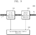
- FIG. 9 is a block diagram illustrating current measurement system according to an embodiment of the inventive concept.
- a current measurement system 1000 may include first and second current measurement apparatuses 1100 and 1200 and a current measurement control apparatus 1300.
- each of the first and second current measurement apparatuses 1100 and 1200 may be a multi-clamp measurement apparatus described with reference to FIGS. 1 to 8 .
- the first and second current measurement apparatuses 1100 and 1200 may be a conventional clamp-type current meter (e.g., a current meter including a single core).
- the first and second current measurement apparatuses 1100 and 1200 may be disposed adjacent to each other and may be mounted on the conductor ML.
- the first and second current measurement apparatuses 1100 and 1200 may be configured to output the first and second magnetic fields B1 and B2, respectively.
- the current measurement control apparatus 1300 may detect the current magnetic field Bi by removing the noise magnetic field Bn through an operation for the first and second magnetic fields B1 and B2 and may detect the current "I" flowing through the conductor ML based on the detected current magnetic field Bi.
- a component of the noise magnetic field Bn may be removed by disposing conventional clamp-type current measurement apparatuses to be adjacent to each other and performing an operation on magnetic fields respectively detected from the conventional clamp-type current measurement apparatuses.
- a micro-current flowing through a conductor may be accurately measured without a separate shielding device by applying the technical idea of the inventive concept to the conventional clamp-type current measurement apparatuses.
- a multi-clamp measurement apparatus may accurately measure a micro-current flowing through a conductor by removing a component of the noise magnetic field Bn without a separate shielding device. Accordingly, a multi-clamp measurement apparatus having improved reliability and reduced costs is provided.
- the inventive concept relates a current measurement apparatus, and more particularly, provides a multi-clamp measurement apparatus and a current measurement apparatus.
Landscapes
- Engineering & Computer Science (AREA)
- Power Engineering (AREA)
- Physics & Mathematics (AREA)
- General Physics & Mathematics (AREA)
- Measuring Instrument Details And Bridges, And Automatic Balancing Devices (AREA)
Abstract
Description
- The inventive concept relates to a current measurement apparatus, and more particularly, relates to a multi-clamp measurement apparatus and a current measurement system.
- An electrical measurement apparatus is a measurement apparatus that measures various characteristics (e.g., a voltage, a current, and a resistance) of electrical elements or electrical devices. In general, various characteristics of electrical elements or electrical devices are detected by directly attaching the measurement apparatus to the electrical elements or the electrical devices.
- For example, a current that is provided to an electrical element or an electrical device is measured by cutting an electrical wire (or a conductor) providing the current to the electrical element or the electrical device and connecting a measurement apparatus with the electrical wire thus cut. To solve the issue such as the cutting of an electrical wire, a clamp-type measurement apparatus that measures an electric field (or a magnetic field) generated by a current flowing through the electrical wire is being used.
- However, because the clamp-type measurement apparatus does not directly measure a current of an electrical wire but estimates a current based on a magnetic field around the electrical wire, the clamp-type measurement apparatus has a significant influence of a magnetic field by an external factor, and thus, the accuracy of measurement of the current decreases.
- The inventive concept is for solving the above problem, and an object of the inventive concept provides a multi-clamp measurement apparatus and a current measurement system, which have improving reliability and reduced costs.
- A multi-clamp measurement apparatus according to an embodiment of the inventive concept includes a multi-clamp including first and second cores configured to detect first and second magnetic fields around a conductor, respectively, and a current measurement controller configured to remove a noise magnetic field around the conductor based on the first and second magnetic fields and to detect a current flowing through the conductor.
- As an embodiment, each of the first and second magnetic fields includes a component of a current magnetic field generated by the current flowing through the conductor and a component of the noise magnetic field.
- As an embodiment, the first core includes a first magnetic sensor measuring the first magnetic field, and the second core includes a second magnetic sensor measuring the second magnetic field.
- As an embodiment, the first and second magnetic sensors have a geometric position difference of 180 degrees mutually with respect to the conductor.
- As an embodiment, a magnitude of the first magnetic field is a sum of a magnetic field of the current magnetic field and a magnitude of the noise magnetic field, and a magnitude of the second magnetic field is a difference between the magnitude of the current magnetic field and the magnitude of the noise magnetic field.
- As an embodiment, the first and second magnetic sensors are disposed at different positions with respect to the conductor, and the current measurement controller is configured to detect the current by performing a vector operation on the first and second magnetic fields such that the noise magnetic field is removed.
- As an embodiment, the noise magnetic field includes at least one a magnetic field existing in a natural state, a magnetic field generated by another conductor, or a magnetic field generated by another device.
- As an embodiment, the first and second cores are disposed adjacent to each other and are spaced from each other as much as a given distance along the conductor.
- As an embodiment, the first and second cores are embedded in one case.
- A multi-clamp measurement apparatus according to the inventive concept includes a multi-clamp including a plurality of cores configured to detect magnetic fields around a conductor, respectively, and a current measurement controller configured to remove a noise magnetic field around the conductor based on the plurality of magnetic fields and to detect a current flowing through the conductor.
- As an embodiment, each of the plurality of magnetic fields includes a component of a current magnetic field generated by the current flowing through the conductor and a component of the noise magnetic field.
- A current measurement system according to an embodiment of the inventive concept includes a first current measurement apparatus configured to measure a first magnetic field around a conductor, a second current measurement apparatus spaced from the first current measurement apparatus as much as a given distance, and configured to measure a second magnetic field around the conductor, and a current measurement controller configured to remove a noise magnetic field around the conductor based on the first and second magnetic fields and to detect a current flowing through the conductor.
- According to the inventive concept, a micro-current flowing through a conductor may be accurately measured without a separate shielding device. A multi-clamp measurement apparatus according to the inventive concept may be used for various tests of various electric devices such as an electric motor and an electric generator, thus improving the reliability of a test result. Accordingly, a multi-clamp measurement apparatus having improved reliability and reduced costs is provided.
-
-
FIG. 1 is a diagram illustrating a multi-clamp measurement apparatus according to an embodiment of the inventive concept. -
FIGS. 2 and3 are diagrams illustrating a multi-clamp ofFIG. 1 in detail. -
FIG. 4 is a diagram for describing a multi-clamp according to another embodiment of the inventive concept. -
FIG. 5 is a diagram illustrating a configuration of a multi-clamp according to an embodiment of the inventive concept. -
FIGS. 6 and7 are diagrams illustrating a configuration of a multi-clamp according to an embodiment of the inventive concept. -
FIG. 8 is a block diagram illustrating a multi-clamp measurement apparatus according to the inventive concept. -
FIG. 9 is a block diagram illustrating current measurement system according to an embodiment of the inventive concept. - A drawing showing the best mode for carrying out the inventive concept is
FIG. 1 . - Below, embodiments of the inventive concept may be described in detail and clearly to such an extent that an ordinary one in the art easily implements the inventive concept.
-
FIG. 1 is a diagram illustrating a multi-clamp measurement apparatus according to an embodiment of the inventive concept. Referring toFIG. 1 , amulti-clamp measurement apparatus 100 includes a multi-clamp 110 and acurrent measurement controller 120. - The multi-clamp 110 may be coupled with an outer surface of a conductor ML and may be configured to detect a magnetic field Bi generated by a current flowing through the conductor ML. For example, as illustrated in
FIG. 1 , when a current "I" flows through the conductor ML, the magnetic field Bi may be generated by the current "I" around the conductor ML. The multi-clamp 110 may have a structure (e.g., a clamp-type structure) to wrap around the conductor ML. - A core included in the multi-clamp 110 may detect a magnitude of a magnetic field that is generated around the conductor ML or exists around the conductor ML. In an embodiment, a core may be formed of a material of great permeability for the purpose of detecting a magnetic field easily. In an embodiment, a magnetic field may be detected through a separate magnetic field sensor such as a hall sensor. Alternatively, a magnetic field may be detected by using a magnetic induction phenomenon through a winding wire wound on a core. Below, for convenience of description, a magnetic field that is generated by the current "I" flowing through the conductor ML is called a "current magnetic field".
- The
current measurement controller 120 may detect a magnitude of the current "I" flowing through the conductor ML, based on a magnitude of the current magnetic field Bi detected from the multi-clamp 110. For example, in an ideal case, a magnitude of the magnetic field Bi is proportional to a magnitude of the current "I" and is inversely proportional to a distance from the conductor ML. That is, when a magnitude of a magnetic field around the conductor ML is detected, thecurrent measurement controller 120 may detect the magnitude of the current "I" based on the distance from the conductor ML. - In an embodiment, an unintended magnetic field Bn may be generated around the conductor ML. The unintended magnetic field Bn that is not a magnetic field generated by the current "I" flowing through the conductor ML may include a magnetic field existing in a natural state, a magnetic field generated by any other conductor, or a magnetic field generated by any other surrounding factors. Below, the unintended magnetic field Bn is called a "noise magnetic field". The noise magnetic field Bn may be combined with a magnetic field generated by the current "I", and the multi-clamp 110 may detect the combined magnetic field. In this case, a magnitude of the current "I" flowing through the conductor ML may not be accurately detected due to the noise magnetic field Bn.
- In an embodiment, when a large current "I" (e.g., tens or hundreds mA, several to tens A, or the like) flows through the conductor ML, because a magnitude of the current magnetic field Bi is significantly greater than the noise magnetic field Bn, an error of a measured current magnitude due to the noise magnetic field Bn may be ignored. However, when a magnitude of a current flowing through the conductor ML is small (i.e., a micro-current flows through the conductor ML), a magnitude of the current magnetic field Bi may be smaller than a magnitude of the noise magnetic field Bn, or the magnitude of the noise magnetic field Bn may be great to such an extent as not to be ignored, compared with the magnitude of the magnetic field Bi generated by the current "I". In this case, the magnitude of the current "I" flowing through the conductor ML may not be accurately measured.
- Conventional current measurement apparatuses include a separate shielding device for blocking the noise magnetic field Bn for the purpose of measuring a micro-current. The shielding device is problematic in that the attachment to the conductor ML is difficult and costs of the measurement apparatuses increase.
- The
multi-clamp measurement apparatus 100 according to the inventive concept may accurately measure a micro-current "I" flowing through the conductor ML without a separate shielding device. For example, the multi-clamp 110 includes afirst core 111 and asecond core 112. The first andsecond cores second cores current measurement controller 120 may detect only a component of the current magnetic field Bi by removing the noise magnetic field Bn based on the first and second magnetic fields B1 and B2. A configuration and a magnetic field detecting scheme of the multi-clamp 110 will be more fully described with reference to the following drawings. - As described above, the
multi-clamp measurement apparatus 100 according to the inventive concept may accurately detect a component of the current magnetic field Bi by detecting magnetic fields around the conductor ML through at least two cores (e.g., 111 and 112) and removing a component of the noise magnetic field Bn based on the detected magnetic fields. Accordingly, themulti-clamp measurement apparatus 100 according to the inventive concept may accurately measure a micro-current "I" flowing through the conductor ML without a separate shielding device. -
FIGS. 2 and3 are diagrams illustrating a multi-clamp ofFIG. 1 in detail. For brevity of illustration, the first andsecond cores second cores FIGS. 2 and3 . Also, for brevity of illustration, components that are unnecessary to describe a configuration of the multi-clamp 110 according to the inventive concept are omitted. - In an embodiment, the current magnetic field Bi and the noise magnetic field Bn may be expressed by a vector value having directivity. However, below, for convenience of description, with regard to the current magnetic field Bi and the noise magnetic field Bn, the directivity is not described in detail, and a configuration of the inventive concept is described simply with reference to a magnitude of a magnetic field. However, this is for convenience of description, and the current magnetic field Bi, the noise magnetic field Bn, or similar other components may actually have directivity and may be obtained through a vector operation.
- Below, for convenience of description, a description will be given as the multi-clamp 110, the first and
second cores magnetic sensors current measurement controller 120 detects a current based on the measured magnetic fields means that thecurrent measurement controller 120 calculates or draws a magnitude of the current "I" flowing through the conductor ML based on actually measured magnetic fields. The terms and expressions that are described below are for describing an embodiment of the inventive concept easily, and it may be well understood that an actual implementation manner is variously changed or modified. - Referring to
FIGS. 1 and2 , the multi-clamp 110 may include the first andsecond cores second cores - The first and
second cores FIG. 3 shows the first andsecond cores FIG. 3 , the first andsecond cores second cores second cores first core 111 may be substantially equal to the noise magnetic field Bn having an influence on thesecond core 112. - The
first core 111 may include the firstmagnetic sensor 111a. The firstmagnetic sensor 111a may detect a first magnetic field B1 being a combined magnetic field of the current magnetic field Bi and the noise magnetic field Bn through thefirst core 111. Thesecond core 112 may include the secondmagnetic sensor 112a. The secondmagnetic sensor 112a may detect a second magnetic field B2 being a combined magnetic field of the current magnetic field Bi and the noise magnetic field Bn through thesecond core 112. - In an embodiment, the first and second magnetic fields B1 and B2 may have different values depending on positions of the first and second
magnetic sensors - As illustrated in a second section of
FIG. 3 , the firstmagnetic sensor 111a may be positioned on the left (in detail, on the left of the plane defined by the first and second directions) of thefirst core 111. At the position of the firstmagnetic sensor 111a, the current magnetic field Bi and the noise magnetic field Bn may have directivity corresponding to the second direction. - The first
magnetic sensor 111a may have directivity corresponding to the second direction. That is, the firstmagnetic sensor 111a may be configured to detect a magnitude of a magnetic field generated in the second direction. In this case, the first magnetic field B1 detected by the firstmagnetic sensor 111a may be expressed by a sum (i.e., Bi + Bn) of the current magnetic field Bi and the noise magnetic field Bn. - As illustrated in a third section of
FIG. 3 , the secondmagnetic sensor 112a may be positioned on the right (in detail, on the right of the plane defined by the first and second directions) of thesecond core 112. At the position of the secondmagnetic sensor 112a, the current magnetic field Bi may have directivity corresponding to a direction facing away from the second direction, and the noise magnetic field Bn may have directivity corresponding to the second direction. - The second
magnetic sensor 112a may have directivity corresponding to the direction facing away from the second direction. That is, the secondmagnetic sensor 112a may be configured to detect a magnitude of a magnetic field generated in the direction facing away from the second direction. In this case, the second magnetic field B2 detected by the secondmagnetic sensor 112a may be expressed by a difference (i.e., Bi - Bn) of the current magnetic field Bi and the noise magnetic field Bn. - As described above, the first
magnetic sensor 111a of thefirst core 111 and the secondmagnetic sensor 112a of thesecond core 112 may have a position difference of 180 degrees geometrically mutually with respect to the conductor ML. In other words, the firstmagnetic sensor 111a of thefirst core 111 may be positioned to face an opposite surface of the secondmagnetic sensor 112a of thesecond core 112 with respect to the conductor ML (or thesensors - In an embodiment, the first and second
magnetic sensors second cores second cores second cores - According to
Equation 1 below, thecurrent measurement controller 120 may extract only a component of the current magnetic field Bi based on the first and second magnetic fields B1 and B2 thus measured.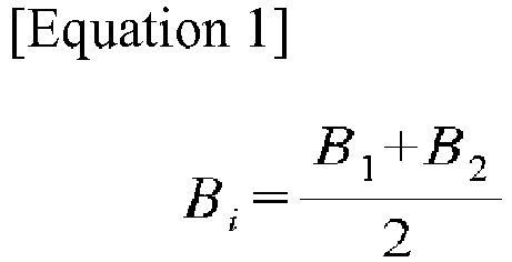
InEquation 1, "Bi" represents a current magnetic field, "B1" represents a magnetic field detected by the firstmagnetic sensor 111a of thefirst core 111, and "B2" represents a magnetic field detected by the secondmagnetic sensor 112a of thesecond core 112. As described above, the first magnetic field B1 may be expressed by the sum (Bi + Bn) of the current magnetic field Bi and the noise magnetic field Bn, and the second magnetic field B2 may be expressed by the difference (Bi - Bn) of the current magnetic field Bi and the noise magnetic field Bn. Accordingly, a component of the noise magnetic field Bn may be removed throughEquation 1 based on the first and second magnetic fields B1 and B2, and only a component of the current magnetic field Bi may be extracted. Thecurrent measurement controller 120 may detect the current "I" (i.e., a micro-current) flowing through the conductor ML, based on the component of the current magnetic field Bi. - As described above, the
multi-clamp measurement apparatus 100 according to the inventive concept may detect the first and second magnetic fields B1 and B2 through the first andsecond cores -
FIG. 4 is a diagram for describing a multi-clamp according to another embodiment of the inventive concept. Components that are unnecessary to describe the configuration of a multi-clamp are omitted for a brief description. - Referring to
FIGS. 2 and4 , the multi-clamp 110 may include the first andsecond cores 111 and 112'. The first andsecond cores 111 and 112' include first and secondmagnetic sensors second cores 111 and 112' and the first and secondmagnetic sensors FIGS. 2 and3 , and thus, additional description will be omitted to avoid redundancy. - Unlike the
second core 112 ofFIG. 3 , in the second core 112' ofFIG. 4 , the secondmagnetic sensor 112a' may not have a position difference of 180 degrees geometrically with the firstmagnetic sensor 111a. For example, the first and secondmagnetic sensors FIG. 3 have a position difference of 180 degrees geometrically. In this case, the noise magnetic field Bn may be removed through the method (i.e., a simple scalar operation) described with reference toEquation 1. - However, as illustrated in a second section of
FIG. 4 , the secondmagnetic sensor 112a' may have an angle difference of α geometrically with the secondmagnetic sensor 112a illustrated inFIG. 3 . In this case, a direction of the current magnetic field Bi in a region where the secondmagnetic sensor 112a' ofFIG. 4 is positioned may be different from a direction of the current magnetic field Bi in a region where the secondmagnetic sensor 112a ofFIG. 3 is positioned. - In this case, it may be difficult to remove the noise magnetic field Bn based on the method (i.e., a scalar operation) described with reference to
FIG. 3 ; the noise magnetic field Bn of the above case may be removed through a vector operation. For example, each of the first and secondmagnetic sensors FIG. 4 may be configured to detect a direction of a magnetic field as well as a magnitude of the magnetic field. That is, the first and secondmagnetic sensors - In detail, each of the first and second
magnetic sensors magnetic sensors - In this case, the first magnetic field B1 detected by the first
magnetic sensor 111a may be a combined magnetic field of the current magnetic field Bi and the noise magnetic field Bn and may be expressed by a vector value of [x1, y1, z1]. The second magnetic field B2 detected by the secondmagnetic sensor 112a' may be a combined magnetic field of the current magnetic field Bi and the noise magnetic field Bn and may be expressed by a vector value of [x2, y2, z2]. In this case, thecurrent measurement controller 120 may extract the current magnetic field Bi by using Equation 2 below.
- Referring to Equation 2,
Bi represents a vector value of a current magnetic field,B 1 represents a vector value of a first magnetic field,B 2 represents a vector value of a second magnetic field. As described above, because the noise magnetic field Bn is a magnetic field generated by an external factor, the noise magnetic field Bn may have substantially the same direction and substantially the same magnitude, regardless of a position in themulti-clamp 110. That is, the noise magnetic field Bn may be removed through a vector operation of Equation 2. Thecurrent measurement controller 120 may detect the current "I" (i.e., a micro-current) flowing through the conductor ML, based on the current magnetic field Bi from which the noise magnetic field Bn is removed. - As described above, the
multi-clamp measurement apparatus 100 according to the inventive concept may detect the first and second magnetic fields B1 and B2 through the first andsecond cores 111 and 112' and may remove the noise magnetic field Bn based on the first and second magnetic fields B1 and B2 thus detected. In this case, even though the first and secondmagnetic sensors second cores 111 and 112' have not a position difference of 180 degrees geometrically, the noise magnetic field Bn may be removed based on the vector operation. Thecurrent measurement controller 120 may detect the current "I" (in particular, a micro-current) flowing through the conductor ML, based on the current magnetic field Bi from which the noise magnetic field Bn is removed. -
FIG. 5 is a diagram illustrating a configuration of a multi-clamp according to an embodiment of the inventive concept. For brevity of illustration, a plan view of the multi-clamp 110 projected on a plane defined by the first and second directions ofFIG. 2 is illustrated. - Referring to
FIG. 5 , the multi-clamp 110 may include first and second portions 110_1 and 110_2 and a hinge HG. Each of the first and second portions 110_1 and 110_2 may include portions of the first andsecond cores first core 111 and a portion of thesecond core 112, and the second portion 110_2 may include the remaining portion of thefirst core 111 and the remaining portion of thesecond core 112. - The hinge HG may allow the first and second portions 110_1 and 110_2 of the multi-clamp 110 to move independently of each other. For example, the first and second portions 110_1 and 110_2 of the multi-clamp 110 may move with respect to the hinge HG. That is, as illustrated in
FIG. 5 , the multi-clamp 110 may be mounted on the conductor ML (or to surround the conductor ML) in a state where one ends of the first and second portions 110_1 and 110_2 are separated from each other, and may then perform the above current measuring operation as the first and second portions 110_1 and 110_2 are interconnected (in detail, as illustrated inFIG. 2 , such that the multi-clamp 110 wraps around the conductor ML). That is, the multi-clamp 110 may be implemented to be similar to a general clamp meter and may be coupled with the conductor ML without cutting the conductor ML. - In an embodiment, the multi-clamp 110 may be implemented in the form of a circle as illustrated in
FIG. 5 . However, the inventive concept is not limited thereto. For example, the multi-clamp 110 may be implemented in various shapes that allow a conductive line to be positioned therein (e.g., in the shape of a rectangle, an oval, or a polygon). - In an embodiment, air gaps or slits where the first and second
magnetic sensors FIG. 5 , but the first and secondmagnetic sensors - In an embodiment, the multi-clamp 110 is illustrated in
FIG. 5 as one module, but the inventive concept is not limited thereto. For example, as described above, the first andsecond cores second cores second cores second cores second cores - The above configuration of the multi-clamp 110 and the first and
second cores -
FIGS. 6 and7 are diagrams illustrating a configuration of a multi-clamp according to an embodiment of the inventive concept. Referring toFIG. 6 , a multi-clamp 210 may include first tofourth cores 211 to 214. The first tofourth cores 211 to 214 may detect first to fourth magnetic fields B1 to B4 as described with reference toFIGS. 1 to 4 . - For example, as in the description given with reference to
FIG. 2 , it is assumed that the conductor ML may extend in the third direction, the current "I" may flow in a direction facing away from the third direction, and the noise magnetic field Bn has directivity of the second direction. - In this case, each of the first to
fourth cores 211 to 214 may be configured as illustrated inFIG. 7 . For example, thefirst core 211 may include a firstmagnetic sensor 211a, and the firstmagnetic sensor 211a may be positioned on the left of the first core 211 (in detail, on the left of a plane defined by the first and second directions). Thesecond core 212 may include a secondmagnetic sensor 212a, and the secondmagnetic sensor 212a may be positioned on the top of the second core 212 (in detail, on the top of the plane defined by the first and second directions). Thethird core 213 may include a thirdmagnetic sensor 213a, and the thirdmagnetic sensor 213a may be positioned on the right of the third core 213 (in detail, on the right of the plane defined by the first and second directions). Thefourth core 214 may include a fourthmagnetic sensor 214a, and the fourthmagnetic sensor 214a may be positioned on the bottom of the fourth core 214 (in detail, on the bottom of the plane defined by the first and second directions). - In other words, the first to fourth
magnetic sensors 211a to 214a may be disposed to have a difference of 90 degrees geometrically mutually. In an embodiment, the first to fourthmagnetic sensors 211a to 214a may have a difference of 90 degrees geometrically mutually, but the inventive concept is not limited thereto. The first to fourthmagnetic sensors 211a to 214a may be disposed at different positions geometrically, and a geometrical position difference is not limited to 90 degrees. - As in the description given with reference to
FIGS. 2 to 4 , each of the first to fourthmagnetic sensors 211a to 214a may be configured to detect the current magnetic field Bi and the noise magnetic field Bn. That is, each of the first to fourth magnetic fields B1 to B4 detected from the first to fourthmagnetic sensors 211a to 214a may include the current magnetic field Bi and the noise magnetic field Bn according to a location of each of the first to fourthmagnetic sensors 211a to 214a. - In an embodiment, each of the first to fourth magnetic fields B1 to B4 detected from the first and second
magnetic sensors 211a to 214a may have a vector value having directivity. As in the description given with reference toFIG. 4 , the current measurement controller 120 (refer toFIG. 1 ) may extract only a component of the current magnetic field Bi by performing a vector operation on the first to fourth magnetic fields B1 to B4 being a vector value such that a component of the noise magnetic field Bn is removed. - In an embodiment, it may be well understood to one skilled in the art that a vector operation for removing the noise magnetic field Bn is performed in various manners. Accordingly, to prevent the technical idea of the inventive concept from being ambiguous, a description associated with the vector operation is omitted.
- As described above, a multi-clamp measurement apparatus according to the inventive concept may detect a plurality of magnetic fields through a plurality of cores and may remove a component of the noise magnetic field Bn due to an external factor through a vector operation for the detected magnetic fields. Accordingly, even though a micro-current flows through the conductor ML, because the noise magnetic field Bn is removed, the micro-current may be accurately measured. Also, because a multi-clamp measurement apparatus according to the inventive concept measures a micro-current without a separate shielding device, costs for current measurement decreases.
-
FIG. 8 is a block diagram illustrating a multi-clamp measurement apparatus according to the inventive concept. Referring toFIG. 8 , amulti-clamp measurement apparatus 300 includes a multi-clamp 310 and acurrent measurement controller 320. - The multi-clamp 310 may include first to n-
th cores 311 to 31n. The first to n-th cores 311 to 31n may be similar to cores described with reference toFIGS. 1 to 7 in structure. Also, the first to n-th cores 311 to 31n may include magnetic sensors for detecting magnetic fields, respectively; the magnetic sensors may be disposed at different positions geometrically. Geometric positions of the magnetic sensors are similar to those described with reference toFIGS. 1 to 7 , and thus, additional description will be omitted to avoid redundancy. - The first to n-
th cores 311 to 31n may detect first to n-th magnetic fields B1 to Bn, respectively. Thecurrent measurement controller 320 may be configured to detect the current magnetic field Bi by performing an operation (e.g., a scalar operation or a vector operation) on the first to n-th magnetic fields B1 to Bn such that the noise magnetic field Bn is removed. - For example, the
current measurement controller 320 may calculate a magnetic field B01 based on the first and second magnetic fields B1 and B2 from the first andsecond cores current measurement controller 320 may calculate a magnetic field B02 based on the third and fourth magnetic fields B3 and B4 from the third andfourth cores current measurement controller 320 may calculate a magnetic field B0k based on the (n-1)-th and n-th magnetic fields Bn-1 and Bn from the (n-1)-th and n-th cores 31n-1 and 31n adjacent to each other. In an embodiment, the calculated magnetic fields B01 to B0k may include only a component of the current magnetic field Bi. Thecurrent measurement controller 320 may calculate a final current magnetic field Bi based on an average of the calculated magnetic fields B01 to B0k and may draw the current "I" based on the final current magnetic field Bi thus calculated. - In an embodiment, the above-described calculation method may be simply an embodiment of the inventive concept and may be changed or modified in various manners. For example, the
current measurement controller 320 may be configured to remove the noise magnetic field Bn based on at least three adjacent cores. - As described above, a multi-clamp measurement apparatus according to the inventive concept may include a plurality of cores and may remove the noise magnetic field Bn based on magnetic fields from the plurality of cores. Accordingly, it is possible to measure a micro-current without a separate shielding device.
-
FIG. 9 is a block diagram illustrating current measurement system according to an embodiment of the inventive concept. Referring toFIG. 9 , acurrent measurement system 1000 may include first and secondcurrent measurement apparatuses measurement control apparatus 1300. - In an embodiment, each of the first and second
current measurement apparatuses FIGS. 1 to 8 . Alternatively, the first and secondcurrent measurement apparatuses current measurement apparatuses current measurement apparatuses - As described with reference to
FIGS. 1 to 8 , the currentmeasurement control apparatus 1300 may detect the current magnetic field Bi by removing the noise magnetic field Bn through an operation for the first and second magnetic fields B1 and B2 and may detect the current "I" flowing through the conductor ML based on the detected current magnetic field Bi. - That is, a component of the noise magnetic field Bn may be removed by disposing conventional clamp-type current measurement apparatuses to be adjacent to each other and performing an operation on magnetic fields respectively detected from the conventional clamp-type current measurement apparatuses. In other words, a micro-current flowing through a conductor may be accurately measured without a separate shielding device by applying the technical idea of the inventive concept to the conventional clamp-type current measurement apparatuses.
- According to the above embodiments of the inventive concept, a multi-clamp measurement apparatus may accurately measure a micro-current flowing through a conductor by removing a component of the noise magnetic field Bn without a separate shielding device. Accordingly, a multi-clamp measurement apparatus having improved reliability and reduced costs is provided.
- The above-mentioned description refers to embodiments for implementing the scope of the inventive concept. Embodiments in which a design is changed simply or which are easily changed may be included in the scope of the inventive concept as well as an embodiment described above. In addition, technologies that are easily changed and implemented by using the above-mentioned embodiments may be also included in the scope of the inventive concept. Therefore, it should be understood that the above embodiments are not limiting, but illustrative.
- The inventive concept relates a current measurement apparatus, and more particularly, provides a multi-clamp measurement apparatus and a current measurement apparatus.
Claims (12)
- A multi-clamp measurement apparatus comprising:a multi-clamp including first and second cores configured to detect first and second magnetic fields around a conductor, respectively; anda current measurement controller configured to remove a noise magnetic field around the conductor based on the first and second magnetic fields and to detect a current flowing through the conductor.
- The multi-clamp measurement apparatus of claim 1, wherein each of the first and second magnetic fields includes a component of a current magnetic field generated by the current flowing through the conductor and a component of the noise magnetic field.
- The multi-clamp measurement apparatus of claim 2, wherein the first core includes a first magnetic sensor measuring the first magnetic field, and
wherein the second core includes a second magnetic sensor measuring the second magnetic field. - The multi-clamp measurement apparatus of claim 3, wherein the first and second magnetic sensors have a geometric position difference of 180 degrees mutually with respect to the conductor.
- The multi-clamp measurement apparatus of claim 4, wherein a magnitude of the first magnetic field is a sum of a magnetic field of the current magnetic field and a magnitude of the noise magnetic field, and
wherein a magnitude of the second magnetic field is a difference between the magnitude of the current magnetic field and the magnitude of the noise magnetic field. - The multi-clamp measurement apparatus of claim 3, wherein the first and second magnetic sensors are disposed at different positions with respect to the conductor, and
wherein the current measurement controller is configured to detect the current by performing a vector operation on the first and second magnetic fields such that the noise magnetic field is removed. - The multi-clamp measurement apparatus of claim 1, wherein the noise magnetic field includes at least one a magnetic field existing in a natural state, a magnetic field generated by another conductor, or a magnetic field generated by another device.
- The multi-clamp measurement apparatus of claim 1, wherein the first and second cores are disposed adjacent to each other and are spaced from each other as much as a given distance along the conductor.
- The multi-clamp measurement apparatus of claim 1, wherein the first and second cores are embedded in one case.
- A multi-clamp measurement apparatus comprising:a multi-clamp including a plurality of cores configured to detect magnetic fields around a conductor, respectively; anda current measurement controller configured to remove a noise magnetic field around the conductor based on the plurality of magnetic fields and to detect a current flowing through the conductor.
- The multi-clamp measurement apparatus of claim 10, wherein each of the plurality of magnetic fields includes a component of a current magnetic field generated by the current flowing through the conductor and a component of the noise magnetic field.
- A current measurement system comprising:a first current measurement apparatus configured to measure a first magnetic field around a conductor;a second current measurement apparatus spaced from the first current measurement apparatus as much as a given distance, and configured to measure a second magnetic field around the conductor; anda current measurement controller configured to remove a noise magnetic field around the conductor based on the first and second magnetic fields and to detect a current flowing through the conductor.
Applications Claiming Priority (2)
| Application Number | Priority Date | Filing Date | Title |
|---|---|---|---|
| KR1020160170647A KR101931559B1 (en) | 2016-12-14 | 2016-12-14 | Multi-clamp current measuring apparatus and curretn measuring system |
| PCT/KR2017/014694 WO2018110991A1 (en) | 2016-12-14 | 2017-12-14 | Multi-clamp measurement device and current measurement system |
Publications (2)
| Publication Number | Publication Date |
|---|---|
| EP3557267A1 true EP3557267A1 (en) | 2019-10-23 |
| EP3557267A4 EP3557267A4 (en) | 2020-07-29 |
Family
ID=62559424
Family Applications (1)
| Application Number | Title | Priority Date | Filing Date |
|---|---|---|---|
| EP17881511.4A Withdrawn EP3557267A4 (en) | 2016-12-14 | 2017-12-14 | MEASURING DEVICE WITH SEVERAL TERMINALS AND CURRENT MEASURING SYSTEM |
Country Status (5)
| Country | Link |
|---|---|
| EP (1) | EP3557267A4 (en) |
| JP (1) | JP2020513565A (en) |
| KR (1) | KR101931559B1 (en) |
| CN (1) | CN110446933A (en) |
| WO (1) | WO2018110991A1 (en) |
Families Citing this family (1)
| Publication number | Priority date | Publication date | Assignee | Title |
|---|---|---|---|---|
| CN111999541A (en) * | 2020-09-10 | 2020-11-27 | 秦孝文 | Anti-magnetic disturbance integrated nondestructive current detection high-precision intelligent sensor probe |
Family Cites Families (13)
| Publication number | Priority date | Publication date | Assignee | Title |
|---|---|---|---|---|
| JP2745452B2 (en) * | 1995-02-15 | 1998-04-28 | マルチ計測器株式会社 | Split-type zero-phase current transformer for DC |
| EP2202527A1 (en) * | 2008-12-23 | 2010-06-30 | Abb Research Ltd. | Current measurement device and method |
| US8395372B2 (en) * | 2009-10-28 | 2013-03-12 | Optisense Network, Llc | Method for measuring current in an electric power distribution system |
| CN101915867B (en) * | 2010-07-27 | 2012-09-05 | 中国科学院等离子体物理研究所 | Current measuring circuit in varying high-intensity magnetic field environment |
| JP2012049309A (en) | 2010-08-26 | 2012-03-08 | Kyocera Corp | Magnetic structure, and magnetic component, magnetic sensor device and current sensor device using the magnetic structure |
| JP5834292B2 (en) * | 2011-05-09 | 2015-12-16 | アルプス・グリーンデバイス株式会社 | Current sensor |
| JP2013217914A (en) * | 2012-03-12 | 2013-10-24 | Ferrotec Corp | Current sensor, sensor element, and control device |
| WO2013161496A1 (en) * | 2012-04-27 | 2013-10-31 | アルプス・グリーンデバイス株式会社 | Current sensor |
| DE102012104348A1 (en) * | 2012-05-21 | 2013-11-21 | Konrad Slanec | Contactless current sensor system for measuring electric current flowing in current conductor, has ferromagnetic core portions arranged so that two air gaps are formed such that magnetic field sensors are arranged in each air-gaps |
| EP2682762A1 (en) * | 2012-07-06 | 2014-01-08 | Senis AG | Current transducer for measuring an electrical current, magnetic transducer and current leakage detection system and method |
| KR101318984B1 (en) * | 2013-05-10 | 2013-10-16 | (주) 에코센스 | Uninterruptible power measurement apparatus to measure power for variable power lines |
| JP6255902B2 (en) | 2013-10-30 | 2018-01-10 | Tdk株式会社 | Magnetic field detector |
| JP6457243B2 (en) * | 2014-11-06 | 2019-01-23 | 株式会社東芝 | Current sensor and smart meter |
-
2016
- 2016-12-14 KR KR1020160170647A patent/KR101931559B1/en active Active
-
2017
- 2017-12-14 CN CN201780086049.5A patent/CN110446933A/en active Pending
- 2017-12-14 JP JP2019532087A patent/JP2020513565A/en active Pending
- 2017-12-14 EP EP17881511.4A patent/EP3557267A4/en not_active Withdrawn
- 2017-12-14 WO PCT/KR2017/014694 patent/WO2018110991A1/en not_active Ceased
Also Published As
| Publication number | Publication date |
|---|---|
| KR20180069192A (en) | 2018-06-25 |
| EP3557267A4 (en) | 2020-07-29 |
| JP2020513565A (en) | 2020-05-14 |
| KR101931559B1 (en) | 2018-12-24 |
| CN110446933A (en) | 2019-11-12 |
| WO2018110991A1 (en) | 2018-06-21 |
Similar Documents
| Publication | Publication Date | Title |
|---|---|---|
| JP6149885B2 (en) | Current sensor | |
| CN114252677B (en) | Current sensor system | |
| US6310470B1 (en) | Method and device for measuring the difference in magnetic field strength with magnetoresistive sensors | |
| CN105548650B (en) | Flexible current sensor | |
| EP2851691A1 (en) | Current sensor | |
| EP3940396B1 (en) | Current sensor and method | |
| EP2770333B1 (en) | Current sensor | |
| JP7047435B2 (en) | How to design a current sensor | |
| JP2016200436A (en) | Current sensor | |
| US20180292469A1 (en) | Method and arrangement for determining the transverse sensitivity of magnetic field sensors | |
| JP6566188B2 (en) | Current sensor | |
| WO2017119092A1 (en) | Current detection device and correction factor calculation method | |
| KR101931559B1 (en) | Multi-clamp current measuring apparatus and curretn measuring system | |
| JP6585292B2 (en) | Current detection device and power conversion device including the same | |
| EP3611519B1 (en) | Electric current sensor | |
| US10324140B2 (en) | Zero sequence sensing apparatus and method | |
| CN116569048A (en) | Devices for determining the current flowing through electrical conductors and electrical systems having such devices | |
| JP7192482B2 (en) | current sensor | |
| JP6144597B2 (en) | Current sensor | |
| US20260056268A1 (en) | Current sensor | |
| US20140176118A1 (en) | Differential Current Sensor | |
| JP2015132514A (en) | Electric current detection structure | |
| Lecointe et al. | Effects of external yoke and clamping-plates on AC motor external field | |
| JP2011202989A (en) | Current measurement device and current measurement method | |
| JP2004333418A (en) | Transmission line current detection device |
Legal Events
| Date | Code | Title | Description |
|---|---|---|---|
| STAA | Information on the status of an ep patent application or granted ep patent |
Free format text: STATUS: THE INTERNATIONAL PUBLICATION HAS BEEN MADE |
|
| PUAI | Public reference made under article 153(3) epc to a published international application that has entered the european phase |
Free format text: ORIGINAL CODE: 0009012 |
|
| STAA | Information on the status of an ep patent application or granted ep patent |
Free format text: STATUS: REQUEST FOR EXAMINATION WAS MADE |
|
| 17P | Request for examination filed |
Effective date: 20190712 |
|
| AK | Designated contracting states |
Kind code of ref document: A1 Designated state(s): AL AT BE BG CH CY CZ DE DK EE ES FI FR GB GR HR HU IE IS IT LI LT LU LV MC MK MT NL NO PL PT RO RS SE SI SK SM TR |
|
| AX | Request for extension of the european patent |
Extension state: BA ME |
|
| DAV | Request for validation of the european patent (deleted) | ||
| DAX | Request for extension of the european patent (deleted) | ||
| A4 | Supplementary search report drawn up and despatched |
Effective date: 20200630 |
|
| RIC1 | Information provided on ipc code assigned before grant |
Ipc: G01R 15/18 20060101AFI20200624BHEP Ipc: G01R 15/20 20060101ALI20200624BHEP |
|
| STAA | Information on the status of an ep patent application or granted ep patent |
Free format text: STATUS: THE APPLICATION IS DEEMED TO BE WITHDRAWN |
|
| 18D | Application deemed to be withdrawn |
Effective date: 20210128 |