CN105548650B - Flexible current sensor - Google Patents
Flexible current sensor Download PDFInfo
- Publication number
- CN105548650B CN105548650B CN201510705162.XA CN201510705162A CN105548650B CN 105548650 B CN105548650 B CN 105548650B CN 201510705162 A CN201510705162 A CN 201510705162A CN 105548650 B CN105548650 B CN 105548650B
- Authority
- CN
- China
- Prior art keywords
- magnetic field
- wire
- field sensor
- strands
- bundle
- Prior art date
- Legal status (The legal status is an assumption and is not a legal conclusion. Google has not performed a legal analysis and makes no representation as to the accuracy of the status listed.)
- Active
Links
Images


Classifications
-
- G—PHYSICS
- G01—MEASURING; TESTING
- G01R—MEASURING ELECTRIC VARIABLES; MEASURING MAGNETIC VARIABLES
- G01R15/00—Details of measuring arrangements of the types provided for in groups G01R17/00 - G01R29/00, G01R33/00 - G01R33/26 or G01R35/00
- G01R15/14—Adaptations providing voltage or current isolation, e.g. for high-voltage or high-current networks
- G01R15/20—Adaptations providing voltage or current isolation, e.g. for high-voltage or high-current networks using galvano-magnetic devices, e.g. Hall-effect devices, i.e. measuring a magnetic field via the interaction between a current and a magnetic field, e.g. magneto resistive or Hall effect devices
- G01R15/202—Adaptations providing voltage or current isolation, e.g. for high-voltage or high-current networks using galvano-magnetic devices, e.g. Hall-effect devices, i.e. measuring a magnetic field via the interaction between a current and a magnetic field, e.g. magneto resistive or Hall effect devices using Hall-effect devices
-
- G—PHYSICS
- G01—MEASURING; TESTING
- G01R—MEASURING ELECTRIC VARIABLES; MEASURING MAGNETIC VARIABLES
- G01R15/00—Details of measuring arrangements of the types provided for in groups G01R17/00 - G01R29/00, G01R33/00 - G01R33/26 or G01R35/00
- G01R15/14—Adaptations providing voltage or current isolation, e.g. for high-voltage or high-current networks
- G01R15/20—Adaptations providing voltage or current isolation, e.g. for high-voltage or high-current networks using galvano-magnetic devices, e.g. Hall-effect devices, i.e. measuring a magnetic field via the interaction between a current and a magnetic field, e.g. magneto resistive or Hall effect devices
- G01R15/207—Constructional details independent of the type of device used
-
- G—PHYSICS
- G01—MEASURING; TESTING
- G01R—MEASURING ELECTRIC VARIABLES; MEASURING MAGNETIC VARIABLES
- G01R15/00—Details of measuring arrangements of the types provided for in groups G01R17/00 - G01R29/00, G01R33/00 - G01R33/26 or G01R35/00
- G01R15/14—Adaptations providing voltage or current isolation, e.g. for high-voltage or high-current networks
- G01R15/20—Adaptations providing voltage or current isolation, e.g. for high-voltage or high-current networks using galvano-magnetic devices, e.g. Hall-effect devices, i.e. measuring a magnetic field via the interaction between a current and a magnetic field, e.g. magneto resistive or Hall effect devices
- G01R15/205—Adaptations providing voltage or current isolation, e.g. for high-voltage or high-current networks using galvano-magnetic devices, e.g. Hall-effect devices, i.e. measuring a magnetic field via the interaction between a current and a magnetic field, e.g. magneto resistive or Hall effect devices using magneto-resistance devices, e.g. field plates
-
- G—PHYSICS
- G01—MEASURING; TESTING
- G01R—MEASURING ELECTRIC VARIABLES; MEASURING MAGNETIC VARIABLES
- G01R19/00—Arrangements for measuring currents or voltages or for indicating presence or sign thereof
- G01R19/0092—Arrangements for measuring currents or voltages or for indicating presence or sign thereof measuring current only
-
- G—PHYSICS
- G01—MEASURING; TESTING
- G01R—MEASURING ELECTRIC VARIABLES; MEASURING MAGNETIC VARIABLES
- G01R15/00—Details of measuring arrangements of the types provided for in groups G01R17/00 - G01R29/00, G01R33/00 - G01R33/26 or G01R35/00
- G01R15/12—Circuits for multi-testers, i.e. multimeters, e.g. for measuring voltage, current, or impedance at will
-
- G—PHYSICS
- G01—MEASURING; TESTING
- G01R—MEASURING ELECTRIC VARIABLES; MEASURING MAGNETIC VARIABLES
- G01R15/00—Details of measuring arrangements of the types provided for in groups G01R17/00 - G01R29/00, G01R33/00 - G01R33/26 or G01R35/00
- G01R15/14—Adaptations providing voltage or current isolation, e.g. for high-voltage or high-current networks
- G01R15/18—Adaptations providing voltage or current isolation, e.g. for high-voltage or high-current networks using inductive devices, e.g. transformers
- G01R15/181—Adaptations providing voltage or current isolation, e.g. for high-voltage or high-current networks using inductive devices, e.g. transformers using coils without a magnetic core, e.g. Rogowski coils
Abstract
The invention relates to a flexible current sensor. An apparatus and method for measuring current flowing through a wire includes a device including a magnetically conductive loop having a plurality of wire bundles and a magnetic field sensor. Each wire harness has a magnetically permeable material. The wire harness is configured to convey a magnetic field to a first magnetic field sensor positioned near an end of the first plurality of wire harnesses. The plurality of wire harnesses may be arranged in various patterns, which allows the magnetically conductive loop to be more bendable or flexible than current clamp devices.
Description
Technical Field
Typical contactless current sensors capable of measuring Direct Current (DC) use a clamp-type or jaw-type sensor having a rigid clamp positioned around the electrical components for measurement. The motor opens and closes the jaws of the clamp and aligns the jaws. Effective measurement requires accurate jaw alignment.
Background
Opening the jaws requires a large physical space. Furthermore, positioning the fixture sensors around electrical components in an electrical distribution board or other tight space can be awkward or cumbersome for a technician and can cause damage to the electrical component being measured or nearby components. Vibrations from nearby heavy machinery may exacerbate these problems. The clamp sensor is typically heavier than a standard measuring tool because the jaws include larger iron and motors for opening, closing and aligning the jaws.
Rogowski coils are lighter and more flexible current sensors than the clamp type current sensors. Rogowski coils are easier to use in tight spaces than most clamp sensors; however, rogowski coils are not suitable for measuring DC currents. It is desirable to have a device capable of measuring DC that has a lighter weight and less rigid form factor than a clamp-type meter.
Disclosure of Invention
The following summary presents a selection of concepts in a simplified form that are further described below in the detailed description. This summary is not intended to identify key features of the claimed subject matter, nor is it intended to be used as an aid in determining the scope of the claimed subject matter.
In one or more aspects, a device is used to measure current flowing through a wire. The apparatus includes a magnetically conductive loop having a first plurality of strands and a first magnetic field sensor. The strands of the first plurality of strands include a magnetically permeable material. The wire harnesses in the plurality of wire harnesses may have a layer outside the magnetic conductive layer comprising an insulating material. The wire harness is configured to transmit a magnetic field to a first magnetic field sensor positioned near one end of the first plurality of wire harnesses. The magnetic field transmitted by the wire harness may represent the current flowing through the wire. In some embodiments, the first magnetic field sensor is configured to output a signal indicative of current flowing through the wire based on a magnitude of a magnetic field measured by the first magnetic field sensor.
In some embodiments, the apparatus further comprises a coil surrounding the loop and a drive circuit coupled to the coil and the magnetic field sensor. The drive circuit is configured to generate a current that substantially cancels the first magnetic field, wherein the current generated by the drive circuit is indicative of the current flowing through the wire.
In some embodiments, the first magnetic field sensor is configured to output a signal representative of current flowing through the wire based on a magnitude of a magnetic field sensed by the first magnetic field sensor. In some embodiments, the first bundle of wires comprises a first plurality of wires, and the first plurality of wires are arranged such that they pass through the inner and outer portions of the first bundle at least once over the length of the magnetically conductive loop. In some embodiments, the wire harness may be positioned approximately the same amount in the inner and outer portions, on average, within the length of the first bundle. The wire harness may alternate from the inner portion and the outer portion of the first bundle such that the wire harness has about the same amount of length in the inner portion as the wire harness in the outer portion of the first bundle. In some embodiments, the first plurality of wire harnesses is wound.
In some embodiments, the means for measuring the flow of electrical current may further comprise a fastening device configured to open and close the magnetically conductive loop. The fastening device may be configured to position the first plurality of wire harnesses to overlap the sensing element of the first magnetic field sensor. In some embodiments, the device may further include a second plurality of harnesses including a second bundle of harnesses. The fastening device may be configured to position the ends of the first and second bundles of wires overlapping the sensing element of the first magnetic field sensor. The magnetically conductive loop may further comprise a second magnetic field sensor, wherein the first and second magnetic field sensors are positioned across the magnetically conductive loop relative to each other.
In some embodiments, the firstThe interior of the plurality of strands includes at least 5.0x10⁻³A nickel-iron alloy with H/m permeability. In some embodiments, the inner portion of the first plurality of strands comprises mu metal. The mu metal may have at least 2.5x10⁻³Magnetic permeability of H/m. The first magnetic field sensor may comprise at least one of a hall effect sensor, a flux gate, a heterogeneous magnetoresistor sensor, and a large magnetoresistor sensor. In some embodiments, the first plurality of strands is flexible. The current flowing through the wire may be direct current. In some embodiments, the device further comprises a toroidal coil configured to be positioned around the magnetically conductive loop.
In another aspect, the present disclosure provides a method of measuring current flowing through a wire. The method comprises the following steps: a magnetic field is transmitted from an end of the plurality of magnetically conductive strands of the magnetically conductive loop to a magnetic field sensor positioned near the end of the plurality of magnetically conductive strands. The method can comprise the following steps: a signal indicative of the current flowing through the wire is output from the magnetic field sensor based on the magnitude of the magnetic field sensed by the magnetic field sensor. The method may further comprise: generating a current via a coil wrapped around the magnetically conductive loop to substantially cancel the first magnetic field, wherein the current generated by the drive circuit to substantially cancel the first magnetic field is indicative of a current flowing through the wire. In some embodiments, the strands of the magnetically permeable strands have an outer layer of insulating material.
In some embodiments, the method further comprises: the method further includes positioning a magnetically conductive loop around the wire prior to delivering the magnetic field to the magnetic field sensor, and aligning ends of the plurality of insulated magnetically conductive strands with a sensing element of the magnetic field sensor by closing the magnetically conductive loop with a fastening device.
In another aspect of the present disclosure, a system for measuring current flowing through a wire is provided. The system includes a measuring device configured to be coupleable to a device for measuring current flowing through the wire and the rogowski coil. The measuring device is configured to output a measured current value from one of the device and the rogowski coil.
Drawings
The foregoing aspects and some of the attendant advantages of this invention will become more readily appreciated as the same become better understood by reference to the following detailed description, when taken in conjunction with the accompanying drawings, wherein:
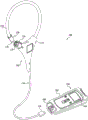
fig. 1 is an example of a current measurement system with an open loop in accordance with one or more embodiments of the present disclosure;
FIG. 2 is an example of the current measurement system of FIG. 1 having a loop that is closed around a wire and measuring current flowing through the wire in accordance with one or more embodiments of the present disclosure;
FIG. 3 is a block diagram of a current sensor having a loop including a magnetic field sensor positioned between a magnetically permeable section and a coil in accordance with one or more embodiments of the present disclosure;
FIG. 4 is a block diagram of a current sensor having a loop including at least two magnetic field sensors and two separate magnetically permeable sections, according to one or more embodiments of the present disclosure;
fig. 5 shows two cross-sectional views of a bundle of magnetically conductive wire bundles at different longitudinal positions along the bundle in accordance with one or more embodiments of the present disclosure;
FIG. 6 is a bundle of magnetically conductive wire strands wrapped relative to one another in accordance with one or more embodiments of the present disclosure; and
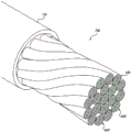
fig. 7 is a bundle of magnetically conductive wire harnesses including a plurality of bundles of wound wire harnesses in accordance with one or more embodiments of the present disclosure.
Detailed Description
The following detailed description of various embodiments of the disclosed subject matter is set forth in connection with the accompanying drawings (where like numerals represent like elements), and is not intended to represent the embodiments only. The various embodiments described in this disclosure are merely examples or illustrations of what should be considered preferred or advantageous over other embodiments. The illustrated examples are not intended to be exhaustive or to limit the claimed subject matter to the precise forms disclosed.
The following discussion provides examples of systems, devices, and methods relating to flexible current sensors capable of measuring current flowing through a wire without contacting the wire. In various embodiments, the flexible current sensor may have a size, shape, and profile similar to the flexible loop of the rogowski coil. However, unlike rogowski coils, the current sensors described herein may sense Direct Current (DC). In some embodiments, the current sensor may also sense Alternating Current (AC). The current sensor senses the flow of current in a similar manner to a clamp or jaw type current sensor, but using a different magnetic core.
Fig. 1 shows a current measurement system 100 with a current sensor 102 and a measurement device 190. The current sensor 102 includes a loop 110 having a flexible portion. The loop 110 includes a magnetically conductive material or "core". The magnetically permeable material includes a plurality of magnetically permeable strands. The wiring harness, and thus the loop 110, may be flexible or bendable. The wiring harness may include an outer layer of insulating material that helps insulate the wiring harness from one another. Current sensor 102 uses loop 110 to sense current flow in the wire rather than using a heavy rigid jaw that is opened and closed with a motor. In some embodiments, the loop may be opened and closed such that it may be positioned around a wire having a current flow without interrupting the current flow.
As described in greater detail herein, the plurality of flexible magnetically permeable strands in the loop 110 may be woven, braided, wound, or arranged in a pattern. Loop 110 also includes at least one magnetic field sensor and a signal cable 116 that may include a flexible portion. Signal cable 116 may be coupled to one or more components of loop 110, such as one or more magnetic field sensors.
The magnetic field sensors may be placed in the gaps between the magnetically permeable materials. Various types of magnetic field sensors may be used. For example, the magnetic field sensor may comprise a hall effect sensor. Loop 110 may include an overhang 114 that includes a magnetic field sensor. Overhang 114 may protect the magnetic field sensor.
The current sensor 102 is coupled or couplable to the measurement device 190. The signal cable 116 may extend from the loop 110 and may include a coupling 150 in a housing 192 of the input measurement device 190. The measurement device 190 includes a measurement circuit capable of receiving the output provided by the current sensor 102, calculating a current value, and presenting the calculated current value to a user. The measurement circuitry of the measurement device 190 may also be used for other functions, such as receiving input from other sensors and calculating measurements. The measurement device 190 may be implemented as various electronic measurement devices, such as, for example, a multimeter. The measurement value representing the current sensed by the current sensor 102 may be displayed on the display 198 of the measurement device 190.
In addition to being coupled or couplable to current sensor 102, measurement device 190 may be coupled or couplable to a rogowski coil or other sensor. For example, the coupling 150 may be substantially identical to that of a rogowski coil, and the current sensor 102 or rogowski coil may be input into a port 196 in the housing 192 of the measurement device 190. In some embodiments, the measurement device 190 may have multiple input ports. In some embodiments, the measurement device 190 may be coupled or coupled to both the rogowski coil and the current sensor 102. The measurement device 190 may be configured to selectively display measurement inputs from the current sensor 102 or the rogowski coil in response to user inputs to the measurement device 190. This embodiment may allow a technician to carry the measurement device 190 and use it with the current sensor 102 and other sensors, rather than carrying separate measurement devices for each sensor. For example, a technician may use measuring device 190 to measure AC current in conjunction with the rogowski coil, and measuring device 190 to measure AC current in conjunction with current sensor 102, respectively. This may reduce the size and weight of the equipment that the technician must carry to the worksite, and may also reduce the number of round trips to replace the measurement device at the worksite.
Still referring to fig. 1, the loop 110 of the current sensor 102 may include a first end 128 having the fastening element 18. The loop 110 may have a fastener receiver 120 attached at or near the second end 129 of the loop 110. The fastening element 118 and the fastener receiver 120 are configured to mate with one another. For example, the fastening element 118 and the fastener receiver 120 may comprise a quarter-turn type fastener and a compatible fastener receiver, respectively. At least one magnetic field sensor may be positioned at one of the first end 128 and the second end 129, and a magnetically permeable material may be positioned at the other of the first end 128 and the second end 129.
The magnetically permeable material may provide a magnetic field to a sensing element of the at least one magnetic field sensor. In some embodiments, an end of the plurality of strands of magnetically permeable material (e.g., a strand) in the loop 110 is positioned at one of the first end 128 and the second end 129, and a magnetic field is provided to the magnetic field sensor by the end of the plurality of strands of magnetically permeable material. A gap may exist between the magnetic field sensor and the magnetically permeable material, and a magnetic field from the magnetically permeable material may pass through the gap.
Consistent and precise positioning of loop 110 and magnetic field sensors may help to achieve accurate and reliable measurements. In some embodiments, the gap between the magnetically permeable material and the magnetic field sensor is minimized. Minimizing the gap reduces field losses and interference from external fields. In some embodiments, the mating of the fastening element 118 and the fastener receptacle 120 automatically positions or aligns the magnetically permeable material with the magnetic field sensor such that the magnetic field is focused via the magnetic field sensor. The mating between the fastening element 118 and the fastener receiver 120 may position the first end 128 and the second end 129 relative to each other, align the magnetic fields provided by the wiring harness and the magnetic field sensor, and/or minimize the gap between the magnetically permeable material and the magnetic field sensor.
Fig. 2 shows the current sensor 102 in operation. The current sensor 102 is connected to the measurement device 190 via a signal cable 116. The loop 110 is closed and positioned around the conductor C, which has a DC current flowing therethrough. The fastening element 118 and the fastener receiver 128 mate, and the magnetically permeable material (e.g., a wire harness) and the magnetic sensor are aligned by the mating. The measured current value of 0.2mA is displayed on display 198.
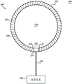
Fig. 3 shows a block diagram of a current sensor 300 having a loop 310 that includes a magnetic field sensor 314 and a magnetically permeable section 304, which may also be referred to as a "core". The current sensor 300 may be suitable for use in conjunction with the system 100 shown in fig. 1. As shown in fig. 3, the current sensor 300 is closed. The magnetically permeable section 304 may have a first end 318 and a second end 319. The magnetically permeable section 304 comprises a plurality of strands of magnetically permeable material. In some embodiments, the strand of magnetically permeable material extends in the loop 310 from the first end 318 to the second end 319. Loop 310 is coupled to measurement device 190 via signal cable 316. When the loop 310 is in the closed position, the gap 302 may be defined within the magnetically permeable section 304.
A magnetic field sensor 314 is disposed in the gap 302 and may be attached to one of the first end 318 and the second end 319. The other of the first end 318 and the second end 319 is positioned proximate the magnetic field sensor 314. The magnetic field sensor 314 is configured to receive a magnetic field from the other of the first end 318 and the second end 319. The magnetic field may be concentrated or focused by the magnetically permeable section 304. The current sensor 300 may be configured as an "open loop" sensor. The current sensor 314 may provide an output signal indicative of the current flowing through a circuit member, such as a cable or other conductor (e.g., as shown in fig. 2) surrounded by the loop 310. For example, the magnetic field sensor 314 may be a hall effect sensor, and the hall voltage of the sensor may be provided as an output signal to a measurement device.
In some embodiments, the current sensor 300 includes a toroidal coil 360 external to and surrounding the magnetically permeable section 304. Coil 360 is electrically conductive and may be coupled to signal cable 316. Coil 360 may be driven by an amplifier circuit such that current flows through coil 360. The current flowing through the coil 360 may be provided by a source included with or attached to the measurement device 190, for example. In some embodiments, current sensor 300 is "closed loop". Current sensor 300 uses an amplifier circuit to generate a current through the coil to substantially cancel the magnetic field of the current from the wire of loop 310 by generating a magnetic flux of substantially the same magnitude in the opposite direction to the magnetic field of the current from the wire. The current through the coil 360 may cause the magnetic core and the sensor to be at the same operating point and may reduce the undesirable effects of non-linearity from the sensor or core. The current through the coil 360 may be proportional to the current through the wire being measured. The current generated by the amplifier circuit may be indicative of the current flowing through the wire.
Fig. 4 shows a block diagram of a current sensor 400 having a loop 410, a first magnetic field sensor 414, and a second magnetic field sensor 415. The current sensor 400 may be suitable for use in conjunction with the current measurement system 100 shown in fig. 1. The current sensor 400 is similar to the current sensor 300 except that it has two magnetic field sensors instead of a single magnetic field sensor. Loop 410 includes a first magnetically permeable section 404 and a second magnetically permeable section 405. At least one of the first and second magnetically permeable sections 404, 405 comprises a plurality of strands of magnetically permeable material. The loop 410 includes a first gap 402 and a second gap 403. The first and second magnetically permeable sections 404, 405 are thus separated from each other. The first end 418 of the first magnetically permeable section 404 and the first end 438 of the second section 405 define the first gap 402.
A first magnetic field sensor 414 is disposed in the first gap 402 and is configured to sense the magnetic field provided by the magnetically permeable material of the first and second magnetically permeable sections 404, 405. The second end 419 of the first magnetically permeable section 404 and the second end 439 of the second magnetically permeable section 405 define a second gap 403. A second magnetic field sensor 415 is arranged in the second gap 403. To reduce field losses and interference from external fields, the space between the magnetic field sensors 414 and 415 and the ends 418, 419, 438, and 439 of the loop 410, respectively, may be minimized. For example, ends 419 and 439 should be positioned proximate to or attached to second magnetic field sensor 415 during operation. The external field can be compensated using two magnetic field sensors positioned relative to each other across the inner space of the loop. The coil 360 may help reduce measurement errors by eliminating or reducing the effects of magnetic influences from the external volume 380. The current sensor 400 may be open-loop or closed-loop. For example, although not shown, a current driven through toroidal coil 360 as shown in fig. 3 may also be used in conjunction with current sensor 400 to reduce non-linearity in loop 410.
Other embodiments are possible. For example, in addition to first and second magnetically permeable sections 404, 405, loop 410 may include one or more additional separate sections of magnetically permeable material. Additional magnetic field sensors may be disposed in the gaps between the sections of magnetically permeable material. In some embodiments, the current sensor 102 or 400 includes a coil similar to the coil 360 shown in fig. 3. In addition, the current sensors 102, 300, and 400 may use different magnetic field sensors. For example, the magnetic field sensor may include one or more of a hall effect sensor, a flux gate, an Anisotropic Magnetoresistor (AMR) sensor, or a Giant Magnetoresistive (GMR) sensor. The magnetic field sensor may include other devices capable of measuring the strength of the magnetic field in the gap.
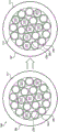
Fig. 5 shows a cross-sectional view of a bundle 500 of magnetically permeable wire bundles in a first position 501 and a second position 502 located at a longitudinal distance from the first position 501. The bundle 500 may be suitable for use in conjunction with the system 100 shown in fig. 1. The bundle 500 includes harnesses 521, 522, 523, 531, 532, and 533. The wire harnesses are arranged such that their relative positions with respect to each other vary over the length of the bundle. The wire harness includes an inner portion 504 that includes a magnetically permeable material. The wiring harness may include an outer portion 506 having an insulating material for isolating the wiring harness from one another. Wiring harnesses with and without exterior portions of insulation are suitable for use in various embodiments of the present disclosure, such as current sensors 102, 300, and 400. The use of multiple wire harnesses minimizes eddy current effects that can cause current to form in the sensor, which causes heating of the sensor and limits its ability to measure magnetic fields. The use of multiple wire harnesses may also allow the magnetically permeable section to be more flexible or bendable than the current clamping device.
For example, the bundle 500 may have a circular or round cross-sectional shape. In some embodiments, the shape of the bundle conforms to the shape of the sensing element of the magnetic field sensor. Upon alignment, a large magnetic field from the bundle is provided to the magnetic field sensor. In one embodiment, bundle 500 includes approximately twenty wire harnesses, although a different number of wire harnesses may be used. The strands may be arranged such that they provide a magnetic field across a gap, such as the first gap 402 shown in fig. 4. The bundle 500 may include an outer layer 512, which may include an insulating material for protecting the wiring harness from interference or damage.
As shown in fig. 5, bundle 500 has an outer portion of the wiring harness outside of wire 520 and an inner portion of the wiring harness inside of wire 520. At the first position 501, the wire harnesses 521, 522, and 523 are in the inner portion, and the wire harnesses 531, 532, and 533 are in the outer portion of the wire harness 500. As shown, the position of the wire harnesses varies with respect to each other along the length of the bundle 500. For example, at the second position 502, the harnesses 521, 522, and 523 are inside and the harnesses 531, 532, and 533 are outside. In some embodiments, the wiring harness is interleaved between the outer and inner sections of the bundle 500 such that the wiring harness passes through the inner and outer portions of the bundle over the length of the wiring harness 500. In some embodiments, the wire harnesses are staggered multiple times over the length of the bundle 500 between the outer and inner sections of the bundle 500.
In some embodiments, the wire harness is staggered from within the inner portion and from within the outer portion of the bundle such that the wire harness has about the same length dimension in the inner portion as in the outer portion over the length of the wire harness for the bundle. In some embodiments, the wire harness may be positioned in the inner portion and the outer portion by the same amount, on average, within the length of the bundle. Various patterns may be used to arrange the wiring harness. In some embodiments, the proportion of each wire bundle in the outer portion of the bundle is about the same over the entire length. In some embodiments, the proportion of each wire bundle in the inner portion of the bundle is about the same over the entire length. These patterns may provide electrical and mechanical advantages, such as allowing loops in current sensors as described herein to be robust and flexible. Arranging the strands and/or various patterns of strand sizes may allow the bundle to be resilient. Some patterns may allow the loops to be flexible and resilient. This property provides significant advantages over current sensors of the prior art clip type.
As described above with respect to fig. 3, accurate and consistent positioning of the magnetically permeable material relative to the one or more magnetic field sensors can be important to provide accurate and consistent measurements. The distance between the end of the wire harness and the magnetic field sensor may be minimized and the wire harness may be aligned with the magnetic field sensor. Some magnetically permeable materials may not be as flexible as typical wire materials, and some wire harnesses may harden and/or break over time and use, resulting in size variations of a few thousandths of an inch. Such changes in the positioning of the wire harness relative to the magnetic field sensor may cause inconsistent measurements. In some embodiments, the precise distance between the wire harness and the magnetic field sensor is achieved by polishing the end. In some embodiments, the ends of the wire harness may be sealed with an epoxy to help maintain the position of the wire harness consistently after the wire harness is bent.
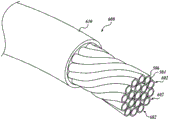
Fig. 6 shows a bundle 600 of wound wire bundles 602. The wound wire harness may provide improved properties with respect to flexibility and resilience compared to a straight wire harness. As shown in fig. 6, the wire harness is wound such that its position changes in the longitudinal direction of the bundle. The bundle 600 may have an outer layer 610 that may include an insulating material.
Fig. 7 shows a bundle 700 of bundles 600 of wire harnesses 602. As shown, the bundle 600 may be wound in the longitudinal direction of the bundle 700. In some embodiments, the bundle 600 may be woven together. The bundles 600 may be arranged in a similar pattern as described herein. The bundle 700 may have an outer layer 710, which may include an insulating material. The outer layer 710 may help protect against short circuits or external interference.
Various combinations of patterns of wire harnesses and bundles may be used in conjunction with embodiments of the current sensors disclosed herein. Various winding techniques may arrange the strands and/or bundles of strands. In some embodiments, Litz winding technology may be used such that the wire harnesses are arranged in a Litz pattern. For example, the wiring harness may comprise magnetically permeable material and be arranged similar to the RoundType 2 cable of New England Wire Technologies.
The overall size of bundles 500, 600, and 700 may vary. The bundle may be sized and configured such that one end of the bundle overlaps the sensing element of the magnetic field sensor. For example, the number of strands included in the bundle and the shape of the bundle may be determined based on the size of the sensing element and the cross-sectional area of the strands, including the inner and outer portions of the bundle. For example, to overlap the ends of the bundle with the sensing elements of the magnetic field sensor, the surface area and size of the sensing elements may be such that the cross-sectional area at the ends of the bundle is larger than the area of the sensing elements of the magnetic field sensor, so that the magnetic field from the wire bundle in the bundle is sensed by the magnetic field sensor.
The magnetically permeable material in embodiments of the present disclosure may have at least 5.0x10⁻³Magnetic permeability of H/m. A material with such a permeability material will increase the magnetic field in the vicinity of the material, which may help to focus the magnetic field across the gap comprising the magnetic field sensor. Different magnetically permeable materials and insulating materials may be used for the inner portion 504 and the outer portion 506 of the wire harness, respectively. Increasing the magnetic permeability of the wire harness may increase the sensitivity of a current sensor (e.g., current sensor 102, 300, or 400). For example, the magnetically permeable material in the inner portion 504 of the wire harness may comprise a nickel-iron alloy, such as electrical steel.
In some embodiments, the magnetically permeable material of the wire harness comprises mu metal. The mu metal may have at least 2.5x10⁻²Magnetic permeability of H/m. Examples of commercially available μmetals include mum, mum 1 and mum 2. The mu metal may be formed as a thin wire. It is also desirable that the wire harness comprises a ductile and machinable material. A magnetically permeable material having good strand resiliency so that the strand 500 does not permanently buckle or bend when placed around an electrical component or wire to be tested can provide significant advantages. Mu-metal strands have favorable resilient properties and have greater ductility and machinability than other nickel-iron alloys. Materials with low loss factors, such as electrical steel, may be used. The use of materials with low dissipation factors may provide improved accuracy and repeatable properties.
In operation, a magnetic field may be transmitted from an end of the plurality of insulated magnetically permeable strands of the magnetically permeable loop to a magnetic field sensor positioned proximate to the end of the plurality of insulated magnetically permeable strands. Signals may be output by the magnetic field sensor based on the magnetic field transmitted from the ends of the plurality of wire harnesses, the signals being representative of the current flowing through the electrical component or wire being tested.
In some embodiments, a magnetically conductive loop is positioned around the wire prior to passing the magnetic field to the magnetic field sensor. By closing the magnetically conductive loop with the fastening device, the ends of the plurality of insulated magnetically conductive strands may be aligned with the sensing element of the magnetic sensor.
It will be appreciated that various magnetically permeable wire bundles, and arrangement patterns (e.g., wire bundles 500, 600, and 700) may be suitable for the magnetically permeable portion of the loop 110 in fig. 1 and 2, the magnetically permeable section 304 of fig. 3, and the first and second magnetically permeable sections 404, 405 of fig. 4.
Many variations of the pattern are possible. Braiding, weaving, winding, and other patterns or arrangements of strands may provide mechanical and electrical advantages, and may also provide desirable magnetic properties when incorporated into a current measurement system (e.g., current measurement system 100 in fig. 1). The braiding or weaving may allow the lengths of the individual strands and bundles to remain fixed when the loop 110 is bent, which allows the strands to be uniform at the ends when the loop 110 is bent. The lack of uniformity at the ends can reduce measurement accuracy. If the first ends 318 of the plurality of strands do not conform when bent, some strands or bundles may be pulled away from the magnetic field sensor 314 when bent. Various wiring harness arrangements may be used, such as the arrangements shown in fig. 5, 6 and 7. As previously described, in some embodiments, the bundle is formed by winding the wire harness using the Litz winding method.
The number of strands in the bundle, the strand size, the magnetically permeable material of the strands, and other strand properties may vary. In some embodiments, a plurality of strands 500 may be woven together. Woven or braided strands may provide advantages. For example, the wire harnesses in bundle 500 may be more flexible, durable, and able to withstand vibration than straight lines. Multiple bundles 500 of wire bundles may be woven together.
In the previous description, numerous details were set forth to provide a thorough understanding of one or more embodiments of the present disclosure. It will be apparent, however, to one skilled in the art, that many embodiments of the present disclosure may be practiced without some or all of these specific details. It will be appreciated that variations may be made in various embodiments without departing from the spirit and scope of the disclosure. Thus, it will be appreciated that embodiments of the present disclosure may use any combination of the features described herein.
Claims (21)
1. An apparatus for measuring current flowing through a wire, the apparatus comprising:
a magnetically conductive loop positionable around a wire whose current is to be measured, wherein the magnetically conductive loop comprises a bundle of strands comprising a plurality of strands; and
a magnetic field sensor positioned adjacent to an end of the plurality of wire harnesses to sense a magnetic field,
wherein each of the plurality of strands comprises magnetically permeable material and the strands of the plurality of strands are arranged such that they pass through an inner portion of the bundle and an outer portion of the bundle at least once over the length of the magnetically permeable loop,
wherein the plurality of wire harnesses is configured to convey a magnetic field to the magnetic field sensor, the magnetic field indicative of current flowing through the wire, an
Wherein the magnetic field sensor is configured to output a signal indicative of current flowing through the wire based on a magnitude of a magnetic field sensed by the magnetic field sensor.
2. The apparatus of claim 1, further comprising:
a coil wrapped around the magnetically conductive loop; and
a drive circuit coupled to the coil and the magnetic field sensor,
wherein the drive circuit is configured to generate a current that flows through the coil and substantially cancels the magnetic field, an
Wherein the current generated by the driver circuit is indicative of the current flowing through the wire.
3. The apparatus of claim 1, wherein one or more of the plurality of strands has an outer layer of insulating material surrounding the magnetically permeable material.
4. The device of claim 1, wherein the wire harnesses in the plurality of wire harnesses are arranged such that the wire harnesses are interleaved between inner and outer portions of the wire harness bundle, wherein the wire harnesses have about the same amount of length of the magnetically conductive loop in the inner portion of the wire harness bundle as the wire harnesses in the outer portion of the wire harness bundle.
5. The device of claim 1, wherein the harnesses in the plurality of harnesses are arranged such that the harnesses are positioned within the length of the harness bundle to have the same amount of length on average in an inner portion of the harness bundle and in an outer portion of the harness bundle.
6. The device of claim 1, wherein a bundle of the plurality of bundles is wound.
7. The device of claim 1, further comprising a fastening device configured to open and close the magnetically conductive loop.
8. The device of claim 7, wherein the fastening device is configured to position ends of the plurality of wire harnesses to overlap a sensing element of the magnetic field sensor.
9. The device of claim 7, wherein the plurality of wire harnesses is a first plurality of wire harnesses, the device further comprising a second plurality of wire harnesses, wherein the fastening device is configured to position ends of the first and second plurality of wire harnesses in overlapping relation with a sensing element of the magnetic field sensor.
10. The apparatus of claim 1, wherein the magnetic field sensor is a first magnetic field sensor, the magnetically conductive loop further comprising a second magnetic field sensor positioned adjacent an end of the plurality of wire harnesses to sense a magnetic field, and wherein the first and second magnetic field sensors are positioned across the magnetically conductive loop relative to each other.
11. The apparatus of claim 1, wherein ones of the plurality of strandsThe inner layer of the wiring harness comprises at least 5x10⁻³A nickel-iron alloy of H/m permeability.
12. The device of claim 11, wherein a bundle of the plurality of bundles comprises mu metal.
13. The apparatus of claim 1, wherein the magnetic field sensor comprises at least one of a hall effect sensor, a flux gate, a heterogeneous magnetoresistor sensor, or a large magnetoresistive sensor.
14. The device of claim 1, wherein the plurality of wire harnesses is flexible.
15. The device of claim 1, wherein the plurality of wire harnesses is configured to convey a magnetic field to the magnetic field sensor, the magnetic field indicative of a direct current flowing through the wire.
16. The apparatus of claim 1, further comprising a toroidal coil configured to encircle the magnetically conductive loop to reduce non-linearity in at least one of the magnetic field sensor and the magnetically conductive loop.
17. A method of measuring current flowing through a wire, comprising:
positioning a magnetically conductive loop around the wire, wherein the magnetically conductive loop comprises a bundle of strands comprising a plurality of magnetically conductive strands having one end positioned adjacent to a magnetic field sensor, wherein the magnetically conductive strands of the plurality of magnetically conductive strands are arranged such that they pass through an inner portion of the bundle of strands and an outer portion of the bundle of strands at least once over a length of the magnetically conductive loop; and
communicating a magnetic field from an end of the plurality of magnetically permeable wire strands to the magnetic field sensor, wherein the magnetic field sensed by the magnetic field sensor is indicative of a current flowing through the wire.
18. The method of claim 17, further comprising: outputting a signal from the magnetic field sensor indicative of current flowing through the wire based on a magnitude of a magnetic field transmitted from ends of the plurality of magnetically permeable wire strands to the magnetic field sensor.
19. The method of claim 17, further comprising: generating a current of a coil surrounding the magnetically conductive loop to substantially cancel the magnetic field, wherein the current generated to substantially cancel the magnetic field is indicative of a current flowing through the wire.
20. The method of claim 17, further comprising:
aligning ends of the plurality of magnetically conductive strands with a sensing element of the magnetic field sensor by closing the magnetically conductive loop with a fastening device prior to conveying the magnetic field to the magnetic field sensor.
21. A system for measuring current flowing through a wire, the system comprising the device of claim 1 and a measuring device coupleable to the device of claim 1 and a rogowski coil, wherein the measuring device is configured to output a current measurement representative of current flowing through the wire based on a signal received from one of the device of claim 1 and a rogowski coil.
Applications Claiming Priority (2)
| Application Number | Priority Date | Filing Date | Title |
|---|---|---|---|
| US14/524,886 US9541581B2 (en) | 2014-10-27 | 2014-10-27 | Flexible current sensor |
| US14/524886 | 2014-10-27 |
Publications (2)
| Publication Number | Publication Date |
|---|---|
| CN105548650A CN105548650A (en) | 2016-05-04 |
| CN105548650B true CN105548650B (en) | 2020-11-06 |
Family
ID=54364118
Family Applications (1)
| Application Number | Title | Priority Date | Filing Date |
|---|---|---|---|
| CN201510705162.XA Active CN105548650B (en) | 2014-10-27 | 2015-10-27 | Flexible current sensor |
Country Status (5)
| Country | Link |
|---|---|
| US (1) | US9541581B2 (en) |
| EP (1) | EP3015871A1 (en) |
| JP (1) | JP6712455B2 (en) |
| CN (1) | CN105548650B (en) |
| TW (1) | TWI691726B (en) |
Families Citing this family (12)
| Publication number | Priority date | Publication date | Assignee | Title |
|---|---|---|---|---|
| TWD181396S (en) | 2015-11-11 | 2017-02-21 | 富克有限公司 | Ac clamp accessory |
| USD820128S1 (en) * | 2016-10-26 | 2018-06-12 | Klein Tools, Inc. | Voltage tester |
| US10732208B2 (en) | 2017-02-13 | 2020-08-04 | Ladislav Gr{hacek over (n)}o | Flexible current sensor with stranded core |
| FR3076657B1 (en) * | 2018-01-05 | 2021-04-09 | Socomec Sa | OPENING CURRENT TRANSFORMER WITH SOFT MAGNETIC CORE |
| JP7058548B2 (en) * | 2018-05-09 | 2022-04-22 | 日置電機株式会社 | Current sensor and measuring device |
| US10551416B2 (en) * | 2018-05-09 | 2020-02-04 | Fluke Corporation | Multi-sensor configuration for non-contact voltage measurement devices |
| US10746767B2 (en) * | 2018-05-09 | 2020-08-18 | Fluke Corporation | Adjustable length Rogowski coil measurement device with non-contact voltage measurement |
| US10908188B2 (en) * | 2018-05-11 | 2021-02-02 | Fluke Corporation | Flexible jaw probe for non-contact electrical parameter measurement |
| CN110244103A (en) * | 2019-01-16 | 2019-09-17 | 国网浙江杭州市富阳区供电有限公司 | A kind of clamp on amperemeter based on Rogowski coil |
| USD911858S1 (en) * | 2019-04-25 | 2021-03-02 | Klein Tools, Inc. | Test device |
| USD946430S1 (en) * | 2020-07-28 | 2022-03-22 | Chauvin Arnoux | Power energy logger |
| DE102020124516A1 (en) | 2020-09-21 | 2022-03-24 | Turck Duotec GmbH | Sensor with fiber optic connection |
Citations (6)
| Publication number | Priority date | Publication date | Assignee | Title |
|---|---|---|---|---|
| CN1570654A (en) * | 2004-04-28 | 2005-01-26 | 邹高芝 | Magnetic core sheath free coil magnetic core pack for current sensor |
| CN101957394A (en) * | 2009-07-17 | 2011-01-26 | 福禄克公司 | The jaw type multimeter that is used for measuring the conductor alternating current of band Roc Paderewski coil |
| CN202661526U (en) * | 2012-01-19 | 2013-01-09 | 邹高芝 | Coaxial double-loop magnetic core coil assembly for core-through type high precision closed-loop type Hall current sensor |
| CN103119452A (en) * | 2010-09-21 | 2013-05-22 | 莱姆知识产权股份有限公司 | Closed-loop current transducer with switched mode amplifier |
| CN103575329A (en) * | 2012-08-03 | 2014-02-12 | 弗卢克公司 | Handheld devices, systems, and methods for measuring parameters |
| CN103675403A (en) * | 2012-08-28 | 2014-03-26 | 国际商业机器公司 | Flexible current and voltage sensor |
Family Cites Families (16)
| Publication number | Priority date | Publication date | Assignee | Title |
|---|---|---|---|---|
| US3983521A (en) * | 1972-09-11 | 1976-09-28 | The Furukawa Electric Co., Ltd. | Flexible superconducting composite compound wires |
| CH648148A5 (en) * | 1979-02-09 | 1985-02-28 | Bbc Brown Boveri & Cie | SUPERCONDUCTIVE CABLE. |
| US4558276A (en) | 1983-05-13 | 1985-12-10 | Leon J. Comeau | Device and method for sensing electric current in a conductor |
| JPS60126393A (en) * | 1983-12-03 | 1985-07-05 | 朝日ミニロープ販売株式会社 | Rope |
| JPH053987Y2 (en) * | 1986-02-25 | 1993-01-29 | ||
| JPH01112175A (en) * | 1987-10-26 | 1989-04-28 | Chubu Denki Hoan Kyokai | Leak current detector |
| JPH06174753A (en) | 1992-12-02 | 1994-06-24 | Sansha Electric Mfg Co Ltd | High current detector |
| JP4332623B2 (en) * | 2003-02-26 | 2009-09-16 | テクトロニクス・インコーポレイテッド | Current probe |
| US7205947B2 (en) * | 2004-08-19 | 2007-04-17 | Harris Corporation | Litzendraht loop antenna and associated methods |
| CA2600862A1 (en) * | 2005-02-18 | 2007-09-07 | Airpax Corporation | Apparatus comprising circuit breaker with adjunct sensor unit |
| JP2008145352A (en) * | 2006-12-12 | 2008-06-26 | Jeco Co Ltd | Current sensor and current detecting method |
| US8203328B2 (en) * | 2009-03-12 | 2012-06-19 | Consolidated Edison Company Of New York, Inc. | Current measuring device |
| US8461824B2 (en) * | 2010-06-07 | 2013-06-11 | Infineon Technologies Ag | Current sensor |
| CN102323467A (en) * | 2011-08-31 | 2012-01-18 | 清华大学 | Giant magnetoresistive effect current sensor using amorphous alloy magnetic ring structure |
| US8952686B2 (en) * | 2011-10-25 | 2015-02-10 | Honeywell International Inc. | High current range magnetoresistive-based current sensor |
| US9198500B2 (en) * | 2012-12-21 | 2015-12-01 | Murray W. Davis | Portable self powered line mountable electric power line and environment parameter monitoring transmitting and receiving system |
-
2014
- 2014-10-27 US US14/524,886 patent/US9541581B2/en active Active
-
2015
- 2015-10-19 TW TW104134207A patent/TWI691726B/en active
- 2015-10-21 JP JP2015207012A patent/JP6712455B2/en active Active
- 2015-10-27 EP EP15191726.7A patent/EP3015871A1/en not_active Withdrawn
- 2015-10-27 CN CN201510705162.XA patent/CN105548650B/en active Active
Patent Citations (6)
| Publication number | Priority date | Publication date | Assignee | Title |
|---|---|---|---|---|
| CN1570654A (en) * | 2004-04-28 | 2005-01-26 | 邹高芝 | Magnetic core sheath free coil magnetic core pack for current sensor |
| CN101957394A (en) * | 2009-07-17 | 2011-01-26 | 福禄克公司 | The jaw type multimeter that is used for measuring the conductor alternating current of band Roc Paderewski coil |
| CN103119452A (en) * | 2010-09-21 | 2013-05-22 | 莱姆知识产权股份有限公司 | Closed-loop current transducer with switched mode amplifier |
| CN202661526U (en) * | 2012-01-19 | 2013-01-09 | 邹高芝 | Coaxial double-loop magnetic core coil assembly for core-through type high precision closed-loop type Hall current sensor |
| CN103575329A (en) * | 2012-08-03 | 2014-02-12 | 弗卢克公司 | Handheld devices, systems, and methods for measuring parameters |
| CN103675403A (en) * | 2012-08-28 | 2014-03-26 | 国际商业机器公司 | Flexible current and voltage sensor |
Also Published As
| Publication number | Publication date |
|---|---|
| EP3015871A1 (en) | 2016-05-04 |
| JP6712455B2 (en) | 2020-06-24 |
| CN105548650A (en) | 2016-05-04 |
| TW201625965A (en) | 2016-07-16 |
| JP2016085216A (en) | 2016-05-19 |
| US9541581B2 (en) | 2017-01-10 |
| TWI691726B (en) | 2020-04-21 |
| US20160116506A1 (en) | 2016-04-28 |
Similar Documents
| Publication | Publication Date | Title |
|---|---|---|
| CN105548650B (en) | Flexible current sensor | |
| TWI820127B (en) | Electrical parameter sensor probe and device for measuring an electrical parameter in an insulated conductor | |
| CN102985838B (en) | For the method and apparatus detecting the magnetic characteristic parameter in magnetic core | |
| US7755347B1 (en) | Current and voltage measurement device | |
| CN101241147B (en) | Apparatus for measuring an electric current flowing through an electrical conductor | |
| US20070188170A1 (en) | Fluxgate and fluxgate magnetometers | |
| JP2016085216A5 (en) | ||
| JP5558559B2 (en) | Sensor and method for measuring molten metal level | |
| US8922193B2 (en) | Current meter | |
| CN107103982B (en) | Magnetic core for sensor | |
| KR102182504B1 (en) | Apparatus and method for measuring the current strength of individual conductors in a multi-core system | |
| EP2948779B1 (en) | Flexible magnetic field sensor | |
| US20230251289A1 (en) | Non-contact voltage measurement with adjustable size rogowski coil | |
| US20160327594A1 (en) | Current sensor with stray magnetic field rejection | |
| JP2012098205A (en) | Current measurement method and magnetic sensor device | |
| US10018656B2 (en) | Device, arrangement, and method for measuring a current intensity in a primary conductor through which current flows | |
| KR102330162B1 (en) | current sensor | |
| CA2534928A1 (en) | Current sensor | |
| JP7192863B2 (en) | Power supply device, power line physical quantity measurement device and communication device | |
| CN103688146B (en) | For calibrate and measure rail at least some of in the system of mechanical stress | |
| JP2020038113A (en) | Current measuring device and current measuring method | |
| JP2011202989A (en) | Current measurement device and current measurement method | |
| CN114325048A (en) | Self-energy-taking flexible current measuring device |
Legal Events
| Date | Code | Title | Description |
|---|---|---|---|
| C06 | Publication | ||
| PB01 | Publication | ||
| SE01 | Entry into force of request for substantive examination | ||
| SE01 | Entry into force of request for substantive examination | ||
| GR01 | Patent grant | ||
| GR01 | Patent grant |