CN103575329A - Handheld devices, systems, and methods for measuring parameters - Google Patents
Handheld devices, systems, and methods for measuring parameters Download PDFInfo
- Publication number
- CN103575329A CN103575329A CN201310334993.1A CN201310334993A CN103575329A CN 103575329 A CN103575329 A CN 103575329A CN 201310334993 A CN201310334993 A CN 201310334993A CN 103575329 A CN103575329 A CN 103575329A
- Authority
- CN
- China
- Prior art keywords
- equipment
- main process
- parameter
- measured value
- measuring
- Prior art date
- Legal status (The legal status is an assumption and is not a legal conclusion. Google has not performed a legal analysis and makes no representation as to the accuracy of the status listed.)
- Pending
Links
Images


Classifications
-
- G—PHYSICS
- G01—MEASURING; TESTING
- G01R—MEASURING ELECTRIC VARIABLES; MEASURING MAGNETIC VARIABLES
- G01R1/00—Details of instruments or arrangements of the types included in groups G01R5/00 - G01R13/00 and G01R31/00
- G01R1/02—General constructional details
- G01R1/06—Measuring leads; Measuring probes
- G01R1/067—Measuring probes
- G01R1/06788—Hand-held or hand-manipulated probes, e.g. for oscilloscopes or for portable test instruments
-
- G—PHYSICS
- G01—MEASURING; TESTING
- G01R—MEASURING ELECTRIC VARIABLES; MEASURING MAGNETIC VARIABLES
- G01R1/00—Details of instruments or arrangements of the types included in groups G01R5/00 - G01R13/00 and G01R31/00
- G01R1/02—General constructional details
- G01R1/04—Housings; Supporting members; Arrangements of terminals
-
- G—PHYSICS
- G01—MEASURING; TESTING
- G01R—MEASURING ELECTRIC VARIABLES; MEASURING MAGNETIC VARIABLES
- G01R15/00—Details of measuring arrangements of the types provided for in groups G01R17/00 - G01R29/00, G01R33/00 - G01R33/26 or G01R35/00
- G01R15/12—Circuits for multi-testers, i.e. multimeters, e.g. for measuring voltage, current, or impedance at will
- G01R15/125—Circuits for multi-testers, i.e. multimeters, e.g. for measuring voltage, current, or impedance at will for digital multimeters
-
- H—ELECTRICITY
- H04—ELECTRIC COMMUNICATION TECHNIQUE
- H04Q—SELECTING
- H04Q9/00—Arrangements in telecontrol or telemetry systems for selectively calling a substation from a main station, in which substation desired apparatus is selected for applying a control signal thereto or for obtaining measured values therefrom
-
- G—PHYSICS
- G01—MEASURING; TESTING
- G01R—MEASURING ELECTRIC VARIABLES; MEASURING MAGNETIC VARIABLES
- G01R1/00—Details of instruments or arrangements of the types included in groups G01R5/00 - G01R13/00 and G01R31/00
- G01R1/02—General constructional details
- G01R1/025—General constructional details concerning dedicated user interfaces, e.g. GUI, or dedicated keyboards
-
- H—ELECTRICITY
- H04—ELECTRIC COMMUNICATION TECHNIQUE
- H04Q—SELECTING
- H04Q2209/00—Arrangements in telecontrol or telemetry systems
- H04Q2209/40—Arrangements in telecontrol or telemetry systems using a wireless architecture
-
- H—ELECTRICITY
- H04—ELECTRIC COMMUNICATION TECHNIQUE
- H04Q—SELECTING
- H04Q2209/00—Arrangements in telecontrol or telemetry systems
- H04Q2209/80—Arrangements in the sub-station, i.e. sensing device
- H04Q2209/84—Measuring functions
Abstract
Embodiments of the present disclosure are generally directed to handheld systems, individual components, and methods of using such systems and components for measuring parameters, such as electrical, mechanical, and physical measurement parameters. In one embodiment of the present disclosure, a host handheld device generally includes a measuring system for measuring a first parameter, wherein the first parameter is an electrical parameter, and a receiving system for receiving at least a second parameter from a separate module device.
Description
The cross reference of related application
The application requires the right of priority of the U.S. Provisional Patent Application No.61/707804 submitting on September 28th, 2012 and the U.S. Provisional Patent Application No.61/679652 submitting on August 3rd, 2012, and here mode by reference is all incorporated herein the disclosure of these applications.
Background technology
When overhauling machine fault, technician conventionally uses handheld device to be used for basic fault and searches and Site Service work.These equipment can be used in for example, electric, machinery or other problems in a large amount of industry of maintenance and housed device (electronic equipment, Electric Machine Control, household electrical appliance, power supply and wiring system) conventionally.
In order to carry out correct diagnosis in maintenance process, technician frequently takes multiple measurements at diverse location place, and some time these measurements need to carry out simultaneously or very closely carry out in time.The position of individual bulk measurement may be positioned at and be difficult to the position that arrives, for example machine back Huo Mou position have interlocking (interlock) panel after.In addition, if need technician to open interlocking, measure, may cause technician or other people potential danger situation.In addition,, if technician need to connect at machine back measurement mechanism, he often needs other people help or must from back to front portion, continue to move, to not only operate machines but also read measurement result.
Therefore, need a kind of technician of permission to reduce the system that connects and reconnect instrument time quantum used.This system will allow technician's stopping device and connect suitable instrument, panel or interlocking that then protection is opened arbitrarily before measuring safely.In addition, need to be allowed for simultaneously or approach the system of simultaneously repeatedly measuring maintenance intermittent problem.
Summary of the invention
Provide following summary of the invention, to introduce the conceptual choice of the following reduced form further describing in embodiment.This summary of the invention is not intended to the key feature of the theme of identification requirement protection, is not intended to as the aid of determining the scope of claimed theme yet.
According at least one embodiment of the present disclosure, provide a kind of main frame hand-held measuring equipment.This equipment generally includes: measuring system, and for measuring the first parameter and determining the first measured value.Described the first parameter can be for example electric parameter.This equipment also comprises receiving system, at least receiving the second measured value from independent measurement equipment.According to another embodiment of the present disclosure, provide a kind of method of carrying out measurement parameter with main frame hand held module equipment.The method generally includes: use described main process equipment to measure the first parameter; And receive by the second definite measured value of described independent measurement equipment from independent measurement equipment.
According to another embodiment of the present disclosure, provide a kind of hand held module equipment.This equipment generally includes: measuring system, for measuring the first parameter and determining the first measured value; And communication system, for described the first measured value is sent to unique host measuring equipment, wherein, by only activating described main process equipment, automatically set up the communication link between described main frame measuring equipment and described communication system.
According to another embodiment of the present disclosure, provide a kind of method of carrying out measurement parameter with hand held module equipment.The method generally includes: by activating unique host measuring equipment, activate the communication link between described module device and described unique host measuring equipment.The method also comprises: use described hand held module device measuring the first parameter and determine the first measured value; And described the first measured value is sent to described main process equipment, make to show together with its second measured value of determining with described main device.
According to another embodiment of the present disclosure, provide a kind of hand system for measurement parameter.Described system generally includes: main equipment, can carry out the first measurement.The first measurement result can be electric, machinery or physical measurement parameter.Described system also comprises utility appliance, and it can carry out the second measurement, and described the second measured value is sent to described main equipment.
According to another embodiment of the present disclosure, provide a kind of method of carrying out measurement parameter with hand system.Described method generally includes: use main handheld device to carry out the first measurement, wherein, the first measurement result is electric, machinery or physical parameter; Use nondominant hand holding equipment to carry out the second measurement; The second measurement result is sent to described main handheld device; And the two is presented on the display of described main handheld device by described the first measurement result and described the second measurement result.
According to another embodiment of the present disclosure, provide a kind of method of carrying out measurement parameter with hand system.Described method generally includes: by only activating main equipment, described utility appliance is tied to described main equipment, automatically to set up the communication link between described main equipment and described utility appliance; Use described main equipment to carry out the first measurement; Use utility appliance to carry out the second measurement; And the second measurement result is sent to described main equipment.
According to another embodiment of the present disclosure, provide a kind of gateway for measuring system (gateway) equipment.This gateway device generally includes: the first communication system, and it is configured to receive according to the first agreement at least one signal that comprises data, and wherein, described at least one signal comprises at least one measured value from least one hand-held measuring equipment; Data converter, it is configured to the signal that comprises described data be converted to the switching signal that comprises described data according to the second protocol different from the first agreement; And data-storage system, it is configured to collect described data.
According to another embodiment of the present disclosure, provide a kind of method of collecting measurement data from hand-held measuring equipment.The method generally includes and according to the first agreement, in the first communication system of gateway device, receives at least one signal that comprises data, and wherein, described at least one signal comprises at least one measured value from least one hand-held measuring equipment; According to the second protocol different from the first agreement, the signal that comprises described data is converted to the switching signal that comprises described data; And in the data-storage system on described gateway device, store described data.
Accompanying drawing explanation
While coming in conjunction with the drawings with reference to the following detailed description, above-mentioned aspect of the present disclosure and a plurality ofly follow advantage to become to be easier to understand, wherein:
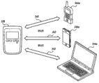
Fig. 1 is according to the schematic diagram of the system of embodiment of the present disclosure;
Fig. 2 A is the schematic diagram of the operation of the main equipment in the system shown in Fig. 1;
Fig. 2 B is described in the discovery of the system shown in Fig. 2 A and the process flow diagram of bindings according to embodiment of the present disclosure;
Fig. 3 is according to the front view of the main equipment of embodiment of the present disclosure;
Fig. 4-7th, according to the exemplary embodiment of the system of embodiment of the present disclosure;
Fig. 8 is according to the schematic diagram of the operation of the gateway system of another embodiment of the present disclosure; And
Each embodiment according to the gateway system of embodiment of the present disclosure has been described in Fig. 9-11.
Embodiment
Embodiment of the present disclosure for example relates generally to, by hand system, individual component and the method for carrying out measurement parameter (electric, machinery and physical measurement parameter) with this system, parts.The embodiment describing in the application may be at a plurality of measurement parameters at a plurality of diverse locations place for testing or monitoring, and some position is even at closure panel or interlocking back.
Before the details of various aspects of the present disclosure is discussed, should understands one or more part as described below and can embody with logic and the operation that can be carried out by conventional electronic component.These electronic units that can be aggregated to single position or large area distribution generally include controller, microcontroller, control module, processor, microprocessor etc.It will be understood to those of skill in the art that any logic that the application describes can with comprise hardware, software with and the various configurations of combination implement, but be not limited to this.Hardware can comprise mimic channel, digital circuit, processing unit, special IC (ASICs) etc. with and combination, but be not limited to this.In the environment of the parts of the system that distributed, parts can the access each other via communication line.
Although illustrated and described some embodiment, should be appreciated that and can carry out various modifications to these embodiment, and do not depart from spirit and scope of the present disclosure.Each embodiment that the disclosure is described is only provided as example or explanation, and should not be understood to preferably or more have superiority with respect to other embodiment.The exemplary embodiment that the application provides is not intended to exclusive or the disclosure is limited to disclosed precise forms.In addition, be to be appreciated that embodiment of the present disclosure can adopt the combination in any of the feature that the application describes.
As what can see from Fig. 1 and Fig. 2, embodiment of the present disclosure relates to a kind of for obtaining and the system 20 of display measurement parameter.System 20 comprises a plurality of hand-held or portable measuring equipments.For example, system 20 comprises main equipment 22 and at least one utility appliance 24.In embodiment of the present disclosure, main equipment 22 can carry out the first measurement, and utility appliance 24 can be carried out the second measurement and the second measurement result is sent to main equipment 22.
An advantage of the embodiment that the application describes is that user can operate system of the present disclosure, with in region long-range or that be difficult to arrive (for example, at machine or the interlocking back side) measure.In this respect, at least one utility appliance 24 can be far away apart from main equipment 22, to test or to monitor at least one second parameter.Therefore, main equipment 22 not only can be tested or monitor the first parameter and user is shown to result data, and main equipment 22 can also receive data also for user is presented at these data main equipment 22 from utility appliance 24.Therefore the system 20 that, the application describes is not by needing user to simplify user's work to the position reading out data of utility appliance 24.
Although system 20 is illustrated and be described as to comprise main equipment 22 and utility appliance 24, yet it should be understood that the equipment can with any amount measures and measurement result is sent to main equipment 22 in system 20.In at least one embodiment of the present disclosure, system 20 can comprise up to ten separate devices.In embodiment of the present disclosure, system 20 can comprise nearly 20 separate devices.In another embodiment of the present disclosure, system 20 can comprise a separate devices arbitrarily.As hereinafter will be in greater detail, in the system 20 comprising more than two equipment, system 20 be configured to utilize one-to-many (or " star ") configuration to communicate with main equipment 22.
Hand system as described in the present application or equipment comprise that the hand that is conventionally configured to user can catch one or more equipment of simultaneously measuring.Yet, it should be understood that system or equipment is not must be held in user's hand, but can for example by system or equipment is fixed or is suspended on support member or machine, orientate as and not be held by user.
Still with reference to figure 1 and Fig. 2, main equipment 22 can be main process equipment.In this respect, main equipment 22 can be configured to collect each equipment from system 20, for example, from utility appliance 24(or from a plurality of module devices) data that receive.In addition, main equipment 22 can be for independently carrying out one or many measurement and collecting the test facilities of data from this measurement result.As hereinafter will be in greater detail, main equipment 22 can also comprise for showing the display 30 of data, and no matter these data are that other equipment from system 20 are collected or are measured by main equipment 22.
In embodiment of the present disclosure, main equipment 22 is multimeters, and hand-held digital multimeter for example, as shown in can be in the embodiment show in figure 3.In this respect, main equipment 22 can be that one or more measurement functions are combined in to an electronic surveying facility in unit.As non-limiting example, main equipment 22 can carry out multiple measurement, and for example DC voltage, AC voltage, resistance, continuity and electric current, as shown in a plurality of rotary switches 182 positions in the exemplary embodiment of Fig. 3.
With reference to the schematic diagram of figure 2A, existing by the parts of more detailed description main equipment 22.Main equipment 22 can comprise various parts, described parts comprise that I/O (I/O) interface 28(for example comprises display 30 and for the input interface 36 of user input), for the measuring system 32 measured, for receiving and/or send the first communication system 34, CPU (central processing unit) (CPU) or the processor 38 of information and for the storage system 40 of the information of storing.Main equipment 22 can also comprise optional second communication system 42.
According to the customized configuration of equipment and type, storage system 40 can comprise the system storage of volatibility or nonvolatile memory form, for example ROM (read-only memory) (" ROM "), random access memory (" RAM "), EEPROM, flash memory or other memory technologies.Those skilled in the art and other staff will recognize, the common storage of system storage can be understood and is linked into processor 38 and/or the current data that just operated by processor 38 and/or program module.In this respect, processor 38 is used as the computing center of main equipment 22 by the execution of support program instruction.
Storer can also comprise storage-type storer.Storage-type storer can be any volatibility or non-volatile, the removable or irremovable storage device of implementing by any technology that can store information.The example of storage-type storer includes but not limited to hard disk drive, solid-state drive, CD ROM, DVD or other jukebox storages, tape cassete, tape, magnetic disk memory etc.In storage-type storer, canned data can include but not limited to program module and the data by processor 38 accesses.Generally speaking, program module can comprise the routine carrying out particular task or implement particular abstract data type, application, object, parts, data structure etc.It should be understood that system storage and storage-type storer that the application describes are only the example of various computer-readable recording mediums.
Storage system 40 can also be configured to the information that the measuring system of storage from the measuring system 32 of main equipment 22 and the utility appliance 24 that receives by communication system 34 receives.When receiving information in storage system 40, processor 38 can be configured to carry out instruction, directly to show on display 30 from measuring system 32 or the information that receives from the first communication system 34.
For user and main equipment 22 carry out alternately, I/O interface 28 can comprise a plurality of parts, and described parts can obtain input and output is offered to the miscellaneous part in user and/or system 20 by the miscellaneous part from user and/or system 20 processor 38.Although be depicted as in the exemplary embodiment, comprise keyboard 36 and display 30, yet I/O interface 28 can include but not limited to display such as LCD, LPD, OLED display and keyboard, hard manual or soft keyboard, touch pad, controller, physical button, roller, digital pen, tracking ball, control lever etc.In at least one embodiment, display 30 can configure the interface as I/O, touch-screen for example, and do not need independent keyboard 36.I/O interface 28 can also receive input from one or more utility appliance 24, and output can be offered to one or more utility appliance 24 in certain embodiments.
Still with reference to figure 2A, the first communication system 34 comprises uses the one or more parts (as what can see at Fig. 1) that communicate with one or more discrete utility appliance 24 for sending and/or receive the suitable wired or wireless communication agreement (including but not limited to USB, WiFi or bluetooth) of information.In embodiment of the present disclosure, information is for example used proprietary communication protocol from utility appliance 24, to send to main equipment 22 by radio signal in system 20.
In addition, main equipment 22 can comprise for independent computing equipment (for example, such as the mobile computing device of dull and stereotyped phone or smart phone, personal computing devices, portable computing device, personal digital assistant etc.) the added communications circuit that communicates, for example second communication system 42.Telecommunication circuit can comprise for the modulator-demodular unit in one or more network executive communications, transmitter/receiver and/or transceiver circuit.In order to carry out radio communication, the telecommunication circuit of the first system 34 or second system 42 can comprise one or more suitable antenna (not shown).For the ease of illustrating, Fig. 2 A does not describe typical case is included in to analog to digital converter in telecommunication circuit, digital to analog converter, amplifier, device controller etc.Yet owing to being included in, these and other parts in telecommunication circuit are known in the art, thereby will be not described in detail in the present invention.
In certain embodiments, main equipment 22 can be configured to communicate with computing equipment, and comprises the communication facilities that can be coupled via near field agreement, infrared protocol, Bluetooth protocol, IEEE802 agreement, the wired connection that connects etc. such as USB, Ethernet or RS232.
In certain embodiments, when main equipment 22 is positioned near utility appliance 24, I/O interface 28 allows main equipments 22 wirelessly to bind or be coupled to utility appliance 24, as hereinafter will be in greater detail.In this respect, utility appliance 24 also comprises the communication system 64 that is configured to be coupled with main equipment 22 and sends signal to main equipment 22, and it comprises transmitter, transceiver and/or analog.
In the time of near main equipment 22 is positioned at utility appliance 24, the first communication system 34 can be carried out and find and binding processing, thereby main equipment 22 can receive one or more signals from utility appliance 24, thereby main equipment 22 is carried out associated with utility appliance 24.Discovery and binding processing can be automatically or be started by user via switch, graphical user interface elements etc.In a non-limiting example, main equipment 22 and utility appliance 24 are configured to via proprietary radio signal pairing.
Once coupling, main equipment 22 can be configured to receive measurement data from utility appliance 24 by I/O interface 28.Measurement data can provide to main equipment 22 from utility appliance 24 via radio communication or by other communication network.Particularly, utility appliance 24 is configured to provide to main equipment 22 measurement data or other data that generated by utility appliance 24.
Forward now Fig. 3 to, according to an embodiment of the present disclosure, provide the exemplary embodiment of main equipment 122.Display 130 is configured to show to come the measurement result of autonomous device 122 and utility appliance (also not shown in Fig. 3).For example, with reference to figure 3, display 130 comprises that the first measured value 150 and the first measurement type indication 152(reading are respectively " 465.2 " and " V AC ").In the embodiment shown, measurement type indication 152 is corresponding with the measurement type of selecting on rotary switch 182.In addition, display 130 comprises that second measured value 154 corresponding with measurement result from utility appliance and second measure type indication 156(reading and be respectively " 466.5 " and " V AC ").The second measured value 154 is indicated by indicator 158, is depicted as " 1 " of black matrix printing.
In the embodiment shown, display 130 on main equipment 122 also comprises that the 3rd measured value 160 and the 3rd measures type indication 162(reading and be respectively " 74.3 " and " F "), and the 4th measured value 164 and the 4th is measured type and is indicated 166(reading to be respectively " 25.6 " and " A AC ").The 3rd measured value 160 and the 4th measured value 164, by indicator 168 and 170 indications, are shown as " 2 " and " 3 " of black matrix, and receive from binding or be coupled to the additional utility appliance of main equipment 122.As described above, the display 130 on main equipment 122 can be configured to show the metrical information from the different utility appliance of any amount.
For the indicator 158,168 of a plurality of utility appliance and 170, for each of a plurality of utility appliance, be customizable configuration, for user's indication of simplifying.In this respect, indicator 158,168 and 170 can comprise character or the symbol of any amount.
As what can find out in the embodiment show in figure 3, display 130 can also be configured to show other information except metrical information about system 120, for example dangerous voltage of measuring 172 of main equipment 122, risk 174, data transfer state 176 and battery status 178.Display 130 can also be configured to comprise other information, for example main equipment 122 or arbitrarily utility appliance (such as what determined by GPS) ad-hoc location, arbitrarily the battery status of utility appliance, the title of utility appliance or identification information or from any other information or the measurement parameter of utility appliance arbitrarily.The information illustrating on display 130 can include but not limited to main equipment battery status, utility appliance battery status, utility appliance data entry state, utility appliance data transmission state, master identification, utility appliance sign, the GPS position of main equipment, the GPS position of utility appliance, main equipment data, utility appliance data etc.
In the embodiment shown, I/O interface 128 comprises keyboard 180, rotary switch 182 and the measuring system 132 for input message.In the embodiment shown, keyboard 180 comprises a plurality of buttons for various difference in functionalitys, comprise standard digital multimeter button, for example " HOLD ", " MINMAX ", " RANGE " and " SHIFT ", and non-standard wireless function button 184,186 and 188.For example, can press radio button 184 main equipment 22 be set as to open communication circuit 34 and start module discovery procedure, to find utility appliance 24, as described in more detail below." discovery " after utility appliance 24, user can use " SELECT " button 186, with by utility appliance 24 and main equipment 22 bindings (or not binding).Scroll button 188 is used between each " found " utility appliance 24 and rolls.
As mentioned above, rotary switch 182 comprises for measuring the exemplary selection of DC voltage, AC voltage, resistance, continuity and electric current, as shown in a plurality of position of a rotary switch in Fig. 3.Yet, it should be understood that rotary switch 182 can be for selecting the measurement parameter of any type.In addition, rotary switch 182 also comprises " OFF " position, to stop measuring also closing device.
The measurement interface 132 of measuring facility for connecting comprises for connecting the various terminals of facility to measure.In the embodiment shown, terminal comprises it can being the first terminal 190 for the input of current measurement and power frequency, can be second terminal 192 that returns to terminal of all appts and can be the 3rd terminal 194 of the input of measuring for voltage, resistance, diode, electric capacity and electric voltage frequency.
Return to Fig. 1 and Fig. 2, will describe in more detail utility appliance 24 now.Utility appliance 24 in fact can be similar with main equipment 22, or can be different from main equipment 22.In this respect, utility appliance 24 can be the same numbers multimeter shown in Fig. 3, can be maybe the utility appliance of another kind of testing tool, for example thermal module (with reference to figure 4), pincerlike meter (with reference to figure 5 and Fig. 6) or flexible current probe machine (with reference to figure 7).
The measurement that utility appliance 24 is carried out can be electric, mechanical, physics or other parameter, the calculated value that includes but not limited to voltage, electric current, vibration, resistance, electric capacity, inductance, frequency, temperature, relative humidity, magnetic field, flow velocity, moisture, per minute rotating speed, pressure, distance, light, infrared contact, decibel and draw from main measurement result (for example watt, power quality, peak factor and dutycycle).
Return to the shown embodiment of Fig. 2 A, utility appliance 24 comprises various parts, described parts comprise that I/O (I/O) interface 58(for example comprises selectable display 60 and for the input interface 66 of user input), for the measuring system 62 measured, for receiving and/or send communication system 64, CPU (central processing unit) (CPU) or the processor 68 of information and for the storage system 70 of the information of storing.Utility appliance 24 does not need display 60, but can comprise display yet.Parts and the above-mentioned parts of describing with reference to main equipment 22 are basic identical, therefore, except difference part, will again not be described.
In order to start according to an embodiment discovery procedure of the present disclosure, user can activate the communications buttons 184 and 284 in each of each main equipment 22 and utility appliance 24.For example,, with reference to the piece 80 and 84 in the process flow diagram of figure 2B.In the embodiment show in figure 3, during discovery procedure, send status identifier 176 and may be displayed on main equipment.When being activated, main equipment 22 is listened to the signal (for example, with reference to the piece 86 in the process flow diagram of figure 2B) that periodically utility appliance 24 of (for example every five seconds) transmitted signal sends.The signal that utility appliance 24 sends can be digital signal, current demand signal or another signal (for example, with reference to the piece 82 in the process flow diagram of figure 2B).
When main equipment 22 is found utility appliance 24 (for example, with reference to the piece 88 in the process flow diagram of figure 2B), identifier can appear on main equipment 22.For example, the module of utility appliance 24 numbering can appear on the display 30 of main equipment 22.After finding, main equipment 22 can be configured to and utility appliance 24 bindings.In an embodiment of the present disclosure, utility appliance 24 can be bound automatically with main equipment 24.In another embodiment, user can press " SELECT " button 186 so that utility appliance 24 and main equipment 22 are bound.Similarly, user can press " SELECT " button 186 again cancel to select utility appliance 24(for example with reference to the piece 90 in the process flow diagram of figure 2B), thus the communicating by letter of releasing or release utility appliance 24 and main equipment 22.If had been found that a plurality of utility appliance 24, user can use scroll button 188 to roll between the utility appliance 24 different.
In embodiment of the present disclosure, binding procedure for example can wake utility appliance 24(up, if utility appliance 24 is in sleep pattern) and set up communication, make from property information cycle of utility appliance 24 send to main equipment 22.In this respect, main equipment 22 can solicited message, and for example, from the measurement data of utility appliance 24, and utility appliance 24 can send to this information main equipment 22(for example with reference to the piece 92 and 94 in the process flow diagram of figure 2B).For example, if utility appliance 24 is configured to carry out for every 20 seconds one-shot measurement,, when producing this measurement data, this measurement data can be sent to main equipment 22.This information can also be illustrated on the display on main equipment 22, for example data 154 and the data type 156 of the identifier 158 of utility appliance 24, reception.
For by the utility appliance of main equipment 22 and one or more bindings 24 unbinds, the radio of any in main equipment 22 or utility appliance 24 can be closed.Alternatively, main equipment 22 can be configured to simply utility appliance 24 unbinds, or main equipment 22 can leave the communication range with utility appliance 24 simply.If main equipment 22 and utility appliance 24 unbinds, however the radio of utility appliance 24 is preserved for communication measurement data, and utility appliance 24 can be proceeded measure and store data in its storage system 240.When again binding, utility appliance 24 can be configured to the data of all storages to send to the main equipment 22 of its binding.
In embodiment of the present disclosure, system 20 comprises single-ended binding procedure, makes utility appliance 24 be configured to communicate with main equipment 22, wherein by only activating main equipment, main equipment 22 and utility appliance 24 is bound automatically.In this respect, utility appliance 24 can utilize its discovery feature having activated to be set in appropriate position, makes periodically (for example every five seconds) transmitted signal of utility appliance 24.User can enter after several hours or several days to be had the region of main equipment 22 and can activate the discovery button 284 on main equipment.If main equipment 22 has been found utility appliance 24, main equipment can unilaterally be selected the utility appliance 24 for binding, thus the communication link of foundation and utility appliance 24.Need to pairing in advance between specific master 22 and utility appliance 24.User can only have to the physical contact of main equipment 22 rather than utility appliance 24.After binding, user then can use main equipment 22 to measure and receive data from utility appliance 24.
The utility appliance 24 that it will also be appreciated that the system 20 that the application describes can be configured to for opening binding, and wherein, a plurality of main equipments 22 can be bound with identical utility appliance 24.Therefore, the first technician can measure and read measurement result from one or more utility appliance 24 with his main equipment 22, and second technician with its oneself main equipment 22 for example also can with after utility appliance 24 unbinds measure and read measurement result from utility appliance 24 at the first equipment 22.When main equipment 22, lose or damage and must change maybe when having the position of technician access system 20 of different main equipment instruments, this configuration is particularly useful.In addition, because system 20 is modular, thereby if needed, in primal system 20, can add always or replace the utility appliance 24 of measuring for extra.
In embodiment of the present disclosure, system 20 can be configured such that utility appliance 24 can be at every turn only with 22 bindings of a main equipment.When unbind, utility appliance 24 can be bound with another main equipment 22.Utilize this configuration, greatly reduce the possibility that user obscures or misread utility appliance.
In another embodiment of the present disclosure, when main equipment 22 and utility appliance 24 communicate with one another via communication link, system 20 can generate signal.For example, when utility appliance 24 is communicated by letter with main equipment 22, utility appliance 24 can generate vision, vibration or audible signal.In addition, main equipment 22 can also generate the signal that represents the utility appliance 24 communicate by letter with this main equipment 22.For example, with reference to figure 3, when main equipment 22 is communicated by letter with the utility appliance 24 that is designated " 1 ", can highlight the identification marking symbol 158 that maybe can start in stroboscopic display 130.
With reference to figure 1, as described above, system 20 is set in one-to-many communication network, main equipment 22 is directly communicated by letter with each utility appliance 24.Compare with the mesh communication network that each separate devices communicates with a plurality of other equipment in network, the communication network of system 20 is more limited in its coverage, but needs significantly lower power than mesh communication network.In an embodiment of the present disclosure, main equipment 22 is less than approximately 100 meters with the radius of communicating by letter between utility appliance 24.In another embodiment of the present disclosure, main equipment 22 is less than approximately 20 meters with the radius of communicating by letter between utility appliance 24.
In view of the power demand of the reduction of communication network, main equipment 22 can rely on utility appliance 24 battery-powered operation that at least continues 100 hours.Yet, it should be understood that battery life depends on the kind of used battery, utilizes the kind of test that system carries out, the operative configuration of the quantity of the battery in system and the equipment in system.In system, the expected life of each equipment can change, and for example main equipment can have the expected life different from utility appliance.Other power management features of system comprise sleep (non-communication) pattern and the periodical communication (for example once communicating by letter for every five seconds in utility appliance) of equipment.
Now by the operation of descriptive system 20.The utility appliance 24 of the one or more suitable types of user by selecting, they are placed on to appropriate position and they are set as measuring to arrange system 20 with respect to the machine that will test.Utility appliance 24 for example finds by pressing that button 284 is opened, setting measurement and be set as communication pattern (with reference to figure 4-7).As described above, when being activated in order to communicate by letter, utility appliance 24 sends and can receive by main equipment 22 cyclical signal of (or discovery).
User then opens main equipment 22 and is set as measuring special parameter.User also for example activates its discovery mode (with reference to figure 3) by pressing the discovery button 284 of main equipment 22.When main equipment 22 finds one or more utility appliance 24, user is tied to main equipment 22 by one or more utility appliance 24, and starts from described one or more utility appliance 24 receiving cycle data.This data can be seen on the display 30 of main equipment 22.
With reference now to Fig. 8-11,, by about comprising that the system of gateway device describes another embodiment of the present disclosure.It should be understood that the parts of gateway system embodiment of Fig. 8-11 are except about communication with measure the difference of feature, similar with a plurality of parts of the embodiment of Fig. 1-7 of describing in advance in material and operation, as hereinafter will be in greater detail.For the purpose of clearer in the following description, the Reference numeral of the like of the system 20 of describing in the embodiment of Fig. 1-7 is for describing the system 320 of Fig. 8-11, except using the numeral with 300 digit sequences.
With reference to figure 8, according to an embodiment of the present disclosure, provide the schematic diagram of the system 320 that comprises gateway device 322.As described above, gateway system 320 substantially can be similar with said system 20.Similarly, gateway 322 except gateway 322 may not be the measuring equipment that is configured to measure, material and operation on substantially can be similar with above-mentioned main equipment 22.
The parts of gateway device 322 can comprise various parts, described parts comprise that I/O (I/O) interface 328(for example comprises selectable display 330 and for the input interface 336 of user input), for from utility appliance 324, receive and/or the first communication system 334, CPU (central processing unit) (CPU) or the processor 338 of the information of transmission, for the storage system 340 of the information of storing and for receiving and/or send information to local computing device 344a or the second communication system 342 to remote computing device via the Internet 344b or local network 344c.Different from main equipment 22, gateway device 322 can not measured.
The first communication system 334 can be for sending and/or receive the suitable wired or wireless communication agreement of information.In an embodiment of the present disclosure, information is for example used proprietary protocol from utility appliance 324, to send to gateway device 322(for example with reference to figure 9 by radio signal in system 20).Therefore, gateway device 322 is configured to receive at least one signal of communication (for example at least one radio signal) that comprises direct at least one measured value from least one measuring equipment 324.
Similar with above-mentioned main equipment 22, gateway device 322 can also be configured to have single binding system.In this respect, utility appliance 324 can be configured to by only coming to communicate with gateway device 322 with the binding that gateway device 322 activates between gateway device 322 and utility appliance 24.For unbind, gateway device 322 can be activated to discharge utility appliance 324, or the utility appliance 324 of gateway device 322 or binding arbitrarily can be de-energized simply.
According to an embodiment of the present disclosure, the hand-held measuring equipment of a kind of main frame generally includes:
Measuring system, it is configured to measure the first parameter and determines the first measured value; And
Receiving system, it is configured at least from independent measurement equipment, receive the second measured value, and wherein, described the second measured value is determined by the measuring system of measuring in the described independent measurement equipment of the second parameter.
In any embodiment of describing in the application, described main process equipment can comprise the display on described main process equipment, at least showing described the first measured value and described the second measured value.
In any embodiment of describing in the application, described main process equipment can be digital multimeter.
In any embodiment of describing in the application, described the first parameter can be selected from the group of following every formation: voltage, electric current, vibration, resistance, electric capacity, inductance and frequency.
In any embodiment of describing in the application, described the second parameter can be selected from the group of following every formation: voltage, electric current, vibration, resistance, electric capacity, inductance, frequency, temperature, relative humidity, decibel, magnetic field, flow velocity, moisture, rotating speed, pressure, distance, light and infrared contact.
In any embodiment of describing in the application, described main process equipment can be configured to use the communication link of single-ended binding procedure foundation and described independent measurement equipment, make described independent measurement equipment be configured to communicate by letter with described main process equipment, wherein, by only activating described the main process equipment described main process equipment of binding and described autonomous device automatically.
In any embodiment of describing in the application, described main process equipment can be configured to control described independent measurement equipment.
In any embodiment of describing in the application, described main equipment can not be configured to control described independent measurement equipment.
In any embodiment that the application describes, the communication range between described main process equipment and described independent measurement equipment can have from by be less than approximately 100 meters be less than the radius of selecting in approximately 20 meters of groups that form.
In any embodiment of describing in the application, described main process equipment can be configured to be generated in response to the communication link between the described main process equipment being established and described independent measurement equipment user's signal.
In any embodiment that the application describes, by the demonstration of described main process equipment and/or the definite measured value of described independent measurement equipment, can be configured to identify for the user's of described main process equipment customization.
In any embodiment that the application describes, described receiving system can be configured to from carrying out a plurality of measurements and a plurality of independent measurement equipment that described a plurality of measured values send to described main process equipment are received to measured values.
In any embodiment of describing in the application, described receiving system can be configured to communicate in one-to-many network.
In any embodiment of describing in the application, described main process equipment can be configured to show described the first measured value and described the second measured value on described main process equipment.
According to another embodiment of the present disclosure, a kind of hand held module equipment is provided, described equipment generally includes:
Measuring system, it is for measuring the first parameter and determining the first measured value; And
Communication system, it is configured to described the first measured value to send to the unique host measuring equipment that can measure the second parameter, wherein, by only activating described main frame measuring equipment, automatically set up the communication link between described main frame measuring equipment and described communication system.
In any embodiment of describing in the application, the described communication system of described module device can be configured to signal period property to send to described main frame measuring equipment.
In any embodiment of describing in the application, described module device can comprise the display on described module device, at least showing described the first measured value.
In any embodiment of describing in the application, described module device can not comprise display.
In any embodiment of describing in the application, described module device can be digital multimeter.
In any embodiment of describing in the application, described the first parameter can be selected from the group of following every formation: voltage, electric current, vibration, resistance, electric capacity, inductance, frequency, temperature, relative humidity, decibel, magnetic field, flow velocity, moisture, rotating speed, pressure, distance, light and infrared contact.
In any embodiment of describing in the application, described module device can be controlled by described main frame measuring equipment.
In any embodiment of describing in the application, described module device can independently be controlled.
In any embodiment that the application describes, the communication range between described main frame measuring equipment and described module device can have from by be less than approximately 100 meters be less than the radius of selecting in approximately 20 meters of groups that form.
In any embodiment of describing in the application, described module device can be configured to generate the signal that information is sent to user, and wherein, described signal is visual signal, vibration signal or audible signal.
In any embodiment of describing in the application, described module device can be configured to the customization identification for described main frame measuring equipment.
In any embodiment of describing in the application, described module device can comprise the second measuring system, it is for measuring the second parameter and determining the second measured value, and wherein, described communication system is also configured to send described the second parameter value to described main frame measuring equipment.
According to another embodiment of the present disclosure, a kind of method of using hand held module device measuring parameter is provided, the method generally includes:
By activating unique host measuring equipment, activate the communication link between described module device and described unique host measuring equipment;
Use described module device to measure the first parameter and determine the first measured value; And
Described the first measured value is sent to described main frame measuring equipment, for the second measured value that shows that on described main frame measuring equipment described main frame measuring equipment is determined.
According to another embodiment of the present disclosure, a kind of hand system for measurement parameter is provided, described system comprises:
Main handheld device, it is configured to measure the first parameter and determines the first measured value; And
Nondominant hand holding equipment, it is configured to measure the second parameter and determines the second measured value, and wherein, described nondominant hand holding equipment is also configured to send described the second measured value to described main handheld device.
In any embodiment of describing in the application, described main handheld device can be digital multimeter.
In any embodiment of describing in the application, described the first parameter can be selected from the group of following every formation: voltage, electric current, vibration, resistance, electric capacity, inductance and frequency.
In any embodiment of describing in the application, described the second parameter can be selected from the group of following every formation: voltage, electric current, vibration, resistance, electric capacity, inductance, frequency, temperature, relative humidity, decibel, magnetic field, flow velocity, moisture, rotating speed, pressure, distance, light and infrared contact.
In any embodiment of describing in the application, described main handheld device can also comprise display, at least showing described the first measured value and described the second measured value.
In any embodiment of describing in the application, described nondominant hand holding equipment can comprise display.
In any embodiment of describing in the application, described nondominant hand holding equipment can not comprise display.
In any embodiment of describing in the application, described main handheld device can be configured to use the communication link of single-ended binding procedure foundation and described nondominant hand holding equipment, make described nondominant hand holding equipment be configured to communicate by letter with described main handheld device, wherein, by only activating described main handheld device, automatically bind described main handheld device and described nondominant hand holding equipment.
In any embodiment of describing in the application, described main handheld device can be configured to control described nondominant hand holding equipment.
In any embodiment of describing in the application, described nondominant hand holding equipment can be controlled self.
In any embodiment that the application describes, the communication range between described main handheld device and described nondominant hand holding equipment can have from by be less than approximately 100 meters be less than the radius of selecting in approximately 20 meters of groups that form.
In any embodiment of describing in the application, described utility appliance can be configured to generate the signal that information is sent to described user, and wherein, described signal is visual signal, vibration signal or audible signal.
In any embodiment of describing in the application, described main handheld device can be configured to be generated in response to the communication link between the described main equipment being established and described nondominant hand holding equipment user's signal.
In any embodiment that the application describes, by the demonstration of described main handheld device and/or the definite measured value of described nondominant hand holding equipment, can be configured to identify for the user's of described main handheld device customization.
In any embodiment of describing in the application, described system can also comprise additional nondominant hand holding equipment, it is configured to measure the 3rd parameter and determines the 3rd parameter value, and wherein, described additional nondominant hand holding equipment is also configured to described the 3rd measured value to send to described main handheld device.
In any embodiment of describing in the application, described main handheld device can be configured to communicate with described nondominant hand holding equipment in one-to-many network.
According to another embodiment of the present disclosure, a kind of hand system for measurement parameter is provided, described system generally includes:
Main equipment, can carry out the first measurement; And
Utility appliance, can carry out the second measurement and the second measurement result is sent to described main equipment,
Wherein, described main equipment is configured to use the communication link of single-ended binding procedure foundation and described utility appliance, make described utility appliance be configured to communicate with described main equipment, wherein, by only activating described main equipment, automatically bind described main equipment and described utility appliance.
According to another embodiment of the present disclosure, a kind of method of using hand system measurement parameter is provided, described method comprises:
Use main handheld device to carry out the first measurement, wherein, the first measurement result is electric, machinery or physical parameter;
Use nondominant hand holding equipment to carry out the second measurement;
The second measurement result is sent to described main handheld device; And
By described the first measurement result and described the second measurement result, the two is presented on the display of described main handheld device.
According to another embodiment of the present disclosure, a kind of method of using hand system measurement parameter is provided, described method comprises:
By only activating main handheld device, described nondominant hand holding equipment is tied to described main handheld device, automatically to set up the communication link between described main handheld device and described nondominant hand holding equipment;
Use described main handheld device to carry out the first measurement;
Use nondominant hand holding equipment to carry out the second measurement; And
The second measurement result is sent to described main handheld device.
Although illustrated and described each illustrative examples, yet it should be understood that and can change it, and do not depart from spirit and scope of the present disclosure.
Claims (16)
1. the hand-held measuring equipment of main frame, comprising:
Measuring system, it is configured to measure the first parameter and determines the first measured value; And
Receiving system, it is configured at least from independent measurement equipment, receive the second measured value, and wherein, described the second measured value is determined by the measuring system of measuring in the described independent measurement equipment of the second parameter.
2. main process equipment according to claim 1, also comprises the display on described main equipment, and it is at least showing described the first measured value and described the second measured value.
3. main process equipment according to claim 1, wherein, described main process equipment is digital multimeter.
4. main process equipment according to claim 1, wherein, described the first parameter is selected from the group of following every formation: voltage, electric current, vibration, resistance, electric capacity, inductance and frequency.
5. main process equipment according to claim 1, wherein, described the second parameter is selected from the group of following every formation: voltage, electric current, vibration, resistance, electric capacity, inductance, frequency, temperature, relative humidity, decibel, magnetic field, flow velocity, moisture, rotating speed, pressure, distance, light and infrared contact.
6. main process equipment according to claim 1, wherein, described main process equipment is configured to use the communication link of single-ended binding procedure foundation and described independent measurement equipment, make described independent measurement equipment be configured to communicate with described main process equipment, wherein, by only activating described main process equipment, automatically bind described main equipment and described autonomous device.
7. main process equipment according to claim 1, wherein, described main process equipment is configured to control described independent measurement equipment.
8. main process equipment according to claim 1, wherein, described main process equipment is not configured to control described independent measurement equipment.
9. main process equipment according to claim 1, wherein, the communication range between described main process equipment and described independent measurement equipment has from by being less than approximately 100 meters and be less than the radius of selecting in approximately 20 meters of groups that form.
10. main process equipment according to claim 1, wherein, described main process equipment is configured to generate the signal to user in response to the communication link between set up described main process equipment and described independent measurement equipment.
11. main process equipments according to claim 1, wherein, can be configured to identify for the user's of described main process equipment customization by the demonstration of described main process equipment and/or the definite measured value of described independent measurement equipment.
12. main process equipments according to claim 1, wherein, described receiving system is configured to from carrying out a plurality of measurements and a plurality of independent measurement equipment that a plurality of measured values send to described main process equipment are received to measured values.
13. main process equipments according to claim 12, wherein, described receiving system is configured to communicate in one-to-many network.
14. 1 kinds of methods of using the hand-held measuring equipment of main frame to carry out measurement parameter, described method comprises:
By the hand-held measuring equipment of described main frame, measure the first parameter, and determine the first measured value; And
By the hand-held measuring equipment of described main frame, from independent measurement equipment, receive the second measured value, wherein, described the second measured value is determined by the described independent measurement equipment of measuring the second parameter.
15. 1 kinds of hand held module equipment, described equipment comprises:
Measuring system, it is for measuring the first parameter and determining the first measured value; And
Communication system, it is configured to described the first measured value to send to the unique host measuring equipment that can measure the second parameter, wherein, by only activating described main frame measuring equipment, automatically set up the communication link between described main frame measuring equipment and described communication system.
16. 1 kinds of hand systems for measurement parameter, it comprises main process equipment according to claim 1 and module device according to claim 15, described system comprises:
Main handheld device, it is configured to measure the first parameter and determines the first measured value; And
Nondominant hand holding equipment, it is configured to measure the second parameter and determines the second measured value, and wherein, described nondominant hand holding equipment is also configured to send described the second measured value to described main handheld device.
Applications Claiming Priority (6)
| Application Number | Priority Date | Filing Date | Title |
|---|---|---|---|
| US201261679652P | 2012-08-03 | 2012-08-03 | |
| US61/679,652 | 2012-08-03 | ||
| US201261707804P | 2012-09-28 | 2012-09-28 | |
| US61/707,804 | 2012-09-28 | ||
| US13/830,556 | 2013-03-14 | ||
| US13/830,556 US20140035607A1 (en) | 2012-08-03 | 2013-03-14 | Handheld Devices, Systems, and Methods for Measuring Parameters |
Publications (1)
| Publication Number | Publication Date |
|---|---|
| CN103575329A true CN103575329A (en) | 2014-02-12 |
Family
ID=48948238
Family Applications (1)
| Application Number | Title | Priority Date | Filing Date |
|---|---|---|---|
| CN201310334993.1A Pending CN103575329A (en) | 2012-08-03 | 2013-08-02 | Handheld devices, systems, and methods for measuring parameters |
Country Status (4)
| Country | Link |
|---|---|
| US (1) | US20140035607A1 (en) |
| EP (1) | EP2693222A1 (en) |
| JP (1) | JP2014032677A (en) |
| CN (1) | CN103575329A (en) |
Cited By (4)
| Publication number | Priority date | Publication date | Assignee | Title |
|---|---|---|---|---|
| CN105548650A (en) * | 2014-10-27 | 2016-05-04 | 弗兰克公司 | Flexible current sensor |
| CN107079252A (en) * | 2014-09-10 | 2017-08-18 | 乐高公司 | Method for setting up wireless connection between electronic installation |
| CN112485476A (en) * | 2020-11-19 | 2021-03-12 | 国网四川省电力公司广元供电公司 | Multifunctional clamp meter device and system |
| US11262899B2 (en) | 2014-09-10 | 2022-03-01 | Lego A/S | Method for establishing a functional relationship between input and output functions |
Families Citing this family (28)
| Publication number | Priority date | Publication date | Assignee | Title |
|---|---|---|---|---|
| CN204214925U (en) * | 2012-03-16 | 2015-03-18 | 菲力尔系统公司 | Electric transducer and electric transducer label |
| US10095659B2 (en) | 2012-08-03 | 2018-10-09 | Fluke Corporation | Handheld devices, systems, and methods for measuring parameters |
| US9377485B2 (en) * | 2013-03-15 | 2016-06-28 | Fluke Corporation | Handheld measurement system with selectable options |
| JP6449232B2 (en) * | 2013-03-15 | 2019-01-09 | フルークコーポレイションFluke Corporation | Automatic recording and graphing of measurement data |
| US9766270B2 (en) | 2013-12-30 | 2017-09-19 | Fluke Corporation | Wireless test measurement |
| FR3019301B1 (en) * | 2014-03-25 | 2018-02-09 | Societe Anonyme Des Ets Catu | ELECTRIC MEASURING AND CONTROL APPARATUS |
| DE202014007077U1 (en) * | 2014-09-04 | 2015-12-08 | EurA Consult AG | Clamp Meter |
| JP6094562B2 (en) | 2014-11-06 | 2017-03-15 | 横河電機株式会社 | Recorder |
| CN106501556A (en) * | 2015-09-06 | 2017-03-15 | 福禄克公司 | Measurement apparatus and measuring method |
| DK3139180T3 (en) | 2015-09-07 | 2021-02-01 | Ikalogic S A S | WIRELESS PROBE FOR MEASURING ELECTRICAL SIGNALS, OSCILLOSCOPE SYSTEM AND MEASUREMENT METHOD USING THE SYSTEM |
| US10119998B2 (en) | 2016-11-07 | 2018-11-06 | Fluke Corporation | Variable capacitance non-contact AC voltage measurement system |
| US10139435B2 (en) | 2016-11-11 | 2018-11-27 | Fluke Corporation | Non-contact voltage measurement system using reference signal |
| US10281503B2 (en) | 2016-11-11 | 2019-05-07 | Fluke Corporation | Non-contact voltage measurement system using multiple capacitors |
| US10591515B2 (en) | 2016-11-11 | 2020-03-17 | Fluke Corporation | Non-contact current measurement system |
| US10352967B2 (en) * | 2016-11-11 | 2019-07-16 | Fluke Corporation | Non-contact electrical parameter measurement systems |
| JP6202461B1 (en) * | 2017-03-06 | 2017-09-27 | 株式会社シーブイエンジニアリング | Current measuring device |
| US10120021B1 (en) | 2017-06-16 | 2018-11-06 | Fluke Corporation | Thermal non-contact voltage and non-contact current devices |
| US10509063B2 (en) | 2017-11-28 | 2019-12-17 | Fluke Corporation | Electrical signal measurement device using reference signal |
| US10775409B2 (en) * | 2018-05-09 | 2020-09-15 | Fluke Corporation | Clamp probe for non-contact electrical parameter measurement |
| US10677876B2 (en) | 2018-05-09 | 2020-06-09 | Fluke Corporation | Position dependent non-contact voltage and current measurement |
| US10746767B2 (en) | 2018-05-09 | 2020-08-18 | Fluke Corporation | Adjustable length Rogowski coil measurement device with non-contact voltage measurement |
| US10551416B2 (en) | 2018-05-09 | 2020-02-04 | Fluke Corporation | Multi-sensor configuration for non-contact voltage measurement devices |
| US10557875B2 (en) | 2018-05-09 | 2020-02-11 | Fluke Corporation | Multi-sensor scanner configuration for non-contact voltage measurement devices |
| US10908188B2 (en) | 2018-05-11 | 2021-02-02 | Fluke Corporation | Flexible jaw probe for non-contact electrical parameter measurement |
| US10802072B2 (en) | 2018-05-11 | 2020-10-13 | Fluke Corporation | Non-contact DC voltage measurement device with oscillating sensor |
| EP3879291A1 (en) * | 2020-03-13 | 2021-09-15 | Hervé Sallin | Device for controlling electrical installations |
| US11881902B2 (en) * | 2021-01-08 | 2024-01-23 | Schneider Electric Systems Usa, Inc. | Acoustic node for configuring remote device |
| CN114113711A (en) * | 2021-11-30 | 2022-03-01 | 武汉天喻信息产业股份有限公司 | Method and system for multi-interface parallel test |
Citations (7)
| Publication number | Priority date | Publication date | Assignee | Title |
|---|---|---|---|---|
| CN1237302A (en) * | 1996-09-11 | 1999-12-01 | 艾利森电话股份有限公司 | Integrated local communication system |
| US20040253997A1 (en) * | 2003-06-16 | 2004-12-16 | Spx Corporation | Wireless test data transmission apparatus and method |
| US20050065743A1 (en) * | 2003-03-31 | 2005-03-24 | Cumming Daniel A. | Methods and apparatus for retrieving energy readings from an energy monitoring device |
| US7310583B2 (en) * | 2004-03-10 | 2007-12-18 | Conecta S.A. | System and method of measurement and processing of electrical variables |
| CN101326479A (en) * | 2005-10-11 | 2008-12-17 | 泽蒙特有限公司 | Mobile device customizer |
| CN101498744A (en) * | 2007-08-14 | 2009-08-05 | 福鲁克公司 | Rotary switch memory for digital multimeter |
| CN202351298U (en) * | 2011-11-16 | 2012-07-25 | 深圳市业海科技发展有限公司 | Multifunctional process checkout equipment |
Family Cites Families (28)
| Publication number | Priority date | Publication date | Assignee | Title |
|---|---|---|---|---|
| US6985819B2 (en) * | 2001-08-15 | 2006-01-10 | Spx Corporation | DMM module for portable electronic device |
| EP1495588A4 (en) * | 2002-04-18 | 2005-05-25 | Sarnoff Corp | Methods and apparatus for providing ad-hoc networked sensors and protocols |
| JP3647826B2 (en) * | 2002-08-09 | 2005-05-18 | 共立電気計器株式會社 | Digital multimeter with clamp ammeter |
| JP2004133632A (en) * | 2002-10-09 | 2004-04-30 | Arkray Inc | Data relay device and data management system using it |
| US7616110B2 (en) * | 2005-03-11 | 2009-11-10 | Aframe Digital, Inc. | Mobile wireless customizable health and condition monitor |
| US7619420B2 (en) * | 2006-08-21 | 2009-11-17 | American Radionic Company, Inc. | Capacitance measurement device |
| US20080077336A1 (en) * | 2006-09-25 | 2008-03-27 | Roosevelt Fernandes | Power line universal monitor |
| US20080161957A1 (en) * | 2006-09-28 | 2008-07-03 | Rice Thomas A | Transaction Interface for Standardizing Transactions with a Measurement Instrument |
| US8085143B2 (en) * | 2006-10-24 | 2011-12-27 | Omega Engineering, Inc. | Universal wireless transceiver |
| US7541941B2 (en) * | 2007-03-16 | 2009-06-02 | Greenbox Technology Inc. | System and method for monitoring and estimating energy resource consumption |
| US8456152B2 (en) * | 2007-08-14 | 2013-06-04 | Fluke Corporation | Digital multimeter with context-sensitive explanatory information |
| US7738320B2 (en) * | 2007-12-03 | 2010-06-15 | General Electric Co. | Method and system for enhanced display of temporal data on portable devices |
| US7960965B2 (en) * | 2008-04-04 | 2011-06-14 | Fluke Corporation | Multimeter having communications via measurement terminals and communication system for same |
| TWI334931B (en) * | 2008-07-17 | 2010-12-21 | Cyrustek Co | Intelligent multi-meter with automatic function selection |
| US20110307418A1 (en) * | 2009-02-23 | 2011-12-15 | Baruch Bouzaglo | Multi-metering of electric power consumption |
| US20100244868A1 (en) * | 2009-03-26 | 2010-09-30 | Tektronix, Inc. | Wireless Clamp-on Current Probe |
| US20110012587A1 (en) * | 2009-07-17 | 2011-01-20 | Fluke Corporation | Clamp-on multimeters including a rogowski coil for measuring alternating current in a conductor |
| US20110087461A1 (en) * | 2009-10-10 | 2011-04-14 | Hollander Milton B | Wireless data logging device |
| US20120007588A1 (en) * | 2010-07-06 | 2012-01-12 | Brymen Technology Corporation. | Clamp meter for measuring voltage and current simultaneously and method for the same |
| US8538269B2 (en) * | 2010-08-17 | 2013-09-17 | Dearborn Group, Inc. | DMM wireless adapter |
| US8754779B2 (en) * | 2010-08-18 | 2014-06-17 | Snap-On Incorporated | System and method for displaying input data on a remote display device |
| TWM407384U (en) * | 2010-11-17 | 2011-07-11 | Middleland Sensing Technology Inc | Digitalized sensor system |
| US8976039B2 (en) * | 2010-12-20 | 2015-03-10 | Redfish Instruments, Inc. | Remote operation and monitoring of measurement systems and remote measurement data processing |
| US20120245878A1 (en) * | 2011-03-25 | 2012-09-27 | Universal Enterprises, Incorporated | Handheld hvac/r test and measurement instrument |
| US9076275B2 (en) * | 2013-03-13 | 2015-07-07 | Bosch Automotive Service Solutions Inc. | Vehicle measurement apparatus having a system-on-a-chip device and a sensor |
| US9377485B2 (en) * | 2013-03-15 | 2016-06-28 | Fluke Corporation | Handheld measurement system with selectable options |
| US9739801B2 (en) * | 2013-07-16 | 2017-08-22 | Fluke Corporation | Analytical gateway device for measurement devices |
| US9766270B2 (en) * | 2013-12-30 | 2017-09-19 | Fluke Corporation | Wireless test measurement |
-
2013
- 2013-03-14 US US13/830,556 patent/US20140035607A1/en not_active Abandoned
- 2013-07-30 EP EP13178568.5A patent/EP2693222A1/en not_active Withdrawn
- 2013-08-02 CN CN201310334993.1A patent/CN103575329A/en active Pending
- 2013-08-05 JP JP2013162775A patent/JP2014032677A/en active Pending
Patent Citations (7)
| Publication number | Priority date | Publication date | Assignee | Title |
|---|---|---|---|---|
| CN1237302A (en) * | 1996-09-11 | 1999-12-01 | 艾利森电话股份有限公司 | Integrated local communication system |
| US20050065743A1 (en) * | 2003-03-31 | 2005-03-24 | Cumming Daniel A. | Methods and apparatus for retrieving energy readings from an energy monitoring device |
| US20040253997A1 (en) * | 2003-06-16 | 2004-12-16 | Spx Corporation | Wireless test data transmission apparatus and method |
| US7310583B2 (en) * | 2004-03-10 | 2007-12-18 | Conecta S.A. | System and method of measurement and processing of electrical variables |
| CN101326479A (en) * | 2005-10-11 | 2008-12-17 | 泽蒙特有限公司 | Mobile device customizer |
| CN101498744A (en) * | 2007-08-14 | 2009-08-05 | 福鲁克公司 | Rotary switch memory for digital multimeter |
| CN202351298U (en) * | 2011-11-16 | 2012-07-25 | 深圳市业海科技发展有限公司 | Multifunctional process checkout equipment |
Cited By (7)
| Publication number | Priority date | Publication date | Assignee | Title |
|---|---|---|---|---|
| CN107079252A (en) * | 2014-09-10 | 2017-08-18 | 乐高公司 | Method for setting up wireless connection between electronic installation |
| US10812957B2 (en) | 2014-09-10 | 2020-10-20 | Lego A/S | Method for establishing a wireless connection between electronic devices |
| US11262899B2 (en) | 2014-09-10 | 2022-03-01 | Lego A/S | Method for establishing a functional relationship between input and output functions |
| CN105548650A (en) * | 2014-10-27 | 2016-05-04 | 弗兰克公司 | Flexible current sensor |
| CN105548650B (en) * | 2014-10-27 | 2020-11-06 | 弗兰克公司 | Flexible current sensor |
| CN112485476A (en) * | 2020-11-19 | 2021-03-12 | 国网四川省电力公司广元供电公司 | Multifunctional clamp meter device and system |
| CN112485476B (en) * | 2020-11-19 | 2023-10-20 | 国网四川省电力公司广元供电公司 | Multifunctional clamp meter device and system |
Also Published As
| Publication number | Publication date |
|---|---|
| JP2014032677A (en) | 2014-02-20 |
| EP2693222A1 (en) | 2014-02-05 |
| US20140035607A1 (en) | 2014-02-06 |
Similar Documents
| Publication | Publication Date | Title |
|---|---|---|
| CN103575329A (en) | Handheld devices, systems, and methods for measuring parameters | |
| CN103581002B (en) | Hand-held device, system and method for measurement parameter | |
| CN103080987B (en) | Security system | |
| KR101136537B1 (en) | System for measuring power using wireless personal area network | |
| CN106066637A (en) | There is the process instrument of radio configuration | |
| JP5993598B2 (en) | Simultaneous meter reading method for handy wireless meter reading system | |
| JP5878411B2 (en) | Wireless slave for meter reading, handy wireless meter reading system, and meter reading system switching method | |
| KR20160088135A (en) | Meter reading system using mobile terminal and meter reading method thereof | |
| CN105342575A (en) | Intelligent thermometer and intelligent thermometer control system | |
| KR101144150B1 (en) | the system to measure power consumption | |
| KR100850639B1 (en) | Watt-hour meter with wireless remote meter reading function | |
| KR100851412B1 (en) | Electronic scale system and control method having transmission/receiving function of wireless data for power saving model | |
| CN201364131Y (en) | Electronic digital display indicator with data processing and wireless transmission functions | |
| TWI403064B (en) | Intelligent power detection system | |
| JP2011166482A (en) | Wireless communication system | |
| JP5164214B2 (en) | Wireless meter reading system and handheld terminal for wireless meter reading | |
| KR100960727B1 (en) | Personal terminal for displaying the charge of energy and system comprising the same | |
| JP2003309494A (en) | Monitor, monitoring method, state display device and state displaying method | |
| JP2015111749A (en) | Terminal and diagnostic device having self-diagnostic function by wireless power supply | |
| CN215067798U (en) | Modular data acquisition device | |
| JP2004341648A (en) | Slave device and master device for meter reading data transmitter | |
| JPH08249584A (en) | Radio meter-inspection system | |
| JP2005180934A (en) | Electronic wattmeter | |
| CN207504885U (en) | A kind of meter | |
| JP2010081175A (en) | Remote supervisory controller, data terminal for maintenance therefor, and maintenance system |
Legal Events
| Date | Code | Title | Description |
|---|---|---|---|
| C06 | Publication | ||
| PB01 | Publication | ||
| EXSB | Decision made by sipo to initiate substantive examination | ||
| SE01 | Entry into force of request for substantive examination | ||
| WD01 | Invention patent application deemed withdrawn after publication |
Application publication date: 20140212 |
|
| WD01 | Invention patent application deemed withdrawn after publication |