EP3557071B1 - Vacuum pump and method for operating the same - Google Patents
Vacuum pump and method for operating the same Download PDFInfo
- Publication number
- EP3557071B1 EP3557071B1 EP18167557.0A EP18167557A EP3557071B1 EP 3557071 B1 EP3557071 B1 EP 3557071B1 EP 18167557 A EP18167557 A EP 18167557A EP 3557071 B1 EP3557071 B1 EP 3557071B1
- Authority
- EP
- European Patent Office
- Prior art keywords
- pump
- heating device
- sensor
- vacuum
- accordance
- Prior art date
- Legal status (The legal status is an assumption and is not a legal conclusion. Google has not performed a legal analysis and makes no representation as to the accuracy of the status listed.)
- Active
Links
- 238000000034 method Methods 0.000 title claims description 20
- 238000010438 heat treatment Methods 0.000 claims description 152
- 238000005259 measurement Methods 0.000 claims description 7
- 239000007789 gas Substances 0.000 description 20
- 230000001105 regulatory effect Effects 0.000 description 12
- 239000002826 coolant Substances 0.000 description 9
- 238000005086 pumping Methods 0.000 description 6
- 238000007789 sealing Methods 0.000 description 6
- 238000002347 injection Methods 0.000 description 5
- 239000007924 injection Substances 0.000 description 5
- 230000015572 biosynthetic process Effects 0.000 description 4
- 238000001816 cooling Methods 0.000 description 4
- 238000013461 design Methods 0.000 description 3
- IJGRMHOSHXDMSA-UHFFFAOYSA-N Atomic nitrogen Chemical compound N#N IJGRMHOSHXDMSA-UHFFFAOYSA-N 0.000 description 2
- 238000010586 diagram Methods 0.000 description 2
- 230000000694 effects Effects 0.000 description 2
- 238000012423 maintenance Methods 0.000 description 2
- 239000000463 material Substances 0.000 description 2
- 238000010926 purge Methods 0.000 description 2
- 125000006850 spacer group Chemical group 0.000 description 2
- 230000002745 absorbent Effects 0.000 description 1
- 239000002250 absorbent Substances 0.000 description 1
- 238000009833 condensation Methods 0.000 description 1
- 230000005494 condensation Effects 0.000 description 1
- 230000001143 conditioned effect Effects 0.000 description 1
- 230000001419 dependent effect Effects 0.000 description 1
- 238000001514 detection method Methods 0.000 description 1
- 238000011161 development Methods 0.000 description 1
- 230000002349 favourable effect Effects 0.000 description 1
- 238000011010 flushing procedure Methods 0.000 description 1
- 239000000314 lubricant Substances 0.000 description 1
- 230000001050 lubricating effect Effects 0.000 description 1
- 238000004519 manufacturing process Methods 0.000 description 1
- 229910052757 nitrogen Inorganic materials 0.000 description 1
- 238000013021 overheating Methods 0.000 description 1
- 238000012546 transfer Methods 0.000 description 1
- XLYOFNOQVPJJNP-UHFFFAOYSA-N water Chemical compound O XLYOFNOQVPJJNP-UHFFFAOYSA-N 0.000 description 1
Images


Classifications
-
- F—MECHANICAL ENGINEERING; LIGHTING; HEATING; WEAPONS; BLASTING
- F04—POSITIVE - DISPLACEMENT MACHINES FOR LIQUIDS; PUMPS FOR LIQUIDS OR ELASTIC FLUIDS
- F04D—NON-POSITIVE-DISPLACEMENT PUMPS
- F04D19/00—Axial-flow pumps
- F04D19/02—Multi-stage pumps
- F04D19/04—Multi-stage pumps specially adapted to the production of a high vacuum, e.g. molecular pumps
- F04D19/042—Turbomolecular vacuum pumps
-
- F—MECHANICAL ENGINEERING; LIGHTING; HEATING; WEAPONS; BLASTING
- F04—POSITIVE - DISPLACEMENT MACHINES FOR LIQUIDS; PUMPS FOR LIQUIDS OR ELASTIC FLUIDS
- F04D—NON-POSITIVE-DISPLACEMENT PUMPS
- F04D27/00—Control, e.g. regulation, of pumps, pumping installations or pumping systems specially adapted for elastic fluids
- F04D27/001—Testing thereof; Determination or simulation of flow characteristics; Stall or surge detection, e.g. condition monitoring
-
- F—MECHANICAL ENGINEERING; LIGHTING; HEATING; WEAPONS; BLASTING
- F04—POSITIVE - DISPLACEMENT MACHINES FOR LIQUIDS; PUMPS FOR LIQUIDS OR ELASTIC FLUIDS
- F04D—NON-POSITIVE-DISPLACEMENT PUMPS
- F04D27/00—Control, e.g. regulation, of pumps, pumping installations or pumping systems specially adapted for elastic fluids
- F04D27/02—Surge control
- F04D27/0284—Conjoint control of two or more different functions
-
- F—MECHANICAL ENGINEERING; LIGHTING; HEATING; WEAPONS; BLASTING
- F04—POSITIVE - DISPLACEMENT MACHINES FOR LIQUIDS; PUMPS FOR LIQUIDS OR ELASTIC FLUIDS
- F04D—NON-POSITIVE-DISPLACEMENT PUMPS
- F04D29/00—Details, component parts, or accessories
- F04D29/58—Cooling; Heating; Diminishing heat transfer
- F04D29/582—Cooling; Heating; Diminishing heat transfer specially adapted for elastic fluid pumps
- F04D29/584—Cooling; Heating; Diminishing heat transfer specially adapted for elastic fluid pumps cooling or heating the machine
Definitions
- the present invention relates to a vacuum pump, in particular a turbo molecular pump, and a method for operating a vacuum pump.
- the object of the present invention was to provide a vacuum pump which enables a particular desired temperature to be maintained with greater accuracy and at the same time can be produced with less effort.
- the task also consisted of specifying a method for operating a vacuum pump.
- a vacuum pump according to the invention can in particular be configured and / or arranged as a backing pump.
- a vacuum pump according to the invention can in particular be a turbo-molecular pump.
- a vacuum pump according to the invention has at least one pump component, a heating device for heating the pump component and a sensor for detecting a measured variable for the pump operation.
- the sensor is arranged independently of the heating device and the heating device is configured for operation as a function of the measured variable detected by the sensor.
- the sensor can thus be a component that is provided in the vacuum pump independently of the heating device, in particular it detects measured variables that are also used in other ways.
- the sensor can detect a measured variable and make it available to other devices than the heating device provided according to the invention, in particular for functionalities of the vacuum pump that are not directly related to the heating functionality of the heating device.
- the pump component can be heated with increased accuracy, since the operation takes place as a function of measurement data from an independently arranged sensor.
- the sensor which is provided independently of the heating device, the respective measured variable to be determined can be detected more closely or directly at the desired location of the vacuum pump or the respective pump component.
- the heating effect of the heating device on the critical part of the vacuum pump in each case can thus be recorded without delay or with only a slight delay.
- the heating output of the heating device can be precisely adjusted as a function of this.
- the operating precision of the heating device can be improved overall as a result.
- the heating device remains deactivated in a pump run-up mode.
- a pump run-up operation there is typically a proportional high power consumption of a pump drive, for example more than 80 watts, in particular 90 to 100 watts. Since this absorbed power is largely given off as heat loss, additional heating by the heating device can be omitted.
- the heating device can remain in a deactivated state.
- the heating device remains deactivated in a vacuum-generating mode.
- a vacuum-generating operation for example, a vacuum chamber is pumped empty so that there is a relatively high gas load.
- a pump drive consumes a relatively high power, for example more than 40 watts, in particular 50 to 60 watts.
- the correspondingly introduced heat loss can be sufficient to heat a pump component or to maintain a pump component temperature, so that no further heating by the heating device is required.
- the senor is designed to detect a measured variable for the control and / or regulation of the pump operation, in particular a pump drive.
- a measured variable for the control and / or regulation of the pump operation in particular a pump drive.
- the measured variable detected by the sensor in each case triggers an increase, maintenance or decrease in the pump drive power.
- the measured variable recorded in each case can also trigger an emergency measure such as an emergency stop.
- the sensor can also be designed to detect a measured variable for influencing the pump operation via a pump control and / or pump regulating device. Accordingly, the measured variable recorded in each case can be made available to a pump control and / or pump regulating device and this can be adapted to the current pump operation as a function of the respective measured value or the development of the measured value.
- the senor is designed to detect a measured variable that is only reproduced for informational purposes, so that, for example, an operator can take the current measured values of the measured variable from a display device. Depending on the measured value, an operator can thus be prompted to change or maintain the pump operation.
- the senor is arranged at a distance from the heating device, in particular in a pump interior.
- the design freedom is increased as a result, since the position of the heating device can in particular be selected independently of the position of the sensor.
- the sensor can be arranged at a critical point of the vacuum pump to detect a measured variable, so that the greatest possible precision can be achieved in the detection of the respective measured variable.
- the sensor can be set up to detect a measured variable on or in the pump component.
- the pump component in question can be, for example, the pump housing, a section of the pump housing or a component arranged within the pump housing.
- the choice of the position of the heating device can be chosen with a view to a simple overall conception, simple assembly and / or with regard to simple exchangeability of the heating device.
- the choice of the position of the heating device can be chosen with a view to a favorable transfer of a heating power to the respective pump component to be heated.
- the senor is a temperature sensor.
- the measured variable to be recorded can therefore be a temperature act, in particular a component temperature or a temperature of the respective medium to be conveyed.
- the sensor can be set up to detect a pump operating temperature and / or to detect the temperature of the pump component, in particular to detect a predefined maximum temperature of the pump component. On the one hand, this ensures a high level of operational safety. Furthermore, this creates the possibility of aligning the pump operation with a specific temperature of the pump component. For example, in order to maintain a respectively predefined temperature of the pump component, the pump drive can be controlled accordingly and / or the heating device can be operated accordingly.
- the heating device is designed without a temperature sensor.
- a heating device can therefore be provided which is completely designed without a temperature sensor, whereby the number of components of the vacuum pump can be reduced in a particularly advantageous manner. In this way, in particular, the manufacturing costs for a vacuum pump according to the invention can also be reduced.
- the heating device can be designed for connection to an external and / or separately arranged temperature sensor.
- a connection can be provided, for example, directly wired or wirelessly or also indirectly via a separate control and / or regulating device.
- a heating device can be precisely regulated during operation, as a result of which the operational reliability of a vacuum pump according to the invention can be further improved.
- the heating device can be attached externally or arranged in a pump interior.
- An external arrangement the heating device for example on a housing of the vacuum pump, enables easy-to-use assembly and also easy-to-use replacement of the heating device.
- the heating power can be transferred in a particularly effective manner to the pump component to be heated, and thus introduced directly into the temperature-critical part of the vacuum pump.
- the heating device can, for example, be arranged on a pump housing and / or be arranged for heating the pump housing.
- the heating device can directly heat the pump housing or a section of the pump housing.
- the heating device is set up for the direct heating of a pump component which is arranged within the pump housing or on it.
- the heating device can be set up to maintain a minimum temperature and / or a maximum temperature.
- a pump temperature or pump component temperature reached in pump operation by the power consumption of the pump drive can be maintained independently of the further power consumption by the pump drive.
- the heating device can be set up for heating up to a minimum temperature and / or a maximum temperature.
- the vacuum pump or the respective pump component can be conditioned before operation, so that the respectively desired temperature conditions are already present at the beginning of the respective pump operation. The operating properties of the vacuum pump can be further improved in this way.
- the heating device can be set up to be activated when the temperature falls below a predefined limit temperature and / or to be deactivated when the predefined limit temperature is exceeded.
- the heating device can be deactivated or activated.
- the limit temperature desired in each case can subsequently be maintained with relatively great precision.
- a second aspect of the present invention relates to a vacuum pump, in particular a turbomolecular pump, with a pump drive and with a heating device for heating at least one pump component, the heating device being configured to operate as a function of the power consumed by the pump drive.
- the operation of the heating device enables a particularly constant heat input as a function of the power consumed by the pump drive. This is due to the fact that turbomolecular pumps provide a relatively low delivery rate and the majority of the electrical power consumed by the pump drive occurs as heat loss. If the heating device is now configured for operation as a function of the power consumed by the pump drive, the heat loss caused by the pump drive can be supplemented in a targeted manner by the heating power of the heating element in order to ensure a constant overall loss or heat power. A predefined or desired operating temperature of the vacuum pump or of the respective pump component or also of a plurality of pump components can in this way be maintained with a high degree of reliability.
- the heating device of the vacuum pump also remains deactivated in a pump run-up mode and in a vacuum-generating mode.
- a vacuum pump described above according to the second aspect of the invention can advantageously also be designed according to the first aspect of the invention. Accordingly, the configuration according to the first aspect of the invention can be combined with the configuration according to the second aspect of the invention.
- the heating device for operation as a function of a power consumed by the pump drive and, at the same time, as a function of a measured variable detected by a sensor arranged independently of the heating device. Consequently, both the power consumed by the pump drive and the measured variable detected by the sensor can be decisive for the operation of the heating device.
- the operational safety and heating accuracy can be further improved in this way.
- the heating device is preferably configured for operation as a function of predefined process steps or at least one further sensor.
- the further sensor can be a sensor provided in addition to a temperature sensor, for example a pressure sensor or a flow rate sensor. As a result, the operational reliability of the vacuum pump can be further improved.
- the heating device when the power consumption of a pump drive increases, the heating device is set up to reduce the heating power and / or to maintain a deactivated state. In this way, the heat input can be limited to the heat loss from the pump drive, which can reduce the risk of overheating.
- the heating device when the power consumption of a pump drive is reduced, the heating device is set up to activate the heating mode and / or to increase the heating output.
- the heat loss introduced by the pump drive can in this way be supplemented in a targeted manner by the heat output of the heating device, whereby the risk of undesired cooling of the vacuum pump or the respective pump component can be reduced.
- the heating device can be set up to be activated in a vacuum-maintaining operation or to increase the respective heating output.
- a vacuum-maintaining operation the respective vacuum chamber is already pumped empty and the vacuum pump can be operated at an operating point without gas load.
- the The power consumed by the pump drive is relatively low, so that there is also a correspondingly low heat loss.
- the heating device can be activated or the heating power can be increased in this operating state.
- the pump drive can consume only 20 watts or less of power, so that a heating output of around 80 watts can be provided.
- an available total power of about 100 W can be divided into 20 watts for the pump drive and about 80 watts for the heating device.
- a pump drive with a power supply unit is provided and the heating device is set up to draw power from the power supply unit of the pump drive.
- This enables a more efficient use of existing components, so that overall the number of required components can be reduced.
- valves and / or fans can be set up for drawing power from the power supply unit.
- the available power of the power supply unit can be divided at least between the pump drive and the heating device.
- the available power of the power supply unit can be completely divided, in particular between all consumers that are connected to the power supply unit of the pump drive. This way it becomes independent of the a substantially constant heating achieved in each case by the power consumed by the pump drive. This enables an overall simple and compact structure with a high level of operational reliability at the same time.
- the pump control and / or pump regulating device can preferably be set up to control all consumers connected to the power supply unit of the pump drive as a function of a pump operating state, in particular an electrical power consumed by the pump drive and / or a measured variable detected by the sensor . This ensures an overall safe and efficient pump operation.
- Another aspect of the present invention relates to a method for operating a vacuum pump, in particular a vacuum pump described above, in which a measured variable for the pump operation is detected by a sensor, and in which a pump component is provided by a heating device arranged independently of the sensor as a function of the the measured variable recorded by the sensor is heated.
- Yet another aspect of the invention relates to a method for operating a vacuum pump, in particular a vacuum pump described above, in which a pump drive consumes power from a power supply unit and in which a heating device heats at least one pump component depending on the power consumed by the pump drive.
- the heating device of the vacuum pump remains deactivated in a pump run-up mode and in a vacuum-generating mode.
- the above-mentioned methods for operating a vacuum pump can be combined with one another. Accordingly, there is the possibility that a pump component is heated by a heating device arranged independently of the sensor as a function of the measured variable detected by the sensor and as a function of the power consumed by the pump drive.
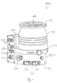
- the turbo molecular pump 111 shown comprises a pump inlet 115 which is surrounded by an inlet flange 113 and to which a recipient (not shown) can be connected in a manner known per se.
- the gas from the recipient can be sucked out of the recipient via the pump inlet 115 and conveyed through the pump to a pump outlet 117 to which a backing pump, such as a rotary vane pump, can be connected.
- the inlet flange 113 forms according to FIG Fig. 1 the upper end of the housing 119 of the vacuum pump 111.
- the housing 119 comprises a lower part 121 on which an electronics housing 123 is arranged laterally. Electrical and / or electronic components of the vacuum pump 111 are accommodated in the electronics housing 123, for example for operating an electric motor 125 arranged in the vacuum pump. A plurality of connections 127 for accessories are provided on the electronics housing 123.
- a data interface 129 for example in accordance with the RS485 standard, and a power supply connection 131 are arranged on the electronics housing 123.
- a flood inlet 133 in particular in the form of a flood valve, is provided on the housing 119 of the turbo molecular pump 111, via which the vacuum pump 111 can be flooded.
- a sealing gas connection 135, which is also referred to as a purge gas connection via which purge gas to protect the electric motor 125 from the gas conveyed by the pump into the engine compartment 137, in which the electric motor 125 in the vacuum pump 111 is housed, can be brought.
- Two coolant connections 139 are also arranged in the lower part 121, one of the coolant connections being provided as an inlet and the other coolant connection being provided as an outlet for coolant, which can be passed into the vacuum pump for cooling purposes.
- the lower side 141 of the vacuum pump can serve as a standing surface, so that the vacuum pump 111 can be operated standing on the lower side 141.
- the vacuum pump 111 can, however, also be attached to a recipient via the inlet flange 113 and can thus be operated in a suspended manner, as it were.
- the vacuum pump 111 can be designed in such a way that it can also be put into operation when it is oriented in a different way than in FIG Fig. 1 is shown.
- Embodiments of the vacuum pump can also be implemented in which the underside 141 cannot be arranged facing downwards, but facing to the side or facing upwards.
- various screws 143 are also arranged by means of which components of the vacuum pump not specified here are attached to one another.
- a bearing cap 145 is attached to the underside 141.
- Fastening bores 147 are also arranged on the underside 141, via which the pump 111 can be fastened to a support surface, for example.
- a coolant line 148 is shown, in which the coolant introduced and discharged via the coolant connections 139 can circulate.
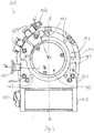
- the vacuum pump comprises several process gas pump stages for conveying the process gas present at the pump inlet 115 to the pump outlet 117.
- a rotor 149 is arranged in the housing 119 and has a rotor shaft 153 rotatable about an axis of rotation 151.
- the turbo-molecular pump 111 comprises several turbo-molecular pump stages connected in series with one another with several radial rotor disks 155 fastened to the rotor shaft 153 and stator disks 157 arranged between the rotor disks 155 and fixed in the housing 119.
- a rotor disk 155 and an adjacent stator disk 157 each form a turbomolecular one Pumping stage.
- the stator disks 157 are held at a desired axial distance from one another by spacer rings 159.
- the vacuum pump also comprises Holweck pump stages which are arranged one inside the other in the radial direction and are connected in series with one another for effective pumping.
- the rotor of the Holweck pump stages comprises a rotor hub 161 arranged on the rotor shaft 153 and two cylinder-jacket-shaped Holweck rotor sleeves 163, 165 which are attached to the rotor hub 161 and carried by the latter, which are oriented coaxially to the axis of rotation 151 and nested in one another in the radial direction.
- two cylinder jacket-shaped Holweck stator sleeves 167, 169 are provided, which are also oriented coaxially to the axis of rotation 151 and, viewed in the radial direction, are nested inside one another.
- the active pumping surfaces of the Holweck pump stages are formed by the jacket surfaces, that is to say by the radial inner and / or outer surfaces, of the Holweck rotor sleeves 163, 165 and the Holweck stator sleeves 167, 169.
- the radial inner surface of the outer Holweck stator sleeve 167 lies opposite the radial outer surface of the outer Holweck rotor sleeve 163 with the formation of a radial Holweck gap 171 and with this forms the first Holweck pump stage following the turbomolecular pumps.
- the radial inner surface of the outer Holweck rotor sleeve 163 faces the radial outer surface of the inner Holweck stator sleeve 169 with the formation of a radial Holweck gap 173 and forms with this a second Holweck pumping stage.
- the radial inner surface of the inner Holweck stator sleeve 169 lies opposite the radial outer surface of the inner Holweck rotor sleeve 165 with the formation of a radial Holweck gap 175 and with this forms the third Holweck pumping stage.
- a radially running channel can be provided, via which the radially outer Holweck gap 171 is connected to the central Holweck gap 173.
- a radially running channel can be provided at the upper end of the inner Holweck stator sleeve 169, via which the middle Holweck gap 173 is connected to the radially inner Holweck gap 175.
- a connecting channel 179 to the outlet 117 can also be provided at the lower end of the radially inner Holweck rotor sleeve 165.
- the aforementioned pump-active surfaces of the Holweck stator sleeves 163, 165 each have a plurality of Holweck grooves running spirally around the axis of rotation 151 in the axial direction, while the opposite lateral surfaces of the Holweck rotor sleeves 163, 165 are smooth and the gas for operating the Drive vacuum pump 111 in the Holweck grooves.
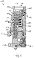
- a roller bearing 181 is provided in the area of the pump outlet 117 and a permanent magnetic bearing 183 in the area of the pump inlet 115.
- a conical injection molded nut 185 is provided on the rotor shaft 153 with an outer diameter that increases towards the roller bearing 181.
- the injection-molded nut 185 is in sliding contact with at least one stripper of an operating medium reservoir.
- the operating medium reservoir comprises several absorbent disks 187 stacked on top of one another, which are impregnated with an operating medium for the roller bearing 181, e.g. with a lubricant.
- the operating medium is transferred by capillary action from the operating medium reservoir via the scraper to the rotating injection nut 185 and, as a result of the centrifugal force, is conveyed along the injection nut 185 in the direction of the increasing outer diameter of the injection nut 92 to the roller bearing 181, where it eg fulfills a lubricating function.
- the roller bearing 181 and the operating medium store are enclosed in the vacuum pump by a trough-shaped insert 189 and the bearing cover 145.
- the permanent magnetic bearing 183 comprises a rotor-side bearing half 191 and a stator-side bearing half 193, each of which comprises a ring stack of several permanent magnetic rings 195, 197 stacked on top of one another in the axial direction.
- the ring magnets 195, 197 are opposite one another with the formation of a radial bearing gap 199, the rotor-side ring magnets 195 being arranged radially on the outside and the stator-side ring magnets 197 being arranged radially on the inside.
- the magnetic field present in the bearing gap 199 causes magnetic repulsive forces between the ring magnets 195, 197, which cause the rotor shaft 153 to be supported radially.
- the rotor-side ring magnets 195 are carried by a carrier section 201 of the rotor shaft 153 which surrounds the ring magnets 195 radially on the outside.
- the stator-side ring magnets 197 are carried by a stator-side carrier section 203 which extends through the ring magnets 197 and is suspended from radial struts 205 of the housing 119.
- the ring magnets 195 on the rotor side are fixed parallel to the axis of rotation 151 by a cover element 207 coupled to the carrier section 203.
- the stator-side ring magnets 197 are fixed parallel to the axis of rotation 151 in one direction by a fastening ring 209 connected to the carrier section 203 and a fastening ring 211 connected to the carrier section 203.
- a plate spring 213 can also be provided between the fastening ring 211 and the ring magnet 197.
- An emergency or backup bearing 215 is provided inside the magnetic bearing, which runs empty during normal operation of the vacuum pump 111 without contact and only comes into engagement with an excessive radial deflection of the rotor 149 relative to the stator in order to provide a radial stop for the rotor 149 form, since a collision of the rotor-side structures with the stator-side structures is prevented.
- the backup bearing 215 is designed as an unlubricated roller bearing and forms a radial gap with the rotor 149 and / or the stator, which has the effect that the backup bearing 215 is disengaged during normal pumping operation.
- the radial deflection at which the backup bearing 215 engages is dimensioned large enough that the backup bearing 215 does not come into engagement during normal operation of the vacuum pump, and at the same time small enough that a collision of the rotor-side structures with the stator-side structures under all circumstances is prevented.
- the vacuum pump 111 comprises the electric motor 125 for rotatingly driving the rotor 149.
- the armature of the electric motor 125 is formed by the rotor 149, the rotor shaft 153 of which extends through the motor stator 217.
- a permanent magnet arrangement can be embedded radially on the outside or embedded in the section of the rotor shaft 153 extending through the motor stator 217 be arranged.
- the motor stator 217 is fixed in the housing within the motor compartment 137 provided for the electric motor 125.
- a sealing gas which is also referred to as a flushing gas and which can be air or nitrogen, for example, can enter the engine compartment 137 via the sealing gas connection 135.
- the electric motor 125 can be protected from process gas, e.g. from corrosive components of the process gas, via the sealing gas.
- the engine compartment 137 can also be evacuated via the pump outlet 117, i.e. the vacuum pressure produced by the backing pump connected to the pump outlet 117 is at least approximately in the engine compartment 137.
- a so-called and known labyrinth seal 223 can also be provided between the rotor hub 161 and a wall 221 delimiting the engine compartment 137, in particular to achieve better sealing of the motor compartment 217 from the Holweck pump stages located radially outside.
- the turbo molecular pump of the Figs. 1 to 5 forms a vacuum pump according to the invention.
- the Fig. 6 shows details which are also used in a turbo molecular pump according to FIGS Figs. 1 to 5 can be provided, even if they are not expressly shown there.
- FIG. 11 shows a schematic block diagram of a turbo molecular pump 111 according to an embodiment of the present invention.
- the one in the Fig. 6 The turbo molecular pump 111 shown has a plurality of pump components 225, a heating device 227 for heating at least one of the pump components 225 and a sensor 229 for detecting a measured variable for the pump operation.
- a sensor 229 for detecting a measured variable for the pump operation.
- several sensors 229 can also be provided, for example one sensor 229 per pump component 225.
- the senor 229 is arranged independently of the heating device 227.
- the sensor 229 is not arranged as part of the heating device 227 or within the heating device 227, but rather at a distance therefrom.
- the sensor 227 can, for example, be arranged in a pump interior, in particular in or on a pump component 225, and can thus be set up to detect a measured variable directly in or on the pump component 225. As a result, the respective measured variable can be recorded in critical areas or adjacent to critical areas of the turbo molecular pump 111.
- the sensor 229 can be designed to detect a measured variable for the control and / or regulation of the pump operation, in particular a pump drive 231.
- the pump drive 231 can correspond to or have the electric motor 125 described above.
- the sensor 229 can furthermore be designed to influence the pump operation, in particular the pump drive 231, via a pump control and / or pump regulating device 233.
- the sensor 229 can be connected to the pump control and / or pump regulating device 233, in particular via a wired or wireless data connection.
- the sensor 229 can in particular be designed as a temperature sensor. Accordingly, the sensor 229 can be set up to detect a pump operating temperature and / or to detect the temperature of the pump component 225, in particular to detect a predefined maximum temperature of the pump component 225.
- the heating device 227 is now configured for operation as a function of the measured variable detected by the sensor 225, in particular a detected temperature.
- the heating operation of the heating device 227 accordingly takes place as a function of sensor data, in particular temperature data, which are detected by the sensor 229.
- the heating device 227 can thus be designed without its own sensors, as a result of which the number of components can be reduced.
- the sensor 229 can be connected directly to the heating device 227, in particular via a data connection.
- the sensor 229 can be indirectly connected to the heating device 227 via the pump control and / or pump regulation device 233.
- the latter applies in particular in the case of the control and / or regulation of the heating device 227 via the pump control and / or pump regulation device 233.
- the data connections can be wired or wireless.
- the heating device 227 can be set up to maintain a minimum temperature and / or maximum temperature and / or to heat up to a minimum temperature and / or maximum temperature.
- This can be a temperature detected by the sensor 229 on the pump component 225, wherein the respective minimum or maximum temperature can be predefined, in particular with regard to the desired operating properties of the turbo-molecular pump 111 and / or with regard to the material and wear properties of the respective Pump component 225.
- the minimum temperature can be selected with regard to a low tendency to condensation and the maximum temperature can be selected with regard to permissible material stress.
- the heating device 227 can also be set up to be activated when falling below a predefined limit temperature and / or to be deactivated when the predefined limit temperature is exceeded. Furthermore, the heating power of the heating device 227 can be adjusted and / or regulated when the temperature falls below or exceeds the limit temperature.
- the predefined limit temperature can be a maximum or minimum temperature. The heating device 227 can thus be set up to be switched on and off completely in pump operation. The heating device 227 can also be controlled by means of pulsed, linearly variable or discrete intermediate values.
- the turbo molecular pump 111 has a pump drive 231.
- the heating device 227 can be configured for operation as a function of the power consumed by the pump drive 231. For example, when the power consumption of the pump drive 231 increases, the heating device 227 can be set up to maintain a deactivated state and / or to reduce the heating output.
- the heating device 227 can be set up to activate the heating mode and / or to increase the heating output. Furthermore, the heating device 227 is set up to remain deactivated in a pump run-up mode and in a vacuum-generating mode. In a vacuum-maintaining operation, the heating device can be activated. The heating power can be activated and / or deactivated and / or changed by the pump control and / or pump regulating device 233 or by a separate unit correspondingly provided in the heating device 227.
- the pump drive 231 has a power supply unit 235.
- the power supply unit 235 can - unlike in Fig. 6 shown - be arranged outside the pump drive 231 and connected to it.
- the heating device 227 is set up to draw power from the power supply unit 235 of the pump drive 231.
- the heating device 227 therefore does not need its own power supply unit, so that the number of components of the turbo molecular pump 111 can be further reduced.
- Further components and / or devices of the vacuum pump can also be set up to draw power from the power supply unit 235 of the pump drive 231, such as the pump control and / or pump regulating device 233.
- all consumers of the turbo molecular pump 111 can be used to draw power from the power supply unit 235 of the pump drive 231 be set up.
- the available power of the power supply unit 235 can be divided at least between the pump drive 231 and the heating device 227.
- the available power of the power supply unit 235 can be completely divided between the respective connected consumers.
- available 100 watts from a power supply unit 235 designed as a power supply unit can essentially be divided between the pump drive 231 and the heating device 227.
- the division can be made depending on the operating status. For example, 90 watts can be required by the pump drive 231 in a pump run-up operation.
- the heater 227 remains deactivated. In an operation that generates a vacuum, for example, a vacuum chamber is pumped empty so that there is a relatively high gas load.
- the pump drive 231 can here, for example, require 50 watts.
- the heating device 227 remains deactivated.
- a vacuum chamber In a vacuum-maintaining operation, a vacuum chamber is already pumped empty, so that there is a relatively low or no gas load.
- the turbo-molecular pump 111 is therefore operated at an operating point with no or only a low gas load, so that the pump drive 231 requires, for example, 20 watts or less.
- the heating device 227 can be operated with 80 watts in order to prevent the pump component 225 from cooling down too much.
Description
Die vorliegende Erfindung betrifft eine Vakuumpumpe, insbesondere eine Turbomolekularpumpe, sowie ein Verfahren zum Betreiben einer Vakuumpumpe.The present invention relates to a vacuum pump, in particular a turbo molecular pump, and a method for operating a vacuum pump.
Im Betrieb von Vakuumpumpen kann es wünschenswert sein, bestimmte Temperaturschwellen zu überschreiten beziehungsweise eine maximal erlaubte Pumpentemperatur aufrechtzuerhalten. Dies gilt beispielsweise im Betrieb von Turbomolekularpumpen für das Erreichen niedriger Enddrücke. Ebenso kann im Betrieb von Vorpumpen durch eine höhere Betriebstemperatur eine höhere Wasserdampfverträglichkeit erreicht werden. Insbesondere kann die Kondensationsneigung hierdurch verringert werden.When operating vacuum pumps, it can be desirable to exceed certain temperature thresholds or to maintain a maximum permissible pump temperature. This applies, for example, to the operation of turbo molecular pumps to achieve low ultimate pressures. Likewise, when backing pumps are in operation, a higher operating temperature can achieve a higher water vapor tolerance. In particular, this can reduce the tendency to condense.
Für das Überschreiten bestimmter Temperaturschwellen beziehungsweise zur Aufrechterhaltung verhältnismäßig hoher Pumpentemperaturen werden üblicherweise gesonderte Heizeinrichtungen vorgesehen. Zum einen wird hierdurch die Anzahl notwendiger Komponenten erhöht, was mit hohem apparativem Aufwand verbunden ist und somit hohe Kosten verursacht. Des Weiteren erlaubt eine gesondert vorgesehene Heizeinrichtung nur eine verhältnismäßig ungenaue Temperierung der fraglichen Pumpenbereiche beziehungsweise Pumpenkomponenten.In order to exceed certain temperature thresholds or to maintain relatively high pump temperatures, separate heating devices are usually provided. On the one hand, this increases the number of necessary components, which is associated with a high outlay in terms of equipment and thus causes high costs. Furthermore, a separately provided heating device allows only a relatively imprecise temperature control of the pump areas or pump components in question.
Aus der
Die
In der
Vor diesem Hintergrund bestand die Aufgabe der vorliegenden Erfindung darin, eine Vakuumpumpe anzugeben, welche die Aufrechterhaltung einer jeweils gewünschten Temperatur mit einer höheren Genauigkeit ermöglicht und gleichzeitig mit verringertem Aufwand herstellbar ist. Ebenso bestand die Aufgabe darin, ein Verfahren zum Betreiben einer Vakuumpumpe anzugeben.Against this background, the object of the present invention was to provide a vacuum pump which enables a particular desired temperature to be maintained with greater accuracy and at the same time can be produced with less effort. The task also consisted of specifying a method for operating a vacuum pump.
In Bezug auf die Vakuumpumpe ist die voranstehende Aufgabe mit den Gegenständen der unabhängigen Ansprüche 1 und 8 und in Bezug auf das Verfahren mit den Gegenständen der Ansprüche 14 und 15 gelöst worden. Vorteilhafte Ausgestaltungen sind in den abhängigen Ansprüchen angegeben und werden nachfolgend erörtert.With regard to the vacuum pump, the above object has been achieved with the subject matter of
Eine erfindungsgemäße Vakuumpumpe kann insbesondere als Vorpumpe konfiguriert und/oder angeordnet sein. Es kann sich bei einer erfindungsgemäßen Vakuumpumpe insbesondere um eine Turbomolekularpumpe handeln.A vacuum pump according to the invention can in particular be configured and / or arranged as a backing pump. A vacuum pump according to the invention can in particular be a turbo-molecular pump.
Nach einem ersten Aspekt der Erfindung weist eine erfindungsgemäße Vakuumpumpe wenigstens eine Pumpenkomponente, eine Heizeinrichtung zum Beheizen der Pumpenkomponente sowie einen Sensor zur Erfassung einer Messgröße für den Pumpenbetrieb auf. Erfindungsgemäß ist der Sensor unabhängig von der Heizeinrichtung angeordnet und die Heizeinrichtung für den Betrieb in Abhängigkeit der durch den Sensor erfassten Messgröße konfiguriert.According to a first aspect of the invention, a vacuum pump according to the invention has at least one pump component, a heating device for heating the pump component and a sensor for detecting a measured variable for the pump operation. According to the invention, the sensor is arranged independently of the heating device and the heating device is configured for operation as a function of the measured variable detected by the sensor.
Bei dem Sensor kann es sich somit um eine Komponente handeln, die unabhängig von der Heizeinrichtung in der Vakuumpumpe vorgesehen ist, insbesondere Messgrößen erfasst, die auch anderweitig verwertet werden. Beispielsweise kann der Sensor eine Messgröße erfassen und anderen Einrichtungen als der erfindungsgemäß vorgesehenen Heizeinrichtung zur Verfügung stellen, insbesondere für Funktionalitäten der Vakuumpumpe, die nicht in unmittelbarem Zusammenhang mit der Heizfunktionalität der Heizeinrichtung stehen.The sensor can thus be a component that is provided in the vacuum pump independently of the heating device, in particular it detects measured variables that are also used in other ways. For example, the sensor can detect a measured variable and make it available to other devices than the heating device provided according to the invention, in particular for functionalities of the vacuum pump that are not directly related to the heating functionality of the heating device.
Auf diese Weise lässt sich einerseits eine Reduzierung der Komponentenzahl erzielen, wodurch der apparative Aufwand und damit auch der Kostenaufwand für eine erfindungsgemäße Vakuumpumpe verringert werden kann. Insbesondere kann durch Nutzung eines ohnehin in der Vakuumpumpe vorgesehenen Sensors, der insbesondere auch zu anderen Zwecken in der Vakuumpumpe vorgesehen ist, die Anordnung weiterer Sensoren in redundanter Weise vermieden werden. Der apparative Aufwand lässt sich hiermit effektiv reduzieren.In this way, on the one hand, a reduction in the number of components can be achieved, as a result of which the outlay on equipment and thus also the outlay on costs for a vacuum pump according to the invention can be reduced. In particular, by using a sensor which is already provided in the vacuum pump and which is in particular also provided for other purposes in the vacuum pump, the arrangement of further sensors in a redundant manner can be avoided. The outlay on equipment can thus be effectively reduced.
Gleichzeitig kann bei einer erfindungsgemäßen Vakuumpumpe die Beheizung der Pumpenkomponente mit erhöhter Genauigkeit erfolgen, da der Betrieb in Abhängigkeit von Messdaten eines unabhängig angeordneten Sensors erfolgt. Durch den unabhängig von der Heizeinrichtung vorgesehenen Sensor kann die jeweils zu ermittelnde Messgröße näher oder unmittelbar an der gewünschten Stelle der Vakuumpumpe beziehungsweise der jeweiligen Pumpenkomponente erfasst werden. Die Heizwirkung der Heizeinrichtung an dem jeweils kritischen Teil der Vakuumpumpe kann somit verzögerungsfrei oder mit nur geringer Verzögerung erfasst werden. In Abhängigkeit davon lässt sich die Heizleistung der Heizeinrichtung präzise anpassen. Die Betriebspräzision der Heizeinrichtung kann hierdurch insgesamt verbessert werden.At the same time, in the case of a vacuum pump according to the invention, the pump component can be heated with increased accuracy, since the operation takes place as a function of measurement data from an independently arranged sensor. With the sensor, which is provided independently of the heating device, the respective measured variable to be determined can be detected more closely or directly at the desired location of the vacuum pump or the respective pump component. The heating effect of the heating device on the critical part of the vacuum pump in each case can thus be recorded without delay or with only a slight delay. The heating output of the heating device can be precisely adjusted as a function of this. The operating precision of the heating device can be improved overall as a result.
Ferner bleibt die Heizeinrichtung in einem Pumpenhochlaufbetrieb deaktiviert. In einem solchen Pumpenhochlaufbetrieb erfolgt typischerweise eine verhältnismäßig hohe Leistungsaufnahme eines Pumpenantriebs, beispielsweise mehr als 80 Watt, insbesondere 90 bis 100 Watt. Da diese aufgenommene Leistung zu einem Großteil als Verlustwärme abgegeben wird, kann eine zusätzliche Beheizung durch die Heizeinrichtung unterbleiben. Die Heizeinrichtung kann in einem deaktivierten Zustand verbleiben.Furthermore, the heating device remains deactivated in a pump run-up mode. In such a pump run-up operation, there is typically a proportional high power consumption of a pump drive, for example more than 80 watts, in particular 90 to 100 watts. Since this absorbed power is largely given off as heat loss, additional heating by the heating device can be omitted. The heating device can remain in a deactivated state.
Zusätzlich bleibt die Heizeinrichtung in einem Vakuum erzeugenden Betrieb deaktiviert. In einem Vakuum erzeugenden Betrieb wird beispielsweise eine Vakuumkammer leergepumpt, so dass eine verhältnismäßig hohe Gaslast vorliegt. Auch in einem solchen Betriebszustand nimmt ein Pumpenantrieb eine verhältnismäßig hohe Leistung auf, beispielsweise mehr als 40 Watt, insbesondere 50 bis 60 Watt. Die entsprechend eingebrachte Verlustwärme kann zum Beheizen einer Pumpenkomponente beziehungsweise zur Aufrechterhaltung einer Pumpenkomponententemperatur ausreichend sein, so dass es keiner weiteren Beheizung durch die Heizeinrichtung bedarf.In addition, the heating device remains deactivated in a vacuum-generating mode. In a vacuum-generating operation, for example, a vacuum chamber is pumped empty so that there is a relatively high gas load. Even in such an operating state, a pump drive consumes a relatively high power, for example more than 40 watts, in particular 50 to 60 watts. The correspondingly introduced heat loss can be sufficient to heat a pump component or to maintain a pump component temperature, so that no further heating by the heating device is required.
Gemäß einer bevorzugten Ausgestaltung der erfindungsgemäßen Vakuumpumpe ist der Sensor zur Erfassung einer Messgröße für die Steuerung und/oder Regelung des Pumpenbetriebes, insbesondere eines Pumpenantriebes, ausgebildet. So besteht beispielsweise die Möglichkeit, dass die durch den Sensor jeweils erfasste Messgröße eine Erhöhung, Beibehaltung oder Verringerung der Pumpenantriebsleistung auslöst. Ebenso kann die jeweils erfasste Messgröße eine Notmaßnahme wie zum Beispiel einen Not-Stopp auslösen.According to a preferred embodiment of the vacuum pump according to the invention, the sensor is designed to detect a measured variable for the control and / or regulation of the pump operation, in particular a pump drive. For example, there is the possibility that the measured variable detected by the sensor in each case triggers an increase, maintenance or decrease in the pump drive power. The measured variable recorded in each case can also trigger an emergency measure such as an emergency stop.
Der Sensor kann ferner zur Erfassung einer Messgröße für die Beeinflussung des Pumpenbetriebs über eine Pumpensteuerungs- und/oder Pumpenregelungseinrichtung ausgebildet sein. Dementsprechend kann die jeweils erfasste Messgröße einer Pumpensteuerungs- und/oder Pumpenregelungseinrichtung zur Verfügung gestellt und diese in Abhängigkeit des jeweiligen Messwerts oder der Messwertentwicklung den gegenwärtigen Pumpenbetrieb anpassen.The sensor can also be designed to detect a measured variable for influencing the pump operation via a pump control and / or pump regulating device. Accordingly, the measured variable recorded in each case can be made available to a pump control and / or pump regulating device and this can be adapted to the current pump operation as a function of the respective measured value or the development of the measured value.
Ebenso besteht die Möglichkeit, dass der Sensor zur Erfassung einer Messgröße ausgebildet ist, die lediglich zu informatorischen Zwecken wiedergegeben wird, so dass beispielsweise eine Bedienperson die aktuellen Messwerte der Messgröße einer Anzeigeeinrichtung entnehmen kann. Je nach Messwert kann somit eine Bedienperson zur Veränderung oder Beibehaltung des Pumpenbetriebs veranlasst werden.There is also the possibility that the sensor is designed to detect a measured variable that is only reproduced for informational purposes, so that, for example, an operator can take the current measured values of the measured variable from a display device. Depending on the measured value, an operator can thus be prompted to change or maintain the pump operation.
Gemäß einer bevorzugten Ausgestaltung ist der Sensor beabstandet von der Heizeinrichtung, insbesondere in einem Pumpeninnenraum, angeordnet. Der konstruktive Gestaltungsspielraum wird hierdurch vergrößert, da die Position der Heizeinrichtung insbesondere unabhängig von der Position des Sensors gewählt werden kann. Der Sensor kann insbesondere zur Erfassung einer Messgröße an einer kritischen Stelle der Vakuumpumpe angeordnet werden, so dass bei der Erfassung der jeweiligen Messgröße eine größtmögliche Präzision erzielt werden kann. Insbesondere kann der Sensor zur Erfassung einer Messgröße an oder in der Pumpenkomponente eingerichtet sein. Bei der fraglichen Pumpenkomponente kann es sich beispielsweise um das Pumpengehäuse, um einen Abschnitt des Pumpengehäuses oder auch um eine innerhalb des Pumpengehäuses angeordnete Komponente handeln.According to a preferred embodiment, the sensor is arranged at a distance from the heating device, in particular in a pump interior. The design freedom is increased as a result, since the position of the heating device can in particular be selected independently of the position of the sensor. In particular, the sensor can be arranged at a critical point of the vacuum pump to detect a measured variable, so that the greatest possible precision can be achieved in the detection of the respective measured variable. In particular, the sensor can be set up to detect a measured variable on or in the pump component. The pump component in question can be, for example, the pump housing, a section of the pump housing or a component arranged within the pump housing.
Demgegenüber kann die Wahl der Position der Heizeinrichtung im Hinblick auf eine einfache Gesamtkonzeption, eine einfache Montierbarkeit und/oder im Hinblick auf eine einfache Austauschbarkeit der Heizeinrichtung gewählt sein. Ebenso kann die Wahl der Position der Heizeinrichtung im Hinblick auf eine günstige Überleitung einer Heizleistung auf die jeweils zu beheizende Pumpenkomponente gewählt sein.In contrast, the choice of the position of the heating device can be chosen with a view to a simple overall conception, simple assembly and / or with regard to simple exchangeability of the heating device. Likewise, the choice of the position of the heating device can be chosen with a view to a favorable transfer of a heating power to the respective pump component to be heated.
Gemäß einer weiter bevorzugten Ausgestaltung ist der Sensor ein Temperatursensor. Bei der zu erfassenden Messgröße kann es sich somit um eine Temperatur handeln, insbesondere um eine Komponententemperatur oder um eine Temperatur des jeweils zu fördernden Mediums. In bevorzugter Weise kann der Sensor zur Erfassung einer Pumpenbetriebstemperatur und/oder zur Erfassung der Temperatur der Pumpenkomponente eingerichtet sein, insbesondere zur Erfassung einer vordefinierten Maximaltemperatur der Pumpenkomponente. Zum einen kann hierdurch ein hohes Maß an Betriebssicherheit gewährleistet werden. Des Weiteren wird hierdurch die Möglichkeit geschaffen, den Pumpenbetrieb im Hinblick auf eine bestimmte Temperatur der Pumpenkomponente auszurichten. Beispielsweise kann zur Einhaltung einer jeweils vordefinierten Temperatur der Pumpenkomponente der Pumpenantrieb entsprechend angesteuert und/oder die Heizeinrichtung entsprechend betrieben werden.According to a further preferred embodiment, the sensor is a temperature sensor. The measured variable to be recorded can therefore be a temperature act, in particular a component temperature or a temperature of the respective medium to be conveyed. In a preferred manner, the sensor can be set up to detect a pump operating temperature and / or to detect the temperature of the pump component, in particular to detect a predefined maximum temperature of the pump component. On the one hand, this ensures a high level of operational safety. Furthermore, this creates the possibility of aligning the pump operation with a specific temperature of the pump component. For example, in order to maintain a respectively predefined temperature of the pump component, the pump drive can be controlled accordingly and / or the heating device can be operated accordingly.
In weiter bevorzugter Ausgestaltung ist die Heizeinrichtung ohne Temperatursensor ausgebildet. Es kann also eine Heizeinrichtung vorgesehen sein, die vollständig ohne Temperatursensor ausgestaltet ist, wodurch die Komponentenanzahl der Vakuumpumpe in besonders vorteilhafter Weise verringert werden kann. Hierdurch können insbesondere auch die Herstellkosten für eine erfindungsgemäße Vakuumpumpe verringert werden.In a further preferred embodiment, the heating device is designed without a temperature sensor. A heating device can therefore be provided which is completely designed without a temperature sensor, whereby the number of components of the vacuum pump can be reduced in a particularly advantageous manner. In this way, in particular, the manufacturing costs for a vacuum pump according to the invention can also be reduced.
Weiter bevorzugt kann die Heizeinrichtung zur Verbindung mit einem externen und/oder separat angeordneten Temperatursensor ausgebildet sein. Eine solche Verbindung kann beispielsweise direkt kabelgebunden oder kabellos oder aber auch mittelbar über eine gesonderte Steuerungs- und/oder Regelungseinrichtung vorgesehen sein. Auf diese Weise kann eine Heizeinrichtung trotz Ausgestaltung ohne Temperatursensor im Betrieb präzise ausgeregelt werden, wodurch die Betriebssicherheit einer erfindungsgemäßen Vakuumpumpe weiter verbessert werden kann.More preferably, the heating device can be designed for connection to an external and / or separately arranged temperature sensor. Such a connection can be provided, for example, directly wired or wirelessly or also indirectly via a separate control and / or regulating device. In this way, despite the design without a temperature sensor, a heating device can be precisely regulated during operation, as a result of which the operational reliability of a vacuum pump according to the invention can be further improved.
Gemäß einer Ausgestaltung der Vakuumpumpe kann die Heizeinrichtung extern angebaut oder in einem Pumpeninnenraum angeordnet sein. Eine externe Anordnung der Heizeinrichtung, beispielsweise an einem Gehäuse der Vakuumpumpe ermöglicht eine handhabungsfreundliche Montage und auch einen handhabungsfreundlichen Austausch der Heizeinrichtung. Durch die Anordnung in einem Pumpeninnenraum kann die Heizleistung in besonders effektiver Weise auf die zu beheizende Pumpenkomponente übertragen werden, und somit unmittelbar in den temperaturkritischen Teil der Vakuumpumpe eingebracht werden.According to one embodiment of the vacuum pump, the heating device can be attached externally or arranged in a pump interior. An external arrangement the heating device, for example on a housing of the vacuum pump, enables easy-to-use assembly and also easy-to-use replacement of the heating device. As a result of the arrangement in a pump interior, the heating power can be transferred in a particularly effective manner to the pump component to be heated, and thus introduced directly into the temperature-critical part of the vacuum pump.
Die Heizeinrichtung kann beispielsweise an einem Pumpengehäuse angeordnet und/oder zur Beheizung des Pumpengehäuses angeordnet sein. Insbesondere kann die Heizeinrichtung unmittelbar das Pumpengehäuse oder einen Abschnitt des Pumpengehäuses beheizen. Durch die Beheizung des Pumpengehäuse oder eines Abschnitts des Pumpengehäuses kann mittelbar zumindest eine weitere innerhalb des Pumpengehäuses angeordnete Komponente beheizt werden. Ebenso ist es möglich, dass die Heizeinrichtung zur unmittelbaren Beheizung einer Pumpenkomponente eingerichtet ist, die innerhalb des Pumpengehäuses oder an diesem angeordnet ist.The heating device can, for example, be arranged on a pump housing and / or be arranged for heating the pump housing. In particular, the heating device can directly heat the pump housing or a section of the pump housing. By heating the pump housing or a section of the pump housing, at least one further component arranged within the pump housing can be indirectly heated. It is also possible that the heating device is set up for the direct heating of a pump component which is arranged within the pump housing or on it.
In weiter bevorzugter Weise kann die Heizeinrichtung zur Aufrechterhaltung einer Mindesttemperatur und/oder Maximaltemperatur eingerichtet sein. Hierdurch kann beispielsweise eine im Pumpenbetrieb durch die Leistungsaufnahme des Pumpenantriebs erreichte Pumpentemperatur beziehungsweise Pumpenkomponententemperatur unabhängig von der weiteren Leistungsaufnahme durch den Pumpenantrieb aufrechterhalten werden. Ebenso ist es möglich, dass die Heizeinrichtung zum Aufheizen bis zu einer Mindesttemperatur und/oder Maximaltemperatur eingerichtet ist. Bei einer solchen Ausgestaltung kann die Vakuumpumpe beziehungsweise die jeweilige Pumpenkomponente vor dem Betrieb konditioniert werden, so dass bereits zu Beginn des jeweiligen Pumpenbetriebs die jeweils gewünschten Temperaturverhältnisse vorliegen. Die Betriebseigenschaften der Vakuumpumpe lassen sich auf diese Weise weiter verbessern.In a further preferred manner, the heating device can be set up to maintain a minimum temperature and / or a maximum temperature. In this way, for example, a pump temperature or pump component temperature reached in pump operation by the power consumption of the pump drive can be maintained independently of the further power consumption by the pump drive. It is also possible for the heating device to be set up for heating up to a minimum temperature and / or a maximum temperature. In such a configuration, the vacuum pump or the respective pump component can be conditioned before operation, so that the respectively desired temperature conditions are already present at the beginning of the respective pump operation. The operating properties of the vacuum pump can be further improved in this way.
Gemäß einer weiteren Ausgestaltung kann die Heizeinrichtung dazu eingerichtet sein, bei Unterschreiten einer vordefinierten Grenztemperatur aktiviert und/oder bei Überschreiten der vordefinierten Grenztemperatur deaktiviert zu werden. Somit kann je nach der durch den Sensor erfassten Grenztemperatur die Heizeinrichtung deaktiviert beziehungsweise aktiviert werden. Die jeweils gewünschte Grenztemperatur kann in der Folge mit verhältnismäßig großer Präzision aufrechterhalten werden.According to a further embodiment, the heating device can be set up to be activated when the temperature falls below a predefined limit temperature and / or to be deactivated when the predefined limit temperature is exceeded. Thus, depending on the limit temperature detected by the sensor, the heating device can be deactivated or activated. The limit temperature desired in each case can subsequently be maintained with relatively great precision.
Ebenso ist es möglich, die Heizleistung bei Unterschreiten oder Überschreiten der Grenztemperatur anzupassen und/oder auszuregeln. Durch eine derartige Ausgestaltung der Heizeinrichtung kann ein vollständiges Abschalten der Heizeinrichtung vermieden und die konstante Beibehaltung der jeweils gewünschten Grenztemperatur sichergestellt werden. Insbesondere können etwaige Temperaturschwankungen um die gewünschte und/oder vordefinierte Grenztemperatur herum auf ein Minimum reduziert werden.It is also possible to adjust and / or regulate the heating output when the temperature falls below or exceeds the limit temperature. Such a configuration of the heating device can avoid a complete shutdown of the heating device and the constant maintenance of the respectively desired limit temperature can be ensured. In particular, any temperature fluctuations around the desired and / or predefined limit temperature can be reduced to a minimum.
Ein zweiter Aspekt der vorliegenden Erfindung betrifft eine Vakuumpumpe, insbesondere eine Turbomolekularpumpe, mit einem Pumpenantrieb und mit einer Heizeinrichtung zum Beheizen zumindest einer Pumpenkomponente, wobei die Heizeinrichtung für den Betrieb in Abhängigkeit einer durch den Pumpenantrieb aufgenommenen Leistung konfiguriert ist.A second aspect of the present invention relates to a vacuum pump, in particular a turbomolecular pump, with a pump drive and with a heating device for heating at least one pump component, the heating device being configured to operate as a function of the power consumed by the pump drive.
Auf diese Weise besteht die Möglichkeit, die einzubringende Heizleistung an den Betriebszustand des Pumpenantriebs anzupassen. Bei hoher Leistungsaufnahme durch den Pumpenantrieb kann eine nur geringe oder keine Heizleistung erbracht werden und bei nur geringer Leistungsaufnahme durch den Pumpenantrieb kann eine entsprechend hohe Heizleistung erbracht werden. Insgesamt kann hierdurch eine verhältnismäßig konstante Wärmeleistung in die Vakuumpumpe beziehungsweise in die zu beheizende Pumpenkomponente eingebracht werden.In this way it is possible to adapt the heating power to be introduced to the operating state of the pump drive. In the case of high power consumption by the pump drive, only a small or no heating output can be provided, and with only low power consumption by the pump drive, a correspondingly high heating output can be provided. Overall, this allows a relatively constant heat output to be introduced into the vacuum pump or into the pump component to be heated.
Im Falle von Turbomolekularpumpen ermöglicht der Betrieb der Heizeinrichtung in Abhängigkeit einer durch den Pumpenantrieb aufgenommenen Leistung einen besonders konstanten Wärmeeintrag. Dies ist darauf zurückzuführen, dass durch Turbomolekularpumpen eine verhältnismäßig geringe Förderleistung erbracht wird und der Großteil der durch den Pumpenantrieb aufgenommenen elektrischen Leistung als Verlustwärme anfällt. Sofern nun die Heizeinrichtung für den Betrieb in Abhängigkeit der durch den Pumpenantrieb aufgenommenen Leistung konfiguriert ist, kann auf diese Weise die durch den Pumpenantrieb entstehende Verlustwärme gezielt durch Heizleistung des Heizelements ergänzt werden, um insgesamt eine konstante Verlust- beziehungsweise Wärmeleistung sicherzustellen. Eine vordefinierte oder gewünschte Betriebstemperatur der Vakuumpumpe beziehungsweise der jeweiligen Pumpenkomponente oder auch einer Mehrzahl von Pumpenkomponenten kann auf diese Weise mit hoher Sicherheit aufrechterhalten werden.In the case of turbo molecular pumps, the operation of the heating device enables a particularly constant heat input as a function of the power consumed by the pump drive. This is due to the fact that turbomolecular pumps provide a relatively low delivery rate and the majority of the electrical power consumed by the pump drive occurs as heat loss. If the heating device is now configured for operation as a function of the power consumed by the pump drive, the heat loss caused by the pump drive can be supplemented in a targeted manner by the heating power of the heating element in order to ensure a constant overall loss or heat power. A predefined or desired operating temperature of the vacuum pump or of the respective pump component or also of a plurality of pump components can in this way be maintained with a high degree of reliability.
Ferner bleibt die Heizeinrichtung der Vakuumpumpe ebenfalls in einem Pumpenhochlaufbetrieb und in einem Vakuum erzeugenden Betrieb deaktiviert.Furthermore, the heating device of the vacuum pump also remains deactivated in a pump run-up mode and in a vacuum-generating mode.
Eine voranstehend beschriebene Vakuumpumpe gemäß dem zweiten Aspekt der Erfindung kann in vorteilhafter Weise zusätzlich gemäß dem ersten Aspekt der Erfindung ausgebildet sein. Dementsprechend kann die Ausgestaltung gemäß dem ersten Aspekt der Erfindung mit der Ausgestaltung gemäß dem zweiten Aspekt der Erfindung kombiniert werden.A vacuum pump described above according to the second aspect of the invention can advantageously also be designed according to the first aspect of the invention. Accordingly, the configuration according to the first aspect of the invention can be combined with the configuration according to the second aspect of the invention.
Es besteht folglich die Möglichkeit, die Heizeinrichtung für den Betrieb in Abhängigkeit einer durch den Pumpenantrieb aufgenommenen Leistung und gleichzeitig in Abhängigkeit einer durch einen unabhängig von der Heizeinrichtung angeordneten Sensor erfassten Messgröße zu konfigurieren. Ausschlaggebend für den Betrieb der Heizeinrichtung kann folglich sowohl die durch den Pumpenantrieb aufgenommene Leistung als auch die durch den Sensor erfasste Messgröße sein. Die Betriebssicherheit und Heizgenauigkeit lässt sich auf diese Weise weiter verbessern.There is consequently the possibility of configuring the heating device for operation as a function of a power consumed by the pump drive and, at the same time, as a function of a measured variable detected by a sensor arranged independently of the heating device. Consequently, both the power consumed by the pump drive and the measured variable detected by the sensor can be decisive for the operation of the heating device. The operational safety and heating accuracy can be further improved in this way.
In bevorzugter Weise ist die Heizeinrichtung für den Betrieb in Abhängigkeit vordefinierter Prozessschritte oder zumindest eines weiteren Sensors konfiguriert. Insbesondere kann es sich bei dem weiteren Sensor um einen zusätzlich zu einem Temperatursensor vorgesehenen Sensor handeln, beispielsweise um einen Drucksensor oder um einen Strömungsgeschwindigkeitssensor. Hierdurch kann die Betriebssicherheit der Vakuumpumpe weiter verbessert werden.The heating device is preferably configured for operation as a function of predefined process steps or at least one further sensor. In particular, the further sensor can be a sensor provided in addition to a temperature sensor, for example a pressure sensor or a flow rate sensor. As a result, the operational reliability of the vacuum pump can be further improved.
Gemäß einer weiter bevorzugten Ausgestaltung der Vakuumpumpe ist die Heizeinrichtung bei Erhöhung der Leistungsaufnahme eines Pumpenantriebs zur Verringerung der Heizleistung und/oder zur Beibehaltung eines deaktivierten Zustands eingerichtet. Auf diese Weise kann der Wärmeeintrag auf die Verlustwärme des Pumpenantriebs begrenzt werden, wodurch die Gefahr einer Überhitzung verringert werden kann.According to a further preferred embodiment of the vacuum pump, when the power consumption of a pump drive increases, the heating device is set up to reduce the heating power and / or to maintain a deactivated state. In this way, the heat input can be limited to the heat loss from the pump drive, which can reduce the risk of overheating.
Gemäß einer weiter bevorzugten Ausgestaltung ist die Heizeinrichtung bei Verringerung der Leistungsaufnahme eines Pumpenantriebs zur Aktivierung des Heizbetriebs und/oder zur Erhöhung der Heizleistung eingerichtet. Die durch den Pumpenantrieb eingebrachte Verlustwärme kann auf diese Weise gezielt durch Wärmeleistung der Heizeinrichtung ergänzt werden, wodurch die Gefahr einer unerwünschten Abkühlung der Vakuumpumpe beziehungsweise der jeweiligen Pumpenkomponente verringert werden kann.According to a further preferred embodiment, when the power consumption of a pump drive is reduced, the heating device is set up to activate the heating mode and / or to increase the heating output. The heat loss introduced by the pump drive can in this way be supplemented in a targeted manner by the heat output of the heating device, whereby the risk of undesired cooling of the vacuum pump or the respective pump component can be reduced.
Schließlich kann die Heizeinrichtung dazu eingerichtet sein, in einem Vakuum erhaltenden Betrieb aktiviert zu werden beziehungsweise die jeweilige Heizleistung zu erhöhen. In einem solchen Vakuum erhaltenden Betrieb ist die jeweilige Vakuumkammer bereits leergepumpt und die Vakuumpumpe kann auf einem Betriebspunkt ohne Gaslast betrieben werden. In einem solchen Betriebszustand ist die durch den Pumpenantrieb aufgenommene Leistung verhältnismäßig gering, so dass auch eine entsprechend geringe Verlustwärme entsteht. Um eine unerwünschte Abkühlung der Pumpenkomponente der Vakuumpumpe zu vermeiden, kann in diesem Betriebszustand eine Aktivierung der Heizeinrichtung beziehungsweise eine Erhöhung der Heizleistung erfolgen. Beispielsweise kann in einem Vakuum erhaltenden Betrieb eine Leistungsaufnahme durch den Pumpenantrieb von lediglich 20 Watt oder weniger erfolgen, so dass eine Heizleistung von etwa 80 Watt erbracht werden kann. Insbesondere kann eine zur Verfügung stehende Gesamtleistung von etwa 100 W aufgeteilt werden in 20 Watt für den Pumpenantrieb und etwa 80 Watt für die Heizeinrichtung.Finally, the heating device can be set up to be activated in a vacuum-maintaining operation or to increase the respective heating output. In such a vacuum-maintaining operation, the respective vacuum chamber is already pumped empty and the vacuum pump can be operated at an operating point without gas load. In such an operating state, the The power consumed by the pump drive is relatively low, so that there is also a correspondingly low heat loss. In order to avoid undesired cooling of the pump component of the vacuum pump, the heating device can be activated or the heating power can be increased in this operating state. For example, in a vacuum-maintaining operation, the pump drive can consume only 20 watts or less of power, so that a heating output of around 80 watts can be provided. In particular, an available total power of about 100 W can be divided into 20 watts for the pump drive and about 80 watts for the heating device.
Es kann weiter von Vorteil sein, wenn ein Pumpenantrieb mit einer Leistungsversorgungseinheit vorgesehen ist und die Heizeinrichtung zum Leistungsbezug von der Leistungsversorgungseinheit des Pumpenantriebs eingerichtet ist. Hierdurch wird eine effizientere Nutzung vorhandener Komponenten ermöglicht, so dass insgesamt die Anzahl erforderlicher Komponenten reduziert werden kann. Insbesondere ist es möglich, die Heizeinrichtung ohne eigene Leistungsversorgungseinrichtung auszubilden, so dass der apparative Aufwand und folglich auch die Kosten insgesamt reduziert werden können. Es besteht ferner die Möglichkeit, auch weitere Einheiten, wie zum Beispiel eine Pumpensteuerungs- und/oder Pumpenregelungseinrichtung für den Leistungsbezug von der Leistungsversorgungseinheit des Pumpenantriebs einzurichten. Ebenso können Ventile und/oder Lüfter für den Leistungsbezug von der Leistungsversorgungseinheit eingerichtet sein.It can also be advantageous if a pump drive with a power supply unit is provided and the heating device is set up to draw power from the power supply unit of the pump drive. This enables a more efficient use of existing components, so that overall the number of required components can be reduced. In particular, it is possible to design the heating device without its own power supply device, so that the outlay on equipment and consequently also the costs can be reduced overall. There is also the possibility of setting up further units, such as a pump control and / or pump regulating device for drawing power from the power supply unit of the pump drive. Likewise, valves and / or fans can be set up for drawing power from the power supply unit.
In weiter bevorzugter Weise kann die verfügbare Leistung der Leistungsversorgungseinheit zumindest zwischen dem Pumpenantrieb und der Heizeinrichtung aufgeteilt werden. In besonders bevorzugter Weise kann die verfügbare Leistung der Leistungsversorgungseinheit vollständig aufgeteilt werden, insbesondere zwischen sämtlichen Verbrauchern, die an die Leistungsversorgungseinheit des Pumpenantriebs angeschlossen sind. Auf diese Weise wird unabhängig von der jeweils durch den Pumpenantrieb aufgenommenen Leistung eine im Wesentlichen konstante Beheizung erzielt. Dies ermöglicht einen insgesamt einfachen und kompakten Aufbau bei einem gleichzeitig hohen Maß an Betriebssicherheit.In a further preferred manner, the available power of the power supply unit can be divided at least between the pump drive and the heating device. In a particularly preferred manner, the available power of the power supply unit can be completely divided, in particular between all consumers that are connected to the power supply unit of the pump drive. This way it becomes independent of the a substantially constant heating achieved in each case by the power consumed by the pump drive. This enables an overall simple and compact structure with a high level of operational reliability at the same time.
Ferner kann in bevorzugter Weise die Pumpensteuerungs- und/oder Pumpenregelungseinrichtung dazu eingerichtet sein, eine Ansteuerung sämtlicher an die Leistungsversorgungseinheit des Pumpenantriebs angeschlossenen Verbraucher in Abhängigkeit eines Pumpenbetriebszustandes, insbesondere einer von dem Pumpenantrieb aufgenommenen elektrischen Leistung, und/oder einer von dem Sensor erfassten Messgröße vorzunehmen. Dies gewährleistet einen insgesamt sicheren und effizienten Pumpenbetrieb.Furthermore, the pump control and / or pump regulating device can preferably be set up to control all consumers connected to the power supply unit of the pump drive as a function of a pump operating state, in particular an electrical power consumed by the pump drive and / or a measured variable detected by the sensor . This ensures an overall safe and efficient pump operation.
Ein weiterer Aspekt der vorliegenden Erfindung betrifft ein Verfahren zum Betreiben einer Vakuumpumpe, insbesondere einer voranstehend beschriebenen Vakuumpumpe, bei dem durch einen Sensor eine Messgröße für den Pumpenbetrieb erfasst wird, und bei dem eine Pumpenkomponente durch eine unabhängig von dem Sensor angeordnete Heizeinrichtung in Abhängigkeit der durch den Sensor erfassten Messgröße beheizt wird.Another aspect of the present invention relates to a method for operating a vacuum pump, in particular a vacuum pump described above, in which a measured variable for the pump operation is detected by a sensor, and in which a pump component is provided by a heating device arranged independently of the sensor as a function of the the measured variable recorded by the sensor is heated.
Ein noch weiterer Aspekt der Erfindung betrifft ein Verfahren zum Betreiben einer Vakuumpumpe, insbesondere einer voranstehend beschriebenen Vakuumpumpe, bei dem ein Pumpenantrieb von einer Leistungsversorgungseinheit Leistung aufnimmt und bei dem eine Heizeinrichtung in Abhängigkeit der durch den Pumpenantrieb aufgenommenen Leistung zumindest eine Pumpenkomponente beheizt.Yet another aspect of the invention relates to a method for operating a vacuum pump, in particular a vacuum pump described above, in which a pump drive consumes power from a power supply unit and in which a heating device heats at least one pump component depending on the power consumed by the pump drive.
Bei beiden vorstehend erwähnten Verfahren bleibt die Heizeinrichtung der Vakuumpumpe in einem Pumpenhochlaufbetrieb und in einem Vakuum erzeugenden Betrieb deaktiviert.In both of the above-mentioned methods, the heating device of the vacuum pump remains deactivated in a pump run-up mode and in a vacuum-generating mode.
In bevorzugter Weise können die voranstehend erwähnten Verfahren zum Betreiben einer Vakuumpumpe miteinander kombiniert werden. Dementsprechend besteht die Möglichkeit, dass eine Pumpenkomponente durch eine unabhängig von dem Sensor angeordnete Heizeinrichtung in Abhängigkeit der durch den Sensor erfassten Messgröße und in Abhängigkeit der durch den Pumpenantrieb aufgenommenen Leistung beheizt wird.In a preferred manner, the above-mentioned methods for operating a vacuum pump can be combined with one another. Accordingly, there is the possibility that a pump component is heated by a heating device arranged independently of the sensor as a function of the measured variable detected by the sensor and as a function of the power consumed by the pump drive.
Die obigen Ausführungen zu der erfindungsgemäßen Vakuumpumpe gemäß dem ersten und/oder dem zweiten Aspekt gelten entsprechend auch für die erfindungsgemäßen Verfahren zum Betreiben einer Vakuumpumpe.The above statements regarding the vacuum pump according to the invention according to the first and / or the second aspect also apply accordingly to the method according to the invention for operating a vacuum pump.
Nachfolgend wird die Erfindung beispielhaft anhand vorteilhafter Ausführungsformen unter Bezugnahme auf die beigefügten Figuren beschrieben. Es zeigen, jeweils schematisch:
- Fig. 1
- eine perspektivische Ansicht einer Turbomolekularpumpe,
- Fig. 2
- eine Ansicht der Unterseite der Turbomolekularpumpe von
Fig. 1 , - Fig. 3
- einen Querschnitt der Turbomolekularpumpe längs der in
Fig. 2 gezeigten Schnittlinie A-A, - Fig. 4
- eine Querschnittsansicht der Turbomolekularpumpe längs der in
Fig. 2 gezeigten Schnittlinie B-B, - Fig. 5
- eine Querschnittsansicht der Turbomolekularpumpe längs der in
Fig. 2 gezeigten Schnittlinie C-C, - Fig. 6
- ein Blockdiagramm einer Turbomolekularpumpe gemäß einer Ausführungsform der Erfindung.
- Fig. 1
- a perspective view of a turbo molecular pump,
- Fig. 2
- a view of the underside of the turbo molecular pump of FIG
Fig. 1 , - Fig. 3
- a cross section of the turbo molecular pump along the in
Fig. 2 shown section line AA, - Fig. 4
- a cross-sectional view of the turbo molecular pump along the line in FIG
Fig. 2 shown section line BB, - Fig. 5
- a cross-sectional view of the turbo molecular pump along the line in FIG
Fig. 2 shown section line CC, - Fig. 6
- a block diagram of a turbo molecular pump according to an embodiment of the invention.
Die in
Der Einlassflansch 113 bildet bei der Ausrichtung der Vakuumpumpe gemäß
Am Gehäuse 119 der Turbomolekularpumpe 111 ist ein Fluteinlass 133, insbesondere in Form eines Flutventils, vorgesehen, über den die Vakuumpumpe 111 geflutet werden kann. Im Bereich des Unterteils 121 ist ferner noch ein Sperrgasanschluss 135, der auch als Spülgasanschluss bezeichnet wird, angeordnet, über welchen Spülgas zum Schutz des Elektromotors 125 vor dem von der Pumpe geförderten Gas in den Motorraum 137, in welchem der Elektromotor 125 in der Vakuumpumpe 111 untergebracht ist, gebracht werden kann. Im Unterteil 121 sind ferner noch zwei Kühlmittelanschlüsse 139 angeordnet, wobei einer der Kühlmittelanschlüsse als Einlass und der andere Kühlmittelanschluss als Auslass für Kühlmittel vorgesehen ist, das zu Kühlzwecken in die Vakuumpumpe geleitet werden kann.A
Die untere Seite 141 der Vakuumpumpe kann als Standfläche dienen, sodass die Vakuumpumpe 111 auf der Unterseite 141 stehend betrieben werden kann. Die Vakuumpumpe 111 kann aber auch über den Einlassflansch 113 an einem Rezipienten befestigt werden und somit gewissermaßen hängend betrieben werden. Außerdem kann die Vakuumpumpe 111 so gestaltet sein, dass sie auch in Betrieb genommen werden kann, wenn sie auf andere Weise ausgerichtet ist als in
An der Unterseite 141, die in
An der Unterseite 141 sind außerdem Befestigungsbohrungen 147 angeordnet, über welche die Pumpe 111 beispielsweise an einer Auflagefläche befestigt werden kann.Fastening bores 147 are also arranged on the
In den
Wie die Schnittdarstellungen der
In dem Gehäuse 119 ist ein Rotor 149 angeordnet, der eine um eine Rotationsachse 151 drehbare Rotorwelle 153 aufweist.A
Die Turbomolekularpumpe 111 umfasst mehrere pumpwirksam miteinander in Serie geschaltete turbomolekulare Pumpstufen mit mehreren an der Rotorwelle 153 befestigten radialen Rotorscheiben 155 und zwischen den Rotorscheiben 155 angeordneten und in dem Gehäuse 119 festgelegten Statorscheiben 157. Dabei bilden eine Rotorscheibe 155 und eine benachbarte Statorscheibe 157 jeweils eine turbomolekulare Pumpstufe. Die Statorscheiben 157 sind durch Abstandsringe 159 in einem gewünschten axialen Abstand zueinander gehalten.The turbo-
Die Vakuumpumpe umfasst außerdem in radialer Richtung ineinander angeordnete und pumpwirksam miteinander in Serie geschaltete Holweck-Pumpstufen. Der Rotor der Holweck-Pumpstufen umfasst eine an der Rotorwelle 153 angeordnete Rotornabe 161 und zwei an der Rotornabe 161 befestigte und von dieser getragene zylindermantelförmige Holweck-Rotorhülsen 163, 165, die koaxial zur Rotationsachse 151 orientiert und in radialer Richtung ineinander geschachtelt sind. Ferner sind zwei zylindermantelförmige Holweck-Statorhülsen 167, 169 vorgesehen, die ebenfalls koaxial zu der Rotationsachse 151 orientiert und in radialer Richtung gesehen ineinander geschachtelt sind.The vacuum pump also comprises Holweck pump stages which are arranged one inside the other in the radial direction and are connected in series with one another for effective pumping. The rotor of the Holweck pump stages comprises a
Die pumpaktiven Oberflächen der Holweck-Pumpstufen sind durch die Mantelflächen, also durch die radialen Innen- und/oder Außenflächen, der Holweck-Rotorhülsen 163, 165 und der Holweck-Statorhülsen 167, 169 gebildet. Die radiale Innenfläche der äußeren Holweck-Statorhülse 167 liegt der radialen Außenfläche der äußeren Holweck-Rotorhülse 163 unter Ausbildung eines radialen Holweck-Spalts 171 gegenüber und bildet mit dieser die der Turbomolekularpumpen nachfolgende erste Holweck-Pumpstufe. Die radiale Innenfläche der äußeren Holweck-Rotorhülse 163 steht der radialen Außenfläche der inneren Holweck-Statorhülse 169 unter Ausbildung eines radialen Holweck-Spalts 173 gegenüber und bildet mit dieser eine zweite Holweck-Pumpstufe. Die radiale Innenfläche der inneren Holweck-Statorhülse 169 liegt der radialen Außenfläche der inneren Holweck-Rotorhülse 165 unter Ausbildung eines radialen Holweck-Spalts 175 gegenüber und bildet mit dieser die dritte Holweck-Pumpstufe.The active pumping surfaces of the Holweck pump stages are formed by the jacket surfaces, that is to say by the radial inner and / or outer surfaces, of the
Am unteren Ende der Holweck-Rotorhülse 163 kann ein radial verlaufender Kanal vorgesehen sein, über den der radial außenliegende Holweck-Spalt 171 mit dem mittleren Holweck-Spalt 173 verbunden ist. Außerdem kann am oberen Ende der inneren Holweck-Statorhülse 169 ein radial verlaufender Kanal vorgesehen sein, über den der mittlere Holweck-Spalt 173 mit dem radial innenliegenden Holweck-Spalt 175 verbunden ist. Dadurch werden die ineinander geschachtelten Holweck-Pumpstufen in Serie miteinander geschaltet. Am unteren Ende der radial innenliegenden Holweck-Rotorhülse 165 kann ferner ein Verbindungskanal 179 zum Auslass 117 vorgesehen sein.At the lower end of the
Die vorstehend genannten pumpaktiven Oberflächen der Holweck-Statorhülsen 163, 165 weisen jeweils mehrere spiralförmig um die Rotationsachse 151 herum in axialer Richtung verlaufende Holweck-Nuten auf, während die gegenüberliegenden Mantelflächen der Holweck-Rotorhülsen 163, 165 glatt ausgebildet sind und das Gas zum Betrieb der Vakuumpumpe 111 in den Holweck-Nuten vorantreiben. Zur drehbaren Lagerung der Rotorwelle 153 sind ein Wälzlager 181 im Bereich des Pumpenauslasses 117 und ein Permanentmagnetlager 183 im Bereich des Pumpeneinlasses 115 vorgesehen.The aforementioned pump-active surfaces of the
Im Bereich des Wälzlagers 181 ist an der Rotorwelle 153 eine konische Spritzmutter 185 mit einem zu dem Wälzlager 181 hin zunehmenden Außendurchmesser vorgesehen. Die Spritzmutter 185 steht mit mindestens einem Abstreifer eines Betriebsmittelspeichers in gleitendem Kontakt. Der Betriebsmittelspeicher umfasst mehrere aufeinander gestapelte saugfähige Scheiben 187, die mit einem Betriebsmittel für das Wälzlager 181, z.B. mit einem Schmiermittel, getränkt sind.In the area of the
Im Betrieb der Vakuumpumpe 111 wird das Betriebsmittel durch kapillare Wirkung von dem Betriebsmittelspeicher über den Abstreifer auf die rotierende Spritzmutter 185 übertragen und in Folge der Zentrifugalkraft entlang der Spritzmutter 185 in Richtung des größer werdenden Außendurchmessers der Spritzmutter 92 zu dem Wälzlager 181 hin gefördert, wo es z.B. eine schmierende Funktion erfüllt. Das Wälzlager 181 und der Betriebsmittelspeicher sind durch einen wannenförmigen Einsatz 189 und den Lagerdeckel 145 in der Vakuumpumpe eingefasst.During operation of the
Das Permanentmagnetlager 183 umfasst eine rotorseitige Lagerhälfte 191 und eine statorseitige Lagerhälfte 193, welche jeweils einen Ringstapel aus mehreren in axialer Richtung aufeinander gestapelten permanentmagnetischen Ringen 195, 197 umfassen. Die Ringmagnete 195, 197 liegen einander unter Ausbildung eines radialen Lagerspalts 199 gegenüber, wobei die rotorseitigen Ringmagnete 195 radial außen und die statorseitigen Ringmagnete 197 radial innen angeordnet sind. Das in dem Lagerspalt 199 vorhandene magnetische Feld ruft magnetische Abstoßungskräfte zwischen den Ringmagneten 195, 197 hervor, welche eine radiale Lagerung der Rotorwelle 153 bewirken. Die rotorseitigen Ringmagnete 195 sind von einem Trägerabschnitt 201 der Rotorwelle 153 getragen, welcher die Ringmagnete 195 radial außenseitig umgibt. Die statorseitigen Ringmagnete 197 sind von einem statorseitigen Trägerabschnitt 203 getragen, welcher sich durch die Ringmagnete 197 hindurch erstreckt und an radialen Streben 205 des Gehäuses 119 aufgehängt ist. Parallel zu der Rotationsachse 151 sind die rotorseitigen Ringmagnete 195 durch ein mit dem Trägerabschnitt 203 gekoppeltes Deckelelement 207 festgelegt. Die statorseitigen Ringmagnete 197 sind parallel zu der Rotationsachse 151 in der einen Richtung durch einen mit dem Trägerabschnitt 203 verbundenen Befestigungsring 209 sowie einen mit dem Trägerabschnitt 203 verbundenen Befestigungsring 211 festgelegt. Zwischen dem Befestigungsring 211 und den Ringmagneten 197 kann außerdem eine Tellerfeder 213 vorgesehen sein.The permanent
Innerhalb des Magnetlagers ist ein Not- beziehungsweise Fanglager 215 vorgesehen, welches im normalen Betrieb der Vakuumpumpe 111 ohne Berührung leer läuft und erst bei einer übermäßigen radialen Auslenkung des Rotors 149 relativ zu dem Stator in Eingriff gelangt, um einen radialen Anschlag für den Rotor 149 zu bilden, da eine Kollision der rotorseitigen Strukturen mit den statorseitigen Strukturen verhindert wird. Das Fanglager 215 ist als ungeschmiertes Wälzlager ausgebildet und bildet mit dem Rotor 149 und/oder dem Stator einen radialen Spalt, welcher bewirkt, dass das Fanglager 215 im normalen Pumpbetrieb außer Eingriff ist. Die radiale Auslenkung, bei der das Fanglager 215 in Eingriff gelangt, ist groß genug bemessen, sodass das Fanglager 215 im normalen Betrieb der Vakuumpumpe nicht in Eingriff gelangt, und gleichzeitig klein genug, sodass eine Kollision der rotorseitigen Strukturen mit den statorseitigen Strukturen unter allen Umständen verhindert wird.An emergency or backup bearing 215 is provided inside the magnetic bearing, which runs empty during normal operation of the
Die Vakuumpumpe 111 umfasst den Elektromotor 125 zum drehenden Antreiben des Rotors 149. Der Anker des Elektromotors 125 ist durch den Rotor 149 gebildet, dessen Rotorwelle 153 sich durch den Motorstator 217 hindurch erstreckt. Auf den sich durch den Motorstator 217 hindurch erstreckenden Abschnitt der Rotorwelle 153 kann radial außenseitig oder eingebettet eine Permanentmagnetanordnung angeordnet sein. Zwischen dem Motorstator 217 und dem sich durch den Motorstator 217 hindurch erstreckenden Abschnitt des Rotors 149 ist ein Zwischenraum 219 angeordnet, welcher einen radialen Motorspalt umfasst, über den sich der Motorstator 217 und die Permanentmagnetanordnung zur Übertragung des Antriebsmoments magnetisch beeinflussen können.The
Der Motorstator 217 ist in dem Gehäuse innerhalb des für den Elektromotor 125 vorgesehenen Motorraums 137 festgelegt. Über den Sperrgasanschluss 135 kann ein Sperrgas, das auch als Spülgas bezeichnet wird, und bei dem es sich beispielsweise um Luft oder um Stickstoff handeln kann, in den Motorraum 137 gelangen. Über das Sperrgas kann der Elektromotor 125 vor Prozessgas, z.B. vor korrosiv wirkenden Anteilen des Prozessgases, geschützt werden. Der Motorraum 137 kann auch über den Pumpenauslass 117 evakuiert werden, d.h. im Motorraum 137 herrscht zumindest annäherungsweise der von der am Pumpenauslass 117 angeschlossenen Vorvakuumpumpe bewirkte Vakuumdruck.The
Zwischen der Rotornabe 161 und einer den Motorraum 137 begrenzenden Wandung 221 kann außerdem eine sog. und an sich bekannte Labyrinthdichtung 223 vorgesehen sein, insbesondere um eine bessere Abdichtung des Motorraums 217 gegenüber den radial außerhalb liegenden Holweck-Pumpstufen zu erreichen.A so-called and known
Die Turbomolekularpumpe der
Der Sensor 229 ist erfindungsgemäß unabhängig von der Heizeinrichtung 227 angeordnet. Insbesondere ist der Sensor 229 nicht als Teil der Heizeinrichtung 227 oder innerhalb der Heizeinrichtung 227 sondern beabstandet von dieser angeordnet. Der Sensor 227 kann beispielsweise in einem Pumpeninnenraum, insbesondere in oder an einer Pumpenkomponente 225 angeordnet und somit zur Erfassung einer Messgröße unmittelbar in oder an der Pumpenkomponente 225 eingerichtet sein. Hierdurch kann die jeweilige Messgröße in kritischen Bereichen oder angrenzend an kritische Bereiche der Turbomolekularpumpe 111 erfasst werden.According to the invention, the
Der Sensor 229 kann zur Erfassung einer Messgröße für die Steuerung und/oder Regelung des Pumpenbetriebs, insbesondere eines Pumpenantriebs 231, ausgebildet sein. Dabei kann der Pumpenantrieb 231 dem voranstehend beschriebenen Elektromotor 125 entsprechen oder diesen aufweisen. Der Sensor 229 kann ferner zur Beeinflussung des Pumpenbetriebs, insbesondere des Pumpenantriebs 231, über eine Pumpensteuerungs- und/oder Pumpenregelungseinrichtung 233 ausgebildet sein. Hierzu kann der Sensor 229 mit der Pumpensteuerungs- und/oder Pumpenregelungseinrichtung 233 in Verbindung stehen, insbesondere über eine drahtgebundene oder drahtlose Datenverbindung.The
Der Sensor 229 kann insbesondere als Temperatursensor ausgebildet sein. Dementsprechend kann der Sensor 229 zur Erfassung einer Pumpenbetriebstemperatur und/oder zur Erfassung der Temperatur der Pumpenkomponente 225 eingerichtet sein, insbesondere zur Erfassung einer vordefinierten Maximaltemperatur der Pumpenkomponente 225.The
Erfindungsgemäß ist nun die Heizeinrichtung 227 für den Betrieb in Abhängigkeit der durch den Sensor 225 erfassten Messgröße konfiguriert, insbesondere einer erfassten Temperatur. Der Heizbetrieb der Heizeinrichtung 227 erfolgt demnach in Abhängigkeit von Sensordaten, insbesondere Temperaturdaten, die durch den Sensor 229 erfasst werden. Die Heizeinrichtung 227 kann somit ohne eigene Sensoren ausgebildet sein, wodurch die Komponentenzahl verringert werden kann.According to the invention, the
Gleichzeitig ermöglicht dies eine erhöhte Genauigkeit der Beheizung, da diese in Abhängigkeit von Sensordaten aus kritischen Bereichen der Vakuumpumpe 111 erfolgt. Hierzu kann der Sensor 229 unmittelbar mit der Heizeinrichtung 227 verbunden sein, insbesondere über eine Datenverbindung. Ebenso kann der Sensor 229 mittelbar über die Pumpensteuerungs- und/oder Pumpenregelungseinrichtung 233 mit der Heizeinrichtung 227 verbunden sein. Letzteres gilt insbesondere im Fall der Steuerung und/oder Regelung der Heizeinrichtung 227 über die Pumpensteuerungs- und/oder Pumpenregelungseinrichtung 233. Die Datenverbindungen können drahtgebunden oder drahtlos sein.At the same time, this enables an increased accuracy of the heating, since this takes place as a function of sensor data from critical areas of the
Die Heizeinrichtung 227 kann zur Aufrechterhaltung einer Mindesttemperatur und/oder Maximaltemperatur und/oder zum Aufheizen bis zu einer Mindesttemperatur und/oder Maximaltemperatur eingerichtet sein. Es kann sich dabei um eine durch den Sensor 229 an der Pumpenkomponente 225 erfassten Temperatur handeln, wobei die jeweilige Mindesttemperatur oder Maximaltemperatur vordefiniert sein kann, insbesondere im Hinblick auf die gewünschten Betriebseigenschaften der Turbomolekularpumpe 111 und/oder im Hinblick auf Material- und Verschleißeigenschaften der jeweiligen Pumpenkomponente 225. Beispielsweise kann die Mindesttemperatur hinsichtlich geringer Kondensationsneigung und die Maximaltemperatur kann im Hinblick auf zulässige Materialbeanspruchung gewählt sein.The
Die Heizeinrichtung 227 kann ferner dazu eingerichtet sein, bei Unterschreiten einer vordefinierten Grenztemperatur aktiviert und/oder bei Überschreiten der vordefinierten Grenztemperatur deaktiviert zu werden. Ferner kann die Heizleistung der Heizeinrichtung 227 bei Unterschreiten oder Überschreiten der Grenztemperatur angepasst und/oder ausgeregelt werden. Bei der vordefinierten Grenztemperatur kann es sich um eine Maximal- oder Minimaltemperatur handeln. Die Heizeinrichtung 227 kann also dazu eingerichtet sein, im Pumpenbetrieb vollständig ansowie ausgeschaltet zu werden. Ebenso kann eine Ansteuerung der Heizeinrichtung 227 mittels gepulster, linear veränderlicher oder mittels diskreter Zwischenwerte erfolgen.The
Wie voranstehend bereits erwähnt, weist die Turbomolekularpumpe 111 einen Pumpenantrieb 231 auf. Dabei kann die Heizeinrichtung 227 für den Betrieb in Abhängigkeit einer durch den Pumpenantrieb 231 aufgenommenen Leistung konfiguriert sein. Beispielsweise kann die Heizeinrichtung 227 bei Erhöhung der Leistungsaufnahme des Pumpenantriebs 231 zur Beibehaltung eines deaktivierten Zustands und/oder zur Verringerung der Heizleistung eingerichtet sein.As already mentioned above, the turbo
Ebenso kann die Heizeinrichtung 227 bei Verringerung der Leistungsaufnahme des Pumpenantriebs 231 zur Aktivierung des Heizbetriebs und/oder zur Erhöhung der Heizleistung eingerichtet sein. Ferner ist die Heizeinrichtung 227 dazu eingerichtet, in einem Pumpenhochlaufbetrieb und in einem Vakuum erzeugenden Betrieb deaktiviert zu bleiben. In einem Vakuum erhaltenden Betrieb kann die Heizeinrichtung aktiviert werden. Eine Aktivierung und/oder Deaktivierung und/oder Veränderung der Heizleistung kann durch die Pumpensteuerungs- und/oder Pumpenregelungseinrichtung 233 vorgenommen werden oder durch eine eigene entsprechend in der Heizeinrichtung 227 vorgesehene Einheit.Likewise, when the power consumption of the
Wie der
Im Betrieb der Turbomolekularpumpe 111 kann die verfügbare Leistung der Leistungsversorgungseinheit 235, beispielsweise 100 Watt, zumindest zwischen dem Pumpenantrieb 231 und der Heizeinrichtung 227 aufgeteilt werden. In besonders vorteilhafter Weise kann die verfügbare Leistung der Leistungsversorgungseinheit 235 vollständig auf die jeweils angeschlossenen Verbraucher aufgeteilt werden. Rein beispielhaft können verfügbare 100 Watt aus einer als Netzteil ausgebildeten Leistungsversorgungseinheit 235 im Wesentlichen zischen dem Pumpenantrieb 231 und der Heizeinrichtung 227 aufgeteilt werden. Die Aufteilung kann abhängig vom Betriebszustand erfolgen. Beispielsweise kann in einem Pumpenhochlaufbetrieb 90 Watt durch den Pumpenantrieb 231 benötigt werden. Die Heizeinrichtung 227 bleibt deaktiviert. In einem Vakuum erzeugenden Betrieb wird beispielsweise eine Vakuumkammer leer gepumpt, sodass eine verhältnismäßig hohe Gaslast vorliegt. Der Pumpenantrieb 231 kann hier beispielsweise 50 Watt benötigen. Die Heizeinrichtung 227 bleibt weiterhin deaktiviert.When the turbo
In einem Vakuum erhaltenden Betrieb ist eine Vakuumkammer bereits leer gepumpt, sodass eine verhältnismäßig geringe oder keine Gaslast vorliegt. Die Turbomolekularpumpe 111 wird also auf einen Betriebspunkt ohne oder mit nur geringer Gaslast betrieben, sodass der Pumpenantrieb 231 beispielsweise 20 Watt oder weniger benötigt. Die Heizeinrichtung 227 kann in diesem Zustand mit 80 Watt betrieben werden, um eine zu starke Abkühlung der Pumpenkomponente 225 zu verhindern.In a vacuum-maintaining operation, a vacuum chamber is already pumped empty, so that there is a relatively low or no gas load. The turbo-
Die in den
- 111111
- TurbomolekularpumpeTurbo molecular pump
- 113113
- EinlassflanschInlet flange
- 115115
- PumpeneinlassPump inlet
- 117117
- PumpenauslassPump outlet
- 119119
- Gehäusecasing
- 121121
- UnterteilLower part
- 123123
- ElektronikgehäuseElectronics housing
- 125125
- ElektromotorElectric motor
- 127127
- ZubehöranschlussAccessory connection
- 129129
- DatenschnittstelleData interface
- 131131
- StromversorgungsanschlussPower supply connection
- 133133
- FluteinlassFlood inlet
- 135135
- SperrgasanschlussSealing gas connection
- 137137
- MotorraumEngine compartment
- 139139
- KühlmittelanschlussCoolant connection
- 141141
- Unterseitebottom
- 143143
- Schraubescrew
- 145145
- LagerdeckelBearing cap
- 147147
- BefestigungsbohrungMounting hole
- 148148
- KühlmittelleitungCoolant line
- 149149
- Rotorrotor
- 151151
- RotationsachseAxis of rotation
- 153153
- RotorwelleRotor shaft
- 155155
- RotorscheibeRotor disk
- 157157
- StatorscheibeStator disc
- 159159
- AbstandsringSpacer ring
- 161161
- RotornabeRotor hub
- 163163
- Holweck-RotorhülseHolweck rotor sleeve
- 165165
- Holweck-RotorhülseHolweck rotor sleeve
- 167167
- Holweck-StatorhülseHolweck stator sleeve
- 169169
- Holweck-StatorhülseHolweck stator sleeve
- 171171
- Holweck-SpaltHolweck gap
- 173173
- Holweck-SpaltHolweck gap
- 175175
- Holweck-SpaltHolweck gap
- 179179
- VerbindungskanalConnection channel
- 181181
- Wälzlagerroller bearing
- 183183
- PermanentmagnetlagerPermanent magnet bearings
- 185185
- SpritzmutterInjection nut
- 187187
- Scheibedisc
- 189189
- Einsatzmission
- 191191
- rotorseitige Lagerhälftebearing half on the rotor side
- 193193
- statorseitige Lagerhälftestator-side bearing half
- 195195
- RingmagnetRing magnet
- 197197
- RingmagnetRing magnet
- 199199
- LagerspaltBearing gap
- 201201
- TrägerabschnittBeam section
- 203203
- TrägerabschnittBeam section
- 205205
- radiale Streberadial strut
- 207207
- DeckelelementCover element
- 209209
- StützringSupport ring
- 211211
- BefestigungsringFastening ring
- 213213
- TellerfederDisc spring
- 215215
- Not- bzw. FanglagerEmergency or fishing camp
- 217217
- MotorstatorMotor stator
- 219219
- ZwischenraumSpace
- 221221
- WandungWall
- 223223
- LabyrinthdichtungLabyrinth seal
- 225225
- PumpenkomponentePump component
- 227227
- HeizeinrichtungHeating device
- 229229
- Sensorsensor
- 231231
- PumpenantriebPump drive
- 233233
- Pumpensteuerungs- und/oder PumpenregelungseinrichtungPump control and / or pump regulating device
- 235235
- LeistungsversorgungseinrichtungPower supply facility
Claims (15)
- A vacuum pump, in particular a turbomolecular pump (111), comprising at least one pump component (225); a heating device (227) for heating the pump component (225); and a sensor (229) for detecting a measurement variable for the pump operation, wherein the sensor (229) is arranged independently of the heating device (227) and the heating device (227) is configured for operation in dependence on the measurement variable detected by the sensor (229),
characterized in that
the heating device (227) is configured to remain deactivated in a pump run-up operation and in a vacuum generating operation. - A vacuum pump in accordance with claim 1,
characterized in that
the sensor (229) is configured to detect a measurement variable for the control and/or regulation of the pump operation, in particular of a pump drive (231), and/or to influence the pump operation via a pump control device and/or pump regulation device (233). - A vacuum pump in accordance with claim 1 or claim 2,
characterized in that
the sensor (229) is arranged spaced apart from the heating device (227), in particular in an inner space of the pump, and/or in that the sensor (229) is configured to detect a measurement variable at or in the pump component (225). - A vacuum pump in accordance with at least one of the preceding claims,
characterized in that
the sensor (229) is a temperature sensor and/or is configured to detect a pump operating temperature and/or to detect the temperature of the pump component (225), in particular to detect a predefined maximum temperature of the pump component (225). - A vacuum pump in accordance with at least one of the preceding claims,
characterized in that
the heating device (227) is configured without a temperature sensor and/or for connection to an external and/or separately arranged temperature sensor (229); and/or that the heating device (227) is externally installed or arranged in an inner space of the pump. - A vacuum pump in accordance with at least one of the preceding claims,
characterized in that
the heating device (227) is configured to maintain a minimum temperature and/or a maximum temperature and/or to heat up to a minimum temperature and/or maximum temperature. - A vacuum pump in accordance with at least one of the preceding claims,
characterized in that
the heating device (227) is configured to be activated on a falling below of a predefined limit temperature and/or on an exceeding of the predefined limit temperature and/or to adjust and/or regulate the heating power on a falling below or an exceeding of the limit temperature. - A vacuum pump, in particular in accordance with any one of the preceding claims, comprising a pump drive (231) and a heating device (227) for heating at least one pump component (225), wherein the heating device (227) is configured for operation in dependence on a power absorbed by the pump drive (231),
characterized in that
the heating device (227) is configured to remain deactivated in a pump run-up operation and in a vacuum generating operation. - A vacuum pump in accordance with at least one of the preceding claims,
characterized in that
the heating device (227) is configured to maintain a deactivated state and/or to reduce the heating power on an increase of the power consumption of a pump drive (231). - A vacuum pump in accordance with at least one of the preceding claims,
characterized in that
the heating device (227) is configured to activate the heating operation and/or to increase the heating power on a reduction of the power consumption of a pump drive (231). - A vacuum pump in accordance with at least one of the preceding claims,
characterized in that
the heating device (227) is configured to be activated in a vacuum maintaining mode. - A vacuum pump in accordance with at least one of the preceding claims,
characterized in that
a pump drive (231) is provided with a power supply unit (235) and the heating device (227) is configured to draw power from the power supply unit (235) of the pump drive. - A vacuum pump in accordance with claim 12,
characterized in that
the available electrical power of the power supply unit (235) is at least divided, in particular completely divided, between the pump drive (231) and the heating device (227). - A method of operating a vacuum system, in particular in accordance with at least one of the preceding claims,- in which a measurement variable for the pump operation is detected by a sensor (229), and- in which a pump component (225) is heated by a heating device (227), which is arranged independently of the sensor, in dependence on the measurement variable detected by the sensor (229),characterized in that
the heating device (227) remains deactivated in a pump run-up operation and in a vacuum generating operation. - A method of operating a vacuum pump, in particular in accordance with any one of the preceding claims 1 to 13 and/or a method in accordance with claim 14,- in which a pump drive (231) draws electrical power from a power supply unit (235), and- in which a heating device (227) heats at least one pump component (225) in dependence on the power absorbed by the pump drive (231),characterized in that
the heating device (227) remains deactivated in a pump run-up operation and in a vacuum generating operation.
Priority Applications (2)
| Application Number | Priority Date | Filing Date | Title |
|---|---|---|---|
| EP18167557.0A EP3557071B1 (en) | 2018-04-16 | 2018-04-16 | Vacuum pump and method for operating the same |
| JP2019041548A JP2019183831A (en) | 2018-04-16 | 2019-03-07 | Vacuum pump and method for operating the same |
Applications Claiming Priority (1)
| Application Number | Priority Date | Filing Date | Title |
|---|---|---|---|
| EP18167557.0A EP3557071B1 (en) | 2018-04-16 | 2018-04-16 | Vacuum pump and method for operating the same |
Publications (2)
| Publication Number | Publication Date |
|---|---|
| EP3557071A1 EP3557071A1 (en) | 2019-10-23 |
| EP3557071B1 true EP3557071B1 (en) | 2021-09-22 |
Family
ID=62002562
Family Applications (1)
| Application Number | Title | Priority Date | Filing Date |
|---|---|---|---|
| EP18167557.0A Active EP3557071B1 (en) | 2018-04-16 | 2018-04-16 | Vacuum pump and method for operating the same |
Country Status (2)
| Country | Link |
|---|---|
| EP (1) | EP3557071B1 (en) |
| JP (1) | JP2019183831A (en) |
Family Cites Families (6)
| Publication number | Priority date | Publication date | Assignee | Title |
|---|---|---|---|---|
| JP3557608B2 (en) * | 1996-05-30 | 2004-08-25 | 株式会社島津製作所 | Turbo molecular pump power supply |
| JP2002048088A (en) * | 2000-07-31 | 2002-02-15 | Seiko Instruments Inc | Vacuum pump |
| JP2003172292A (en) * | 2001-12-04 | 2003-06-20 | Shimadzu Corp | Power source device for driving turbo-molecular pump |
| JP5782378B2 (en) * | 2009-08-21 | 2015-09-24 | エドワーズ株式会社 | Vacuum pump |
| JP2013079602A (en) * | 2011-10-04 | 2013-05-02 | Shimadzu Corp | Turbo-molecular pump |
| JP6287475B2 (en) * | 2014-03-28 | 2018-03-07 | 株式会社島津製作所 | Vacuum pump |
-
2018
- 2018-04-16 EP EP18167557.0A patent/EP3557071B1/en active Active
-
2019
- 2019-03-07 JP JP2019041548A patent/JP2019183831A/en active Pending
Also Published As
| Publication number | Publication date |
|---|---|
| EP3557071A1 (en) | 2019-10-23 |
| JP2019183831A (en) | 2019-10-24 |
Similar Documents
| Publication | Publication Date | Title |
|---|---|---|
| EP0646220B1 (en) | Gas friction vacuum pump | |
| EP2826999B1 (en) | Vacuum pump | |
| EP3657021B1 (en) | Vacuum pump | |
| EP3660317B1 (en) | Vacuum device | |
| EP3557071B1 (en) | Vacuum pump and method for operating the same | |
| EP3112687B1 (en) | Detection of the circulation of a flow of auxiliary gas that is supplied to a vacuum pump | |
| EP4212730A1 (en) | Vacuum pump with optimized holweck pump stage to compensate for temperature-related loss of performance | |
| EP3444478A1 (en) | Vacuum pump | |
| EP3438460B1 (en) | Vacuum pump | |
| EP3653885B1 (en) | Method for detecting status information in a vacuum device | |
| EP4108932A1 (en) | Recipient and high vacuum pump | |
| EP3628873B1 (en) | Rotor bearing | |
| EP3683449B1 (en) | Magnetic bearing and vacuum apparatus | |
| EP3611383B1 (en) | Speed control of a rotor of a vacuum pump | |
| EP3536966B1 (en) | Vacuum device | |
| EP2927501B1 (en) | Method and system for determining and evaluating the installation orientation of a device | |
| EP3650702B1 (en) | Use of a synthetic oil in a vacuum pump and vacuum pump | |
| EP3473858B1 (en) | Method for optimizing the life cycle of roller bearings of a vacuum pump | |
| EP3926174B1 (en) | Vacuum pump | |
| EP2927500A1 (en) | System and method for supplying a bearing assembly | |
| EP3034882A2 (en) | Vacuum pump | |
| EP3683447A1 (en) | Vacuum pump | |
| EP3327293B1 (en) | Vacuum pump having multiple inlets | |
| EP3628883B1 (en) | Vacuum pump | |
| EP3633204B1 (en) | Vacuum pump |
Legal Events
| Date | Code | Title | Description |
|---|---|---|---|
| PUAI | Public reference made under article 153(3) epc to a published international application that has entered the european phase |
Free format text: ORIGINAL CODE: 0009012 |
|
| STAA | Information on the status of an ep patent application or granted ep patent |
Free format text: STATUS: THE APPLICATION HAS BEEN PUBLISHED |
|
| AK | Designated contracting states |
Kind code of ref document: A1 Designated state(s): AL AT BE BG CH CY CZ DE DK EE ES FI FR GB GR HR HU IE IS IT LI LT LU LV MC MK MT NL NO PL PT RO RS SE SI SK SM TR |
|
| AX | Request for extension of the european patent |
Extension state: BA ME |
|
| STAA | Information on the status of an ep patent application or granted ep patent |
Free format text: STATUS: REQUEST FOR EXAMINATION WAS MADE |
|
| 17P | Request for examination filed |
Effective date: 20200416 |
|
| RBV | Designated contracting states (corrected) |
Designated state(s): AL AT BE BG CH CY CZ DE DK EE ES FI FR GB GR HR HU IE IS IT LI LT LU LV MC MK MT NL NO PL PT RO RS SE SI SK SM TR |
|
| STAA | Information on the status of an ep patent application or granted ep patent |
Free format text: STATUS: EXAMINATION IS IN PROGRESS |
|
| STAA | Information on the status of an ep patent application or granted ep patent |
Free format text: STATUS: EXAMINATION IS IN PROGRESS |
|
| 17Q | First examination report despatched |
Effective date: 20201005 |
|
| GRAP | Despatch of communication of intention to grant a patent |
Free format text: ORIGINAL CODE: EPIDOSNIGR1 |
|
| STAA | Information on the status of an ep patent application or granted ep patent |
Free format text: STATUS: GRANT OF PATENT IS INTENDED |
|
| INTG | Intention to grant announced |
Effective date: 20210429 |
|
| GRAS | Grant fee paid |
Free format text: ORIGINAL CODE: EPIDOSNIGR3 |
|
| GRAA | (expected) grant |
Free format text: ORIGINAL CODE: 0009210 |
|
| STAA | Information on the status of an ep patent application or granted ep patent |
Free format text: STATUS: THE PATENT HAS BEEN GRANTED |
|
| AK | Designated contracting states |
Kind code of ref document: B1 Designated state(s): AL AT BE BG CH CY CZ DE DK EE ES FI FR GB GR HR HU IE IS IT LI LT LU LV MC MK MT NL NO PL PT RO RS SE SI SK SM TR |
|
| REG | Reference to a national code |
Ref country code: GB Ref legal event code: FG4D Free format text: NOT ENGLISH |
|
| REG | Reference to a national code |
Ref country code: DE Ref legal event code: R096 Ref document number: 502018007136 Country of ref document: DE |
|
| REG | Reference to a national code |
Ref country code: IE Ref legal event code: FG4D Free format text: LANGUAGE OF EP DOCUMENT: GERMAN |
|
| REG | Reference to a national code |
Ref country code: CH Ref legal event code: EP Ref country code: AT Ref legal event code: REF Ref document number: 1432542 Country of ref document: AT Kind code of ref document: T Effective date: 20211015 |
|
| REG | Reference to a national code |
Ref country code: LT Ref legal event code: MG9D |
|
| REG | Reference to a national code |
Ref country code: NL Ref legal event code: MP Effective date: 20210922 |
|
| PG25 | Lapsed in a contracting state [announced via postgrant information from national office to epo] |
Ref country code: RS Free format text: LAPSE BECAUSE OF FAILURE TO SUBMIT A TRANSLATION OF THE DESCRIPTION OR TO PAY THE FEE WITHIN THE PRESCRIBED TIME-LIMIT Effective date: 20210922 Ref country code: SE Free format text: LAPSE BECAUSE OF FAILURE TO SUBMIT A TRANSLATION OF THE DESCRIPTION OR TO PAY THE FEE WITHIN THE PRESCRIBED TIME-LIMIT Effective date: 20210922 Ref country code: HR Free format text: LAPSE BECAUSE OF FAILURE TO SUBMIT A TRANSLATION OF THE DESCRIPTION OR TO PAY THE FEE WITHIN THE PRESCRIBED TIME-LIMIT Effective date: 20210922 Ref country code: FI Free format text: LAPSE BECAUSE OF FAILURE TO SUBMIT A TRANSLATION OF THE DESCRIPTION OR TO PAY THE FEE WITHIN THE PRESCRIBED TIME-LIMIT Effective date: 20210922 Ref country code: NO Free format text: LAPSE BECAUSE OF FAILURE TO SUBMIT A TRANSLATION OF THE DESCRIPTION OR TO PAY THE FEE WITHIN THE PRESCRIBED TIME-LIMIT Effective date: 20211222 Ref country code: BG Free format text: LAPSE BECAUSE OF FAILURE TO SUBMIT A TRANSLATION OF THE DESCRIPTION OR TO PAY THE FEE WITHIN THE PRESCRIBED TIME-LIMIT Effective date: 20211222 Ref country code: LT Free format text: LAPSE BECAUSE OF FAILURE TO SUBMIT A TRANSLATION OF THE DESCRIPTION OR TO PAY THE FEE WITHIN THE PRESCRIBED TIME-LIMIT Effective date: 20210922 |
|
| PG25 | Lapsed in a contracting state [announced via postgrant information from national office to epo] |
Ref country code: LV Free format text: LAPSE BECAUSE OF FAILURE TO SUBMIT A TRANSLATION OF THE DESCRIPTION OR TO PAY THE FEE WITHIN THE PRESCRIBED TIME-LIMIT Effective date: 20210922 Ref country code: GR Free format text: LAPSE BECAUSE OF FAILURE TO SUBMIT A TRANSLATION OF THE DESCRIPTION OR TO PAY THE FEE WITHIN THE PRESCRIBED TIME-LIMIT Effective date: 20211223 |
|
| PG25 | Lapsed in a contracting state [announced via postgrant information from national office to epo] |
Ref country code: IS Free format text: LAPSE BECAUSE OF FAILURE TO SUBMIT A TRANSLATION OF THE DESCRIPTION OR TO PAY THE FEE WITHIN THE PRESCRIBED TIME-LIMIT Effective date: 20220122 Ref country code: SK Free format text: LAPSE BECAUSE OF FAILURE TO SUBMIT A TRANSLATION OF THE DESCRIPTION OR TO PAY THE FEE WITHIN THE PRESCRIBED TIME-LIMIT Effective date: 20210922 Ref country code: RO Free format text: LAPSE BECAUSE OF FAILURE TO SUBMIT A TRANSLATION OF THE DESCRIPTION OR TO PAY THE FEE WITHIN THE PRESCRIBED TIME-LIMIT Effective date: 20210922 Ref country code: PT Free format text: LAPSE BECAUSE OF FAILURE TO SUBMIT A TRANSLATION OF THE DESCRIPTION OR TO PAY THE FEE WITHIN THE PRESCRIBED TIME-LIMIT Effective date: 20220124 Ref country code: PL Free format text: LAPSE BECAUSE OF FAILURE TO SUBMIT A TRANSLATION OF THE DESCRIPTION OR TO PAY THE FEE WITHIN THE PRESCRIBED TIME-LIMIT Effective date: 20210922 Ref country code: NL Free format text: LAPSE BECAUSE OF FAILURE TO SUBMIT A TRANSLATION OF THE DESCRIPTION OR TO PAY THE FEE WITHIN THE PRESCRIBED TIME-LIMIT Effective date: 20210922 Ref country code: ES Free format text: LAPSE BECAUSE OF FAILURE TO SUBMIT A TRANSLATION OF THE DESCRIPTION OR TO PAY THE FEE WITHIN THE PRESCRIBED TIME-LIMIT Effective date: 20210922 Ref country code: EE Free format text: LAPSE BECAUSE OF FAILURE TO SUBMIT A TRANSLATION OF THE DESCRIPTION OR TO PAY THE FEE WITHIN THE PRESCRIBED TIME-LIMIT Effective date: 20210922 Ref country code: AL Free format text: LAPSE BECAUSE OF FAILURE TO SUBMIT A TRANSLATION OF THE DESCRIPTION OR TO PAY THE FEE WITHIN THE PRESCRIBED TIME-LIMIT Effective date: 20210922 |
|
| REG | Reference to a national code |
Ref country code: DE Ref legal event code: R097 Ref document number: 502018007136 Country of ref document: DE |
|
| PG25 | Lapsed in a contracting state [announced via postgrant information from national office to epo] |
Ref country code: DK Free format text: LAPSE BECAUSE OF FAILURE TO SUBMIT A TRANSLATION OF THE DESCRIPTION OR TO PAY THE FEE WITHIN THE PRESCRIBED TIME-LIMIT Effective date: 20210922 |
|
| PLBE | No opposition filed within time limit |
Free format text: ORIGINAL CODE: 0009261 |
|
| STAA | Information on the status of an ep patent application or granted ep patent |
Free format text: STATUS: NO OPPOSITION FILED WITHIN TIME LIMIT |
|
| 26N | No opposition filed |
Effective date: 20220623 |
|
| PG25 | Lapsed in a contracting state [announced via postgrant information from national office to epo] |
Ref country code: SI Free format text: LAPSE BECAUSE OF FAILURE TO SUBMIT A TRANSLATION OF THE DESCRIPTION OR TO PAY THE FEE WITHIN THE PRESCRIBED TIME-LIMIT Effective date: 20210922 |
|
| REG | Reference to a national code |
Ref country code: CH Ref legal event code: PL |
|
| REG | Reference to a national code |
Ref country code: BE Ref legal event code: MM Effective date: 20220430 |
|
| PG25 | Lapsed in a contracting state [announced via postgrant information from national office to epo] |
Ref country code: MC Free format text: LAPSE BECAUSE OF FAILURE TO SUBMIT A TRANSLATION OF THE DESCRIPTION OR TO PAY THE FEE WITHIN THE PRESCRIBED TIME-LIMIT Effective date: 20210922 Ref country code: LU Free format text: LAPSE BECAUSE OF NON-PAYMENT OF DUE FEES Effective date: 20220416 Ref country code: LI Free format text: LAPSE BECAUSE OF NON-PAYMENT OF DUE FEES Effective date: 20220430 Ref country code: FR Free format text: LAPSE BECAUSE OF NON-PAYMENT OF DUE FEES Effective date: 20220430 Ref country code: CH Free format text: LAPSE BECAUSE OF NON-PAYMENT OF DUE FEES Effective date: 20220430 |
|
| PG25 | Lapsed in a contracting state [announced via postgrant information from national office to epo] |
Ref country code: BE Free format text: LAPSE BECAUSE OF NON-PAYMENT OF DUE FEES Effective date: 20220430 |
|
| PG25 | Lapsed in a contracting state [announced via postgrant information from national office to epo] |
Ref country code: IE Free format text: LAPSE BECAUSE OF NON-PAYMENT OF DUE FEES Effective date: 20220416 |
|
| PGFP | Annual fee paid to national office [announced via postgrant information from national office to epo] |
Ref country code: IT Payment date: 20230426 Year of fee payment: 6 Ref country code: DE Payment date: 20230627 Year of fee payment: 6 Ref country code: CZ Payment date: 20230412 Year of fee payment: 6 |
|
| PGFP | Annual fee paid to national office [announced via postgrant information from national office to epo] |
Ref country code: GB Payment date: 20230419 Year of fee payment: 6 |
|
| PG25 | Lapsed in a contracting state [announced via postgrant information from national office to epo] |
Ref country code: HU Free format text: LAPSE BECAUSE OF FAILURE TO SUBMIT A TRANSLATION OF THE DESCRIPTION OR TO PAY THE FEE WITHIN THE PRESCRIBED TIME-LIMIT; INVALID AB INITIO Effective date: 20180416 |