EP3557062B1 - Schraubenverdichter mit synchronisierten vorwärmeranschlüssen - Google Patents
Schraubenverdichter mit synchronisierten vorwärmeranschlüssen Download PDFInfo
- Publication number
- EP3557062B1 EP3557062B1 EP19170424.6A EP19170424A EP3557062B1 EP 3557062 B1 EP3557062 B1 EP 3557062B1 EP 19170424 A EP19170424 A EP 19170424A EP 3557062 B1 EP3557062 B1 EP 3557062B1
- Authority
- EP
- European Patent Office
- Prior art keywords
- economizer port
- rotor
- male
- female
- economizer
- Prior art date
- Legal status (The legal status is an assumption and is not a legal conclusion. Google has not performed a legal analysis and makes no representation as to the accuracy of the status listed.)
- Active
Links
Images


Classifications
-
- F—MECHANICAL ENGINEERING; LIGHTING; HEATING; WEAPONS; BLASTING
- F04—POSITIVE - DISPLACEMENT MACHINES FOR LIQUIDS; PUMPS FOR LIQUIDS OR ELASTIC FLUIDS
- F04C—ROTARY-PISTON, OR OSCILLATING-PISTON, POSITIVE-DISPLACEMENT MACHINES FOR LIQUIDS; ROTARY-PISTON, OR OSCILLATING-PISTON, POSITIVE-DISPLACEMENT PUMPS
- F04C18/00—Rotary-piston pumps specially adapted for elastic fluids
- F04C18/08—Rotary-piston pumps specially adapted for elastic fluids of intermeshing-engagement type, i.e. with engagement of co-operating members similar to that of toothed gearing
- F04C18/12—Rotary-piston pumps specially adapted for elastic fluids of intermeshing-engagement type, i.e. with engagement of co-operating members similar to that of toothed gearing of other than internal-axis type
- F04C18/14—Rotary-piston pumps specially adapted for elastic fluids of intermeshing-engagement type, i.e. with engagement of co-operating members similar to that of toothed gearing of other than internal-axis type with toothed rotary pistons
- F04C18/16—Rotary-piston pumps specially adapted for elastic fluids of intermeshing-engagement type, i.e. with engagement of co-operating members similar to that of toothed gearing of other than internal-axis type with toothed rotary pistons with helical teeth, e.g. chevron-shaped, screw type
-
- F—MECHANICAL ENGINEERING; LIGHTING; HEATING; WEAPONS; BLASTING
- F04—POSITIVE - DISPLACEMENT MACHINES FOR LIQUIDS; PUMPS FOR LIQUIDS OR ELASTIC FLUIDS
- F04C—ROTARY-PISTON, OR OSCILLATING-PISTON, POSITIVE-DISPLACEMENT MACHINES FOR LIQUIDS; ROTARY-PISTON, OR OSCILLATING-PISTON, POSITIVE-DISPLACEMENT PUMPS
- F04C2/00—Rotary-piston machines or pumps
- F04C2/08—Rotary-piston machines or pumps of intermeshing-engagement type, i.e. with engagement of co-operating members similar to that of toothed gearing
- F04C2/12—Rotary-piston machines or pumps of intermeshing-engagement type, i.e. with engagement of co-operating members similar to that of toothed gearing of other than internal-axis type
- F04C2/14—Rotary-piston machines or pumps of intermeshing-engagement type, i.e. with engagement of co-operating members similar to that of toothed gearing of other than internal-axis type with toothed rotary pistons
- F04C2/16—Rotary-piston machines or pumps of intermeshing-engagement type, i.e. with engagement of co-operating members similar to that of toothed gearing of other than internal-axis type with toothed rotary pistons with helical teeth, e.g. chevron-shaped, screw type
-
- F—MECHANICAL ENGINEERING; LIGHTING; HEATING; WEAPONS; BLASTING
- F04—POSITIVE - DISPLACEMENT MACHINES FOR LIQUIDS; PUMPS FOR LIQUIDS OR ELASTIC FLUIDS
- F04C—ROTARY-PISTON, OR OSCILLATING-PISTON, POSITIVE-DISPLACEMENT MACHINES FOR LIQUIDS; ROTARY-PISTON, OR OSCILLATING-PISTON, POSITIVE-DISPLACEMENT PUMPS
- F04C28/00—Control of, monitoring of, or safety arrangements for, pumps or pumping installations specially adapted for elastic fluids
-
- F—MECHANICAL ENGINEERING; LIGHTING; HEATING; WEAPONS; BLASTING
- F04—POSITIVE - DISPLACEMENT MACHINES FOR LIQUIDS; PUMPS FOR LIQUIDS OR ELASTIC FLUIDS
- F04C—ROTARY-PISTON, OR OSCILLATING-PISTON, POSITIVE-DISPLACEMENT MACHINES FOR LIQUIDS; ROTARY-PISTON, OR OSCILLATING-PISTON, POSITIVE-DISPLACEMENT PUMPS
- F04C29/00—Component parts, details or accessories of pumps or pumping installations, not provided for in groups F04C18/00 - F04C28/00
- F04C29/12—Arrangements for admission or discharge of the working fluid, e.g. constructional features of the inlet or outlet
-
- F—MECHANICAL ENGINEERING; LIGHTING; HEATING; WEAPONS; BLASTING
- F04—POSITIVE - DISPLACEMENT MACHINES FOR LIQUIDS; PUMPS FOR LIQUIDS OR ELASTIC FLUIDS
- F04C—ROTARY-PISTON, OR OSCILLATING-PISTON, POSITIVE-DISPLACEMENT MACHINES FOR LIQUIDS; ROTARY-PISTON, OR OSCILLATING-PISTON, POSITIVE-DISPLACEMENT PUMPS
- F04C2240/00—Components
- F04C2240/20—Rotors
Definitions
- This disclosure relates generally to economized screw compressors. Particularly, this disclosure relates to economized screw compressors having synchronized economizer ports on both the female and the male rotor sides of a compressor housing.
- Compressors may include economizer circuits, which feed gas at an intermediate pressure into the compressor between the suction and discharge. This increases the gas throughput of the compressor and can realize improvements in cooling capacity and/or efficiency.
- This disclosure relates generally to economized screw compressors. Particularly, this disclosure relates to economized screw compressors having synchronized economizer ports on both the female and the male rotor sides of a compressor housing, as defined by the subject-matter of independent claim 1 and the corresponding operating method of independent claim 5.
- Economizers improve compressor capacity and/or efficiency through the introduction of additional gas during compression.
- the effect of an economizer can be improved by increasing the volume of gas introduced into the compressor.
- One way to do this is by including multiple economizer ports.
- Multiple economizer ports typically are located in proximity to one another on one side of the compressor, and are positioned following the helical shape of the lobes of screw rotors in order to each communicate with the same compression chamber during operation of the compressor.
- flow through upstream economizer ports produces pressure at the outlets of economizer ports further downstream and reduces the flow through those downstream ports.
- Separating the economizer ports in space within the compressor provides improved flow distribution and provides the compressor with improved volumetric efficiency. Further, distributing economizer ports on both the male and female sides simplifies the accommodation of multiple economizer ports over the limited length of the compressor housing compared to designs including multiple ports arranged in sequence on one part of the housing.
- holes instead of slots as the opening of the economizer ports, the machining of compressor components is simplified. Further, holes can achieve furtherhomogeneous flow and volumetric efficiency improvements by using multiple, separate, synchronized ports placed at different parts of the compressor. The improved flow also reduces noise and smooths pulsation in the compressor.
- a screw compressor in an embodiment, includes a compressor housing, a male rotor located in the compressor housing on a male rotor housing side, a female rotor located in the compressor housing on a female rotor side and configured to engage the male rotor, a first economizer port on the male rotor side, and a second economizer port located on the female rotor side.
- the first economizer port and second economizer port are configured to provide gas to a compression chamber formed by the male rotor and the female rotor simultaneously.
- the first and second economizer ports open at compression angles having a difference of less than half an angular width of a lobe of the male rotor, where the angular width is 360° divided by the number of lobes of the male rotor. In an embodiment, the first and second economizer ports open at compression angles that are equal. In an embodiment, the first and second economizer ports close at compression angles having a difference of less than half an angular width of a lobe of the male rotor. In an embodiment, the first and second economizer ports close at compression angles that are equal.
- the first and second economizer ports are located between at or about 5 and at or about 10 degrees following a position where the male rotor and female rotor form the compression chamber.
- a method of operating a screw compressor includes injecting a flow of gas to a compression chamber via a first economizer port on a male rotor side of the screw compressor and a second economizer port on a female rotor side of the screw compressor, and the first and second economizer ports provide the flow of gas to the compression chamber simultaneously.
- This disclosure relates generally to economized screw compressors. Particularly, this disclosure relates to economized screw compressors having synchronized economizer ports on both the female and the male rotor sides of a compressor housing.
- the economizer may be particularly beneficial in high compression pressure ratio applications such as in heating, ventilation, air conditioning and refrigeration (HVACR) systems, for example implemented in an air-cooled chiller, but is also applicable to other applications having relatively lower compression ratios such as water-cooled chillers.
- HVAC heating, ventilation, air conditioning and refrigeration
- FIG. 1 shows a screw compressor according to an embodiment.
- Screw compressor 10 includes male rotor 12 and female rotor 14 located within compressor housing 16.
- Compressor housing 16 has a male side economizer port 32 on a side of the compressor housing including a cavity accommodating the male rotor 12.
- Compressor housing 16 has a female side economizer port 34 on a side of the compressor housing including a cavity accommodating the female rotor 14.
- Compressor housing 16 contains the male rotor 12 and female rotor 14.
- Compressor housing 16 has a suction end 18 and a discharge end 20. Suction end 18 is where gas enters the compressor, and discharge end 20 where gas exits the compressor housing.
- Compressor housing 16 has a first cavity 36 to accommodate male rotor 12 and a second cavity 38 to accommodate female rotor 14.
- Male rotor 12 has a plurality of lobes 22. In an embodiment, male rotor 12 has five lobes. Each lobe of male rotor 12 projects outwards. Each of the lobes 22 of male rotor 12 twists in a helix over the longitudinal direction of the rotor. In an embodiment, male rotor 12 is driven by shaft 24.
- the number of lobes on the male rotor 12 may be selected based on, for example, the desired compression ratio of the screw compressor 10. For example, in air conditioning applications the compression pressure ratio may be, for example, between approximately 1.7 at part load up to approximately 4.5 at full load, there may four or five lobes on male rotor 12 and five to seven lobes on the female rotor 14.
- the compression pressure ratio may be approximately 10, there may be six lobes on male rotor 12, and seven or eight lobes on female rotor 14.
- the number of lobes on male rotor 12 and female rotor 14 may also vary with aspects of compressor design such as the wrap angle, the gas/oil ratio, and/or the profile length vs. rotor diameter.
- the male rotor 12 has between 3 and 6 lobes. In an embodiment, the male rotor 12 has 5 lobes.
- Female rotor 14 is configured to engage with male rotor 12.
- female rotor 14 has a plurality of lobes 26 separated by depressions 28.
- the female rotor 14 has between 5 and 7 lobes.
- male rotor 12 has 5 lobes 22 and female rotor 14 has 6 lobes 26.
- Each of the lobes of female rotor 14 twists in a helix over the longitudinal direction of the rotor.
- depressions 28 in female rotor 14 are configured to receive the lobes 22 of male rotor 12. Engagement of female rotor 14 with the male rotor 12 together with the compressor housing 16 forms compression chamber 30.
- Male side economizer port 32 is an opening extending through the compressor housing 16, from an outer surface of the compressor housing 16 to the first cavity accommodating the male rotor 12. The relative position of the economizer ports between the suction and discharge ports influences whether the economizer primarily improves compressor capacity or efficiency.
- the male and female side economizer ports 32 and 34 are positioned to primarily improve the capacity of the screw compressor 10.
- the male side economizer port 32 is located proximate to a discharge end 20 of compressor housing 16.
- Male side economizer port 32 may be located proximate to a suction end 18 of compressor housing 16.
- Male side economizer port 32 allows gas to be introduced into a compression chamber 30.
- Male side economizer port 32 is located on compressor housing 16 at a position following where compression chamber 30 is sealed from the suction end 18 by compressor housing 16, for example at a position at or about 5 to at or about 10 degrees of rotor rotation following where compression chamber 30 is sealed from suction end 18 by compressor housing 16.
- Female side economizer port 34 is an opening extending through the compressor housing 16, from an outer surface of the compressor housing 16 to the second cavity accommodating the female rotor 14.
- female side economizer port is located proximate to a discharge end 20 of compressor housing 16.
- Female side economizer port 34 may be proximate to the suction end 18 of the compressor housing 16.
- Female side economizer port 34 is located on compressor housing 16 at a position following where compression chamber 30 is sealed from the suction end 18 by compressor housing 16, for example at a position at or about 5 to at or about10 degrees of rotor rotation following where compression chamber 30 is sealed from suction end 18 by compressor housing 16.
- the female side economizer port 34 and the male side economizer port 32 are positioned such that both can introduce gas into the same compression chamber 30 simultaneously during at least a portion of the time the compression chamber is active or sealed from the suction end 18 of the compressor housing 16.
- the amount of time compression chamber 30 is formed by male rotor 12, female rotor 14 and compressor housing 16 varies based on the speed at which the male rotor 12 rotates.
- the male side economizer port 32 and the female side economizer port 34 are configured to open and close at the same angles of rotation of the male rotor 12 and the female rotor 14.
- the male side economizer port 32 and female side economizer port are within about 72 degrees of one another with respect to the rotation of the rotors. In an embodiment, the male side economizer port 32 and the female side economizer port 34 are each at the same angle with respect to compression chamber 30. In an embodiment, the male side economizer port 32 and the female side economizer port 34 are the same size. In an embodiment, the male side economizer port 32 and the female side economizer port 34 receive flow from the same or different gas source (not shown).
- the gas source may be any suitable gas source used to provide gas to an economizer in a compressor, such as, but not limited to, a downstream portion of a refrigerant circuit such as, but not limited to, an intermediate pressure line between a condenser and an evaporator of the refrigerant circuit, a tank, and the like.
- a gas source used to provide gas to an economizer in a compressor
- a downstream portion of a refrigerant circuit such as, but not limited to, an intermediate pressure line between a condenser and an evaporator of the refrigerant circuit, a tank, and the like.
- the flow from the gas source to the male side economizer port 32 and the female side economizer port 34 is divided by a tee 48.
- Figures 2A and 2B show views of the screw compressor shown in Figure 1 .
- Figure 2A shows a view of the screw compressor embodiment from a female rotor side.
- Figure 2B shows a view of the screw compressor embodiment from a male rotor side.
- FIG. 2A shows the screw compressor 10 viewed from a female rotor side.
- Compressor housing 16 encloses female rotor 14.
- Compressor housing 16 has a female side economizer port 34 on the female rotor side.
- Female side economizer port 34 extends through the compressor housing 16 to place the cavity containing female rotor 14 in communication with a gas source (not shown).
- Male rotor drive shaft 24 extends from male rotor 12.
- female side economizer port 34 is located below a center line 40 of female rotor 14.
- FIG. 2B shows the screw compressor 10 viewed from a male rotor side.
- Compressor housing 16 has a male side economizer port 32.
- Male side economizer port 32 extends through the compressor housing to place the cavity containing male rotor 12 in communication with a gas source (not shown).
- a common gas source or a different gas source may be used with both the male side economizer port 32 and the female side economizer port 34.
- Male side economizer port 32 and female side economizer port 34 may be positioned with respect to the rotors and the suction end of compressor housing 16 such that both male side economizer port 32 and female side economizer port 34 provide gas to the same compression chamber 30 simultaneously during at least a portion of the time the compression chamber 30 is active.
- Compressor housing 16 encloses male rotor 12.
- Male rotor drive shaft 24 extends from male rotor 12.
- male side economizer port 32 is located below a center line 42 of male rot
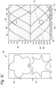
- Figures 3A-3D shows the rotors and the compression chamber of an example embodiment of a screw compressor 50 at a series of compression angles corresponding to opening and closure of economizer ports as the male rotor 52 and female rotor 54 of the screw compressor 50 rotate.
- the compression angle is the current angle of the rotors with respect to a reference position.
- the reference position may be a position where the center of the male rotor 52, the center of the female rotor 54, and a tip of a lobe of the male rotor 52 are in line with one another, and the compression angle may be defined as an angle between that line and the current position of the tip of the lobe of male rotor 52 with respect to the center of male rotor 52.
- each compression chamber 56 is formed by one of the lobes of the male rotor 52 and one of the depressions in the female rotor over about 72 degrees of rotation in the compression angle.
- the angle over which the compression chamber 56 is formed may vary, for example being 360 degrees divided by the number of lobes of the male rotor.
- the compression angle of the screw compressor of this embodiment is at or about 25 degrees.
- the male trailing edge 58 of the male rotor 52 and the female trailing edge 60 of the female rotor 54 have each just passed where the compressor chamber 56 is sealed from the suction end 62 of the compressor housing 64.
- the male leading edge 66 of the male rotor 52 begins to pass the male side economizer port 68.
- the female leading edge 70 of the female rotor 54 begins to pass the female side economizer port 72.
- the male side economizer port 68 and the female side economizer port 72 each provide gas to the compression chamber 56 as the leading edges pass the economizer ports 68, 72 and expose the economizer ports 68, 72 to the compression chamber 56.
- each of the male side economizer port 68 and the female side economizer port 72 to the compression chamber 56 each occur at equal compression angles.
- the opening of the male side economizer port and the female side economizer port may occur at different compression angles.
- the closing of the male side economizer port and the female side economizer port may occur at different compression angles.
- the difference in compression angles for opening male and female side economizer ports and/or closing male and female may be up to or about half of the angular width of a lobe of the male rotor.
- the angular width of a lobe of a male rotor is 360 degrees divided by the number of lobes of the male rotor, e.g. 180 degrees for a two lobe rotor, or 60 degrees for a six lobe rotor.
- the opening compression angle of the male side economizer port and the opening compression angle of the female side economizer port are within ⁇ 36 degrees of one another in a compressor where the male rotor has 5 lobes
- Compressor housing 90 includes a male rotor cavity 92, a female rotor cavity 94, a male side economizer port 96 and a female side economizer port 98.
- Compressor housing 90 has a suction end 100 and a discharge end 102.
- Male side economizer port 96 and female side economizer port 98 are each located on the compressor housing such that they are following where a compression chamber is sealed from the suction end 100 by compressor housing 90, for example at a position at or about 5 to at or about 10 degrees of rotor rotation following where the compression chamber is sealed from suction end 100 by a male rotor in male rotor cavity 92, a female rotor in female rotor cavity 94, and compressor housing 90.
- FIG. 4B shows a compressor housing according to another embodiment.
- compressor housing 110 includes female side economizer port 112, located on boss 114 on the female rotor cavity 94 side of the compressor housing 110.
- Boss 114 extends outwards from the surface of compressor housing 110.
- the male side economizer port 116 is located on a corresponding boss (not shown) on the male rotor cavity 92 side of the compressor housing 110, and extending outwards from the surface of the compressor housing 110.
- the male side economizer port 112 and the female side economizer port 114 are located on the compressor housing 110 such that they are following where a compression chamber is sealed from the suction end 100 by compressor housing 110, for example at a position at or about 5 to at or about 10 degrees of rotor rotation following where the compression chamber is sealed from suction end 100 by a male rotor in male rotor cavity 92, a female rotor in female rotor cavity 94, and compressor housing 110.
Landscapes
- Engineering & Computer Science (AREA)
- Mechanical Engineering (AREA)
- General Engineering & Computer Science (AREA)
- Applications Or Details Of Rotary Compressors (AREA)
Claims (9)
- Schraubenverdichter (10), umfassend:ein Verdichtergehäuse (16) mit einem Saugende (18) und einem Austrittsende (20);einen Hauptläufer (12), der in dem Verdichtergehäuse auf einer Hauptläuferseite angeordnet ist;einen Nebenläufer (14), der in dem Verdichtergehäuse auf einer Nebenläuferseite angeordnet und dazu ausgelegt ist, den Hauptläufer in Eingriff zu bringen;einen ersten Vorwärmeranschluss (32) auf der Hauptläuferseite des Verdichtergehäuses; und einen zweiten Vorwärmeranschluss (34) auf der Nebenläuferseite des Verdichtergehäuses, wobei der erste Vorwärmeranschluss und der zweite Vorwärmeranschluss dazu ausgelegt sind, gleichzeitig Gas zu einer durch den Hauptläufer und den Nebenläufer gebildeten Verdichtungskammer (30) bereitzustellen;wobei der erste Vorwärmeranschluss und der zweite Vorwärmeranschluss jeweils Löcher und nicht Schlitze sind;wobei der erste Vorwärmeranschluss dazu ausgelegt ist, sich bei einem ersten Verdichtungsschließwinkel zu schließen, und der zweite Vorwärmeranschluss dazu ausgelegt ist, sich bei einem zweiten Verdichtungsschließwinkel zu schließen, wobei die Differenz zwischen dem ersten Verdichtungsschließwinkel und dem zweiten Verdichtungsschließwinkel kleiner als eine Hälfte einer Winkelbreite eines Nockens des Hauptläufers ist, dadurch gekennzeichnet, dass der erste Vorwärmeranschluss und der zweite Vorwärmeranschluss jeweils zwischen 5 und 10 Grad einer Läuferdrehung nach einer Position angeordnet sind, in der die Verdichtungskammer durch das Verdichtergehäuse von dem Saugende (18) abgedichtet ist.
- Schraubenverdichter nach Anspruch 1, wobei der erste Vorwärmeranschluss dazu ausgelegt ist, sich bei einem ersten Verdichtungsöffnungswinkel zu öffnen, und der zweite Vorwärmeranschluss dazu ausgelegt ist, sich bei einem zweiten Verdichtungsöffnungswinkel zu öffnen, wobei die Differenz zwischen dem ersten Verdichtungsöffnungswinkel und dem zweiten Verdichtungsöffnungswinkel kleiner als eine Hälfte einer Winkelbreite eines Nockens des Hauptläufers ist.
- Schraubenverdichter nach Anspruch 2, wobei der erste Verdichtungsöffnungswinkel und der zweite Verdichtungsöffnungswinkel gleich sind.
- Schraubenverdichter nach Anspruch 1, wobei der erste Verdichtungsschließwinkel und der zweite Verdichtungsschließwinkel gleich sind.
- Verfahren zum Betreiben eines Schraubenverdichters nach Anspruch 1, dadurch gekennzeichnet, dass es Folgendes umfasst:Einspritzen eines Gasstroms in die Verdichtungskammer (30) über einen ersten Vorwärmeranschluss (32) auf einer Hauptläuferseite des Schraubenverdichters undEinspritzen eines Gasstroms in die Verdichtungskammer (30) über einen zweiten Vorwärmeranschluss (34) auf einer Nebenläuferseite des Schraubenverdichters, wobeider erste Vorwärmeranschluss und der zweite Vorwärmeranschluss den Gasstrom gleichzeitig zu der Verdichtungskammer bereitstellen;wobei der erste Vorwärmeranschluss und der zweite Vorwärmeranschluss jeweils Löcher und nicht Schlitze sind;der erste Vorwärmeranschluss und der zweite Vorwärmeranschluss zwischen 5 und 10 Grad einer Läuferdrehung nach einer Position angeordnet sind, in der die Verdichtungskammer durch das Verdichtergehäuse von dem Saugende (18) abgedichtet ist, undsich der erste Vorwärmeranschluss bei einem ersten Verdichtungsschließwinkel schließt und sich der zweite Vorwärmeranschluss bei einem zweiten Verdichtungsschließwinkel schließt, wobei die Differenz zwischen dem ersten Verdichtungsschließwinkel und dem zweiten Verdichtungsschließwinkel kleiner als eine Hälfte einer Winkelbreite eines Nockens des Hauptläufers ist.
- Verfahren nach Anspruch 5, wobei sich der erste Vorwärmeranschluss bei einem ersten Verdichtungsöffnungswinkel öffnet, und sich der zweite Vorwärmeranschluss bei einem zweiten Verdichtungsöffnungswinkel öffnet, wobei die Differenz zwischen dem ersten Verdichtungsöffnungswinkel und dem zweiten Verdichtungsöffnungswinkel kleiner als eine Hälfte einer Winkelbreite eines Nockens des Hauptläufers ist.
- Verfahren nach Anspruch 6, wobei der erste Verdichtungsöffnungswinkel und der zweite Verdichtungsöffnungswinkel gleich sind.
- Verfahren nach Anspruch 5, wobei der erste Verdichtungsschließwinkel und der zweite Verdichtungsschließwinkel gleich sind.
- HVACR-System, umfassend den Schraubenverdichter nach einem der Ansprüche 1-4.
Applications Claiming Priority (1)
| Application Number | Priority Date | Filing Date | Title |
|---|---|---|---|
| US15/958,858 US10895259B2 (en) | 2018-04-20 | 2018-04-20 | Screw compressor having synchronized economizer ports |
Publications (2)
| Publication Number | Publication Date |
|---|---|
| EP3557062A1 EP3557062A1 (de) | 2019-10-23 |
| EP3557062B1 true EP3557062B1 (de) | 2023-12-27 |
Family
ID=66239993
Family Applications (1)
| Application Number | Title | Priority Date | Filing Date |
|---|---|---|---|
| EP19170424.6A Active EP3557062B1 (de) | 2018-04-20 | 2019-04-19 | Schraubenverdichter mit synchronisierten vorwärmeranschlüssen |
Country Status (3)
| Country | Link |
|---|---|
| US (1) | US10895259B2 (de) |
| EP (1) | EP3557062B1 (de) |
| CN (1) | CN110388319B (de) |
Families Citing this family (1)
| Publication number | Priority date | Publication date | Assignee | Title |
|---|---|---|---|---|
| IT202100019787A1 (it) * | 2021-07-26 | 2023-01-26 | Fluid O Tech Srl | Pompa a viti perfezionata, particolarmente per sistemi di raffreddamento. |
Family Cites Families (15)
| Publication number | Priority date | Publication date | Assignee | Title |
|---|---|---|---|---|
| USRE30499E (en) * | 1974-11-19 | 1981-02-03 | Dunham-Bush, Inc. | Injection cooling of screw compressors |
| JPH07117052B2 (ja) * | 1991-04-12 | 1995-12-18 | 株式会社神戸製鋼所 | 無給油式注液形スクリュ圧縮機 |
| EP0564123A1 (de) | 1992-04-02 | 1993-10-06 | Carrier Corporation | Kühlsystem |
| DE19543691A1 (de) | 1995-11-23 | 1997-05-28 | Bitzer Kuehlmaschinenbau Gmbh | Schraubenverdichter |
| US6571576B1 (en) | 2002-04-04 | 2003-06-03 | Carrier Corporation | Injection of liquid and vapor refrigerant through economizer ports |
| US6694750B1 (en) | 2002-08-21 | 2004-02-24 | Carrier Corporation | Refrigeration system employing multiple economizer circuits |
| DE10326467B4 (de) | 2003-06-12 | 2018-10-25 | Gea Refrigeration Germany Gmbh | Schraubenverdichter mit Economiser-Anschlussöffnung |
| DE10334947B4 (de) | 2003-07-31 | 2019-11-07 | Gea Refrigeration Germany Gmbh | Verdichter für transkritische Kälteanlagen |
| JP4140488B2 (ja) * | 2003-09-09 | 2008-08-27 | ダイキン工業株式会社 | スクリュー圧縮機および冷凍装置 |
| CN101925745B (zh) | 2008-01-23 | 2013-04-10 | 大金工业株式会社 | 螺杆压缩机 |
| US9086067B2 (en) | 2010-10-29 | 2015-07-21 | Daikin Industries, Ltd. | Screw compressor |
| CN104838144B (zh) | 2012-09-27 | 2017-11-10 | 爱尔特制造有限公司 | 用于增强压缩机效率的装置和方法 |
| WO2014106252A1 (en) * | 2012-12-31 | 2014-07-03 | Trane International Inc. | Economizer injection assembly and method |
| US20160161153A1 (en) * | 2013-07-10 | 2016-06-09 | Carrier Corporation | Screw compressor with economizer port |
| RU2737072C2 (ru) | 2015-08-11 | 2020-11-24 | Кэрриер Корпорейшн | Компрессор, способ его использования и система паровой компрессии |
-
2018
- 2018-04-20 US US15/958,858 patent/US10895259B2/en active Active
-
2019
- 2019-04-19 CN CN201910319749.5A patent/CN110388319B/zh active Active
- 2019-04-19 EP EP19170424.6A patent/EP3557062B1/de active Active
Also Published As
| Publication number | Publication date |
|---|---|
| US20190323503A1 (en) | 2019-10-24 |
| CN110388319B (zh) | 2022-12-06 |
| CN110388319A (zh) | 2019-10-29 |
| EP3557062A1 (de) | 2019-10-23 |
| US10895259B2 (en) | 2021-01-19 |
Similar Documents
| Publication | Publication Date | Title |
|---|---|---|
| US9528514B2 (en) | Gas compressor having an asymmetric cylinder chamber | |
| US20150147216A1 (en) | Gas compressor | |
| CA2885727C (en) | Apparatus and method for enhancing compressor efficiency | |
| US20160333877A1 (en) | Gas compressor | |
| CN104302923A (zh) | 气体压缩机 | |
| US9057373B2 (en) | Single screw compressor with high output | |
| US10677246B2 (en) | Variable volume ratio compressor | |
| US20180356128A1 (en) | Converting compressor to variable vi compressor | |
| US7802974B2 (en) | Screw compressor having asymmetric seal around rotor axis | |
| EP3557062B1 (de) | Schraubenverdichter mit synchronisierten vorwärmeranschlüssen | |
| US8956135B2 (en) | Screw compressor with asymmetric ports | |
| CN115126696B (zh) | 压缩机泵体、压缩机及温度调节系统 | |
| US20220049700A1 (en) | Screw Compressor | |
| KR20050060561A (ko) | 용량가변 회전압축기 | |
| CN111379706A (zh) | 用于螺杆压缩机的润滑剂注入 | |
| CN215521263U (zh) | 一种压缩组件、旋转式压缩机及制冷装置 | |
| US20040156735A1 (en) | Compressor | |
| US20050112009A1 (en) | Variable capacity rotary compressor | |
| CN115126697B (zh) | 压缩机泵体、压缩机及温度调节系统 | |
| JP2013194575A (ja) | スクロール型圧縮機 | |
| US11022122B2 (en) | Intermediate discharge port for a compressor | |
| KR100507979B1 (ko) | 용량가변 회전압축기 | |
| AU2004324084B2 (en) | Screw compressor seal | |
| HK1157427B (en) | Screw compressor with asymmetric ports |
Legal Events
| Date | Code | Title | Description |
|---|---|---|---|
| PUAI | Public reference made under article 153(3) epc to a published international application that has entered the european phase |
Free format text: ORIGINAL CODE: 0009012 |
|
| STAA | Information on the status of an ep patent application or granted ep patent |
Free format text: STATUS: THE APPLICATION HAS BEEN PUBLISHED |
|
| AK | Designated contracting states |
Kind code of ref document: A1 Designated state(s): AL AT BE BG CH CY CZ DE DK EE ES FI FR GB GR HR HU IE IS IT LI LT LU LV MC MK MT NL NO PL PT RO RS SE SI SK SM TR |
|
| AX | Request for extension of the european patent |
Extension state: BA ME |
|
| STAA | Information on the status of an ep patent application or granted ep patent |
Free format text: STATUS: REQUEST FOR EXAMINATION WAS MADE |
|
| 17P | Request for examination filed |
Effective date: 20200430 |
|
| RBV | Designated contracting states (corrected) |
Designated state(s): AL AT BE BG CH CY CZ DE DK EE ES FI FR GB GR HR HU IE IS IT LI LT LU LV MC MK MT NL NO PL PT RO RS SE SI SK SM TR |
|
| STAA | Information on the status of an ep patent application or granted ep patent |
Free format text: STATUS: EXAMINATION IS IN PROGRESS |
|
| 17Q | First examination report despatched |
Effective date: 20220309 |
|
| GRAP | Despatch of communication of intention to grant a patent |
Free format text: ORIGINAL CODE: EPIDOSNIGR1 |
|
| STAA | Information on the status of an ep patent application or granted ep patent |
Free format text: STATUS: GRANT OF PATENT IS INTENDED |
|
| INTG | Intention to grant announced |
Effective date: 20230714 |
|
| GRAS | Grant fee paid |
Free format text: ORIGINAL CODE: EPIDOSNIGR3 |
|
| GRAA | (expected) grant |
Free format text: ORIGINAL CODE: 0009210 |
|
| STAA | Information on the status of an ep patent application or granted ep patent |
Free format text: STATUS: THE PATENT HAS BEEN GRANTED |
|
| AK | Designated contracting states |
Kind code of ref document: B1 Designated state(s): AL AT BE BG CH CY CZ DE DK EE ES FI FR GB GR HR HU IE IS IT LI LT LU LV MC MK MT NL NO PL PT RO RS SE SI SK SM TR |
|
| REG | Reference to a national code |
Ref country code: GB Ref legal event code: FG4D |
|
| REG | Reference to a national code |
Ref country code: CH Ref legal event code: EP |
|
| REG | Reference to a national code |
Ref country code: DE Ref legal event code: R096 Ref document number: 602019043855 Country of ref document: DE |
|
| REG | Reference to a national code |
Ref country code: IE Ref legal event code: FG4D |
|
| P01 | Opt-out of the competence of the unified patent court (upc) registered |
Effective date: 20231220 |
|
| PG25 | Lapsed in a contracting state [announced via postgrant information from national office to epo] |
Ref country code: GR Free format text: LAPSE BECAUSE OF FAILURE TO SUBMIT A TRANSLATION OF THE DESCRIPTION OR TO PAY THE FEE WITHIN THE PRESCRIBED TIME-LIMIT Effective date: 20240328 |
|
| REG | Reference to a national code |
Ref country code: LT Ref legal event code: MG9D |
|
| PG25 | Lapsed in a contracting state [announced via postgrant information from national office to epo] |
Ref country code: LT Free format text: LAPSE BECAUSE OF FAILURE TO SUBMIT A TRANSLATION OF THE DESCRIPTION OR TO PAY THE FEE WITHIN THE PRESCRIBED TIME-LIMIT Effective date: 20231227 |
|
| PG25 | Lapsed in a contracting state [announced via postgrant information from national office to epo] |
Ref country code: ES Free format text: LAPSE BECAUSE OF FAILURE TO SUBMIT A TRANSLATION OF THE DESCRIPTION OR TO PAY THE FEE WITHIN THE PRESCRIBED TIME-LIMIT Effective date: 20231227 |
|
| PG25 | Lapsed in a contracting state [announced via postgrant information from national office to epo] |
Ref country code: LT Free format text: LAPSE BECAUSE OF FAILURE TO SUBMIT A TRANSLATION OF THE DESCRIPTION OR TO PAY THE FEE WITHIN THE PRESCRIBED TIME-LIMIT Effective date: 20231227 Ref country code: GR Free format text: LAPSE BECAUSE OF FAILURE TO SUBMIT A TRANSLATION OF THE DESCRIPTION OR TO PAY THE FEE WITHIN THE PRESCRIBED TIME-LIMIT Effective date: 20240328 Ref country code: FI Free format text: LAPSE BECAUSE OF FAILURE TO SUBMIT A TRANSLATION OF THE DESCRIPTION OR TO PAY THE FEE WITHIN THE PRESCRIBED TIME-LIMIT Effective date: 20231227 Ref country code: ES Free format text: LAPSE BECAUSE OF FAILURE TO SUBMIT A TRANSLATION OF THE DESCRIPTION OR TO PAY THE FEE WITHIN THE PRESCRIBED TIME-LIMIT Effective date: 20231227 Ref country code: BG Free format text: LAPSE BECAUSE OF FAILURE TO SUBMIT A TRANSLATION OF THE DESCRIPTION OR TO PAY THE FEE WITHIN THE PRESCRIBED TIME-LIMIT Effective date: 20240327 |
|
| REG | Reference to a national code |
Ref country code: NL Ref legal event code: MP Effective date: 20231227 |
|
| REG | Reference to a national code |
Ref country code: AT Ref legal event code: MK05 Ref document number: 1644758 Country of ref document: AT Kind code of ref document: T Effective date: 20231227 |
|
| PG25 | Lapsed in a contracting state [announced via postgrant information from national office to epo] |
Ref country code: NL Free format text: LAPSE BECAUSE OF FAILURE TO SUBMIT A TRANSLATION OF THE DESCRIPTION OR TO PAY THE FEE WITHIN THE PRESCRIBED TIME-LIMIT Effective date: 20231227 |
|
| PG25 | Lapsed in a contracting state [announced via postgrant information from national office to epo] |
Ref country code: SE Free format text: LAPSE BECAUSE OF FAILURE TO SUBMIT A TRANSLATION OF THE DESCRIPTION OR TO PAY THE FEE WITHIN THE PRESCRIBED TIME-LIMIT Effective date: 20231227 Ref country code: RS Free format text: LAPSE BECAUSE OF FAILURE TO SUBMIT A TRANSLATION OF THE DESCRIPTION OR TO PAY THE FEE WITHIN THE PRESCRIBED TIME-LIMIT Effective date: 20231227 Ref country code: NO Free format text: LAPSE BECAUSE OF FAILURE TO SUBMIT A TRANSLATION OF THE DESCRIPTION OR TO PAY THE FEE WITHIN THE PRESCRIBED TIME-LIMIT Effective date: 20240327 Ref country code: NL Free format text: LAPSE BECAUSE OF FAILURE TO SUBMIT A TRANSLATION OF THE DESCRIPTION OR TO PAY THE FEE WITHIN THE PRESCRIBED TIME-LIMIT Effective date: 20231227 Ref country code: LV Free format text: LAPSE BECAUSE OF FAILURE TO SUBMIT A TRANSLATION OF THE DESCRIPTION OR TO PAY THE FEE WITHIN THE PRESCRIBED TIME-LIMIT Effective date: 20231227 Ref country code: HR Free format text: LAPSE BECAUSE OF FAILURE TO SUBMIT A TRANSLATION OF THE DESCRIPTION OR TO PAY THE FEE WITHIN THE PRESCRIBED TIME-LIMIT Effective date: 20231227 |
|
| PG25 | Lapsed in a contracting state [announced via postgrant information from national office to epo] |
Ref country code: IS Free format text: LAPSE BECAUSE OF FAILURE TO SUBMIT A TRANSLATION OF THE DESCRIPTION OR TO PAY THE FEE WITHIN THE PRESCRIBED TIME-LIMIT Effective date: 20240427 |
|
| PG25 | Lapsed in a contracting state [announced via postgrant information from national office to epo] |
Ref country code: CZ Free format text: LAPSE BECAUSE OF FAILURE TO SUBMIT A TRANSLATION OF THE DESCRIPTION OR TO PAY THE FEE WITHIN THE PRESCRIBED TIME-LIMIT Effective date: 20231227 Ref country code: AT Free format text: LAPSE BECAUSE OF FAILURE TO SUBMIT A TRANSLATION OF THE DESCRIPTION OR TO PAY THE FEE WITHIN THE PRESCRIBED TIME-LIMIT Effective date: 20231227 |
|
| PG25 | Lapsed in a contracting state [announced via postgrant information from national office to epo] |
Ref country code: SK Free format text: LAPSE BECAUSE OF FAILURE TO SUBMIT A TRANSLATION OF THE DESCRIPTION OR TO PAY THE FEE WITHIN THE PRESCRIBED TIME-LIMIT Effective date: 20231227 |
|
| PG25 | Lapsed in a contracting state [announced via postgrant information from national office to epo] |
Ref country code: SM Free format text: LAPSE BECAUSE OF FAILURE TO SUBMIT A TRANSLATION OF THE DESCRIPTION OR TO PAY THE FEE WITHIN THE PRESCRIBED TIME-LIMIT Effective date: 20231227 Ref country code: SK Free format text: LAPSE BECAUSE OF FAILURE TO SUBMIT A TRANSLATION OF THE DESCRIPTION OR TO PAY THE FEE WITHIN THE PRESCRIBED TIME-LIMIT Effective date: 20231227 Ref country code: RO Free format text: LAPSE BECAUSE OF FAILURE TO SUBMIT A TRANSLATION OF THE DESCRIPTION OR TO PAY THE FEE WITHIN THE PRESCRIBED TIME-LIMIT Effective date: 20231227 Ref country code: IT Free format text: LAPSE BECAUSE OF FAILURE TO SUBMIT A TRANSLATION OF THE DESCRIPTION OR TO PAY THE FEE WITHIN THE PRESCRIBED TIME-LIMIT Effective date: 20231227 Ref country code: IS Free format text: LAPSE BECAUSE OF FAILURE TO SUBMIT A TRANSLATION OF THE DESCRIPTION OR TO PAY THE FEE WITHIN THE PRESCRIBED TIME-LIMIT Effective date: 20240427 Ref country code: EE Free format text: LAPSE BECAUSE OF FAILURE TO SUBMIT A TRANSLATION OF THE DESCRIPTION OR TO PAY THE FEE WITHIN THE PRESCRIBED TIME-LIMIT Effective date: 20231227 Ref country code: CZ Free format text: LAPSE BECAUSE OF FAILURE TO SUBMIT A TRANSLATION OF THE DESCRIPTION OR TO PAY THE FEE WITHIN THE PRESCRIBED TIME-LIMIT Effective date: 20231227 Ref country code: AT Free format text: LAPSE BECAUSE OF FAILURE TO SUBMIT A TRANSLATION OF THE DESCRIPTION OR TO PAY THE FEE WITHIN THE PRESCRIBED TIME-LIMIT Effective date: 20231227 |
|
| PG25 | Lapsed in a contracting state [announced via postgrant information from national office to epo] |
Ref country code: PL Free format text: LAPSE BECAUSE OF FAILURE TO SUBMIT A TRANSLATION OF THE DESCRIPTION OR TO PAY THE FEE WITHIN THE PRESCRIBED TIME-LIMIT Effective date: 20231227 Ref country code: PT Free format text: LAPSE BECAUSE OF FAILURE TO SUBMIT A TRANSLATION OF THE DESCRIPTION OR TO PAY THE FEE WITHIN THE PRESCRIBED TIME-LIMIT Effective date: 20240429 |
|
| PG25 | Lapsed in a contracting state [announced via postgrant information from national office to epo] |
Ref country code: PT Free format text: LAPSE BECAUSE OF FAILURE TO SUBMIT A TRANSLATION OF THE DESCRIPTION OR TO PAY THE FEE WITHIN THE PRESCRIBED TIME-LIMIT Effective date: 20240429 Ref country code: PL Free format text: LAPSE BECAUSE OF FAILURE TO SUBMIT A TRANSLATION OF THE DESCRIPTION OR TO PAY THE FEE WITHIN THE PRESCRIBED TIME-LIMIT Effective date: 20231227 |
|
| REG | Reference to a national code |
Ref country code: DE Ref legal event code: R097 Ref document number: 602019043855 Country of ref document: DE |
|
| PG25 | Lapsed in a contracting state [announced via postgrant information from national office to epo] |
Ref country code: DK Free format text: LAPSE BECAUSE OF FAILURE TO SUBMIT A TRANSLATION OF THE DESCRIPTION OR TO PAY THE FEE WITHIN THE PRESCRIBED TIME-LIMIT Effective date: 20231227 |
|
| PG25 | Lapsed in a contracting state [announced via postgrant information from national office to epo] |
Ref country code: DK Free format text: LAPSE BECAUSE OF FAILURE TO SUBMIT A TRANSLATION OF THE DESCRIPTION OR TO PAY THE FEE WITHIN THE PRESCRIBED TIME-LIMIT Effective date: 20231227 |
|
| PLBE | No opposition filed within time limit |
Free format text: ORIGINAL CODE: 0009261 |
|
| STAA | Information on the status of an ep patent application or granted ep patent |
Free format text: STATUS: NO OPPOSITION FILED WITHIN TIME LIMIT |
|
| PG25 | Lapsed in a contracting state [announced via postgrant information from national office to epo] |
Ref country code: MC Free format text: LAPSE BECAUSE OF FAILURE TO SUBMIT A TRANSLATION OF THE DESCRIPTION OR TO PAY THE FEE WITHIN THE PRESCRIBED TIME-LIMIT Effective date: 20231227 |
|
| PG25 | Lapsed in a contracting state [announced via postgrant information from national office to epo] |
Ref country code: MC Free format text: LAPSE BECAUSE OF FAILURE TO SUBMIT A TRANSLATION OF THE DESCRIPTION OR TO PAY THE FEE WITHIN THE PRESCRIBED TIME-LIMIT Effective date: 20231227 |
|
| REG | Reference to a national code |
Ref country code: CH Ref legal event code: PL |
|
| 26N | No opposition filed |
Effective date: 20240930 |
|
| PG25 | Lapsed in a contracting state [announced via postgrant information from national office to epo] |
Ref country code: LU Free format text: LAPSE BECAUSE OF NON-PAYMENT OF DUE FEES Effective date: 20240419 |
|
| REG | Reference to a national code |
Ref country code: BE Ref legal event code: MM Effective date: 20240430 |
|
| PG25 | Lapsed in a contracting state [announced via postgrant information from national office to epo] |
Ref country code: LU Free format text: LAPSE BECAUSE OF NON-PAYMENT OF DUE FEES Effective date: 20240419 |
|
| PG25 | Lapsed in a contracting state [announced via postgrant information from national office to epo] |
Ref country code: BE Free format text: LAPSE BECAUSE OF NON-PAYMENT OF DUE FEES Effective date: 20240430 |
|
| PG25 | Lapsed in a contracting state [announced via postgrant information from national office to epo] |
Ref country code: BE Free format text: LAPSE BECAUSE OF NON-PAYMENT OF DUE FEES Effective date: 20240430 Ref country code: CH Free format text: LAPSE BECAUSE OF NON-PAYMENT OF DUE FEES Effective date: 20240430 |
|
| PG25 | Lapsed in a contracting state [announced via postgrant information from national office to epo] |
Ref country code: IE Free format text: LAPSE BECAUSE OF NON-PAYMENT OF DUE FEES Effective date: 20240419 |
|
| PG25 | Lapsed in a contracting state [announced via postgrant information from national office to epo] |
Ref country code: SI Free format text: LAPSE BECAUSE OF FAILURE TO SUBMIT A TRANSLATION OF THE DESCRIPTION OR TO PAY THE FEE WITHIN THE PRESCRIBED TIME-LIMIT Effective date: 20231227 |
|
| PGFP | Annual fee paid to national office [announced via postgrant information from national office to epo] |
Ref country code: FR Payment date: 20250319 Year of fee payment: 7 |
|
| PGFP | Annual fee paid to national office [announced via postgrant information from national office to epo] |
Ref country code: GB Payment date: 20250319 Year of fee payment: 7 |
|
| PGFP | Annual fee paid to national office [announced via postgrant information from national office to epo] |
Ref country code: DE Payment date: 20250319 Year of fee payment: 7 |
|
| PG25 | Lapsed in a contracting state [announced via postgrant information from national office to epo] |
Ref country code: CY Free format text: LAPSE BECAUSE OF FAILURE TO SUBMIT A TRANSLATION OF THE DESCRIPTION OR TO PAY THE FEE WITHIN THE PRESCRIBED TIME-LIMIT; INVALID AB INITIO Effective date: 20190419 |
|
| PG25 | Lapsed in a contracting state [announced via postgrant information from national office to epo] |
Ref country code: HU Free format text: LAPSE BECAUSE OF FAILURE TO SUBMIT A TRANSLATION OF THE DESCRIPTION OR TO PAY THE FEE WITHIN THE PRESCRIBED TIME-LIMIT; INVALID AB INITIO Effective date: 20190419 |