EP3557061B1 - Flüssigkeitspumpenanordnung - Google Patents
Flüssigkeitspumpenanordnung Download PDFInfo
- Publication number
- EP3557061B1 EP3557061B1 EP19169961.0A EP19169961A EP3557061B1 EP 3557061 B1 EP3557061 B1 EP 3557061B1 EP 19169961 A EP19169961 A EP 19169961A EP 3557061 B1 EP3557061 B1 EP 3557061B1
- Authority
- EP
- European Patent Office
- Prior art keywords
- motor
- enclosure
- assembly
- motor enclosure
- heat sink
- Prior art date
- Legal status (The legal status is an assumption and is not a legal conclusion. Google has not performed a legal analysis and makes no representation as to the accuracy of the status listed.)
- Active
Links
Images


Classifications
-
- F—MECHANICAL ENGINEERING; LIGHTING; HEATING; WEAPONS; BLASTING
- F04—POSITIVE - DISPLACEMENT MACHINES FOR LIQUIDS; PUMPS FOR LIQUIDS OR ELASTIC FLUIDS
- F04B—POSITIVE-DISPLACEMENT MACHINES FOR LIQUIDS; PUMPS
- F04B53/00—Component parts, details or accessories not provided for in, or of interest apart from, groups F04B1/00 - F04B23/00 or F04B39/00 - F04B47/00
- F04B53/16—Casings; Cylinders; Cylinder liners or heads; Fluid connections
-
- F—MECHANICAL ENGINEERING; LIGHTING; HEATING; WEAPONS; BLASTING
- F04—POSITIVE - DISPLACEMENT MACHINES FOR LIQUIDS; PUMPS FOR LIQUIDS OR ELASTIC FLUIDS
- F04D—NON-POSITIVE-DISPLACEMENT PUMPS
- F04D25/00—Pumping installations or systems
- F04D25/02—Units comprising pumps and their driving means
- F04D25/08—Units comprising pumps and their driving means the working fluid being air, e.g. for ventilation
- F04D25/082—Units comprising pumps and their driving means the working fluid being air, e.g. for ventilation the unit having provision for cooling the motor
-
- H—ELECTRICITY
- H02—GENERATION; CONVERSION OR DISTRIBUTION OF ELECTRIC POWER
- H02K—DYNAMO-ELECTRIC MACHINES
- H02K5/00—Casings; Enclosures; Supports
- H02K5/04—Casings or enclosures characterised by the shape, form or construction thereof
-
- F—MECHANICAL ENGINEERING; LIGHTING; HEATING; WEAPONS; BLASTING
- F02—COMBUSTION ENGINES; HOT-GAS OR COMBUSTION-PRODUCT ENGINE PLANTS
- F02M—SUPPLYING COMBUSTION ENGINES IN GENERAL WITH COMBUSTIBLE MIXTURES OR CONSTITUENTS THEREOF
- F02M37/00—Apparatus or systems for feeding liquid fuel from storage containers to carburettors or fuel-injection apparatus; Arrangements for purifying liquid fuel specially adapted for, or arranged on, internal-combustion engines
- F02M37/04—Feeding by means of driven pumps
- F02M37/08—Feeding by means of driven pumps electrically driven
- F02M37/10—Feeding by means of driven pumps electrically driven submerged in fuel, e.g. in reservoir
-
- F—MECHANICAL ENGINEERING; LIGHTING; HEATING; WEAPONS; BLASTING
- F04—POSITIVE - DISPLACEMENT MACHINES FOR LIQUIDS; PUMPS FOR LIQUIDS OR ELASTIC FLUIDS
- F04C—ROTARY-PISTON, OR OSCILLATING-PISTON, POSITIVE-DISPLACEMENT MACHINES FOR LIQUIDS; ROTARY-PISTON, OR OSCILLATING-PISTON, POSITIVE-DISPLACEMENT PUMPS
- F04C14/00—Control of, monitoring of, or safety arrangements for, machines, pumps or pumping installations
- F04C14/28—Safety arrangements; Monitoring
-
- F—MECHANICAL ENGINEERING; LIGHTING; HEATING; WEAPONS; BLASTING
- F04—POSITIVE - DISPLACEMENT MACHINES FOR LIQUIDS; PUMPS FOR LIQUIDS OR ELASTIC FLUIDS
- F04C—ROTARY-PISTON, OR OSCILLATING-PISTON, POSITIVE-DISPLACEMENT MACHINES FOR LIQUIDS; ROTARY-PISTON, OR OSCILLATING-PISTON, POSITIVE-DISPLACEMENT PUMPS
- F04C15/00—Component parts, details or accessories of machines, pumps or pumping installations, not provided for in groups F04C2/00 - F04C14/00
- F04C15/0057—Driving elements, brakes, couplings, transmission specially adapted for machines or pumps
- F04C15/008—Prime movers
-
- F—MECHANICAL ENGINEERING; LIGHTING; HEATING; WEAPONS; BLASTING
- F04—POSITIVE - DISPLACEMENT MACHINES FOR LIQUIDS; PUMPS FOR LIQUIDS OR ELASTIC FLUIDS
- F04D—NON-POSITIVE-DISPLACEMENT PUMPS
- F04D13/00—Pumping installations or systems
- F04D13/02—Units comprising pumps and their driving means
- F04D13/06—Units comprising pumps and their driving means the pump being electrically driven
- F04D13/0646—Units comprising pumps and their driving means the pump being electrically driven the hollow pump or motor shaft being the conduit for the working fluid
-
- F—MECHANICAL ENGINEERING; LIGHTING; HEATING; WEAPONS; BLASTING
- F04—POSITIVE - DISPLACEMENT MACHINES FOR LIQUIDS; PUMPS FOR LIQUIDS OR ELASTIC FLUIDS
- F04D—NON-POSITIVE-DISPLACEMENT PUMPS
- F04D29/00—Details, component parts, or accessories
- F04D29/40—Casings; Connections of working fluid
- F04D29/42—Casings; Connections of working fluid for radial or helico-centrifugal pumps
- F04D29/426—Casings; Connections of working fluid for radial or helico-centrifugal pumps especially adapted for liquid pumps
-
- F—MECHANICAL ENGINEERING; LIGHTING; HEATING; WEAPONS; BLASTING
- F04—POSITIVE - DISPLACEMENT MACHINES FOR LIQUIDS; PUMPS FOR LIQUIDS OR ELASTIC FLUIDS
- F04D—NON-POSITIVE-DISPLACEMENT PUMPS
- F04D29/00—Details, component parts, or accessories
- F04D29/58—Cooling; Heating; Diminishing heat transfer
- F04D29/5806—Cooling the drive system
-
- F—MECHANICAL ENGINEERING; LIGHTING; HEATING; WEAPONS; BLASTING
- F04—POSITIVE - DISPLACEMENT MACHINES FOR LIQUIDS; PUMPS FOR LIQUIDS OR ELASTIC FLUIDS
- F04D—NON-POSITIVE-DISPLACEMENT PUMPS
- F04D29/00—Details, component parts, or accessories
- F04D29/58—Cooling; Heating; Diminishing heat transfer
- F04D29/582—Cooling; Heating; Diminishing heat transfer specially adapted for elastic fluid pumps
- F04D29/584—Cooling; Heating; Diminishing heat transfer specially adapted for elastic fluid pumps cooling or heating the machine
-
- H—ELECTRICITY
- H02—GENERATION; CONVERSION OR DISTRIBUTION OF ELECTRIC POWER
- H02K—DYNAMO-ELECTRIC MACHINES
- H02K11/00—Structural association of dynamo-electric machines with electric components or with devices for shielding, monitoring or protection
- H02K11/01—Structural association of dynamo-electric machines with electric components or with devices for shielding, monitoring or protection for shielding from electromagnetic fields, i.e. structural association with shields
-
- H—ELECTRICITY
- H02—GENERATION; CONVERSION OR DISTRIBUTION OF ELECTRIC POWER
- H02K—DYNAMO-ELECTRIC MACHINES
- H02K11/00—Structural association of dynamo-electric machines with electric components or with devices for shielding, monitoring or protection
- H02K11/20—Structural association of dynamo-electric machines with electric components or with devices for shielding, monitoring or protection for measuring, monitoring, testing, protecting or switching
- H02K11/21—Devices for sensing speed or position, or actuated thereby
- H02K11/215—Magnetic effect devices, e.g. Hall-effect or magneto-resistive elements
-
- H—ELECTRICITY
- H02—GENERATION; CONVERSION OR DISTRIBUTION OF ELECTRIC POWER
- H02K—DYNAMO-ELECTRIC MACHINES
- H02K11/00—Structural association of dynamo-electric machines with electric components or with devices for shielding, monitoring or protection
- H02K11/30—Structural association with control circuits or drive circuits
- H02K11/33—Drive circuits, e.g. power electronics
-
- H—ELECTRICITY
- H02—GENERATION; CONVERSION OR DISTRIBUTION OF ELECTRIC POWER
- H02K—DYNAMO-ELECTRIC MACHINES
- H02K5/00—Casings; Enclosures; Supports
- H02K5/04—Casings or enclosures characterised by the shape, form or construction thereof
- H02K5/12—Casings or enclosures characterised by the shape, form or construction thereof specially adapted for operating in liquid or gas
- H02K5/136—Casings or enclosures characterised by the shape, form or construction thereof specially adapted for operating in liquid or gas explosion-proof
-
- H—ELECTRICITY
- H02—GENERATION; CONVERSION OR DISTRIBUTION OF ELECTRIC POWER
- H02K—DYNAMO-ELECTRIC MACHINES
- H02K7/00—Arrangements for handling mechanical energy structurally associated with dynamo-electric machines, e.g. structural association with mechanical driving motors or auxiliary dynamo-electric machines
- H02K7/14—Structural association with mechanical loads, e.g. with hand-held machine tools or fans
-
- H—ELECTRICITY
- H02—GENERATION; CONVERSION OR DISTRIBUTION OF ELECTRIC POWER
- H02K—DYNAMO-ELECTRIC MACHINES
- H02K9/00—Arrangements for cooling or ventilating
- H02K9/22—Arrangements for cooling or ventilating by solid heat conducting material embedded in, or arranged in contact with, the stator or rotor, e.g. heat bridges
-
- F—MECHANICAL ENGINEERING; LIGHTING; HEATING; WEAPONS; BLASTING
- F02—COMBUSTION ENGINES; HOT-GAS OR COMBUSTION-PRODUCT ENGINE PLANTS
- F02M—SUPPLYING COMBUSTION ENGINES IN GENERAL WITH COMBUSTIBLE MIXTURES OR CONSTITUENTS THEREOF
- F02M37/00—Apparatus or systems for feeding liquid fuel from storage containers to carburettors or fuel-injection apparatus; Arrangements for purifying liquid fuel specially adapted for, or arranged on, internal-combustion engines
- F02M37/04—Feeding by means of driven pumps
- F02M37/14—Feeding by means of driven pumps the pumps being combined with other apparatus
-
- F—MECHANICAL ENGINEERING; LIGHTING; HEATING; WEAPONS; BLASTING
- F04—POSITIVE - DISPLACEMENT MACHINES FOR LIQUIDS; PUMPS FOR LIQUIDS OR ELASTIC FLUIDS
- F04C—ROTARY-PISTON, OR OSCILLATING-PISTON, POSITIVE-DISPLACEMENT MACHINES FOR LIQUIDS; ROTARY-PISTON, OR OSCILLATING-PISTON, POSITIVE-DISPLACEMENT PUMPS
- F04C2/00—Rotary-piston machines or pumps
- F04C2/30—Rotary-piston machines or pumps having the characteristics covered by two or more groups F04C2/02, F04C2/08, F04C2/22, F04C2/24 or having the characteristics covered by one of these groups together with some other type of movement between co-operating members
- F04C2/34—Rotary-piston machines or pumps having the characteristics covered by two or more groups F04C2/02, F04C2/08, F04C2/22, F04C2/24 or having the characteristics covered by one of these groups together with some other type of movement between co-operating members having the movement defined in groups F04C2/08 or F04C2/22 and relative reciprocation between the co-operating members
- F04C2/344—Rotary-piston machines or pumps having the characteristics covered by two or more groups F04C2/02, F04C2/08, F04C2/22, F04C2/24 or having the characteristics covered by one of these groups together with some other type of movement between co-operating members having the movement defined in groups F04C2/08 or F04C2/22 and relative reciprocation between the co-operating members with vanes reciprocating with respect to the inner member
-
- F—MECHANICAL ENGINEERING; LIGHTING; HEATING; WEAPONS; BLASTING
- F04—POSITIVE - DISPLACEMENT MACHINES FOR LIQUIDS; PUMPS FOR LIQUIDS OR ELASTIC FLUIDS
- F04C—ROTARY-PISTON, OR OSCILLATING-PISTON, POSITIVE-DISPLACEMENT MACHINES FOR LIQUIDS; ROTARY-PISTON, OR OSCILLATING-PISTON, POSITIVE-DISPLACEMENT PUMPS
- F04C2240/00—Components
- F04C2240/30—Casings or housings
-
- F—MECHANICAL ENGINEERING; LIGHTING; HEATING; WEAPONS; BLASTING
- F04—POSITIVE - DISPLACEMENT MACHINES FOR LIQUIDS; PUMPS FOR LIQUIDS OR ELASTIC FLUIDS
- F04C—ROTARY-PISTON, OR OSCILLATING-PISTON, POSITIVE-DISPLACEMENT MACHINES FOR LIQUIDS; ROTARY-PISTON, OR OSCILLATING-PISTON, POSITIVE-DISPLACEMENT PUMPS
- F04C2240/00—Components
- F04C2240/40—Electric motor
-
- H—ELECTRICITY
- H02—GENERATION; CONVERSION OR DISTRIBUTION OF ELECTRIC POWER
- H02K—DYNAMO-ELECTRIC MACHINES
- H02K2211/00—Specific aspects not provided for in the other groups of this subclass relating to measuring or protective devices or electric components
- H02K2211/03—Machines characterised by circuit boards, e.g. pcb
Definitions
- the present disclosure is related to fluid transfer pump assemblies, and particularly to such pump assemblies that have heat dissipation, status feedback signals, and switching functionality in explosion-proof motor enclosure environments.
- Fluid transfer pumps move fluid from one location to another.
- a pump that moves hazardous fluid such as gasoline from a storage tank to a vehicle.
- the pump may employ vanes, diaphragms, or other like structures that are rotated or oscillated inside the pump via some motive force such as an electric motor.
- the vanes are located in a pump enclosure that is in fluid communication with inlet and outlet manifolds.
- the inlet manifold may also be in communication with the gasoline in the storage tank while the outlet manifold may also be attached to a hose or other structure configured to deliver the gasoline to another location.
- a vacuum is created in the pump enclosure to cause the gasoline already present in the tank to be drawn up through the inlet manifold.
- the vanes then rapidly push the gasoline out through the outlet manifold and the hose, to be delivered to the other location.
- a nozzle or other type of valve structure may be attached at the other end of the hose to selectively dispense the pumped gasoline.
- An electric motor is a suitable means for rotating the vanes inside the pump.
- the motor is also able to generate enough rotational velocity to effectively draw up and dispense the fluid at a sufficient rate.
- Fluids like gasoline may pose a risk when utilizing electric motors since such motors have a propensity to produce heat, sparks and arcs, and even flames during abnormal conditions. Placing such motors in potentially flammable environments can, therefore, be hazardous. That is why electric motors are housed in explosion-proof enclosures. These enclosures prevent any internal explosion from propagating to a surrounding explosive atmosphere.
- One manner of mitigating explosions that occur inside the motor enclosure from propagating to outside the motor enclosure is to provide a flame path at the joint between the motor enclosure and end bell.
- the flame path may be an extended seam located at the motor enclosure joint where the motor enclosure and end bell couple to each other.
- the end bell may include an extended flange sized to fit against an elongated collar on the motor enclosure. The result is a pathway located between the spaced-apart interior and exterior seams of the enclosure and end bell.
- the space between the extended flange and collar provides a pathway that will extinguish any flames generated by an explosion inside the enclosure. This prevents the explosion from reaching the external explosive environment thereby eliminating risk of igniting any flammable concentration of vapors outside of the enclosure.
- US 4,931,678 describes an electric motor for use in explosion-endangered environments.
- the motor is provided with an outwardly encapsulated motor housing made of thermally conducting material such as aluminium.
- the motor housing in turn is provided on its outer side with a shield of an electrically non-conducting material.
- the outer shielding of the motor housing prevents contact with metallic parts of the motor and thereby current conducting parts of the motor by a person servicing the device.
- GB 2 303 942 discloses an electrical motor comprising an encapsulated motor housing which is closed at both ends by bearing plates and in use is connected to earth potential.
- the housing is provided with cooling ribs arranged to form cooling air channels.
- Illustrative embodiments of this present disclosure provide multiple solutions for operating and enhancing the fluid pump motor located inside the explosion-proof motor enclosure, but without needing additional openings requiring additional flame paths, and, thus, additional costs.
- An illustrative embodiment of the present disclosure includes an explosion-proof motor enclosure that comprises a heat sink for efficiently transferring heat generated by components located within the enclosure, but without requiring openings in the enclosure.
- Another illustrative embodiment of the present disclosure comprises a status feedback signal system that conveys operating conditions of the motor, again, without requiring additional openings extend through the motor enclosure.
- Another illustrative embodiment of the present disclosure provides a switch system to activate and deactivate the electric motor. And yet again, this is accomplished without requiring additional openings in the motor enclosure.
- a fluid transfer pump assembly comprising: a motor enclosure assembly formed by a motor enclosure and an end bell; wherein the motor enclosure and the end bell join together to form a motor cavity sized to receive a motor; wherein the motor enclosure includes a collar that extends from the motor enclosure at a collar base, encircles a portion of the motor cavity, and terminates at a collar end distal from the collar base; wherein the collar includes a collar surface; wherein the end bell includes a flange that extends from the end bell at a flange base, encircles a portion of the motor cavity, and terminates at a flange end distal from the flange base; wherein the flange includes a flange surface; wherein when the motor enclosure and the end bell are joined together to form the motor cavity the collar surface faces the flange surface to form a flame path between the collar and flange surfaces; wherein when the motor enclosure and the end bell are joined together to form the motor cavity the collar base
- the fluid transfer pump assembly may further comprise: the motor cavity being cylindrical, the collar surface of the motor enclosure being cylindrical, and the flange surface of the end bell being cylindrical; the panel of the heat sink having a circular shape such that the end surface of the panel of the heat sink is located adjacent the cylindrical collar surface of the motor enclosure; the panel of the heat sink is located only interior of the motor enclosure assembly wherein no portion of the heat sink extends exterior of the motor enclosure assembly, and wherein no vents in the motor enclosure assembly are configured to dissipate heat from the heat-generating power conversion circuit board; a pump enclosure attached to the motor enclosure assembly; and the motor enclosure and end bell are both made of a heat-conducting material.
- a fluid transfer pump assembly comprising: a motor enclosure assembly that forms a motor cavity sized to receive a motor; wherein the motor enclosure includes a flame path composed of a pathway formed by two facing surfaces of the motor enclosure; wherein the pathway is formed by the two facing surfaces of the motor enclosure that extend from an interior joint to an exterior joint; wherein the interior joint faces the motor cavity and the exterior joint faces exterior of the motor enclosure assembly; and a heat sink located in the motor cavity of the motor enclosure assembly; wherein a portion of the heat sink abuts the interior joint; and wherein the heat sink does not interfere with the flame path extending from the interior joint to the exterior joint of the motor enclosure assembly.
- the fluid transfer pump assembly may further comprise: the motor enclosure assembly being composed of a first motor enclosure portion and a second motor enclosure portion; the first motor enclosure portion includes a first facing surface of the two facing surfaces, and the second motor enclosure portion includes a second facing surface of the two facing surfaces; the interior joint includes a first joint surface of the first motor enclosure portion and a second joint surface of the second motor enclosure surface; the portion of the heat sink that abuts the interior joint contacts both the first and second joint surfaces such that heat in the heat sink transfers to the first and second motor enclosure portions; the interior joint encircles the motor cavity, a cross-sectional profile of the motor cavity is circular, square, oval, quadrilateral, and polygonal; the first and second motor enclosure portions are separable; the portion of the heat sink that abuts the interior joint includes a periphery that extends about the perimeter of the heat sink; the periphery abuts the interior joint of the motor enclosure assembly; a heat generating power conversion circuit board
- a fluid transfer pump assembly comprising: a motor enclosure assembly that forms a motor cavity sized to receive a motor; wherein the motor enclosure includes a flame path; wherein the flame path extends from an interior joint to an exterior joint; wherein the interior joint faces the motor cavity and the exterior joint faces exterior of the motor enclosure assembly; and a heat sink located in the motor cavity of the motor enclosure assembly; wherein a portion of the heat sink abuts the interior joint; and wherein no portion of the heat sink extends exterior to the motor enclosure assembly.
- the fluid transfer pump assembly may further comprise: the heat sink does not interfere with the flame path that extends from the interior joint to the exterior joint; the motor cavity including a motor controller that supplies power to a motor having a rotor and a stator, wherein the stator includes a plurality of pole pairs of wire windings that create a moving electromagnetic force to rotate the rotor, wherein the motor controller upon receiving signals of a condition of the motor, directs current to at least one pole pair of wire windings at a voltage that does not cause the motor to rotate, but causes the at least one pole pair of wire windings to vibrate to create a status feedback signal; and the motor cavity includes a switch assembly that comprises at least one magnet located on a shield extending transverse from that magnet, a switch actuator located adjacent to the shield opposite the at least one magnet, wherein the switch is engageable with the magnet through the shield such that as the switch actuator moves the magnet moves, wherein the magnet fits into a space on the motor enclosure that is spaced
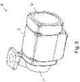
- FIG. 1 A front perspective view of illustrative pump assembly 2 is shown in Fig. 1 .
- fluid transfer pump 2 includes a motor enclosure 4, rear end bell 6, switch mechanism 8, pump enclosure 10, and manifolds 12.
- Motor enclosure 4 is part of an explosion-proof enclosure along with end bell 6 and pump enclosure 10 which prevents any sparks, arcs, and flames, from exiting the motor enclosure 4, rear end bell 6, and pump enclosure 10.
- Switch mechanism 8, which will be discussed in further detail with respect to Figs. 7 through 9 , is illustratively positioned on the exterior of motor enclosure 4 as shown.
- switch mechanism 8 is shown having a switch shaft assembly 14 attached to switch lever arm 16 via fastener 18.
- a switch lever handle 20 attached to switch lever arm 16 assists in operating switch mechanism 8.
- fluid transfer pump 2 may be configured to pump gasoline or other like hazardous materials in a similar manner to conventional gas station pumps.
- gas dispensing nozzles (not shown) may be employed with the fluid transfer pump 2 and operate in a similar method as their gas station fuel pump nozzle counterpart.
- pump enclosure 10 located adjacent motor enclosure 4 and capped with a rotor cover 26 via fasteners 28.
- pump enclosure 10 encloses a rotor and vanes that are rotated by an electric motor located in motor enclosure 4. The rotating vanes to draw up and expel fluid from inlet manifold portion 30 and out through outlet manifold portion 32.
- aesthetic joint covers 34 and 36 are also shown. These covers illustratively shroud the explosion-proof joints that exist between motor enclosure 4 and rear end bell 6, as well as motor enclosure 4 and pump enclosure 10.
- FIG. 2 A reverse perspective view of fluid transfer pump 2 is shown in Fig. 2 .
- This view also shows motor enclosure 4, rear end bell 6, pump enclosure 10, and manifold 12.
- the power supply port 42 through which a power cord enters to connect the power converter in motor enclosure 4 with an exterior power supply, such as a vehicle battery, AC mains, etc.
- fluid transfer pump 2 the primary components that make up the exterior body of fluid transfer pump 2 are the motor enclosure 4, rear end bell 6, and pump enclosure 10.
- Manifold 12 is indeed part of pump enclosure 10.
- rear end bell 6 and pump enclosure 10 may be attached to motor enclosure 4 via fasteners such as fastener 44 as shown.
- fastener 44 may be employed with the pump so long as the explosion-proof characteristics, as known in the relevant art, are not compromised by attaching the structures together.
- An important, albeit known, feature of fluid transfer pumps of the type like fluid transfer pump 2 is that it is specifically designed so that the motor located inside motor enclosure 4 will not produce any flame or explosion that can propagate outside of motor enclosure 4. A conventional way of achieving this is to make sure a flame path exists at each motor enclosure opening.
- an illustrative embodiment of the present disclosure provides explosion-proof containment between motor enclosure 4 and rear end bell 6. More specifically, an illustrative embodiment of the present disclosure provides a heat sink mechanism within motor enclosure 4 and rear end bell 6 that is capable of dissipating heat while not requiring additional openings in either the motor enclosure 4 or rear end bell 6 that would require adding more flame paths.
- the motor for use in this pump may be a brushless motor requiring a power converter.
- illustrative embodiment of this present disclosure provides a heat sink system that can transfer heat from the power conversion circuit board (or other structures) away from the internal structures in a motor enclosure without the use of any fans or venting.
- a heat sink plate may be placed in contact with the circuit board or any other structure that produces heat needing to be removed.
- the heat sink may be fitted between the interior joint portion of the motor enclosure and the interior joint portion of the rear end bell.
- the plate is in contact with other heat transfer materials (i.e., metal structures) on opposite sides of the heat sink.
- This metal to metal contact between the heat sink and both the motor enclosure and rear end bell gives increased surface area contact between structures which allows more heat to dissipate.
- having the heat sink sandwiched between the interior joint of the flame path of the enclosure means the heat sink has face-to-face contact for effective heat distribution while at the same time not interfering with the flame path structures or require any venting or fans.
- FIG. 3 A perspective exploded view of motor enclosure 4 and rear end bell 6 with selected components to be contained within are shown in Fig. 3 .
- a power conversion circuit board 46, heat sink, 48, and plug assembly 50 are shown to be contained within cavity 52 of motor enclosure 4.
- collar 54 that includes an inner periphery that forms a flame path surface 56.
- flange 58 extending from rear end bell 6 is flange 58 that includes its flame path surface 60 that will be positioned adjacent flame path surface 56 of collar 54.
- a ledge 62 is formed at the edge of flame path surface 56 and cavity 52 of motor enclosure 4 to serve as an interior joint (see Fig. 4 ) and a contact surface for heat sink 48. This provides the connection between the two for efficiently transferring heat from heat sink 48, into and through motor enclosure 4 and rear end bell 6.
- FIG. 4 A side cross-sectional view of motor enclosure 4 attached to rear end bell 6 as shown in Fig. 4 .
- This view depicts how heat sink 48 is able to transfer heat that is generated by power conversion circuit board 46 to both motor enclosure 4 and rear end bell 6.
- power conversion circuit board 46 is attached to surface 66 of heat sink 48.
- This substantial contact between the two structures means the heat generated by power conversion circuit board 46 (from power loss during the conversion process) may be effectively transferred into the metal body of heat sink 48.
- Second surface 68 of heat sink 48 is in contact with ledge 62 interior of motor enclosure 4. The contact between these two surfaces allow the heat that is transferred from power conversion circuit board 46 and into heat sink 48 via first surface 66 to further transfer through contact between ledge 62 and second surface 68 into the heat conductive body 70 of motor enclosure 4.
- first surface 66 of heat sink 48 also engages edge 72, located at the periphery of flange 58 of rear end bell 6. Because rear end bell 6 may also be made of a heat conducting material, the direct contact between edge 72 and first surface 66 provides a second pathway to transfer heat away from power conversion circuit board 46 and through heat sink 48 to rear end bell 6. Furthermore, the contact between heat sink 48, motor enclosure 4 and rear end bell 6 extends the circumference of those structures in cavity 52. Accordingly, heat sink 48 has the availability of all the heat transfer material embodied in both motor enclosure 4 and rear end bell 6 to transfer the heat generated by power conversion circuit board 46.
- heat sink 48 does not interfere with flame path 64 located at the connection of motor enclosure 4 and rear end bell 6. Flame path surfaces 56 and 60 still operate as normal with interior joint 74 still available to receive any combustion despite the presence of heat sink 48 and can extinguish any combustion before reaching exterior joint 76. Accordingly, this configuration allows heat sink 48 to exploit the heat conductive materials of both motor enclosure 4 and rear end bell 6 without any need for fans or venting. This configuration also allows the flame path between those two structures to operate as normal. It is notable that a seam still exists between ledge 62 and second surface 68 of heat sink 48 as well as perimeter surface 78 of heat sink 48 and flame path surface 56 of collar portion 54 of motor enclosure 4. This means any ignition that occurs within cavity 52, it can still exit between ledge 62, and second surface 68 and travel between perimeter surface 78, flame path surface 60 and flame path surface 56 before reaching exterior joint 76.
- Another illustrative embodiment of the present disclosure is directed to a motor status feedback signal generating system.
- This system generates status feedback tones within the motor located inside the motor enclosure to convey particular operating conditions of the motor.
- a circuit board such as circuit board 46 discussed with respect the prior embodiment may include a motor controller.
- the status feedback signal may be audible or imperceptible.
- the motor status feedback signal generating system may produce an audio signal that is imperceptible to a human but can be detected by a microphone and processed by a device such as a computer or smart phone to convey the motor status.
- the motor controller includes a microprocessor that operates the motor.
- the motor controller causes the rotor to rotate.
- a stator surrounds the rotor and includes a series of opposing pairs of windings. Current is run through these opposing pairs of windings in a concentric manner to create a moving electromagnetic force.
- a magnet on the rotor is attracted to that moving electromagnetic force.
- opposing pairs of windings that surround the rotor are energized in a sequence one after another, they create the moving electromagnetic force around a circle.
- the magnet on the rotor being attracted to the electromagnetic force chases the moving electromagnetic force thereby causing the rotor to rotate.
- the motor controller may control the motor's speed.
- any openings or joints must have a flame path to extinguish any combustion that occurs within the motor enclosure before it can reach exterior of the motor enclosure. This, as previously discussed, adds complexity and cost to the motor enclosure. It can therefore be necessary to have only a minimum number of openings needed in the motor enclosure to operate the motor. In the case of pump 2, the openings may be limited to the power supply (e.g., power cord) and the motor shaft (not shown). All of the other components of the motor including the motor controller, stator, windings, and any other structural or electronic components are contained within the motor enclosure.
- the motor controller In addition to operating the motor, the motor controller has the capability to monitor the functions of the motor to ensure that it is operating properly, and if not, diagnose the problem. This capability is not uncommon to motor controllers.
- a motor controller can detect fault conditions with a motor such as over or under voltages, high temperatures, application faults, battery fault, etc.
- the problem within the context of an explosion-proof motor enclosure is attempting to convey those diagnosed faults to the operator.
- audiovisual indicators such as displays, lights, or external speakers, all require wires to be sent out through the motor enclosure between the motor and the outside environment. To do this requires additional complexity and expense to the pump. This is because an additional flame path will have to be created for each opening. Creating the additional needed flame path may be difficult just to accommodate these wires.
- an illustrative embodiment of the present disclosure provides a means for creating an alert scheme to convey operating status of the motor inside the explosion-proof motor enclosure without having to extend any wires or components from the interior to the exterior of the motor enclosure.
- the motor itself may be employed by the motor controller to generate status feedback signals that are perceptible exterior of the motor enclosure and can indicate different status alerts about the motor or application. Allowing the operator to receive feedback without the need to create additional flame paths in the motor enclosure allows for simpler construction while providing enhanced operation of the pump.
- FIG. 5 A perspective view of motor enclosure 4 with rear end bell 6 and pump 2 is shown in Fig. 5 .
- This view demonstrates an explosion-proof pump enclosure where there are no openings.
- motor enclosure 4 and rear end bell 6 do not extend any wires or other structures exterior of same to provide operational feedback to the operator exterior of pump 2.
- the motor and its attendant structures are all isolated within motor enclosure 4 while generating status signals that can be perceived exterior of pump 2.
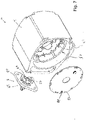
- FIG. 6 An exploded view of motor enclosure 4 and rear end bell 6 is shown in Fig. 6 .
- This view also depicts motor stator portion 80 and motor controller 82.
- Motor stator portion 80 and motor controller 82 are configured to fit into cavity 52 of motor enclosure 4.
- This view along with the view of Fig. 5 allows the skilled artisan to appreciate how motor stator portion 80 and motor controller 82 are isolated from exterior of pump 2.
- motor controller 82 operates motor 80 is by supplying current in a sequential fashion to winding pairs that surround the rotor on the stator. To accomplish this, however, requires specific modulated voltages in sequence around the coils of the stator. That said, if the voltage is not sufficient or is sequenced around the stator wire windings improperly, the rotor will not turn. Changing the frequency of the wave form of the current supplied to the motor although not being sufficient to cause the rotor to rotate, will cause the opposing pairs of wires of the stator to vibrate, not unlike piano or guitar wires. The effect of this is a status feedback signal being generated by the motor itself.
- a motor including motor stator portion 80 in motor enclosure 4 may operate at a PWM (pulse width modulation) frequency of 15,000 hertz.
- PWM pulse width modulation
- supplying current to the opposed windings in the stator in a rotational sequence at a rotational frequency of 120 hertz will cause the rotor in the motor to spin and operate the pump.
- 1,500 hertz is supplied to the opposed windings, the rotor will not rotate but will only cause the wires to vibrate producing the status feedback signal.
- ISR interrupt service routine
- motor controller 82 can send an appropriate frequency signal to one or more of the opposed windings on the stator to cause them to vibrate. That resulting status feedback signal will be perceptible by the operator to indicate there is a fault with the motor or application.
- the frequency and duration of the vibrating wires may be changed so each of the several varieties of faults can each be assigned a unique tone or tone sequence to convey to the operator the precise type of fault that is occurring with the motor.
- motor controller 82 can send an appropriate signal frequency to the motor windings for a period of time, illustratively 0.3 seconds, stop the tone for a second period of time, for example 0.2 seconds, and then repeat.
- a period of time illustratively 0.3 seconds
- stop the tone for a second period of time, for example 0.2 seconds
- repeat In an almost Morse-code-like fashion, the particular pitch of the tones and durations of same may indicate to the operator that there is a specific fault - such as a high temperature fault.
- motor controller 82 may produce a unique sequence of tones. These tones may also last for different durations and intervals that will be unique to that specific fault. By hearing this sequence of tone, the operator will know there is a low battery fault.
- tones are employed to indicate fault conditions. Distinguishing tones may be created by changing the pitch and the number of tones per fault. For example, "application/installation” and “hardware” faults may be identified by sets of tones that are distinguishable by different ordered combinations of high or low pitches.
- Tables I and II depict several potential pump, motor, or application fault conditions. The Tables are divided between “application/installation faults” and “hardware faults.” The three-tone Table lists “application/installation” faults that identify installation issues related to the pump such as priming or supply voltage, for example. The four-tone Table indicates "hardware" faults which identify conditions outside the operating parameters of the pump such as hardware and motor overtemperatures.
- an up arrow “ ⁇ ” means high tone and a down arrow “ ⁇ ” means low tone.
- the tone arrangements may be predetermined so the user will know which fault condition is indicated by listening to the tones generated by the motor inside the enclosure.
- Table I Three-Tone Faults (Application/Installation Faults) Tones Condition ⁇ Low battery voltage (auto shut-off) ⁇ High battery voltage (auto shut-off) ⁇ Locked rotor (auto shut-off) ⁇ Priming/Suction/Lift failure Table II: 4-Tone Faults (Hardware faults) Tones Condition ⁇ Hardware fault (auto shut-off) ⁇ Hardware overtemperature (auto shut-off) ⁇ Motor overtemperature (auto shut-off) ⁇ Motor overvoltage (auto shut-off) ⁇ Motor undervoltage (auto shut-off)
- a hardware overtemperature fault may include four tones composed of one low tone, one high tone, and then two succeeding low tones.
- a motor overtemperature fault may be composed of two low tones followed by two successive high tones.
- a digital audio recorder, telephone, or phone app may be used to record the sounds and send them to technical support to further diagnose and/or suggest repair options.
- Another illustrative embodiment of the present disclosure provides a switch assembly that activates and deactivates the pump motor but without any physical contact with the motor or motor controller.
- adding more openings in an explosion proof motor enclosure requires flame paths and special design considerations that add complexity and cost to the pump. Because of this, the fewer openings in the explosion-proof motor enclosure there are the simpler the pump construction and hence, the less expensive it is to manufacture.
- many pumps, particularly those dispensing fuels include a pivoting lever where rotation in one direction activates the pump, and rotation in the reverse direction deactivates the pump.
- An illustrative embodiment of the present disclosure includes an on and off switch for the pump motor that is part of the lever, but not part of the motor controller that activates the motor. No part of the switch comes into physical contact with any component of the motor through the motor enclosure. Instead, the switch includes a magnet or magnets that remain exterior of the motor enclosure but are detectible by a magnetic sensor located inside the motor enclosure. The magnets create a magnetic field that passes through the material of the motor enclosure (typically aluminum) and is readable by the sensor inside the enclosure. The sensor itself is in electric communication with the motor controller so that when a magnetic field having particular characteristics is detected by the sensor, it will send a signal to the motor controller to either activate or deactivate the motor. This is all accomplished without any part of the switch physically extending through the motor enclosure wall and contacting the components inside.
- lever assembly having a switch lever mount that may be made of steel, iron, or other like material.
- This lever mount serves as a shield for the magnet to prevent any operational interference or deliberate attempts to create an alternate magnetic field in order to activate the sensor in the motor enclosure.
- the magnets on the switch may be located on the shield but opposite the external side of same. In other words, the shield is sandwiched between the switch's lever arm and the actual magnets. This means the magnets will face the motor enclosure while the lever arm faces the exterior environment of the pump assembly.
- the senor is configured to activate the motor only upon detecting a magnetic field having particular characteristics.
- the internal sensor must detect a magnetic field having a predetermined strength and alignment in order for the sensor to initiate activating the motor.
- the shield extends laterally or transverse from the magnet(s) so the magnet(s) are uniquely positioned and oriented to produce the requisite strength and (in conjunction with movement by the lever) predetermined alignment to signal to the sensor to either activate or deactivate the pump motor. It is appreciated that in other embodiments, such magnetic switching may be used to activate other internal components within the motor enclosure.
- FIG. 7 A perspective exploded detail view of components of fluid transfer pump 2 is shown in Fig. 7 .
- motor enclosure 4 Within cavity 52 of enclosure 4 is motor stator 80 along with internal magnetic sensor 84.
- motor controller circuit board 82 is fitted into cavity 52 of motor enclosure 4 as previously discussed.
- switch mechanism assembly 8 Shown as part of switch mechanism assembly 8 is illustratively a pair of magnets 86 and 88 to create the magnetic field to be detected by internal magnetic sensor 84.
- two magnets are used so as to create a more complex magnetic field that is more difficult to mimic.
- a single magnet or other magnetic schemes may be employed.
- Such, alternatives serve the same principle as defining a magnetic field having a particular characteristic or characteristics that must be detected by magnetic sensor 84 in order to activate or deactivate any component - particularly the motor - in motor enclosure 4.
- magnets extend from shield 90. Having magnets 86 and 88 extending from shield 90 helps particularize the positioning of the magnets relative to the sensor 84 inside motor enclosure 4. This further helps ensure the magnetic field generated by the magnets to ensure only magnets in that particular location will produce the strength needed to be read by the sensor 84.
- shield 90 extends beyond the periphery of magnet casing 89, and, thus, magnets 86 and 88 to serve as shielding so either intentional or incidental magnetic fields from the outside environment will not interfere with the magnetic field intending to activate sensor 84.
- FIG. 8 A top downward looking cross-sectional view of a portion of fluid transfer pump assembly 2 is shown in Fig. 8 .
- This view depicts motor enclosure 4 with motor stator 80 shown housed within cavity 52.
- Another aspect of motor enclosure 4 is switch recess 92 configured to receive a portion of switch mechanism assembly 8.
- switch recess 92 receives magnet casing 89 that holds magnets 86 and 88.
- a counter sink 94 is illustratively formed on the periphery of switch recess 92 and is configured to receive shield 90 from switch mechanism assembly 8. It is evident from this view how magnets 86 and 88 may be contained in cavity 92 while being shrouded by shield 90. It should be appreciated from this view that cavity 92 and counter sink 94 are formed in the exterior of motor enclosure 4. They do not extend in any way into cavity 52. In other words, switch recess 92 and counter sink 94 are isolated from cavity 52.
- a pivot shaft 96 as part of switch shaft assembly 14, is disposed through bore 97 of collar 98 and extends into switch recess 92. Pivot shaft 96 may be secured in bore 97 via fastener 18. Pivot shaft 96 is also attached to magnet casing 89 in order to pivot magnets 86 and 88 (see, also, Figs. 7 and 9 ) to move same between activation and deactivation positions.
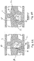
- FIGS. 9A and 9B Side cross-sectional views of motor enclosure 4 are shown in Figs. 9A and 9B . These views depict how magnet casing 89 may be pivoted by pivot shaft 96 in order to move magnets 86 and 88 to create the different characteristics of the magnetic field. Again, it is the different characteristics of the magnetic field that indicate to sensor 84 (see, also, Fig. 7 ) whether the motor should be activated or deactivated. It is appreciated from these views how the spacing between magnets 86 and 88, as well as their positioning in proximity (see, also, Figs. 7 and 8 ), create a unique magnetic field characteristic for sensor 84 to detect. Lastly, motor controller circuit board 82 is also shown in this view.
Landscapes
- Engineering & Computer Science (AREA)
- Mechanical Engineering (AREA)
- General Engineering & Computer Science (AREA)
- Power Engineering (AREA)
- Microelectronics & Electronic Packaging (AREA)
- Physics & Mathematics (AREA)
- Thermal Sciences (AREA)
- Chemical & Material Sciences (AREA)
- Combustion & Propulsion (AREA)
- Electromagnetism (AREA)
- Structures Of Non-Positive Displacement Pumps (AREA)
- Connection Of Motors, Electrical Generators, Mechanical Devices, And The Like (AREA)
- Details Of Reciprocating Pumps (AREA)
Claims (19)
- Fluidtransferpumpenanordnung (2), die Folgendes umfasst:eine Motorgehäuseanordnung (4), die einen Motorhohlraum (52) bildet, der zum Aufnehmen eines Motors bemessen ist;wobei das Motorgehäuse (4) einen Flammenweg (64) aufweist;wobei sich der Flammenweg (64) von einer inneren Verbindungsstelle (74) zu einer äußeren Verbindungsstelle (76) erstreckt;wobei die innere Verbindungsstelle (74) dem Motorhohlraum (52) und die äußere Verbindungsstelle (76) der Außenseite der Motorgehäuseanordnung (4) zugewandt ist; undeinen Kühlkörper (48), der sich im Motorhohlraum (52) der Motorgehäuseanordnung (4) befindet;wobei ein Teil des Kühlkörpers (48) an der inneren Verbindungsstelle (74) anliegt; undwobei sich kein Teil des Kühlkörpers (48) außerhalb der Motorgehäuseanordnung (4) erstreckt und/oder wobei der Kühlkörper (48) den sich von der inneren Verbindungsstelle (74) zur äußeren Verbindungsstelle (76) der Motorgehäuseanordnung (4) erstreckenden Flammenweg (64) nicht stört.
- Fluidtransferpumpenanordnung (2) nach Anspruch 1, wobei der Motorhohlraum (52) eine Motorsteuerung (82) enthält, die einen Motor (80) mit einem Rotor und einem Stator mit Strom versorgt, wobei der Stator mehrere Polpaare von Drahtwicklungen enthält, die eine sich bewegende elektromagnetische Kraft erzeugen, um den Rotor zu drehen, wobei die Motorsteuerung (82) beim Empfang von Signalen über einen Zustand des Motors (80) Strom zu mindestens einem Polpaar von Drahtwicklungen mit einer Spannung leitet, die keine Drehung des Motors (80) bewirkt, sondern bewirkt, dass das mindestens eine Polpaar von Drahtwicklungen vibriert, um ein Statusrückmeldesignal zu erzeugen.
- Fluidtransferpumpenanordnung (2) nach Anspruch 1, wobei der Motorhohlraum (52) eine Schalteranordnung (8) enthält, die Folgendes umfasst: mindestens einen Magneten (86, 88), der sich auf einer Abschirmung befindet, die sich quer zu diesem Magneten (86, 88) erstreckt, einen Schalter, der sich neben der Abschirmung gegenüber dem mindestens einen Magneten (86, 88) befindet, wobei der Schalter durch die Abschirmung hindurch mit dem Magneten (86, 88) in Eingriff gebracht werden kann, so dass sich der Magnet (86, 88) bewegt, wenn sich der Schalteraktuator bewegt, wobei der Magnet (86, 88) in einen Raum an dem Motorgehäuse (4) passt, der vom Motorhohlraum (52) in dem Motorgehäuse (4) beabstandet ist, einen Magnetfeldsensor (84), der sich innerhalb des Motorhohlraums (52) der Motorgehäuseanordnung (4) befindet und von der Außenseite des Hohlraums des Motorgehäuses (4) isoliert ist, wobei der Magnetfeldsensor (84) in elektrischer Verbindung mit einer Motorsteuerung (82) steht, um den Motor (80) für dessen Betrieb selektiv mit Strom zu versorgen, wobei der Magnetfeldsensor (84) ein Signal produziert, wenn er ein Magnetfeld mit einer durch den Magneten (86, 88) erzeugten vordefinierten Charakteristik erfasst.
- Fluidtransferpumpenanordnung (2) nach einem der vorherigen Ansprüche, wobei der Flammenweg (64) aus einem Weg besteht, der von zwei einander zugewandten Flächen der Motorgehäuseanordnung (4) gebildet wird, die sich von der inneren Verbindungsstelle (74) zur äußeren Verbindungsstelle (76) erstrecken.
- Fluidtransferpumpenanordnung (2) nach einem der vorherigen Ansprüche, wobei die Motorgehäuseanordnung (4) aus einem ersten Motorgehäuseteil (4) und einem zweiten Motorgehäuseteil (4) besteht.
- Fluidtransferpumpenanordnung (2) nach Anspruch 5 in Abhängigkeit von Anspruch 4, wobei der erste Motorgehäuseteil (4) eine erste zugewandte Fläche der beiden zugewandten Flächen aufweist und der zweite Motorgehäuseteil (4) eine zweite zugewandte Fläche der beiden zugewandten Flächen aufweist.
- Fluidtransferpumpenanordnung (2) nach Anspruch 6, wobei die innere Verbindungsstelle (74) eine erste Verbindungsfläche des ersten Motorgehäuseteils (4) und eine zweite Verbindungsfläche des zweiten Motorgehäuseteils (4) aufweist.
- Fluidtransferpumpenanordnung (2) nach Anspruch 7, wobei der Teil des Kühlkörpers (48), der an die innere Verbindungsstelle (74) angrenzt, sowohl die erste als auch die zweite Verbindungsfläche berührt, so dass Wärme im Kühlkörper (48) auf den ersten und den zweiten Motorgehäuseteil (4) übertragen wird.
- Fluidtransferpumpenanordnung (2) nach einem der vorherigen Ansprüche, wobei die innere Verbindungsstelle (74) den Motorhohlraum (52) umgibt, wobei ein Querschnitts+rofil des Motorhohlraums (52) kreisförmig, quadratisch, oval, vierseitig und polygonal ist.
- Fluidtransferpumpenanordnung (2) nach Anspruch 9, wobei der Teil des Kühlkörpers (48), der an der inneren Verbindungsstelle (74) anliegt, eine Peripherie aufweist, die sich um den Umfang des Kühlkörpers (48) erstreckt.
- Fluidtransferpumpenanordnung (2) nach Anspruch 10, wobei die Peripherie an der inneren Verbindungsstelle (74) der Motorgehäuseanordnung (4) anliegt.
- Fluidtransferpumpenanordnung (2) nach Anspruch 5 oder einem davon abhängigen Anspruch, wobei der erste und der zweite Motorgehäuseteil (4) trennbar sind.
- Fluidtransferpumpenanordnung (2) nach einem der vorherigen Ansprüche, die ferner eine wärmeerzeugende Leiterplatte (46) umfasst, die am Kühlkörper (48) angebracht werden kann und Wärme auf den Kühlkörper (48) überträgt.
- Fluidtransferpumpenanordnung (2) nach einem der vorherigen Ansprüche, wobei:die Motorgehäuseanordnung (4) durch ein Motorgehäuse (4) und eine Endglocke (6) gebildet wird, wobei das Motorgehäuse (4) und die Endglocke (6) zusammengefügt sind, um den Motorhohlraum (52) zu bilden, der zum Aufnehmen eines Motors bemessen ist;wobei das Motorgehäuse (4) einen Kragen (54) aufweist, der sich vom Motorgehäuse (4) an einer Kragenbasis erstreckt, einen Teil des Motorhohlraums (52) umgibt und an einem Kragenende distal von der Kragenbasis endet;wobei der Kragen (54) eine Kragenfläche aufweist;wobei die Endglocke (6) einen Flansch (58) aufweist, der sich von der Endglocke (6) an einer Flanschbasis erstreckt, einen Teil des Motorhohlraums (52) umgibt und an einem Flanschende distal von der Flanschbasis endet;wobei der Flansch (58) eine Flanschfläche aufweist;wobei, wenn das Motorgehäuse (4) und die Endglocke (6) zusammengefügt sind, um den Motorhohlraum (52) zu bilden, die Kragenfläche der Flanschfläche zugewandt ist, um den Flammenweg (64) zwischen der Kragen- und der Flanschfläche zu bilden;wobei, wenn das Motorgehäuse (4) und die Endglocke (6) zusammengefügt sind, um den Motorhohlraum (52) zu bilden, die Kragenbasis sich neben dem Flanschende befindet, um die Nur-Innen-Verbindungsstelle zu bilden, die dem Motorhohlraum (52) zugewandt ist, aber sich nicht außerhalb der Motorgehäuseanordnung (4) befindet;wobei, wenn das Motorgehäuse (4) und die Endglocke (6) zusammengefügt sind, um den Motorhohlraum (52) zu bilden, die Flanschbasis sich neben dem Kragenende befindet, um die Nur-Außen-Verbindungsstelle zu bilden, die sich außerhalb des Motorhohlraums (52) befindet und nicht dem Motorhohlraum (52) zugewandt ist;wobei der Kühlkörper (48) aus einer Platte besteht, die an der Nur-Innen-Verbindungsstelle der Motorgehäuseanordnung (4) positionierbar ist;wobei die Platte des Kühlkörpers (48) eine erste Fläche, eine Umfangsfläche und eine zweite Fläche aufweist, so dass sich die zweite Fläche neben der Umfangsfläche und gegenüber der ersten Fläche befindet; undeine wärmeerzeugende Leiterplatte (46), die an der Platte des Kühlkörpers (48) an einer Stelle angebracht werden kann, die aus der Gruppe bestehend aus der ersten Fläche und der zweiten Fläche ausgewählt ist;wobei ein Teil der ersten Fläche der Platte des Kühlkörpers (48) an der Nur-Innen-Verbindungsstelle an der Kragenbasis anliegt;wobei ein Teil der zweiten Fläche der Platte des Kühlkörpers (48) an der Nur-Innen-Verbindungsstelle am Flanschende anliegt; undwobei die Umfangsfläche der Platte des Kühlkörpers (48) den Flammenweg (64), der sich von der Nur-Innen-Verbindungsstelle zur Nur-Außen-Verbindungsstelle der Motorgehäuseanordnung (4) erstreckt, nicht stört.
- Fluidtransferpumpenanordnung (2) nach Anspruch 14, wobei der Motorhohlraum (52) zylindrisch ist, die Kragenfläche des Motorgehäuses (4) zylindrisch ist und die Flanschfläche der Endglocke (6) zylindrisch ist.
- Fluidtransferpumpenanordnung (2) nach Anspruch 15, wobei die Platte des Kühlkörpers (48) eine Kreisform aufweist, so dass sich die Umfangsfläche der Platte des Kühlkörpers (48) neben der zylindrischen Kragenfläche des Motorgehäuses (4) befindet.
- Fluidtransferpumpenanordnung (2) nach einem der Ansprüche 14 bis 16, wobei sich die Platte des Kühlkörpers (48) nur innerhalb der Motorgehäuseanordnung (4) befindet, wobei sich kein Teil des Kühlkörpers (48) außerhalb der Motorgehäuseanordnung (4) erstreckt und wobei keine Lüftungsöffnungen in der Motorgehäuseanordnung (4) zum Ableiten von Wärme von der wärmeerzeugenden Leiterplatte konfiguriert sind.
- Fluidtransferpumpenanordnung (2) nach einem der vorherigen Ansprüche, die ferner ein Pumpengehäuse (10) umfasst, das an der Motorgehäuseanordnung (4) angebracht ist.
- Fluidtransferpumpenanordnung (2) nach einem der vorherigen Ansprüche, wobei das Motorgehäuse (4) und die Endglocke (6) beide aus einem wärmeleitenden Material gefertigt sind.
Applications Claiming Priority (1)
| Application Number | Priority Date | Filing Date | Title |
|---|---|---|---|
| US15/958,217 US10590939B2 (en) | 2018-04-20 | 2018-04-20 | Fluid pump assembly |
Publications (3)
| Publication Number | Publication Date |
|---|---|
| EP3557061A2 EP3557061A2 (de) | 2019-10-23 |
| EP3557061A3 EP3557061A3 (de) | 2019-12-04 |
| EP3557061B1 true EP3557061B1 (de) | 2022-06-08 |
Family
ID=66218008
Family Applications (1)
| Application Number | Title | Priority Date | Filing Date |
|---|---|---|---|
| EP19169961.0A Active EP3557061B1 (de) | 2018-04-20 | 2019-04-17 | Flüssigkeitspumpenanordnung |
Country Status (5)
| Country | Link |
|---|---|
| US (3) | US10590939B2 (de) |
| EP (1) | EP3557061B1 (de) |
| CN (3) | CN118944342A (de) |
| CA (1) | CA3040400A1 (de) |
| MX (3) | MX2019004509A (de) |
Families Citing this family (7)
| Publication number | Priority date | Publication date | Assignee | Title |
|---|---|---|---|---|
| US10590939B2 (en) * | 2018-04-20 | 2020-03-17 | Tuthill Corporation | Fluid pump assembly |
| US11852152B2 (en) * | 2019-10-07 | 2023-12-26 | The Gorman-Rupp Company | Pin vent assembly |
| DE102020106796A1 (de) * | 2020-03-12 | 2021-09-16 | Schwäbische Hüttenwerke Automotive GmbH | Pumpeneinsatz und Pumpenanordnung mit einem solchen Pumpeneinsatz |
| DE102021102395A1 (de) * | 2021-02-02 | 2022-08-04 | Fte Automotive Gmbh | Flüssigkeitspumpe und Verfahren zur Montage einer Flüssigkeitspumpe |
| US12431699B2 (en) * | 2022-05-27 | 2025-09-30 | Schaeffler Technologies AG & Co. KG | Cable gland |
| WO2024173396A1 (en) * | 2023-02-13 | 2024-08-22 | The Gorman-Rupp Company | Explosion proof motor, pump system, and method |
| CN116857201A (zh) * | 2023-07-11 | 2023-10-10 | 广州安捷制造有限公司 | 泳池水泵 |
Family Cites Families (18)
| Publication number | Priority date | Publication date | Assignee | Title |
|---|---|---|---|---|
| US4013383A (en) * | 1973-12-03 | 1977-03-22 | Rule Industries, Inc. | Vertical shaft impeller pump apparatus |
| DE3815427C3 (de) | 1987-05-08 | 1995-08-31 | Lutz Pumpen Gmbh & Co Kg | Elektromotor, insbesondere Antriebsmotor für eine Faß- oder Behälterpumpe |
| EP0742872B1 (de) * | 1994-11-07 | 1999-10-06 | Hobourn Automotive Limited | Einheit mit drehkolbenpumpe und motor |
| DE29502004U1 (de) * | 1995-02-08 | 1996-06-05 | Hanning & Kahl GmbH & Co., 33813 Oerlinghausen | Explosionsgeschützte elektrische Maschine |
| DE19527879A1 (de) | 1995-07-29 | 1997-01-30 | Lutz Pumpen Gmbh & Co Kg | Elektromotor, insbesondere Antriebsmotor für eine Faß- oder Behälterpumpe |
| DE19624145A1 (de) | 1996-06-18 | 1998-01-08 | Wilo Gmbh | Elektromotor |
| US5930852A (en) * | 1997-03-21 | 1999-08-03 | Aqua-Flo, Incorporated | Heat exchanging pump motor for usage within a recirculating water system |
| DE19956380C1 (de) * | 1999-11-24 | 2001-01-04 | Bosch Gmbh Robert | Flüssigkeitspumpe mit einem Motorgehäuse und Verfahren zur Herstellung eines Motorgehäuses |
| JP4034077B2 (ja) * | 2002-01-30 | 2008-01-16 | カルソニックカンセイ株式会社 | キャンドポンプ |
| US7036892B2 (en) * | 2003-05-28 | 2006-05-02 | Aisin Seiki Kabushiki Kaisha | Electric powered pump |
| RU2008102243A (ru) * | 2005-06-22 | 2009-07-27 | Ай Ти Ти Мэньюфэкчуринг Энтерпрайзиз Инк. (Us) | Устройство для вращающегося сальникового уплотнения |
| KR101489747B1 (ko) | 2010-08-25 | 2015-02-04 | 마그나 파워트레인 인크. | 고정자 냉각을 갖는 전기 물 펌프 |
| CN202231561U (zh) * | 2011-09-19 | 2012-05-23 | 浙江凯利达防爆机电有限公司 | 一种散热防爆电机 |
| AU2014209656B2 (en) | 2013-01-28 | 2016-06-16 | Dixon Pumps Inc. | System, apparatus, and method for controlling a motor |
| GB201307257D0 (en) * | 2013-04-22 | 2013-05-29 | Flowork Systems Ii Llc | Conrollable variable flow coolant pump and flow management mechanism |
| GB2517457B (en) * | 2013-08-21 | 2016-06-08 | Pyroban Ltd | Enclosure for electric motor |
| CN105896824A (zh) * | 2016-06-16 | 2016-08-24 | 日本电产凯宇汽车电器(江苏)有限公司 | 一种具有水冷却和水润滑功能的电动水泵 |
| US10590939B2 (en) * | 2018-04-20 | 2020-03-17 | Tuthill Corporation | Fluid pump assembly |
-
2018
- 2018-04-20 US US15/958,217 patent/US10590939B2/en active Active
-
2019
- 2019-04-16 MX MX2019004509A patent/MX2019004509A/es unknown
- 2019-04-16 MX MX2023008497A patent/MX2023008497A/es unknown
- 2019-04-16 MX MX2023008496A patent/MX2023008496A/es unknown
- 2019-04-16 CA CA3040400A patent/CA3040400A1/en active Pending
- 2019-04-17 EP EP19169961.0A patent/EP3557061B1/de active Active
- 2019-04-19 CN CN202411050186.1A patent/CN118944342A/zh active Pending
- 2019-04-19 CN CN201910319951.8A patent/CN110391712B/zh active Active
- 2019-04-19 CN CN202411050185.7A patent/CN118944341A/zh active Pending
-
2020
- 2020-03-16 US US16/819,356 patent/US11346353B2/en active Active
-
2022
- 2022-05-30 US US17/827,864 patent/US12066028B2/en active Active
Also Published As
| Publication number | Publication date |
|---|---|
| CN110391712B (zh) | 2024-10-01 |
| CN118944342A (zh) | 2024-11-12 |
| CN110391712A (zh) | 2019-10-29 |
| EP3557061A3 (de) | 2019-12-04 |
| MX2019004509A (es) | 2019-11-21 |
| EP3557061A2 (de) | 2019-10-23 |
| US20220299037A1 (en) | 2022-09-22 |
| US11346353B2 (en) | 2022-05-31 |
| US10590939B2 (en) | 2020-03-17 |
| CN118944341A (zh) | 2024-11-12 |
| US12066028B2 (en) | 2024-08-20 |
| MX2023008496A (es) | 2023-07-26 |
| MX2023008497A (es) | 2023-07-26 |
| CA3040400A1 (en) | 2019-10-20 |
| US20200217323A1 (en) | 2020-07-09 |
| US20190323512A1 (en) | 2019-10-24 |
Similar Documents
| Publication | Publication Date | Title |
|---|---|---|
| EP3557061B1 (de) | Flüssigkeitspumpenanordnung | |
| CN102713301B (zh) | 泵机组 | |
| US20030048084A1 (en) | Low profile motor | |
| CN111164866B (zh) | 冷却风扇 | |
| KR20120119916A (ko) | 터보 분자 펌프 장치 | |
| CN107690724B (zh) | 电池组用多冷却风扇控制系统 | |
| EP2936658A1 (de) | Elektrische maschine | |
| JP7539560B2 (ja) | 電動オイルポンプ | |
| JP6251920B2 (ja) | 電動モータおよび電動ポンプ | |
| JP2012092742A (ja) | 電動ポンプ | |
| JP4661278B2 (ja) | ターボ分子ポンプ | |
| EP3835921A1 (de) | Wärmeableitungsanordnung und elektronische vorrichtung | |
| JP2014161209A (ja) | 電動モータ及び電動ポンプ | |
| US6296458B1 (en) | Electric fuel pump | |
| TWI287345B (en) | Motor with a rotation-fan and air cooling device | |
| JP2001193683A (ja) | 流体ポンプ装置 | |
| KR101953787B1 (ko) | 전동식 워터펌프 및 이의 제작방법 | |
| JP3172822U (ja) | 真空ポンプ | |
| JP2020051358A (ja) | 制御盤および給水装置 | |
| JP2010048169A (ja) | ターボ分子ポンプ | |
| CN114710933B (zh) | 一种电气机柜散热装置及自动报警方法 | |
| KR20210007136A (ko) | 모터 | |
| CN220204205U (zh) | 一种电子泵 | |
| US20220209632A1 (en) | Motor and Electric Device Comprising Such Motor | |
| JP2021505111A (ja) | 一体型モータ電子機器 |
Legal Events
| Date | Code | Title | Description |
|---|---|---|---|
| PUAI | Public reference made under article 153(3) epc to a published international application that has entered the european phase |
Free format text: ORIGINAL CODE: 0009012 |
|
| STAA | Information on the status of an ep patent application or granted ep patent |
Free format text: STATUS: THE APPLICATION HAS BEEN PUBLISHED |
|
| AK | Designated contracting states |
Kind code of ref document: A2 Designated state(s): AL AT BE BG CH CY CZ DE DK EE ES FI FR GB GR HR HU IE IS IT LI LT LU LV MC MK MT NL NO PL PT RO RS SE SI SK SM TR |
|
| AX | Request for extension of the european patent |
Extension state: BA ME |
|
| PUAL | Search report despatched |
Free format text: ORIGINAL CODE: 0009013 |
|
| AK | Designated contracting states |
Kind code of ref document: A3 Designated state(s): AL AT BE BG CH CY CZ DE DK EE ES FI FR GB GR HR HU IE IS IT LI LT LU LV MC MK MT NL NO PL PT RO RS SE SI SK SM TR |
|
| AX | Request for extension of the european patent |
Extension state: BA ME |
|
| RIC1 | Information provided on ipc code assigned before grant |
Ipc: H02K 5/04 20060101ALI20191031BHEP Ipc: F04B 53/16 20060101AFI20191031BHEP Ipc: F02M 37/00 20060101ALI20191031BHEP Ipc: F04C 15/00 20060101ALI20191031BHEP Ipc: F04D 29/40 20060101ALI20191031BHEP Ipc: H02K 5/136 20060101ALI20191031BHEP |
|
| STAA | Information on the status of an ep patent application or granted ep patent |
Free format text: STATUS: REQUEST FOR EXAMINATION WAS MADE |
|
| 17P | Request for examination filed |
Effective date: 20200602 |
|
| RBV | Designated contracting states (corrected) |
Designated state(s): AL AT BE BG CH CY CZ DE DK EE ES FI FR GB GR HR HU IE IS IT LI LT LU LV MC MK MT NL NO PL PT RO RS SE SI SK SM TR |
|
| STAA | Information on the status of an ep patent application or granted ep patent |
Free format text: STATUS: EXAMINATION IS IN PROGRESS |
|
| 17Q | First examination report despatched |
Effective date: 20200917 |
|
| RIC1 | Information provided on ipc code assigned before grant |
Ipc: H02K 11/33 20160101ALI20210810BHEP Ipc: H02K 11/215 20160101ALI20210810BHEP Ipc: H02K 7/14 20060101ALI20210810BHEP Ipc: H02K 5/136 20060101ALI20210810BHEP Ipc: F02M 37/14 20060101ALI20210810BHEP Ipc: F02M 37/10 20060101ALI20210810BHEP Ipc: F02M 37/00 20060101ALI20210810BHEP Ipc: F04D 29/42 20060101ALI20210810BHEP Ipc: F04D 29/40 20060101ALI20210810BHEP Ipc: F04D 13/06 20060101ALI20210810BHEP Ipc: F04C 15/00 20060101ALI20210810BHEP Ipc: F04C 14/28 20060101ALI20210810BHEP Ipc: F04C 2/344 20060101ALI20210810BHEP Ipc: F04B 53/16 20060101AFI20210810BHEP |
|
| GRAP | Despatch of communication of intention to grant a patent |
Free format text: ORIGINAL CODE: EPIDOSNIGR1 |
|
| STAA | Information on the status of an ep patent application or granted ep patent |
Free format text: STATUS: GRANT OF PATENT IS INTENDED |
|
| INTG | Intention to grant announced |
Effective date: 20211006 |
|
| GRAJ | Information related to disapproval of communication of intention to grant by the applicant or resumption of examination proceedings by the epo deleted |
Free format text: ORIGINAL CODE: EPIDOSDIGR1 |
|
| STAA | Information on the status of an ep patent application or granted ep patent |
Free format text: STATUS: EXAMINATION IS IN PROGRESS |
|
| GRAP | Despatch of communication of intention to grant a patent |
Free format text: ORIGINAL CODE: EPIDOSNIGR1 |
|
| STAA | Information on the status of an ep patent application or granted ep patent |
Free format text: STATUS: GRANT OF PATENT IS INTENDED |
|
| INTC | Intention to grant announced (deleted) | ||
| INTG | Intention to grant announced |
Effective date: 20220204 |
|
| GRAS | Grant fee paid |
Free format text: ORIGINAL CODE: EPIDOSNIGR3 |
|
| GRAA | (expected) grant |
Free format text: ORIGINAL CODE: 0009210 |
|
| STAA | Information on the status of an ep patent application or granted ep patent |
Free format text: STATUS: THE PATENT HAS BEEN GRANTED |
|
| AK | Designated contracting states |
Kind code of ref document: B1 Designated state(s): AL AT BE BG CH CY CZ DE DK EE ES FI FR GB GR HR HU IE IS IT LI LT LU LV MC MK MT NL NO PL PT RO RS SE SI SK SM TR |
|
| REG | Reference to a national code |
Ref country code: AT Ref legal event code: REF Ref document number: 1497099 Country of ref document: AT Kind code of ref document: T Effective date: 20220615 Ref country code: CH Ref legal event code: EP |
|
| REG | Reference to a national code |
Ref country code: DE Ref legal event code: R096 Ref document number: 602019015578 Country of ref document: DE |
|
| REG | Reference to a national code |
Ref country code: IE Ref legal event code: FG4D |
|
| RAP2 | Party data changed (patent owner data changed or rights of a patent transferred) |
Owner name: THE GORMAN-RUPP COMPANY |
|
| REG | Reference to a national code |
Ref country code: LT Ref legal event code: MG9D |
|
| REG | Reference to a national code |
Ref country code: NL Ref legal event code: MP Effective date: 20220608 |
|
| PG25 | Lapsed in a contracting state [announced via postgrant information from national office to epo] |
Ref country code: SE Free format text: LAPSE BECAUSE OF FAILURE TO SUBMIT A TRANSLATION OF THE DESCRIPTION OR TO PAY THE FEE WITHIN THE PRESCRIBED TIME-LIMIT Effective date: 20220608 Ref country code: NO Free format text: LAPSE BECAUSE OF FAILURE TO SUBMIT A TRANSLATION OF THE DESCRIPTION OR TO PAY THE FEE WITHIN THE PRESCRIBED TIME-LIMIT Effective date: 20220908 Ref country code: LT Free format text: LAPSE BECAUSE OF FAILURE TO SUBMIT A TRANSLATION OF THE DESCRIPTION OR TO PAY THE FEE WITHIN THE PRESCRIBED TIME-LIMIT Effective date: 20220608 Ref country code: HR Free format text: LAPSE BECAUSE OF FAILURE TO SUBMIT A TRANSLATION OF THE DESCRIPTION OR TO PAY THE FEE WITHIN THE PRESCRIBED TIME-LIMIT Effective date: 20220608 Ref country code: GR Free format text: LAPSE BECAUSE OF FAILURE TO SUBMIT A TRANSLATION OF THE DESCRIPTION OR TO PAY THE FEE WITHIN THE PRESCRIBED TIME-LIMIT Effective date: 20220909 Ref country code: FI Free format text: LAPSE BECAUSE OF FAILURE TO SUBMIT A TRANSLATION OF THE DESCRIPTION OR TO PAY THE FEE WITHIN THE PRESCRIBED TIME-LIMIT Effective date: 20220608 Ref country code: ES Free format text: LAPSE BECAUSE OF FAILURE TO SUBMIT A TRANSLATION OF THE DESCRIPTION OR TO PAY THE FEE WITHIN THE PRESCRIBED TIME-LIMIT Effective date: 20220608 Ref country code: BG Free format text: LAPSE BECAUSE OF FAILURE TO SUBMIT A TRANSLATION OF THE DESCRIPTION OR TO PAY THE FEE WITHIN THE PRESCRIBED TIME-LIMIT Effective date: 20220908 |
|
| REG | Reference to a national code |
Ref country code: AT Ref legal event code: MK05 Ref document number: 1497099 Country of ref document: AT Kind code of ref document: T Effective date: 20220608 |
|
| PG25 | Lapsed in a contracting state [announced via postgrant information from national office to epo] |
Ref country code: RS Free format text: LAPSE BECAUSE OF FAILURE TO SUBMIT A TRANSLATION OF THE DESCRIPTION OR TO PAY THE FEE WITHIN THE PRESCRIBED TIME-LIMIT Effective date: 20220608 Ref country code: LV Free format text: LAPSE BECAUSE OF FAILURE TO SUBMIT A TRANSLATION OF THE DESCRIPTION OR TO PAY THE FEE WITHIN THE PRESCRIBED TIME-LIMIT Effective date: 20220608 |
|
| REG | Reference to a national code |
Ref country code: DE Ref legal event code: R081 Ref document number: 602019015578 Country of ref document: DE Owner name: THE GORMAN- RUPP COMPANY, MANSFIELD, US Free format text: FORMER OWNER: TUTHILL CORP., FORT WAYNE, IN, US |
|
| PG25 | Lapsed in a contracting state [announced via postgrant information from national office to epo] |
Ref country code: NL Free format text: LAPSE BECAUSE OF FAILURE TO SUBMIT A TRANSLATION OF THE DESCRIPTION OR TO PAY THE FEE WITHIN THE PRESCRIBED TIME-LIMIT Effective date: 20220608 |
|
| PG25 | Lapsed in a contracting state [announced via postgrant information from national office to epo] |
Ref country code: SM Free format text: LAPSE BECAUSE OF FAILURE TO SUBMIT A TRANSLATION OF THE DESCRIPTION OR TO PAY THE FEE WITHIN THE PRESCRIBED TIME-LIMIT Effective date: 20220608 Ref country code: SK Free format text: LAPSE BECAUSE OF FAILURE TO SUBMIT A TRANSLATION OF THE DESCRIPTION OR TO PAY THE FEE WITHIN THE PRESCRIBED TIME-LIMIT Effective date: 20220608 Ref country code: RO Free format text: LAPSE BECAUSE OF FAILURE TO SUBMIT A TRANSLATION OF THE DESCRIPTION OR TO PAY THE FEE WITHIN THE PRESCRIBED TIME-LIMIT Effective date: 20220608 Ref country code: PT Free format text: LAPSE BECAUSE OF FAILURE TO SUBMIT A TRANSLATION OF THE DESCRIPTION OR TO PAY THE FEE WITHIN THE PRESCRIBED TIME-LIMIT Effective date: 20221010 Ref country code: EE Free format text: LAPSE BECAUSE OF FAILURE TO SUBMIT A TRANSLATION OF THE DESCRIPTION OR TO PAY THE FEE WITHIN THE PRESCRIBED TIME-LIMIT Effective date: 20220608 Ref country code: CZ Free format text: LAPSE BECAUSE OF FAILURE TO SUBMIT A TRANSLATION OF THE DESCRIPTION OR TO PAY THE FEE WITHIN THE PRESCRIBED TIME-LIMIT Effective date: 20220608 Ref country code: AT Free format text: LAPSE BECAUSE OF FAILURE TO SUBMIT A TRANSLATION OF THE DESCRIPTION OR TO PAY THE FEE WITHIN THE PRESCRIBED TIME-LIMIT Effective date: 20220608 |
|
| PG25 | Lapsed in a contracting state [announced via postgrant information from national office to epo] |
Ref country code: PL Free format text: LAPSE BECAUSE OF FAILURE TO SUBMIT A TRANSLATION OF THE DESCRIPTION OR TO PAY THE FEE WITHIN THE PRESCRIBED TIME-LIMIT Effective date: 20220608 Ref country code: IS Free format text: LAPSE BECAUSE OF FAILURE TO SUBMIT A TRANSLATION OF THE DESCRIPTION OR TO PAY THE FEE WITHIN THE PRESCRIBED TIME-LIMIT Effective date: 20221008 |
|
| REG | Reference to a national code |
Ref country code: DE Ref legal event code: R097 Ref document number: 602019015578 Country of ref document: DE |
|
| PG25 | Lapsed in a contracting state [announced via postgrant information from national office to epo] |
Ref country code: AL Free format text: LAPSE BECAUSE OF FAILURE TO SUBMIT A TRANSLATION OF THE DESCRIPTION OR TO PAY THE FEE WITHIN THE PRESCRIBED TIME-LIMIT Effective date: 20220608 |
|
| PLBE | No opposition filed within time limit |
Free format text: ORIGINAL CODE: 0009261 |
|
| STAA | Information on the status of an ep patent application or granted ep patent |
Free format text: STATUS: NO OPPOSITION FILED WITHIN TIME LIMIT |
|
| PG25 | Lapsed in a contracting state [announced via postgrant information from national office to epo] |
Ref country code: DK Free format text: LAPSE BECAUSE OF FAILURE TO SUBMIT A TRANSLATION OF THE DESCRIPTION OR TO PAY THE FEE WITHIN THE PRESCRIBED TIME-LIMIT Effective date: 20220608 |
|
| 26N | No opposition filed |
Effective date: 20230310 |
|
| PG25 | Lapsed in a contracting state [announced via postgrant information from national office to epo] |
Ref country code: SI Free format text: LAPSE BECAUSE OF FAILURE TO SUBMIT A TRANSLATION OF THE DESCRIPTION OR TO PAY THE FEE WITHIN THE PRESCRIBED TIME-LIMIT Effective date: 20220608 |
|
| P01 | Opt-out of the competence of the unified patent court (upc) registered |
Effective date: 20230626 |
|
| REG | Reference to a national code |
Ref country code: CH Ref legal event code: PL |
|
| PG25 | Lapsed in a contracting state [announced via postgrant information from national office to epo] |
Ref country code: LU Free format text: LAPSE BECAUSE OF NON-PAYMENT OF DUE FEES Effective date: 20230417 |
|
| REG | Reference to a national code |
Ref country code: BE Ref legal event code: MM Effective date: 20230430 |
|
| PG25 | Lapsed in a contracting state [announced via postgrant information from national office to epo] |
Ref country code: MC Free format text: LAPSE BECAUSE OF FAILURE TO SUBMIT A TRANSLATION OF THE DESCRIPTION OR TO PAY THE FEE WITHIN THE PRESCRIBED TIME-LIMIT Effective date: 20220608 |
|
| PG25 | Lapsed in a contracting state [announced via postgrant information from national office to epo] |
Ref country code: MC Free format text: LAPSE BECAUSE OF FAILURE TO SUBMIT A TRANSLATION OF THE DESCRIPTION OR TO PAY THE FEE WITHIN THE PRESCRIBED TIME-LIMIT Effective date: 20220608 Ref country code: LI Free format text: LAPSE BECAUSE OF NON-PAYMENT OF DUE FEES Effective date: 20230430 Ref country code: FR Free format text: LAPSE BECAUSE OF NON-PAYMENT OF DUE FEES Effective date: 20230430 Ref country code: CH Free format text: LAPSE BECAUSE OF NON-PAYMENT OF DUE FEES Effective date: 20230430 |
|
| REG | Reference to a national code |
Ref country code: IE Ref legal event code: MM4A |
|
| PG25 | Lapsed in a contracting state [announced via postgrant information from national office to epo] |
Ref country code: BE Free format text: LAPSE BECAUSE OF NON-PAYMENT OF DUE FEES Effective date: 20230430 |
|
| PG25 | Lapsed in a contracting state [announced via postgrant information from national office to epo] |
Ref country code: IE Free format text: LAPSE BECAUSE OF NON-PAYMENT OF DUE FEES Effective date: 20230417 |
|
| PG25 | Lapsed in a contracting state [announced via postgrant information from national office to epo] |
Ref country code: IE Free format text: LAPSE BECAUSE OF NON-PAYMENT OF DUE FEES Effective date: 20230417 |
|
| PG25 | Lapsed in a contracting state [announced via postgrant information from national office to epo] |
Ref country code: BG Free format text: LAPSE BECAUSE OF FAILURE TO SUBMIT A TRANSLATION OF THE DESCRIPTION OR TO PAY THE FEE WITHIN THE PRESCRIBED TIME-LIMIT Effective date: 20220608 |
|
| PG25 | Lapsed in a contracting state [announced via postgrant information from national office to epo] |
Ref country code: BG Free format text: LAPSE BECAUSE OF FAILURE TO SUBMIT A TRANSLATION OF THE DESCRIPTION OR TO PAY THE FEE WITHIN THE PRESCRIBED TIME-LIMIT Effective date: 20220608 |
|
| PGFP | Annual fee paid to national office [announced via postgrant information from national office to epo] |
Ref country code: DE Payment date: 20250429 Year of fee payment: 7 |
|
| PGFP | Annual fee paid to national office [announced via postgrant information from national office to epo] |
Ref country code: GB Payment date: 20250428 Year of fee payment: 7 |
|
| PGFP | Annual fee paid to national office [announced via postgrant information from national office to epo] |
Ref country code: IT Payment date: 20250422 Year of fee payment: 7 |
|
| PG25 | Lapsed in a contracting state [announced via postgrant information from national office to epo] |
Ref country code: CY Free format text: LAPSE BECAUSE OF FAILURE TO SUBMIT A TRANSLATION OF THE DESCRIPTION OR TO PAY THE FEE WITHIN THE PRESCRIBED TIME-LIMIT; INVALID AB INITIO Effective date: 20190417 |
|
| PG25 | Lapsed in a contracting state [announced via postgrant information from national office to epo] |
Ref country code: HU Free format text: LAPSE BECAUSE OF FAILURE TO SUBMIT A TRANSLATION OF THE DESCRIPTION OR TO PAY THE FEE WITHIN THE PRESCRIBED TIME-LIMIT; INVALID AB INITIO Effective date: 20190417 |
|
| PG25 | Lapsed in a contracting state [announced via postgrant information from national office to epo] |
Ref country code: TR Free format text: LAPSE BECAUSE OF FAILURE TO SUBMIT A TRANSLATION OF THE DESCRIPTION OR TO PAY THE FEE WITHIN THE PRESCRIBED TIME-LIMIT Effective date: 20220608 |