EP3557061A2 - Fluid pump assembly - Google Patents
Fluid pump assembly Download PDFInfo
- Publication number
- EP3557061A2 EP3557061A2 EP19169961.0A EP19169961A EP3557061A2 EP 3557061 A2 EP3557061 A2 EP 3557061A2 EP 19169961 A EP19169961 A EP 19169961A EP 3557061 A2 EP3557061 A2 EP 3557061A2
- Authority
- EP
- European Patent Office
- Prior art keywords
- motor
- enclosure
- assembly
- heat sink
- joint
- Prior art date
- Legal status (The legal status is an assumption and is not a legal conclusion. Google has not performed a legal analysis and makes no representation as to the accuracy of the status listed.)
- Granted
Links
- 239000012530 fluid Substances 0.000 title claims abstract description 111
- 238000012546 transfer Methods 0.000 claims abstract description 113
- 238000004804 winding Methods 0.000 claims abstract description 47
- 230000037361 pathway Effects 0.000 claims description 8
- 238000004891 communication Methods 0.000 claims description 7
- 239000004020 conductor Substances 0.000 claims description 5
- 230000001419 dependent effect Effects 0.000 claims description 3
- 230000004913 activation Effects 0.000 abstract description 3
- 230000009849 deactivation Effects 0.000 abstract description 3
- 238000006243 chemical reaction Methods 0.000 description 13
- 230000007246 mechanism Effects 0.000 description 10
- 238000004880 explosion Methods 0.000 description 8
- 238000009434 installation Methods 0.000 description 5
- 239000000463 material Substances 0.000 description 5
- 238000000034 method Methods 0.000 description 5
- 238000013022 venting Methods 0.000 description 5
- 238000002485 combustion reaction Methods 0.000 description 4
- 229910052751 metal Inorganic materials 0.000 description 4
- 239000002184 metal Substances 0.000 description 4
- 230000037452 priming Effects 0.000 description 4
- 231100001261 hazardous Toxicity 0.000 description 3
- 239000011295 pitch Substances 0.000 description 3
- 230000002441 reversible effect Effects 0.000 description 3
- XEEYBQQBJWHFJM-UHFFFAOYSA-N Iron Chemical compound [Fe] XEEYBQQBJWHFJM-UHFFFAOYSA-N 0.000 description 2
- 108010076504 Protein Sorting Signals Proteins 0.000 description 2
- 230000000712 assembly Effects 0.000 description 2
- 238000000429 assembly Methods 0.000 description 2
- 238000010276 construction Methods 0.000 description 2
- 239000002360 explosive Substances 0.000 description 2
- 239000000446 fuel Substances 0.000 description 2
- 230000017525 heat dissipation Effects 0.000 description 2
- 230000001965 increasing effect Effects 0.000 description 2
- 238000012986 modification Methods 0.000 description 2
- 230000004048 modification Effects 0.000 description 2
- 230000001902 propagating effect Effects 0.000 description 2
- 238000003860 storage Methods 0.000 description 2
- 229910000831 Steel Inorganic materials 0.000 description 1
- 230000002159 abnormal effect Effects 0.000 description 1
- 230000003213 activating effect Effects 0.000 description 1
- 229910052782 aluminium Inorganic materials 0.000 description 1
- XAGFODPZIPBFFR-UHFFFAOYSA-N aluminium Chemical compound [Al] XAGFODPZIPBFFR-UHFFFAOYSA-N 0.000 description 1
- 230000001010 compromised effect Effects 0.000 description 1
- 230000003247 decreasing effect Effects 0.000 description 1
- 238000013461 design Methods 0.000 description 1
- 238000009826 distribution Methods 0.000 description 1
- 230000000694 effects Effects 0.000 description 1
- 238000005516 engineering process Methods 0.000 description 1
- 230000002708 enhancing effect Effects 0.000 description 1
- 230000003090 exacerbative effect Effects 0.000 description 1
- 230000006870 function Effects 0.000 description 1
- 239000000383 hazardous chemical Substances 0.000 description 1
- 230000002452 interceptive effect Effects 0.000 description 1
- 229910052742 iron Inorganic materials 0.000 description 1
- 230000000670 limiting effect Effects 0.000 description 1
- 238000004519 manufacturing process Methods 0.000 description 1
- 230000003278 mimic effect Effects 0.000 description 1
- 230000000116 mitigating effect Effects 0.000 description 1
- 230000008569 process Effects 0.000 description 1
- 230000008439 repair process Effects 0.000 description 1
- 230000005236 sound signal Effects 0.000 description 1
- 239000010959 steel Substances 0.000 description 1
Images


Classifications
-
- F—MECHANICAL ENGINEERING; LIGHTING; HEATING; WEAPONS; BLASTING
- F04—POSITIVE - DISPLACEMENT MACHINES FOR LIQUIDS; PUMPS FOR LIQUIDS OR ELASTIC FLUIDS
- F04D—NON-POSITIVE-DISPLACEMENT PUMPS
- F04D25/00—Pumping installations or systems
- F04D25/02—Units comprising pumps and their driving means
- F04D25/08—Units comprising pumps and their driving means the working fluid being air, e.g. for ventilation
- F04D25/082—Units comprising pumps and their driving means the working fluid being air, e.g. for ventilation the unit having provision for cooling the motor
-
- F—MECHANICAL ENGINEERING; LIGHTING; HEATING; WEAPONS; BLASTING
- F04—POSITIVE - DISPLACEMENT MACHINES FOR LIQUIDS; PUMPS FOR LIQUIDS OR ELASTIC FLUIDS
- F04B—POSITIVE-DISPLACEMENT MACHINES FOR LIQUIDS; PUMPS
- F04B53/00—Component parts, details or accessories not provided for in, or of interest apart from, groups F04B1/00 - F04B23/00 or F04B39/00 - F04B47/00
- F04B53/16—Casings; Cylinders; Cylinder liners or heads; Fluid connections
-
- F—MECHANICAL ENGINEERING; LIGHTING; HEATING; WEAPONS; BLASTING
- F02—COMBUSTION ENGINES; HOT-GAS OR COMBUSTION-PRODUCT ENGINE PLANTS
- F02M—SUPPLYING COMBUSTION ENGINES IN GENERAL WITH COMBUSTIBLE MIXTURES OR CONSTITUENTS THEREOF
- F02M37/00—Apparatus or systems for feeding liquid fuel from storage containers to carburettors or fuel-injection apparatus; Arrangements for purifying liquid fuel specially adapted for, or arranged on, internal-combustion engines
- F02M37/04—Feeding by means of driven pumps
- F02M37/08—Feeding by means of driven pumps electrically driven
- F02M37/10—Feeding by means of driven pumps electrically driven submerged in fuel, e.g. in reservoir
-
- F—MECHANICAL ENGINEERING; LIGHTING; HEATING; WEAPONS; BLASTING
- F04—POSITIVE - DISPLACEMENT MACHINES FOR LIQUIDS; PUMPS FOR LIQUIDS OR ELASTIC FLUIDS
- F04C—ROTARY-PISTON, OR OSCILLATING-PISTON, POSITIVE-DISPLACEMENT MACHINES FOR LIQUIDS; ROTARY-PISTON, OR OSCILLATING-PISTON, POSITIVE-DISPLACEMENT PUMPS
- F04C14/00—Control of, monitoring of, or safety arrangements for, machines, pumps or pumping installations
- F04C14/28—Safety arrangements; Monitoring
-
- F—MECHANICAL ENGINEERING; LIGHTING; HEATING; WEAPONS; BLASTING
- F04—POSITIVE - DISPLACEMENT MACHINES FOR LIQUIDS; PUMPS FOR LIQUIDS OR ELASTIC FLUIDS
- F04C—ROTARY-PISTON, OR OSCILLATING-PISTON, POSITIVE-DISPLACEMENT MACHINES FOR LIQUIDS; ROTARY-PISTON, OR OSCILLATING-PISTON, POSITIVE-DISPLACEMENT PUMPS
- F04C15/00—Component parts, details or accessories of machines, pumps or pumping installations, not provided for in groups F04C2/00 - F04C14/00
- F04C15/0057—Driving elements, brakes, couplings, transmission specially adapted for machines or pumps
- F04C15/008—Prime movers
-
- F—MECHANICAL ENGINEERING; LIGHTING; HEATING; WEAPONS; BLASTING
- F04—POSITIVE - DISPLACEMENT MACHINES FOR LIQUIDS; PUMPS FOR LIQUIDS OR ELASTIC FLUIDS
- F04D—NON-POSITIVE-DISPLACEMENT PUMPS
- F04D13/00—Pumping installations or systems
- F04D13/02—Units comprising pumps and their driving means
- F04D13/06—Units comprising pumps and their driving means the pump being electrically driven
- F04D13/0646—Units comprising pumps and their driving means the pump being electrically driven the hollow pump or motor shaft being the conduit for the working fluid
-
- F—MECHANICAL ENGINEERING; LIGHTING; HEATING; WEAPONS; BLASTING
- F04—POSITIVE - DISPLACEMENT MACHINES FOR LIQUIDS; PUMPS FOR LIQUIDS OR ELASTIC FLUIDS
- F04D—NON-POSITIVE-DISPLACEMENT PUMPS
- F04D29/00—Details, component parts, or accessories
- F04D29/40—Casings; Connections of working fluid
- F04D29/42—Casings; Connections of working fluid for radial or helico-centrifugal pumps
- F04D29/426—Casings; Connections of working fluid for radial or helico-centrifugal pumps especially adapted for liquid pumps
-
- F—MECHANICAL ENGINEERING; LIGHTING; HEATING; WEAPONS; BLASTING
- F04—POSITIVE - DISPLACEMENT MACHINES FOR LIQUIDS; PUMPS FOR LIQUIDS OR ELASTIC FLUIDS
- F04D—NON-POSITIVE-DISPLACEMENT PUMPS
- F04D29/00—Details, component parts, or accessories
- F04D29/58—Cooling; Heating; Diminishing heat transfer
- F04D29/5806—Cooling the drive system
-
- F—MECHANICAL ENGINEERING; LIGHTING; HEATING; WEAPONS; BLASTING
- F04—POSITIVE - DISPLACEMENT MACHINES FOR LIQUIDS; PUMPS FOR LIQUIDS OR ELASTIC FLUIDS
- F04D—NON-POSITIVE-DISPLACEMENT PUMPS
- F04D29/00—Details, component parts, or accessories
- F04D29/58—Cooling; Heating; Diminishing heat transfer
- F04D29/582—Cooling; Heating; Diminishing heat transfer specially adapted for elastic fluid pumps
- F04D29/584—Cooling; Heating; Diminishing heat transfer specially adapted for elastic fluid pumps cooling or heating the machine
-
- H—ELECTRICITY
- H02—GENERATION; CONVERSION OR DISTRIBUTION OF ELECTRIC POWER
- H02K—DYNAMO-ELECTRIC MACHINES
- H02K11/00—Structural association of dynamo-electric machines with electric components or with devices for shielding, monitoring or protection
- H02K11/01—Structural association of dynamo-electric machines with electric components or with devices for shielding, monitoring or protection for shielding from electromagnetic fields, i.e. structural association with shields
-
- H—ELECTRICITY
- H02—GENERATION; CONVERSION OR DISTRIBUTION OF ELECTRIC POWER
- H02K—DYNAMO-ELECTRIC MACHINES
- H02K11/00—Structural association of dynamo-electric machines with electric components or with devices for shielding, monitoring or protection
- H02K11/20—Structural association of dynamo-electric machines with electric components or with devices for shielding, monitoring or protection for measuring, monitoring, testing, protecting or switching
- H02K11/21—Devices for sensing speed or position, or actuated thereby
- H02K11/215—Magnetic effect devices, e.g. Hall-effect or magneto-resistive elements
-
- H—ELECTRICITY
- H02—GENERATION; CONVERSION OR DISTRIBUTION OF ELECTRIC POWER
- H02K—DYNAMO-ELECTRIC MACHINES
- H02K11/00—Structural association of dynamo-electric machines with electric components or with devices for shielding, monitoring or protection
- H02K11/30—Structural association with control circuits or drive circuits
- H02K11/33—Drive circuits, e.g. power electronics
-
- H—ELECTRICITY
- H02—GENERATION; CONVERSION OR DISTRIBUTION OF ELECTRIC POWER
- H02K—DYNAMO-ELECTRIC MACHINES
- H02K5/00—Casings; Enclosures; Supports
- H02K5/04—Casings or enclosures characterised by the shape, form or construction thereof
-
- H—ELECTRICITY
- H02—GENERATION; CONVERSION OR DISTRIBUTION OF ELECTRIC POWER
- H02K—DYNAMO-ELECTRIC MACHINES
- H02K5/00—Casings; Enclosures; Supports
- H02K5/04—Casings or enclosures characterised by the shape, form or construction thereof
- H02K5/12—Casings or enclosures characterised by the shape, form or construction thereof specially adapted for operating in liquid or gas
- H02K5/136—Casings or enclosures characterised by the shape, form or construction thereof specially adapted for operating in liquid or gas explosion-proof
-
- H—ELECTRICITY
- H02—GENERATION; CONVERSION OR DISTRIBUTION OF ELECTRIC POWER
- H02K—DYNAMO-ELECTRIC MACHINES
- H02K7/00—Arrangements for handling mechanical energy structurally associated with dynamo-electric machines, e.g. structural association with mechanical driving motors or auxiliary dynamo-electric machines
- H02K7/14—Structural association with mechanical loads, e.g. with hand-held machine tools or fans
-
- H—ELECTRICITY
- H02—GENERATION; CONVERSION OR DISTRIBUTION OF ELECTRIC POWER
- H02K—DYNAMO-ELECTRIC MACHINES
- H02K9/00—Arrangements for cooling or ventilating
- H02K9/22—Arrangements for cooling or ventilating by solid heat conducting material embedded in, or arranged in contact with, the stator or rotor, e.g. heat bridges
-
- F—MECHANICAL ENGINEERING; LIGHTING; HEATING; WEAPONS; BLASTING
- F02—COMBUSTION ENGINES; HOT-GAS OR COMBUSTION-PRODUCT ENGINE PLANTS
- F02M—SUPPLYING COMBUSTION ENGINES IN GENERAL WITH COMBUSTIBLE MIXTURES OR CONSTITUENTS THEREOF
- F02M37/00—Apparatus or systems for feeding liquid fuel from storage containers to carburettors or fuel-injection apparatus; Arrangements for purifying liquid fuel specially adapted for, or arranged on, internal-combustion engines
- F02M37/04—Feeding by means of driven pumps
- F02M37/14—Feeding by means of driven pumps the pumps being combined with other apparatus
-
- F—MECHANICAL ENGINEERING; LIGHTING; HEATING; WEAPONS; BLASTING
- F04—POSITIVE - DISPLACEMENT MACHINES FOR LIQUIDS; PUMPS FOR LIQUIDS OR ELASTIC FLUIDS
- F04C—ROTARY-PISTON, OR OSCILLATING-PISTON, POSITIVE-DISPLACEMENT MACHINES FOR LIQUIDS; ROTARY-PISTON, OR OSCILLATING-PISTON, POSITIVE-DISPLACEMENT PUMPS
- F04C2/00—Rotary-piston machines or pumps
- F04C2/30—Rotary-piston machines or pumps having the characteristics covered by two or more groups F04C2/02, F04C2/08, F04C2/22, F04C2/24 or having the characteristics covered by one of these groups together with some other type of movement between co-operating members
- F04C2/34—Rotary-piston machines or pumps having the characteristics covered by two or more groups F04C2/02, F04C2/08, F04C2/22, F04C2/24 or having the characteristics covered by one of these groups together with some other type of movement between co-operating members having the movement defined in groups F04C2/08 or F04C2/22 and relative reciprocation between the co-operating members
- F04C2/344—Rotary-piston machines or pumps having the characteristics covered by two or more groups F04C2/02, F04C2/08, F04C2/22, F04C2/24 or having the characteristics covered by one of these groups together with some other type of movement between co-operating members having the movement defined in groups F04C2/08 or F04C2/22 and relative reciprocation between the co-operating members with vanes reciprocating with respect to the inner member
-
- F—MECHANICAL ENGINEERING; LIGHTING; HEATING; WEAPONS; BLASTING
- F04—POSITIVE - DISPLACEMENT MACHINES FOR LIQUIDS; PUMPS FOR LIQUIDS OR ELASTIC FLUIDS
- F04C—ROTARY-PISTON, OR OSCILLATING-PISTON, POSITIVE-DISPLACEMENT MACHINES FOR LIQUIDS; ROTARY-PISTON, OR OSCILLATING-PISTON, POSITIVE-DISPLACEMENT PUMPS
- F04C2240/00—Components
- F04C2240/30—Casings or housings
-
- F—MECHANICAL ENGINEERING; LIGHTING; HEATING; WEAPONS; BLASTING
- F04—POSITIVE - DISPLACEMENT MACHINES FOR LIQUIDS; PUMPS FOR LIQUIDS OR ELASTIC FLUIDS
- F04C—ROTARY-PISTON, OR OSCILLATING-PISTON, POSITIVE-DISPLACEMENT MACHINES FOR LIQUIDS; ROTARY-PISTON, OR OSCILLATING-PISTON, POSITIVE-DISPLACEMENT PUMPS
- F04C2240/00—Components
- F04C2240/40—Electric motor
-
- H—ELECTRICITY
- H02—GENERATION; CONVERSION OR DISTRIBUTION OF ELECTRIC POWER
- H02K—DYNAMO-ELECTRIC MACHINES
- H02K2211/00—Specific aspects not provided for in the other groups of this subclass relating to measuring or protective devices or electric components
- H02K2211/03—Machines characterised by circuit boards, e.g. pcb
Definitions
- the present disclosure is related to fluid transfer pump assemblies, and particularly to such pump assemblies that have heat dissipation, status feedback signals, and switching functionality in explosion-proof motor enclosure environments.
- Fluid transfer pumps move fluid from one location to another.
- a pump that moves hazardous fluid such as gasoline from a storage tank to a vehicle.
- the pump may employ vanes, diaphragms, or other like structures that are rotated or oscillated inside the pump via some motive force such as an electric motor.
- the vanes are located in a pump enclosure that is in fluid communication with inlet and outlet manifolds.
- the inlet manifold may also be in communication with the gasoline in the storage tank while the outlet manifold may also be attached to a hose or other structure configured to deliver the gasoline to another location.
- a vacuum is created in the pump enclosure to cause the gasoline already present in the tank to be drawn up through the inlet manifold.
- the vanes then rapidly push the gasoline out through the outlet manifold and the hose, to be delivered to the other location.
- a nozzle or other type of valve structure may be attached at the other end of the hose to selectively dispense the pumped gasoline.
- An electric motor is a suitable means for rotating the vanes inside the pump.
- the motor is also able to generate enough rotational velocity to effectively draw up and dispense the fluid at a sufficient rate.
- Fluids like gasoline may pose a risk when utilizing electric motors since such motors have a propensity to produce heat, sparks and arcs, and even flames during abnormal conditions. Placing such motors in potentially flammable environments can, therefore, be hazardous. That is why electric motors are housed in explosion-proof enclosures. These enclosures prevent any internal explosion from propagating to a surrounding explosive atmosphere.
- One manner of mitigating explosions that occur inside the motor enclosure from propagating to outside the motor enclosure is to provide a flame path at the joint between the motor enclosure and end bell.
- the flame path may be an extended seam located at the motor enclosure joint where the motor enclosure and end bell couple to each other.
- the end bell may include an extended flange sized to fit against an elongated collar on the motor enclosure. The result is a pathway located between the spaced-apart interior and exterior seams of the enclosure and end bell.
- the space between the extended flange and collar provides a pathway that will extinguish any flames generated by an explosion inside the enclosure. This prevents the explosion from reaching the external explosive environment thereby eliminating risk of igniting any flammable concentration of vapors outside of the enclosure.
- Illustrative embodiments of this present disclosure provide multiple solutions for operating and enhancing the fluid pump motor located inside the explosion-proof motor enclosure, but without needing additional openings requiring additional flame paths, and, thus, additional costs.
- An illustrative embodiment of the present disclosure includes an explosion-proof motor enclosure that comprises a heat sink for efficiently transferring heat generated by components located within the enclosure, but without requiring openings in the enclosure.
- Another illustrative embodiment of the present disclosure comprises a status feedback signal system that conveys operating conditions of the motor, again, without requiring additional openings extend through the motor enclosure.
- Another illustrative embodiment of the present disclosure provides a switch system to activate and deactivate the electric motor. And yet again, this is accomplished without requiring additional openings in the motor enclosure.
- a fluid transfer pump assembly comprising: a motor enclosure assembly formed by a motor enclosure and an end bell; wherein the motor enclosure and the end bell join together to form a motor cavity sized to receive a motor; wherein the motor enclosure includes a collar that extends from the motor enclosure at a collar base, encircles a portion of the motor cavity, and terminates at a collar end distal from the collar base; wherein the collar includes a collar surface; wherein the end bell includes a flange that extends from the end bell at a flange base, encircles a portion of the motor cavity, and terminates at a flange end distal from the flange base; wherein the flange includes a flange surface; wherein when the motor enclosure and the end bell are joined together to form the motor cavity the collar surface faces the flange surface to form a flame path between the collar and flange surfaces; wherein when the motor enclosure and the end bell are joined together to form the motor cavity the collar base
- the fluid transfer pump assembly may further comprise: the motor cavity being cylindrical, the collar surface of the motor enclosure being cylindrical, and the flange surface of the end bell being cylindrical; the panel of the heat sink having a circular shape such that the end surface of the panel of the heat sink is located adjacent the cylindrical collar surface of the motor enclosure; the panel of the heat sink is located only interior of the motor enclosure assembly wherein no portion of the heat sink extends exterior of the motor enclosure assembly, and wherein no vents in the motor enclosure assembly are configured to dissipate heat from the heat-generating power conversion circuit board; a pump enclosure attached to the motor enclosure assembly; and the motor enclosure and end bell are both made of a heat-conducting material.
- a fluid transfer pump assembly comprising: a motor enclosure assembly that forms a motor cavity sized to receive a motor; wherein the motor enclosure includes a flame path composed of a pathway formed by two facing surfaces of the motor enclosure; wherein the pathway is formed by the two facing surfaces of the motor enclosure that extend from an interior joint to an exterior joint; wherein the interior joint faces the motor cavity and the exterior joint faces exterior of the motor enclosure assembly; and a heat sink located in the motor cavity of the motor enclosure assembly; wherein a portion of the heat sink abuts the interior joint; and wherein the heat sink does not interfere with the flame path extending from the interior joint to the exterior joint of the motor enclosure assembly.
- the fluid transfer pump assembly may further comprise: the motor enclosure assembly being composed of a first motor enclosure portion and a second motor enclosure portion; the first motor enclosure portion includes a first facing surface of the two facing surfaces, and the second motor enclosure portion includes a second facing surface of the two facing surfaces; the interior joint includes a first joint surface of the first motor enclosure portion and a second joint surface of the second motor enclosure surface; the portion of the heat sink that abuts the interior joint contacts both the first and second joint surfaces such that heat in the heat sink transfers to the first and second motor enclosure portions; the interior joint encircles the motor cavity, a cross-sectional profile of the motor cavity is circular, square, oval, quadrilateral, and polygonal; the first and second motor enclosure portions are separable; the portion of the heat sink that abuts the interior joint includes a periphery that extends about the perimeter of the heat sink; the periphery abuts the interior joint of the motor enclosure assembly; a heat generating power conversion circuit board
- a fluid transfer pump assembly comprising: a motor enclosure assembly that forms a motor cavity sized to receive a motor; wherein the motor enclosure includes a flame path; wherein the flame path extends from an interior joint to an exterior joint; wherein the interior joint faces the motor cavity and the exterior joint faces exterior of the motor enclosure assembly; and a heat sink located in the motor cavity of the motor enclosure assembly; wherein a portion of the heat sink abuts the interior joint; and wherein no portion of the heat sink extends exterior to the motor enclosure assembly.
- the fluid transfer pump assembly may further comprise: the heat sink does not interfere with the flame path that extends from the interior joint to the exterior joint; the motor cavity including a motor controller that supplies power to a motor having a rotor and a stator, wherein the stator includes a plurality of pole pairs of wire windings that create a moving electromagnetic force to rotate the rotor, wherein the motor controller upon receiving signals of a condition of the motor, directs current to at least one pole pair of wire windings at a voltage that does not cause the motor to rotate, but causes the at least one pole pair of wire windings to vibrate to create a status feedback signal; and the motor cavity includes a switch assembly that comprises at least one magnet located on a shield extending transverse from that magnet, a switch actuator located adjacent to the shield opposite the at least one magnet, wherein the switch is engageable with the magnet through the shield such that as the switch actuator moves the magnet moves, wherein the magnet fits into a space on the motor enclosure that is spaced
- FIG. 1 A front perspective view of illustrative pump assembly 2 is shown in Fig. 1 .
- fluid transfer pump 2 includes a motor enclosure 4, rear end bell 6, switch mechanism 8, pump enclosure 10, and manifolds 12.
- Motor enclosure 4 is part of an explosion-proof enclosure along with end bell 6 and pump enclosure 10 which prevents any sparks, arcs, and flames, from exiting the motor enclosure 4, rear end bell 6, and pump enclosure 10.
- Switch mechanism 8, which will be discussed in further detail with respect to Figs. 7 through 9 , is illustratively positioned on the exterior of motor enclosure 4 as shown.
- switch mechanism 8 is shown having a switch shaft assembly 14 attached to switch lever arm 16 via fastener 18.
- a switch lever handle 20 attached to switch lever arm 16 assists in operating switch mechanism 8.
- fluid transfer pump 2 may be configured to pump gasoline or other like hazardous materials in a similar manner to conventional gas station pumps.
- gas dispensing nozzles (not shown) may be employed with the fluid transfer pump 2 and operate in a similar method as their gas station fuel pump nozzle counterpart.
- pump enclosure 10 located adjacent motor enclosure 4 and capped with a rotor cover 26 via fasteners 28.
- pump enclosure 10 encloses a rotor and vanes that are rotated by an electric motor located in motor enclosure 4. The rotating vanes to draw up and expel fluid from inlet manifold portion 30 and out through outlet manifold portion 32.
- aesthetic joint covers 34 and 36 are also shown. These covers illustratively shroud the explosion-proof joints that exist between motor enclosure 4 and rear end bell 6, as well as motor enclosure 4 and pump enclosure 10.
- FIG. 2 A reverse perspective view of fluid transfer pump 2 is shown in Fig. 2 .
- This view also shows motor enclosure 4, rear end bell 6, pump enclosure 10, and manifold 12.
- the power supply port 42 through which a power cord enters to connect the power converter in motor enclosure 4 with an exterior power supply, such as a vehicle battery, AC mains, etc.
- fluid transfer pump 2 the primary components that make up the exterior body of fluid transfer pump 2 are the motor enclosure 4, rear end bell 6, and pump enclosure 10.
- Manifold 12 is indeed part of pump enclosure 10.
- rear end bell 6 and pump enclosure 10 may be attached to motor enclosure 4 via fasteners such as fastener 44 as shown.
- fastener 44 may be employed with the pump so long as the explosion-proof characteristics, as known in the relevant art, are not compromised by attaching the structures together.
- An important, albeit known, feature of fluid transfer pumps of the type like fluid transfer pump 2 is that it is specifically designed so that the motor located inside motor enclosure 4 will not produce any flame or explosion that can propagate outside of motor enclosure 4. A conventional way of achieving this is to make sure a flame path exists at each motor enclosure opening.
- an illustrative embodiment of the present disclosure provides explosion-proof containment between motor enclosure 4 and rear end bell 6. More specifically, an illustrative embodiment of the present disclosure provides a heat sink mechanism within motor enclosure 4 and rear end bell 6 that is capable of dissipating heat while not requiring additional openings in either the motor enclosure 4 or rear end bell 6 that would require adding more flame paths.
- the motor for use in this pump may be a brushless motor requiring a power converter.
- illustrative embodiment of this present disclosure provides a heat sink system that can transfer heat from the power conversion circuit board (or other structures) away from the internal structures in a motor enclosure without the use of any fans or venting.
- a heat sink plate may be placed in contact with the circuit board or any other structure that produces heat needing to be removed.
- the heat sink may be fitted between the interior joint portion of the motor enclosure and the interior joint portion of the rear end bell.
- the plate is in contact with other heat transfer materials (i.e., metal structures) on opposite sides of the heat sink.
- This metal to metal contact between the heat sink and both the motor enclosure and rear end bell gives increased surface area contact between structures which allows more heat to dissipate.
- having the heat sink sandwiched between the interior joint of the flame path of the enclosure means the heat sink has face-to-face contact for effective heat distribution while at the same time not interfering with the flame path structures or require any venting or fans.
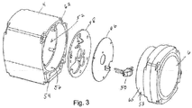
- FIG. 3 A perspective exploded view of motor enclosure 4 and rear end bell 6 with selected components to be contained within are shown in Fig. 3 .
- a power conversion circuit board 46, heat sink, 48, and plug assembly 50 are shown to be contained within cavity 52 of motor enclosure 4.
- collar 54 that includes an inner periphery that forms a flame path surface 56.
- flange 58 extending from rear end bell 6 is flange 58 that includes its flame path surface 60 that will be positioned adjacent flame path surface 56 of collar 54.
- a ledge 62 is formed at the edge of flame path surface 56 and cavity 52 of motor enclosure 4 to serve as an interior joint (see Fig. 4 ) and a contact surface for heat sink 48. This provides the connection between the two for efficiently transferring heat from heat sink 48, into and through motor enclosure 4 and rear end bell 6.
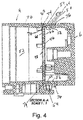
- FIG. 4 A side cross-sectional view of motor enclosure 4 attached to rear end bell 6 as shown in Fig. 4 .
- This view depicts how heat sink 48 is able to transfer heat that is generated by power conversion circuit board 46 to both motor enclosure 4 and rear end bell 6.
- power conversion circuit board 46 is attached to surface 66 of heat sink 48.
- This substantial contact between the two structures means the heat generated by power conversion circuit board 46 (from power loss during the conversion process) may be effectively transferred into the metal body of heat sink 48.
- Second surface 68 of heat sink 48 is in contact with ledge 62 interior of motor enclosure 4. The contact between these two surfaces allow the heat that is transferred from power conversion circuit board 46 and into heat sink 48 via first surface 66 to further transfer through contact between ledge 62 and second surface 68 into the heat conductive body 70 of motor enclosure 4.
- first surface 66 of heat sink 48 also engages edge 72, located at the periphery of flange 58 of rear end bell 6. Because rear end bell 6 may also be made of a heat conducting material, the direct contact between edge 72 and first surface 66 provides a second pathway to transfer heat away from power conversion circuit board 46 and through heat sink 48 to rear end bell 6. Furthermore, the contact between heat sink 48, motor enclosure 4 and rear end bell 6 extends the circumference of those structures in cavity 52. Accordingly, heat sink 48 has the availability of all the heat transfer material embodied in both motor enclosure 4 and rear end bell 6 to transfer the heat generated by power conversion circuit board 46.
- heat sink 48 does not interfere with flame path 64 located at the connection of motor enclosure 4 and rear end bell 6. Flame path surfaces 56 and 60 still operate as normal with interior joint 74 still available to receive any combustion despite the presence of heat sink 48 and can extinguish any combustion before reaching exterior joint 76. Accordingly, this configuration allows heat sink 48 to exploit the heat conductive materials of both motor enclosure 4 and heat sink 6 without any need for fans or venting. This configuration also allows the flame path between those two structures to operate as normal. It is notable that a seam still exists between ledge 62 and second surface 68 of heat sink 48 as well as perimeter surface 78 of heat sink 48 and flame path surface 56 of collar portion 54 of motor enclosure 4. This means any ignition that occurs within cavity 52, it can still exit between ledge 62, and second surface 68 and travel between perimeter surface 78, flame path surface 60 and flame path surface 56 before reaching exterior joint 76.
- Another illustrative embodiment of the present disclosure is directed to a motor status feedback signal generating system.
- This system generates status feedback tones within the motor located inside the motor enclosure to convey particular operating conditions of the motor.
- a circuit board such as circuit board 46 discussed with respect the prior embodiment may include a motor controller.
- the status feedback signal may be audible or imperceptible.
- the motor status feedback signal generating system may produce an audio signal that is imperceptible to a human but can be detected by a microphone and processed by a device such as a computer or smart phone to convey the motor status.
- the motor controller includes a microprocessor that operates the motor.
- the motor controller causes the rotor to rotate.
- a stator surrounds the rotor and includes a series of opposing pairs of windings. Current is run through these opposing pairs of windings in a concentric manner to create a moving electromagnetic force.
- a magnet on the rotor is attracted to that moving electromagnetic force.
- opposing pairs of windings that surround the rotor are energized in a sequence one after another, they create the moving electromagnetic force around a circle.
- the magnet on the rotor being attracted to the electromagnetic force chases the moving electromagnetic force thereby causing the rotor to rotate.
- the motor controller may control the motor's speed.
- any openings or joints must have a flame path to extinguish any combustion that occurs within the motor enclosure before it can reach exterior of the motor enclosure. This, as previously discussed, adds complexity and cost to the motor enclosure. It can therefore be necessary to have only a minimum number of openings needed in the motor enclosure to operate the motor. In the case of pump 2, the openings may be limited to the power supply (e.g., power cord) and the motor shaft (not shown). All of the other components of the motor including the motor controller, stator, windings, and any other structural or electronic components are contained within the motor enclosure.
- the motor controller In addition to operating the motor, the motor controller has the capability to monitor the functions of the motor to ensure that it is operating properly, and if not, diagnose the problem. This capability is not uncommon to motor controllers.
- a motor controller can detect fault conditions with a motor such as over or under voltages, high temperatures, application faults, battery fault, etc.
- the problem within the context of an explosion-proof motor enclosure is attempting to convey those diagnosed faults to the operator.
- audiovisual indicators such as displays, lights, or external speakers, all require wires to be sent out through the motor enclosure between the motor and the outside environment. To do this requires additional complexity and expense to the pump. This is because an additional flame path will have to be created for each opening. Creating the additional needed flame path may be difficult just to accommodate these wires.
- an illustrative embodiment of the present disclosure provides a means for creating an alert scheme to convey operating status of the motor inside the explosion-proof motor enclosure without having to extend any wires or components from the interior to the exterior of the motor enclosure.
- the motor itself may be employed by the motor controller to generate status feedback signals that are perceptible exterior of the motor enclosure and can indicate different status alerts about the motor or application. Allowing the operator to receive feedback without the need to create additional flame paths in the motor enclosure allows for simpler construction while providing enhanced operation of the pump.
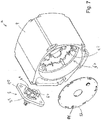
- FIG. 5 A perspective view of motor enclosure 4 with rear end bell 6 and pump 2 is shown in Fig. 5 .
- This view demonstrates an explosion-proof pump enclosure where there are no openings.
- motor enclosure 4 and rear end bell 6 do not extend any wires or other structures exterior of same to provide operational feedback to the operator exterior of pump 2.
- the motor and its attendant structures are all isolated within motor enclosure 4 while generating status signals that can be perceived exterior of pump 2.
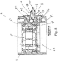
- FIG. 6 An exploded view of motor enclosure 4 and rear end bell 6 is shown in Fig. 6 .
- This view also depicts motor stator portion 80 and motor controller 82.
- Motor stator portion 80 and motor controller 82 are configured to fit into cavity 52 of motor enclosure 4.
- This view along with the view of Fig. 5 allows the skilled artisan to appreciate how motor stator portion 80 and motor controller 82 are isolated from exterior of pump 2.
- motor controller 82 operates motor 80 is by supplying current in a sequential fashion to winding pairs that surround the rotor on the stator. To accomplish this, however, requires specific modulated voltages in sequence around the coils of the stator. That said, if the voltage is not sufficient or is sequenced around the stator wire windings improperly, the rotor will not turn. Changing the frequency of the wave form of the current supplied to the motor although not being sufficient to cause the rotor to rotate, will cause the opposing pairs of wires of the stator to vibrate, not unlike piano or guitar wires. The effect of this is a status feedback signal being generated by the motor itself.
- a motor including motor stator portion 80 in motor enclosure 4 may operate at a PWM (pulse width modulation) frequency of 15,000 hertz.
- PWM pulse width modulation
- supplying current to the opposed windings in the stator in a rotational sequence at a rotational frequency of 120 hertz will cause the rotor in the motor to spin and operate the pump.
- 1,500 hertz is supplied to the opposed windings, the rotor will not rotate but will only cause the wires to vibrate producing the status feedback signal.
- ISR interrupt service routine
- motor controller 82 can send an appropriate frequency signal to one or more of the opposed windings on the stator to cause them to vibrate. That resulting status feedback signal will be perceptible by the operator to indicate there is a fault with the motor or application.
- the frequency and duration of the vibrating wires may be changed so each of the several varieties of faults can each be assigned a unique tone or tone sequence to convey to the operator the precise type of fault that is occurring with the motor.
- motor controller 82 can send an appropriate signal frequency to the motor windings for a period of time, illustratively 0.3 seconds, stop the tone for a second period of time, for example 0.2 seconds, and then repeat.
- a period of time illustratively 0.3 seconds
- stop the tone for a second period of time, for example 0.2 seconds
- repeat In an almost Morse-code-like fashion, the particular pitch of the tones and durations of same may indicate to the operator that there is a specific fault - such as a high temperature fault.
- motor controller 82 may produce a unique sequence of tones. These tones may also last for different durations and intervals that will be unique to that specific fault. By hearing this sequence of tone, the operator will know there is a low battery fault.
- tones are employed to indicate fault conditions. Distinguishing tones may be created by changing the pitch and the number of tones per fault. For example, "application/installation” and “hardware” faults may be identified by sets of tones that are distinguishable by different ordered combinations of high or low pitches.
- Tables I and II depict several potential pump, motor, or application fault conditions. The Tables are divided between “application/installation faults” and “hardware faults.” The three-tone Table lists “application/installation” faults that identify installation issues related to the pump such as priming or supply voltage, for example. The four-tone Table indicates "hardware" faults which identify conditions outside the operating parameters of the pump such as hardware and motor overtemperatures.
- an up arrow “T” means high tone and a down arrow “ ⁇ ” means low tone.
- the tone arrangements may be predetermined so the user will know which fault condition is indicated by listening to the tones generated by the motor inside the enclosure.
- Table I Three-Tone Faults (Application/Installation Faults) Tones Condition ⁇ Low battery voltage (auto shut-off) ⁇ High battery voltage (auto shut-off) ⁇ Locked rotor (auto shut-off) ⁇ Priming/Suction/Lift failure Table II: 4-Tone Faults (Hardware faults) Tones Condition ⁇ Hardware fault (auto shut-off) ⁇ Hardware overtemperature (auto shut-off) ⁇ Motor overtemperature (auto shut-off) ⁇ Motor overvoltage (auto shut-off) ⁇ Motor undervoltage (auto shut-off)
- a hardware overtemperature fault may include four tones composed of one low tone, one high tone, and then two succeeding low tones.
- a motor overtemperature fault may be composed of two low tones followed by two successive high tones.
- a digital audio recorder, telephone, or phone app may be used to record the sounds and send them to technical support to further diagnose and/or suggest repair options.
- Another illustrative embodiment of the present disclosure provides a switch assembly that activates and deactivates the pump motor but without any physical contact with the motor or motor controller.
- adding more openings in an explosion proof motor enclosure requires flame paths and special design considerations that add complexity and cost to the pump. Because of this, the fewer openings in the explosion-proof motor enclosure there are the simpler the pump construction and hence, the less expensive it is to manufacture.
- many pumps, particularly those dispensing fuels include a pivoting lever where rotation in one direction activates the pump, and rotation in the reverse direction deactivates the pump.
- An illustrative embodiment of the present disclosure includes an on and off switch for the pump motor that is part of the lever, but not part of the motor controller that activates the motor. No part of the switch comes into physical contact with any component of the motor through the motor enclosure. Instead, the switch includes a magnet or magnets that remain exterior of the motor enclosure but are detectible by a magnetic sensor located inside the motor enclosure. The magnets create a magnetic field that passes through the material of the motor enclosure (typically aluminum) and is readable by the sensor inside the enclosure. The sensor itself is in electric communication with the motor controller so that when a magnetic field having particular characteristics is detected by the sensor, it will send a signal to the motor controller to either activate or deactivate the motor. This is all accomplished without any part of the switch physically extending through the motor enclosure wall and contacting the components inside.
- lever assembly having a switch lever mount that may be made of steel, iron, or other like material.
- This lever mount serves as a shield for the magnet to prevent any operational interference or deliberate attempts to create an alternate magnetic field in order to activate the sensor in the motor enclosure.
- the magnets on the switch may be located on the shield but opposite the external side of same. In other words, the shield is sandwiched between the switch's lever arm and the actual magnets. This means the magnets will face the motor enclosure while the lever arm faces the exterior environment of the pump assembly.
- the senor is configured to activate the motor only upon detecting a magnetic field having particular characteristics.
- the internal sensor must detect a magnetic field having a predetermined strength and alignment in order for the sensor to initiate activating the motor.
- the shield extends laterally or transverse from the magnet(s) so the magnet(s) are uniquely positioned and oriented to produce the requisite strength and (in conjunction with movement by the lever) predetermined alignment to signal to the sensor to either activate or deactivate the pump motor. It is appreciated that in other embodiments, such magnetic switching may be used to activate other internal components within the motor enclosure.
- FIG. 7 A perspective exploded detail view of components of fluid transfer pump 2 is shown in Fig. 7 .
- motor enclosure 4 Within cavity 52 of enclosure 4 is motor stator 80 along with internal magnetic sensor 84.
- motor controller circuit board 82 is fitted into cavity 52 of motor enclosure 4 as previously discussed.
- switch mechanism assembly 8 Shown as part of switch mechanism assembly 8 is illustratively a pair of magnets 86 and 88 to create the magnetic field to be detected by internal magnetic sensor 84.
- two magnets are used so as to create a more complex magnetic field that is more difficult to mimic.
- a single magnet or other magnetic schemes may be employed.
- Such, alternatives serve the same principle as defining a magnetic field having a particular characteristic or characteristics that must be detected by magnetic sensor 84 in order to activate or deactivate any component - particularly the motor - in motor enclosure 4.
- magnets extend from shield 90. Having magnets 86 and 88 extend from magnet 90 helps particularize the positioning of the magnets relative to the sensor 84 inside motor enclosure 4. This further helps ensure the magnetic field generated by the magnets to ensure only magnets in that particular location will produce the strength needed to be read by the sensor 84.
- shield 90 extends beyond the periphery of magnet casing 89, and, thus, magnets 86 and 88 to serve as shielding so either intentional or incidental magnetic fields from the outside environment will not interfere with the magnetic field intending to activate sensor 84.
- FIG. 8 A top downward looking cross-sectional view of a portion of fluid transfer pump assembly 2 is shown in Fig. 8 .
- This view depicts motor enclosure 4 with motor stator 80 shown housed within cavity 52.
- Another aspect of motor enclosure 4 is switch recess 92 configured to receive a portion of switch mechanism assembly 8.
- switch recess 92 receives magnet casing 89 that holds magnets 86 and 88.
- a counter sink 94 is illustratively formed on the periphery of switch recess 92 and is configured to receive shield 90 from switch mechanism assembly 8. It is evident from this view how magnets 86 and 88 may be contained in cavity 92 while being shrouded by shield 90. It should be appreciated from this view that cavity 92 and counter sink 94 are formed in the exterior of motor enclosure 4. They do not extend in any way into cavity 52. In other words, switch recess 92 and counter sink 94 are isolated from cavity 52.
- a pivot shaft 96 as part of switch shaft assembly 14, is disposed through bore 97 of collar 98 and extends into switch recess 92. Pivot shaft 96 may be secured in bore 97 via fastener 18. Pivot shaft 96 is also attached to magnet casing 89 in order to pivot magnets 86 and 88 (see, also, Figs. 7 and 9 ) to move same between activation and deactivation positions.
- FIGS. 9A and 9B Side cross-sectional views of motor enclosure 4 are shown in Figs. 9A and 9B . These views depict how magnet casing 89 may be pivoted by pivot shaft 96 in order to move magnets 86 and 88 to create the different characteristics of the magnetic field. Again, it is the different characteristics of the magnetic field that indicate to sensor 84 (see, also, Fig. 7 ) whether the motor should be activated or deactivated. It is appreciated from these views how the spacing between magnets 86 and 88, as well as their positioning in proximity (see, also, Figs. 7 and 8 ), create a unique magnetic field characteristic for sensor 84 to detect. Lastly, motor controller circuit board 82 is also shown in this view.
Abstract
Description
- The present disclosure is related to fluid transfer pump assemblies, and particularly to such pump assemblies that have heat dissipation, status feedback signals, and switching functionality in explosion-proof motor enclosure environments.
- Fluid transfer pumps move fluid from one location to another. One example includes a pump that moves hazardous fluid such as gasoline from a storage tank to a vehicle. The pump may employ vanes, diaphragms, or other like structures that are rotated or oscillated inside the pump via some motive force such as an electric motor. The vanes are located in a pump enclosure that is in fluid communication with inlet and outlet manifolds. The inlet manifold may also be in communication with the gasoline in the storage tank while the outlet manifold may also be attached to a hose or other structure configured to deliver the gasoline to another location. As the motor rotates the vanes, a vacuum is created in the pump enclosure to cause the gasoline already present in the tank to be drawn up through the inlet manifold. The vanes then rapidly push the gasoline out through the outlet manifold and the hose, to be delivered to the other location. A nozzle or other type of valve structure may be attached at the other end of the hose to selectively dispense the pumped gasoline.
- An electric motor is a suitable means for rotating the vanes inside the pump. The motor is also able to generate enough rotational velocity to effectively draw up and dispense the fluid at a sufficient rate.
- Fluids like gasoline, however, may pose a risk when utilizing electric motors since such motors have a propensity to produce heat, sparks and arcs, and even flames during abnormal conditions. Placing such motors in potentially flammable environments can, therefore, be hazardous. That is why electric motors are housed in explosion-proof enclosures. These enclosures prevent any internal explosion from propagating to a surrounding explosive atmosphere.
- One manner of mitigating explosions that occur inside the motor enclosure from propagating to outside the motor enclosure is to provide a flame path at the joint between the motor enclosure and end bell. The flame path may be an extended seam located at the motor enclosure joint where the motor enclosure and end bell couple to each other. Illustratively, the end bell may include an extended flange sized to fit against an elongated collar on the motor enclosure. The result is a pathway located between the spaced-apart interior and exterior seams of the enclosure and end bell. The space between the extended flange and collar provides a pathway that will extinguish any flames generated by an explosion inside the enclosure. This prevents the explosion from reaching the external explosive environment thereby eliminating risk of igniting any flammable concentration of vapors outside of the enclosure.
- As the skilled artisan will appreciate, creating these flame paths adds expense and complexity to the motor enclosure and, thus, the pump as a whole. Further exacerbating the issue is if any additional ports or openings are needed. In these instances another flame path will be needed for each additional opening. In other words, more openings in the motor enclosure means more flame paths which means more cost.
- Illustrative embodiments of this present disclosure provide multiple solutions for operating and enhancing the fluid pump motor located inside the explosion-proof motor enclosure, but without needing additional openings requiring additional flame paths, and, thus, additional costs.
- An illustrative embodiment of the present disclosure includes an explosion-proof motor enclosure that comprises a heat sink for efficiently transferring heat generated by components located within the enclosure, but without requiring openings in the enclosure. Another illustrative embodiment of the present disclosure comprises a status feedback signal system that conveys operating conditions of the motor, again, without requiring additional openings extend through the motor enclosure. Another illustrative embodiment of the present disclosure provides a switch system to activate and deactivate the electric motor. And yet again, this is accomplished without requiring additional openings in the motor enclosure.
- Another illustrative embodiment of the present disclosure provides a fluid transfer pump assembly comprising: a motor enclosure assembly formed by a motor enclosure and an end bell; wherein the motor enclosure and the end bell join together to form a motor cavity sized to receive a motor; wherein the motor enclosure includes a collar that extends from the motor enclosure at a collar base, encircles a portion of the motor cavity, and terminates at a collar end distal from the collar base; wherein the collar includes a collar surface; wherein the end bell includes a flange that extends from the end bell at a flange base, encircles a portion of the motor cavity, and terminates at a flange end distal from the flange base; wherein the flange includes a flange surface; wherein when the motor enclosure and the end bell are joined together to form the motor cavity the collar surface faces the flange surface to form a flame path between the collar and flange surfaces; wherein when the motor enclosure and the end bell are joined together to form the motor cavity the collar base is located adjacent the flange end to form an interior-only joint that faces the motor cavity but not located exterior of the motor enclosure assembly; wherein when the motor enclosure and the end bell are joined together to form the motor cavity the flange base is located adjacent the collar end to form an exterior-only joint that is located exterior of the motor cavity but does not face the motor cavity; wherein the flame path extends from the interior-only joint to the exterior-only joint; a heat sink composed of a panel positionable at the interior-only joint of the motor enclosure assembly; wherein the panel of the heat sink has a first surface, a perimeter surface, and a second surface such that the second surface is located adjacent the perimeter surface and opposite the first surface; and a heat generating power conversion circuit board that is attachable to the panel of the heat sink at a location selected from the group consisting of the first surface and the second surface; wherein a portion of the first surface of the panel of the heat sink abuts the collar base at the interior-only joint; wherein a portion of the second surface of the panel of the heat sink abuts the flange end at the interior-only joint; and wherein the perimeter surface of the panel of the heat sink does not interfere with the flame path extending from the interior-only joint to the exterior-only joint of the motor enclosure assembly.
- In the above and other illustrative embodiments, the fluid transfer pump assembly may further comprise: the motor cavity being cylindrical, the collar surface of the motor enclosure being cylindrical, and the flange surface of the end bell being cylindrical; the panel of the heat sink having a circular shape such that the end surface of the panel of the heat sink is located adjacent the cylindrical collar surface of the motor enclosure; the panel of the heat sink is located only interior of the motor enclosure assembly wherein no portion of the heat sink extends exterior of the motor enclosure assembly, and wherein no vents in the motor enclosure assembly are configured to dissipate heat from the heat-generating power conversion circuit board; a pump enclosure attached to the motor enclosure assembly; and the motor enclosure and end bell are both made of a heat-conducting material.
- Another illustrative embodiment of the present disclosure provides a fluid transfer pump assembly comprising: a motor enclosure assembly that forms a motor cavity sized to receive a motor; wherein the motor enclosure includes a flame path composed of a pathway formed by two facing surfaces of the motor enclosure; wherein the pathway is formed by the two facing surfaces of the motor enclosure that extend from an interior joint to an exterior joint; wherein the interior joint faces the motor cavity and the exterior joint faces exterior of the motor enclosure assembly; and a heat sink located in the motor cavity of the motor enclosure assembly; wherein a portion of the heat sink abuts the interior joint; and wherein the heat sink does not interfere with the flame path extending from the interior joint to the exterior joint of the motor enclosure assembly.
- In the above and other illustrative embodiments, the fluid transfer pump assembly may further comprise: the motor enclosure assembly being composed of a first motor enclosure portion and a second motor enclosure portion; the first motor enclosure portion includes a first facing surface of the two facing surfaces, and the second motor enclosure portion includes a second facing surface of the two facing surfaces; the interior joint includes a first joint surface of the first motor enclosure portion and a second joint surface of the second motor enclosure surface; the portion of the heat sink that abuts the interior joint contacts both the first and second joint surfaces such that heat in the heat sink transfers to the first and second motor enclosure portions; the interior joint encircles the motor cavity, a cross-sectional profile of the motor cavity is circular, square, oval, quadrilateral, and polygonal; the first and second motor enclosure portions are separable; the portion of the heat sink that abuts the interior joint includes a periphery that extends about the perimeter of the heat sink; the periphery abuts the interior joint of the motor enclosure assembly; a heat generating power conversion circuit board is attachable to the heat sink and transfers heat to the heat sink.
- Another illustrative embodiment of the present disclosure provides a fluid transfer pump assembly comprising: a motor enclosure assembly that forms a motor cavity sized to receive a motor; wherein the motor enclosure includes a flame path; wherein the flame path extends from an interior joint to an exterior joint; wherein the interior joint faces the motor cavity and the exterior joint faces exterior of the motor enclosure assembly; and a heat sink located in the motor cavity of the motor enclosure assembly; wherein a portion of the heat sink abuts the interior joint; and wherein no portion of the heat sink extends exterior to the motor enclosure assembly.
- In the above and other illustrative embodiments, the fluid transfer pump assembly may further comprise: the heat sink does not interfere with the flame path that extends from the interior joint to the exterior joint; the motor cavity including a motor controller that supplies power to a motor having a rotor and a stator, wherein the stator includes a plurality of pole pairs of wire windings that create a moving electromagnetic force to rotate the rotor, wherein the motor controller upon receiving signals of a condition of the motor, directs current to at least one pole pair of wire windings at a voltage that does not cause the motor to rotate, but causes the at least one pole pair of wire windings to vibrate to create a status feedback signal; and the motor cavity includes a switch assembly that comprises at least one magnet located on a shield extending transverse from that magnet, a switch actuator located adjacent to the shield opposite the at least one magnet, wherein the switch is engageable with the magnet through the shield such that as the switch actuator moves the magnet moves, wherein the magnet fits into a space on the motor enclosure that is spaced apart from the motor cavity in the motor enclosure, a magnetic field sensor located inside the motor cavity of the motor enclosure assembly and isolated from exterior of the motor enclosure cavity, wherein the magnetic field sensor is in electric communication with a motor controller to selectively supply current to the motor to operate same, wherein the magnetic field sensor produces a signal when it detects a magnetic field of a predefined characteristic generated by the magnet. Illustratively, the motor controller interprets the signal generated by the magnetic field sensor and acts to switch on/off based on predefined parameters.
- Additional features and advantages of the fluid transfer pump assembly will become apparent to those skilled in the art upon consideration of the following detailed descriptions exemplifying the best mode of carrying out the fluid transfer pump assembly as presently perceived.
- The concepts described in the present disclosure are illustrated by way of example and not by way of limitation in the accompanying figures. For simplicity and clarity of illustration, elements illustrated in the figures are not necessarily drawn to scale. For example, the dimensions of some elements may be exaggerated relative to other elements for clarity. Further, where considered appropriate, reference labels may be repeated among the figures to indicate corresponding or analogous elements.
-
Fig. 1 is a front perspective view of a fluid pump assembly according to an illustrative embodiment of the present disclosure; -
Fig. 2 is a reverse perspective view of the fluid pump assembly; -
Fig. 3 is a perspective exploded view of the motor enclosure and rear end bell portions, along with selected components to be contained within; -
Fig. 4 is a side cross-sectional view of the motor enclosure attached to the rear end bell; -
Fig. 5 is a perspective view of the motor enclosure, rear end bell, and pump enclosure portions of the fluid pump assembly; -
Fig. 6 is an exploded view of the motor enclosure and rear end bell; -
Fig. 7 is a perspective exploded detail view of the switch assembly, motor enclosure, and motor controller board components of the fluid transfer pump assembly; -
Fig. 8 is a top downward looking cross-sectional view of a portion of the fluid transfer pump assembly; and -
Figs. 9A and 9B are side cross-sectional views of the motor enclosure and switch mechanism. - Corresponding reference characters indicate corresponding parts throughout the several views. The exemplification set out herein illustrates an embodiment of the fluid transfer pump assembly, in one form, and such exemplification is not to be construed as limiting the scope of the fluid transfer pump assembly in any manner.
- The figures and descriptions provided herein may have been simplified to illustrate aspects that are relevant for a clear understanding of the herein described devices, systems, and methods, while eliminating, for the purpose of clarity, other aspects that may be found in typical devices, systems, and methods. Those of ordinary skill may recognize that other elements and/or operations may be desirable and/or necessary to implement the devices, systems, and methods described herein. Because such elements and operations are well known in the art, and because they do not facilitate a better understanding of the present disclosure, a discussion of such elements and operations may not be provided herein. However, the present disclosure is deemed to inherently include all such elements, variations, and modifications to the described aspects that would be known to those of ordinary skill in the art.
- A front perspective view of
illustrative pump assembly 2 is shown inFig. 1 . As shown,fluid transfer pump 2 includes amotor enclosure 4,rear end bell 6,switch mechanism 8,pump enclosure 10, andmanifolds 12.Motor enclosure 4 is part of an explosion-proof enclosure along withend bell 6 andpump enclosure 10 which prevents any sparks, arcs, and flames, from exiting themotor enclosure 4,rear end bell 6, andpump enclosure 10.Switch mechanism 8, which will be discussed in further detail with respect toFigs. 7 through 9 , is illustratively positioned on the exterior ofmotor enclosure 4 as shown. In the illustrated embodiment,switch mechanism 8 is shown having aswitch shaft assembly 14 attached to switchlever arm 16 viafastener 18. Illustratively, a switch lever handle 20 attached to switchlever arm 16 assists in operatingswitch mechanism 8. Further, lockingportion 22 allows padlocks or other securing structures to secure the nozzle to the pump (not shown). Also shown is anozzle hanger mount 24. It will be appreciated by the skilled artisan thatfluid transfer pump 2 may be configured to pump gasoline or other like hazardous materials in a similar manner to conventional gas station pumps. Particularly, gas dispensing nozzles (not shown) may be employed with thefluid transfer pump 2 and operate in a similar method as their gas station fuel pump nozzle counterpart. - Also shown in this view is
pump enclosure 10 locatedadjacent motor enclosure 4 and capped with arotor cover 26 viafasteners 28. In this illustrative embodiment, pumpenclosure 10 encloses a rotor and vanes that are rotated by an electric motor located inmotor enclosure 4. The rotating vanes to draw up and expel fluid frominlet manifold portion 30 and out throughoutlet manifold portion 32. Also shown are aestheticjoint covers motor enclosure 4 andrear end bell 6, as well asmotor enclosure 4 and pumpenclosure 10. - A reverse perspective view of
fluid transfer pump 2 is shown inFig. 2 . This view also showsmotor enclosure 4,rear end bell 6, pumpenclosure 10, andmanifold 12. Particularly depicted is thepower supply port 42 through which a power cord enters to connect the power converter inmotor enclosure 4 with an exterior power supply, such as a vehicle battery, AC mains, etc. - It will be appreciated by the skilled artisan upon reading this disclosure that the primary components that make up the exterior body of
fluid transfer pump 2 are themotor enclosure 4,rear end bell 6, and pumpenclosure 10.Manifold 12 is indeed part ofpump enclosure 10. It is further appreciated thatrear end bell 6 and pumpenclosure 10 may be attached tomotor enclosure 4 via fasteners such asfastener 44 as shown. It is appreciated, however, that other attaching or fastening means may be employed with the pump so long as the explosion-proof characteristics, as known in the relevant art, are not compromised by attaching the structures together. An important, albeit known, feature of fluid transfer pumps of the type likefluid transfer pump 2 is that it is specifically designed so that the motor located insidemotor enclosure 4 will not produce any flame or explosion that can propagate outside ofmotor enclosure 4. A conventional way of achieving this is to make sure a flame path exists at each motor enclosure opening. - And illustrative embodiment of the present disclosure provides explosion-proof containment between
motor enclosure 4 andrear end bell 6. More specifically, an illustrative embodiment of the present disclosure provides a heat sink mechanism withinmotor enclosure 4 andrear end bell 6 that is capable of dissipating heat while not requiring additional openings in either themotor enclosure 4 orrear end bell 6 that would require adding more flame paths. In this illustrative embodiment, it is contemplated that the motor for use in this pump may be a brushless motor requiring a power converter. - For pumps such as these, they may be powered through battery power. This means 12-24 volts can be supplied to the pump. With new motor technology, particularly with brushless-type motors, it may be necessary to boost the 12-24 volts up to 120 volts direct current. Accordingly, this may require a two stage power converter to supply the needed power to the motor. A consequence of this power conversion, however, is a substantial increase in heat on the circuit boards located inside
enclosure 4. - Dissipating heat from motor components and circuit boards is known. Fans and venting are common means of pulling heat generated by such boards away from the motor. In an explosion-proof motor enclosure environment, fans and venting are not really options, however. Again, how motor enclosures are made explosion-proof is by their ability to extinguish any flames generated by an explosion inside the enclosure through these narrow flame paths located at the joints between connecting enclosure components. Having fans and vents, not only add to the complexity of the pump assembly as a whole, but they end up defeating the ability of
motor enclosure 4 to be explosion-proof. In the motor enclosures of the present disclosure (such asmotor enclosure 4 with end bell 6) it is even more difficult to create heat dissipation without vents. - Accordingly, illustrative embodiment of this present disclosure provides a heat sink system that can transfer heat from the power conversion circuit board (or other structures) away from the internal structures in a motor enclosure without the use of any fans or venting. In an illustrative embodiment, a heat sink plate may be placed in contact with the circuit board or any other structure that produces heat needing to be removed. The heat sink may be fitted between the interior joint portion of the motor enclosure and the interior joint portion of the rear end bell. In this configuration, the plate is in contact with other heat transfer materials (i.e., metal structures) on opposite sides of the heat sink. This metal to metal contact between the heat sink and both the motor enclosure and rear end bell gives increased surface area contact between structures which allows more heat to dissipate. In addition, having the heat sink sandwiched between the interior joint of the flame path of the enclosure means the heat sink has face-to-face contact for effective heat distribution while at the same time not interfering with the flame path structures or require any venting or fans.
- A perspective exploded view of
motor enclosure 4 andrear end bell 6 with selected components to be contained within are shown inFig. 3 . Here, a powerconversion circuit board 46, heat sink, 48, and plugassembly 50 are shown to be contained withincavity 52 ofmotor enclosure 4. Also shown in this view iscollar 54 that includes an inner periphery that forms a flame path surface 56. Likewise, extending fromrear end bell 6 is flange 58 that includes its flame path surface 60 that will be positioned adjacent flame path surface 56 ofcollar 54. Aledge 62 is formed at the edge of flame path surface 56 andcavity 52 ofmotor enclosure 4 to serve as an interior joint (seeFig. 4 ) and a contact surface forheat sink 48. This provides the connection between the two for efficiently transferring heat fromheat sink 48, into and throughmotor enclosure 4 andrear end bell 6. - A side cross-sectional view of
motor enclosure 4 attached torear end bell 6 as shown inFig. 4 . This view depicts howheat sink 48 is able to transfer heat that is generated by powerconversion circuit board 46 to bothmotor enclosure 4 andrear end bell 6. As shown, powerconversion circuit board 46 is attached to surface 66 ofheat sink 48. This substantial contact between the two structures means the heat generated by power conversion circuit board 46 (from power loss during the conversion process) may be effectively transferred into the metal body ofheat sink 48. Second surface 68 ofheat sink 48 is in contact withledge 62 interior ofmotor enclosure 4. The contact between these two surfaces allow the heat that is transferred from powerconversion circuit board 46 and intoheat sink 48 via first surface 66 to further transfer through contact betweenledge 62 and second surface 68 into the heat conductive body 70 ofmotor enclosure 4. This provides a continuous path for heat to transfer and dissipate throughmotor enclosure 4. At the same time, first surface 66 ofheat sink 48 also engages edge 72, located at the periphery offlange 58 ofrear end bell 6. Becauserear end bell 6 may also be made of a heat conducting material, the direct contact between edge 72 and first surface 66 provides a second pathway to transfer heat away from powerconversion circuit board 46 and throughheat sink 48 torear end bell 6. Furthermore, the contact betweenheat sink 48,motor enclosure 4 andrear end bell 6 extends the circumference of those structures incavity 52. Accordingly,heat sink 48 has the availability of all the heat transfer material embodied in bothmotor enclosure 4 andrear end bell 6 to transfer the heat generated by powerconversion circuit board 46. - At the same time, it is notable that
heat sink 48 does not interfere with flame path 64 located at the connection ofmotor enclosure 4 andrear end bell 6. Flame path surfaces 56 and 60 still operate as normal with interior joint 74 still available to receive any combustion despite the presence ofheat sink 48 and can extinguish any combustion before reaching exterior joint 76. Accordingly, this configuration allowsheat sink 48 to exploit the heat conductive materials of bothmotor enclosure 4 andheat sink 6 without any need for fans or venting. This configuration also allows the flame path between those two structures to operate as normal. It is notable that a seam still exists betweenledge 62 and second surface 68 ofheat sink 48 as well asperimeter surface 78 ofheat sink 48 and flame path surface 56 ofcollar portion 54 ofmotor enclosure 4. This means any ignition that occurs withincavity 52, it can still exit betweenledge 62, and second surface 68 and travel betweenperimeter surface 78, flame path surface 60 and flame path surface 56 before reaching exterior joint 76. - Another illustrative embodiment of the present disclosure is directed to a motor status feedback signal generating system. This system generates status feedback tones within the motor located inside the motor enclosure to convey particular operating conditions of the motor. A circuit board such as
circuit board 46 discussed with respect the prior embodiment may include a motor controller. It is appreciated that the status feedback signal may be audible or imperceptible. In an illustrative embodiment, the motor status feedback signal generating system may produce an audio signal that is imperceptible to a human but can be detected by a microphone and processed by a device such as a computer or smart phone to convey the motor status. - The motor controller includes a microprocessor that operates the motor. In other words, the motor controller causes the rotor to rotate. A stator surrounds the rotor and includes a series of opposing pairs of windings. Current is run through these opposing pairs of windings in a concentric manner to create a moving electromagnetic force. A magnet on the rotor is attracted to that moving electromagnetic force. When opposing pairs of windings that surround the rotor are energized in a sequence one after another, they create the moving electromagnetic force around a circle. The magnet on the rotor being attracted to the electromagnetic force chases the moving electromagnetic force thereby causing the rotor to rotate. By increasing or decreasing the amount of current that goes into the windings as well as the rate of the sequence, the motor controller may control the motor's speed.
- In the context of a hazardous fluid pump, it is necessary to have an explosion-proof enclosure for the motor to prevent any combustion that occurs within the motor enclosure from causing an explosion exterior of the enclosure. And in order to accomplish this, any openings or joints must have a flame path to extinguish any combustion that occurs within the motor enclosure before it can reach exterior of the motor enclosure. This, as previously discussed, adds complexity and cost to the motor enclosure. It can therefore be necessary to have only a minimum number of openings needed in the motor enclosure to operate the motor. In the case of
pump 2, the openings may be limited to the power supply (e.g., power cord) and the motor shaft (not shown). All of the other components of the motor including the motor controller, stator, windings, and any other structural or electronic components are contained within the motor enclosure. - In addition to operating the motor, the motor controller has the capability to monitor the functions of the motor to ensure that it is operating properly, and if not, diagnose the problem. This capability is not uncommon to motor controllers. A motor controller can detect fault conditions with a motor such as over or under voltages, high temperatures, application faults, battery fault, etc. The problem within the context of an explosion-proof motor enclosure is attempting to convey those diagnosed faults to the operator. Using audiovisual indicators such as displays, lights, or external speakers, all require wires to be sent out through the motor enclosure between the motor and the outside environment. To do this requires additional complexity and expense to the pump. This is because an additional flame path will have to be created for each opening. Creating the additional needed flame path may be difficult just to accommodate these wires.
- Accordingly, an illustrative embodiment of the present disclosure provides a means for creating an alert scheme to convey operating status of the motor inside the explosion-proof motor enclosure without having to extend any wires or components from the interior to the exterior of the motor enclosure. In this illustrative embodiment, the motor itself may be employed by the motor controller to generate status feedback signals that are perceptible exterior of the motor enclosure and can indicate different status alerts about the motor or application. Allowing the operator to receive feedback without the need to create additional flame paths in the motor enclosure allows for simpler construction while providing enhanced operation of the pump.
- A perspective view of
motor enclosure 4 withrear end bell 6 and pump 2 is shown inFig. 5 . This view demonstrates an explosion-proof pump enclosure where there are no openings. Specifically,motor enclosure 4 andrear end bell 6 do not extend any wires or other structures exterior of same to provide operational feedback to the operator exterior ofpump 2. In other words, the motor and its attendant structures are all isolated withinmotor enclosure 4 while generating status signals that can be perceived exterior ofpump 2. - An exploded view of
motor enclosure 4 andrear end bell 6 is shown inFig. 6 . This view also depictsmotor stator portion 80 andmotor controller 82.Motor stator portion 80 andmotor controller 82 are configured to fit intocavity 52 ofmotor enclosure 4. This view along with the view ofFig. 5 allows the skilled artisan to appreciate howmotor stator portion 80 andmotor controller 82 are isolated from exterior ofpump 2. - As previously identified, how
motor controller 82 operatesmotor 80 is by supplying current in a sequential fashion to winding pairs that surround the rotor on the stator. To accomplish this, however, requires specific modulated voltages in sequence around the coils of the stator. That said, if the voltage is not sufficient or is sequenced around the stator wire windings improperly, the rotor will not turn. Changing the frequency of the wave form of the current supplied to the motor although not being sufficient to cause the rotor to rotate, will cause the opposing pairs of wires of the stator to vibrate, not unlike piano or guitar wires. The effect of this is a status feedback signal being generated by the motor itself. For example, a motor includingmotor stator portion 80 inmotor enclosure 4 may operate at a PWM (pulse width modulation) frequency of 15,000 hertz. In other words, supplying current to the opposed windings in the stator in a rotational sequence at a rotational frequency of 120 hertz will cause the rotor in the motor to spin and operate the pump. But if 1,500 hertz is supplied to the opposed windings, the rotor will not rotate but will only cause the wires to vibrate producing the status feedback signal. - While the motor is running, the motor controller continuously runs interrupt service routine (ISR) loops to check the status of the motor. If the routine detects a fault preventing the
motor 80 from operating properly,motor controller 82 can send an appropriate frequency signal to one or more of the opposed windings on the stator to cause them to vibrate. That resulting status feedback signal will be perceptible by the operator to indicate there is a fault with the motor or application. In addition, the frequency and duration of the vibrating wires may be changed so each of the several varieties of faults can each be assigned a unique tone or tone sequence to convey to the operator the precise type of fault that is occurring with the motor. For example, if an excess temperature fault is detected,motor controller 82 can send an appropriate signal frequency to the motor windings for a period of time, illustratively 0.3 seconds, stop the tone for a second period of time, for example 0.2 seconds, and then repeat. In an almost Morse-code-like fashion, the particular pitch of the tones and durations of same may indicate to the operator that there is a specific fault - such as a high temperature fault. If there is a low battery fault detected,motor controller 82 may produce a unique sequence of tones. These tones may also last for different durations and intervals that will be unique to that specific fault. By hearing this sequence of tone, the operator will know there is a low battery fault. - In an illustrative embodiment, tones are employed to indicate fault conditions. Distinguishing tones may be created by changing the pitch and the number of tones per fault. For example, "application/installation" and "hardware" faults may be identified by sets of tones that are distinguishable by different ordered combinations of high or low pitches. In the illustrative embodiment, the following Tables I and II depict several potential pump, motor, or application fault conditions. The Tables are divided between "application/installation faults" and "hardware faults." The three-tone Table lists "application/installation" faults that identify installation issues related to the pump such as priming or supply voltage, for example. The four-tone Table indicates "hardware" faults which identify conditions outside the operating parameters of the pump such as hardware and motor overtemperatures. As shown in both Tables below, an up arrow "T" means high tone and a down arrow "↓" means low tone. Illustratively, the tone arrangements may be predetermined so the user will know which fault condition is indicated by listening to the tones generated by the motor inside the enclosure.
Table I: Three-Tone Faults (Application/Installation Faults) Tones Condition ↑↓↓ Low battery voltage (auto shut-off) ↑↓↑ High battery voltage (auto shut-off) ↓↑↑ Locked rotor (auto shut-off) ↓↑↓ Priming/Suction/Lift failure Table II: 4-Tone Faults (Hardware faults) Tones Condition ↓↑↑↑ Hardware fault (auto shut-off) ↓↑↓↓ Hardware overtemperature (auto shut-off) ↓↓↑↑ Motor overtemperature (auto shut-off) ↓↓↑↓ Motor overvoltage (auto shut-off) ↓↓↓↑ Motor undervoltage (auto shut-off) - In Table I, the difference between a low battery voltage fault and a high battery voltage fault is the former is indicated by a three tone signal composed of one high tone and then two successive low tones. In contrast, the high battery voltage fault has a signal that is one high tone, one low tone, and then a high again. For the hardware faults in Table II, a hardware overtemperature fault may include four tones composed of one low tone, one high tone, and then two succeeding low tones. In contrast, a motor overtemperature fault may be composed of two low tones followed by two successive high tones. It will be appreciated by the skilled artisan that any combination of status feedback signal sequences may be used to identify any variety of faults.
- By employing precise status feedback signal sequences, not only can the fault types be identified by the operator, but they can also be conveyed to a remote entity. For example, a digital audio recorder, telephone, or phone app may be used to record the sounds and send them to technical support to further diagnose and/or suggest repair options.
- Another illustrative embodiment of the present disclosure provides a switch assembly that activates and deactivates the pump motor but without any physical contact with the motor or motor controller. As discussed previously, adding more openings in an explosion proof motor enclosure requires flame paths and special design considerations that add complexity and cost to the pump. Because of this, the fewer openings in the explosion-proof motor enclosure there are the simpler the pump construction and hence, the less expensive it is to manufacture. Typically, many pumps, particularly those dispensing fuels, include a pivoting lever where rotation in one direction activates the pump, and rotation in the reverse direction deactivates the pump.
- An illustrative embodiment of the present disclosure includes an on and off switch for the pump motor that is part of the lever, but not part of the motor controller that activates the motor. No part of the switch comes into physical contact with any component of the motor through the motor enclosure. Instead, the switch includes a magnet or magnets that remain exterior of the motor enclosure but are detectible by a magnetic sensor located inside the motor enclosure. The magnets create a magnetic field that passes through the material of the motor enclosure (typically aluminum) and is readable by the sensor inside the enclosure. The sensor itself is in electric communication with the motor controller so that when a magnetic field having particular characteristics is detected by the sensor, it will send a signal to the motor controller to either activate or deactivate the motor. This is all accomplished without any part of the switch physically extending through the motor enclosure wall and contacting the components inside.
- Another aspect of an illustrative embodiment of the present disclosure includes the lever assembly having a switch lever mount that may be made of steel, iron, or other like material. This lever mount serves as a shield for the magnet to prevent any operational interference or deliberate attempts to create an alternate magnetic field in order to activate the sensor in the motor enclosure. The magnets on the switch may be located on the shield but opposite the external side of same. In other words, the shield is sandwiched between the switch's lever arm and the actual magnets. This means the magnets will face the motor enclosure while the lever arm faces the exterior environment of the pump assembly.
- In a further illustrative embodiment, the sensor is configured to activate the motor only upon detecting a magnetic field having particular characteristics. For example, the internal sensor must detect a magnetic field having a predetermined strength and alignment in order for the sensor to initiate activating the motor. The shield extends laterally or transverse from the magnet(s) so the magnet(s) are uniquely positioned and oriented to produce the requisite strength and (in conjunction with movement by the lever) predetermined alignment to signal to the sensor to either activate or deactivate the pump motor. It is appreciated that in other embodiments, such magnetic switching may be used to activate other internal components within the motor enclosure.
- A perspective exploded detail view of components of
fluid transfer pump 2 is shown inFig. 7 . Depicted aremotor enclosure 4, motorcontroller circuit board 82, andswitch mechanism assembly 8. Withincavity 52 ofenclosure 4 ismotor stator 80 along with internalmagnetic sensor 84. It is appreciated that motorcontroller circuit board 82 is fitted intocavity 52 ofmotor enclosure 4 as previously discussed. Shown as part ofswitch mechanism assembly 8 is illustratively a pair ofmagnets magnetic sensor 84. In this illustrative embodiment, two magnets are used so as to create a more complex magnetic field that is more difficult to mimic. It is appreciated, however, that a single magnet or other magnetic schemes may be employed. Such, alternatives serve the same principle as defining a magnetic field having a particular characteristic or characteristics that must be detected bymagnetic sensor 84 in order to activate or deactivate any component - particularly the motor - inmotor enclosure 4. - Further, depicted herein, is how magnets extend from
shield 90. Havingmagnets magnet 90 helps particularize the positioning of the magnets relative to thesensor 84 insidemotor enclosure 4. This further helps ensure the magnetic field generated by the magnets to ensure only magnets in that particular location will produce the strength needed to be read by thesensor 84. In addition,shield 90 extends beyond the periphery ofmagnet casing 89, and, thus,magnets sensor 84. - A top downward looking cross-sectional view of a portion of fluid
transfer pump assembly 2 is shown inFig. 8 . This view depictsmotor enclosure 4 withmotor stator 80 shown housed withincavity 52. Another aspect ofmotor enclosure 4 isswitch recess 92 configured to receive a portion ofswitch mechanism assembly 8. In particular,switch recess 92 receivesmagnet casing 89 that holdsmagnets counter sink 94 is illustratively formed on the periphery ofswitch recess 92 and is configured to receiveshield 90 fromswitch mechanism assembly 8. It is evident from this view howmagnets cavity 92 while being shrouded byshield 90. It should be appreciated from this view thatcavity 92 and counter sink 94 are formed in the exterior ofmotor enclosure 4. They do not extend in any way intocavity 52. In other words,switch recess 92 and counter sink 94 are isolated fromcavity 52. - A
pivot shaft 96, as part ofswitch shaft assembly 14, is disposed through bore 97 ofcollar 98 and extends intoswitch recess 92.Pivot shaft 96 may be secured in bore 97 viafastener 18.Pivot shaft 96 is also attached tomagnet casing 89 in order to pivotmagnets 86 and 88 (see, also,Figs. 7 and9 ) to move same between activation and deactivation positions. - Side cross-sectional views of
motor enclosure 4 are shown inFigs. 9A and 9B . These views depict how magnet casing 89 may be pivoted bypivot shaft 96 in order to movemagnets Fig. 7 ) whether the motor should be activated or deactivated. It is appreciated from these views how the spacing betweenmagnets Figs. 7 and8 ), create a unique magnetic field characteristic forsensor 84 to detect. Lastly, motorcontroller circuit board 82 is also shown in this view. - Although the present disclosure has been described with reference to particular means, materials and embodiments, from the foregoing description, one skilled in the art can easily ascertain the essential characteristics of the invention and various changes and modifications may be made to adapt the various uses and characteristics without departing from the spirit and scope of the invention.
- Embodiments of the invention can be described with reference to the following numbered clauses, with preferred features in dependent clauses:
- 1A. A fluid transfer pump assembly comprising:
- a motor enclosure assembly formed by a motor enclosure and an end bell;
- wherein the motor enclosure and the end bell join together to form a motor cavity sized to receive a motor;
- wherein the motor enclosure includes a collar that extends from the motor enclosure at a collar base, encircles a portion of the motor cavity, and terminates at a collar end distal from the collar base;
- wherein the collar includes a collar surface;
- wherein the end bell includes a flange that extends from the end bell at a flange base, encircles a portion of the motor cavity, and terminates at a flange end distal from the flange base;
- wherein the flange includes a flange surface;
- wherein when the motor enclosure and the end bell are joined together to form the motor cavity, the collar surface faces the flange surface to form a flame path between the collar and flange surfaces;
- wherein when the motor enclosure and the end bell are joined together to form the motor cavity the collar base is located adjacent the flange end to form an interior-only joint that faces the motor cavity but not located exterior of the motor enclosure assembly;
- wherein when the motor enclosure and the end bell are joined together to form the motor cavity the flange base is located adjacent the collar end to form an exterior-only joint that is located exterior of the motor cavity and does not face the motor cavity;
- wherein the flame path extends from the interior-only joint to the exterior-only joint;
- a heat sink composed of a panel positionable at the interior-only joint of the motor enclosure assembly;
- wherein the panel of the heat sink has a first surface, a perimeter surface, and a second surface such that the second surface is located adjacent the perimeter surface and opposite the first surface; and
- a heat generating circuit board that is attachable to the panel of the heat sink at a location selected from the group consisting of the first surface and the second surface;
- wherein a portion of the first surface of the panel of the heat sink abuts the collar base at the interior-only joint;
- wherein a portion of the second surface of the panel of the heat sink abuts the flange end at the interior-only joint; and
- wherein the perimeter surface of the panel of the heat sink does not interfere with the flame path extending from the interior-only joint to the exterior-only joint of the motor enclosure assembly.
- 2A. The fluid transfer pump assembly of Claim 1A, wherein the motor cavity is cylindrical, the collar surface of the motor enclosure is cylindrical, and the flange surface of the end bell is cylindrical.
- 3A. The fluid transfer pump assembly of Claim 2A, wherein the panel of the heat sink has a circular shape such that the perimeter surface of the panel of the heat sink is located adjacent the cylindrical collar surface of the motor enclosure.
- 4A. The fluid transfer pump assembly of Claim 1A, wherein the panel of the heat sink is located only interior of the motor enclosure assembly wherein no portion of the heat sink extends exterior of the motor enclosure assembly, and wherein no vents in the motor enclosure assembly are configured to dissipate heat from the heat-generating circuit board.
- 5A. The fluid transfer pump assembly of Claim 1A, further comprising a pump enclosure attached to the motor enclosure assembly.
- 6A. The fluid transfer pump assembly of Claim 1A, wherein the motor enclosure and end bell are both made of a heat-conducting material.
- 7A. A fluid transfer pump assembly comprising:
- a motor enclosure assembly that forms a motor cavity sized to receive a motor;
- wherein the motor enclosure includes a flame path composed of a pathway formed by two facing surfaces of the motor enclosure;
- wherein the pathway is formed by the two facing surfaces of the motor enclosure that extend from an interior joint to an exterior joint;
- wherein the interior joint faces the motor cavity and the exterior joint faces exterior of the motor enclosure assembly; and
- a heat sink located in the motor cavity of the motor enclosure assembly;
- wherein a portion of the heat sink abuts the interior joint; and
- wherein the heat sink does not interfere with the flame path extending from the interior joint to the exterior joint of the motor enclosure assembly.
- 8A. The fluid transfer pump assembly of Claim 7A, wherein the motor enclosure assembly is composed of a first motor enclosure portion and a second motor enclosure portion.
- 9A. The fluid transfer pump assembly of Claim 8A, wherein the first motor enclosure portion includes a first facing surface of the two facing surfaces, and the second motor enclosure portion includes a second facing surface of the two facing surfaces.
- 10A. The fluid transfer pump assembly of Claim 9A, wherein the interior joint includes a first joint surface of the first motor enclosure portion and a second joint surface of the second motor enclosure surface.
- 11A. The fluid transfer pump assembly of Claim 10A, wherein the portion of the heat sink that abuts the interior joint contacts both the first and second joint surfaces such that heat in the heat sink transfers to the first and second motor enclosure portions.
- 12A. The fluid transfer pump assembly of Claim 7A, wherein the interior joint encircles the motor cavity, wherein a cross-sectional profile of the motor cavity is circular, square, oval, quadrilateral, and polygonal.
- 13A. The fluid transfer pump assembly of Claim 9A, wherein the first and second motor enclosure portions are separable.
- 14A. The fluid transfer pump assembly of Claim 12A, wherein the portion of the heat sink that abuts the interior joint includes a periphery that extends about the perimeter of the heat sink.
- 15A. The fluid transfer pump assembly of Claim 14A, wherein the periphery abuts the interior joint of the motor enclosure assembly.
- 16A. The fluid transfer pump assembly of Claim 7A, further comprising a heat generating circuit board is attachable to the heat sink and transfers heat to the heat sink.
- 17A. A fluid transfer pump assembly comprising:
- a motor enclosure assembly that forms a motor cavity sized to receive a motor;
- wherein the motor enclosure includes a flame path;
- wherein the flame path extends from an interior joint to an exterior joint;
- wherein the interior joint faces the motor cavity and the exterior joint faces exterior of the motor enclosure assembly; and
- a heat sink located in the motor cavity of the motor enclosure assembly;
- wherein a portion of the heat sink abuts the interior joint; and
- wherein no portion of the heat sink extends exterior to the motor enclosure assembly.
- 18A. The fluid transfer pump assembly of Claim 17A, wherein the heat sink does not interfere with the flame path that extends from the interior joint to the exterior joint.
- 19A. The fluid transfer pump assembly of Claim 17A, wherein the motor cavity includes a motor controller that supplies power to a motor having a rotor and a stator, wherein the stator includes a plurality of pole pairs of wire windings that create a moving electromagnetic force to rotate the rotor, wherein the motor controller, upon receiving signals of a condition of the motor, directs current to at least one pole pair of wire windings at a voltage that does not cause the motor to rotate, but causes the at least one pole pair of wire windings to vibrate to create a status feedback signal.
- 20A. The fluid transfer pump assembly of Claim 17A, wherein the motor cavity includes a switch assembly that comprises at least one magnet located on a shield extending transverse from that magnet, a switch located adjacent to the shield opposite the at least one magnet, wherein the switch is engagable with the magnet through the shield such that as the switch actuator moves the magnet moves, wherein the magnet fits into a space on the motor enclosure that is spaced apart from the motor cavity in the motor enclosure, a magnetic field sensor located inside the motor cavity of the motor enclosure assembly and isolated from exterior of the motor enclosure cavity, wherein the magnetic field sensor is in electric communication with a motor controller to selectively supply current to the motor to operate same, wherein the magnetic field sensor produces a signal when it detects a magnetic field of a predefined characteristic generated by the magnet.
- 1B. A fluid transfer pump assembly comprising:
- an enclosure that forms a motor cavity sized to receive a motor;
- a controller located inside the enclosure; and
- a motor located inside the motor cavity of the enclosure;
- wherein the motor includes a stator and a rotor;
- wherein the rotor includes a magnet;
- wherein the stator includes a plurality of opposing pairs of wire windings;
- wherein the rotor located between an opposing pair of wire windings of each opposing pair of wire windings of the plurality of opposing pairs of wire windings;
- wherein the plurality of opposing pairs of wire windings are located concentrically around the rotor;
- wherein the controller sequentially directs current through the each opposing pair of wire windings of the plurality of opposing pairs of wire windings concentrically around the rotor so the magnet on the rotor will follow the current through the each opposing pair of wire windings which causes the rotor to rotate;
- wherein the controller also monitors a plurality of conditions of the fluid transfer pump;
- wherein the controller selectively directs current to at least one opposing pair of wire windings of the each opposing pair of wire windings in a manner that does not rotate the rotor;
- wherein the manner in which the controller selectively directs current to the at least one opposing pair of wire windings that does not rotate the rotor is selected from the group consisting at least one of an insufficient amount of current to the at least one opposing pair of wire windings and not sequentially directing the current to the plurality of opposing pairs of wire windings;
- wherein when the controller selectively directs current to the at least one opposing pair of wire windings in a manner that does not rotate the rotor, the at least one opposing pair of wire windings vibrates to produce a signal;
- wherein each of the plurality of monitored conditions of the fluid transfer pump is associated with at least one unique signal;
- wherein when one of the plurality of monitored conditions is detected by the controller the controller selectively directs current to the at least one opposing pair of wire windings in the manner that vibrates the at least one opposing pair of wire windings to produce the at least one unique signal that corresponds to the one of the plurality of monitored conditions.
- 2B. The fluid transfer pump assembly of Claim 1B, wherein the at least one unique signal creates a perceptible feedback exterior of the enclosure.
- 3B. The fluid transfer pump assembly of Claim 2B, wherein the perceptible feedback produced by the at least one unique signal is perceptible by the group consisting at least one of a human and a device.
- 4B. The fluid transfer pump assembly of Claim 1B, wherein the at least one unique signal is a plurality of signals.
- 5B. The fluid transfer pump assembly of Claim 4B, wherein each of the plurality of signals has a unique characteristic, wherein the unique characteristic is selected from the group consisting at least one of frequency, duration, and sequence combinations, to correspond to the each of the plurality of monitored conditions.
- 6B. The fluid transfer pump assembly of Claim 1B, wherein plurality of monitored conditions are selected by the group consisting of low battery voltage, high battery voltage, locked rotor, priming/suction/lift failure, hardware fault, hardware overtemperature, motor overtemperature, motor overvoltage, and motor undervoltage.
- 7B. The fluid transfer pump assembly of Claim 1B, wherein the at least one unique signal is at least one audible signal.
- 8B. A fluid transfer pump assembly comprising:
- an enclosure that forms a motor cavity sized to receive a motor;
- a controller located inside the enclosure; and
- a motor located inside the motor cavity of the enclosure;
- wherein the motor includes a plurality of wire windings;
- wherein the controller monitors at least one condition of the fluid transfer pump;
- wherein the controller selectively directs current to at least one wire winding from the plurality of wire windings to vibrate the at least one wire winding to produce a signal.
- 9B. The fluid transfer pump assembly of Claim 8B, wherein the signal creates a perceptible feedback exterior of the enclosure.
- 10B. The fluid transfer pump assembly of Claim 9B, wherein the perceptible feedback produced by the signal is perceptible by the group consisting at least one of a human and a device.
- 11B. The fluid transfer pump assembly of Claim 8B, wherein the signal is an audible signal.
- 12B. The fluid transfer pump assembly of Claim 8B, wherein the controller selectively directs an insufficient amount of current to the motor to rotate the motor but a sufficient amount of current to vibrate the at least one wire winding.
- 13B. The fluid transfer pump assembly of Claim 8B, wherein the at least one condition of the fluid transfer pump that is monitored by the controller is a plurality of conditions of the fluid transfer pump that is monitored by the controller.
- 14B. The fluid transfer pump assembly of Claim 13B, wherein the signal is a plurality of signals wherein each of the plurality of signals is unique and one of each of the plurality of signals corresponds to one of each condition of the plurality of conditions.
- 15B. The fluid transfer pump assembly of Claim 14B, wherein the each of the plurality of signals has a unique characteristic, wherein the unique characteristic is selected from the group consisting at least one of frequency, duration, and sequence combinations, to correspond to the each of the plurality of conditions.
- 16B. The fluid transfer pump assembly of Claim 15B, wherein the controller selectively directs current to the at least one wire winding from the plurality of wire windings to vibrate the at least one wire winding to produce the unique signal that corresponds to the one of the each condition of the plurality of conditions when experienced by the fluid transfer pump.
- 17B. The fluid transfer pump assembly of Claim 16B, wherein the plurality of conditions are selected by the group consisting of low battery voltage, high battery voltage, locked rotor, priming/suction/lift failure, hardware fault, hardware overtemperature, motor overtemperature, motor overvoltage, and motor undervoltage.
- 1C. A fluid transfer pump assembly comprising:
- a motor;
- an enclosure assembly that forms a motor cavity;
- wherein the motor is located in the motor cavity of the enclosure assembly;
- a controller located in the enclosure assembly to selectively activate and deactivate operation of the motor;
- a magnetic field sensor located inside the enclosure assembly and in communication with the controller;
- a switch assembly located exterior of the enclosure assembly;
- wherein the switch assembly includes at least one magnet that creates a magnetic field adjacent the switch assembly;
- wherein the magnetic field generated by the switch assembly located exterior of the enclosure assembly is detected by the magnetic field sensor located inside the enclosure assembly to selectively activate or deactivate the operation of the motor without physical contact between the switch assembly and the magnetic field sensor.
- 2C. The fluid transfer pump assembly of Claim 1C, wherein the at least one magnet is a plurality of magnets.
- 3C. The fluid transfer pump assembly of Claim 2C, wherein each of the plurality of magnets is spaced apart from each other.
- 4C. The fluid transfer pump assembly of Claim 3C, wherein the magnetic field has characteristics created by at least one of the plurality of magnets, movement of the magnets with respect to the magnetic field sensor, and how the plurality of magnets are spaced apart from each other.
- 5C. The fluid transfer pump assembly of Claim 3C, wherein the magnetic field sensor detects the characteristics of the magnetic field in order to activate or deactivate operation of the motor.
- 6C. The fluid transfer pump assembly of Claim 5C, wherein the switch assembly includes a shaft on which the switch assembly pivots, a portion of the shaft extends into a switch recess, wherein the switch assembly holds and moves the plurality of magnets.
- 7C. The fluid transfer pump assembly of Claim 1C, wherein when the magnetic field is detected by the magnetic field sensor, the field magnetic field sensor directs a signal to the controller to activate or deactivate operation of the motor.
- 8C. The fluid transfer pump assembly of Claim 1C, wherein activation or deactivation of the motor is accomplished without any portion of the switch assembly physically extending through the enclosure wall.
- 9C. The fluid transfer pump assembly of Claim 1C, wherein the switch assembly includes a lever.
- 10C. The fluid transfer pump assembly of Claim 1C, wherein the switch assembly with the at least one magnet generates a magnetic field having a predetermined strength and alignment with respect to the magnetic field sensor.
- 11C. The fluid transfer pump assembly of Claim 1C, wherein the switch assembly further includes a shield that shrouds the at least one magnet.
- 12C. The fluid transfer pump assembly of Claim 6C, wherein the switch assembly further includes a shield that shrouds the at least one magnet, wherein the switch recess includes a countersunk periphery sized to receive a portion of the shield.
Claims (19)
- A fluid transfer pump assembly comprising:a motor enclosure assembly that forms a motor cavity sized to receive a motor;wherein the motor enclosure includes a flame path;wherein the flame path extends from an interior joint to an exterior joint;wherein the interior joint faces the motor cavity and the exterior joint faces exterior of the motor enclosure assembly; anda heat sink located in the motor cavity of the motor enclosure assembly;wherein a portion of the heat sink abuts the interior joint; andwherein no portion of the heat sink extends exterior to the motor enclosure assembly and/or wherein the heat sink does not interfere with the flame path extending from the interior joint to the exterior joint of the motor enclosure assembly.
- The fluid transfer pump assembly of Claim 1, wherein the motor cavity includes a motor controller that supplies power to a motor having a rotor and a stator, wherein the stator includes a plurality of pole pairs of wire windings that create a moving electromagnetic force to rotate the rotor, wherein the motor controller, upon receiving signals of a condition of the motor, directs current to at least one pole pair of wire windings at a voltage that does not cause the motor to rotate, but causes the at least one pole pair of wire windings to vibrate to create a status feedback signal.
- The fluid transfer pump assembly of Claim 1, wherein the motor cavity includes a switch assembly that comprises at least one magnet located on a shield extending transverse from that magnet, a switch located adjacent to the shield opposite the at least one magnet, wherein the switch is engagable with the magnet through the shield such that as the switch actuator moves the magnet moves, wherein the magnet fits into a space on the motor enclosure that is spaced apart from the motor cavity in the motor enclosure, a magnetic field sensor located inside the motor cavity of the motor enclosure assembly and isolated from exterior of the motor enclosure cavity, wherein the magnetic field sensor is in electric communication with a motor controller to selectively supply current to the motor to operate same, wherein the magnetic field sensor produces a signal when it detects a magnetic field of a predefined characteristic generated by the magnet.
- The fluid transfer pump assembly according to any one of the preceding claims, wherein the flame path is composed of a pathway formed by two facing surfaces of the motor enclosure assembly that extend from the interior joint to the exterior joint.
- The fluid transfer pump assembly of any one of the preceding claims, wherein the motor enclosure assembly is composed of a first motor enclosure portion and a second motor enclosure portion.
- The fluid transfer pump assembly of Claim 5 when dependent upon claim 4, wherein the first motor enclosure portion includes a first facing surface of the two facing surfaces, and the second motor enclosure portion includes a second facing surface of the two facing surfaces.
- The fluid transfer pump assembly of Claim 6, wherein the interior j oint includes a first j oint surface of the first motor enclosure portion and a second joint surface of the second motor enclosure surface.
- The fluid transfer pump assembly of Claim 7, wherein the portion of the heat sink that abuts the interior joint contacts both the first and second joint surfaces such that heat in the heat sink transfers to the first and second motor enclosure portions.
- The fluid transfer pump assembly of any one of the preceding claims, wherein the interior joint encircles the motor cavity, wherein a cross-sectional profile of the motor cavity is circular, square, oval, quadrilateral, and polygonal.
- The fluid transfer pump assembly of Claim 9, wherein the portion of the heat sink that abuts the interior joint includes a periphery that extends about the perimeter of the heat sink.
- The fluid transfer pump assembly of Claim 10, wherein the periphery abuts the interior joint of the motor enclosure assembly.
- The fluid transfer pump assembly of Claim 5 or any claim dependent thereon, wherein the first and second motor enclosure portions are separable.
- The fluid transfer pump assembly of any one of the preceding claims, further comprising a heat generating circuit board is attachable to the heat sink and transfers heat to the heat sink.
- The fluid transfer pump assembly according to any one of the preceding claims, wherein:the motor enclosure assembly is formed by a motor enclosure and an end bell, the motor enclosure and the end bell join together to form the motor cavity sized to receive a motor;wherein the motor enclosure includes a collar that extends from the motor enclosure at a collar base, encircles a portion of the motor cavity, and terminates at a collar end distal from the collar base;wherein the collar includes a collar surface;wherein the end bell includes a flange that extends from the end bell at a flange base, encircles a portion of the motor cavity, and terminates at a flange end distal from the flange base;wherein the flange includes a flange surface;wherein when the motor enclosure and the end bell are joined together to form the motor cavity, the collar surface faces the flange surface to form the flame path between the collar and flange surfaces;wherein when the motor enclosure and the end bell are joined together to form the motor cavity the collar base is located adjacent the flange end to form the interior-only joint that faces the motor cavity but not located exterior of the motor enclosure assembly;wherein when the motor enclosure and the end bell are joined together to form the motor cavity the flange base is located adjacent the collar end to form the exterior-only joint that is located exterior of the motor cavity and does not face the motor cavity;wherein the heat sink is composed of a panel positionable at the interior-only joint of the motor enclosure assembly;wherein the panel of the heat sink has a first surface, a perimeter surface, and a second surface such that the second surface is located adjacent the perimeter surface and opposite the first surface; anda heat generating circuit board that is attachable to the panel of the heat sink at a location selected from the group consisting of the first surface and the second surface;wherein a portion of the first surface of the panel of the heat sink abuts the collar base at the interior-only joint;wherein a portion of the second surface of the panel of the heat sink abuts the flange end at the interior-only joint; andwherein the perimeter surface of the panel of the heat sink does not interfere with the flame path extending from the interior-only joint to the exterior-only joint of the motor enclosure assembly.
- The fluid transfer pump assembly of Claim 14, wherein the motor cavity is cylindrical, the collar surface of the motor enclosure is cylindrical, and the flange surface of the end bell is cylindrical.
- The fluid transfer pump assembly of Claim 15, wherein the panel of the heat sink has a circular shape such that the perimeter surface of the panel of the heat sink is located adjacent the cylindrical collar surface of the motor enclosure.
- The fluid transfer pump assembly of any one of Claims 14 to 16, wherein the panel of the heat sink is located only interior of the motor enclosure assembly wherein no portion of the heat sink extends exterior of the motor enclosure assembly, and wherein no vents in the motor enclosure assembly are configured to dissipate heat from the heat-generating circuit board.
- The fluid transfer pump assembly of any one of the preceding claims, further comprising a pump enclosure attached to the motor enclosure assembly.
- The fluid transfer pump assembly of any one of the preceding claims, wherein the motor enclosure and end bell are both made of a heat-conducting material.
Applications Claiming Priority (1)
| Application Number | Priority Date | Filing Date | Title |
|---|---|---|---|
| US15/958,217 US10590939B2 (en) | 2018-04-20 | 2018-04-20 | Fluid pump assembly |
Publications (3)
| Publication Number | Publication Date |
|---|---|
| EP3557061A2 true EP3557061A2 (en) | 2019-10-23 |
| EP3557061A3 EP3557061A3 (en) | 2019-12-04 |
| EP3557061B1 EP3557061B1 (en) | 2022-06-08 |
Family
ID=66218008
Family Applications (1)
| Application Number | Title | Priority Date | Filing Date |
|---|---|---|---|
| EP19169961.0A Active EP3557061B1 (en) | 2018-04-20 | 2019-04-17 | Fluid pump assembly |
Country Status (5)
| Country | Link |
|---|---|
| US (3) | US10590939B2 (en) |
| EP (1) | EP3557061B1 (en) |
| CN (1) | CN110391712A (en) |
| CA (1) | CA3040400A1 (en) |
| MX (1) | MX2019004509A (en) |
Families Citing this family (4)
| Publication number | Priority date | Publication date | Assignee | Title |
|---|---|---|---|---|
| US10590939B2 (en) * | 2018-04-20 | 2020-03-17 | Tuthill Corporation | Fluid pump assembly |
| US11852152B2 (en) * | 2019-10-07 | 2023-12-26 | The Gorman-Rupp Company | Pin vent assembly |
| DE102020106796A1 (en) * | 2020-03-12 | 2021-09-16 | Schwäbische Hüttenwerke Automotive GmbH | Pump insert and pump arrangement with such a pump insert |
| CN116857201A (en) * | 2023-07-11 | 2023-10-10 | 广州安捷制造有限公司 | Swimming pool water pump |
Family Cites Families (18)
| Publication number | Priority date | Publication date | Assignee | Title |
|---|---|---|---|---|
| US4013383A (en) * | 1973-12-03 | 1977-03-22 | Rule Industries, Inc. | Vertical shaft impeller pump apparatus |
| EP0317580B1 (en) | 1987-05-08 | 1993-06-30 | Firma Karl Lutz | Electric motor, in particular a drive motor for a drum pump or submersible pump |
| JP3872104B2 (en) * | 1994-11-07 | 2007-01-24 | デーナ、オートモウティヴ、リミティド | Rotary pump |
| DE29502004U1 (en) * | 1995-02-08 | 1996-06-05 | Hanning & Kahl Gmbh & Co | Explosion-proof electrical machine |
| DE19527879A1 (en) | 1995-07-29 | 1997-01-30 | Lutz Pumpen Gmbh & Co Kg | Electric motor, in particular drive motor for a drum or container pump |
| DE19624145A1 (en) | 1996-06-18 | 1998-01-08 | Wilo Gmbh | Electric motor |
| US5930852A (en) * | 1997-03-21 | 1999-08-03 | Aqua-Flo, Incorporated | Heat exchanging pump motor for usage within a recirculating water system |
| DE19956380C1 (en) * | 1999-11-24 | 2001-01-04 | Bosch Gmbh Robert | Fluid pump for vehicle cooling and heating systems has plastics motor housing with claw plates of claw pole stator formed as integral components thereof |
| JP4034077B2 (en) * | 2002-01-30 | 2008-01-16 | カルソニックカンセイ株式会社 | Cand pump |
| US7036892B2 (en) * | 2003-05-28 | 2006-05-02 | Aisin Seiki Kabushiki Kaisha | Electric powered pump |
| WO2006137766A1 (en) * | 2005-06-22 | 2006-12-28 | Itt Manufacturing Enterprises Inc. | Device for a rotating gland seal |
| US20130259720A1 (en) | 2010-08-25 | 2013-10-03 | Kyle D. Mills | Electric Water Pump With Stator Cooling |
| CN202231561U (en) * | 2011-09-19 | 2012-05-23 | 浙江凯利达防爆机电有限公司 | Radiating explosion-proof motor |
| WO2014116576A1 (en) | 2013-01-28 | 2014-07-31 | Dixon Pumps Inc. | System, apparatus, and method for controlling a motor |
| GB201307257D0 (en) * | 2013-04-22 | 2013-05-29 | Flowork Systems Ii Llc | Conrollable variable flow coolant pump and flow management mechanism |
| GB2517457B (en) * | 2013-08-21 | 2016-06-08 | Pyroban Ltd | Enclosure for electric motor |
| CN105896824A (en) * | 2016-06-16 | 2016-08-24 | 日本电产凯宇汽车电器(江苏)有限公司 | Electric water pump with water cooling and water lubricating functions |
| US10590939B2 (en) * | 2018-04-20 | 2020-03-17 | Tuthill Corporation | Fluid pump assembly |
-
2018
- 2018-04-20 US US15/958,217 patent/US10590939B2/en active Active
-
2019
- 2019-04-16 CA CA3040400A patent/CA3040400A1/en active Pending
- 2019-04-16 MX MX2019004509A patent/MX2019004509A/en unknown
- 2019-04-17 EP EP19169961.0A patent/EP3557061B1/en active Active
- 2019-04-19 CN CN201910319951.8A patent/CN110391712A/en active Pending
-
2020
- 2020-03-16 US US16/819,356 patent/US11346353B2/en active Active
-
2022
- 2022-05-30 US US17/827,864 patent/US20220299037A1/en active Pending
Non-Patent Citations (1)
| Title |
|---|
| None |
Also Published As
| Publication number | Publication date |
|---|---|
| US20190323512A1 (en) | 2019-10-24 |
| CA3040400A1 (en) | 2019-10-20 |
| US20200217323A1 (en) | 2020-07-09 |
| MX2019004509A (en) | 2019-11-21 |
| EP3557061A3 (en) | 2019-12-04 |
| US11346353B2 (en) | 2022-05-31 |
| CN110391712A (en) | 2019-10-29 |
| US10590939B2 (en) | 2020-03-17 |
| EP3557061B1 (en) | 2022-06-08 |
| US20220299037A1 (en) | 2022-09-22 |
Similar Documents
| Publication | Publication Date | Title |
|---|---|---|
| US11346353B2 (en) | Fluid pump assembly | |
| JP4661278B2 (en) | Turbo molecular pump | |
| JP6386470B2 (en) | Electric machine | |
| JP2012021464A (en) | Electric pump | |
| US20150076941A1 (en) | Methods and apparatus for mounting a motor controller on a stator assembly | |
| JPH04322052A (en) | Battery pack for driving and operating electronic medical instrument with battery and manufacture thereof | |
| JP2007282309A (en) | Vehicle motor drive unit | |
| US11181114B2 (en) | Cooling fan | |
| TWI287345B (en) | Motor with a rotation-fan and air cooling device | |
| JP2010048169A (en) | Turbo molecular pump | |
| JP3138105U (en) | Turbo molecular pump | |
| JP4049201B2 (en) | Induction heating device | |
| US20060055893A1 (en) | Method and apparatus for monitoring signals of a projector | |
| US10910925B2 (en) | Circuit board, motor unit, and fan | |
| CN112424460B (en) | Electric control throttle device | |
| WO2021004545A1 (en) | Motor and electric device comprising such motor | |
| KR101953787B1 (en) | Electric water pump and manufacturing method for thereof | |
| EP3916243B1 (en) | Fan for air-gas mixing systems in burners of heating equipment | |
| KR101621390B1 (en) | Power connector for electron clutch | |
| JP2009057880A (en) | Pump device | |
| KR20160146570A (en) | Hydraulic pump with electric generator | |
| KR20130055323A (en) | Cooling fan system | |
| JP3166864U (en) | Turbo unit pump with integrated control unit | |
| JP2014015943A (en) | Control unit integrated type turbo-molecular pump | |
| JP2020145804A (en) | Motor assembly and water supply device |
Legal Events
| Date | Code | Title | Description |
|---|---|---|---|
| PUAI | Public reference made under article 153(3) epc to a published international application that has entered the european phase |
Free format text: ORIGINAL CODE: 0009012 |
|
| STAA | Information on the status of an ep patent application or granted ep patent |
Free format text: STATUS: THE APPLICATION HAS BEEN PUBLISHED |
|
| AK | Designated contracting states |
Kind code of ref document: A2 Designated state(s): AL AT BE BG CH CY CZ DE DK EE ES FI FR GB GR HR HU IE IS IT LI LT LU LV MC MK MT NL NO PL PT RO RS SE SI SK SM TR |
|
| AX | Request for extension of the european patent |
Extension state: BA ME |
|
| PUAL | Search report despatched |
Free format text: ORIGINAL CODE: 0009013 |
|
| AK | Designated contracting states |
Kind code of ref document: A3 Designated state(s): AL AT BE BG CH CY CZ DE DK EE ES FI FR GB GR HR HU IE IS IT LI LT LU LV MC MK MT NL NO PL PT RO RS SE SI SK SM TR |
|
| AX | Request for extension of the european patent |
Extension state: BA ME |
|
| RIC1 | Information provided on ipc code assigned before grant |
Ipc: H02K 5/04 20060101ALI20191031BHEP Ipc: F04B 53/16 20060101AFI20191031BHEP Ipc: F02M 37/00 20060101ALI20191031BHEP Ipc: F04C 15/00 20060101ALI20191031BHEP Ipc: F04D 29/40 20060101ALI20191031BHEP Ipc: H02K 5/136 20060101ALI20191031BHEP |
|
| STAA | Information on the status of an ep patent application or granted ep patent |
Free format text: STATUS: REQUEST FOR EXAMINATION WAS MADE |
|
| 17P | Request for examination filed |
Effective date: 20200602 |
|
| RBV | Designated contracting states (corrected) |
Designated state(s): AL AT BE BG CH CY CZ DE DK EE ES FI FR GB GR HR HU IE IS IT LI LT LU LV MC MK MT NL NO PL PT RO RS SE SI SK SM TR |
|
| STAA | Information on the status of an ep patent application or granted ep patent |
Free format text: STATUS: EXAMINATION IS IN PROGRESS |
|
| 17Q | First examination report despatched |
Effective date: 20200917 |
|
| STAA | Information on the status of an ep patent application or granted ep patent |
Free format text: STATUS: EXAMINATION IS IN PROGRESS |
|
| RIC1 | Information provided on ipc code assigned before grant |
Ipc: H02K 11/33 20160101ALI20210810BHEP Ipc: H02K 11/215 20160101ALI20210810BHEP Ipc: H02K 7/14 20060101ALI20210810BHEP Ipc: H02K 5/136 20060101ALI20210810BHEP Ipc: F02M 37/14 20060101ALI20210810BHEP Ipc: F02M 37/10 20060101ALI20210810BHEP Ipc: F02M 37/00 20060101ALI20210810BHEP Ipc: F04D 29/42 20060101ALI20210810BHEP Ipc: F04D 29/40 20060101ALI20210810BHEP Ipc: F04D 13/06 20060101ALI20210810BHEP Ipc: F04C 15/00 20060101ALI20210810BHEP Ipc: F04C 14/28 20060101ALI20210810BHEP Ipc: F04C 2/344 20060101ALI20210810BHEP Ipc: F04B 53/16 20060101AFI20210810BHEP |
|
| GRAP | Despatch of communication of intention to grant a patent |
Free format text: ORIGINAL CODE: EPIDOSNIGR1 |
|
| STAA | Information on the status of an ep patent application or granted ep patent |
Free format text: STATUS: GRANT OF PATENT IS INTENDED |
|
| INTG | Intention to grant announced |
Effective date: 20211006 |
|
| GRAJ | Information related to disapproval of communication of intention to grant by the applicant or resumption of examination proceedings by the epo deleted |
Free format text: ORIGINAL CODE: EPIDOSDIGR1 |
|
| STAA | Information on the status of an ep patent application or granted ep patent |
Free format text: STATUS: EXAMINATION IS IN PROGRESS |
|
| GRAP | Despatch of communication of intention to grant a patent |
Free format text: ORIGINAL CODE: EPIDOSNIGR1 |
|
| STAA | Information on the status of an ep patent application or granted ep patent |
Free format text: STATUS: GRANT OF PATENT IS INTENDED |
|
| INTC | Intention to grant announced (deleted) | ||
| INTG | Intention to grant announced |
Effective date: 20220204 |
|
| GRAS | Grant fee paid |
Free format text: ORIGINAL CODE: EPIDOSNIGR3 |
|
| GRAA | (expected) grant |
Free format text: ORIGINAL CODE: 0009210 |
|
| STAA | Information on the status of an ep patent application or granted ep patent |
Free format text: STATUS: THE PATENT HAS BEEN GRANTED |
|
| AK | Designated contracting states |
Kind code of ref document: B1 Designated state(s): AL AT BE BG CH CY CZ DE DK EE ES FI FR GB GR HR HU IE IS IT LI LT LU LV MC MK MT NL NO PL PT RO RS SE SI SK SM TR |
|
| REG | Reference to a national code |
Ref country code: AT Ref legal event code: REF Ref document number: 1497099 Country of ref document: AT Kind code of ref document: T Effective date: 20220615 Ref country code: CH Ref legal event code: EP |
|
| REG | Reference to a national code |
Ref country code: DE Ref legal event code: R096 Ref document number: 602019015578 Country of ref document: DE |
|
| REG | Reference to a national code |
Ref country code: IE Ref legal event code: FG4D |
|
| RAP2 | Party data changed (patent owner data changed or rights of a patent transferred) |
Owner name: THE GORMAN-RUPP COMPANY |
|
| REG | Reference to a national code |
Ref country code: LT Ref legal event code: MG9D |
|
| REG | Reference to a national code |
Ref country code: NL Ref legal event code: MP Effective date: 20220608 |
|
| PG25 | Lapsed in a contracting state [announced via postgrant information from national office to epo] |
Ref country code: SE Free format text: LAPSE BECAUSE OF FAILURE TO SUBMIT A TRANSLATION OF THE DESCRIPTION OR TO PAY THE FEE WITHIN THE PRESCRIBED TIME-LIMIT Effective date: 20220608 Ref country code: NO Free format text: LAPSE BECAUSE OF FAILURE TO SUBMIT A TRANSLATION OF THE DESCRIPTION OR TO PAY THE FEE WITHIN THE PRESCRIBED TIME-LIMIT Effective date: 20220908 Ref country code: LT Free format text: LAPSE BECAUSE OF FAILURE TO SUBMIT A TRANSLATION OF THE DESCRIPTION OR TO PAY THE FEE WITHIN THE PRESCRIBED TIME-LIMIT Effective date: 20220608 Ref country code: HR Free format text: LAPSE BECAUSE OF FAILURE TO SUBMIT A TRANSLATION OF THE DESCRIPTION OR TO PAY THE FEE WITHIN THE PRESCRIBED TIME-LIMIT Effective date: 20220608 Ref country code: GR Free format text: LAPSE BECAUSE OF FAILURE TO SUBMIT A TRANSLATION OF THE DESCRIPTION OR TO PAY THE FEE WITHIN THE PRESCRIBED TIME-LIMIT Effective date: 20220909 Ref country code: FI Free format text: LAPSE BECAUSE OF FAILURE TO SUBMIT A TRANSLATION OF THE DESCRIPTION OR TO PAY THE FEE WITHIN THE PRESCRIBED TIME-LIMIT Effective date: 20220608 Ref country code: ES Free format text: LAPSE BECAUSE OF FAILURE TO SUBMIT A TRANSLATION OF THE DESCRIPTION OR TO PAY THE FEE WITHIN THE PRESCRIBED TIME-LIMIT Effective date: 20220608 Ref country code: BG Free format text: LAPSE BECAUSE OF FAILURE TO SUBMIT A TRANSLATION OF THE DESCRIPTION OR TO PAY THE FEE WITHIN THE PRESCRIBED TIME-LIMIT Effective date: 20220908 |
|
| REG | Reference to a national code |
Ref country code: AT Ref legal event code: MK05 Ref document number: 1497099 Country of ref document: AT Kind code of ref document: T Effective date: 20220608 |
|
| PG25 | Lapsed in a contracting state [announced via postgrant information from national office to epo] |
Ref country code: RS Free format text: LAPSE BECAUSE OF FAILURE TO SUBMIT A TRANSLATION OF THE DESCRIPTION OR TO PAY THE FEE WITHIN THE PRESCRIBED TIME-LIMIT Effective date: 20220608 Ref country code: LV Free format text: LAPSE BECAUSE OF FAILURE TO SUBMIT A TRANSLATION OF THE DESCRIPTION OR TO PAY THE FEE WITHIN THE PRESCRIBED TIME-LIMIT Effective date: 20220608 |
|
| REG | Reference to a national code |
Ref country code: DE Ref legal event code: R081 Ref document number: 602019015578 Country of ref document: DE Owner name: THE GORMAN- RUPP COMPANY, MANSFIELD, US Free format text: FORMER OWNER: TUTHILL CORP., FORT WAYNE, IN, US |
|
| PG25 | Lapsed in a contracting state [announced via postgrant information from national office to epo] |
Ref country code: NL Free format text: LAPSE BECAUSE OF FAILURE TO SUBMIT A TRANSLATION OF THE DESCRIPTION OR TO PAY THE FEE WITHIN THE PRESCRIBED TIME-LIMIT Effective date: 20220608 |
|
| PG25 | Lapsed in a contracting state [announced via postgrant information from national office to epo] |
Ref country code: SM Free format text: LAPSE BECAUSE OF FAILURE TO SUBMIT A TRANSLATION OF THE DESCRIPTION OR TO PAY THE FEE WITHIN THE PRESCRIBED TIME-LIMIT Effective date: 20220608 Ref country code: SK Free format text: LAPSE BECAUSE OF FAILURE TO SUBMIT A TRANSLATION OF THE DESCRIPTION OR TO PAY THE FEE WITHIN THE PRESCRIBED TIME-LIMIT Effective date: 20220608 Ref country code: RO Free format text: LAPSE BECAUSE OF FAILURE TO SUBMIT A TRANSLATION OF THE DESCRIPTION OR TO PAY THE FEE WITHIN THE PRESCRIBED TIME-LIMIT Effective date: 20220608 Ref country code: PT Free format text: LAPSE BECAUSE OF FAILURE TO SUBMIT A TRANSLATION OF THE DESCRIPTION OR TO PAY THE FEE WITHIN THE PRESCRIBED TIME-LIMIT Effective date: 20221010 Ref country code: EE Free format text: LAPSE BECAUSE OF FAILURE TO SUBMIT A TRANSLATION OF THE DESCRIPTION OR TO PAY THE FEE WITHIN THE PRESCRIBED TIME-LIMIT Effective date: 20220608 Ref country code: CZ Free format text: LAPSE BECAUSE OF FAILURE TO SUBMIT A TRANSLATION OF THE DESCRIPTION OR TO PAY THE FEE WITHIN THE PRESCRIBED TIME-LIMIT Effective date: 20220608 Ref country code: AT Free format text: LAPSE BECAUSE OF FAILURE TO SUBMIT A TRANSLATION OF THE DESCRIPTION OR TO PAY THE FEE WITHIN THE PRESCRIBED TIME-LIMIT Effective date: 20220608 |
|
| PG25 | Lapsed in a contracting state [announced via postgrant information from national office to epo] |
Ref country code: PL Free format text: LAPSE BECAUSE OF FAILURE TO SUBMIT A TRANSLATION OF THE DESCRIPTION OR TO PAY THE FEE WITHIN THE PRESCRIBED TIME-LIMIT Effective date: 20220608 Ref country code: IS Free format text: LAPSE BECAUSE OF FAILURE TO SUBMIT A TRANSLATION OF THE DESCRIPTION OR TO PAY THE FEE WITHIN THE PRESCRIBED TIME-LIMIT Effective date: 20221008 |
|
| REG | Reference to a national code |
Ref country code: DE Ref legal event code: R097 Ref document number: 602019015578 Country of ref document: DE |
|
| PG25 | Lapsed in a contracting state [announced via postgrant information from national office to epo] |
Ref country code: AL Free format text: LAPSE BECAUSE OF FAILURE TO SUBMIT A TRANSLATION OF THE DESCRIPTION OR TO PAY THE FEE WITHIN THE PRESCRIBED TIME-LIMIT Effective date: 20220608 |
|
| PLBE | No opposition filed within time limit |
Free format text: ORIGINAL CODE: 0009261 |
|
| STAA | Information on the status of an ep patent application or granted ep patent |
Free format text: STATUS: NO OPPOSITION FILED WITHIN TIME LIMIT |
|
| PG25 | Lapsed in a contracting state [announced via postgrant information from national office to epo] |
Ref country code: DK Free format text: LAPSE BECAUSE OF FAILURE TO SUBMIT A TRANSLATION OF THE DESCRIPTION OR TO PAY THE FEE WITHIN THE PRESCRIBED TIME-LIMIT Effective date: 20220608 |
|
| 26N | No opposition filed |
Effective date: 20230310 |
|
| PG25 | Lapsed in a contracting state [announced via postgrant information from national office to epo] |
Ref country code: SI Free format text: LAPSE BECAUSE OF FAILURE TO SUBMIT A TRANSLATION OF THE DESCRIPTION OR TO PAY THE FEE WITHIN THE PRESCRIBED TIME-LIMIT Effective date: 20220608 |
|
| PGFP | Annual fee paid to national office [announced via postgrant information from national office to epo] |
Ref country code: IT Payment date: 20230419 Year of fee payment: 5 Ref country code: DE Payment date: 20230427 Year of fee payment: 5 |
|
| P01 | Opt-out of the competence of the unified patent court (upc) registered |
Effective date: 20230626 |
|
| PGFP | Annual fee paid to national office [announced via postgrant information from national office to epo] |
Ref country code: GB Payment date: 20230427 Year of fee payment: 5 |
|
| REG | Reference to a national code |
Ref country code: CH Ref legal event code: PL |
|
| PG25 | Lapsed in a contracting state [announced via postgrant information from national office to epo] |
Ref country code: LU Free format text: LAPSE BECAUSE OF NON-PAYMENT OF DUE FEES Effective date: 20230417 |
|
| REG | Reference to a national code |
Ref country code: BE Ref legal event code: MM Effective date: 20230430 |
|
| PG25 | Lapsed in a contracting state [announced via postgrant information from national office to epo] |
Ref country code: MC Free format text: LAPSE BECAUSE OF FAILURE TO SUBMIT A TRANSLATION OF THE DESCRIPTION OR TO PAY THE FEE WITHIN THE PRESCRIBED TIME-LIMIT Effective date: 20220608 |
|
| PG25 | Lapsed in a contracting state [announced via postgrant information from national office to epo] |
Ref country code: MC Free format text: LAPSE BECAUSE OF FAILURE TO SUBMIT A TRANSLATION OF THE DESCRIPTION OR TO PAY THE FEE WITHIN THE PRESCRIBED TIME-LIMIT Effective date: 20220608 Ref country code: LI Free format text: LAPSE BECAUSE OF NON-PAYMENT OF DUE FEES Effective date: 20230430 Ref country code: FR Free format text: LAPSE BECAUSE OF NON-PAYMENT OF DUE FEES Effective date: 20230430 Ref country code: CH Free format text: LAPSE BECAUSE OF NON-PAYMENT OF DUE FEES Effective date: 20230430 |
|
| REG | Reference to a national code |
Ref country code: IE Ref legal event code: MM4A |
|
| PG25 | Lapsed in a contracting state [announced via postgrant information from national office to epo] |
Ref country code: BE Free format text: LAPSE BECAUSE OF NON-PAYMENT OF DUE FEES Effective date: 20230430 |
|
| PG25 | Lapsed in a contracting state [announced via postgrant information from national office to epo] |
Ref country code: IE Free format text: LAPSE BECAUSE OF NON-PAYMENT OF DUE FEES Effective date: 20230417 |