EP3557047B1 - Steuerungsverfahren zur vermeidung eines durchgehens der windturbine, entsprechende vorrichtung und windenergieanlage - Google Patents
Steuerungsverfahren zur vermeidung eines durchgehens der windturbine, entsprechende vorrichtung und windenergieanlage Download PDFInfo
- Publication number
- EP3557047B1 EP3557047B1 EP18887198.2A EP18887198A EP3557047B1 EP 3557047 B1 EP3557047 B1 EP 3557047B1 EP 18887198 A EP18887198 A EP 18887198A EP 3557047 B1 EP3557047 B1 EP 3557047B1
- Authority
- EP
- European Patent Office
- Prior art keywords
- crosswind
- wind direction
- angle
- wind turbine
- wind
- Prior art date
- Legal status (The legal status is an assumption and is not a legal conclusion. Google has not performed a legal analysis and makes no representation as to the accuracy of the status listed.)
- Active
Links
Images
Classifications
-
- F—MECHANICAL ENGINEERING; LIGHTING; HEATING; WEAPONS; BLASTING
- F03—MACHINES OR ENGINES FOR LIQUIDS; WIND, SPRING, OR WEIGHT MOTORS; PRODUCING MECHANICAL POWER OR A REACTIVE PROPULSIVE THRUST, NOT OTHERWISE PROVIDED FOR
- F03D—WIND MOTORS
- F03D7/00—Controlling wind motors
- F03D7/02—Controlling wind motors the wind motors having rotation axis substantially parallel to the air flow entering the rotor
- F03D7/04—Automatic control; Regulation
- F03D7/042—Automatic control; Regulation by means of an electrical or electronic controller
-
- F—MECHANICAL ENGINEERING; LIGHTING; HEATING; WEAPONS; BLASTING
- F03—MACHINES OR ENGINES FOR LIQUIDS; WIND, SPRING, OR WEIGHT MOTORS; PRODUCING MECHANICAL POWER OR A REACTIVE PROPULSIVE THRUST, NOT OTHERWISE PROVIDED FOR
- F03D—WIND MOTORS
- F03D7/00—Controlling wind motors
- F03D7/02—Controlling wind motors the wind motors having rotation axis substantially parallel to the air flow entering the rotor
- F03D7/022—Adjusting aerodynamic properties of the blades
- F03D7/0236—Adjusting aerodynamic properties of the blades by changing the active surface of the wind engaging parts, e.g. reefing or furling
-
- F—MECHANICAL ENGINEERING; LIGHTING; HEATING; WEAPONS; BLASTING
- F03—MACHINES OR ENGINES FOR LIQUIDS; WIND, SPRING, OR WEIGHT MOTORS; PRODUCING MECHANICAL POWER OR A REACTIVE PROPULSIVE THRUST, NOT OTHERWISE PROVIDED FOR
- F03D—WIND MOTORS
- F03D17/00—Monitoring or testing of wind motors, e.g. diagnostics
-
- F—MECHANICAL ENGINEERING; LIGHTING; HEATING; WEAPONS; BLASTING
- F03—MACHINES OR ENGINES FOR LIQUIDS; WIND, SPRING, OR WEIGHT MOTORS; PRODUCING MECHANICAL POWER OR A REACTIVE PROPULSIVE THRUST, NOT OTHERWISE PROVIDED FOR
- F03D—WIND MOTORS
- F03D7/00—Controlling wind motors
- F03D7/02—Controlling wind motors the wind motors having rotation axis substantially parallel to the air flow entering the rotor
- F03D7/0204—Controlling wind motors the wind motors having rotation axis substantially parallel to the air flow entering the rotor for orientation in relation to wind direction
- F03D7/0208—Orientating out of wind
- F03D7/0212—Orientating out of wind the rotating axis remaining horizontal
-
- F—MECHANICAL ENGINEERING; LIGHTING; HEATING; WEAPONS; BLASTING
- F03—MACHINES OR ENGINES FOR LIQUIDS; WIND, SPRING, OR WEIGHT MOTORS; PRODUCING MECHANICAL POWER OR A REACTIVE PROPULSIVE THRUST, NOT OTHERWISE PROVIDED FOR
- F03D—WIND MOTORS
- F03D7/00—Controlling wind motors
- F03D7/02—Controlling wind motors the wind motors having rotation axis substantially parallel to the air flow entering the rotor
- F03D7/022—Adjusting aerodynamic properties of the blades
- F03D7/024—Adjusting aerodynamic properties of the blades of individual blades
-
- F—MECHANICAL ENGINEERING; LIGHTING; HEATING; WEAPONS; BLASTING
- F03—MACHINES OR ENGINES FOR LIQUIDS; WIND, SPRING, OR WEIGHT MOTORS; PRODUCING MECHANICAL POWER OR A REACTIVE PROPULSIVE THRUST, NOT OTHERWISE PROVIDED FOR
- F03D—WIND MOTORS
- F03D7/00—Controlling wind motors
- F03D7/02—Controlling wind motors the wind motors having rotation axis substantially parallel to the air flow entering the rotor
- F03D7/0244—Controlling wind motors the wind motors having rotation axis substantially parallel to the air flow entering the rotor for braking
-
- F—MECHANICAL ENGINEERING; LIGHTING; HEATING; WEAPONS; BLASTING
- F03—MACHINES OR ENGINES FOR LIQUIDS; WIND, SPRING, OR WEIGHT MOTORS; PRODUCING MECHANICAL POWER OR A REACTIVE PROPULSIVE THRUST, NOT OTHERWISE PROVIDED FOR
- F03D—WIND MOTORS
- F03D7/00—Controlling wind motors
- F03D7/02—Controlling wind motors the wind motors having rotation axis substantially parallel to the air flow entering the rotor
- F03D7/0256—Stall control
-
- F—MECHANICAL ENGINEERING; LIGHTING; HEATING; WEAPONS; BLASTING
- F03—MACHINES OR ENGINES FOR LIQUIDS; WIND, SPRING, OR WEIGHT MOTORS; PRODUCING MECHANICAL POWER OR A REACTIVE PROPULSIVE THRUST, NOT OTHERWISE PROVIDED FOR
- F03D—WIND MOTORS
- F03D7/00—Controlling wind motors
- F03D7/02—Controlling wind motors the wind motors having rotation axis substantially parallel to the air flow entering the rotor
- F03D7/0264—Controlling wind motors the wind motors having rotation axis substantially parallel to the air flow entering the rotor for stopping; controlling in emergency situations
-
- F—MECHANICAL ENGINEERING; LIGHTING; HEATING; WEAPONS; BLASTING
- F05—INDEXING SCHEMES RELATING TO ENGINES OR PUMPS IN VARIOUS SUBCLASSES OF CLASSES F01-F04
- F05B—INDEXING SCHEME RELATING TO WIND, SPRING, WEIGHT, INERTIA OR LIKE MOTORS, TO MACHINES OR ENGINES FOR LIQUIDS COVERED BY SUBCLASSES F03B, F03D AND F03G
- F05B2270/00—Control
- F05B2270/30—Control parameters, e.g. input parameters
- F05B2270/321—Wind directions
-
- F—MECHANICAL ENGINEERING; LIGHTING; HEATING; WEAPONS; BLASTING
- F05—INDEXING SCHEMES RELATING TO ENGINES OR PUMPS IN VARIOUS SUBCLASSES OF CLASSES F01-F04
- F05B—INDEXING SCHEME RELATING TO WIND, SPRING, WEIGHT, INERTIA OR LIKE MOTORS, TO MACHINES OR ENGINES FOR LIQUIDS COVERED BY SUBCLASSES F03B, F03D AND F03G
- F05B2270/00—Control
- F05B2270/30—Control parameters, e.g. input parameters
- F05B2270/329—Azimuth or yaw angle
-
- Y—GENERAL TAGGING OF NEW TECHNOLOGICAL DEVELOPMENTS; GENERAL TAGGING OF CROSS-SECTIONAL TECHNOLOGIES SPANNING OVER SEVERAL SECTIONS OF THE IPC; TECHNICAL SUBJECTS COVERED BY FORMER USPC CROSS-REFERENCE ART COLLECTIONS [XRACs] AND DIGESTS
- Y02—TECHNOLOGIES OR APPLICATIONS FOR MITIGATION OR ADAPTATION AGAINST CLIMATE CHANGE
- Y02E—REDUCTION OF GREENHOUSE GAS [GHG] EMISSIONS, RELATED TO ENERGY GENERATION, TRANSMISSION OR DISTRIBUTION
- Y02E10/00—Energy generation through renewable energy sources
- Y02E10/70—Wind energy
- Y02E10/72—Wind turbines with rotation axis in wind direction
Definitions
- the present disclosure relates to the technology field of wind power generation, and in particular, to a control method and device for avoiding run-away, and a wind turbine.
- brake schemes for the brake system mainly include a pneumatic brake scheme, a mechanical brake scheme or a combination of both.
- the pneumatic brake scheme is applied to a wind turbine with a pitch system for blades, wherein a wind power captured by the blades is minimized by independently driving each blade to reach a feathering position.
- the mechanical brake scheme acts on a transmission mechanism of an impeller, wherein the impeller is forced to brake completely by utilizing a high mechanical friction damping effect of a mechanical brake device (for example, a brake disc).
- the brake system still has a possibility of overall failure. After the overall failure of the brake system, rotating speed of the wind turbine cannot be effectively controlled, and eventually a run-away failure will occur. A run-away failure can easily cause accidents such as producing fire by friction of a brake disc, causing serious damage to the wind turbine.
- WO 2010/130057 A2 discloses methods and apparatus for the control of a wind turbine.
- a system for controlling the RPM of a wind turbine uses inverters to draw current from the wind turbine, thereby slowing the rotational speed of the wind turbine blades.
- CN 104 314 759 A belongs to the technical field of wind generating system controlling and particularly relates to a wind direction weighted filtering-based automatic yaw controlling method for a wind generating set.
- CN 102 619 688 A discloses a wind turbine generator system brake control method, which includes the following steps: A first step, when the stop instruction sent by a wind turbine main control system is received, a pneumatic brake is started, and a second step is carried out.
- the second step if the type of the stop instruction is stop for maintenance, then a third step is carried out, or else a fourth step is carried out.
- a mechanical brake is activated, and the fourth step is then carried out.
- the whole stop execution process is finished.
- JP 2008 309097 A discloses a windmill control method for a wind power generation equipment and windmill comprising: a blade catching the wind power and rotating; a means which directs the direction of an axis perpendicularly to the rotating plane of the blade, the means being positioned against the wind; and a detection means detecting the turbulence wind of the wind, and controls so as to offsets the direction of the axis by only a predetermined angle against the wind when turbulence is detected.
- Embodiments of the present disclosure provide a control method and device for avoiding run-away, and a wind turbine, which can realize a shutdown operation of the wind turbine after the overall failure of a brake system of the wind turbine, thereby avoiding the occurrence of a run-away failure.
- a control method for avoiding a wind turbine run-away including: determining whether a brake system of the wind turbine has failed or not; if the brake system has failed, calculating an initial crosswind position based on a current wind direction angle, and enabling a yaw system of the wind turbine to perform a crosswind operation based on the initial crosswind position; performing a long-period filter processing on wind direction data acquired during a crosswind process to obtain an average wind direction angle, and performing a short-period filter processing on the wind direction data to obtain an instantaneous wind direction angle; determining whether a wind direction has a sudden change or not based on the average wind direction angle and the instantaneous wind direction angle; and if the wind direction has a sudden change, calculating a new crosswind position based on the average wind direction angle, and enabling the yaw system to perform a crosswind operation based on the new crosswind position.
- a control device for avoiding a wind turbine run-away including: a first determination module configured to determine whether a brake system of the wind turbine has failed or not; a first execution module configured to: if the brake system has failed, calculate an initial crosswind position based on a current wind direction angle, and enable a yaw system of the wind turbine to perform a crosswind operation based on the initial crosswind position; a calculation module configured to: perform a long-period filter processing on wind direction data acquired during a crosswind process to obtain an average wind direction angle, and perform a short-period filter processing on the wind direction data to obtain an instantaneous wind direction angle; a second determination module configured to determine whether a wind direction has a sudden change or not based on the average wind direction angle and the instantaneous wind direction angle; and a second execution module configured to: if the wind direction has a sudden change, calculate a new crosswind position based on the average wind direction angle, and enable
- a wind turbine including the control device for avoiding a wind turbine run-away as described above.
- a brake system of a wind turbine in order to avoid the occurrence of a run-away failure, whether a brake system of a wind turbine has failed or not is determined first. If the braking system has failed, an initial crosswind position is calculated based on a current wind direction angle, so that a yaw system of the wind turbine may perform a crosswind operation on an impeller based on the initial crosswind position. Since the captured wind energy can be reduced after performing the crosswind operation, and thus rotating speed of the wind turbine can be reduced, therefore occurrence of a run-away failure can be avoided.
- the crosswind operation can be kept consistent with the wind direction. For example, when the wind direction changes greatly, the crosswind operation of the yaw system can be adjusted in time to improve the wind direction response rate and environmental adaptability of the yaw system.
- the control method for avoiding a wind turbine run-away in the embodiments of the present disclosure can actively determine whether the brake system of the wind turbine has failed, and can automatically enter into a crosswind process based on the determination result. Therefore, compared to triggering the crosswind operation of the yaw system artificially, on one hand, the control method for avoiding a wind turbine run-away has advantages of high timeliness and high accuracy. On the other hand, it can avoid occupational health risks to a maintenance personnel, especially being capable of performing automatic nighttime maintenance in place of a human. As such, it is ensured that a crosswind function is complete on a long-term basis, thereby preventing a crosswind failure caused by factors such as twisted cables, slow changes in the wind direction and sudden changes in the wind direction.
- Embodiments of the present disclosure provide a control method and device for avoiding run-away, and a wind turbine.
- a shutdown operation of the wind turbine can be realized. That is, this technical solution can be used as a further defense after the brake system fails, thereby avoiding the occurrence of a run-away failure.
- a yaw system is provided in a wind turbine.
- the yaw system may perform a windward operation and a crosswind operation.
- a rotation plane of an impeller is adjusted to be perpendicular to a wind direction, so that the impeller may capture maximized wind energy.
- the rotation plane of the impeller is adjusted to be parallel with the wind direction, that is, an angle between a nacelle direction and the wind direction is adjusted to nearly 90°, so that the wind energy that the impeller can capture is reduced, thereby reducing a rotating speed of the wind turbine.
- the rotation plane of the impeller is completely parallel with the wind direction, the rotating speed of the wind turbine is reduced to 0, so as to achieve the purpose of shutting down the wind turbine.
- the rotation plane of the impeller is adjusted to be completely parallel with the wind direction by triggering a crosswind function of the yaw system, so as to achieve the purpose of reducing the rotating speed of the wind turbine and avoiding a run-away failure.
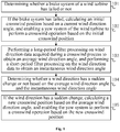
- Fig. 1 is a schematic flow chart of a control method for avoiding a wind turbine run-away according to an embodiment of the present disclosure. As shown in Fig. 1 , the control method for avoiding a wind turbine run-away may include steps 101 to 105.
- step 101 whether a brake system of the wind turbine has failed or not is determined.
- whether the brake system of the wind turbine has failed or not is determined by determining whether the brake system brakes at least two blades to a corresponding predetermined position within a first predetermined time period t1 after receiving a shutdown instruction. It is determined that the brake system has failed, if the brake system fails to brake the at least two blades to the corresponding predetermined position within the first predetermined time period t1 after receiving the shutdown instruction.
- the predetermined position may refer to a variable-pitch brake position
- variable-pitch braking may refer to perform a feathering operation along a plane parallel with a plane of a wind wheel to adjust a position of a blade from a windward surface to a position where an angle between the position and the plane of the wind wheel is 90°, so as to reduce the ability of capturing wind energy.
- whether the brake system of the wind turbine has failed or not may also be determined by determining whether the brake system reduces a rotating speed of the wind turbine to a predetermined rotating speed within a second predetermined time period t2 after receiving the shutdown instruction. It is determined that the brake system has failed, if the brake system fails to reduce the rotating speed of the wind turbine to the predetermined rotating speed within the second predetermined time period t2 after receiving the shutdown instruction.
- step 102 if the brake system has failed, an initial crosswind position is calculated based on a current wind direction angle, and a yaw system of the wind turbine is enabled to perform a crosswind operation based on the initial crosswind position.
- a crosswind position is a relative concept, and is determined based on the wind direction, that is, the crosswind position may change as the wind direction changes.
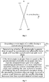
- Fig. 2 is a schematic diagram of a Cartesian coordinate system in which a wind direction is reference 0° according to an embodiment of the present disclosure, wherein the wind direction is represented by B.
- an angle range of [80°, 100°] and [260°, 280°] with respect to the wind direction B is used as the crosswind position range defined by the current wind direction B, even if the angle between the nacelle direction and the wind direction B is within [80, 100] and [260, 280].
- the crosswind position may also be obtained based on a method of simulating a running load of the impeller.
- step 103 a long-period filter processing is performed on wind direction data acquired during a crosswind process to obtain an average wind direction angle, and a short-period filter processing is performed on the wind direction data to obtain an instantaneous wind direction angle.
- the long-period filtering processing is suitable for yawing in a case of a relatively stable wind direction.
- the long-period filter processing is performed on the acquired wind direction data based on a weighting strategy of 30 s.
- the short-period filtering processing is used for a sudden change detection in the wind direction.
- the short-period filter processing is performed on the acquired wind direction data based on a weighting strategy of 5 s.
- Weighting-strategy based filter processing methods may refer to the prior art, and details will not be described herein.
- step 104 whether the wind direction has a sudden change or not is determined based on the average wind direction angle and the instantaneous wind direction angle.
- a difference between the average wind direction angle and the instantaneous wind direction angle is calculated. It is determined that the wind direction has a sudden change if the difference is greater than a preset threshold, and it is determined that the wind direction is relatively stable if the difference is not greater than the preset threshold.
- the average wind direction angle or the instantaneous wind direction angle may also be optimized (for example, by multiplying by some constants or performing some common data processing) based on an actual situation, so that the calculated average wind direction angle and instantaneous wind direction angle is used to accurately determine a sudden change in the wind direction.
- step 105 if the wind direction has a sudden change, a new crosswind position is calculated based on the average wind direction angle, and the yaw system is enabled to perform a crosswind operation based on the new crosswind position.
- a brake system of a wind turbine in order to avoid the occurrence of a run-away failure, whether a brake system of a wind turbine has failed or not is determined first. If the braking system has failed, an initial crosswind position is calculated based on a current wind direction angle, so that a yaw system of the wind turbine may perform a crosswind operation based on the initial crosswind position. Since the captured wind energy can be reduced after performing the crosswind operation, and thus rotating speed of the wind turbine can be reduced, therefore occurrence of a run-away failure can be avoided.
- the crosswind operation can be kept consistent with the wind direction. For example, when the wind direction changes greatly, the crosswind operation of the yaw system can be adjusted in time to improve the wind direction response rate and environmental adaptability of the yaw system.
- the control method for avoiding a wind turbine run-away in the embodiments of the present disclosure can actively determine whether the brake system of the wind turbine has failed, and can automatically enter into a crosswind process based on the determination result. Therefore, compared to triggering the crosswind operation of the yaw system artificially, on one hand, the control method for avoiding a wind turbine run-away has advantages of high timeliness and high accuracy. On the other hand, it can avoid occupational health risks to a maintenance personnel, especially being capable of performing automatic nighttime maintenance in place of a human. As such, it is ensured that a crosswind function is complete on a long-term basis, thereby preventing a crosswind failure caused by factors such as twisted cables, slow changes in the wind direction and sudden changes in the wind direction.
- control method for avoiding a wind turbine run-away in embodiments of the present disclosure does not need to add a new hardware device, and may adopt an implementation manner of a software control strategy, and thus the method has advantages of low cost and being easy to popularize.
- the cable may twist with the yaw system relative to its straight state, for example, one or more turns. Therefore, the yaw system should also meet a risk avoidance requirement for a twisted cable when performing a crosswind operation.
- an unwinding direction of the cable may also be acquired, and the yaw system is enabled to perform the crosswind operation along the unwinding direction to adjust the nacelle direction to the initial crosswind position, to reserve more twistable angles for the cable during a continuous crosswind process.
- the unwinding direction should be counterclockwise, and if the twist direction of the cable is counterclockwise, then the unwinding direction should be clockwise.
- Fig. 3 is a schematic flow chart of a control method for avoiding a wind turbine run-away according to another embodiment of the present disclosure.
- the control method for avoiding a wind turbine run-away may further include steps 301 to 305, for protecting a cable in a case where the yaw system continuously performs a crosswind operation, so as to avoid a wind turbine fault caused by an over-limit of a twist angle of the cable.
- step 301 the twist angle of the cable is acquired during a current crosswind process.
- step 302 whether the twist angle is greater than or equal to a predetermined allowable twist angle and less than a predetermined safe twist angle is determined.
- step 303 if the twist angle is greater than or equal to the predetermined allowable twist angle and less than the predetermined safe twist angle, performance of a next crosswind operation is suspended after the current crosswind process ends, and the yaw system is enabled to resume performing the next crosswind operation along the unwinding direction of the cable when an angle between a current wind direction and the nacelle direction becomes less than a predetermined critical angle.
- Each crosswind position may correspond to one crosswind operation. If the twist angle is greater than or equal to the predetermined allowable twist angle and less than the predetermined safe twist angle, it may indicate that after performing a crosswind operation by the yaw system, the allowable twist angle of the cable has been reached, but the safe twist angle of the cable (i.e., a twisted cable protection value which is set by a safety system of the wind turbine) has not been exceeded.
- the predetermined allowable twist angle and less than the predetermined safe twist angle it may indicate that after performing a crosswind operation by the yaw system, the allowable twist angle of the cable has been reached, but the safe twist angle of the cable (i.e., a twisted cable protection value which is set by a safety system of the wind turbine) has not been exceeded.
- the twist angle of the cable is an absolute concept.
- a position wherein the cable is in a straight state is considered as reference 0°, and the position of the reference 0° is determined by a lifting process of the wind turbine.
- the predetermined allowable twist angle is set to 800°
- the predetermined safe twist angle is set to 900°.
- Those skilled in the art may set a suitable predetermined allowable twist angle and a predetermined safe twist angle based on an actual situation, and there is no limit herein in this aspect.
- an angle between the wind direction and the nacelle direction when the rotating speed of the wind turbine is accelerating is considered as a predetermined critical angle. Since when the angle between the current wind direction and the nacelle direction is less than the predetermined critical angle, the impeller of the wind turbine is in a windward state, and thus the ability of capturing wind energy is strong, which may easily cause the rotating speed of the wind turbine to accelerate. Therefore, the yaw system is enabled to resume performing the next crosswind operation along the current unwinding direction, so as to prevent the wind turbine from causing a run-away failure due to the acceleration of the rotating speed.
- control method for avoiding a wind turbine run-away in embodiments of the present disclosure may further include the following contents.
- the yaw system receives other automatic yaw instructions that are not related to a crosswind operation during the current crosswind process, the other automatic yaw instructions that are not related to the crosswind operation is disabled, and the yaw system is controlled to continue to perform a current crosswind operation.
- the yaw system receives a manual yaw instruction during the current crosswind process, the current crosswind operation is terminated, and the yaw system is controlled to perform the next crosswind operation based on the manual yaw instruction.
- the manual yaw instruction is a manual local yaw instruction or a remote yaw instruction, and the difference between them is in that the sender is different.
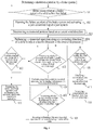
- Fig. 4 is a schematic flow chart of a control method for avoiding a wind turbine run-away according to yet another embodiment of the present disclosure, which is used to illustrate the control method for avoiding a wind turbine run-away in embodiments of the present disclosure in detail by means of an example.
- the control method for avoiding a wind turbine run-away in this example may include steps 401 to 413.
- step 401 whether a brake system of the wind turbine has failed or not is determined. If the brake system of the wind turbine has failed, then the method may proceed to step 402, and if the brake system of the wind turbine has not failed, then the method may return back to step 401.
- step 402 the failure accident of the brake system is alarmed and a yaw crosswind flag of a yaw system is activated.
- the alarm information and the activation information of the yaw crosswind flag is uploaded to a remote monitoring system.
- step 403 a crosswind position is determined based on a current wind direction.
- step 404 a crosswind operation is performed along an unwinding direction of a cable to adjust a nacelle direction to the crosswind position.
- step 405 whether a twist angle of the cable is greater than or equal to a predetermined allowable twist angle and less than a predetermined safe twist angle is determined. If the twist angle of the cable is greater than or equal to the predetermined allowable twist angle and less than the predetermined safe twist angle, then the method may proceed to step 406, otherwise, the method may return back to step 405.
- step 406 performance of a current crosswind operation is continued, and performance of a next crosswind operation is suspended.
- step 407 whether an angle between a wind direction and the nacelle direction is less than a predetermined critical angle is determined. If the angle between the wind direction and the nacelle direction is less than the predetermined critical angle, then the method may proceed to step 408, and if the angle between the wind direction and the nacelle direction is not less than the predetermined critical angle, then the method may return back to step 407.
- step 408 performance of the next crosswind operation is resumed in a current unwinding direction of the cable.
- step 409 whether the wind direction has a sudden change or not during a crosswind process is determined. If the wind direction has a sudden change during the crosswind process, then the method may proceed to step 410, and if the wind direction does not have a sudden change during the crosswind process, then the method may proceed to step 411.
- step 410 a crosswind position is calculated based on an average wind direction angle, and then the method may turn to step 404.
- step 411 a crosswind position is calculated using an instantaneous wind direction angle, and then the method may turn to step 404.
- step 412 whether a manual yaw instruction is received during the crosswind process is determined. If a manual yaw instruction is received during the crosswind process, then the method may proceed to step 413, and if no manual yaw instruction is received during the crosswind process, then the method may return back to step 405.
- step 413 the current crosswind operation is terminated, and a yaw operation is performed based on the manual yaw instruction.
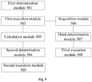
- Fig. 5 is a schematic structural diagram of a control device for avoiding a wind turbine run-away according to an embodiment of the present disclosure.
- the control device for avoiding a wind turbine run-away may include a first determination module 501, a first execution module 502, a calculation module 503, a second determination module 504 and a second execution module 505.
- the first determination module 501 is configured to determine whether a brake system of the wind turbine has failed or not.
- the first execution module 502 is configured to: if the brake system has failed, calculate an initial crosswind position based on a current wind direction angle, and enable a yaw system of the wind turbine to perform a crosswind operation based on the initial crosswind position.
- the first execution module 502 may include an acquisition unit and an execution unit.
- the acquisition unit is configured to obtain an unwinding direction of a cable.
- the execution unit is configured to enable the yaw system to perform the crosswind operation along the unwinding direction to adjust a nacelle direction to the initial crosswind position.
- the calculation module 503 is configured to: perform a long-period filter processing on wind direction data acquired during a crosswind process to obtain an average wind direction angle, and perform a short-period filter processing on the wind direction data to obtain an instantaneous wind direction angle.
- the second determination module 504 is configured to determine whether a wind direction has a sudden change or not based on the average wind direction angle and the instantaneous wind direction angle.
- the second determination module 504 may include a calculation unit and a determination unit.
- the calculation unit is configured to calculate a difference between the average wind direction angle and the instantaneous wind direction angle.
- the determination unit is configured to determine that the wind direction has a sudden change if the difference is greater than a preset threshold.
- the second execution module 505 is configured to: if the wind direction has a sudden change, calculate a new crosswind position based on the average wind direction angle, and enable the yaw system to perform a crosswind operation based on the new crosswind position.
- control device for avoiding a wind turbine run-away may further include an acquisition module 506, a third determination module 507 and a third execution module 508.
- the acquisition module 506 is configured to obtain a twist angle of the cable during a current crosswind process.
- the third determination module 507 is configured to determine whether the twist angle is greater than or equal to a predetermined allowable twist angle and less than a predetermined safe twist angle.
- the third execution module 508 is configured to: if the twist angle is greater than or equal to the predetermined allowable twist angle and less than the predetermined safe twist angle, suspend performance of a next crosswind operation after the current crosswind process ends, and enable the yaw system to resume performing the next crosswind operation along the unwinding direction of the cable when an angle between a current wind direction and the nacelle direction becomes less than a predetermined critical angle.
- control device for avoiding a wind turbine run-away described above is integrated into a main controller of the wind turbine, or is a component capable of performing logic operation independently, and there is no limit herein in this aspect.
- Embodiments of the present disclosure may also provide a wind turbine, which may include the control device for avoiding a wind turbine run-away described above.
- Examples of a machine-readable medium may include an electronic circuit, a semiconductor memory device, a ROM, a flash memory, an erasable ROM (EROM), a floppy disk, a CD-ROM, an optical disk, a hard disk, a fiber optic medium, a radio frequency (RF) link, and the like.
- the code segment is downloaded via a computer network such as the Internet, an intranet, and the like.
Landscapes
- Engineering & Computer Science (AREA)
- Life Sciences & Earth Sciences (AREA)
- Sustainable Development (AREA)
- Sustainable Energy (AREA)
- Chemical & Material Sciences (AREA)
- Combustion & Propulsion (AREA)
- Mechanical Engineering (AREA)
- General Engineering & Computer Science (AREA)
- Physics & Mathematics (AREA)
- Fluid Mechanics (AREA)
- Wind Motors (AREA)
- Steering Control In Accordance With Driving Conditions (AREA)
Claims (12)
- Steuerungsverfahren zur Vermeidung eines Windturbinendurchlaufs, umfassend:Feststellen, ob ein Bremssystem der Windturbine ausgefallen ist oder nicht;falls das Bremssystem ausgefallen ist, Berechnen einer anfänglichen Seitenwindposition auf Grundlage eines aktuellen Windrichtungswinkels und Aktivieren eines Giersystems der Windturbine zur Durchführung eines Seitenwindbetriebs auf Grundlage der anfänglichen Seitenwindposition;Durchführen einer Langzeitfilterverarbeitung zu Windrichtungsdaten, die während eines Seitenwindprozesses erfasst wurden, um einen durchschnittlichen Windrichtungswinkel zu erhalten, und Durchführen einer Kurzzeitfilterverarbeitung zu den Windrichtungsdaten, um einen momentanen Windrichtungswinkel zu erhalten;Feststellen, ob eine Windrichtung eine plötzliche Veränderung aufweist oder nicht, auf Grundlage des durchschnittlichen Windrichtungswinkels und des momentanen Windrichtungswinkels; undfalls die Windrichtung eine plötzliche Veränderung aufweist, Berechnen einer neuen Seitenwindposition auf Grundlage des durchschnittlichen Windrichtungswinkels und Aktivieren des Giersystems zur Durchführung eines Seitenwindbetriebs auf Grundlage der neuen Seitenwindposition.
- Verfahren nach Anspruch 1, wobei das Feststellen, ob die Windrichtung eine plötzliche Veränderung aufweist, auf Grundlage des durchschnittlichen Windrichtungswinkels und des momentanen Windrichtungswinkels Folgendes umfasst:Berechnen einer Differenz zwischen dem durchschnittlichen Windrichtungswinkel und dem momentanen Windrichtungswinkel; undFeststellen, dass die Windrichtung eine plötzliche Veränderung aufweist, falls die Differenz größer als ein vorgegebener Schwellenwert ist.
- Verfahren nach Anspruch 1, wobei ein Kabel in einem Maschinenhausraum der Windturbine angeordnet ist und das Aktivieren des Giersystems der Windturbine zur Durchführung eines Seitenwindbetriebs auf Grundlage der anfänglichen Seitenwindposition Folgendes umfasst:Erfassen einer Abwicklungsrichtung des Kabels; undAktivieren des Giersystems, um den Seitenwindbetrieb entlang der Abwicklungsrichtung auszuführen, um eine Maschinenhausrichtung auf die anfängliche Seitenwindposition einzustellen.
- Verfahren nach Anspruch 3, wobei das Verfahren ferner Folgendes umfasst:Erfassen eines Verdrehungswinkels des Kabels während eines aktuellen Seitenwindprozesses;Feststellen, ob der Verdrehungswinkel größer als oder gleich groß wie ein vorbestimmter zulässiger Verdrehungswinkel und kleiner als ein vorbestimmter sicherer Verdrehungswinkel ist;falls der Verdrehungswinkel größer als oder gleich groß wie der vorbestimmte zulässige Verdrehungswinkel und kleiner als der vorbestimmte sichere Verdrehungswinkel ist, Aussetzen der Durchführung eines nächsten Seitenwindbetriebs nach dem Ende des aktuellen Seitenwindprozesses und Aktivieren des Giersystems, um die Durchführung des nächsten Seitenwindbetriebs entlang der Abwicklungsrichtung des Kabels wiederaufzunehmen, falls ein Winkel zwischen einer aktuellen Windrichtung und der Maschinenhausrichtung kleiner als ein vorbestimmter kritischer Winkel wird.
- Verfahren nach Anspruch 1, wobei das Feststellen, ob das Bremssystem der Windturbine ausgefallen ist oder nicht, Folgendes umfasst:Feststellen, ob das Bremssystem innerhalb eines ersten vorbestimmten Zeitraums nach dem Empfang einer Abschaltanweisung mindestens zwei Blätter auf eine entsprechende vorbestimmte Position abbremst, undFeststellen, dass das Bremssystem ausgefallen ist, falls das Bremssystem die mindestens zwei Blätter innerhalb des ersten vorbestimmten Zeitraums nach dem Empfang der Abschaltanweisung nicht auf die entsprechende vorbestimmte Position abbremst; oderFeststellen, ob das Bremssystem eine Drehgeschwindigkeit der Windturbine innerhalb eines zweiten vorbestimmten Zeitraums nach dem Empfang der Abschaltanweisung auf eine vorbestimmte Drehgeschwindigkeit reduziert, undFeststellen, dass das Bremssystem ausgefallen ist, falls das Bremssystem die Drehgeschwindigkeit der Windturbine innerhalb des zweiten vorbestimmten Zeitraums nach dem Empfang der Abschaltanweisung nicht auf die vorbestimmte Drehgeschwindigkeit reduziert.
- Verfahren nach Anspruch 1, wobei das Verfahren ferner Folgendes umfasst:falls das Giersystem während eines aktuellen Seitenwindprozesses andere automatische Gieranweisungen empfängt, die sich nicht auf einen Seitenwindbetrieb beziehen, Deaktivieren der anderen automatischen Gieranweisungen, die sich nicht auf den Seitenwindbetrieb beziehen, und Steuern des Giersystems, um damit fortzufahren, einen aktuellen Seitenwindbetrieb durchzuführen;falls das Giersystem während des aktuellen Seitenwindprozesses eine manuelle Gieranweisung empfängt, Beenden des aktuellen Seitenwindbetriebs und Steuern des Giersystems, um einen nächsten Seitenwindbetrieb auf Grundlage der manuellen Gieranweisung durchzuführen.
- Steuerungsvorrichtung zur Vermeidung eines Windturbinendurchlaufs, umfassend:ein erstes Feststellungsmodul, das dazu ausgestaltet ist, festzustellen, ob ein Bremssystem der Windturbine ausgefallen ist oder nicht;ein erstes Ausführungsmodul, das für Folgendes ausgestaltet ist: falls das Bremssystem ausgefallen ist, Berechnen einer anfänglichen Seitenwindposition auf Grundlage eines aktuellen Windrichtungswinkels und Aktivieren eines Giersystems der Windturbine, um einen Seitenwindbetrieb auf Grundlage der anfänglichen Seitenwindposition durchzuführen;ein Kalkulationsmodul, das für Folgendes ausgestaltet ist: Durchführen einer langfristigen Filterverarbeitung zu Windrichtungsdaten, die während eines Seitenwindprozesses erfasst wurden, um einen durchschnittlichen Windrichtungswinkel zu erhalten, und Durchführen einer kurzfristigen Filterverarbeitung zu den Windrichtungsdaten, um einen momentanen Windrichtungswinkel zu erhalten;ein zweites Feststellungsmodul, das dazu ausgestaltet ist, auf Grundlage des durchschnittlichen Windrichtungswinkels und des momentanen Windrichtungswinkels festzustellen, ob eine Windrichtung eine plötzliche Veränderung aufweist oder nicht; undein zweites Ausführungsmodul, das für Folgendes ausgestaltet ist: falls die Windrichtung eine plötzliche Veränderung aufweist, Berechnen einer neuen Seitenwindposition auf Grundlage des durchschnittlichen Windrichtungswinkels und Aktivieren des Giersystems zur Durchführung eines Seitenwindbetriebs auf Grundlage der neuen Seitenwindposition.
- Vorrichtung nach Anspruch 7, wobei das zweite Feststellungsmodul Folgendes umfasst:eine Berechnungseinheit, die dazu ausgestaltet ist, eine Differenz zwischen dem durchschnittlichen Windrichtungswinkel und dem momentanen Windrichtungswinkel zu berechnen; undeine Feststellungseinheit, die dazu ausgestaltet ist, festzustellen, dass die Windrichtung eine plötzliche Veränderung aufweist, falls die Differenz größer als ein vorgegebener Schwellenwert ist.
- Vorrichtung nach Anspruch 7, wobei ein Kabel in einem Maschinenhausraum der Windturbine angeordnet ist und das erste Ausführungsmodul Folgendes umfasst:eine Erfassungseinheit, die dazu ausgestaltet ist, eine Abwicklungsrichtung des Kabels zu erfassen;eine Ausführungseinheit, die dazu ausgestaltet ist, das Giersystem zu aktivieren, um den Seitenwindbetrieb entlang der Abwicklungsrichtung auszuführen, um eine Maschinenhausrichtung auf die anfängliche Seitenwindposition einzustellen.
- Vorrichtung nach Anspruch 9, wobei die Vorrichtung ferner Folgendes umfasst:ein Erfassungsmodul, das dazu ausgestaltet ist, einen Verdrehungswinkel des Kabels während eines aktuellen Seitenwindprozesses zu erfassen;ein drittes Feststellungsmodul, das dazu ausgestaltet ist, festzustellen, ob der Verdrehungswinkel größer als oder gleich groß wie ein vorbestimmter zulässiger Verdrehungswinkel und kleiner als ein vorbestimmter sicherer Verdrehungswinkel ist;ein drittes Ausführungsmodul, das für Folgendes ausgestaltet ist: falls der Verdrehungswinkel größer als oder gleich groß wie der vorbestimmte zulässige Verdrehungswinkel und kleiner als der vorbestimmte sichere Verdrehungswinkel ist, Aussetzen der Durchführung eines nächsten Seitenwindbetriebs nach dem Ende des aktuellen Seitenwindprozesses und Aktivieren des Giersystems, um die Durchführung des nächsten Seitenwindbetriebs entlang der Abwicklungsrichtung des Kabels wiederaufzunehmen, falls ein Winkel zwischen einer aktuellen Windrichtung und der Maschinenhausrichtung kleiner als ein vorbestimmter kritischer Winkel wird.
- Vorrichtung nach Anspruch 10, wobei die Vorrichtung in eine Hauptsteuerung der Windturbine integriert ist.
- Windturbine, umfassend die Steuerungsvorrichtung zur Vermeidung eines Windturbinendurchlaufs nach einem der Ansprüche 7-11.
Applications Claiming Priority (2)
| Application Number | Priority Date | Filing Date | Title |
|---|---|---|---|
| CN201810171876.0A CN108488037B (zh) | 2018-03-01 | 2018-03-01 | 防飞车控制方法和装置、风力发电机组 |
| PCT/CN2018/095302 WO2019165744A1 (zh) | 2018-03-01 | 2018-07-11 | 防飞车控制方法和装置、风力发电机组 |
Publications (4)
| Publication Number | Publication Date |
|---|---|
| EP3557047A1 EP3557047A1 (de) | 2019-10-23 |
| EP3557047A4 EP3557047A4 (de) | 2020-12-16 |
| EP3557047B1 true EP3557047B1 (de) | 2021-09-29 |
| EP3557047B8 EP3557047B8 (de) | 2021-12-15 |
Family
ID=63341142
Family Applications (1)
| Application Number | Title | Priority Date | Filing Date |
|---|---|---|---|
| EP18887198.2A Active EP3557047B8 (de) | 2018-03-01 | 2018-07-11 | Steuerungsverfahren zur vermeidung eines durchgehens der windturbine, entsprechende vorrichtung und windenergieanlage |
Country Status (6)
| Country | Link |
|---|---|
| US (1) | US11365716B2 (de) |
| EP (1) | EP3557047B8 (de) |
| CN (1) | CN108488037B (de) |
| AU (1) | AU2018386361B2 (de) |
| ES (1) | ES2899573T3 (de) |
| WO (1) | WO2019165744A1 (de) |
Families Citing this family (7)
| Publication number | Priority date | Publication date | Assignee | Title |
|---|---|---|---|---|
| CN110374800B (zh) * | 2019-06-06 | 2021-01-05 | 北京优利康达科技股份有限公司 | 一种防止风机失火和飞车的装置和控制方法 |
| CN112576453B (zh) * | 2020-11-12 | 2021-11-19 | 南京力思拓能源科技有限公司 | 一种基于多普勒激光雷达技术的风力发电机风速风向仪状态评估方法及系统 |
| CN112594131B (zh) * | 2020-11-26 | 2022-04-26 | 中国船舶重工集团海装风电股份有限公司 | 一种风力发电机组侧风偏航控制方法、系统及相关组件 |
| CN114718807A (zh) * | 2022-03-14 | 2022-07-08 | 上海电气风电集团股份有限公司 | 风电机组防超速方法及其系统及计算机可读存储介质 |
| CN114704438B (zh) * | 2022-06-02 | 2022-09-20 | 深圳众城卓越科技有限公司 | 风电机组故障监控方法及装置 |
| CN115405475B (zh) * | 2022-08-30 | 2025-06-27 | 三一重能股份有限公司 | 风力发电机组的偏航滑移识别方法、装置及风力发电机组 |
| CN115614220A (zh) * | 2022-09-08 | 2023-01-17 | 华能新能源股份有限公司河北分公司 | 一种风力发电机组侧风偏航控制系统、方法及发电机组 |
Family Cites Families (33)
| Publication number | Priority date | Publication date | Assignee | Title |
|---|---|---|---|---|
| US5278773A (en) * | 1990-09-10 | 1994-01-11 | Zond Systems Inc. | Control systems for controlling a wind turbine |
| CA2350745C (en) * | 1998-11-26 | 2003-11-11 | Aloys Wobben | Azimuthal driving system for wind turbines |
| DE10106208C2 (de) * | 2001-02-10 | 2002-12-19 | Aloys Wobben | Windenergieanlage |
| US20060275121A1 (en) * | 2003-04-17 | 2006-12-07 | Merswolka Paul H/F And Meyer Charles F | Wind turbine with friction drive power take off on outer rim |
| US20060153672A1 (en) * | 2003-04-24 | 2006-07-13 | Davis Dean A | Furling wind turbine |
| DE102006001613B4 (de) * | 2006-01-11 | 2008-01-31 | Repower Systems Ag | Verfahren zum Betreiben einer Windenergieanlage und Windenergieanlage |
| JP4939286B2 (ja) * | 2007-04-10 | 2012-05-23 | 三菱重工業株式会社 | 風力発電装置及びその制御方法 |
| JP2008309097A (ja) * | 2007-06-15 | 2008-12-25 | Ebara Corp | 風力発電設備及び風力発電用風車制御方法 |
| DE102007045437A1 (de) * | 2007-09-22 | 2009-04-02 | Nordex Energy Gmbh | Verfahren zur Steuerung einer Windenergieanlage |
| JP5199828B2 (ja) * | 2008-10-29 | 2013-05-15 | 三菱重工業株式会社 | 風力発電装置及びその制御方法 |
| US7786608B2 (en) * | 2008-11-17 | 2010-08-31 | General Electric Company | Protection system for wind turbine |
| JP5566609B2 (ja) * | 2009-01-05 | 2014-08-06 | 三菱重工業株式会社 | 風力発電装置及び風力発電装置の制御方法 |
| US20100209246A1 (en) * | 2009-02-13 | 2010-08-19 | Robert Migliori | Yaw controller for downwind wind turbines |
| WO2010130057A2 (en) * | 2009-05-15 | 2010-11-18 | Redriven Power Inc. | System and method for controlling a wind turbine |
| JP2011127551A (ja) * | 2009-12-18 | 2011-06-30 | Mitsubishi Heavy Ind Ltd | 風力発電装置 |
| EP2609326B1 (de) * | 2010-08-23 | 2017-06-21 | Vestas Wind Systems A/S | Verfahren zum betrieb einer windturbine und windturbine |
| GB2487715A (en) * | 2011-01-18 | 2012-08-08 | Vestas Wind Sys As | Method and apparatus for protecting wind turbines from extreme wind direction changes |
| CN102619688A (zh) * | 2012-04-18 | 2012-08-01 | 中船重工(重庆)海装风电设备有限公司 | 一种风力发电机组刹车制动控制装置及方法 |
| KR101346275B1 (ko) * | 2012-09-04 | 2014-01-03 | 삼성중공업 주식회사 | 케이블 꼬임이 방지되는 풍력 발전기의 요 운전 방법 |
| CN102828909B (zh) * | 2012-09-12 | 2014-04-02 | 国电联合动力技术有限公司 | 风电机组叶片收桨失效时的安全保护方法、装置及系统 |
| DE102012221289A1 (de) * | 2012-11-21 | 2014-05-22 | Repower Systems Se | Verfahren zum Betreiben einer Windenergieanlage und Windenergieanlage |
| CN103225586B (zh) * | 2013-04-26 | 2015-02-25 | 北京天诚同创电气有限公司 | 一种风力发电机组防飞车安全控制方法 |
| EP2860392B1 (de) | 2013-10-09 | 2018-03-07 | Siemens Aktiengesellschaft | Verfahren zur Einstellung des Windwinkels einer Windturbine in Bezug auf eine gegebene Windrichtung |
| CN104179636B (zh) * | 2014-07-25 | 2017-02-15 | 北车风电有限公司 | 一种防止风力发电机组飞车的方法 |
| CN104314759A (zh) * | 2014-10-23 | 2015-01-28 | 内蒙古久和能源科技有限公司 | 一种基于风向加权滤波的风力发电机组自动偏航控制方法 |
| JP6628983B2 (ja) * | 2015-06-02 | 2020-01-15 | ナブテスコ株式会社 | 風車用駆動装置及び風車用駆動装置ユニット |
| CN107514337B (zh) * | 2016-06-17 | 2019-08-09 | 北京天诚同创电气有限公司 | 风力发电机组的控制方法、装置及风电场群控系统 |
| CN205977543U (zh) * | 2016-06-29 | 2017-02-22 | 国电联合动力技术有限公司 | 一种风电机组防超速控制装置、偏航系统及风电机组 |
| CN107620670A (zh) * | 2016-07-13 | 2018-01-23 | 北京国电思达科技有限公司 | 一种风电机组防超速偏航控制方法 |
| CN109863299B (zh) * | 2016-10-07 | 2021-07-09 | 西门子歌美飒可再生能源公司 | 确定风力涡轮机塔架倾斜角 |
| CN107701372B (zh) * | 2017-10-18 | 2019-06-11 | 明阳智慧能源集团股份公司 | 一种变桨执行器失效下的风力发电机组自我保护控制方法 |
| CN110094296B (zh) * | 2018-01-29 | 2020-06-09 | 江苏金风科技有限公司 | 风力发电机组在台风下的偏航控制方法和装置 |
| US10364799B1 (en) * | 2018-02-09 | 2019-07-30 | Inventus Holdings, Llc | Secure windfarm power production during a SCADA system offline mode |
-
2018
- 2018-03-01 CN CN201810171876.0A patent/CN108488037B/zh active Active
- 2018-07-11 EP EP18887198.2A patent/EP3557047B8/de active Active
- 2018-07-11 ES ES18887198T patent/ES2899573T3/es active Active
- 2018-07-11 US US16/471,652 patent/US11365716B2/en active Active
- 2018-07-11 WO PCT/CN2018/095302 patent/WO2019165744A1/zh not_active Ceased
- 2018-07-11 AU AU2018386361A patent/AU2018386361B2/en active Active
Also Published As
| Publication number | Publication date |
|---|---|
| EP3557047A4 (de) | 2020-12-16 |
| CN108488037A (zh) | 2018-09-04 |
| US11365716B2 (en) | 2022-06-21 |
| AU2018386361B2 (en) | 2021-02-25 |
| ES2899573T3 (es) | 2022-03-14 |
| AU2018386361A1 (en) | 2019-09-19 |
| WO2019165744A1 (zh) | 2019-09-06 |
| EP3557047B8 (de) | 2021-12-15 |
| EP3557047A1 (de) | 2019-10-23 |
| CN108488037B (zh) | 2019-07-19 |
| US20210246873A1 (en) | 2021-08-12 |
Similar Documents
| Publication | Publication Date | Title |
|---|---|---|
| EP3557047B1 (de) | Steuerungsverfahren zur vermeidung eines durchgehens der windturbine, entsprechende vorrichtung und windenergieanlage | |
| JP5117677B2 (ja) | ウィンドファームならびにその制御方法 | |
| US8829699B2 (en) | Rotational speed control of a wind turbine based on rotor acceleration | |
| CN102828909B (zh) | 风电机组叶片收桨失效时的安全保护方法、装置及系统 | |
| CN209523844U (zh) | 变桨控制系统及风力发电机组 | |
| WO2011042369A2 (en) | Control method for a wind turbine | |
| EP3597910B1 (de) | System und verfahren zur reduzierung von lasten während eines leerlaufs oder im geparkten zustand einer windturbine mit einem festgefahrenen rotorblatt | |
| CN109989883B (zh) | 风力发电机组的控制方法、装置及系统 | |
| CA2787441C (en) | Wind energy plant having a blade heater | |
| CN112145344B (zh) | 风力发电机组的解缆控制方法和装置 | |
| CN105240214A (zh) | 一种用于风电机组超速保护的安全回路 | |
| CN112761874A (zh) | 安全停机方法、系统和风力发电机 | |
| CN110700997A (zh) | 一种风电变桨控制系统叶轮转速监测方法 | |
| CN115559853A (zh) | 一种消除风机叶片涡激振动方法、系统、介质及设备 | |
| CN117989057B (zh) | 考虑湍流风况的高山风电场偏航控制策略优化方法、装置、电子设备及计算机可读存储介质 | |
| CN112523942B (zh) | 一种保护塔筒扭转的控制方法 | |
| CN114718811B (zh) | 一种基于gps监测风机叶片状态的自适应控制方法 | |
| CN119467212B (zh) | 一种风电机组顺桨方法、装置、电子设备及存储介质 | |
| EP4592521A1 (de) | Verfahren und vorrichtung zur unterdrückung von windturbinenflattern sowie steuerungssystem und windturbine | |
| CN214660615U (zh) | 一种风电机组超速保护系统 | |
| KR20230155964A (ko) | 풍력 터빈 제어 | |
| CN111219294B (zh) | 风致振动的主动偏航缓解 | |
| CN209800161U (zh) | 一种具有主动安全顺桨功能的变桨系统 | |
| CN110296044A (zh) | 一种具有主动安全顺桨功能的变桨系统 | |
| EP4310322A1 (de) | Verfahren und system zur steuerung einer schwimmenden windturbine |
Legal Events
| Date | Code | Title | Description |
|---|---|---|---|
| STAA | Information on the status of an ep patent application or granted ep patent |
Free format text: STATUS: UNKNOWN |
|
| STAA | Information on the status of an ep patent application or granted ep patent |
Free format text: STATUS: THE INTERNATIONAL PUBLICATION HAS BEEN MADE |
|
| PUAI | Public reference made under article 153(3) epc to a published international application that has entered the european phase |
Free format text: ORIGINAL CODE: 0009012 |
|
| STAA | Information on the status of an ep patent application or granted ep patent |
Free format text: STATUS: REQUEST FOR EXAMINATION WAS MADE |
|
| 17P | Request for examination filed |
Effective date: 20190617 |
|
| AK | Designated contracting states |
Kind code of ref document: A1 Designated state(s): AL AT BE BG CH CY CZ DE DK EE ES FI FR GB GR HR HU IE IS IT LI LT LU LV MC MK MT NL NO PL PT RO RS SE SI SK SM TR |
|
| R17P | Request for examination filed (corrected) |
Effective date: 20190617 |
|
| A4 | Supplementary search report drawn up and despatched |
Effective date: 20201113 |
|
| RIC1 | Information provided on ipc code assigned before grant |
Ipc: F03D 7/04 20060101AFI20201109BHEP Ipc: F03D 7/02 20060101ALI20201109BHEP |
|
| GRAP | Despatch of communication of intention to grant a patent |
Free format text: ORIGINAL CODE: EPIDOSNIGR1 |
|
| STAA | Information on the status of an ep patent application or granted ep patent |
Free format text: STATUS: GRANT OF PATENT IS INTENDED |
|
| RIC1 | Information provided on ipc code assigned before grant |
Ipc: F03D 7/02 20060101ALI20210528BHEP Ipc: F03D 7/04 20060101AFI20210528BHEP |
|
| INTG | Intention to grant announced |
Effective date: 20210618 |
|
| GRAS | Grant fee paid |
Free format text: ORIGINAL CODE: EPIDOSNIGR3 |
|
| GRAA | (expected) grant |
Free format text: ORIGINAL CODE: 0009210 |
|
| STAA | Information on the status of an ep patent application or granted ep patent |
Free format text: STATUS: THE PATENT HAS BEEN GRANTED |
|
| AK | Designated contracting states |
Kind code of ref document: B1 Designated state(s): AL AT BE BG CH CY CZ DE DK EE ES FI FR GB GR HR HU IE IS IT LI LT LU LV MC MK MT NL NO PL PT RO RS SE SI SK SM TR |
|
| REG | Reference to a national code |
Ref country code: GB Ref legal event code: FG4D |
|
| REG | Reference to a national code |
Ref country code: CH Ref legal event code: EP Ref country code: AT Ref legal event code: REF Ref document number: 1434420 Country of ref document: AT Kind code of ref document: T Effective date: 20211015 |
|
| REG | Reference to a national code |
Ref country code: DE Ref legal event code: R096 Ref document number: 602018024460 Country of ref document: DE |
|
| REG | Reference to a national code |
Ref country code: IE Ref legal event code: FG4D |
|
| GRAT | Correction requested after decision to grant or after decision to maintain patent in amended form |
Free format text: ORIGINAL CODE: EPIDOSNCDEC |
|
| REG | Reference to a national code |
Ref country code: CH Ref legal event code: PK Free format text: BERICHTIGUNGEN |
|
| RIN2 | Information on inventor provided after grant (corrected) |
Inventor name: SUN, CHANGLIANG |
|
| REG | Reference to a national code |
Ref country code: GR Ref legal event code: EP Ref document number: 20210402862 Country of ref document: GR Effective date: 20211209 |
|
| REG | Reference to a national code |
Ref country code: LT Ref legal event code: MG9D |
|
| PG25 | Lapsed in a contracting state [announced via postgrant information from national office to epo] |
Ref country code: LT Free format text: LAPSE BECAUSE OF FAILURE TO SUBMIT A TRANSLATION OF THE DESCRIPTION OR TO PAY THE FEE WITHIN THE PRESCRIBED TIME-LIMIT Effective date: 20210929 Ref country code: BG Free format text: LAPSE BECAUSE OF FAILURE TO SUBMIT A TRANSLATION OF THE DESCRIPTION OR TO PAY THE FEE WITHIN THE PRESCRIBED TIME-LIMIT Effective date: 20211229 Ref country code: NO Free format text: LAPSE BECAUSE OF FAILURE TO SUBMIT A TRANSLATION OF THE DESCRIPTION OR TO PAY THE FEE WITHIN THE PRESCRIBED TIME-LIMIT Effective date: 20211229 Ref country code: HR Free format text: LAPSE BECAUSE OF FAILURE TO SUBMIT A TRANSLATION OF THE DESCRIPTION OR TO PAY THE FEE WITHIN THE PRESCRIBED TIME-LIMIT Effective date: 20210929 Ref country code: FI Free format text: LAPSE BECAUSE OF FAILURE TO SUBMIT A TRANSLATION OF THE DESCRIPTION OR TO PAY THE FEE WITHIN THE PRESCRIBED TIME-LIMIT Effective date: 20210929 Ref country code: SE Free format text: LAPSE BECAUSE OF FAILURE TO SUBMIT A TRANSLATION OF THE DESCRIPTION OR TO PAY THE FEE WITHIN THE PRESCRIBED TIME-LIMIT Effective date: 20210929 Ref country code: RS Free format text: LAPSE BECAUSE OF FAILURE TO SUBMIT A TRANSLATION OF THE DESCRIPTION OR TO PAY THE FEE WITHIN THE PRESCRIBED TIME-LIMIT Effective date: 20210929 |
|
| REG | Reference to a national code |
Ref country code: NL Ref legal event code: MP Effective date: 20210929 |
|
| REG | Reference to a national code |
Ref country code: AT Ref legal event code: MK05 Ref document number: 1434420 Country of ref document: AT Kind code of ref document: T Effective date: 20210929 |
|
| PG25 | Lapsed in a contracting state [announced via postgrant information from national office to epo] |
Ref country code: LV Free format text: LAPSE BECAUSE OF FAILURE TO SUBMIT A TRANSLATION OF THE DESCRIPTION OR TO PAY THE FEE WITHIN THE PRESCRIBED TIME-LIMIT Effective date: 20210929 |
|
| REG | Reference to a national code |
Ref country code: ES Ref legal event code: FG2A Ref document number: 2899573 Country of ref document: ES Kind code of ref document: T3 Effective date: 20220314 |
|
| PG25 | Lapsed in a contracting state [announced via postgrant information from national office to epo] |
Ref country code: AT Free format text: LAPSE BECAUSE OF FAILURE TO SUBMIT A TRANSLATION OF THE DESCRIPTION OR TO PAY THE FEE WITHIN THE PRESCRIBED TIME-LIMIT Effective date: 20210929 |
|
| PG25 | Lapsed in a contracting state [announced via postgrant information from national office to epo] |
Ref country code: IS Free format text: LAPSE BECAUSE OF FAILURE TO SUBMIT A TRANSLATION OF THE DESCRIPTION OR TO PAY THE FEE WITHIN THE PRESCRIBED TIME-LIMIT Effective date: 20220129 Ref country code: SK Free format text: LAPSE BECAUSE OF FAILURE TO SUBMIT A TRANSLATION OF THE DESCRIPTION OR TO PAY THE FEE WITHIN THE PRESCRIBED TIME-LIMIT Effective date: 20210929 Ref country code: RO Free format text: LAPSE BECAUSE OF FAILURE TO SUBMIT A TRANSLATION OF THE DESCRIPTION OR TO PAY THE FEE WITHIN THE PRESCRIBED TIME-LIMIT Effective date: 20210929 Ref country code: PT Free format text: LAPSE BECAUSE OF FAILURE TO SUBMIT A TRANSLATION OF THE DESCRIPTION OR TO PAY THE FEE WITHIN THE PRESCRIBED TIME-LIMIT Effective date: 20220131 Ref country code: PL Free format text: LAPSE BECAUSE OF FAILURE TO SUBMIT A TRANSLATION OF THE DESCRIPTION OR TO PAY THE FEE WITHIN THE PRESCRIBED TIME-LIMIT Effective date: 20210929 Ref country code: NL Free format text: LAPSE BECAUSE OF FAILURE TO SUBMIT A TRANSLATION OF THE DESCRIPTION OR TO PAY THE FEE WITHIN THE PRESCRIBED TIME-LIMIT Effective date: 20210929 Ref country code: EE Free format text: LAPSE BECAUSE OF FAILURE TO SUBMIT A TRANSLATION OF THE DESCRIPTION OR TO PAY THE FEE WITHIN THE PRESCRIBED TIME-LIMIT Effective date: 20210929 Ref country code: AL Free format text: LAPSE BECAUSE OF FAILURE TO SUBMIT A TRANSLATION OF THE DESCRIPTION OR TO PAY THE FEE WITHIN THE PRESCRIBED TIME-LIMIT Effective date: 20210929 |
|
| REG | Reference to a national code |
Ref country code: DE Ref legal event code: R097 Ref document number: 602018024460 Country of ref document: DE |
|
| PG25 | Lapsed in a contracting state [announced via postgrant information from national office to epo] |
Ref country code: DK Free format text: LAPSE BECAUSE OF FAILURE TO SUBMIT A TRANSLATION OF THE DESCRIPTION OR TO PAY THE FEE WITHIN THE PRESCRIBED TIME-LIMIT Effective date: 20210929 Ref country code: CZ Free format text: LAPSE BECAUSE OF FAILURE TO SUBMIT A TRANSLATION OF THE DESCRIPTION OR TO PAY THE FEE WITHIN THE PRESCRIBED TIME-LIMIT Effective date: 20210929 |
|
| PLBE | No opposition filed within time limit |
Free format text: ORIGINAL CODE: 0009261 |
|
| STAA | Information on the status of an ep patent application or granted ep patent |
Free format text: STATUS: NO OPPOSITION FILED WITHIN TIME LIMIT |
|
| 26N | No opposition filed |
Effective date: 20220630 |
|
| PG25 | Lapsed in a contracting state [announced via postgrant information from national office to epo] |
Ref country code: SI Free format text: LAPSE BECAUSE OF FAILURE TO SUBMIT A TRANSLATION OF THE DESCRIPTION OR TO PAY THE FEE WITHIN THE PRESCRIBED TIME-LIMIT Effective date: 20210929 |
|
| REG | Reference to a national code |
Ref country code: DE Ref legal event code: R119 Ref document number: 602018024460 Country of ref document: DE |
|
| PG25 | Lapsed in a contracting state [announced via postgrant information from national office to epo] |
Ref country code: MC Free format text: LAPSE BECAUSE OF FAILURE TO SUBMIT A TRANSLATION OF THE DESCRIPTION OR TO PAY THE FEE WITHIN THE PRESCRIBED TIME-LIMIT Effective date: 20210929 |
|
| REG | Reference to a national code |
Ref country code: CH Ref legal event code: PL |
|
| GBPC | Gb: european patent ceased through non-payment of renewal fee |
Effective date: 20220711 |
|
| REG | Reference to a national code |
Ref country code: BE Ref legal event code: MM Effective date: 20220731 |
|
| PG25 | Lapsed in a contracting state [announced via postgrant information from national office to epo] |
Ref country code: LU Free format text: LAPSE BECAUSE OF NON-PAYMENT OF DUE FEES Effective date: 20220711 Ref country code: LI Free format text: LAPSE BECAUSE OF NON-PAYMENT OF DUE FEES Effective date: 20220731 Ref country code: FR Free format text: LAPSE BECAUSE OF NON-PAYMENT OF DUE FEES Effective date: 20220731 Ref country code: CH Free format text: LAPSE BECAUSE OF NON-PAYMENT OF DUE FEES Effective date: 20220731 |
|
| PG25 | Lapsed in a contracting state [announced via postgrant information from national office to epo] |
Ref country code: GB Free format text: LAPSE BECAUSE OF NON-PAYMENT OF DUE FEES Effective date: 20220711 Ref country code: DE Free format text: LAPSE BECAUSE OF NON-PAYMENT OF DUE FEES Effective date: 20230201 Ref country code: BE Free format text: LAPSE BECAUSE OF NON-PAYMENT OF DUE FEES Effective date: 20220731 |
|
| P01 | Opt-out of the competence of the unified patent court (upc) registered |
Effective date: 20230411 |
|
| PG25 | Lapsed in a contracting state [announced via postgrant information from national office to epo] |
Ref country code: IE Free format text: LAPSE BECAUSE OF NON-PAYMENT OF DUE FEES Effective date: 20220711 |
|
| PG25 | Lapsed in a contracting state [announced via postgrant information from national office to epo] |
Ref country code: HU Free format text: LAPSE BECAUSE OF FAILURE TO SUBMIT A TRANSLATION OF THE DESCRIPTION OR TO PAY THE FEE WITHIN THE PRESCRIBED TIME-LIMIT; INVALID AB INITIO Effective date: 20180711 |
|
| PG25 | Lapsed in a contracting state [announced via postgrant information from national office to epo] |
Ref country code: SM Free format text: LAPSE BECAUSE OF FAILURE TO SUBMIT A TRANSLATION OF THE DESCRIPTION OR TO PAY THE FEE WITHIN THE PRESCRIBED TIME-LIMIT Effective date: 20210929 Ref country code: MK Free format text: LAPSE BECAUSE OF FAILURE TO SUBMIT A TRANSLATION OF THE DESCRIPTION OR TO PAY THE FEE WITHIN THE PRESCRIBED TIME-LIMIT Effective date: 20210929 Ref country code: CY Free format text: LAPSE BECAUSE OF FAILURE TO SUBMIT A TRANSLATION OF THE DESCRIPTION OR TO PAY THE FEE WITHIN THE PRESCRIBED TIME-LIMIT Effective date: 20210929 |
|
| PG25 | Lapsed in a contracting state [announced via postgrant information from national office to epo] |
Ref country code: MT Free format text: LAPSE BECAUSE OF FAILURE TO SUBMIT A TRANSLATION OF THE DESCRIPTION OR TO PAY THE FEE WITHIN THE PRESCRIBED TIME-LIMIT Effective date: 20210929 |
|
| PGFP | Annual fee paid to national office [announced via postgrant information from national office to epo] |
Ref country code: GR Payment date: 20250618 Year of fee payment: 8 |
|
| PGFP | Annual fee paid to national office [announced via postgrant information from national office to epo] |
Ref country code: ES Payment date: 20250804 Year of fee payment: 8 |
|
| PGFP | Annual fee paid to national office [announced via postgrant information from national office to epo] |
Ref country code: TR Payment date: 20250703 Year of fee payment: 8 Ref country code: IT Payment date: 20250623 Year of fee payment: 8 |