EP3557047B1 - Control method and device for avoiding run-away and wind turbine - Google Patents
Control method and device for avoiding run-away and wind turbine Download PDFInfo
- Publication number
- EP3557047B1 EP3557047B1 EP18887198.2A EP18887198A EP3557047B1 EP 3557047 B1 EP3557047 B1 EP 3557047B1 EP 18887198 A EP18887198 A EP 18887198A EP 3557047 B1 EP3557047 B1 EP 3557047B1
- Authority
- EP
- European Patent Office
- Prior art keywords
- crosswind
- wind direction
- angle
- wind turbine
- wind
- Prior art date
- Legal status (The legal status is an assumption and is not a legal conclusion. Google has not performed a legal analysis and makes no representation as to the accuracy of the status listed.)
- Active
Links
- 238000000034 method Methods 0.000 title claims description 81
- 230000008569 process Effects 0.000 claims description 33
- 230000008859 change Effects 0.000 claims description 27
- 238000012545 processing Methods 0.000 claims description 22
- 238000010586 diagram Methods 0.000 description 5
- 238000012423 maintenance Methods 0.000 description 5
- 230000006870 function Effects 0.000 description 4
- 230000007613 environmental effect Effects 0.000 description 3
- 238000001914 filtration Methods 0.000 description 3
- 238000010248 power generation Methods 0.000 description 3
- 230000005540 biological transmission Effects 0.000 description 2
- 238000001514 detection method Methods 0.000 description 2
- 230000036541 health Effects 0.000 description 2
- 230000007774 longterm Effects 0.000 description 2
- 230000004044 response Effects 0.000 description 2
- 230000001133 acceleration Effects 0.000 description 1
- 230000004913 activation Effects 0.000 description 1
- 238000004891 communication Methods 0.000 description 1
- 238000013016 damping Methods 0.000 description 1
- 230000007123 defense Effects 0.000 description 1
- 230000000694 effects Effects 0.000 description 1
- 238000005516 engineering process Methods 0.000 description 1
- 239000000835 fiber Substances 0.000 description 1
- 238000005461 lubrication Methods 0.000 description 1
- 230000007246 mechanism Effects 0.000 description 1
- 238000012544 monitoring process Methods 0.000 description 1
- 230000003287 optical effect Effects 0.000 description 1
- 238000003672 processing method Methods 0.000 description 1
- 239000004065 semiconductor Substances 0.000 description 1
Images
Classifications
-
- F—MECHANICAL ENGINEERING; LIGHTING; HEATING; WEAPONS; BLASTING
- F03—MACHINES OR ENGINES FOR LIQUIDS; WIND, SPRING, OR WEIGHT MOTORS; PRODUCING MECHANICAL POWER OR A REACTIVE PROPULSIVE THRUST, NOT OTHERWISE PROVIDED FOR
- F03D—WIND MOTORS
- F03D7/00—Controlling wind motors
- F03D7/02—Controlling wind motors the wind motors having rotation axis substantially parallel to the air flow entering the rotor
- F03D7/04—Automatic control; Regulation
- F03D7/042—Automatic control; Regulation by means of an electrical or electronic controller
-
- F—MECHANICAL ENGINEERING; LIGHTING; HEATING; WEAPONS; BLASTING
- F03—MACHINES OR ENGINES FOR LIQUIDS; WIND, SPRING, OR WEIGHT MOTORS; PRODUCING MECHANICAL POWER OR A REACTIVE PROPULSIVE THRUST, NOT OTHERWISE PROVIDED FOR
- F03D—WIND MOTORS
- F03D7/00—Controlling wind motors
- F03D7/02—Controlling wind motors the wind motors having rotation axis substantially parallel to the air flow entering the rotor
- F03D7/022—Adjusting aerodynamic properties of the blades
- F03D7/0236—Adjusting aerodynamic properties of the blades by changing the active surface of the wind engaging parts, e.g. reefing or furling
-
- F—MECHANICAL ENGINEERING; LIGHTING; HEATING; WEAPONS; BLASTING
- F03—MACHINES OR ENGINES FOR LIQUIDS; WIND, SPRING, OR WEIGHT MOTORS; PRODUCING MECHANICAL POWER OR A REACTIVE PROPULSIVE THRUST, NOT OTHERWISE PROVIDED FOR
- F03D—WIND MOTORS
- F03D17/00—Monitoring or testing of wind motors, e.g. diagnostics
-
- F—MECHANICAL ENGINEERING; LIGHTING; HEATING; WEAPONS; BLASTING
- F03—MACHINES OR ENGINES FOR LIQUIDS; WIND, SPRING, OR WEIGHT MOTORS; PRODUCING MECHANICAL POWER OR A REACTIVE PROPULSIVE THRUST, NOT OTHERWISE PROVIDED FOR
- F03D—WIND MOTORS
- F03D7/00—Controlling wind motors
- F03D7/02—Controlling wind motors the wind motors having rotation axis substantially parallel to the air flow entering the rotor
- F03D7/0204—Controlling wind motors the wind motors having rotation axis substantially parallel to the air flow entering the rotor for orientation in relation to wind direction
- F03D7/0208—Orientating out of wind
- F03D7/0212—Orientating out of wind the rotating axis remaining horizontal
-
- F—MECHANICAL ENGINEERING; LIGHTING; HEATING; WEAPONS; BLASTING
- F03—MACHINES OR ENGINES FOR LIQUIDS; WIND, SPRING, OR WEIGHT MOTORS; PRODUCING MECHANICAL POWER OR A REACTIVE PROPULSIVE THRUST, NOT OTHERWISE PROVIDED FOR
- F03D—WIND MOTORS
- F03D7/00—Controlling wind motors
- F03D7/02—Controlling wind motors the wind motors having rotation axis substantially parallel to the air flow entering the rotor
- F03D7/022—Adjusting aerodynamic properties of the blades
- F03D7/024—Adjusting aerodynamic properties of the blades of individual blades
-
- F—MECHANICAL ENGINEERING; LIGHTING; HEATING; WEAPONS; BLASTING
- F03—MACHINES OR ENGINES FOR LIQUIDS; WIND, SPRING, OR WEIGHT MOTORS; PRODUCING MECHANICAL POWER OR A REACTIVE PROPULSIVE THRUST, NOT OTHERWISE PROVIDED FOR
- F03D—WIND MOTORS
- F03D7/00—Controlling wind motors
- F03D7/02—Controlling wind motors the wind motors having rotation axis substantially parallel to the air flow entering the rotor
- F03D7/0244—Controlling wind motors the wind motors having rotation axis substantially parallel to the air flow entering the rotor for braking
-
- F—MECHANICAL ENGINEERING; LIGHTING; HEATING; WEAPONS; BLASTING
- F03—MACHINES OR ENGINES FOR LIQUIDS; WIND, SPRING, OR WEIGHT MOTORS; PRODUCING MECHANICAL POWER OR A REACTIVE PROPULSIVE THRUST, NOT OTHERWISE PROVIDED FOR
- F03D—WIND MOTORS
- F03D7/00—Controlling wind motors
- F03D7/02—Controlling wind motors the wind motors having rotation axis substantially parallel to the air flow entering the rotor
- F03D7/0256—Stall control
-
- F—MECHANICAL ENGINEERING; LIGHTING; HEATING; WEAPONS; BLASTING
- F03—MACHINES OR ENGINES FOR LIQUIDS; WIND, SPRING, OR WEIGHT MOTORS; PRODUCING MECHANICAL POWER OR A REACTIVE PROPULSIVE THRUST, NOT OTHERWISE PROVIDED FOR
- F03D—WIND MOTORS
- F03D7/00—Controlling wind motors
- F03D7/02—Controlling wind motors the wind motors having rotation axis substantially parallel to the air flow entering the rotor
- F03D7/0264—Controlling wind motors the wind motors having rotation axis substantially parallel to the air flow entering the rotor for stopping; controlling in emergency situations
-
- F—MECHANICAL ENGINEERING; LIGHTING; HEATING; WEAPONS; BLASTING
- F05—INDEXING SCHEMES RELATING TO ENGINES OR PUMPS IN VARIOUS SUBCLASSES OF CLASSES F01-F04
- F05B—INDEXING SCHEME RELATING TO WIND, SPRING, WEIGHT, INERTIA OR LIKE MOTORS, TO MACHINES OR ENGINES FOR LIQUIDS COVERED BY SUBCLASSES F03B, F03D AND F03G
- F05B2270/00—Control
- F05B2270/30—Control parameters, e.g. input parameters
- F05B2270/321—Wind directions
-
- F—MECHANICAL ENGINEERING; LIGHTING; HEATING; WEAPONS; BLASTING
- F05—INDEXING SCHEMES RELATING TO ENGINES OR PUMPS IN VARIOUS SUBCLASSES OF CLASSES F01-F04
- F05B—INDEXING SCHEME RELATING TO WIND, SPRING, WEIGHT, INERTIA OR LIKE MOTORS, TO MACHINES OR ENGINES FOR LIQUIDS COVERED BY SUBCLASSES F03B, F03D AND F03G
- F05B2270/00—Control
- F05B2270/30—Control parameters, e.g. input parameters
- F05B2270/329—Azimuth or yaw angle
-
- Y—GENERAL TAGGING OF NEW TECHNOLOGICAL DEVELOPMENTS; GENERAL TAGGING OF CROSS-SECTIONAL TECHNOLOGIES SPANNING OVER SEVERAL SECTIONS OF THE IPC; TECHNICAL SUBJECTS COVERED BY FORMER USPC CROSS-REFERENCE ART COLLECTIONS [XRACs] AND DIGESTS
- Y02—TECHNOLOGIES OR APPLICATIONS FOR MITIGATION OR ADAPTATION AGAINST CLIMATE CHANGE
- Y02E—REDUCTION OF GREENHOUSE GAS [GHG] EMISSIONS, RELATED TO ENERGY GENERATION, TRANSMISSION OR DISTRIBUTION
- Y02E10/00—Energy generation through renewable energy sources
- Y02E10/70—Wind energy
- Y02E10/72—Wind turbines with rotation axis in wind direction
Definitions
- the present disclosure relates to the technology field of wind power generation, and in particular, to a control method and device for avoiding run-away, and a wind turbine.
- brake schemes for the brake system mainly include a pneumatic brake scheme, a mechanical brake scheme or a combination of both.
- the pneumatic brake scheme is applied to a wind turbine with a pitch system for blades, wherein a wind power captured by the blades is minimized by independently driving each blade to reach a feathering position.
- the mechanical brake scheme acts on a transmission mechanism of an impeller, wherein the impeller is forced to brake completely by utilizing a high mechanical friction damping effect of a mechanical brake device (for example, a brake disc).
- the brake system still has a possibility of overall failure. After the overall failure of the brake system, rotating speed of the wind turbine cannot be effectively controlled, and eventually a run-away failure will occur. A run-away failure can easily cause accidents such as producing fire by friction of a brake disc, causing serious damage to the wind turbine.
- WO 2010/130057 A2 discloses methods and apparatus for the control of a wind turbine.
- a system for controlling the RPM of a wind turbine uses inverters to draw current from the wind turbine, thereby slowing the rotational speed of the wind turbine blades.
- CN 104 314 759 A belongs to the technical field of wind generating system controlling and particularly relates to a wind direction weighted filtering-based automatic yaw controlling method for a wind generating set.
- CN 102 619 688 A discloses a wind turbine generator system brake control method, which includes the following steps: A first step, when the stop instruction sent by a wind turbine main control system is received, a pneumatic brake is started, and a second step is carried out.
- the second step if the type of the stop instruction is stop for maintenance, then a third step is carried out, or else a fourth step is carried out.
- a mechanical brake is activated, and the fourth step is then carried out.
- the whole stop execution process is finished.
- JP 2008 309097 A discloses a windmill control method for a wind power generation equipment and windmill comprising: a blade catching the wind power and rotating; a means which directs the direction of an axis perpendicularly to the rotating plane of the blade, the means being positioned against the wind; and a detection means detecting the turbulence wind of the wind, and controls so as to offsets the direction of the axis by only a predetermined angle against the wind when turbulence is detected.
- Embodiments of the present disclosure provide a control method and device for avoiding run-away, and a wind turbine, which can realize a shutdown operation of the wind turbine after the overall failure of a brake system of the wind turbine, thereby avoiding the occurrence of a run-away failure.
- a control method for avoiding a wind turbine run-away including: determining whether a brake system of the wind turbine has failed or not; if the brake system has failed, calculating an initial crosswind position based on a current wind direction angle, and enabling a yaw system of the wind turbine to perform a crosswind operation based on the initial crosswind position; performing a long-period filter processing on wind direction data acquired during a crosswind process to obtain an average wind direction angle, and performing a short-period filter processing on the wind direction data to obtain an instantaneous wind direction angle; determining whether a wind direction has a sudden change or not based on the average wind direction angle and the instantaneous wind direction angle; and if the wind direction has a sudden change, calculating a new crosswind position based on the average wind direction angle, and enabling the yaw system to perform a crosswind operation based on the new crosswind position.
- a control device for avoiding a wind turbine run-away including: a first determination module configured to determine whether a brake system of the wind turbine has failed or not; a first execution module configured to: if the brake system has failed, calculate an initial crosswind position based on a current wind direction angle, and enable a yaw system of the wind turbine to perform a crosswind operation based on the initial crosswind position; a calculation module configured to: perform a long-period filter processing on wind direction data acquired during a crosswind process to obtain an average wind direction angle, and perform a short-period filter processing on the wind direction data to obtain an instantaneous wind direction angle; a second determination module configured to determine whether a wind direction has a sudden change or not based on the average wind direction angle and the instantaneous wind direction angle; and a second execution module configured to: if the wind direction has a sudden change, calculate a new crosswind position based on the average wind direction angle, and enable
- a wind turbine including the control device for avoiding a wind turbine run-away as described above.
- a brake system of a wind turbine in order to avoid the occurrence of a run-away failure, whether a brake system of a wind turbine has failed or not is determined first. If the braking system has failed, an initial crosswind position is calculated based on a current wind direction angle, so that a yaw system of the wind turbine may perform a crosswind operation on an impeller based on the initial crosswind position. Since the captured wind energy can be reduced after performing the crosswind operation, and thus rotating speed of the wind turbine can be reduced, therefore occurrence of a run-away failure can be avoided.
- the crosswind operation can be kept consistent with the wind direction. For example, when the wind direction changes greatly, the crosswind operation of the yaw system can be adjusted in time to improve the wind direction response rate and environmental adaptability of the yaw system.
- the control method for avoiding a wind turbine run-away in the embodiments of the present disclosure can actively determine whether the brake system of the wind turbine has failed, and can automatically enter into a crosswind process based on the determination result. Therefore, compared to triggering the crosswind operation of the yaw system artificially, on one hand, the control method for avoiding a wind turbine run-away has advantages of high timeliness and high accuracy. On the other hand, it can avoid occupational health risks to a maintenance personnel, especially being capable of performing automatic nighttime maintenance in place of a human. As such, it is ensured that a crosswind function is complete on a long-term basis, thereby preventing a crosswind failure caused by factors such as twisted cables, slow changes in the wind direction and sudden changes in the wind direction.
- Embodiments of the present disclosure provide a control method and device for avoiding run-away, and a wind turbine.
- a shutdown operation of the wind turbine can be realized. That is, this technical solution can be used as a further defense after the brake system fails, thereby avoiding the occurrence of a run-away failure.
- a yaw system is provided in a wind turbine.
- the yaw system may perform a windward operation and a crosswind operation.
- a rotation plane of an impeller is adjusted to be perpendicular to a wind direction, so that the impeller may capture maximized wind energy.
- the rotation plane of the impeller is adjusted to be parallel with the wind direction, that is, an angle between a nacelle direction and the wind direction is adjusted to nearly 90°, so that the wind energy that the impeller can capture is reduced, thereby reducing a rotating speed of the wind turbine.
- the rotation plane of the impeller is completely parallel with the wind direction, the rotating speed of the wind turbine is reduced to 0, so as to achieve the purpose of shutting down the wind turbine.
- the rotation plane of the impeller is adjusted to be completely parallel with the wind direction by triggering a crosswind function of the yaw system, so as to achieve the purpose of reducing the rotating speed of the wind turbine and avoiding a run-away failure.
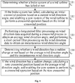
- Fig. 1 is a schematic flow chart of a control method for avoiding a wind turbine run-away according to an embodiment of the present disclosure. As shown in Fig. 1 , the control method for avoiding a wind turbine run-away may include steps 101 to 105.
- step 101 whether a brake system of the wind turbine has failed or not is determined.
- whether the brake system of the wind turbine has failed or not is determined by determining whether the brake system brakes at least two blades to a corresponding predetermined position within a first predetermined time period t1 after receiving a shutdown instruction. It is determined that the brake system has failed, if the brake system fails to brake the at least two blades to the corresponding predetermined position within the first predetermined time period t1 after receiving the shutdown instruction.
- the predetermined position may refer to a variable-pitch brake position
- variable-pitch braking may refer to perform a feathering operation along a plane parallel with a plane of a wind wheel to adjust a position of a blade from a windward surface to a position where an angle between the position and the plane of the wind wheel is 90°, so as to reduce the ability of capturing wind energy.
- whether the brake system of the wind turbine has failed or not may also be determined by determining whether the brake system reduces a rotating speed of the wind turbine to a predetermined rotating speed within a second predetermined time period t2 after receiving the shutdown instruction. It is determined that the brake system has failed, if the brake system fails to reduce the rotating speed of the wind turbine to the predetermined rotating speed within the second predetermined time period t2 after receiving the shutdown instruction.
- step 102 if the brake system has failed, an initial crosswind position is calculated based on a current wind direction angle, and a yaw system of the wind turbine is enabled to perform a crosswind operation based on the initial crosswind position.
- a crosswind position is a relative concept, and is determined based on the wind direction, that is, the crosswind position may change as the wind direction changes.
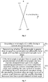
- Fig. 2 is a schematic diagram of a Cartesian coordinate system in which a wind direction is reference 0° according to an embodiment of the present disclosure, wherein the wind direction is represented by B.
- an angle range of [80°, 100°] and [260°, 280°] with respect to the wind direction B is used as the crosswind position range defined by the current wind direction B, even if the angle between the nacelle direction and the wind direction B is within [80, 100] and [260, 280].
- the crosswind position may also be obtained based on a method of simulating a running load of the impeller.
- step 103 a long-period filter processing is performed on wind direction data acquired during a crosswind process to obtain an average wind direction angle, and a short-period filter processing is performed on the wind direction data to obtain an instantaneous wind direction angle.
- the long-period filtering processing is suitable for yawing in a case of a relatively stable wind direction.
- the long-period filter processing is performed on the acquired wind direction data based on a weighting strategy of 30 s.
- the short-period filtering processing is used for a sudden change detection in the wind direction.
- the short-period filter processing is performed on the acquired wind direction data based on a weighting strategy of 5 s.
- Weighting-strategy based filter processing methods may refer to the prior art, and details will not be described herein.
- step 104 whether the wind direction has a sudden change or not is determined based on the average wind direction angle and the instantaneous wind direction angle.
- a difference between the average wind direction angle and the instantaneous wind direction angle is calculated. It is determined that the wind direction has a sudden change if the difference is greater than a preset threshold, and it is determined that the wind direction is relatively stable if the difference is not greater than the preset threshold.
- the average wind direction angle or the instantaneous wind direction angle may also be optimized (for example, by multiplying by some constants or performing some common data processing) based on an actual situation, so that the calculated average wind direction angle and instantaneous wind direction angle is used to accurately determine a sudden change in the wind direction.
- step 105 if the wind direction has a sudden change, a new crosswind position is calculated based on the average wind direction angle, and the yaw system is enabled to perform a crosswind operation based on the new crosswind position.
- a brake system of a wind turbine in order to avoid the occurrence of a run-away failure, whether a brake system of a wind turbine has failed or not is determined first. If the braking system has failed, an initial crosswind position is calculated based on a current wind direction angle, so that a yaw system of the wind turbine may perform a crosswind operation based on the initial crosswind position. Since the captured wind energy can be reduced after performing the crosswind operation, and thus rotating speed of the wind turbine can be reduced, therefore occurrence of a run-away failure can be avoided.
- the crosswind operation can be kept consistent with the wind direction. For example, when the wind direction changes greatly, the crosswind operation of the yaw system can be adjusted in time to improve the wind direction response rate and environmental adaptability of the yaw system.
- the control method for avoiding a wind turbine run-away in the embodiments of the present disclosure can actively determine whether the brake system of the wind turbine has failed, and can automatically enter into a crosswind process based on the determination result. Therefore, compared to triggering the crosswind operation of the yaw system artificially, on one hand, the control method for avoiding a wind turbine run-away has advantages of high timeliness and high accuracy. On the other hand, it can avoid occupational health risks to a maintenance personnel, especially being capable of performing automatic nighttime maintenance in place of a human. As such, it is ensured that a crosswind function is complete on a long-term basis, thereby preventing a crosswind failure caused by factors such as twisted cables, slow changes in the wind direction and sudden changes in the wind direction.
- control method for avoiding a wind turbine run-away in embodiments of the present disclosure does not need to add a new hardware device, and may adopt an implementation manner of a software control strategy, and thus the method has advantages of low cost and being easy to popularize.
- the cable may twist with the yaw system relative to its straight state, for example, one or more turns. Therefore, the yaw system should also meet a risk avoidance requirement for a twisted cable when performing a crosswind operation.
- an unwinding direction of the cable may also be acquired, and the yaw system is enabled to perform the crosswind operation along the unwinding direction to adjust the nacelle direction to the initial crosswind position, to reserve more twistable angles for the cable during a continuous crosswind process.
- the unwinding direction should be counterclockwise, and if the twist direction of the cable is counterclockwise, then the unwinding direction should be clockwise.
- Fig. 3 is a schematic flow chart of a control method for avoiding a wind turbine run-away according to another embodiment of the present disclosure.
- the control method for avoiding a wind turbine run-away may further include steps 301 to 305, for protecting a cable in a case where the yaw system continuously performs a crosswind operation, so as to avoid a wind turbine fault caused by an over-limit of a twist angle of the cable.
- step 301 the twist angle of the cable is acquired during a current crosswind process.
- step 302 whether the twist angle is greater than or equal to a predetermined allowable twist angle and less than a predetermined safe twist angle is determined.
- step 303 if the twist angle is greater than or equal to the predetermined allowable twist angle and less than the predetermined safe twist angle, performance of a next crosswind operation is suspended after the current crosswind process ends, and the yaw system is enabled to resume performing the next crosswind operation along the unwinding direction of the cable when an angle between a current wind direction and the nacelle direction becomes less than a predetermined critical angle.
- Each crosswind position may correspond to one crosswind operation. If the twist angle is greater than or equal to the predetermined allowable twist angle and less than the predetermined safe twist angle, it may indicate that after performing a crosswind operation by the yaw system, the allowable twist angle of the cable has been reached, but the safe twist angle of the cable (i.e., a twisted cable protection value which is set by a safety system of the wind turbine) has not been exceeded.
- the predetermined allowable twist angle and less than the predetermined safe twist angle it may indicate that after performing a crosswind operation by the yaw system, the allowable twist angle of the cable has been reached, but the safe twist angle of the cable (i.e., a twisted cable protection value which is set by a safety system of the wind turbine) has not been exceeded.
- the twist angle of the cable is an absolute concept.
- a position wherein the cable is in a straight state is considered as reference 0°, and the position of the reference 0° is determined by a lifting process of the wind turbine.
- the predetermined allowable twist angle is set to 800°
- the predetermined safe twist angle is set to 900°.
- Those skilled in the art may set a suitable predetermined allowable twist angle and a predetermined safe twist angle based on an actual situation, and there is no limit herein in this aspect.
- an angle between the wind direction and the nacelle direction when the rotating speed of the wind turbine is accelerating is considered as a predetermined critical angle. Since when the angle between the current wind direction and the nacelle direction is less than the predetermined critical angle, the impeller of the wind turbine is in a windward state, and thus the ability of capturing wind energy is strong, which may easily cause the rotating speed of the wind turbine to accelerate. Therefore, the yaw system is enabled to resume performing the next crosswind operation along the current unwinding direction, so as to prevent the wind turbine from causing a run-away failure due to the acceleration of the rotating speed.
- control method for avoiding a wind turbine run-away in embodiments of the present disclosure may further include the following contents.
- the yaw system receives other automatic yaw instructions that are not related to a crosswind operation during the current crosswind process, the other automatic yaw instructions that are not related to the crosswind operation is disabled, and the yaw system is controlled to continue to perform a current crosswind operation.
- the yaw system receives a manual yaw instruction during the current crosswind process, the current crosswind operation is terminated, and the yaw system is controlled to perform the next crosswind operation based on the manual yaw instruction.
- the manual yaw instruction is a manual local yaw instruction or a remote yaw instruction, and the difference between them is in that the sender is different.
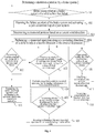
- Fig. 4 is a schematic flow chart of a control method for avoiding a wind turbine run-away according to yet another embodiment of the present disclosure, which is used to illustrate the control method for avoiding a wind turbine run-away in embodiments of the present disclosure in detail by means of an example.
- the control method for avoiding a wind turbine run-away in this example may include steps 401 to 413.
- step 401 whether a brake system of the wind turbine has failed or not is determined. If the brake system of the wind turbine has failed, then the method may proceed to step 402, and if the brake system of the wind turbine has not failed, then the method may return back to step 401.
- step 402 the failure accident of the brake system is alarmed and a yaw crosswind flag of a yaw system is activated.
- the alarm information and the activation information of the yaw crosswind flag is uploaded to a remote monitoring system.
- step 403 a crosswind position is determined based on a current wind direction.
- step 404 a crosswind operation is performed along an unwinding direction of a cable to adjust a nacelle direction to the crosswind position.
- step 405 whether a twist angle of the cable is greater than or equal to a predetermined allowable twist angle and less than a predetermined safe twist angle is determined. If the twist angle of the cable is greater than or equal to the predetermined allowable twist angle and less than the predetermined safe twist angle, then the method may proceed to step 406, otherwise, the method may return back to step 405.
- step 406 performance of a current crosswind operation is continued, and performance of a next crosswind operation is suspended.
- step 407 whether an angle between a wind direction and the nacelle direction is less than a predetermined critical angle is determined. If the angle between the wind direction and the nacelle direction is less than the predetermined critical angle, then the method may proceed to step 408, and if the angle between the wind direction and the nacelle direction is not less than the predetermined critical angle, then the method may return back to step 407.
- step 408 performance of the next crosswind operation is resumed in a current unwinding direction of the cable.
- step 409 whether the wind direction has a sudden change or not during a crosswind process is determined. If the wind direction has a sudden change during the crosswind process, then the method may proceed to step 410, and if the wind direction does not have a sudden change during the crosswind process, then the method may proceed to step 411.
- step 410 a crosswind position is calculated based on an average wind direction angle, and then the method may turn to step 404.
- step 411 a crosswind position is calculated using an instantaneous wind direction angle, and then the method may turn to step 404.
- step 412 whether a manual yaw instruction is received during the crosswind process is determined. If a manual yaw instruction is received during the crosswind process, then the method may proceed to step 413, and if no manual yaw instruction is received during the crosswind process, then the method may return back to step 405.
- step 413 the current crosswind operation is terminated, and a yaw operation is performed based on the manual yaw instruction.
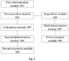
- Fig. 5 is a schematic structural diagram of a control device for avoiding a wind turbine run-away according to an embodiment of the present disclosure.
- the control device for avoiding a wind turbine run-away may include a first determination module 501, a first execution module 502, a calculation module 503, a second determination module 504 and a second execution module 505.
- the first determination module 501 is configured to determine whether a brake system of the wind turbine has failed or not.
- the first execution module 502 is configured to: if the brake system has failed, calculate an initial crosswind position based on a current wind direction angle, and enable a yaw system of the wind turbine to perform a crosswind operation based on the initial crosswind position.
- the first execution module 502 may include an acquisition unit and an execution unit.
- the acquisition unit is configured to obtain an unwinding direction of a cable.
- the execution unit is configured to enable the yaw system to perform the crosswind operation along the unwinding direction to adjust a nacelle direction to the initial crosswind position.
- the calculation module 503 is configured to: perform a long-period filter processing on wind direction data acquired during a crosswind process to obtain an average wind direction angle, and perform a short-period filter processing on the wind direction data to obtain an instantaneous wind direction angle.
- the second determination module 504 is configured to determine whether a wind direction has a sudden change or not based on the average wind direction angle and the instantaneous wind direction angle.
- the second determination module 504 may include a calculation unit and a determination unit.
- the calculation unit is configured to calculate a difference between the average wind direction angle and the instantaneous wind direction angle.
- the determination unit is configured to determine that the wind direction has a sudden change if the difference is greater than a preset threshold.
- the second execution module 505 is configured to: if the wind direction has a sudden change, calculate a new crosswind position based on the average wind direction angle, and enable the yaw system to perform a crosswind operation based on the new crosswind position.
- control device for avoiding a wind turbine run-away may further include an acquisition module 506, a third determination module 507 and a third execution module 508.
- the acquisition module 506 is configured to obtain a twist angle of the cable during a current crosswind process.
- the third determination module 507 is configured to determine whether the twist angle is greater than or equal to a predetermined allowable twist angle and less than a predetermined safe twist angle.
- the third execution module 508 is configured to: if the twist angle is greater than or equal to the predetermined allowable twist angle and less than the predetermined safe twist angle, suspend performance of a next crosswind operation after the current crosswind process ends, and enable the yaw system to resume performing the next crosswind operation along the unwinding direction of the cable when an angle between a current wind direction and the nacelle direction becomes less than a predetermined critical angle.
- control device for avoiding a wind turbine run-away described above is integrated into a main controller of the wind turbine, or is a component capable of performing logic operation independently, and there is no limit herein in this aspect.
- Embodiments of the present disclosure may also provide a wind turbine, which may include the control device for avoiding a wind turbine run-away described above.
- Examples of a machine-readable medium may include an electronic circuit, a semiconductor memory device, a ROM, a flash memory, an erasable ROM (EROM), a floppy disk, a CD-ROM, an optical disk, a hard disk, a fiber optic medium, a radio frequency (RF) link, and the like.
- the code segment is downloaded via a computer network such as the Internet, an intranet, and the like.
Description
- The present disclosure relates to the technology field of wind power generation, and in particular, to a control method and device for avoiding run-away, and a wind turbine.
- In order to protect the safe operation of a wind turbine, when the wind turbine fails, it is necessary to perform an emergency shutdown processing (namely, emergency braking) to the wind turbine using a brake system. At present, brake schemes for the brake system mainly include a pneumatic brake scheme, a mechanical brake scheme or a combination of both. Among them, the pneumatic brake scheme is applied to a wind turbine with a pitch system for blades, wherein a wind power captured by the blades is minimized by independently driving each blade to reach a feathering position. The mechanical brake scheme acts on a transmission mechanism of an impeller, wherein the impeller is forced to brake completely by utilizing a high mechanical friction damping effect of a mechanical brake device (for example, a brake disc).
- However, taking into account uncertainties such as equipment reliability and environmental adaptability, the brake system still has a possibility of overall failure. After the overall failure of the brake system, rotating speed of the wind turbine cannot be effectively controlled, and eventually a run-away failure will occur. A run-away failure can easily cause accidents such as producing fire by friction of a brake disc, causing serious damage to the wind turbine.
-
WO 2010/130057 A2 discloses methods and apparatus for the control of a wind turbine. A system for controlling the RPM of a wind turbine uses inverters to draw current from the wind turbine, thereby slowing the rotational speed of the wind turbine blades.CN 104 314 759 ACN 102 619 688 AJP 2008 309097 A - Embodiments of the present disclosure provide a control method and device for avoiding run-away, and a wind turbine, which can realize a shutdown operation of the wind turbine after the overall failure of a brake system of the wind turbine, thereby avoiding the occurrence of a run-away failure.
- According to a first aspect of embodiments of the present disclosure, there is provided a control method for avoiding a wind turbine run-away including: determining whether a brake system of the wind turbine has failed or not; if the brake system has failed, calculating an initial crosswind position based on a current wind direction angle, and enabling a yaw system of the wind turbine to perform a crosswind operation based on the initial crosswind position; performing a long-period filter processing on wind direction data acquired during a crosswind process to obtain an average wind direction angle, and performing a short-period filter processing on the wind direction data to obtain an instantaneous wind direction angle; determining whether a wind direction has a sudden change or not based on the average wind direction angle and the instantaneous wind direction angle; and if the wind direction has a sudden change, calculating a new crosswind position based on the average wind direction angle, and enabling the yaw system to perform a crosswind operation based on the new crosswind position.
- According to a second aspect of embodiments of the present disclosure, there is provided a control device for avoiding a wind turbine run-away including: a first determination module configured to determine whether a brake system of the wind turbine has failed or not; a first execution module configured to: if the brake system has failed, calculate an initial crosswind position based on a current wind direction angle, and enable a yaw system of the wind turbine to perform a crosswind operation based on the initial crosswind position; a calculation module configured to: perform a long-period filter processing on wind direction data acquired during a crosswind process to obtain an average wind direction angle, and perform a short-period filter processing on the wind direction data to obtain an instantaneous wind direction angle; a second determination module configured to determine whether a wind direction has a sudden change or not based on the average wind direction angle and the instantaneous wind direction angle; and a second execution module configured to: if the wind direction has a sudden change, calculate a new crosswind position based on the average wind direction angle, and enable the yaw system to perform a crosswind operation based on the new crosswind position.
- According to a third aspect of embodiments of the present disclosure, there is provided a wind turbine including the control device for avoiding a wind turbine run-away as described above.
- According to embodiments of the present disclosure, in order to avoid the occurrence of a run-away failure, whether a brake system of a wind turbine has failed or not is determined first. If the braking system has failed, an initial crosswind position is calculated based on a current wind direction angle, so that a yaw system of the wind turbine may perform a crosswind operation on an impeller based on the initial crosswind position. Since the captured wind energy can be reduced after performing the crosswind operation, and thus rotating speed of the wind turbine can be reduced, therefore occurrence of a run-away failure can be avoided.
- In addition, considering the wind direction is constantly changing during a crosswind process, it is also possible to perform a long-period filter processing on wind direction data acquired during the crosswind process to obtain an average wind direction angle, and to perform a short-period filter processing on the wind direction data to obtain an instantaneous wind direction angle. Then whether a wind direction has a sudden change or not is determined based on the average wind direction angle and the instantaneous wind direction angle. If the wind direction has a sudden change, an updated crosswind position is calculated based on the average wind direction angle, and the yaw system is enabled to perform a crosswind operation based on the updated crosswind position. In this way, the crosswind operation can be kept consistent with the wind direction. For example, when the wind direction changes greatly, the crosswind operation of the yaw system can be adjusted in time to improve the wind direction response rate and environmental adaptability of the yaw system.
- In addition, since the control method for avoiding a wind turbine run-away in the embodiments of the present disclosure can actively determine whether the brake system of the wind turbine has failed, and can automatically enter into a crosswind process based on the determination result. Therefore, compared to triggering the crosswind operation of the yaw system artificially, on one hand, the control method for avoiding a wind turbine run-away has advantages of high timeliness and high accuracy. On the other hand, it can avoid occupational health risks to a maintenance personnel, especially being capable of performing automatic nighttime maintenance in place of a human. As such, it is ensured that a crosswind function is complete on a long-term basis, thereby preventing a crosswind failure caused by factors such as twisted cables, slow changes in the wind direction and sudden changes in the wind direction.
-
-
Fig. 1 is a schematic flow chart of a control method for avoiding a wind turbine run-away according to an embodiment of the present disclosure; -
Fig. 2 is a schematic diagram of a Cartesian coordinate system in which a wind direction is reference 0° according to an embodiment of the present disclosure; -
Fig. 3 is a schematic flow chart of a control method for avoiding a wind turbine run-away according to another embodiment of the present disclosure; -
Fig. 4 is a schematic flow chart of a control method for avoiding a wind turbine run-away according to yet another embodiment of the present disclosure; -
Fig. 5 is a schematic structural diagram of a control device for avoiding a wind turbine run-away according to an embodiment of the present disclosure. - Features and exemplary embodiments of various aspects of the present disclosure will be described in detail below. In the following detailed description, numerous specific details are set forth in order to provide a comprehensive understanding of present disclosure.
- Embodiments of the present disclosure provide a control method and device for avoiding run-away, and a wind turbine. By adopting the technical solution in embodiments of the present disclosure, after the overall failure of a brake system of the wind turbine, a shutdown operation of the wind turbine can be realized. That is, this technical solution can be used as a further defense after the brake system fails, thereby avoiding the occurrence of a run-away failure.
- In general, a yaw system is provided in a wind turbine. Depending on an implementation purpose, the yaw system may perform a windward operation and a crosswind operation.
- When the yaw system performs the windward operation, a rotation plane of an impeller is adjusted to be perpendicular to a wind direction, so that the impeller may capture maximized wind energy.
- When the yaw system performs the crosswind operation, the rotation plane of the impeller is adjusted to be parallel with the wind direction, that is, an angle between a nacelle direction and the wind direction is adjusted to nearly 90°, so that the wind energy that the impeller can capture is reduced, thereby reducing a rotating speed of the wind turbine. When the rotation plane of the impeller is completely parallel with the wind direction, the rotating speed of the wind turbine is reduced to 0, so as to achieve the purpose of shutting down the wind turbine.
- With this principle, after the overall failure of the brake system of the wind turbine, the rotation plane of the impeller is adjusted to be completely parallel with the wind direction by triggering a crosswind function of the yaw system, so as to achieve the purpose of reducing the rotating speed of the wind turbine and avoiding a run-away failure.
-
Fig. 1 is a schematic flow chart of a control method for avoiding a wind turbine run-away according to an embodiment of the present disclosure. As shown inFig. 1 , the control method for avoiding a wind turbine run-away may includesteps 101 to 105. - In
step 101, whether a brake system of the wind turbine has failed or not is determined. - In an alternative embodiment, whether the brake system of the wind turbine has failed or not is determined by determining whether the brake system brakes at least two blades to a corresponding predetermined position within a first predetermined time period t1 after receiving a shutdown instruction. It is determined that the brake system has failed, if the brake system fails to brake the at least two blades to the corresponding predetermined position within the first predetermined time period t1 after receiving the shutdown instruction.
- The predetermined position may refer to a variable-pitch brake position, and variable-pitch braking may refer to perform a feathering operation along a plane parallel with a plane of a wind wheel to adjust a position of a blade from a windward surface to a position where an angle between the position and the plane of the wind wheel is 90°, so as to reduce the ability of capturing wind energy.
- In an alternative embodiment, whether the brake system of the wind turbine has failed or not may also be determined by determining whether the brake system reduces a rotating speed of the wind turbine to a predetermined rotating speed within a second predetermined time period t2 after receiving the shutdown instruction. It is determined that the brake system has failed, if the brake system fails to reduce the rotating speed of the wind turbine to the predetermined rotating speed within the second predetermined time period t2 after receiving the shutdown instruction.
- It should be noted that, since a position after braking and a rotating speed after braking are two independent indicators, the above methods of determining whether the brake system has failed or not based on a predetermined position and a predetermined rotating speed is performed separately. It is determined that the brake system has failed as long as any one of the conditions is met.
- In
step 102, if the brake system has failed, an initial crosswind position is calculated based on a current wind direction angle, and a yaw system of the wind turbine is enabled to perform a crosswind operation based on the initial crosswind position. - A crosswind position is a relative concept, and is determined based on the wind direction, that is, the crosswind position may change as the wind direction changes.
-
Fig. 2 is a schematic diagram of a Cartesian coordinate system in which a wind direction is reference 0° according to an embodiment of the present disclosure, wherein the wind direction is represented by B. - In an alternative embodiment, an angle range of [80°, 100°] and [260°, 280°] with respect to the wind direction B is used as the crosswind position range defined by the current wind direction B, even if the angle between the nacelle direction and the wind direction B is within [80, 100] and [260, 280].
- In an alternative embodiment, the crosswind position may also be obtained based on a method of simulating a running load of the impeller.
- In
step 103, a long-period filter processing is performed on wind direction data acquired during a crosswind process to obtain an average wind direction angle, and a short-period filter processing is performed on the wind direction data to obtain an instantaneous wind direction angle. - The long-period filtering processing is suitable for yawing in a case of a relatively stable wind direction. For example, the long-period filter processing is performed on the acquired wind direction data based on a weighting strategy of 30 s.
- The short-period filtering processing is used for a sudden change detection in the wind direction. For example, the short-period filter processing is performed on the acquired wind direction data based on a weighting strategy of 5 s. Weighting-strategy based filter processing methods may refer to the prior art, and details will not be described herein.
- In
step 104, whether the wind direction has a sudden change or not is determined based on the average wind direction angle and the instantaneous wind direction angle. - In an alternative embodiment, a difference between the average wind direction angle and the instantaneous wind direction angle is calculated. It is determined that the wind direction has a sudden change if the difference is greater than a preset threshold, and it is determined that the wind direction is relatively stable if the difference is not greater than the preset threshold.
- In an alternative embodiment, the average wind direction angle or the instantaneous wind direction angle may also be optimized (for example, by multiplying by some constants or performing some common data processing) based on an actual situation, so that the calculated average wind direction angle and instantaneous wind direction angle is used to accurately determine a sudden change in the wind direction.
- In
step 105, if the wind direction has a sudden change, a new crosswind position is calculated based on the average wind direction angle, and the yaw system is enabled to perform a crosswind operation based on the new crosswind position. - According to an embodiment of the present disclosure, in order to avoid the occurrence of a run-away failure, whether a brake system of a wind turbine has failed or not is determined first. If the braking system has failed, an initial crosswind position is calculated based on a current wind direction angle, so that a yaw system of the wind turbine may perform a crosswind operation based on the initial crosswind position. Since the captured wind energy can be reduced after performing the crosswind operation, and thus rotating speed of the wind turbine can be reduced, therefore occurrence of a run-away failure can be avoided.
- In addition, considering the wind direction is constantly changing during a crosswind process, it is also possible to perform a long-period filter processing on wind direction data acquired during the crosswind process to obtain an average wind direction angle, and to perform a short-period filter processing on the wind direction data to obtain an instantaneous wind direction angle. Then whether a wind direction has a sudden change or not is determined based on the average wind direction angle and the instantaneous wind direction angle. If the wind direction has a sudden change, an updated crosswind position is calculated based on the average wind direction angle, and the yaw system is enabled to perform a crosswind operation based on the updated crosswind position. In this way, the crosswind operation can be kept consistent with the wind direction. For example, when the wind direction changes greatly, the crosswind operation of the yaw system can be adjusted in time to improve the wind direction response rate and environmental adaptability of the yaw system.
- In addition, since the control method for avoiding a wind turbine run-away in the embodiments of the present disclosure can actively determine whether the brake system of the wind turbine has failed, and can automatically enter into a crosswind process based on the determination result. Therefore, compared to triggering the crosswind operation of the yaw system artificially, on one hand, the control method for avoiding a wind turbine run-away has advantages of high timeliness and high accuracy. On the other hand, it can avoid occupational health risks to a maintenance personnel, especially being capable of performing automatic nighttime maintenance in place of a human. As such, it is ensured that a crosswind function is complete on a long-term basis, thereby preventing a crosswind failure caused by factors such as twisted cables, slow changes in the wind direction and sudden changes in the wind direction.
- In addition, since the control method for avoiding a wind turbine run-away in embodiments of the present disclosure does not need to add a new hardware device, and may adopt an implementation manner of a software control strategy, and thus the method has advantages of low cost and being easy to popularize.
- Further, considering that a cable connecting a nacelle and a bottom of a tower is disposed in a nacelle cabinet of the wind turbine, the cable may twist with the yaw system relative to its straight state, for example, one or more turns. Therefore, the yaw system should also meet a risk avoidance requirement for a twisted cable when performing a crosswind operation.
- In an alternative embodiment, when performing a crosswind operation of the yaw system, an unwinding direction of the cable may also be acquired, and the yaw system is enabled to perform the crosswind operation along the unwinding direction to adjust the nacelle direction to the initial crosswind position, to reserve more twistable angles for the cable during a continuous crosswind process.
- As an example, if a twist direction of the cable is clockwise, then the unwinding direction should be counterclockwise, and if the twist direction of the cable is counterclockwise, then the unwinding direction should be clockwise.
-
Fig. 3 is a schematic flow chart of a control method for avoiding a wind turbine run-away according to another embodiment of the present disclosure. As shown inFig. 3 , the control method for avoiding a wind turbine run-away may further includesteps 301 to 305, for protecting a cable in a case where the yaw system continuously performs a crosswind operation, so as to avoid a wind turbine fault caused by an over-limit of a twist angle of the cable. - In
step 301, the twist angle of the cable is acquired during a current crosswind process. - In
step 302, whether the twist angle is greater than or equal to a predetermined allowable twist angle and less than a predetermined safe twist angle is determined. - In
step 303, if the twist angle is greater than or equal to the predetermined allowable twist angle and less than the predetermined safe twist angle, performance of a next crosswind operation is suspended after the current crosswind process ends, and the yaw system is enabled to resume performing the next crosswind operation along the unwinding direction of the cable when an angle between a current wind direction and the nacelle direction becomes less than a predetermined critical angle. - Each crosswind position may correspond to one crosswind operation. If the twist angle is greater than or equal to the predetermined allowable twist angle and less than the predetermined safe twist angle, it may indicate that after performing a crosswind operation by the yaw system, the allowable twist angle of the cable has been reached, but the safe twist angle of the cable (i.e., a twisted cable protection value which is set by a safety system of the wind turbine) has not been exceeded.
- Herein, the twist angle of the cable is an absolute concept. A position wherein the cable is in a straight state is considered as reference 0°, and the position of the reference 0° is determined by a lifting process of the wind turbine. In one example, the predetermined allowable twist angle is set to 800°, and the predetermined safe twist angle is set to 900°. Those skilled in the art may set a suitable predetermined allowable twist angle and a predetermined safe twist angle based on an actual situation, and there is no limit herein in this aspect.
- In an alternative embodiment, an angle between the wind direction and the nacelle direction when the rotating speed of the wind turbine is accelerating is considered as a predetermined critical angle. Since when the angle between the current wind direction and the nacelle direction is less than the predetermined critical angle, the impeller of the wind turbine is in a windward state, and thus the ability of capturing wind energy is strong, which may easily cause the rotating speed of the wind turbine to accelerate. Therefore, the yaw system is enabled to resume performing the next crosswind operation along the current unwinding direction, so as to prevent the wind turbine from causing a run-away failure due to the acceleration of the rotating speed. In the following, considering that the yaw system may continuously receive other yaw instructions during performance of a crosswind operation, in order to avoid a conflict of instruction execution and successfully prevent a run-away failure, the control method for avoiding a wind turbine run-away in embodiments of the present disclosure may further include the following contents.
- In an alternative embodiment, if the yaw system receives other automatic yaw instructions that are not related to a crosswind operation during the current crosswind process, the other automatic yaw instructions that are not related to the crosswind operation is disabled, and the yaw system is controlled to continue to perform a current crosswind operation.
- Other yaw instructions that are not related to a crosswind operation may include: a windward yaw instruction, an unwinding yaw instruction and a lubrication yaw instruction, which are common operation instructions in the field of wind power generation.
- In an alternative embodiment, if the yaw system receives a manual yaw instruction during the current crosswind process, the current crosswind operation is terminated, and the yaw system is controlled to perform the next crosswind operation based on the manual yaw instruction.
- Herein, the manual yaw instruction is a manual local yaw instruction or a remote yaw instruction, and the difference between them is in that the sender is different.
-
Fig. 4 is a schematic flow chart of a control method for avoiding a wind turbine run-away according to yet another embodiment of the present disclosure, which is used to illustrate the control method for avoiding a wind turbine run-away in embodiments of the present disclosure in detail by means of an example. As shown inFig. 4 , the control method for avoiding a wind turbine run-away in this example may includesteps 401 to 413. - In
step 401, whether a brake system of the wind turbine has failed or not is determined. If the brake system of the wind turbine has failed, then the method may proceed to step 402, and if the brake system of the wind turbine has not failed, then the method may return back tostep 401. - In
step 402, the failure accident of the brake system is alarmed and a yaw crosswind flag of a yaw system is activated. The alarm information and the activation information of the yaw crosswind flag is uploaded to a remote monitoring system. - In
step 403, a crosswind position is determined based on a current wind direction. - In
step 404, a crosswind operation is performed along an unwinding direction of a cable to adjust a nacelle direction to the crosswind position. - In
step 405, whether a twist angle of the cable is greater than or equal to a predetermined allowable twist angle and less than a predetermined safe twist angle is determined. If the twist angle of the cable is greater than or equal to the predetermined allowable twist angle and less than the predetermined safe twist angle, then the method may proceed to step 406, otherwise, the method may return back tostep 405. - In
step 406, performance of a current crosswind operation is continued, and performance of a next crosswind operation is suspended. - In
step 407, whether an angle between a wind direction and the nacelle direction is less than a predetermined critical angle is determined. If the angle between the wind direction and the nacelle direction is less than the predetermined critical angle, then the method may proceed to step 408, and if the angle between the wind direction and the nacelle direction is not less than the predetermined critical angle, then the method may return back tostep 407. - In
step 408, performance of the next crosswind operation is resumed in a current unwinding direction of the cable. - In
step 409, whether the wind direction has a sudden change or not during a crosswind process is determined. If the wind direction has a sudden change during the crosswind process, then the method may proceed to step 410, and if the wind direction does not have a sudden change during the crosswind process, then the method may proceed to step 411. - In
step 410, a crosswind position is calculated based on an average wind direction angle, and then the method may turn to step 404. - In
step 411, a crosswind position is calculated using an instantaneous wind direction angle, and then the method may turn to step 404. - In
step 412, whether a manual yaw instruction is received during the crosswind process is determined. If a manual yaw instruction is received during the crosswind process, then the method may proceed to step 413, and if no manual yaw instruction is received during the crosswind process, then the method may return back tostep 405. - In
step 413, the current crosswind operation is terminated, and a yaw operation is performed based on the manual yaw instruction. -
Fig. 5 is a schematic structural diagram of a control device for avoiding a wind turbine run-away according to an embodiment of the present disclosure. As shown inFig. 5 , the control device for avoiding a wind turbine run-away may include a first determination module 501, afirst execution module 502, acalculation module 503, a second determination module 504 and asecond execution module 505. - The first determination module 501 is configured to determine whether a brake system of the wind turbine has failed or not.
- The
first execution module 502 is configured to: if the brake system has failed, calculate an initial crosswind position based on a current wind direction angle, and enable a yaw system of the wind turbine to perform a crosswind operation based on the initial crosswind position. - In an alternative embodiment, the
first execution module 502 may include an acquisition unit and an execution unit. The acquisition unit is configured to obtain an unwinding direction of a cable. The execution unit is configured to enable the yaw system to perform the crosswind operation along the unwinding direction to adjust a nacelle direction to the initial crosswind position. - The
calculation module 503 is configured to: perform a long-period filter processing on wind direction data acquired during a crosswind process to obtain an average wind direction angle, and perform a short-period filter processing on the wind direction data to obtain an instantaneous wind direction angle. - The second determination module 504 is configured to determine whether a wind direction has a sudden change or not based on the average wind direction angle and the instantaneous wind direction angle.
- In an alternative embodiment, the second determination module 504 may include a calculation unit and a determination unit. The calculation unit is configured to calculate a difference between the average wind direction angle and the instantaneous wind direction angle. The determination unit is configured to determine that the wind direction has a sudden change if the difference is greater than a preset threshold.
- The
second execution module 505 is configured to: if the wind direction has a sudden change, calculate a new crosswind position based on the average wind direction angle, and enable the yaw system to perform a crosswind operation based on the new crosswind position. - In an alternative embodiment, as shown in
Fig. 5 , the control device for avoiding a wind turbine run-away may further include anacquisition module 506, athird determination module 507 and athird execution module 508. - The
acquisition module 506 is configured to obtain a twist angle of the cable during a current crosswind process. - The
third determination module 507 is configured to determine whether the twist angle is greater than or equal to a predetermined allowable twist angle and less than a predetermined safe twist angle. - The
third execution module 508 is configured to: if the twist angle is greater than or equal to the predetermined allowable twist angle and less than the predetermined safe twist angle, suspend performance of a next crosswind operation after the current crosswind process ends, and enable the yaw system to resume performing the next crosswind operation along the unwinding direction of the cable when an angle between a current wind direction and the nacelle direction becomes less than a predetermined critical angle. - It should be noted that, the control device for avoiding a wind turbine run-away described above is integrated into a main controller of the wind turbine, or is a component capable of performing logic operation independently, and there is no limit herein in this aspect.
- Embodiments of the present disclosure may also provide a wind turbine, which may include the control device for avoiding a wind turbine run-away described above.
- It should also be noted that, functional blocks shown in structure diagrams described above is implemented as hardware, software, firmware, or a combination thereof. When implemented in hardware, it can be, for example, an electronic circuit, an application specific integrated circuit (ASIC), suitable firmware, a plug-in, a function card, and the like. When implemented in software, elements in embodiments of the present disclosure is a program or a code segment that can be used to perform a required task. The program or code segment is stored in a machine-readable medium, or is transmitted over a transmission medium or communication link through a data signal carried in a carrier. A "machine-readable medium" may include any medium capable of storing or transferring information. Examples of a machine-readable medium may include an electronic circuit, a semiconductor memory device, a ROM, a flash memory, an erasable ROM (EROM), a floppy disk, a CD-ROM, an optical disk, a hard disk, a fiber optic medium, a radio frequency (RF) link, and the like. The code segment is downloaded via a computer network such as the Internet, an intranet, and the like.
- The scope of protection is defined by the appended claims.
Claims (12)
- A control method for avoiding a wind turbine run-away, comprising:determining whether a brake system of the wind turbine has failed or not;if the brake system has failed, calculating an initial crosswind position based on a current wind direction angle, and enabling a yaw system of the wind turbine to perform a crosswind operation based on the initial crosswind position;performing a long-period filter processing on wind direction data acquired during a crosswind process to obtain an average wind direction angle, and performing a short-period filter processing on the wind direction data to obtain an instantaneous wind direction angle;determining whether a wind direction has a sudden change or not based on the average wind direction angle and the instantaneous wind direction angle; andif the wind direction has a sudden change, calculating a new crosswind position based on the average wind direction angle, and enabling the yaw system to perform a crosswind operation based on the new crosswind position.
- The method of claim 1, wherein the determining whether the wind direction has a sudden change based on the average wind direction angle and the instantaneous wind direction angle comprises:calculating a difference between the average wind direction angle and the instantaneous wind direction angle; anddetermining that the wind direction has a sudden change if the difference is greater than a preset threshold.
- The method of claim 1, wherein a cable is disposed in a nacelle cabinet of the wind turbine, and the enabling the yaw system of the wind turbine to perform a crosswind operation based on the initial crosswind position comprises:acquiring an unwinding direction of the cable; andenabling the yaw system to perform the crosswind operation along the unwinding direction to adjust a nacelle direction to the initial crosswind position .
- The method of claim 3, wherein the method further comprises:acquiring a twist angle of the cable during a current crosswind process;determining whether the twist angle is greater than or equal to a predetermined allowable twist angle and less than a predetermined safe twist angle;if the twist angle is greater than or equal to the predetermined allowable twist angle and less than the predetermined safe twist angle, suspending performance of a next crosswind operation after the current crosswind process ends, and enabling the yaw system to resume performing the next crosswind operation along the unwinding direction of the cable when an angle between a current wind direction and the nacelle direction becomes less than a predetermined critical angle.
- The method of claim 1, wherein the determining whether the brake system of the wind turbine has failed or not comprises:determining whether the brake system brakes at least two blades to a corresponding predetermined position within a first predetermined time period after receiving a shutdown instruction, anddetermining that the brake system has failed, if the brake system fails to brake the at least two blades to the corresponding predetermined position within the first predetermined time period after receiving the shutdown instruction; ordetermining whether the brake system reduces a rotating speed of the wind turbine to a predetermined rotating speed within a second predetermined time period after receiving the shutdown instruction, anddetermining that the brake system has failed, if the brake system fails to reduce the rotating speed of the wind turbine to the predetermined rotating speed within the second predetermined time period after receiving the shutdown instruction.
- The method of claim 1, wherein the method further comprises:if the yaw system receives other automatic yaw instructions that are not related to a crosswind operation during a current crosswind process, disabling the other automatic yaw instructions that are not related to the crosswind operation, and controlling the yaw system to continue to perform a current crosswind operation;if the yaw system receives a manual yaw instruction during the current crosswind process, terminating the current crosswind operation, and controlling the yaw system to perform a next crosswind operation based on the manual yaw instruction.
- A control device for avoiding a wind turbine run-away, comprising:a first determination module configured to determine whether a brake system of the wind turbine has failed or not;a first execution module configured to: if the brake system has failed, calculate an initial crosswind position based on a current wind direction angle, and enable a yaw system of the wind turbine to perform a crosswind operation based on the initial crosswind position;a calculation module configured to: perform a long-period filter processing on wind direction data acquired during a crosswind process to obtain an average wind direction angle, and perform a short-period filter processing on the wind direction data to obtain an instantaneous wind direction angle;a second determination module configured to determine whether a wind direction has a sudden change or not based on the average wind direction angle and the instantaneous wind direction angle; anda second execution module configured to: if the wind direction has a sudden change, calculate a new crosswind position based on the average wind direction angle, and enable the yaw system to perform a crosswind operation based on the new crosswind position.
- The device of claim 7, wherein the second determination module comprises:a calculation unit configured to calculate a difference between the average wind direction angle and the instantaneous wind direction angle;a determination unit configured to determine that the wind direction has a sudden change if the difference is greater than a preset threshold.
- The device of claim 7, wherein a cable is disposed in a nacelle cabinet of the wind turbine, and the first execution module comprises:an acquisition unit configured to acquire an unwinding direction of the cable;an execution unit configured to enable the yaw system to perform the crosswind operation along the unwinding direction to adjust a nacelle direction to the initial crosswind position.
- The device of claim 9, wherein the device further comprises:an acquisition module configured to acquire a twist angle of the cable during a current crosswind process;a third determination module configured to determine whether the twist angle is greater than or equal to a predetermined allowable twist angle and less than a predetermined safe twist angle;a third execution module configured to: if the twist angle is greater than or equal to the predetermined allowable twist angle and less than the predetermined safe twist angle, suspend performance of a next crosswind operation after the current crosswind process ends, and enable the yaw system to resume performing the next crosswind operation along the unwinding direction of the cable when an angle between a current wind direction and the nacelle direction becomes less than a predetermined critical angle.
- The device of claim 10, wherein the device is integrated into a main controller of the wind turbine.
- A wind turbine comprising the control device for avoiding a wind turbine run-away according to any one of claims 7-11.
Applications Claiming Priority (2)
| Application Number | Priority Date | Filing Date | Title |
|---|---|---|---|
| CN201810171876.0A CN108488037B (en) | 2018-03-01 | 2018-03-01 | Anti-runaway control method and device and wind generating set |
| PCT/CN2018/095302 WO2019165744A1 (en) | 2018-03-01 | 2018-07-11 | Overspeed preventing control method and apparatus, and wind turbine |
Publications (4)
| Publication Number | Publication Date |
|---|---|
| EP3557047A1 EP3557047A1 (en) | 2019-10-23 |
| EP3557047A4 EP3557047A4 (en) | 2020-12-16 |
| EP3557047B1 true EP3557047B1 (en) | 2021-09-29 |
| EP3557047B8 EP3557047B8 (en) | 2021-12-15 |
Family
ID=63341142
Family Applications (1)
| Application Number | Title | Priority Date | Filing Date |
|---|---|---|---|
| EP18887198.2A Active EP3557047B8 (en) | 2018-03-01 | 2018-07-11 | Control method and device for avoiding run-away and wind turbine |
Country Status (6)
| Country | Link |
|---|---|
| US (1) | US11365716B2 (en) |
| EP (1) | EP3557047B8 (en) |
| CN (1) | CN108488037B (en) |
| AU (1) | AU2018386361B2 (en) |
| ES (1) | ES2899573T3 (en) |
| WO (1) | WO2019165744A1 (en) |
Families Citing this family (5)
| Publication number | Priority date | Publication date | Assignee | Title |
|---|---|---|---|---|
| CN110374800B (en) * | 2019-06-06 | 2021-01-05 | 北京优利康达科技股份有限公司 | Device for preventing fan from catching fire and galloping and control method |
| CN112576453B (en) * | 2020-11-12 | 2021-11-19 | 南京力思拓能源科技有限公司 | Wind driven generator anemorumbometer state evaluation method and system based on Doppler laser radar technology |
| CN112594131B (en) * | 2020-11-26 | 2022-04-26 | 中国船舶重工集团海装风电股份有限公司 | Method and system for controlling yaw of wind generating set during crosswind and related components |
| CN114704438B (en) * | 2022-06-02 | 2022-09-20 | 深圳众城卓越科技有限公司 | Wind turbine generator set fault monitoring method and device |
| CN115614220A (en) * | 2022-09-08 | 2023-01-17 | 华能新能源股份有限公司河北分公司 | Wind generating set side wind yaw control system and method and generating set |
Family Cites Families (33)
| Publication number | Priority date | Publication date | Assignee | Title |
|---|---|---|---|---|
| US5278773A (en) * | 1990-09-10 | 1994-01-11 | Zond Systems Inc. | Control systems for controlling a wind turbine |
| NZ511059A (en) * | 1998-11-26 | 2003-08-29 | Aloys Wobben | Azimuthal driving system for wind turbines having a three-phase asynchronous motor that uses alternating current during adjusment of the wind turbine and direct current during the standstill period |
| DE10106208C2 (en) * | 2001-02-10 | 2002-12-19 | Aloys Wobben | Wind turbine |
| CA2522280A1 (en) * | 2003-04-17 | 2004-10-28 | New World Generation Inc. | Wind turbine with friction drive power take off on outer rim |
| US20060153672A1 (en) | 2003-04-24 | 2006-07-13 | Davis Dean A | Furling wind turbine |
| DE102006001613B4 (en) * | 2006-01-11 | 2008-01-31 | Repower Systems Ag | Method for operating a wind turbine and wind turbine |
| JP4939286B2 (en) * | 2007-04-10 | 2012-05-23 | 三菱重工業株式会社 | Wind power generator and control method thereof |
| JP2008309097A (en) | 2007-06-15 | 2008-12-25 | Ebara Corp | Wind power generation equipment and method of controlling windmill for wind power generation |
| DE102007045437A1 (en) | 2007-09-22 | 2009-04-02 | Nordex Energy Gmbh | Method for controlling a wind energy plant |
| JP5199828B2 (en) * | 2008-10-29 | 2013-05-15 | 三菱重工業株式会社 | Wind power generator and control method thereof |
| US7786608B2 (en) | 2008-11-17 | 2010-08-31 | General Electric Company | Protection system for wind turbine |
| JP5566609B2 (en) * | 2009-01-05 | 2014-08-06 | 三菱重工業株式会社 | Wind power generator and control method for wind power generator |
| US20100209246A1 (en) * | 2009-02-13 | 2010-08-19 | Robert Migliori | Yaw controller for downwind wind turbines |
| AU2010246876A1 (en) * | 2009-05-15 | 2012-01-19 | Redriven Power Inc. | System and method for controlling a wind turbine |
| JP2011127551A (en) * | 2009-12-18 | 2011-06-30 | Mitsubishi Heavy Ind Ltd | Wind-powered generator apparatus |
| US9062653B2 (en) * | 2010-08-23 | 2015-06-23 | Vestas Wind Systems A/S | Changing a mode of operation of a wind turbine |
| GB2487715A (en) * | 2011-01-18 | 2012-08-08 | Vestas Wind Sys As | Method and apparatus for protecting wind turbines from extreme wind direction changes |
| CN102619688A (en) | 2012-04-18 | 2012-08-01 | 中船重工(重庆)海装风电设备有限公司 | Wind turbine generator system brake control device and wind turbine generator system brake control method |
| KR101346275B1 (en) | 2012-09-04 | 2014-01-03 | 삼성중공업 주식회사 | Method for driving yaw of wind power generator without cable twist |
| CN102828909B (en) * | 2012-09-12 | 2014-04-02 | 国电联合动力技术有限公司 | Method, device and system for safety protection used in failure of putting away oar of blade of wind turbine generator |
| DE102012221289A1 (en) * | 2012-11-21 | 2014-05-22 | Repower Systems Se | Method for operating a wind turbine and wind turbine |
| CN103225586B (en) | 2013-04-26 | 2015-02-25 | 北京天诚同创电气有限公司 | Anti-runaway safety control method for wind generating set |
| EP2860392B1 (en) | 2013-10-09 | 2018-03-07 | Siemens Aktiengesellschaft | Method for adjusting the yaw angle of a wind turbine relative to a given wind direction |
| CN104179636B (en) | 2014-07-25 | 2017-02-15 | 北车风电有限公司 | Method for preventing wind generating set from runaway |
| CN104314759A (en) | 2014-10-23 | 2015-01-28 | 内蒙古久和能源科技有限公司 | Wind direction weighted filtering-based automatic yaw controlling method for wind generating set |
| JP6628983B2 (en) | 2015-06-02 | 2020-01-15 | ナブテスコ株式会社 | Windmill drive unit and windmill drive unit |
| CN107514337B (en) | 2016-06-17 | 2019-08-09 | 北京天诚同创电气有限公司 | Control method and device of wind generating set and wind power plant group control system |
| CN205977543U (en) * | 2016-06-29 | 2017-02-22 | 国电联合动力技术有限公司 | Wind turbine generator system prevent exceeding speed limit controlling means , driftage system and wind turbine generator system |
| CN107620670A (en) * | 2016-07-13 | 2018-01-23 | 北京国电思达科技有限公司 | A kind of anti-hypervelocity Yaw control method of Wind turbines |
| ES2875430T3 (en) * | 2016-10-07 | 2021-11-10 | Siemens Gamesa Renewable Energy As | Determination of the inclination angle of a wind turbine tower |
| CN107701372B (en) * | 2017-10-18 | 2019-06-11 | 明阳智慧能源集团股份公司 | A kind of wind power generating set self-protection control method under variable pitch Actuators Failures |
| CN110094296B (en) * | 2018-01-29 | 2020-06-09 | 江苏金风科技有限公司 | Yaw control method and device of wind generating set under typhoon |
| US10364799B1 (en) * | 2018-02-09 | 2019-07-30 | Inventus Holdings, Llc | Secure windfarm power production during a SCADA system offline mode |
-
2018
- 2018-03-01 CN CN201810171876.0A patent/CN108488037B/en active Active
- 2018-07-11 EP EP18887198.2A patent/EP3557047B8/en active Active
- 2018-07-11 WO PCT/CN2018/095302 patent/WO2019165744A1/en unknown
- 2018-07-11 AU AU2018386361A patent/AU2018386361B2/en active Active
- 2018-07-11 ES ES18887198T patent/ES2899573T3/en active Active
- 2018-07-11 US US16/471,652 patent/US11365716B2/en active Active
Also Published As
| Publication number | Publication date |
|---|---|
| EP3557047A4 (en) | 2020-12-16 |
| US20210246873A1 (en) | 2021-08-12 |
| US11365716B2 (en) | 2022-06-21 |
| WO2019165744A1 (en) | 2019-09-06 |
| EP3557047A1 (en) | 2019-10-23 |
| AU2018386361A1 (en) | 2019-09-19 |
| EP3557047B8 (en) | 2021-12-15 |
| ES2899573T3 (en) | 2022-03-14 |
| CN108488037B (en) | 2019-07-19 |
| CN108488037A (en) | 2018-09-04 |
| AU2018386361B2 (en) | 2021-02-25 |
Similar Documents
| Publication | Publication Date | Title |
|---|---|---|
| EP3557047B1 (en) | Control method and device for avoiding run-away and wind turbine | |
| JP5117677B2 (en) | Wind farm and its control method | |
| EP2486272B1 (en) | Control method for a wind turbine | |
| US8829699B2 (en) | Rotational speed control of a wind turbine based on rotor acceleration | |
| CN102828909B (en) | Method, device and system for safety protection used in failure of putting away oar of blade of wind turbine generator | |
| CA2787441C (en) | Wind energy plant having a blade heater | |
| EP3597910B1 (en) | System and method for reducing loads during an idling or parked state of a wind turbine with a stuck rotor blade | |
| EP3597904B1 (en) | System and method for reducing wind turbine loads by yawing the nacelle to a predetermined position based on rotor imbalance | |
| CN105240214A (en) | Safety circuit for overspeed protection of wind turbine generating set | |
| CN110700997A (en) | Method for monitoring rotating speed of impeller of wind power pitch control system | |
| CN111425350B (en) | Control method and device for pitch system of wind turbine generator and pitch system | |
| CN112128053B (en) | Blade feathering control method, wind generating set main controller and variable pitch controller | |
| CN114718811A (en) | Self-adaptive control method for monitoring fan blade state based on GPS | |
| CN112145344B (en) | Cable-releasing control method and device for wind generating set | |
| CN111219294B (en) | Active yaw mitigation of wind-induced vibration | |
| CN209800161U (en) | Become oar system with initiative safe feathering function | |
| CN214660615U (en) | Wind turbine generator system overspeed protection system | |
| EP4310322A1 (en) | A method and a system for controlling a floating wind turbine | |
| EP2851559B1 (en) | Method and arrangement for controlling a rotor movement of a wind turbine rotor | |
| CN117267048A (en) | Intelligent emergency yaw protection method for wind turbine generator | |
| CN117514612A (en) | Method and device for restraining flutter of wind driven generator, control system and wind driven generator | |
| KR20230155964A (en) | Wind turbine control | |
| CN118030378A (en) | Wind driven generator blade vibration suppression method and related equipment | |
| JP3184277U (en) | Power generation system | |
| CN115559853A (en) | Method, system, medium and equipment for eliminating vortex-induced vibration of fan blade |
Legal Events
| Date | Code | Title | Description |
|---|---|---|---|
| STAA | Information on the status of an ep patent application or granted ep patent |
Free format text: STATUS: UNKNOWN |
|
| STAA | Information on the status of an ep patent application or granted ep patent |
Free format text: STATUS: THE INTERNATIONAL PUBLICATION HAS BEEN MADE |
|
| PUAI | Public reference made under article 153(3) epc to a published international application that has entered the european phase |
Free format text: ORIGINAL CODE: 0009012 |
|
| STAA | Information on the status of an ep patent application or granted ep patent |
Free format text: STATUS: REQUEST FOR EXAMINATION WAS MADE |
|
| 17P | Request for examination filed |
Effective date: 20190617 |
|
| AK | Designated contracting states |
Kind code of ref document: A1 Designated state(s): AL AT BE BG CH CY CZ DE DK EE ES FI FR GB GR HR HU IE IS IT LI LT LU LV MC MK MT NL NO PL PT RO RS SE SI SK SM TR |
|
| STAA | Information on the status of an ep patent application or granted ep patent |
Free format text: STATUS: REQUEST FOR EXAMINATION WAS MADE |
|
| R17P | Request for examination filed (corrected) |
Effective date: 20190617 |
|
| A4 | Supplementary search report drawn up and despatched |
Effective date: 20201113 |
|
| RIC1 | Information provided on ipc code assigned before grant |
Ipc: F03D 7/04 20060101AFI20201109BHEP Ipc: F03D 7/02 20060101ALI20201109BHEP |
|
| GRAP | Despatch of communication of intention to grant a patent |
Free format text: ORIGINAL CODE: EPIDOSNIGR1 |
|
| STAA | Information on the status of an ep patent application or granted ep patent |
Free format text: STATUS: GRANT OF PATENT IS INTENDED |
|
| RIC1 | Information provided on ipc code assigned before grant |
Ipc: F03D 7/02 20060101ALI20210528BHEP Ipc: F03D 7/04 20060101AFI20210528BHEP |
|
| INTG | Intention to grant announced |
Effective date: 20210618 |
|
| GRAS | Grant fee paid |
Free format text: ORIGINAL CODE: EPIDOSNIGR3 |
|
| GRAA | (expected) grant |
Free format text: ORIGINAL CODE: 0009210 |
|
| STAA | Information on the status of an ep patent application or granted ep patent |
Free format text: STATUS: THE PATENT HAS BEEN GRANTED |
|
| AK | Designated contracting states |
Kind code of ref document: B1 Designated state(s): AL AT BE BG CH CY CZ DE DK EE ES FI FR GB GR HR HU IE IS IT LI LT LU LV MC MK MT NL NO PL PT RO RS SE SI SK SM TR |
|
| REG | Reference to a national code |
Ref country code: GB Ref legal event code: FG4D |
|
| REG | Reference to a national code |
Ref country code: CH Ref legal event code: EP Ref country code: AT Ref legal event code: REF Ref document number: 1434420 Country of ref document: AT Kind code of ref document: T Effective date: 20211015 |
|
| REG | Reference to a national code |
Ref country code: DE Ref legal event code: R096 Ref document number: 602018024460 Country of ref document: DE |
|
| REG | Reference to a national code |
Ref country code: IE Ref legal event code: FG4D |
|
| GRAT | Correction requested after decision to grant or after decision to maintain patent in amended form |
Free format text: ORIGINAL CODE: EPIDOSNCDEC |
|
| REG | Reference to a national code |
Ref country code: CH Ref legal event code: PK Free format text: BERICHTIGUNGEN |
|
| RIN2 | Information on inventor provided after grant (corrected) |
Inventor name: SUN, CHANGLIANG |
|
| REG | Reference to a national code |
Ref country code: GR Ref legal event code: EP Ref document number: 20210402862 Country of ref document: GR Effective date: 20211209 |
|
| REG | Reference to a national code |
Ref country code: LT Ref legal event code: MG9D |
|
| PG25 | Lapsed in a contracting state [announced via postgrant information from national office to epo] |
Ref country code: LT Free format text: LAPSE BECAUSE OF FAILURE TO SUBMIT A TRANSLATION OF THE DESCRIPTION OR TO PAY THE FEE WITHIN THE PRESCRIBED TIME-LIMIT Effective date: 20210929 Ref country code: BG Free format text: LAPSE BECAUSE OF FAILURE TO SUBMIT A TRANSLATION OF THE DESCRIPTION OR TO PAY THE FEE WITHIN THE PRESCRIBED TIME-LIMIT Effective date: 20211229 Ref country code: NO Free format text: LAPSE BECAUSE OF FAILURE TO SUBMIT A TRANSLATION OF THE DESCRIPTION OR TO PAY THE FEE WITHIN THE PRESCRIBED TIME-LIMIT Effective date: 20211229 Ref country code: HR Free format text: LAPSE BECAUSE OF FAILURE TO SUBMIT A TRANSLATION OF THE DESCRIPTION OR TO PAY THE FEE WITHIN THE PRESCRIBED TIME-LIMIT Effective date: 20210929 Ref country code: FI Free format text: LAPSE BECAUSE OF FAILURE TO SUBMIT A TRANSLATION OF THE DESCRIPTION OR TO PAY THE FEE WITHIN THE PRESCRIBED TIME-LIMIT Effective date: 20210929 Ref country code: SE Free format text: LAPSE BECAUSE OF FAILURE TO SUBMIT A TRANSLATION OF THE DESCRIPTION OR TO PAY THE FEE WITHIN THE PRESCRIBED TIME-LIMIT Effective date: 20210929 Ref country code: RS Free format text: LAPSE BECAUSE OF FAILURE TO SUBMIT A TRANSLATION OF THE DESCRIPTION OR TO PAY THE FEE WITHIN THE PRESCRIBED TIME-LIMIT Effective date: 20210929 |
|
| REG | Reference to a national code |
Ref country code: NL Ref legal event code: MP Effective date: 20210929 |
|
| REG | Reference to a national code |
Ref country code: AT Ref legal event code: MK05 Ref document number: 1434420 Country of ref document: AT Kind code of ref document: T Effective date: 20210929 |
|
| PG25 | Lapsed in a contracting state [announced via postgrant information from national office to epo] |
Ref country code: LV Free format text: LAPSE BECAUSE OF FAILURE TO SUBMIT A TRANSLATION OF THE DESCRIPTION OR TO PAY THE FEE WITHIN THE PRESCRIBED TIME-LIMIT Effective date: 20210929 |
|
| REG | Reference to a national code |
Ref country code: ES Ref legal event code: FG2A Ref document number: 2899573 Country of ref document: ES Kind code of ref document: T3 Effective date: 20220314 |
|
| PG25 | Lapsed in a contracting state [announced via postgrant information from national office to epo] |
Ref country code: AT Free format text: LAPSE BECAUSE OF FAILURE TO SUBMIT A TRANSLATION OF THE DESCRIPTION OR TO PAY THE FEE WITHIN THE PRESCRIBED TIME-LIMIT Effective date: 20210929 |
|
| PG25 | Lapsed in a contracting state [announced via postgrant information from national office to epo] |
Ref country code: IS Free format text: LAPSE BECAUSE OF FAILURE TO SUBMIT A TRANSLATION OF THE DESCRIPTION OR TO PAY THE FEE WITHIN THE PRESCRIBED TIME-LIMIT Effective date: 20220129 Ref country code: SK Free format text: LAPSE BECAUSE OF FAILURE TO SUBMIT A TRANSLATION OF THE DESCRIPTION OR TO PAY THE FEE WITHIN THE PRESCRIBED TIME-LIMIT Effective date: 20210929 Ref country code: RO Free format text: LAPSE BECAUSE OF FAILURE TO SUBMIT A TRANSLATION OF THE DESCRIPTION OR TO PAY THE FEE WITHIN THE PRESCRIBED TIME-LIMIT Effective date: 20210929 Ref country code: PT Free format text: LAPSE BECAUSE OF FAILURE TO SUBMIT A TRANSLATION OF THE DESCRIPTION OR TO PAY THE FEE WITHIN THE PRESCRIBED TIME-LIMIT Effective date: 20220131 Ref country code: PL Free format text: LAPSE BECAUSE OF FAILURE TO SUBMIT A TRANSLATION OF THE DESCRIPTION OR TO PAY THE FEE WITHIN THE PRESCRIBED TIME-LIMIT Effective date: 20210929 Ref country code: NL Free format text: LAPSE BECAUSE OF FAILURE TO SUBMIT A TRANSLATION OF THE DESCRIPTION OR TO PAY THE FEE WITHIN THE PRESCRIBED TIME-LIMIT Effective date: 20210929 Ref country code: EE Free format text: LAPSE BECAUSE OF FAILURE TO SUBMIT A TRANSLATION OF THE DESCRIPTION OR TO PAY THE FEE WITHIN THE PRESCRIBED TIME-LIMIT Effective date: 20210929 Ref country code: AL Free format text: LAPSE BECAUSE OF FAILURE TO SUBMIT A TRANSLATION OF THE DESCRIPTION OR TO PAY THE FEE WITHIN THE PRESCRIBED TIME-LIMIT Effective date: 20210929 |
|
| REG | Reference to a national code |
Ref country code: DE Ref legal event code: R097 Ref document number: 602018024460 Country of ref document: DE |
|
| PG25 | Lapsed in a contracting state [announced via postgrant information from national office to epo] |
Ref country code: DK Free format text: LAPSE BECAUSE OF FAILURE TO SUBMIT A TRANSLATION OF THE DESCRIPTION OR TO PAY THE FEE WITHIN THE PRESCRIBED TIME-LIMIT Effective date: 20210929 Ref country code: CZ Free format text: LAPSE BECAUSE OF FAILURE TO SUBMIT A TRANSLATION OF THE DESCRIPTION OR TO PAY THE FEE WITHIN THE PRESCRIBED TIME-LIMIT Effective date: 20210929 |
|
| PLBE | No opposition filed within time limit |
Free format text: ORIGINAL CODE: 0009261 |
|
| STAA | Information on the status of an ep patent application or granted ep patent |
Free format text: STATUS: NO OPPOSITION FILED WITHIN TIME LIMIT |
|
| 26N | No opposition filed |
Effective date: 20220630 |
|
| PG25 | Lapsed in a contracting state [announced via postgrant information from national office to epo] |
Ref country code: SI Free format text: LAPSE BECAUSE OF FAILURE TO SUBMIT A TRANSLATION OF THE DESCRIPTION OR TO PAY THE FEE WITHIN THE PRESCRIBED TIME-LIMIT Effective date: 20210929 |
|
| REG | Reference to a national code |
Ref country code: DE Ref legal event code: R119 Ref document number: 602018024460 Country of ref document: DE |
|
| PG25 | Lapsed in a contracting state [announced via postgrant information from national office to epo] |
Ref country code: MC Free format text: LAPSE BECAUSE OF FAILURE TO SUBMIT A TRANSLATION OF THE DESCRIPTION OR TO PAY THE FEE WITHIN THE PRESCRIBED TIME-LIMIT Effective date: 20210929 |
|
| REG | Reference to a national code |
Ref country code: CH Ref legal event code: PL |
|
| GBPC | Gb: european patent ceased through non-payment of renewal fee |
Effective date: 20220711 |
|
| REG | Reference to a national code |
Ref country code: BE Ref legal event code: MM Effective date: 20220731 |
|
| PG25 | Lapsed in a contracting state [announced via postgrant information from national office to epo] |
Ref country code: LU Free format text: LAPSE BECAUSE OF NON-PAYMENT OF DUE FEES Effective date: 20220711 Ref country code: LI Free format text: LAPSE BECAUSE OF NON-PAYMENT OF DUE FEES Effective date: 20220731 Ref country code: FR Free format text: LAPSE BECAUSE OF NON-PAYMENT OF DUE FEES Effective date: 20220731 Ref country code: CH Free format text: LAPSE BECAUSE OF NON-PAYMENT OF DUE FEES Effective date: 20220731 |
|
| PG25 | Lapsed in a contracting state [announced via postgrant information from national office to epo] |
Ref country code: GB Free format text: LAPSE BECAUSE OF NON-PAYMENT OF DUE FEES Effective date: 20220711 Ref country code: DE Free format text: LAPSE BECAUSE OF NON-PAYMENT OF DUE FEES Effective date: 20230201 Ref country code: BE Free format text: LAPSE BECAUSE OF NON-PAYMENT OF DUE FEES Effective date: 20220731 |
|
| P01 | Opt-out of the competence of the unified patent court (upc) registered |
Effective date: 20230411 |
|
| PG25 | Lapsed in a contracting state [announced via postgrant information from national office to epo] |
Ref country code: IE Free format text: LAPSE BECAUSE OF NON-PAYMENT OF DUE FEES Effective date: 20220711 |
|
| PGFP | Annual fee paid to national office [announced via postgrant information from national office to epo] |
Ref country code: GR Payment date: 20230628 Year of fee payment: 6 |
|
| PGFP | Annual fee paid to national office [announced via postgrant information from national office to epo] |
Ref country code: TR Payment date: 20230711 Year of fee payment: 6 Ref country code: IT Payment date: 20230627 Year of fee payment: 6 Ref country code: ES Payment date: 20230808 Year of fee payment: 6 |
|
| PG25 | Lapsed in a contracting state [announced via postgrant information from national office to epo] |
Ref country code: HU Free format text: LAPSE BECAUSE OF FAILURE TO SUBMIT A TRANSLATION OF THE DESCRIPTION OR TO PAY THE FEE WITHIN THE PRESCRIBED TIME-LIMIT; INVALID AB INITIO Effective date: 20180711 |
|
| PG25 | Lapsed in a contracting state [announced via postgrant information from national office to epo] |
Ref country code: SM Free format text: LAPSE BECAUSE OF FAILURE TO SUBMIT A TRANSLATION OF THE DESCRIPTION OR TO PAY THE FEE WITHIN THE PRESCRIBED TIME-LIMIT Effective date: 20210929 Ref country code: MK Free format text: LAPSE BECAUSE OF FAILURE TO SUBMIT A TRANSLATION OF THE DESCRIPTION OR TO PAY THE FEE WITHIN THE PRESCRIBED TIME-LIMIT Effective date: 20210929 Ref country code: CY Free format text: LAPSE BECAUSE OF FAILURE TO SUBMIT A TRANSLATION OF THE DESCRIPTION OR TO PAY THE FEE WITHIN THE PRESCRIBED TIME-LIMIT Effective date: 20210929 |