EP3556980A1 - Hinge for controlling inclined doors or door-leaves - Google Patents
Hinge for controlling inclined doors or door-leaves Download PDFInfo
- Publication number
- EP3556980A1 EP3556980A1 EP19169402.5A EP19169402A EP3556980A1 EP 3556980 A1 EP3556980 A1 EP 3556980A1 EP 19169402 A EP19169402 A EP 19169402A EP 3556980 A1 EP3556980 A1 EP 3556980A1
- Authority
- EP
- European Patent Office
- Prior art keywords
- section
- hinge
- axis
- closing
- rotation
- Prior art date
- Legal status (The legal status is an assumption and is not a legal conclusion. Google has not performed a legal analysis and makes no representation as to the accuracy of the status listed.)
- Pending
Links
- 238000011084 recovery Methods 0.000 claims abstract description 4
- 238000013016 damping Methods 0.000 claims description 12
- 239000012530 fluid Substances 0.000 claims description 9
- 230000006835 compression Effects 0.000 claims description 6
- 238000007906 compression Methods 0.000 claims description 6
- 238000006073 displacement reaction Methods 0.000 claims description 4
- 230000003993 interaction Effects 0.000 claims description 3
- 239000011521 glass Substances 0.000 description 6
- 230000008859 change Effects 0.000 description 1
- 238000004891 communication Methods 0.000 description 1
- 230000008878 coupling Effects 0.000 description 1
- 238000010168 coupling process Methods 0.000 description 1
- 238000005859 coupling reaction Methods 0.000 description 1
- 230000001419 dependent effect Effects 0.000 description 1
- 230000003116 impacting effect Effects 0.000 description 1
- 239000000463 material Substances 0.000 description 1
- 238000013017 mechanical damping Methods 0.000 description 1
- 230000007246 mechanism Effects 0.000 description 1
- 230000004048 modification Effects 0.000 description 1
- 238000012986 modification Methods 0.000 description 1
- 230000002093 peripheral effect Effects 0.000 description 1
- 230000000750 progressive effect Effects 0.000 description 1
- 230000001737 promoting effect Effects 0.000 description 1
- 239000007787 solid Substances 0.000 description 1
Images


Classifications
-
- E—FIXED CONSTRUCTIONS
- E05—LOCKS; KEYS; WINDOW OR DOOR FITTINGS; SAFES
- E05F—DEVICES FOR MOVING WINGS INTO OPEN OR CLOSED POSITION; CHECKS FOR WINGS; WING FITTINGS NOT OTHERWISE PROVIDED FOR, CONCERNED WITH THE FUNCTIONING OF THE WING
- E05F1/00—Closers or openers for wings, not otherwise provided for in this subclass
- E05F1/08—Closers or openers for wings, not otherwise provided for in this subclass spring-actuated, e.g. for horizontally sliding wings
- E05F1/10—Closers or openers for wings, not otherwise provided for in this subclass spring-actuated, e.g. for horizontally sliding wings for swinging wings, e.g. counterbalance
- E05F1/12—Mechanisms in the shape of hinges or pivots, operated by springs
- E05F1/1246—Mechanisms in the shape of hinges or pivots, operated by springs with a coil spring perpendicular to the pivot axis
- E05F1/1253—Mechanisms in the shape of hinges or pivots, operated by springs with a coil spring perpendicular to the pivot axis with a compression spring
- E05F1/1261—Mechanisms in the shape of hinges or pivots, operated by springs with a coil spring perpendicular to the pivot axis with a compression spring for counterbalancing
-
- E—FIXED CONSTRUCTIONS
- E05—LOCKS; KEYS; WINDOW OR DOOR FITTINGS; SAFES
- E05F—DEVICES FOR MOVING WINGS INTO OPEN OR CLOSED POSITION; CHECKS FOR WINGS; WING FITTINGS NOT OTHERWISE PROVIDED FOR, CONCERNED WITH THE FUNCTIONING OF THE WING
- E05F1/00—Closers or openers for wings, not otherwise provided for in this subclass
- E05F1/02—Closers or openers for wings, not otherwise provided for in this subclass gravity-actuated, e.g. by use of counterweights
- E05F1/04—Closers or openers for wings, not otherwise provided for in this subclass gravity-actuated, e.g. by use of counterweights for wings which lift during movement, operated by their own weight
- E05F1/06—Mechanisms in the shape of hinges or pivots, operated by the weight of the wing
- E05F1/068—Mechanisms in the shape of hinges or pivots, operated by the weight of the wing with inclined pivot-axes
-
- E—FIXED CONSTRUCTIONS
- E05—LOCKS; KEYS; WINDOW OR DOOR FITTINGS; SAFES
- E05F—DEVICES FOR MOVING WINGS INTO OPEN OR CLOSED POSITION; CHECKS FOR WINGS; WING FITTINGS NOT OTHERWISE PROVIDED FOR, CONCERNED WITH THE FUNCTIONING OF THE WING
- E05F3/00—Closers or openers with braking devices, e.g. checks; Construction of pneumatic or liquid braking devices
- E05F3/20—Closers or openers with braking devices, e.g. checks; Construction of pneumatic or liquid braking devices in hinges
-
- E—FIXED CONSTRUCTIONS
- E05—LOCKS; KEYS; WINDOW OR DOOR FITTINGS; SAFES
- E05Y—INDEXING SCHEME RELATING TO HINGES OR OTHER SUSPENSION DEVICES FOR DOORS, WINDOWS OR WINGS AND DEVICES FOR MOVING WINGS INTO OPEN OR CLOSED POSITION, CHECKS FOR WINGS AND WING FITTINGS NOT OTHERWISE PROVIDED FOR, CONCERNED WITH THE FUNCTIONING OF THE WING
- E05Y2201/00—Constructional elements; Accessories therefore
- E05Y2201/60—Suspension or transmission members; Accessories therefore
- E05Y2201/622—Suspension or transmission members elements
- E05Y2201/638—Cams; Ramps
-
- E—FIXED CONSTRUCTIONS
- E05—LOCKS; KEYS; WINDOW OR DOOR FITTINGS; SAFES
- E05Y—INDEXING SCHEME RELATING TO HINGES OR OTHER SUSPENSION DEVICES FOR DOORS, WINDOWS OR WINGS AND DEVICES FOR MOVING WINGS INTO OPEN OR CLOSED POSITION, CHECKS FOR WINGS AND WING FITTINGS NOT OTHERWISE PROVIDED FOR, CONCERNED WITH THE FUNCTIONING OF THE WING
- E05Y2900/00—Application of doors, windows, wings or fittings thereof
- E05Y2900/30—Application of doors, windows, wings or fittings thereof for domestic appliances
- E05Y2900/31—Application of doors, windows, wings or fittings thereof for domestic appliances for refrigerators
Definitions
- the present invention generally regards the technical field of hinges, and it particularly regards a control hinge, in particular for doors, door-leaves and the like of the inclined type.
- the glass door-leaves of refrigerators for the large-scale distribution, such as supermarkets or hypermarkets are relatively heavy, about 20 - 25 kg.
- the door-leaf is particularly heavy to open.
- An object of the present invention is to overcome the aforementioned drawbacks, by providing a control hinge in particular for inclined doors that is highly efficient and relatively economic.
- Another object of the invention is to provide a hinge that allows to control the inclined door-leaf for the entire angular rotation from the opening position to the closing position.
- Another object of the invention is to provide a hinge that allows to have a substantially constant closing speed of the inclined door-leaf for the entire angular rotation from the opening position to the closing position.
- Another object of the invention is to provide a hinge that allows an easy opening of the inclined door-leaf.
- the hinge according to the invention can advantageously be used with closing elements A mounted inclined on a support structure S .
- the hinge 1 may be applied to cold stores with inclined doors, or it can be integrated in the tubular frame thereof.
- the hinge 1 may be applied to glass door-leaves, such as those of a display window or display case.
- the hinge 1 is suitable for rotatably coupling a stationary support structure, for example a tubular frame S , and a closing element, for example a door-leaf A , rotatably movable between an opening position, illustrated for example in FIG. 1A , and a closing position, illustrated for example in FIG. 4A , around a rotation axis X .
- a stationary support structure for example a tubular frame S
- a closing element for example a door-leaf A
- the hinge 1 may be a control or hydraulic brake hinge for hydraulically damping the opening or closing displacement of the door-leaf A .
- the hinge 1 may hydraulically brake the closing displacement of the door-leaf A .
- hinge 1 acting as a closing control or hydraulic brake hinge, it may also act as an opening control or hydraulic brake hinge without departing from the scope of protection of the attached claims.
- the hinge 1 may include a hinge body 10 , may be substantially sheet-like defining a plane, and a pin 20 defining the rotation axis X .
- closing element A and the stationary support structure S may also rotate around an axis parallel to the axis X without departing from the scope of protection of the attached claims.
- the hinge body 10 may be anchored to the frame S and the pin 20 to the door-leaf A .
- the pin 20 may be movable, while the hinge body 10 may be fixed.
- the pin 20 may be fixed and the hinge body 10 may be movable without departing from the scope of protection of the attached claims.
- the hinge body 10 and the pin 20 may be mutually coupled to rotate around the axis X between the door-leaf open A , illustrated for example in FIG. 1A , and the door-leaf closed position A , illustrated for example in FIG. 4A .
- the hinge 1 may open in both directions of rotation of the pin 20 .
- the hinge may also open in a single direction of rotation without departing from the scope of protection of the attached claims.
- the pin 20 may include a cam element 21 integrally joined thereto interacting with a slider 11 slidable along an axis Y defined by the working chamber 11 ' inside the hinge body 10 .
- Such axis Y may be substantially perpendicular to the axis X . It is clear that the axes X and Y may also be parallel without departing from the scope of protection of the attached claims.
- the slider 11 may slide in the hinge body 10 between a retracted end-stop position proximal to the bottom cap 17 , illustrated for example in FIG. 1C , and an extended end-stop position distal therefrom, illustrated for example in FIG. 4C .
- Such retracted and extended end-stop positions may suitably vary, and not necessarily corresponding to the maximum distal and/or proximal position that can be taken by the slider 11 .
- a hydraulic chamber 1 1 " filed with oil or other hydraulic damping fluid may be provided for inside the slider 11 .
- the hydraulic chamber 11 " may be configured according to the disclosures of the international patent application number PCT/IB2015/050603 , on behalf of the Applicant. Furthermore, such application illustrates the operation of the hydraulic chamber 11 " and the relative components.
- the hydraulic chamber 11 " may include a cylinder 60 , which may be fixed to the hinge body 10 by means of the rod 16 .
- the cylinder 60 may divide the hydraulic chamber 11 " into a first and a second variable volume compartment 12 , 13 , placed in fluid communication with each other and preferably adjacent.
- the working fluid may circulate in a hydraulic circuit inside the hydraulic chamber 11 ", and more in particular it may flow from one to the other of the compartments 12 , 13 through a calibrated passage obtained by interference between the hole 14 and valve pin 15 .
- Valve means 50 for controlling the through-flow of the working fluid between the two compartments 12 , 13 may be present.
- the hydraulic chamber 11 ' and the relative components therein may define hydraulic damping means, as better outlined hereinafter.
- elastic means 40 mutually interacting with the slider 11 may be provided for inside the hinge body 10 .
- the elastic counteracting means may include, respectively may consist of, a spiral spring 40 with predetermined diameter.
- the elastic means 40 may be recovery means, i.e. having a force such to return the slider 11 from the proximal position to the distal position but not closing or opening the door-leaf A .
- recovery elastic means 40 may advantageously be configured and/or dimensioned so as to push the door-leaf A towards the open or closed position, so as to facilitate the user opening or closing the door-leaf A manually.
- the spiral spring 40 may be fitted onto the rod 16 , which may possibly serve as a guide for the same.
- the spring 40 will remain interposed between the bottom cap 17 of the hinge body 10 and the rear face 51 of the slider 31 , which will act as an abutment face for the spring 40 .
- the slider 11 may include a cam follower element 32 ' with an operative face 32 and thus interacting with the cam element 21 so that the rotation of the latter around the axis X promotes the sliding of the slider along the axis Y .
- the cam element 21 may be substantially flat. More in particular, in the initial position for example illustrated in FIG. 1C the substantially flat cam element 21 may be substantially perpendicular to the axis Y , while in the final position illustrated for example in FIG. 4C it may be substantially parallel to the axis Y .
- the operative face 32 may have a suitable shape, which will allow to control the closing of the door-leaf A from the full opening position illustrated for example in FIG. 1A to the closing position illustrated for example in FIG. 4A .
- the door-leaf A may close at a substantially constant speed, thus that is without banging against the frame S .
- the presence of the spring 40 dimensioned as mentioned above will facilitate the opening of the door-leaf A by the user.
- the apparent weight of the opening door-leaf A will be lesser than the actual weight, i.e. the weight that the user would be required to overcome without the spring.
- the operative face 32 may have an operative portion 33 with at least one first section 35 ' and 35 ".
- the latter may be equal to each other.
- the configuration of the operative face 32 may be symmetrical with respect to the axis Y , so that the hinge 1 behaves in the same way in both directions of rotation of the pin 20 .
- the operative face 32 may include a single section 35 ' or 35 " without departing from the scope of protection of the attached claims.
- the sections 35 ', 35 " may be substantially flat and preferably inclined with respect to the axis Y . More in particular, the inclination may be divergent with respect to the axis Y in the direction of the bottom cap 17 .
- the operative portion 33 may include a second section 36 interposed between the first sections 35 ', 35 ".
- the section 36 may be substantially flat. Thus, it may cooperate with the substantially flat cam element 21 in the initial position so as to keep the hinge in the closed position, for example as illustrated in FIG. 1A .
- the portion 33 which will not necessarily be in a central position with respect to the cam follower element but for example in a peripheral position, may include only one inclined section and a top section.
- first sections and the second section may not be necessarily flat, but slightly curved for example.
- the flat or curved top section could also be absent, and it could reduce at a point.
- the cam element 21 will rotate around the axis X for a first angular section to pass from the initial position ( FIG. 1C ) to an intermediate working position ( FIG. 2C ) in which the central portion 22 thereof tilts in the central portion 33 of the operative face 32 .
- the cam element 21 will continue to rotate around the axis X for a further second angular section, which may for example be of about 40°. Such movement will bring the cam element 21 , along with the door-leaf A , from the first intermediate working position ( FIG. 2C ) to a second intermediate working position ( FIG. 3C ).
- the end portion 23 " of the cam element 21 may exclusively rest against the lateral portion 34 " of the cam element 32 ', up to impacting against the central portion 33 .
- the second rotation step of the cam element 21 will displace the slider 11 along the axis Y , promoting the through-flow of the working fluid from compartment 12 to compartment 13 through the calibrated passage defined between the hole 14 and the valve pin 15 .
- the movement of the door-leaf A around the axis X will be hydraulically damped with a first predetermined resistance strength.
- the length of the lateral portion 34 " of the cam element 32 ' against which the end portion 23 " of the cam element 21 rests i.e. substantially the distance d2 between the ends 37 ' and 37 ", may define the second angular section of the rotation of the door-leaf A .
- the cam element 21 will continue to rotate around the axis X for a further third angular section, which may for example be of about 30°. Such movement will bring the cam element 21 , along with the door-leaf A , from the second intermediate working position ( FIG. 3C ) to the final position ( FIG. 4C ).
- the end portion 23 " of the cam element 21 may exclusively rest against the central portion 33 of the cam follower element 32 ', and more in particular against the section 35 " thereof.
- the length of the latter i.e. substantially the distance d3 between the ends 37 ' and 37 "', may define the third angular section of the rotation of the door-leaf A .
- the closing rotation of the door-leaf A may occur at a substantially constant speed.
- the cam element 21 may have a predetermined distance d5 from the axis X .
- the central portion 33 in the final portion ( FIG. 4C ) will act against the cam element 21 to force the closing door-leaf A against the frame S .
- Such configuration may be particularly useful to promote the mutual interaction between the cam element 21 and the cam follower element 32' substantially for the entire opening and/or closing rotation of the door-leaf A .
- the damping means that supply the resistance strength to the weight force A during the rotation are of the hydraulic type.
- the damping means that supply the resistance strength to the weight force of the door-leaf A during the rotation may be of the mechanical type.
- such mechanical damping means may include or consist of a compression spring 40 '.
- Such spring may have characteristics such to supply the aforementioned resistance strength. More in particular, the compression spring 40 ' may have a high rigidity, for example of at least 10 Kgf / mm.
- the expression rigidity of a compression spring is used to indicate the force required to compress the length unit, for example expressed in kilogram-force per compression millimetre of the spring.
- the slider 11 may be defined by a solid cylinder which includes the cam follower element 32 '.
- the spring 40 ' may be interposed between the slider 11 and the hinge body 10 . More in particular, the spring 40 ' may be interposed between the slider 11 and the bottom cap 17 of the latter.
- the working chamber 11 ' may be without the rod 16 .
- All the other characteristics of the embodiment of the hinge 1 of FIGS. 8A and 8B may be identical to those of the embodiment of the hinge 1 of FIGS. 1A to 4C .
- the configuration of the cam element 21 and that of the cam follower element 32 ' may be identical.
- the operation may also be substantially be the same one described above, except for the fact that the resistance strength is given by the progressive compression of the spring 40 '.
Abstract
Description
- The present invention generally regards the technical field of hinges, and it particularly regards a control hinge, in particular for doors, door-leaves and the like of the inclined type.
- As known, the glass door-leaves of refrigerators for the large-scale distribution, such as supermarkets or hypermarkets are relatively heavy, about 20 - 25 kg.
- As of today, such door-leaves are simply hinged to the frame by means of hinges or similar mechanisms. In case of door-leaves mounted on an inclined frame, the components of the force acting on the hinges of the door-leaf change depending on the position of the door-leaf.
- It is clear that unless it is controlled manually, the door ends up banging against the gaskets of the refrigerator when closing, with potential risk of damaging or breaking the same.
- On the other hand, due to the reasons outlined above, the door-leaf is particularly heavy to open.
- An object of the present invention is to overcome the aforementioned drawbacks, by providing a control hinge in particular for inclined doors that is highly efficient and relatively economic.
- Another object of the invention is to provide a hinge that allows to control the inclined door-leaf for the entire angular rotation from the opening position to the closing position.
- Another object of the invention is to provide a hinge that allows to have a substantially constant closing speed of the inclined door-leaf for the entire angular rotation from the opening position to the closing position.
- Another object of the invention is to provide a hinge that allows an easy opening of the inclined door-leaf.
- These and other objects that will be more apparent hereinafter, are attained by a hinge according to what is described, illustrated and/or claimed herein.
- The dependent claims describe advantageous embodiments of the invention.
- Further characteristics and advantages of the invention will be more apparent in light of the detailed description of a preferred but non-exclusive embodiment of a
hinge 1, illustrated by way of non-limiting example with reference to the attached drawings, wherein: -
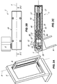
FIGS. 1A, 1B and 1C are respectively a schematic view of an inclined frame S mounted on which is a glass door-leaf A, a lateral and a cross-sectional view along a line plane I C - I C of a first preferred but non-exclusive embodiment of thehinge 1, wherein thecam element 21 is in the initial position; -
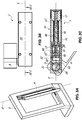
FIGS. 2A, 2B and 2C are respectively a schematic view of an inclined frame S mounted on which is a glass door-leaf A, a lateral and cross-sectional view along a line plane II C - II C of the embodiment of thehinge 1 ofFIG. 1 , wherein thecam element 21 is in the first intermediate working position; -
FIGS. 3A, 3B and 3C are respectively a schematic view of an inclined frame S mounted on which is a glass door-leaf A, a lateral and cross-sectional view along a line plane III C - III C of the embodiment of thehinge 1 ofFIG. 1 , wherein thecam element 21 is in the second intermediate working position; -
FIGS. 4A, 4B and 4C are respectively a schematic view of an inclined frame S mounted on which is a glass door-leaf A, a lateral and cross-sectional view along a line plane IV C - IV C of the embodiment of thehinge 1 ofFIG. 1 , wherein thecam element 21 is in the final position; -
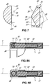
FIG. 5 is an enlarged cross-sectional view of thepin 20 and of theslider 31; -
FIG. 6 is an enlarged cross-sectional view of a further embodiment of thepin 20 and of theslider 31; -
FIG. 7 is an enlarged cross-sectional view of a further embodiment of thepin 20 and of theslider 31; -
FIGS. 8A and 8B are cross-sectional views of a further preferred but non-exclusive embodiment of thehinge 1, respectively in door-open and door-closed position. - With reference to the aforementioned figures, the hinge according to the invention, indicated in their entirety with
number 1, can advantageously be used with closing elements A mounted inclined on a support structure S. - For example, as illustrated in
FIGS. 1A ,2A ,3A and4A , thehinge 1 may be applied to cold stores with inclined doors, or it can be integrated in the tubular frame thereof. - In a further example, the
hinge 1 may be applied to glass door-leaves, such as those of a display window or display case. - Generally, the
hinge 1 is suitable for rotatably coupling a stationary support structure, for example a tubular frame S, and a closing element, for example a door-leaf A, rotatably movable between an opening position, illustrated for example inFIG. 1A , and a closing position, illustrated for example inFIG. 4A , around a rotation axis X. - It should be observed that even though hereinafter reference shall be made to the frame S and the door-leaf D, the
hinge 1 is applicable to any stationary support structure and any closing element, even though not necessarily inclined, without departing from the scope of protection of the attached claims. - Suitably, the
hinge 1 may be a control or hydraulic brake hinge for hydraulically damping the opening or closing displacement of the door-leaf A. However, thehinge 1 may hydraulically brake the closing displacement of the door-leaf A. - It is clear that even though reference hereinafter will be made to the
hinge 1 as acting as a closing control or hydraulic brake hinge, it may also act as an opening control or hydraulic brake hinge without departing from the scope of protection of the attached claims. - The
hinge 1 may include ahinge body 10, may be substantially sheet-like defining a plane, and apin 20 defining the rotation axis X. - It is clear that the closing element A and the stationary support structure S may also rotate around an axis parallel to the axis X without departing from the scope of protection of the attached claims.
- In a preferred but non-exclusive embodiment, the
hinge body 10 may be anchored to the frame S and thepin 20 to the door-leaf A. In such case, thepin 20 may be movable, while thehinge body 10 may be fixed. - On the other hand, the
pin 20 may be fixed and thehinge body 10 may be movable without departing from the scope of protection of the attached claims. - Advantageously, the
hinge body 10 and thepin 20 may be mutually coupled to rotate around the axis X between the door-leaf open A, illustrated for example inFIG. 1A , and the door-leaf closed position A, illustrated for example inFIG. 4A . - In the preferred but non-exclusive embodiment illustrated in the attached figures, the
hinge 1 may open in both directions of rotation of thepin 20. However, it is clear that the hinge may also open in a single direction of rotation without departing from the scope of protection of the attached claims. - Suitably, the
pin 20 may include acam element 21 integrally joined thereto interacting with aslider 11 slidable along an axis Y defined by the working chamber 11' inside thehinge body 10. - Such axis Y may be substantially perpendicular to the axis X. It is clear that the axes X and Y may also be parallel without departing from the scope of protection of the attached claims.
- In any case, the
slider 11 may slide in thehinge body 10 between a retracted end-stop position proximal to thebottom cap 17, illustrated for example inFIG. 1C , and an extended end-stop position distal therefrom, illustrated for example inFIG. 4C . - Such retracted and extended end-stop positions may suitably vary, and not necessarily corresponding to the maximum distal and/or proximal position that can be taken by the
slider 11. - In the preferred but non-exclusive embodiment illustrated in
FIGS. 1A to 4C , ahydraulic chamber 11" filed with oil or other hydraulic damping fluid may be provided for inside theslider 11. - The
hydraulic chamber 11" may be configured according to the disclosures of the international patent application numberPCT/IB2015/050603 , on behalf of the Applicant. Furthermore, such application illustrates the operation of thehydraulic chamber 11" and the relative components. - In particular, according to such disclosures the
hydraulic chamber 11" may include acylinder 60, which may be fixed to thehinge body 10 by means of therod 16. - It is clear that even though described in the present application is a
hinge 1 in which thehydraulic chamber 11" is slidable and thecylinder 60 is stationary, the opposite may also apply, i.e. the cylinder may slide with respect to the working chamber, without departing from the scope of protection of the attached claims. - According to the disclosures of the international patent application number
PCT/IB2015/050603 , thecylinder 60 may divide thehydraulic chamber 11" into a first and a secondvariable volume compartment hydraulic chamber 11", and more in particular it may flow from one to the other of thecompartments hole 14 andvalve pin 15. Valve means 50 for controlling the through-flow of the working fluid between the twocompartments - The hydraulic chamber 11' and the relative components therein may define hydraulic damping means, as better outlined hereinafter.
- In a preferred but non-exclusive embodiment of the invention, elastic means 40, mutually interacting with the
slider 11 may be provided for inside thehinge body 10. - Advantageously, the elastic counteracting means may include, respectively may consist of, a
spiral spring 40 with predetermined diameter. - Even though hereinafter reference will be made to a
spiral spring 40 only, it is clear that any elastic means may be used, just like one or more elastic elements may be used, without departing from the scope of protection of the attached claims. - Suitably, the elastic means 40 may be recovery means, i.e. having a force such to return the
slider 11 from the proximal position to the distal position but not closing or opening the door-leaf A. - However, the recovery elastic means 40 may advantageously be configured and/or dimensioned so as to push the door-leaf A towards the open or closed position, so as to facilitate the user opening or closing the door-leaf A manually.
- In a preferred but non-exclusive embodiment, the
spiral spring 40 may be fitted onto therod 16, which may possibly serve as a guide for the same. - Once the
spiral spring 40 has been fitted onto therod 16, thespring 40 will remain interposed between thebottom cap 17 of thehinge body 10 and therear face 51 of theslider 31, which will act as an abutment face for thespring 40. - On the other hand, the
slider 11 may include a cam follower element 32' with anoperative face 32 and thus interacting with thecam element 21 so that the rotation of the latter around the axis X promotes the sliding of the slider along the axis Y. - Advantageously, the
cam element 21 may be substantially flat. More in particular, in the initial position for example illustrated inFIG. 1C the substantiallyflat cam element 21 may be substantially perpendicular to the axis Y, while in the final position illustrated for example inFIG. 4C it may be substantially parallel to the axis Y. - The
operative face 32 may have a suitable shape, which will allow to control the closing of the door-leaf A from the full opening position illustrated for example inFIG. 1A to the closing position illustrated for example inFIG. 4A . - In particular, thanks to the particular shape of the
operative face 32, the door-leaf A may close at a substantially constant speed, thus that is without banging against the frame S. - The presence of the
spring 40 dimensioned as mentioned above will facilitate the opening of the door-leaf A by the user. As a matter offact 40, thanks to the spring the apparent weight of the opening door-leaf A will be lesser than the actual weight, i.e. the weight that the user would be required to overcome without the spring. - Suitably dimensioning the
spring 40 will allow to reduce the actual weight of the opening door-leaf A up to by 50% of the weight thereof. - Generally, the
operative face 32 may have anoperative portion 33 with at least onefirst section 35' and 35". - The latter may be equal to each other. In particular, the configuration of the
operative face 32 may be symmetrical with respect to the axis Y, so that thehinge 1 behaves in the same way in both directions of rotation of thepin 20. - However, it is clear that the
sections 35', 35" of theoperative face 32 may be configured differently with respect to each other without departing from the scope of protection of the attached claims. - Likewise, it is clear that in case of a hinge opening in only one direction of rotation of the
pin 20 theoperative face 32 may include asingle section 35' or 35" without departing from the scope of protection of the attached claims. - The
sections 35', 35" may be substantially flat and preferably inclined with respect to the axis Y. More in particular, the inclination may be divergent with respect to the axis Y in the direction of thebottom cap 17. - It is clear that, depending on the needs, such sections may for example be slightly curved, without departing from the scope of protection of the attached claims.
- Advantageously, the
operative portion 33 may include asecond section 36 interposed between thefirst sections 35', 35". - Suitably, the
section 36 may be substantially flat. Thus, it may cooperate with the substantiallyflat cam element 21 in the initial position so as to keep the hinge in the closed position, for example as illustrated inFIG. 1A . - It is clear that in case of a hinge opening in a single direction of rotation of the
pin 20, theportion 33, which will not necessarily be in a central position with respect to the cam follower element but for example in a peripheral position, may include only one inclined section and a top section. - Furthermore, depending on the needs, the first sections and the second section may not be necessarily flat, but slightly curved for example.
- The flat or curved top section could also be absent, and it could reduce at a point.
- As particularly illustrated in
FIGS. 1A to 4C , during the closing rotation of the door-leaf A thecam element 21 and the cam follower element 32' interact mutually. - More in particular, as particularly illustrated in
FIGS. 1A to 2C , starting from the fully opened position of the door-leaf A illustrated inFIG. 1A , thecam element 21 will rotate around the axis X for a first angular section to pass from the initial position (FIG. 1C ) to an intermediate working position (FIG. 2C ) in which thecentral portion 22 thereof tilts in thecentral portion 33 of theoperative face 32. - Such rotary movement brings the
end portion 23" of thecam element 21 to contact with theend 37" of thelateral portion 34" of the cam element 32'. The distance d1 taken along the axis Y between thecentral portion 36 and theend 37" will define the aforementioned first angular rotation section, which - in the preferred but non-exclusive embodiment illustrated in the attached figures - may be of about 20°. - During such rotation the
slider 11 will remain stationary with respect to thehinge body 10, so that the corresponding rotation of the door-leaf A is substantially free, i.e. non-braked. - Subsequently, the
cam element 21 will continue to rotate around the axis X for a further second angular section, which may for example be of about 40°. Such movement will bring thecam element 21, along with the door-leaf A, from the first intermediate working position (FIG. 2C ) to a second intermediate working position (FIG. 3C ). - During such second rotation step, the
end portion 23" of thecam element 21 may exclusively rest against thelateral portion 34" of the cam element 32', up to impacting against thecentral portion 33. - Thus, the second rotation step of the
cam element 21 will displace theslider 11 along the axis Y, promoting the through-flow of the working fluid fromcompartment 12 tocompartment 13 through the calibrated passage defined between thehole 14 and thevalve pin 15. Thus, the movement of the door-leaf A around the axis X will be hydraulically damped with a first predetermined resistance strength. - The length of the
lateral portion 34" of the cam element 32' against which theend portion 23" of thecam element 21 rests, i.e. substantially the distance d2 between theends 37' and 37", may define the second angular section of the rotation of the door-leaf A. - Subsequently, the
cam element 21 will continue to rotate around the axis X for a further third angular section, which may for example be of about 30°. Such movement will bring thecam element 21, along with the door-leaf A, from the second intermediate working position (FIG. 3C ) to the final position (FIG. 4C ). - During the third rotation step, the
end portion 23" of thecam element 21 may exclusively rest against thecentral portion 33 of the cam follower element 32', and more in particular against thesection 35" thereof. - The length of the latter, i.e. substantially the distance d3 between the
ends 37' and 37"', may define the third angular section of the rotation of the door-leaf A. - Given the particular conformation of the
central portion 33, such rotary movement will considerably increase the pressure of the working fluid inside thehydraulic chamber 11" with respect to the pressure that develops during the second rotation step. Thus, the movement of the door-leaf A around the axis X will be hydraulically damped with a second resistance strength greater than the first resistance strength which develops during the second rotation step. - Thanks to the mutual configuration of the
cam elements 21 andcam follower elements 32 mentioned above, the closing rotation of the door-leaf A may occur at a substantially constant speed. - In a preferred but non-exclusive embodiment, the
cam element 21 may have a predetermined distance d5 from the axis X. - In this manner, the
central portion 33 in the final portion (FIG. 4C ) will act against thecam element 21 to force the closing door-leaf A against the frame S. Such configuration may be particularly useful to promote the mutual interaction between thecam element 21 and the cam follower element 32' substantially for the entire opening and/or closing rotation of the door-leaf A. - In the embodiment described above, the damping means that supply the resistance strength to the weight force A during the rotation are of the hydraulic type.
- In an alternative embodiment, for example illustrated in
FIGS. 8A and 8B , the damping means that supply the resistance strength to the weight force of the door-leaf A during the rotation may be of the mechanical type. - More in particular, such mechanical damping means may include or consist of a compression spring 40'.
- Such spring may have characteristics such to supply the aforementioned resistance strength. More in particular, the compression spring 40' may have a high rigidity, for example of at least 10 Kgf / mm.
- In the present document, the expression rigidity of a compression spring is used to indicate the force required to compress the length unit, for example expressed in kilogram-force per compression millimetre of the spring.
- The
slider 11 may be defined by a solid cylinder which includes the cam follower element 32'. - The spring 40' may be interposed between the
slider 11 and thehinge body 10. More in particular, the spring 40' may be interposed between theslider 11 and thebottom cap 17 of the latter. The working chamber 11' may be without therod 16. - All the other characteristics of the embodiment of the
hinge 1 ofFIGS. 8A and 8B may be identical to those of the embodiment of thehinge 1 ofFIGS. 1A to 4C . In particular, the configuration of thecam element 21 and that of the cam follower element 32' may be identical. - The operation may also be substantially be the same one described above, except for the fact that the resistance strength is given by the progressive compression of the spring 40'.
- In light of the above, it is clear that the hinge according to the invention attains the pre-set objectives.
- The hinge according to the invention is susceptible to numerous modifications and variants all falling within the inventive concept outlined in the attached claims. All details can be replaced by other technically equivalent elements, and the materials can be different depending on the technical needs, without departing from the scope of protection of the invention.
- Even though the hinge has been described with reference to the attached figures, the reference numbers utilised in the description and in the claims are meant for improving the intelligibility of the invention and thus do not limit the claimed scope of protection in any manner whatsoever.
Claims (15)
- A hinge for the opening and/or closing control of a closing element (A) anchored to a stationary support structure (S), such as a wall, a frame or a floor, in particular for inclined doors or door-leaves (A), the hinge comprising:- a hinge body (10) anchorable to one of the closing element (A) and the stationary support structure (S) said hinge body (10) internally comprising at least one working chamber (11') defining a first longitudinal axis (Y);- a pin (20) defining a second longitudinal axis (X) anchorable to the other of the closing element (A) and the stationary support structure (S), said pin (20) and said hinge body (10) being mutually coupled to each other to rotate relatively with respect to each other around said second axis (X) or around an axis parallel thereto;- at least one slider element (11) inserted in said at least one working chamber (11');wherein said pin (20) includes a cam element (21) integrally rotatable therewith, said slider element (11) comprising a cam follower element (32') interacting with said cam element (21) so that during said opening and/or closing mutual rotation between said pin (20) and said hinge body (10) around said second axis (X) corresponds to the sliding of said slider element (11) along said first axis (Y), damping means being provided for mutually interacting with said slider element (11) during the displacement thereof;
wherein said cam follower element (32') has at least one first operative portion (33) with a first end area (37') proximal to said second axis (X) and a second opposite end area (37") distal therefrom, said cam element (21) having at least one second operative portion (22) and at least one third operative portion (23") mutually configured so that during said mutual opening and/or closing rotation between said pin (20) and said hinge body (10) around said second axis (X):- for a first angular section, said at least one second operative portion (22) rotates on said first end area (37') from an initial working position to a first intermediate working position wherein said at least one third operative portion (23") comes into contact with said second end area (37"), so that said slider element (11) remains substantially stationary and so that the rotation of the closing element (A) is substantially non-braked;- for a second angular section, said cam element (21) rotates around said second axis (X) exclusively with said at least one third operative portion (23") in contact with said at least one first operative portion (33) to pass from said first intermediate working position to a final working position wherein said at least one third operative portion (23") is in proximity or in contact with said first end area (37'), so as to promote the sliding of said slider element (11) along said first axis (Y) and the consequent damping of the rotation of the closing element (A) with a predetermined resistance strength. - Hinge according to claim 1, wherein said first and second end areas (37', 37") have a first mutual distance (d1) along said first axis (Y) defining said first angular section.
- Hinge according to claim 1 or 2, wherein said first and second end areas (37', 37") have a second distance (d2) defining said second angular section of the rotation of said cam element (21).
- Hinge according to claim 1, 2 or 3, wherein said at least one first operative portion (33) has at least one first section (35', 35") substantially inclined with respect to said first axis (Y), said at least one first section (35', 35") being interposed between said first and second end areas (37', 37"), said at least one first section (35', 35") being preferably flat or slightly curved.
- Hinge according to any one of the preceding claims, wherein said cam element (21) is substantially flat or slightly curved, said flat or slightly curved cam element (21) in said initial position being preferably substantially perpendicular to said first axis (Y) and in said final position it is substantially parallel to said first axis (Y).
- Hinge according to claim 5, wherein said at least one first operative portion (33) has at least one second section (36) adjacent to said at least one first section (35', 35") which includes or which defines said first end area (37'), said second section (36) being substantially counter-shaped with respect to said cam element (21) so as to cooperate therewith to keep the hinge in the closed and/or open position in said initial position.
- Hinge according to any one of the preceding claims, wherein said at least one first operative portion (33) has at least one third section (34', 34") adjacent to said at least one first section (35', 35") which includes or which defines said second end area (37"), said at least one third operative portion (23") during said second angular section coming in contact first with said third section (34', 34") and then with said first section (35', 35") of said cam follower element (32'), said at least one third section (34', 34") preferably being substantially inclined with respect to said at least one first section (35', 35") so that the first resistance strength due to the interaction between said at least one third operative portion (23") and said third section (34', 34") is different with respect to the second resistance strength due to the interaction between the at least one third operative portion (23") and said first section (35', 35"), said second resistance strength preferably being greater than said first resistance strength.
- Hinge according to the preceding claim, wherein said at least one third section (34', 34") of said cam follower element (32') is substantially flat, said at least one third section (34', 34") being preferably substantially perpendicular to said first axis (Y).
- Hinge according to claim 7 or 8, wherein said at least one first operative portion (33) has a third end area (37") interposed between said at least one third section (34', 34") and at least one first section (35', 35"), said second and third end areas (37", 37"') having a third distance (d3) defining the portion of said second angular section wherein the rotation of the closing element (A) is hydraulically damped with said first resistance strength, said first and third end areas (37', 37"') having a fourth distance (d4) defining the portion of said second angular section wherein the rotation of the closing element (A) is damped with said second resistance strength.
- Hinge according to one or more of the preceding claims, wherein said cam element (21) and said cam follower element (32) are mutually configured so that during said mutual opening and/or closing rotation the speed of said closing element (A) is substantially constant.
- Hinge according to any one of the preceding claims, wherein said cam element (21) has a fifth predetermined distance (d5) from said second axis (X), so as to interact with said cam follower element (32') substantially for the entire opening and/or closing rotation of said closing element (A).
- Hinge according to any one of the preceding claims, further comprising recovery elastic means (40) acting on said slider element (11) to return it to its initial position subsequently to said mutual opening and/or closing rotation.
- Hinge according to any one of the preceding claims, wherein said damping means are of mechanical type and include at least one compression spring (40'), the latter preferably having a rigidity of at least 10 Kgf / mm.
- Hinge according to any one of claims 1 to 12, wherein said damping means are of the hydraulic type and include:- a hydraulic damping fluid, preferably oil;- a hydraulic circuit (12, 13, 14) in which said hydraulic damping fluid circulates;- control means (50) inserted in said hydraulic circuit (12, 13, 14) to control the circulation of said hydraulic damping fluid during the displacement of said slider element (11);so as to hydraulically damp the mutual opening and/or closing rotation of said pin (20) and of said hinge body (10).
- A system comprising:- a stationary support structure (S), such as for example a wall, a frame or a floor;- at least one closing element (A) rotatably mounted on said stationary support structure (S) to rotate around a rotation axis (X), said stationary support structure (S) being configured so that said rotation axis (X) is inclined with respect to a vertical axis;- at least one hinge (1) interposed between said stationary support structure (S) and said at least one closing element (A), said at least one hinge (1) being the control hinge according to one or more of the preceding claims.
Applications Claiming Priority (1)
| Application Number | Priority Date | Filing Date | Title |
|---|---|---|---|
| IT102018000004608A IT201800004608A1 (en) | 2018-04-17 | 2018-04-17 | CONTROL HINGE FOR INCLINED DOORS OR LEAVES |
Publications (1)
| Publication Number | Publication Date |
|---|---|
| EP3556980A1 true EP3556980A1 (en) | 2019-10-23 |
Family
ID=62875204
Family Applications (1)
| Application Number | Title | Priority Date | Filing Date |
|---|---|---|---|
| EP19169402.5A Pending EP3556980A1 (en) | 2018-04-17 | 2019-04-16 | Hinge for controlling inclined doors or door-leaves |
Country Status (2)
| Country | Link |
|---|---|
| EP (1) | EP3556980A1 (en) |
| IT (1) | IT201800004608A1 (en) |
Cited By (1)
| Publication number | Priority date | Publication date | Assignee | Title |
|---|---|---|---|---|
| US11261637B2 (en) * | 2016-12-15 | 2022-03-01 | In & Tec S.R.L. | Hinge for the rotatable movement of a door, a shutter or the like |
Citations (4)
| Publication number | Priority date | Publication date | Assignee | Title |
|---|---|---|---|---|
| EP2071993A2 (en) * | 2007-12-17 | 2009-06-24 | Altura Leiden Holding B.V. | Partition |
| AU2010100487A4 (en) * | 2009-08-18 | 2010-07-08 | Chung Chow | Damped door hinge |
| WO2012049518A1 (en) * | 2010-10-14 | 2012-04-19 | Chung Chow | Hinge having self centering means |
| GB2525444A (en) * | 2014-04-25 | 2015-10-28 | Bestko Prec Ltd | Damped Hinge |
-
2018
- 2018-04-17 IT IT102018000004608A patent/IT201800004608A1/en unknown
-
2019
- 2019-04-16 EP EP19169402.5A patent/EP3556980A1/en active Pending
Patent Citations (4)
| Publication number | Priority date | Publication date | Assignee | Title |
|---|---|---|---|---|
| EP2071993A2 (en) * | 2007-12-17 | 2009-06-24 | Altura Leiden Holding B.V. | Partition |
| AU2010100487A4 (en) * | 2009-08-18 | 2010-07-08 | Chung Chow | Damped door hinge |
| WO2012049518A1 (en) * | 2010-10-14 | 2012-04-19 | Chung Chow | Hinge having self centering means |
| GB2525444A (en) * | 2014-04-25 | 2015-10-28 | Bestko Prec Ltd | Damped Hinge |
Cited By (1)
| Publication number | Priority date | Publication date | Assignee | Title |
|---|---|---|---|---|
| US11261637B2 (en) * | 2016-12-15 | 2022-03-01 | In & Tec S.R.L. | Hinge for the rotatable movement of a door, a shutter or the like |
Also Published As
| Publication number | Publication date |
|---|---|
| IT201800004608A1 (en) | 2019-10-17 |
Similar Documents
| Publication | Publication Date | Title |
|---|---|---|
| EP1538293B1 (en) | Combination of a damping device with hinges for pieces of furniture | |
| EP2426300B1 (en) | Door closing hinge, particularly for glass doors | |
| RU2500870C2 (en) | Piece of furniture with pushing device for mobile parts of furniture | |
| EP3575532B1 (en) | Lifting system for leaves of furniture | |
| CN1715605B (en) | Disappearing hinging device for windows and doors with wing and swivel wing opening | |
| EP3309336B1 (en) | Snap hinge with damped closing | |
| EA028990B1 (en) | Door hinge | |
| EP1501992A1 (en) | Multi-link hinge | |
| JP2002227513A (en) | Lifting device for folding double door | |
| US5533234A (en) | Torsion hinge with tubular pivot pin | |
| JP2020502404A5 (en) | ||
| EP3555399B1 (en) | Hinge for the rotatable movement of a door, a shutter or the like | |
| EP3556980A1 (en) | Hinge for controlling inclined doors or door-leaves | |
| EP3052730B1 (en) | Hinge device for doors, shutters or the like | |
| CN108166878A (en) | A kind of orientable hidden type hydraulic hinge | |
| CN208056900U (en) | A kind of Pinless hinge with guide member with buffer unit | |
| AU2017287706B2 (en) | A hinge mechanism and a hinge assembly | |
| CN108049748A (en) | A kind of Pinless hinge with guide member with buffer unit | |
| KR101784984B1 (en) | Folding door with fuction of speed control and auto-moving | |
| DE10001424A1 (en) | Door with door leaf mounted on hinge plate has damper and energy saver, with glide rail and slide arm. | |
| WO2023156893A1 (en) | Hinge for doors or swing shutter, in particular for refrigerated cabinets, as well as a system that includes this hinge | |
| IT201900006586A1 (en) | HINGE FOR THE ROTATING HANDLING OF A DOOR, A LEAF OR SIMILAR | |
| EP1255015A2 (en) | Door closure mechanism | |
| ITBO940148U1 (en) | SWINGING GATE | |
| ITMI20081049A1 (en) | SHOCK ABSORBER DEVICE FOR FURNISHING ELEMENTS HINGES |
Legal Events
| Date | Code | Title | Description |
|---|---|---|---|
| PUAI | Public reference made under article 153(3) epc to a published international application that has entered the european phase |
Free format text: ORIGINAL CODE: 0009012 |
|
| STAA | Information on the status of an ep patent application or granted ep patent |
Free format text: STATUS: THE APPLICATION HAS BEEN PUBLISHED |
|
| AK | Designated contracting states |
Kind code of ref document: A1 Designated state(s): AL AT BE BG CH CY CZ DE DK EE ES FI FR GB GR HR HU IE IS IT LI LT LU LV MC MK MT NL NO PL PT RO RS SE SI SK SM TR |
|
| AX | Request for extension of the european patent |
Extension state: BA ME |
|
| STAA | Information on the status of an ep patent application or granted ep patent |
Free format text: STATUS: REQUEST FOR EXAMINATION WAS MADE |
|
| 17P | Request for examination filed |
Effective date: 20200423 |
|
| RBV | Designated contracting states (corrected) |
Designated state(s): AL AT BE BG CH CY CZ DE DK EE ES FI FR GB GR HR HU IE IS IT LI LT LU LV MC MK MT NL NO PL PT RO RS SE SI SK SM TR |
|
| STAA | Information on the status of an ep patent application or granted ep patent |
Free format text: STATUS: EXAMINATION IS IN PROGRESS |
|
| 17Q | First examination report despatched |
Effective date: 20231026 |