EP3556620A1 - Control valve for a compressed air system - Google Patents
Control valve for a compressed air system Download PDFInfo
- Publication number
- EP3556620A1 EP3556620A1 EP19166192.5A EP19166192A EP3556620A1 EP 3556620 A1 EP3556620 A1 EP 3556620A1 EP 19166192 A EP19166192 A EP 19166192A EP 3556620 A1 EP3556620 A1 EP 3556620A1
- Authority
- EP
- European Patent Office
- Prior art keywords
- sealing ring
- control piston
- sealing
- control valve
- piston
- Prior art date
- Legal status (The legal status is an assumption and is not a legal conclusion. Google has not performed a legal analysis and makes no representation as to the accuracy of the status listed.)
- Granted
Links
- 238000007789 sealing Methods 0.000 claims abstract description 119
- 238000013022 venting Methods 0.000 claims description 25
- 238000004891 communication Methods 0.000 claims description 3
- 230000006835 compression Effects 0.000 description 8
- 238000007906 compression Methods 0.000 description 8
- 230000001419 dependent effect Effects 0.000 description 2
- 238000010276 construction Methods 0.000 description 1
- 238000009795 derivation Methods 0.000 description 1
- 238000009423 ventilation Methods 0.000 description 1
Images


Classifications
-
- B—PERFORMING OPERATIONS; TRANSPORTING
- B60—VEHICLES IN GENERAL
- B60T—VEHICLE BRAKE CONTROL SYSTEMS OR PARTS THEREOF; BRAKE CONTROL SYSTEMS OR PARTS THEREOF, IN GENERAL; ARRANGEMENT OF BRAKING ELEMENTS ON VEHICLES IN GENERAL; PORTABLE DEVICES FOR PREVENTING UNWANTED MOVEMENT OF VEHICLES; VEHICLE MODIFICATIONS TO FACILITATE COOLING OF BRAKES
- B60T15/00—Construction arrangement, or operation of valves incorporated in power brake systems and not covered by groups B60T11/00 or B60T13/00
- B60T15/02—Application and release valves
- B60T15/18—Triple or other relay valves which allow step-wise application or release and which are actuated by brake-pipe pressure variation to connect brake cylinders or equivalent to compressed air or vacuum source or atmosphere
- B60T15/182—Trailer brake valves
-
- B—PERFORMING OPERATIONS; TRANSPORTING
- B60—VEHICLES IN GENERAL
- B60T—VEHICLE BRAKE CONTROL SYSTEMS OR PARTS THEREOF; BRAKE CONTROL SYSTEMS OR PARTS THEREOF, IN GENERAL; ARRANGEMENT OF BRAKING ELEMENTS ON VEHICLES IN GENERAL; PORTABLE DEVICES FOR PREVENTING UNWANTED MOVEMENT OF VEHICLES; VEHICLE MODIFICATIONS TO FACILITATE COOLING OF BRAKES
- B60T15/00—Construction arrangement, or operation of valves incorporated in power brake systems and not covered by groups B60T11/00 or B60T13/00
- B60T15/02—Application and release valves
- B60T15/025—Electrically controlled valves
- B60T15/027—Electrically controlled valves in pneumatic systems
-
- B—PERFORMING OPERATIONS; TRANSPORTING
- B60—VEHICLES IN GENERAL
- B60T—VEHICLE BRAKE CONTROL SYSTEMS OR PARTS THEREOF; BRAKE CONTROL SYSTEMS OR PARTS THEREOF, IN GENERAL; ARRANGEMENT OF BRAKING ELEMENTS ON VEHICLES IN GENERAL; PORTABLE DEVICES FOR PREVENTING UNWANTED MOVEMENT OF VEHICLES; VEHICLE MODIFICATIONS TO FACILITATE COOLING OF BRAKES
- B60T15/00—Construction arrangement, or operation of valves incorporated in power brake systems and not covered by groups B60T11/00 or B60T13/00
- B60T15/02—Application and release valves
- B60T15/18—Triple or other relay valves which allow step-wise application or release and which are actuated by brake-pipe pressure variation to connect brake cylinders or equivalent to compressed air or vacuum source or atmosphere
- B60T15/181—Trailer control valves
-
- F—MECHANICAL ENGINEERING; LIGHTING; HEATING; WEAPONS; BLASTING
- F16—ENGINEERING ELEMENTS AND UNITS; GENERAL MEASURES FOR PRODUCING AND MAINTAINING EFFECTIVE FUNCTIONING OF MACHINES OR INSTALLATIONS; THERMAL INSULATION IN GENERAL
- F16J—PISTONS; CYLINDERS; SEALINGS
- F16J15/00—Sealings
- F16J15/16—Sealings between relatively-moving surfaces
- F16J15/32—Sealings between relatively-moving surfaces with elastic sealings, e.g. O-rings
- F16J15/3204—Sealings between relatively-moving surfaces with elastic sealings, e.g. O-rings with at least one lip
- F16J15/3232—Sealings between relatively-moving surfaces with elastic sealings, e.g. O-rings with at least one lip having two or more lips
- F16J15/3236—Sealings between relatively-moving surfaces with elastic sealings, e.g. O-rings with at least one lip having two or more lips with at least one lip for each surface, e.g. U-cup packings
Definitions
- the invention relates to a control valve of a compressed air system of a vehicle, with at least one control piston, which is guided axially movable in a housing-fixed cylinder, wherein by means of the control piston, sealed via at least one arranged on the outer circumference of the control piston sealing ring, two pressure chambers are separated from each other.
- control valves are frequently used with at least one axially guided in a housing-fixed cylinder control piston.
- the control piston separates, sealed by means of at least one arranged on the outer circumference of the control piston sealing ring, two pressure chambers from each other.
- One of the pressure chambers is usually a working pressure chamber which is connected to a working pressure connection of a consumer and, depending on the axial position of the control piston, can be connected to a supply pressure connection or a venting outlet or can be shut off from both.
- the other pressure chamber may be a control pressure chamber or a compensation chamber communicating with the environment via a ventilation bore.
- the control piston can be adjusted to adjust its axial position mechanically, pneumatically or electromagnetically.
- a piston-type control valve may be used as a towing vehicle brake valve, a trailer control valve, a trailer brake valve, or a relay valve.
- a relay valve of a compressed air brake system with a pneumatically adjustable control piston is known in which the control piston is guided axially movable in a cylinder of a valve housing and a working pressure chamber separates from a control pressure chamber.
- the control pressure chamber can be acted upon by a solenoid valve alternately with a control pressure or pressure switchable.
- a radial sealing ring is used with a trained as an outer annular web attachment web in a groove formed as an annular groove in the inner wall of the cylinder, and the piston is provided with a correspondingly long, effective as a sealing surface cylindrical outer wall.
- a similar relay valve of a pneumatic brake system with a pneumatically adjustable control piston is also from the DE 10 20014 009 179 A1 known.
- the control piston is guided axially movable in a cylinder of a valve housing and also separates here a working pressure chamber from a control pressure chamber.
- a Z-shaped profiled sealing ring is inserted into an annular groove which is formed in the cylindrical outer wall of the control piston.
- For its axial guidance of the control piston is mounted by means of a central guide sleeve slidably mounted on a bearing pin fixed to the housing.
- control piston of the known control valves Due to their sliding over a central guide sleeve or a central bearing journal, the control piston of the known control valves each have an unfavorable large axial height, which in particular increases the axial dimensions of the respective control valve.
- sealing of the separated by the respective control piston pressure chambers by means of only one arranged on the outer circumference of the control piston sealing ring in the two latter embodiments of the known control valves is relatively weak.
- the present invention is therefore based on the object to propose a spool with a less axial space-requiring radial guidance and with an improved seal of the separated by the control piston pressure chambers in a piston constructed in the control valve of the type mentioned.
- the sealing ring is designed as a radial sealing ring with a substantially the axial thickness of the control piston corresponding axial width, that the sealing ring at its two axial edges in each case a radially obliquely outwards directed, abutting the inner wall of the cylinder sealing lip, and that a plurality of circumferentially distributed guide body are formed between the two sealing lips on the sealing ring.
- the invention is therefore based on a known control valve of a compressed air system of a vehicle, with at least one control piston which is guided axially movable in a housing-fixed cylinder, wherein by means of the control piston, sealed via at least one arranged on the outer circumference of the control piston sealing ring, two pressure chambers separated from each other are
- the sealing ring is designed as a radial sealing ring whose axial width substantially corresponds to the axial thickness of the control piston.
- the sealing ring in each case has a radially obliquely outwardly directed, on the inner wall of the cylinder acting as a sealing surface sealing lip, so that the separated by the control piston pressure chambers are well sealed against each other.
- Between the two sealing lips of the sealing ring are several arranged distributed circumferentially guide body or at least one circumferential guide body, by means of which the control piston is slidably guided on the inner wall of the housing-fixed cylinder.
- the sealing ring For its stable attachment to the control piston, the sealing ring according to a development on its inner side designed as a radial annular groove mounting groove which engages in the assembled state arranged on the outer circumference of the control piston, designed as a radial annular web attachment web.
- these guide bodies are preferably designed as radially raised, round guide knobs with radially outer cylindrical sliding surface, which are arranged axially centrally between the sealing lips.
- the guide body of the sealing ring is formed as a radially raised annular land with an outer cylindrical sliding surface, which is arranged axially centrally between the sealing lips and circumferentially related interruptions.
- an annular venting space via at least one arranged in the sealing ring radial vent hole with a between the sealing lips of the sealing ring and the inner wall of the Cylinder enclosed gap and with a arranged in the control piston vent passage is in communication.
- the annular venting space is preferably bounded by a radial annular groove, which is formed axially centrally in the bottom wall of the fastening groove of the sealing ring.
- annular vent space is bounded by a radial annular groove, which is formed axially centrally in the outer wall of the fastening web of the control piston.
- the vent holes in the sealing ring expediently largely circumferentially arranged centrally between the guide bodies to allow an unobstructed inflow of compressed air penetrated into the intermediate space from both axial directions.
- sealing ring with a circumferential, annular web-shaped guide body is provided that this interrupted in the vent holes of the sealing ring to allow an unobstructed inflow of compressed air penetrated into the intermediate space from both axial directions.
- the vent passage is preferably formed as a cylindrical pipe or as a ring-cylindrical pipe, which is formed centrally in or coaxially with the central axis of the control piston in the same.
- the annular venting space is then connected to the venting channel via at least one radial venting bore formed in the control piston.
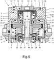
- Fig. 5 is shown in a section of a central section through a valve unit 1, which has two constructed in piston construction control valves 2, 3.
- the valve unit 1 can be used, for example, in a pneumatic brake system of a motor vehicle with two brake circuits as a trailer control valve or as a trailer brake valve.
- the valve unit 1 has a valve housing 4 which comprises an upper housing part 5 and a lower housing part 6 which are connected to one another.
- stepped cylindrical interior a largely pot-cylindrical upper housing insert 7 and a largely pot-cylindrical lower housing insert 8 are arranged immovably.
- first control valve 2 is disposed in the upper part of the valve housing 4 and has a control piston 9 and a cooperating with this sealing piston 11 of an upper seat valve 10.
- the control piston 9 is axially movably guided in a cylinder 12 of the upper housing part 5, is loaded axially upward from a compression spring 13, which is supported on a shoulder 54 of the upper housing part 5, and has on its underside a ring-shaped inner valve seat 14 of the upper seat valve 10.
- the sealing piston 11 of the upper poppet valve 10 is axially movably guided on a cylindrical guide portion 15 of the upper housing insert 7 and of a coil spring designed as a compression spring 16 which is supported on the upper housing insert 7, axially upwards in the direction of a housing upper part 5 arranged annular ridge outer Valve seat 17 loaded.
- An enclosed by the control piston 9 in the cylinder 12 of the upper housing part 5 working pressure chamber 19 to which, for example, a leading to the wheel brake cylinders of a brake circuit brake line can be connected, is dependent on the axial position of the control piston 9 with a below the outer valve seat 17 between the upper housing part 5 and the upper housing insert 7 located annular supply pressure chamber 20 or via a central vent passage 18 with a valve housing 4 in the bottom center venting pressure chamber 21 connectable or shut off against these two pressure chambers 20, 21.
- the vent passage 18 is centrally formed in and coaxial with the center axis 53 of the control piston 22 in the same.
- the working pressure chamber 19 When the control piston 9 rests with its inner valve seat 14 on the sealing piston 11 of the upper seat valve 10 and has pushed away from the outer valve seat 17, the working pressure chamber 19 is connected to the supply pressure chamber 20 communicating with a compressed air source or a supply pressure line, so that the Working pressure in the working pressure chamber 19 is increased. If the control piston 9 has lifted with its inner valve seat 14 from the sealing piston 11 of the upper seat valve 10, and the sealing piston 11 rests against the outer valve seat 17, the working pressure chamber 19 is connected to the non-illustrated muffler with the environment in connection venting pressure chamber 21st connected, so that the working pressure in the working pressure chamber 19 is reduced.
- This in Fig. 5 completely mapped second control valve 3 is arranged in the lower part of the valve housing 4 and has a control piston 22 and a cooperating with this sealing piston 24 of a lower seat valve 23.
- the control piston 22 is axially movably guided in a cylinder 25 of the upper housing insert 7, is loaded by a coil spring designed as a compression spring 26 which is supported on the lower housing insert 8 upwards, and has on its underside a ring-web-shaped inner valve seat 27 of the lower seat valve 23 on.
- the sealing piston 24 of the lower seat valve 23 is axially movably guided on a cylindrical guide section 28 of the lower housing part 6 and by a coil spring designed as a compression spring 29 which is supported on the lower housing part 6 upwards in the direction of a arranged in the lower housing insert 8 annular web-shaped outer valve seat 30th loaded.
- An enclosed by the control piston 22 in the cylinder 25 of the upper housing insert 7 working pressure chamber 32 is dependent on the axial position of the control piston 22 with a located below the outer valve seat 30 between the lower housing insert 8 and the lower housing part 6 annular supply pressure chamber 33 or via a central opening 31st in the sealing piston 24 of the lower seat valve 23 connected to the venting pressure chamber 21 or against two pressure chambers 21, 33 shut off.
- the axial position of the control piston 22 can be adjusted by appropriately setting a control pressure effective in a control pressure space 34, for example by means of a solenoid valve.
- the control pressure chamber 34 is the working pressure chamber 32 axially enclosed by the control piston 22 in the cylinder 25 of the upper housing insert 7.
- the working pressure chamber 32 is connected to the supply pressure chamber 33 communicating with a compressed air source, so that the working pressure in the Working pressure chamber 32 is increased.
- the control piston 22 of the second control valve 3 has at the top a central tubular body 35 and below a circular disk-shaped piston body 36, which are integrally connected to each other. Within the tubular body 35 is the vent channel 18 of the first control valve 2.
- the piston body 36 separates the control pressure chamber 34 from the working pressure chamber 32 and has for sealing a arranged on its outer circumference sealing ring 37, 37 '.
- the sealing ring 37, 37 ' is formed as a radial sealing ring with a substantially the thickness of the piston body 36 corresponding axial width.
- the sealing ring 37, 37 ' has at its two axial edges in each case a radially obliquely outwardly directed first or second sealing lip 39, 40, which bear against the effective inner surface as a sealing surface 38 of the cylinder 25 of the upper housing insert 7. Between the two sealing lips 39, 40 of the sealing ring 37, 37 'with a plurality of circumferentially distributed arranged guide bodies 50 or with a circumferential guide body 51, which in Fig. 5 are not visible.
- control piston 22 is thus also on the sealing ring 37, 37 'radially guided ,
- annular venting chamber 46, 47 is formed, which has a plurality of in the sealing ring 37, 37' formed radial vent holes 45 is connected to a between the two sealing lips 39, 40 of the sealing ring 37, 37 'and the inner wall 38 of the cylinder 25 of the upper housing insert 7 enclosed space 44 and a valve disposed in the control piston 22 vent 49 in conjunction.
- the vent channel 49 is formed as a ring-cylindrical pipe, which is arranged in the lower part of the control piston 22 coaxially around the central tubular body 35 and closed at the top, and which opens downwardly open into the venting pressure chamber 21.
- the annular venting chamber 46, 47 communicates with the venting channel 49 via a plurality of radial venting bores 48 arranged in the piston body 36.
- FIG. 1 has the sealing ring 37 axially centrally between the two sealing lips 39, 40 a plurality of exemplary present four circumferentially distributed arranged guide body 50, which are formed as radially raised and round guide knobs, each with radially outer cylindrical sliding surfaces.
- the circumference largely centrally between each two adjacent guide bodies 50, a respective radial vent hole 45 is formed in the sealing ring 37, so that an inflow of about both sealing lips 39, 40 penetrated into the intermediate space 44 compressed air to the vent holes 45 is possible.
- the sealing ring 37 'axially centrally between the two sealing lips 39, 40 a circumferential guide body 51 which is formed as a radially raised annular land with an outer cylindrical sliding surface.
- this guide body 51 consists of several comparatively long ring land segments, which are slightly spaced from each other by interruptions 52.
- Distributed on the circumference are a plurality of exemplary four radial vent holes 45 formed in the sealing ring 37 ', in the region of the guide body 51 is interrupted in each case to allow an inflow of over both sealing lips 39, 40 penetrated into the gap 44 compressed air.
- annular venting space 46 is formed as a radial annular groove which is axially centrally formed in the bottom wall of the fastening groove 42 of the sealing ring 37, 37 '.
- the arranged in the sealing ring 37, 37 'vent holes 45 are characterized relatively short.
- annular venting chamber 47 is formed by a radial annular groove, which is formed axially centrally in the outer wall of the fastening web 43 of the control piston 22.
- the arranged in the sealing ring 37, 37 'vent holes 45 are therefore made slightly longer with a thicker sealing ring wall.
Landscapes
- Engineering & Computer Science (AREA)
- Transportation (AREA)
- Mechanical Engineering (AREA)
- Valves And Accessory Devices For Braking Systems (AREA)
Abstract
Die Erfindung betrifft ein Steuerventil (3) einer Druckluftanlage eines Fahrzeugs, mit mindestens einem Steuerkolben (22), der axialbeweglich in einem gehäusefesten Zylinder (25) geführt ist, wobei mittels dem Steuerkolben (22), abgedichtet über mindestens einen am Außenumfang des Steuerkolbens (22) angeordneten Dichtring (37), zwei Druckräume (32, 34) voneinander getrennt sind. Zur Verbesserung der radialen Führung des Steuerkolbens (22) und der Abdichtung der durch den Steuerkolben (22) getrennten Druckräume (32, 34) ist vorgesehen, dass der Dichtring (37) als ein Radialdichtring mit einer weitgehend der axialen Dicke des Steuerkolbens (22) entsprechenden axialen Breite ausgebildet ist, dass der Dichtring (37) an seinen beiden axialen Rändern jeweils eine radial schräg nach außen gerichtete, an der Innenwand (38) des Zylinders (25) anliegende Dichtlippe (39, 40) aufweist, und dass zwischen den beiden Dichtlippen (39, 40) an dem Dichtring (37) mehrere umfangsseitig verteilt angeordnete Führungskörper (50) ausgebildet sind.The invention relates to a control valve (3) of a compressed-air system of a vehicle, having at least one control piston (22) which is axially movably guided in a cylinder (25) fixed to the housing, wherein by means of the control piston (22), sealed via at least one on the outer circumference of the control piston (22). 22) arranged sealing ring (37), two pressure chambers (32, 34) are separated from each other. To improve the radial guidance of the control piston (22) and the sealing of the control piston (22) separate pressure chambers (32, 34) it is provided that the sealing ring (37) as a radial sealing ring with a substantially the axial thickness of the control piston (22) is formed corresponding axial width, that the sealing ring (37) at its two axial edges in each case a radially obliquely outwardly, on the inner wall (38) of the cylinder (25) abutting sealing lip (39, 40), and that between the two Sealing lips (39, 40) on the sealing ring (37) a plurality of circumferentially distributed arranged guide body (50) are formed.
Description
Die Erfindung betrifft ein Steuerventil einer Druckluftanlage eines Fahrzeugs, mit mindestens einem Steuerkolben, der axialbeweglich in einem gehäusefesten Zylinder geführt ist, wobei mittels dem Steuerkolben, abgedichtet über mindestens einen am Außenumfang des Steuerkolbens angeordneten Dichtring, zwei Druckräume voneinander getrennt sind.The invention relates to a control valve of a compressed air system of a vehicle, with at least one control piston, which is guided axially movable in a housing-fixed cylinder, wherein by means of the control piston, sealed via at least one arranged on the outer circumference of the control piston sealing ring, two pressure chambers are separated from each other.
Straßenfahrzeuge, insbesondere schwere Nutzfahrzeuge und Schienenfahrzeuge, sind häufig mit einer Druckluftversorgungsanlage ausgerüstet, von der Druckluft-Verbraucherkreise, wie Betriebsbremskreise, ein Feststellbremskreis, ein Luftfederungskreis, ein Niveauregelungskreis und/oder Nebenverbraucherkreise mit Druckluft versorgt werden. Um den Arbeitsdruck von Druckluftverbrauchern einzustellen, werden häufig Steuerventile mit mindestens einem axialbeweglich in einem gehäusefesten Zylinder geführten Steuerkolben verwendet. Der Steuerkolben trennt, abgedichtet mittels mindestens einen am Außenumfang des Steuerkolbens angeordneten Dichtring, zwei Druckräume voneinander. Bei einem der Druckräume handelt es sich üblicherweise um einen Arbeitsdruckraum, der mit einem Arbeitsdruckanschluss eines Verbrauchers in Verbindung ist und abhängig von der Axialposition des Steuerkolbens mit einem Versorgungsdruckanschluss oder einem Entlüftungsausgang verbindbar oder gegenüber beiden absperrbar ist. Bei dem anderen Druckraum kann es sich um einen Steuerdruckraum oder um einen über eine Entlüftungsbohrung mit der Umgebung in Verbindung stehenden Ausgleichsraum handeln. Der Steuerkolben kann zur Einstellung seiner Axialposition mechanisch, pneumatisch oder elektromagnetisch verstellt werden. In einer Druckluft-Bremsanlage eines Fahrzeugs kann ein derartiges, in Kolbenbauweise ausgeführtes Steuerventil als ein Motorwagen-Bremsventil, als ein Anhänger-Steuerventil, als ein Anhänger-Bremsventil oder als ein Relaisventil verwendet werden.Road vehicles, especially heavy commercial vehicles and rail vehicles, are often equipped with a compressed air supply system, are supplied by the compressed air consumer circuits, such as service brake circuits, a parking brake circuit, a Luftfederungskreis, a level control circuit and / or Nebenverbraucherkreise with compressed air. In order to adjust the working pressure of compressed air consumers, control valves are frequently used with at least one axially guided in a housing-fixed cylinder control piston. The control piston separates, sealed by means of at least one arranged on the outer circumference of the control piston sealing ring, two pressure chambers from each other. One of the pressure chambers is usually a working pressure chamber which is connected to a working pressure connection of a consumer and, depending on the axial position of the control piston, can be connected to a supply pressure connection or a venting outlet or can be shut off from both. The other pressure chamber may be a control pressure chamber or a compensation chamber communicating with the environment via a ventilation bore. The control piston can be adjusted to adjust its axial position mechanically, pneumatically or electromagnetically. In a pneumatic brake system of a vehicle, such a piston-type control valve may be used as a towing vehicle brake valve, a trailer control valve, a trailer brake valve, or a relay valve.
Aus der
In der
Ein ähnliches Relaisventil einer Druckluft-Bremsanlage mit einem pneumatisch verstellbaren Steuerkolben ist auch aus der
Aufgrund ihrer Gleitführung über eine zentrale Führungshülse oder einen zentralen Lagerzapfen weisen die Steuerkolben der bekannten Steuerventile jeweils eine ungünstig große axiale Bauhöhe auf, durch welche insbesondere die axialen Abmessungen des betreffenden Steuerventils vergrößert werden. Zudem ist die Abdichtung der durch den jeweiligen Steuerkolben getrennten Druckräume mittels jeweils nur einem am Außenumfang des Steuerkolbens angeordneten Dichtrings bei den beiden letztgenannten Ausführungen der bekannten Steuerventile relativ schwach ausgebildet.Due to their sliding over a central guide sleeve or a central bearing journal, the control piston of the known control valves each have an unfavorable large axial height, which in particular increases the axial dimensions of the respective control valve. In addition, the sealing of the separated by the respective control piston pressure chambers by means of only one arranged on the outer circumference of the control piston sealing ring in the two latter embodiments of the known control valves is relatively weak.
Der vorliegenden Erfindung liegt daher die Aufgabe zu Grunde, bei einem in Kolbenbauweise ausgeführten Steuerventil der eingangs genannten Bauart einen Steuerkolben mit einer weniger axialen Bauraum erfordernden radialen Führung und mit einer verbesserten Abdichtung der durch den Steuerkolben getrennten Druckräume vorzuschlagen.The present invention is therefore based on the object to propose a spool with a less axial space-requiring radial guidance and with an improved seal of the separated by the control piston pressure chambers in a piston constructed in the control valve of the type mentioned.
Diese Aufgabe ist in Verbindung mit den Merkmalen des Oberbegriffs des Anspruchs 1 dadurch gelöst, dass der Dichtring als ein Radialdichtring mit einer weitgehend der axialen Dicke des Steuerkolbens entsprechenden axialen Breite ausgebildet ist, dass der Dichtring an seinen beiden axialen Rändern jeweils eine radial schräg nach außen gerichtete, an der Innenwand des Zylinders anliegende Dichtlippe aufweist, und dass zwischen den beiden Dichtlippen an dem Dichtring mehrere umfangsseitig verteilt angeordnete Führungskörper ausgebildet sind.This object is achieved in conjunction with the features of the preamble of
Die Erfindung geht demnach aus von einem an sich bekannten Steuerventil einer Druckluftanlage eines Fahrzeugs, mit mindestens einem Steuerkolben, der axialbeweglich in einem gehäusefesten Zylinder geführt ist, wobei mittels dem Steuerkolben, abgedichtet über mindestens einen am Außenumfang des Steuerkolbens angeordneten Dichtring, zwei Druckräume voneinander getrennt sindThe invention is therefore based on a known control valve of a compressed air system of a vehicle, with at least one control piston which is guided axially movable in a housing-fixed cylinder, wherein by means of the control piston, sealed via at least one arranged on the outer circumference of the control piston sealing ring, two pressure chambers separated from each other are
Erfindungsgemäß ist der Dichtring als ein Radialdichtring ausgebildet, dessen axiale Breite weitgehend der axialen Dicke des Steuerkolbens entspricht. An seinen beiden axialen Rändern weist der Dichtring jeweils eine radial schräg nach außen gerichtete, an der als Dichtfläche wirksamen Innenwand des Zylinders anliegende Dichtlippe auf, so dass die durch den Steuerkolben voneinander getrennten Druckräume gut gegeneinander abgedichtet sind. Zwischen den beiden Dichtlippen des Dichtrings sind mehrere umfangsseitig verteilt angeordnete Führungskörper oder zumindest ein umlaufender Führungskörper angeordnet, mittels denen der Steuerkolben an der Innenwand des gehäusefesten Zylinders gleitbeweglich geführt ist.According to the invention, the sealing ring is designed as a radial sealing ring whose axial width substantially corresponds to the axial thickness of the control piston. At its two axial edges, the sealing ring in each case has a radially obliquely outwardly directed, on the inner wall of the cylinder acting as a sealing surface sealing lip, so that the separated by the control piston pressure chambers are well sealed against each other. Between the two sealing lips of the sealing ring are several arranged distributed circumferentially guide body or at least one circumferential guide body, by means of which the control piston is slidably guided on the inner wall of the housing-fixed cylinder.
Somit kann auf die radiale Führung des Steuerkolbens über eine zentrale Führungshülse oder einen zentralen Führungszapfen verzichtet oder eine derartige Gleitführung axial kürzer als bisher üblich ausgebildet sein. Die erforderliche axiale Gesamthöhe des erfindungsgemäßen Steuerkolbens ist dadurch kleiner, so dass das betreffende Steuerventil zumindest in seinen axialen Abmessungen kompakter ausgebildet ist. Zudem wird die Abdichtung der Druckräume durch die beziehungsweise durch den an den Dichtring integrierten Führungskörper unterstützt, indem eine gekippte oder exzentrische Lage des Steuerkolbens verhindert wird, durch welche mindestens eine der Dichtlippen umfangsseitig lokal stark eingedrückt und die andere oder dieselbe Dichtlippe diagonal gegenüberliegend schwächer an die Innenwand des Zylinders angedrückt oder sogar von dieser abgehoben werden könnte.Thus, it is possible to dispense with the radial guidance of the control piston via a central guide sleeve or a central guide pin, or such a sliding guide be formed axially shorter than hitherto customary. The required axial total height of the control piston according to the invention is thereby smaller, so that the relevant control valve is made more compact at least in its axial dimensions. In addition, the sealing of the pressure chambers is supported by the or by the integrated on the sealing ring guide body by a tilted or eccentric position of the control piston is prevented by which at least one of the sealing lips circumferentially locally strongly pressed and the other or the same sealing lip diagonally opposite to the weaker Inner wall of the cylinder could be pressed or even lifted off this.
Zu seiner stabilen Befestigung auf dem Steuerkolben weist der Dichtring gemäß einer Weiterbildung an seiner Innenseite eine als radiale Ringnut ausgebildete Befestigungsnut auf, die im montierten Zustand einen am Außenumfang des Steuerkolbens angeordneten, als radialen Ringsteg ausgebildeten Befestigungssteg umgreift.For its stable attachment to the control piston, the sealing ring according to a development on its inner side designed as a radial annular groove mounting groove which engages in the assembled state arranged on the outer circumference of the control piston, designed as a radial annular web attachment web.
Bei der Ausführung des Dichtrings mit mehreren umfangsseitig verteilt angeordneten Führungskörpern sind diese Führungskörper bevorzugt als radial erhabene, runde Führungsnoppen mit radial äußerer zylindrischer Gleitfläche ausgebildet, die axial mittig zwischen den Dichtlippen angeordnet sind.In the embodiment of the sealing ring with a plurality of circumferentially distributed guide bodies, these guide bodies are preferably designed as radially raised, round guide knobs with radially outer cylindrical sliding surface, which are arranged axially centrally between the sealing lips.
Bei einer anderen Ausführungsform des Dichtrings ist vorgesehen, dass der Führungskörper des Dichtrings als ein radial erhabener Ringsteg mit einer äußeren zylindrischen Gleitfläche ausgebildet ist, der axial mittig zwischen den Dichtlippen angeordnet ist sowie umfangsbezogene Unterbrechungen aufweist.In another embodiment of the sealing ring is provided that the guide body of the sealing ring is formed as a radially raised annular land with an outer cylindrical sliding surface, which is arranged axially centrally between the sealing lips and circumferentially related interruptions.
Zur Ableitung von leckagebedingt über eine der beiden Dichtlippen eingedrungener Druckluft ist zwischen dem Außenumfang des Kolbens und der radialen Innenseite des Dichtrings vorteilhaft ein ringförmiger Entlüftungsraum ausgebildet, der über mindestens eine in dem Dichtring angeordnete radiale Entlüftungsbohrung mit einem zwischen den Dichtlippen des Dichtrings und der Innenwand des Zylinders eingeschlossenen Zwischenraum sowie mit einem in dem Steuerkolben angeordneten Entlüftungskanal in Verbindung steht.For the derivation of leakage caused by one of the two sealing lips penetrated compressed air is advantageously formed between the outer circumference of the piston and the radial inner side of the sealing ring, an annular venting space via at least one arranged in the sealing ring radial vent hole with a between the sealing lips of the sealing ring and the inner wall of the Cylinder enclosed gap and with a arranged in the control piston vent passage is in communication.
Der ringförmige Entlüftungsraum ist bevorzugt von einer radialen Ringnut umgrenzt, die axial mittig in der Bodenwand der Befestigungsnut des Dichtrings ausgebildet ist.The annular venting space is preferably bounded by a radial annular groove, which is formed axially centrally in the bottom wall of the fastening groove of the sealing ring.
Alternativ dazu ist es auch möglich, dass der ringförmige Entlüftungsraum von einer radialen Ringnut umgrenzt ist, die axial mittig in der Außenwand des Befestigungssteges des Steuerkolbens ausgebildet ist.Alternatively, it is also possible that the annular vent space is bounded by a radial annular groove, which is formed axially centrally in the outer wall of the fastening web of the control piston.
Bei einer Ausführung des Dichtrings mit mehreren umfangsseitig verteilt angeordneten Führungskörpern sind die Entlüftungsbohrungen in dem Dichtring zweckmäßig umfangsseitig weitgehend mittig zwischen den Führungskörpern angeordnet, um aus beiden axialen Richtungen eine ungehinderte Zuströmung von in den Zwischenraum eingedrungener Druckluft zu ermöglichen.In one embodiment of the sealing ring with a plurality of circumferentially distributed arranged guide bodies, the vent holes in the sealing ring expediently largely circumferentially arranged centrally between the guide bodies to allow an unobstructed inflow of compressed air penetrated into the intermediate space from both axial directions.
Bei einer Ausführung des Dichtrings mit einem umlaufenden, ringstegförmigen Führungskörper ist vorgesehen, dass dieser im Bereich der Entlüftungsbohrungen des Dichtrings unterbrochen, um aus beiden axialen Richtungen eine ungehinderte Zuströmung von in den Zwischenraum eingedrungener Druckluft zu ermöglichen.In an embodiment of the sealing ring with a circumferential, annular web-shaped guide body is provided that this interrupted in the vent holes of the sealing ring to allow an unobstructed inflow of compressed air penetrated into the intermediate space from both axial directions.
Der Entlüftungskanal ist bevorzugt als eine zylindrische Rohrleitung oder als eine ringzylindrische Rohrleitung ausgebildet, welcher zentral in oder koaxial zu der Mittelachse des Steuerkolbens in demselben ausgebildet ist. Der ringförmige Entlüftungsraum steht dann über mindestens eine in dem Steuerkolben ausgebildete radiale Entlüftungsbohrung mit dem Entlüftungskanal in Verbindung.The vent passage is preferably formed as a cylindrical pipe or as a ring-cylindrical pipe, which is formed centrally in or coaxially with the central axis of the control piston in the same. The annular venting space is then connected to the venting channel via at least one radial venting bore formed in the control piston.
Die Erfindung wird nachstehend anhand von zwei in der beigefügten Zeichnung dargestellten Ausführungsbeispielen näher erläutert. In der Zeichnung zeigt
-
Fig. 1 eine erste Ausführungsform eines Steuerkolbens des erfindungsgemäßen Steuerventils in einer perspektivischen Ansicht, -
Fig. 2 eine zweite Ausführungsform eines Steuerkolbens des erfindungsgemäßen Steuerventils in einer perspektivischen Ansicht, -
Fig. 3 eine erste Variante beider Ausführungen des Steuerkolbens des erfindungsgemäßen Steuerventils gemäßFig. 1 undFig. 2 in einer perspektivischen Schnittansicht, -
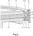
Fig. 4 eine zweite Variante beider Ausführungen des Steuerkolbens des erfindungsgemäßen Steuerventils gemäßFig. 1 undFig. 2 in einer perspektivischen Schnittansicht, und -
Fig. 5 das erfindungsgemäße Steuerventil in einem teilweisen Mittelschnitt.
-
Fig. 1 a first embodiment of a control piston of the control valve according to the invention in a perspective view, -
Fig. 2 A second embodiment of a control piston of the control valve according to the invention in a perspective view, -
Fig. 3 a first variant of both embodiments of the control piston according to the control valve according to the inventionFig. 1 andFig. 2 in a perspective sectional view, -
Fig. 4 a second variant of both embodiments of the control piston according to the control valve according to the inventionFig. 1 andFig. 2 in a perspective sectional view, and -
Fig. 5 the control valve according to the invention in a partial central section.
In
Das in
Der Dichtkolben 11 des oberen Sitzventils 10 ist auf einem zylindrischen Führungsabschnitt 15 des oberen Gehäuseeinsatzes 7 axialbeweglich geführt und von einer als Schraubenfeder ausgebildeten Druckfeder 16, die an dem oberen Gehäuseeinsatz 7 abgestützt ist, nach axial oben in Richtung eines in dem Gehäuseoberteil 5 angeordneten ringstegförmigen äußeren Ventilsitzes 17 belastet. Ein von dem Steuerkolben 9 in dem Zylinder 12 des Gehäuseoberteils 5 eingeschlossener Arbeitsdruckraum 19, an den zum Beispiel eine zu den Radbremszylindern eines Bremskreises führende Bremsleitung angeschlossen sein kann, ist abhängig von der Axialposition des Steuerkolbens 9 mit einem unterhalb des äußeren Ventilsitzes 17 zwischen dem Gehäuseoberteil 5 und dem oberen Gehäuseeinsatz 7 befindlichen ringförmigen Versorgungsdruckraum 20 oder über einen zentralen Entlüftungskanal 18 mit einem in dem Ventilgehäuse 4 unten mittig angeordneten Entlüftungsdruckraum 21 verbindbar oder gegenüber diesen beiden Druckräumen 20, 21 absperrbar. Der Entlüftungskanal 18 ist zentral in und koaxial zu der Mittelachse 53 des Steuerkolbens 22 in demselben ausgebildet.The
Wenn der Steuerkolben 9 mit seinem inneren Ventilsitz 14 an dem Dichtkolben 11 des oberen Sitzventils 10 anliegt und diesen von dem äußeren Ventilsitz 17 weggedrückt hat, ist der Arbeitsdruckraum 19 mit dem mit einer Druckluftquelle beziehungsweise einer Versorgungsdruckleitung in Verbindung stehenden Versorgungsdruckraum 20 verbunden, so dass der Arbeitsdruck in dem Arbeitsdruckraum 19 erhöht wird. Sofern der Steuerkolben 9 mit seinem inneren Ventilsitz 14 von dem Dichtkolben 11 des oberen Sitzventils 10 abgehoben hat, und der Dichtkolben 11 an dem äußeren Ventilsitz 17 anliegt, ist der Arbeitsdruckraum 19 mit dem über einen nicht abgebildeten Schalldämpfer mit der Umgebung in Verbindung stehenden Entlüftungsdruckraum 21 verbunden, so dass der Arbeitsdruck in dem Arbeitsdruckraum 19 verringert wird. Wenn der Steuerkolben 9 mit seinem inneren Ventilsitz 14 an dem Dichtkolben 11 des oberen Sitzventils 10 anliegt, ohne diesen von dem äußeren Ventilsitz 17 abzuheben, ist der Arbeitsdruckraum 19 gegenüber dem Versorgungsdruckraum 20 und dem Entlüftungsdruckraum 21 abgesperrt, so dass der Arbeitsdruck in dem Arbeitsdruckraum 19 konstant gehalten wird.When the
Das in
Die Axialposition des Steuerkolbens 22 ist dadurch einstellbar, dass ein in einem Steuerdruckraum 34 wirksamer Steuerdruck zum Beispiel mittels eines Magnetventils in geeigneter Weise eingestellt wird. Der Steuerdruckraum 34 ist dem Arbeitsdruckraum 32 axial gegenüberliegend von dem Steuerkolben 22 in dem Zylinder 25 des oberen Gehäuseeinsatzes 7 eingeschlossen. Wenn der Steuerkolben 22 mit seinem inneren Ventilsitz 27 an dem Dichtkolben 24 des unteren Sitzventils 23 anliegt und diesen von dem äußeren Ventilsitz 30 weggedrückt hat, ist der Arbeitsdruckraum 32 mit dem mit einer Druckluftquelle in Verbindung stehenden Versorgungsdruckraum 33 verbunden, so dass der Arbeitsdruck in dem Arbeitsdruckraum 32 erhöht wird. Sofern der Steuerkolben 22 mit seinem inneren Ventilsitz 27 von dem Dichtkolben 24 des unteren Sitzventils 23 abgehoben hat, und der Dichtkolben 24 an dem äußeren Ventilsitz 30 anliegt, ist der Arbeitsdruckraum 32 mit dem Entlüftungsdruckraum 21 verbunden, so dass der Arbeitsdruck in dem Arbeitsdruckraum 32 verringert wird. Diese Betriebsstellung ist in
Der Steuerkolben 22 des zweiten Steuerventils 3 weist oben einen zentralen Rohrkörper 35 und darunter einen kreisscheibenförmigen Kolbenkörper 36 auf, die einstückig miteinander verbunden sind. Innerhalb des Rohrkörpers 35 befindet sich der Entlüftungskanal 18 des ersten Steuerventils 2. Der Kolbenkörper 36 trennt den Steuerdruckraum 34 von dem Arbeitsdruckraum 32 und weist zur Abdichtung einen an seinem Außenumfang angeordneten Dichtring 37, 37' auf. Der Dichtring 37, 37' ist als ein Radialdichtring mit einer weitgehend der Dicke des Kolbenkörpers 36 entsprechenden axialen Breite ausgebildet. Der Dichtring 37, 37' weist an seinen beiden axialen Rändern jeweils eine radial schräg nach außen gerichtete erste beziehungsweise zweite Dichtlippe 39, 40 auf, welche an der als Dichtfläche wirksamen Innenwand 38 des Zylinders 25 des oberen Gehäuseeinsatzes 7 anliegen. Zwischen den beiden Dichtlippen 39, 40 ist der Dichtring 37, 37' mit mehreren umfangsseitig verteilt angeordneten Führungskörpern 50 oder mit einem umlaufenden Führungskörper 51 versehen, die in
Wie in den
Der Entlüftungskanal 49 ist als eine ringzylindrische Rohrleitung ausgebildet, die im unteren Teil des Steuerkolbens 22 koaxial um den zentralen Rohrkörper 35 angeordnet und nach oben geschlossen ist, und die nach unten offen in den Entlüftungsdruckraum 21 mündet. Der ringförmige Entlüftungsraum 46, 47 steht über mehrere in dem Kolbenkörper 36 angeordnete radiale Entlüftungsbohrungen 48 mit dem Entlüftungskanal 49 in Verbindung.The
Zwei bevorzugte Ausführungsformen des Dichtrings 37, 37' werden nachfolgend anhand der perspektivischen Ansichten des Steuerkolbens 22 in
Bei der zweiten Ausführungsform gemäß
Zwei mögliche Varianten des Steuerkolbens 22 und des Dichtrings 37, 37', die in Verbindung mit beiden vorbeschriebenen Ausführungen des Dichtrings 37, 37' zur Anwendung kommen können, werden nachfolgend anhand der perspektivischen Schnittansichten des Steuerkolbens 22 mit abgestuften Schnittflächen in
- 11
- Ventileinheitvalve unit
- 22
- Erstes SteuerventilFirst control valve
- 33
- Zweites SteuerventilSecond control valve
- 44
- Ventilgehäusevalve housing
- 55
- Gehäuseoberteil des VentilgehäusesUpper housing part of the valve housing
- 66
- Gehäuseunterteil des VentilgehäusesHousing base of the valve housing
- 77
- Oberer GehäuseeinsatzUpper housing insert
- 88th
- Unterer GehäuseeinsatzLower housing insert
- 99
- Steuerkolbenspool
- 1010
- Oberes SitzventilUpper seat valve
- 1111
- Dichtkolbensealing piston
- 1212
- Zylinder des GehäuseoberteilsCylinder of the housing top
- 1313
- Druckfeder, SchraubenfederCompression spring, coil spring
- 1414
- Innerer VentilsitzInner valve seat
- 1515
- Führungsabschnittguide section
- 1616
- Druckfeder, SchraubenfederCompression spring, coil spring
- 1717
- Äußerer VentilsitzOuter valve seat
- 1818
- Entlüftungskanalvent channel
- 1919
- ArbeitsdruckraumWorking pressure chamber
- 2020
- VersorgungsdruckraumSupply pressure chamber
- 2121
- EntlüftungsdruckraumVenting pressure chamber
- 2222
- Steuerkolbenspool
- 2323
- Unteres SitzventilLower seat valve
- 2424
- Dichtkolbensealing piston
- 2525
- Zylinder des oberen GehäuseeinsatzesCylinder of the upper housing insert
- 2626
- Druckfeder, SchraubenfederCompression spring, coil spring
- 2727
- Innerer VentilsitzInner valve seat
- 2828
- Führungsabschnittguide section
- 2929
- Druckfeder, SchraubenfederCompression spring, coil spring
- 3030
- Äußerer VentilsitzOuter valve seat
- 3131
- Öffnungopening
- 3232
- ArbeitsdruckraumWorking pressure chamber
- 3333
- VersorgungsdruckraumSupply pressure chamber
- 3434
- SteuerdruckraumControl pressure chamber
- 3535
- Rohrkörperpipe body
- 3636
- Kolbenkörperpiston body
- 37, 37'37, 37 '
- Dichtring, RadialdichtringSealing ring, radial seal
- 3838
- Innenwandinner wall
- 3939
- Erste DichtlippeFirst sealing lip
- 4040
- Zweite DichtlippeSecond sealing lip
- 4141
- Führungsabschnittguide section
- 4242
- Befestigungsnut, RingnutMounting groove, ring groove
- 4343
- Befestigungssteg, RingstegFixing web, ring web
- 4444
- Zwischenraumgap
- 4545
- Entlüftungsbohrungvent hole
- 4646
- Entlüftungsraum, RingnutVenting space, annular groove
- 4747
- Entlüftungsraum, RingnutVenting space, annular groove
- 4848
- Entlüftungsbohrungvent hole
- 4949
- Entlüftungskanalvent channel
- 5050
- Führungskörper, FührungsnoppeGuide body, guide knob
- 5151
- Führungskörper, RingstegGuide body, ring bridge
- 5252
- Unterbrechung im RingstegInterruption in the ring land
- 5353
- Mittelachse des SteuerkolbensCenter axis of the control piston
- 5454
- Absatz am GehäuseoberteilParagraph on the upper part of the housing
Claims (11)
Applications Claiming Priority (1)
| Application Number | Priority Date | Filing Date | Title |
|---|---|---|---|
| DE102018108975.9A DE102018108975A1 (en) | 2018-04-16 | 2018-04-16 | Control valve of a compressed air system |
Publications (2)
| Publication Number | Publication Date |
|---|---|
| EP3556620A1 true EP3556620A1 (en) | 2019-10-23 |
| EP3556620B1 EP3556620B1 (en) | 2020-09-16 |
Family
ID=66041220
Family Applications (1)
| Application Number | Title | Priority Date | Filing Date |
|---|---|---|---|
| EP19166192.5A Active EP3556620B1 (en) | 2018-04-16 | 2019-03-29 | Control valve for a compressed air system |
Country Status (3)
| Country | Link |
|---|---|
| US (1) | US10723338B2 (en) |
| EP (1) | EP3556620B1 (en) |
| DE (1) | DE102018108975A1 (en) |
Families Citing this family (6)
| Publication number | Priority date | Publication date | Assignee | Title |
|---|---|---|---|---|
| US10839203B1 (en) * | 2016-12-27 | 2020-11-17 | Amazon Technologies, Inc. | Recognizing and tracking poses using digital imagery captured from multiple fields of view |
| DE102018106975A1 (en) * | 2018-03-23 | 2019-09-26 | Wabco Gmbh | Relay valve of a compressed air system |
| US11468698B1 (en) | 2018-06-28 | 2022-10-11 | Amazon Technologies, Inc. | Associating events with actors using digital imagery and machine learning |
| US11482045B1 (en) | 2018-06-28 | 2022-10-25 | Amazon Technologies, Inc. | Associating events with actors using digital imagery and machine learning |
| US11468681B1 (en) | 2018-06-28 | 2022-10-11 | Amazon Technologies, Inc. | Associating events with actors using digital imagery and machine learning |
| US11443516B1 (en) | 2020-04-06 | 2022-09-13 | Amazon Technologies, Inc. | Locally and globally locating actors by digital cameras and machine learning |
Citations (7)
| Publication number | Priority date | Publication date | Assignee | Title |
|---|---|---|---|---|
| DE2730112A1 (en) * | 1977-07-04 | 1979-01-25 | Festo Maschf Stoll G | Dry lubricated compressor piston - is integral with piston rod and has polyamide or polyurethane seal with sleeve and radially inward walls fitted over piston |
| DE3031012A1 (en) * | 1979-12-29 | 1981-07-02 | VEB Bremshydraulik, DDR 9102 Limbach-Oberfrohna | Vehicle hydraulic brake cylinder - has valve between chamber formed by piston seals and second chamber |
| GB2273541A (en) * | 1992-12-17 | 1994-06-22 | Fichtel & Sachs Ag | A hydraulic friction clutch actuator having a brake fluid and mineral oil resistant seal |
| DE10120321A1 (en) * | 2001-04-26 | 2002-11-14 | Knorr Bremse Systeme | Electropneumatic control valve with a guide arrangement for a control piston |
| DE102008002325A1 (en) * | 2008-06-10 | 2009-12-17 | Zf Friedrichshafen Ag | Sealing element for sealing piston of switching element of automatic gearbox of motor vehicle, has sealing lips attached to sliding surface, where element is directly or indirectly held at piston and made of thermoplastic e.g. PTFE |
| DE102009040759A1 (en) | 2009-09-09 | 2011-03-10 | Wabco Gmbh | Relay valve arrangement |
| DE102014009179A1 (en) | 2014-06-21 | 2015-12-24 | Wabco Gmbh | valve assembly |
Family Cites Families (3)
| Publication number | Priority date | Publication date | Assignee | Title |
|---|---|---|---|---|
| US553738A (en) * | 1896-01-28 | Metallic packing | ||
| DE688624C (en) * | 1937-09-11 | 1940-02-26 | Adolf Winterhoff | Sealing ring for pistons, especially for piston pumps, with a W-shaped profile in cross section |
| NL201093A (en) * | 1956-05-07 |
-
2018
- 2018-04-16 DE DE102018108975.9A patent/DE102018108975A1/en not_active Withdrawn
-
2019
- 2019-03-29 EP EP19166192.5A patent/EP3556620B1/en active Active
- 2019-04-08 US US16/377,819 patent/US10723338B2/en active Active
Patent Citations (8)
| Publication number | Priority date | Publication date | Assignee | Title |
|---|---|---|---|---|
| DE2730112A1 (en) * | 1977-07-04 | 1979-01-25 | Festo Maschf Stoll G | Dry lubricated compressor piston - is integral with piston rod and has polyamide or polyurethane seal with sleeve and radially inward walls fitted over piston |
| DE3031012A1 (en) * | 1979-12-29 | 1981-07-02 | VEB Bremshydraulik, DDR 9102 Limbach-Oberfrohna | Vehicle hydraulic brake cylinder - has valve between chamber formed by piston seals and second chamber |
| GB2273541A (en) * | 1992-12-17 | 1994-06-22 | Fichtel & Sachs Ag | A hydraulic friction clutch actuator having a brake fluid and mineral oil resistant seal |
| DE10120321A1 (en) * | 2001-04-26 | 2002-11-14 | Knorr Bremse Systeme | Electropneumatic control valve with a guide arrangement for a control piston |
| DE10120321B4 (en) | 2001-04-26 | 2004-12-16 | Knorr-Bremse Systeme für Nutzfahrzeuge GmbH | Electropneumatic control valve with a guide arrangement for a control piston |
| DE102008002325A1 (en) * | 2008-06-10 | 2009-12-17 | Zf Friedrichshafen Ag | Sealing element for sealing piston of switching element of automatic gearbox of motor vehicle, has sealing lips attached to sliding surface, where element is directly or indirectly held at piston and made of thermoplastic e.g. PTFE |
| DE102009040759A1 (en) | 2009-09-09 | 2011-03-10 | Wabco Gmbh | Relay valve arrangement |
| DE102014009179A1 (en) | 2014-06-21 | 2015-12-24 | Wabco Gmbh | valve assembly |
Also Published As
| Publication number | Publication date |
|---|---|
| US10723338B2 (en) | 2020-07-28 |
| US20190315329A1 (en) | 2019-10-17 |
| DE102018108975A1 (en) | 2019-10-17 |
| EP3556620B1 (en) | 2020-09-16 |
Similar Documents
| Publication | Publication Date | Title |
|---|---|---|
| EP3556620B1 (en) | Control valve for a compressed air system | |
| DE102004012526B4 (en) | Control valve for controlling the flow of fluid in a hydraulic control unit | |
| EP2952365B1 (en) | Rotary feed-through for a motor vehicle wheel | |
| DE69702807T2 (en) | Multi-purpose valve | |
| EP0197320B1 (en) | Radial piston pump | |
| EP1212517B1 (en) | Camshaft adjuster for internal combustion engines | |
| DE10203886B4 (en) | pilot valve | |
| DE19919015C2 (en) | Hydraulic valve arrangement with locking and floating function | |
| DE112016003470T5 (en) | Master cylinder unit | |
| EP1817216B1 (en) | Electromagnetically actuated valve, in particular in a motor vehicle braking system | |
| EP0223935B1 (en) | Double circuit controlled brake pressure control valve | |
| DE69203374T2 (en) | Hydraulic shock absorber. | |
| DE3443608A1 (en) | DOUBLE BRAKE VALVE ARRANGEMENT | |
| DE10120323C1 (en) | Electropneumatic control valve with a sealing arrangement | |
| DE3837055C2 (en) | ||
| EP3768562A1 (en) | Relay valve for a compressed air system | |
| DE102013002883A1 (en) | Pneumatic change-over valve used for compressed air supply of commercial vehicle, has circumferential groove which is formed in housing and inner portion of main piston through passage opening | |
| EP4114698B1 (en) | Fluid valve, valve arrangement and brake system | |
| WO2019057373A1 (en) | Pump housing of a hydraulic assembly having a pump receiving means | |
| EP1385729A2 (en) | Electropneumatic double control valve comprising a sealing arrangement | |
| DE2926359C2 (en) | Brake pressure regulator | |
| EP1801426B1 (en) | Hydraulic or pneumatic circuit configuration | |
| EP4375092A1 (en) | Tire pressure valve assembly and assembly comprising tire pressure valve assemblies | |
| DE102020209807A1 (en) | Damping valve for a vibration damper | |
| DE69707274T2 (en) | Brake valve assembly for rail vehicles |
Legal Events
| Date | Code | Title | Description |
|---|---|---|---|
| PUAI | Public reference made under article 153(3) epc to a published international application that has entered the european phase |
Free format text: ORIGINAL CODE: 0009012 |
|
| STAA | Information on the status of an ep patent application or granted ep patent |
Free format text: STATUS: THE APPLICATION HAS BEEN PUBLISHED |
|
| AK | Designated contracting states |
Kind code of ref document: A1 Designated state(s): AL AT BE BG CH CY CZ DE DK EE ES FI FR GB GR HR HU IE IS IT LI LT LU LV MC MK MT NL NO PL PT RO RS SE SI SK SM TR |
|
| AX | Request for extension of the european patent |
Extension state: BA ME |
|
| STAA | Information on the status of an ep patent application or granted ep patent |
Free format text: STATUS: REQUEST FOR EXAMINATION WAS MADE |
|
| 17P | Request for examination filed |
Effective date: 20200423 |
|
| RBV | Designated contracting states (corrected) |
Designated state(s): AL AT BE BG CH CY CZ DE DK EE ES FI FR GB GR HR HU IE IS IT LI LT LU LV MC MK MT NL NO PL PT RO RS SE SI SK SM TR |
|
| GRAP | Despatch of communication of intention to grant a patent |
Free format text: ORIGINAL CODE: EPIDOSNIGR1 |
|
| STAA | Information on the status of an ep patent application or granted ep patent |
Free format text: STATUS: GRANT OF PATENT IS INTENDED |
|
| INTG | Intention to grant announced |
Effective date: 20200619 |
|
| GRAS | Grant fee paid |
Free format text: ORIGINAL CODE: EPIDOSNIGR3 |
|
| GRAA | (expected) grant |
Free format text: ORIGINAL CODE: 0009210 |
|
| STAA | Information on the status of an ep patent application or granted ep patent |
Free format text: STATUS: THE PATENT HAS BEEN GRANTED |
|
| AK | Designated contracting states |
Kind code of ref document: B1 Designated state(s): AL AT BE BG CH CY CZ DE DK EE ES FI FR GB GR HR HU IE IS IT LI LT LU LV MC MK MT NL NO PL PT RO RS SE SI SK SM TR |
|
| REG | Reference to a national code |
Ref country code: GB Ref legal event code: FG4D Free format text: NOT ENGLISH |
|
| REG | Reference to a national code |
Ref country code: CH Ref legal event code: EP |
|
| REG | Reference to a national code |
Ref country code: DE Ref legal event code: R096 Ref document number: 502019000215 Country of ref document: DE |
|
| REG | Reference to a national code |
Ref country code: IE Ref legal event code: FG4D Free format text: LANGUAGE OF EP DOCUMENT: GERMAN |
|
| REG | Reference to a national code |
Ref country code: AT Ref legal event code: REF Ref document number: 1313916 Country of ref document: AT Kind code of ref document: T Effective date: 20201015 |
|
| PG25 | Lapsed in a contracting state [announced via postgrant information from national office to epo] |
Ref country code: FI Free format text: LAPSE BECAUSE OF FAILURE TO SUBMIT A TRANSLATION OF THE DESCRIPTION OR TO PAY THE FEE WITHIN THE PRESCRIBED TIME-LIMIT Effective date: 20200916 Ref country code: BG Free format text: LAPSE BECAUSE OF FAILURE TO SUBMIT A TRANSLATION OF THE DESCRIPTION OR TO PAY THE FEE WITHIN THE PRESCRIBED TIME-LIMIT Effective date: 20201216 Ref country code: NO Free format text: LAPSE BECAUSE OF FAILURE TO SUBMIT A TRANSLATION OF THE DESCRIPTION OR TO PAY THE FEE WITHIN THE PRESCRIBED TIME-LIMIT Effective date: 20201216 Ref country code: GR Free format text: LAPSE BECAUSE OF FAILURE TO SUBMIT A TRANSLATION OF THE DESCRIPTION OR TO PAY THE FEE WITHIN THE PRESCRIBED TIME-LIMIT Effective date: 20201217 Ref country code: SE Free format text: LAPSE BECAUSE OF FAILURE TO SUBMIT A TRANSLATION OF THE DESCRIPTION OR TO PAY THE FEE WITHIN THE PRESCRIBED TIME-LIMIT Effective date: 20200916 Ref country code: HR Free format text: LAPSE BECAUSE OF FAILURE TO SUBMIT A TRANSLATION OF THE DESCRIPTION OR TO PAY THE FEE WITHIN THE PRESCRIBED TIME-LIMIT Effective date: 20200916 |
|
| REG | Reference to a national code |
Ref country code: NL Ref legal event code: MP Effective date: 20200916 |
|
| PG25 | Lapsed in a contracting state [announced via postgrant information from national office to epo] |
Ref country code: RS Free format text: LAPSE BECAUSE OF FAILURE TO SUBMIT A TRANSLATION OF THE DESCRIPTION OR TO PAY THE FEE WITHIN THE PRESCRIBED TIME-LIMIT Effective date: 20200916 Ref country code: LV Free format text: LAPSE BECAUSE OF FAILURE TO SUBMIT A TRANSLATION OF THE DESCRIPTION OR TO PAY THE FEE WITHIN THE PRESCRIBED TIME-LIMIT Effective date: 20200916 |
|
| REG | Reference to a national code |
Ref country code: LT Ref legal event code: MG4D |
|
| PG25 | Lapsed in a contracting state [announced via postgrant information from national office to epo] |
Ref country code: SM Free format text: LAPSE BECAUSE OF FAILURE TO SUBMIT A TRANSLATION OF THE DESCRIPTION OR TO PAY THE FEE WITHIN THE PRESCRIBED TIME-LIMIT Effective date: 20200916 Ref country code: LT Free format text: LAPSE BECAUSE OF FAILURE TO SUBMIT A TRANSLATION OF THE DESCRIPTION OR TO PAY THE FEE WITHIN THE PRESCRIBED TIME-LIMIT Effective date: 20200916 Ref country code: EE Free format text: LAPSE BECAUSE OF FAILURE TO SUBMIT A TRANSLATION OF THE DESCRIPTION OR TO PAY THE FEE WITHIN THE PRESCRIBED TIME-LIMIT Effective date: 20200916 Ref country code: RO Free format text: LAPSE BECAUSE OF FAILURE TO SUBMIT A TRANSLATION OF THE DESCRIPTION OR TO PAY THE FEE WITHIN THE PRESCRIBED TIME-LIMIT Effective date: 20200916 Ref country code: PT Free format text: LAPSE BECAUSE OF FAILURE TO SUBMIT A TRANSLATION OF THE DESCRIPTION OR TO PAY THE FEE WITHIN THE PRESCRIBED TIME-LIMIT Effective date: 20210118 Ref country code: CZ Free format text: LAPSE BECAUSE OF FAILURE TO SUBMIT A TRANSLATION OF THE DESCRIPTION OR TO PAY THE FEE WITHIN THE PRESCRIBED TIME-LIMIT Effective date: 20200916 |
|
| RAP4 | Party data changed (patent owner data changed or rights of a patent transferred) |
Owner name: ZF CV SYSTEMS EUROPE BV |
|
| PG25 | Lapsed in a contracting state [announced via postgrant information from national office to epo] |
Ref country code: ES Free format text: LAPSE BECAUSE OF FAILURE TO SUBMIT A TRANSLATION OF THE DESCRIPTION OR TO PAY THE FEE WITHIN THE PRESCRIBED TIME-LIMIT Effective date: 20200916 Ref country code: AL Free format text: LAPSE BECAUSE OF FAILURE TO SUBMIT A TRANSLATION OF THE DESCRIPTION OR TO PAY THE FEE WITHIN THE PRESCRIBED TIME-LIMIT Effective date: 20200916 Ref country code: IS Free format text: LAPSE BECAUSE OF FAILURE TO SUBMIT A TRANSLATION OF THE DESCRIPTION OR TO PAY THE FEE WITHIN THE PRESCRIBED TIME-LIMIT Effective date: 20210116 Ref country code: PL Free format text: LAPSE BECAUSE OF FAILURE TO SUBMIT A TRANSLATION OF THE DESCRIPTION OR TO PAY THE FEE WITHIN THE PRESCRIBED TIME-LIMIT Effective date: 20200916 |
|
| REG | Reference to a national code |
Ref country code: DE Ref legal event code: R097 Ref document number: 502019000215 Country of ref document: DE |
|
| PG25 | Lapsed in a contracting state [announced via postgrant information from national office to epo] |
Ref country code: SK Free format text: LAPSE BECAUSE OF FAILURE TO SUBMIT A TRANSLATION OF THE DESCRIPTION OR TO PAY THE FEE WITHIN THE PRESCRIBED TIME-LIMIT Effective date: 20200916 |
|
| PLBE | No opposition filed within time limit |
Free format text: ORIGINAL CODE: 0009261 |
|
| STAA | Information on the status of an ep patent application or granted ep patent |
Free format text: STATUS: NO OPPOSITION FILED WITHIN TIME LIMIT |
|
| 26N | No opposition filed |
Effective date: 20210617 |
|
| PG25 | Lapsed in a contracting state [announced via postgrant information from national office to epo] |
Ref country code: SI Free format text: LAPSE BECAUSE OF FAILURE TO SUBMIT A TRANSLATION OF THE DESCRIPTION OR TO PAY THE FEE WITHIN THE PRESCRIBED TIME-LIMIT Effective date: 20200916 Ref country code: DK Free format text: LAPSE BECAUSE OF FAILURE TO SUBMIT A TRANSLATION OF THE DESCRIPTION OR TO PAY THE FEE WITHIN THE PRESCRIBED TIME-LIMIT Effective date: 20200916 |
|
| REG | Reference to a national code |
Ref country code: DE Ref legal event code: R081 Ref document number: 502019000215 Country of ref document: DE Owner name: ZF CV SYSTEMS EUROPE BV, BE Free format text: FORMER OWNER: WABCO EUROPE BVBA, BRUESSEL, BE |
|
| PG25 | Lapsed in a contracting state [announced via postgrant information from national office to epo] |
Ref country code: MC Free format text: LAPSE BECAUSE OF FAILURE TO SUBMIT A TRANSLATION OF THE DESCRIPTION OR TO PAY THE FEE WITHIN THE PRESCRIBED TIME-LIMIT Effective date: 20200916 Ref country code: IT Free format text: LAPSE BECAUSE OF FAILURE TO SUBMIT A TRANSLATION OF THE DESCRIPTION OR TO PAY THE FEE WITHIN THE PRESCRIBED TIME-LIMIT Effective date: 20200916 |
|
| REG | Reference to a national code |
Ref country code: BE Ref legal event code: MM Effective date: 20210331 |
|
| PG25 | Lapsed in a contracting state [announced via postgrant information from national office to epo] |
Ref country code: LU Free format text: LAPSE BECAUSE OF NON-PAYMENT OF DUE FEES Effective date: 20210329 Ref country code: IE Free format text: LAPSE BECAUSE OF NON-PAYMENT OF DUE FEES Effective date: 20210329 |
|
| PG25 | Lapsed in a contracting state [announced via postgrant information from national office to epo] |
Ref country code: BE Free format text: LAPSE BECAUSE OF NON-PAYMENT OF DUE FEES Effective date: 20210331 |
|
| REG | Reference to a national code |
Ref country code: CH Ref legal event code: PL |
|
| PG25 | Lapsed in a contracting state [announced via postgrant information from national office to epo] |
Ref country code: LI Free format text: LAPSE BECAUSE OF NON-PAYMENT OF DUE FEES Effective date: 20220331 Ref country code: CH Free format text: LAPSE BECAUSE OF NON-PAYMENT OF DUE FEES Effective date: 20220331 |
|
| PG25 | Lapsed in a contracting state [announced via postgrant information from national office to epo] |
Ref country code: NL Free format text: LAPSE BECAUSE OF NON-PAYMENT OF DUE FEES Effective date: 20200923 Ref country code: CY Free format text: LAPSE BECAUSE OF FAILURE TO SUBMIT A TRANSLATION OF THE DESCRIPTION OR TO PAY THE FEE WITHIN THE PRESCRIBED TIME-LIMIT Effective date: 20200916 |
|
| P01 | Opt-out of the competence of the unified patent court (upc) registered |
Effective date: 20230528 |
|
| PG25 | Lapsed in a contracting state [announced via postgrant information from national office to epo] |
Ref country code: HU Free format text: LAPSE BECAUSE OF FAILURE TO SUBMIT A TRANSLATION OF THE DESCRIPTION OR TO PAY THE FEE WITHIN THE PRESCRIBED TIME-LIMIT; INVALID AB INITIO Effective date: 20190329 |
|
| PG25 | Lapsed in a contracting state [announced via postgrant information from national office to epo] |
Ref country code: MK Free format text: LAPSE BECAUSE OF FAILURE TO SUBMIT A TRANSLATION OF THE DESCRIPTION OR TO PAY THE FEE WITHIN THE PRESCRIBED TIME-LIMIT Effective date: 20200916 |
|
| PGFP | Annual fee paid to national office [announced via postgrant information from national office to epo] |
Ref country code: DE Payment date: 20240130 Year of fee payment: 6 Ref country code: GB Payment date: 20240108 Year of fee payment: 6 |
|
| PGFP | Annual fee paid to national office [announced via postgrant information from national office to epo] |
Ref country code: FR Payment date: 20240213 Year of fee payment: 6 |
|
| PG25 | Lapsed in a contracting state [announced via postgrant information from national office to epo] |
Ref country code: MT Free format text: LAPSE BECAUSE OF FAILURE TO SUBMIT A TRANSLATION OF THE DESCRIPTION OR TO PAY THE FEE WITHIN THE PRESCRIBED TIME-LIMIT Effective date: 20200916 |