EP3556612B1 - Terminal and method for controlling terminal - Google Patents
Terminal and method for controlling terminal Download PDFInfo
- Publication number
- EP3556612B1 EP3556612B1 EP17882294.6A EP17882294A EP3556612B1 EP 3556612 B1 EP3556612 B1 EP 3556612B1 EP 17882294 A EP17882294 A EP 17882294A EP 3556612 B1 EP3556612 B1 EP 3556612B1
- Authority
- EP
- European Patent Office
- Prior art keywords
- vehicle
- image
- control unit
- button
- displayed
- Prior art date
- Legal status (The legal status is an assumption and is not a legal conclusion. Google has not performed a legal analysis and makes no representation as to the accuracy of the status listed.)
- Active
Links
- 238000000034 method Methods 0.000 title claims description 95
- 238000003384 imaging method Methods 0.000 claims description 230
- 230000010365 information processing Effects 0.000 claims description 202
- 230000033001 locomotion Effects 0.000 claims description 130
- 230000004044 response Effects 0.000 claims description 47
- 238000001514 detection method Methods 0.000 claims description 37
- 230000005540 biological transmission Effects 0.000 claims description 31
- 230000008859 change Effects 0.000 claims description 21
- 235000004522 Pentaglottis sempervirens Nutrition 0.000 claims description 8
- 230000008569 process Effects 0.000 description 62
- 239000002131 composite material Substances 0.000 description 55
- 238000010586 diagram Methods 0.000 description 35
- 238000004891 communication Methods 0.000 description 33
- 230000007704 transition Effects 0.000 description 32
- 230000006870 function Effects 0.000 description 14
- 239000000284 extract Substances 0.000 description 10
- 230000001133 acceleration Effects 0.000 description 6
- 239000000470 constituent Substances 0.000 description 4
- 230000000694 effects Effects 0.000 description 4
- 230000008901 benefit Effects 0.000 description 2
- 238000005516 engineering process Methods 0.000 description 2
- 239000010720 hydraulic oil Substances 0.000 description 2
- 239000004973 liquid crystal related substance Substances 0.000 description 2
- 230000007935 neutral effect Effects 0.000 description 2
- 230000001360 synchronised effect Effects 0.000 description 2
- 101100398412 Arabidopsis thaliana ASK1 gene Proteins 0.000 description 1
- 238000005034 decoration Methods 0.000 description 1
- 238000007562 laser obscuration time method Methods 0.000 description 1
- 239000011159 matrix material Substances 0.000 description 1
- 238000012986 modification Methods 0.000 description 1
- 230000004048 modification Effects 0.000 description 1
- 238000000926 separation method Methods 0.000 description 1
Images


Classifications
-
- B—PERFORMING OPERATIONS; TRANSPORTING
- B62—LAND VEHICLES FOR TRAVELLING OTHERWISE THAN ON RAILS
- B62D—MOTOR VEHICLES; TRAILERS
- B62D15/00—Steering not otherwise provided for
- B62D15/02—Steering position indicators ; Steering position determination; Steering aids
- B62D15/027—Parking aids, e.g. instruction means
- B62D15/0285—Parking performed automatically
-
- G—PHYSICS
- G05—CONTROLLING; REGULATING
- G05D—SYSTEMS FOR CONTROLLING OR REGULATING NON-ELECTRIC VARIABLES
- G05D1/00—Control of position, course, altitude or attitude of land, water, air or space vehicles, e.g. using automatic pilots
- G05D1/0011—Control of position, course, altitude or attitude of land, water, air or space vehicles, e.g. using automatic pilots associated with a remote control arrangement
- G05D1/0016—Control of position, course, altitude or attitude of land, water, air or space vehicles, e.g. using automatic pilots associated with a remote control arrangement characterised by the operator's input device
-
- B—PERFORMING OPERATIONS; TRANSPORTING
- B60—VEHICLES IN GENERAL
- B60R—VEHICLES, VEHICLE FITTINGS, OR VEHICLE PARTS, NOT OTHERWISE PROVIDED FOR
- B60R21/00—Arrangements or fittings on vehicles for protecting or preventing injuries to occupants or pedestrians in case of accidents or other traffic risks
-
- B—PERFORMING OPERATIONS; TRANSPORTING
- B60—VEHICLES IN GENERAL
- B60W—CONJOINT CONTROL OF VEHICLE SUB-UNITS OF DIFFERENT TYPE OR DIFFERENT FUNCTION; CONTROL SYSTEMS SPECIALLY ADAPTED FOR HYBRID VEHICLES; ROAD VEHICLE DRIVE CONTROL SYSTEMS FOR PURPOSES NOT RELATED TO THE CONTROL OF A PARTICULAR SUB-UNIT
- B60W30/00—Purposes of road vehicle drive control systems not related to the control of a particular sub-unit, e.g. of systems using conjoint control of vehicle sub-units
- B60W30/06—Automatic manoeuvring for parking
-
- B—PERFORMING OPERATIONS; TRANSPORTING
- B60—VEHICLES IN GENERAL
- B60W—CONJOINT CONTROL OF VEHICLE SUB-UNITS OF DIFFERENT TYPE OR DIFFERENT FUNCTION; CONTROL SYSTEMS SPECIALLY ADAPTED FOR HYBRID VEHICLES; ROAD VEHICLE DRIVE CONTROL SYSTEMS FOR PURPOSES NOT RELATED TO THE CONTROL OF A PARTICULAR SUB-UNIT
- B60W50/00—Details of control systems for road vehicle drive control not related to the control of a particular sub-unit, e.g. process diagnostic or vehicle driver interfaces
- B60W50/08—Interaction between the driver and the control system
- B60W50/10—Interpretation of driver requests or demands
-
- B—PERFORMING OPERATIONS; TRANSPORTING
- B60—VEHICLES IN GENERAL
- B60W—CONJOINT CONTROL OF VEHICLE SUB-UNITS OF DIFFERENT TYPE OR DIFFERENT FUNCTION; CONTROL SYSTEMS SPECIALLY ADAPTED FOR HYBRID VEHICLES; ROAD VEHICLE DRIVE CONTROL SYSTEMS FOR PURPOSES NOT RELATED TO THE CONTROL OF A PARTICULAR SUB-UNIT
- B60W50/00—Details of control systems for road vehicle drive control not related to the control of a particular sub-unit, e.g. process diagnostic or vehicle driver interfaces
- B60W50/08—Interaction between the driver and the control system
- B60W50/14—Means for informing the driver, warning the driver or prompting a driver intervention
-
- B—PERFORMING OPERATIONS; TRANSPORTING
- B62—LAND VEHICLES FOR TRAVELLING OTHERWISE THAN ON RAILS
- B62D—MOTOR VEHICLES; TRAILERS
- B62D1/00—Steering controls, i.e. means for initiating a change of direction of the vehicle
-
- G—PHYSICS
- G05—CONTROLLING; REGULATING
- G05B—CONTROL OR REGULATING SYSTEMS IN GENERAL; FUNCTIONAL ELEMENTS OF SUCH SYSTEMS; MONITORING OR TESTING ARRANGEMENTS FOR SUCH SYSTEMS OR ELEMENTS
- G05B19/00—Programme-control systems
- G05B19/02—Programme-control systems electric
- G05B19/04—Programme control other than numerical control, i.e. in sequence controllers or logic controllers
- G05B19/042—Programme control other than numerical control, i.e. in sequence controllers or logic controllers using digital processors
-
- G—PHYSICS
- G05—CONTROLLING; REGULATING
- G05D—SYSTEMS FOR CONTROLLING OR REGULATING NON-ELECTRIC VARIABLES
- G05D1/00—Control of position, course, altitude or attitude of land, water, air or space vehicles, e.g. using automatic pilots
- G05D1/0011—Control of position, course, altitude or attitude of land, water, air or space vehicles, e.g. using automatic pilots associated with a remote control arrangement
- G05D1/0038—Control of position, course, altitude or attitude of land, water, air or space vehicles, e.g. using automatic pilots associated with a remote control arrangement by providing the operator with simple or augmented images from one or more cameras located onboard the vehicle, e.g. tele-operation
-
- G—PHYSICS
- G06—COMPUTING; CALCULATING OR COUNTING
- G06F—ELECTRIC DIGITAL DATA PROCESSING
- G06F3/00—Input arrangements for transferring data to be processed into a form capable of being handled by the computer; Output arrangements for transferring data from processing unit to output unit, e.g. interface arrangements
- G06F3/01—Input arrangements or combined input and output arrangements for interaction between user and computer
- G06F3/048—Interaction techniques based on graphical user interfaces [GUI]
- G06F3/0481—Interaction techniques based on graphical user interfaces [GUI] based on specific properties of the displayed interaction object or a metaphor-based environment, e.g. interaction with desktop elements like windows or icons, or assisted by a cursor's changing behaviour or appearance
- G06F3/04817—Interaction techniques based on graphical user interfaces [GUI] based on specific properties of the displayed interaction object or a metaphor-based environment, e.g. interaction with desktop elements like windows or icons, or assisted by a cursor's changing behaviour or appearance using icons
-
- G—PHYSICS
- G06—COMPUTING; CALCULATING OR COUNTING
- G06F—ELECTRIC DIGITAL DATA PROCESSING
- G06F3/00—Input arrangements for transferring data to be processed into a form capable of being handled by the computer; Output arrangements for transferring data from processing unit to output unit, e.g. interface arrangements
- G06F3/01—Input arrangements or combined input and output arrangements for interaction between user and computer
- G06F3/048—Interaction techniques based on graphical user interfaces [GUI]
- G06F3/0484—Interaction techniques based on graphical user interfaces [GUI] for the control of specific functions or operations, e.g. selecting or manipulating an object, an image or a displayed text element, setting a parameter value or selecting a range
- G06F3/04842—Selection of displayed objects or displayed text elements
-
- G—PHYSICS
- G06—COMPUTING; CALCULATING OR COUNTING
- G06F—ELECTRIC DIGITAL DATA PROCESSING
- G06F3/00—Input arrangements for transferring data to be processed into a form capable of being handled by the computer; Output arrangements for transferring data from processing unit to output unit, e.g. interface arrangements
- G06F3/01—Input arrangements or combined input and output arrangements for interaction between user and computer
- G06F3/048—Interaction techniques based on graphical user interfaces [GUI]
- G06F3/0484—Interaction techniques based on graphical user interfaces [GUI] for the control of specific functions or operations, e.g. selecting or manipulating an object, an image or a displayed text element, setting a parameter value or selecting a range
- G06F3/04847—Interaction techniques to control parameter settings, e.g. interaction with sliders or dials
-
- G—PHYSICS
- G06—COMPUTING; CALCULATING OR COUNTING
- G06F—ELECTRIC DIGITAL DATA PROCESSING
- G06F3/00—Input arrangements for transferring data to be processed into a form capable of being handled by the computer; Output arrangements for transferring data from processing unit to output unit, e.g. interface arrangements
- G06F3/01—Input arrangements or combined input and output arrangements for interaction between user and computer
- G06F3/048—Interaction techniques based on graphical user interfaces [GUI]
- G06F3/0484—Interaction techniques based on graphical user interfaces [GUI] for the control of specific functions or operations, e.g. selecting or manipulating an object, an image or a displayed text element, setting a parameter value or selecting a range
- G06F3/0486—Drag-and-drop
-
- G—PHYSICS
- G06—COMPUTING; CALCULATING OR COUNTING
- G06F—ELECTRIC DIGITAL DATA PROCESSING
- G06F3/00—Input arrangements for transferring data to be processed into a form capable of being handled by the computer; Output arrangements for transferring data from processing unit to output unit, e.g. interface arrangements
- G06F3/01—Input arrangements or combined input and output arrangements for interaction between user and computer
- G06F3/048—Interaction techniques based on graphical user interfaces [GUI]
- G06F3/0487—Interaction techniques based on graphical user interfaces [GUI] using specific features provided by the input device, e.g. functions controlled by the rotation of a mouse with dual sensing arrangements, or of the nature of the input device, e.g. tap gestures based on pressure sensed by a digitiser
- G06F3/0488—Interaction techniques based on graphical user interfaces [GUI] using specific features provided by the input device, e.g. functions controlled by the rotation of a mouse with dual sensing arrangements, or of the nature of the input device, e.g. tap gestures based on pressure sensed by a digitiser using a touch-screen or digitiser, e.g. input of commands through traced gestures
- G06F3/04883—Interaction techniques based on graphical user interfaces [GUI] using specific features provided by the input device, e.g. functions controlled by the rotation of a mouse with dual sensing arrangements, or of the nature of the input device, e.g. tap gestures based on pressure sensed by a digitiser using a touch-screen or digitiser, e.g. input of commands through traced gestures for inputting data by handwriting, e.g. gesture or text
-
- H—ELECTRICITY
- H04—ELECTRIC COMMUNICATION TECHNIQUE
- H04N—PICTORIAL COMMUNICATION, e.g. TELEVISION
- H04N7/00—Television systems
- H04N7/18—Closed-circuit television [CCTV] systems, i.e. systems in which the video signal is not broadcast
-
- G—PHYSICS
- G05—CONTROLLING; REGULATING
- G05B—CONTROL OR REGULATING SYSTEMS IN GENERAL; FUNCTIONAL ELEMENTS OF SUCH SYSTEMS; MONITORING OR TESTING ARRANGEMENTS FOR SUCH SYSTEMS OR ELEMENTS
- G05B2219/00—Program-control systems
- G05B2219/20—Pc systems
- G05B2219/23—Pc programming
- G05B2219/23044—Transparent overlay with touch sensors, put over display panel, select function
-
- G—PHYSICS
- G05—CONTROLLING; REGULATING
- G05B—CONTROL OR REGULATING SYSTEMS IN GENERAL; FUNCTIONAL ELEMENTS OF SUCH SYSTEMS; MONITORING OR TESTING ARRANGEMENTS FOR SUCH SYSTEMS OR ELEMENTS
- G05B2219/00—Program-control systems
- G05B2219/20—Pc systems
- G05B2219/26—Pc applications
- G05B2219/2637—Vehicle, car, auto, wheelchair
-
- G—PHYSICS
- G06—COMPUTING; CALCULATING OR COUNTING
- G06F—ELECTRIC DIGITAL DATA PROCESSING
- G06F21/00—Security arrangements for protecting computers, components thereof, programs or data against unauthorised activity
- G06F21/30—Authentication, i.e. establishing the identity or authorisation of security principals
- G06F21/31—User authentication
- G06F21/36—User authentication by graphic or iconic representation
-
- G—PHYSICS
- G06—COMPUTING; CALCULATING OR COUNTING
- G06F—ELECTRIC DIGITAL DATA PROCESSING
- G06F2203/00—Indexing scheme relating to G06F3/00 - G06F3/048
- G06F2203/048—Indexing scheme relating to G06F3/048
- G06F2203/04803—Split screen, i.e. subdividing the display area or the window area into separate subareas
-
- G—PHYSICS
- G06—COMPUTING; CALCULATING OR COUNTING
- G06F—ELECTRIC DIGITAL DATA PROCESSING
- G06F3/00—Input arrangements for transferring data to be processed into a form capable of being handled by the computer; Output arrangements for transferring data from processing unit to output unit, e.g. interface arrangements
- G06F3/01—Input arrangements or combined input and output arrangements for interaction between user and computer
- G06F3/017—Gesture based interaction, e.g. based on a set of recognized hand gestures
-
- G—PHYSICS
- G06—COMPUTING; CALCULATING OR COUNTING
- G06F—ELECTRIC DIGITAL DATA PROCESSING
- G06F3/00—Input arrangements for transferring data to be processed into a form capable of being handled by the computer; Output arrangements for transferring data from processing unit to output unit, e.g. interface arrangements
- G06F3/01—Input arrangements or combined input and output arrangements for interaction between user and computer
- G06F3/048—Interaction techniques based on graphical user interfaces [GUI]
- G06F3/0484—Interaction techniques based on graphical user interfaces [GUI] for the control of specific functions or operations, e.g. selecting or manipulating an object, an image or a displayed text element, setting a parameter value or selecting a range
Definitions
- the present invention relates to a terminal and a method for controlling the terminal.
- terminals equipped with a touch panel such as smartphones and tablet terminals have been prevalent.
- GB 2534471 A shows a terminal and method according to the preamble of claims 1 and 7.
- the present invention has been made in view of the above-described circumstance and it is an object thereof to ensure that a user can perform operation accurately when the user operates a touch panel of a terminal to control propulsion of a vehicle.
- the present invention provides a terminal according to claim 1.
- the terminal includes a touch panel that displays an image and accepts a touch operation; and a terminal control unit that causes the touch panel to display a vehicle control screen on which an operation button allowing the touch operation is displayed, moves a position of the operation button following a movement of the position of the touch operation, and maintains a state where the touch operation is performed on the operation button when the position of the touch operation moves after the touch operation is performed on the operation button displayed on the vehicle control screen; and transmits a propulsion instruction signal instructing propulsion of the vehicle to an information processing device provided in a vehicle while the touch operation is being performed on the operation button displayed on the vehicle control screen, and stops transmission of the propulsion instruction signal in response to ending of the touch operation on the operation button.
- the terminal control unit displays the operation button continuously at a position of the operation button at the time when the touch operation is ended when the touch operation on the operation button displayed on the vehicle control screen is ended.
- the terminal control unit displays the operation button at a predetermined position on the vehicle control screen when the touch operation on the operation button displayed on the vehicle control screen is ended.
- the terminal control unit causes the touch panel to display a lock screen on which a slide bar and a slide button are displayed, the slide button being positioned at one end of the slide bar, moving along the slide bar in accordance with a swipe operation, and moving to the one end of the slide bar in response to ending of the swipe operation, and changes a screen to be displayed on the touch panel from the lock screen to the vehicle control screen when the slide button is positioned at another end of the slide bar by the swipe operation for a predetermined period of time and changes the slide button positioned at the other end of the slide bar to the operation button so as to cause the slide button to function as the operation button.
- the terminal control unit changes an image indicative of the operation button between when the operation button is being operated and when the operation button is not operated.
- yet another aspect of the present invention further includes a housing and a housing state detection unit that detects a state of the housing, wherein the terminal control unit acquires imaging data that is based on a result of imaging of a camera provided in the vehicle while the vehicle control screen is being displayed, causes the touch panel to display the acquired image based on the imaging data, and displays the operation button in a superposed manner on the image based on the imaging data; and changes an image to be displayed on the touch panel in accordance with a state of the housing detected by the housing state detection unit and maintains display of the operation button even when an image to be displayed on the touch panel is changed.
- the terminal control unit causes the touch panel to display an overhead image which is an image of a bird's eye view of the vehicle as the image based on the imaging data when it is detected by the housing state detection unit that an orientation of the housing is placed in a first orientation, and causes the touch panel to display an outside-of-vehicle image which is an image of an outside of the vehicle imaged by the camera as the image based on the imaging data when it is detected by the housing state detection unit that the orientation of the housing is placed in a second orientation that is different than the first orientation.
- yet another aspect of the present invention provides a method of controlling a terminal according to claim 7.
- the terminal includes a touch panel that displays an image and accepts a touch operation.
- the method includes displaying, on the touch panel, a vehicle control screen on which an operation button allowing the touch operation is displayed and moving a position of the operation button following a movement of the position of the touch operation, and maintaining a state where the touch operation is performed on the operation button when the position of the touch operation moves after the touch operation is performed on the operation button displayed on the vehicle control screen; and transmitting a propulsion instruction signal instructing propulsion of the vehicle to an information processing device provided in the vehicle while the touch operation is being performed on the operation button displayed on the vehicle control screen and stopping transmission of the propulsion instruction signal in response to ending of the touch operation on the operation button.
- a user can perform the operation accurately when the user operates a touch panel of a terminal to control propulsion of a vehicle.
- Figure 1 is a diagram that illustrates an outline of an information processing system 1 according to this embodiment.
- the information processing system 1 includes a vehicle system 2 provided in a vehicle S and a mobile terminal 3 possessed by a user.
- the vehicle system 2 includes an information processing device 4 and a vehicle drive control device 5.
- the information processing device 4 and the vehicle drive control device 5 are capable of performing communication via a bus 6.
- the mobile terminal 3 is a tablet mobile phone (so-called smartphone) carried by a user.
- the information processing device 4 of the vehicle system 2 and the mobile terminal 3 are capable of performing communication by wireless communication.
- the mobile terminal 3 includes a housing 8.
- the housing 8 is a plate-like member having a rectangular front face 8a, and a touch panel 9 (display panel) is provided in a wide area of the front face 8a.
- a rectangular shape does not mean a perfect rectangular shape but also includes, for example, a substantially rectangular shape four apexes of which are rounded.
- the mobile terminal 3 is not limited to a smartphone but may be a tablet computer or the like.
- the user is a person having authority to control the vehicle S such as an owner of the vehicle S, etc.
- the vehicle S is an automatically operated four-wheeled vehicle.
- the vehicle S according to this embodiment has the following functions associated with operating an engine switch to turn on/off an engine and locking/unlocking of a door.
- the vehicle S has the functions of operating the engine switch to turn on/off the engine and locking/unlocking the door by an operation performed on a dedicated remote controller. Since existing technology is used in these functions, detailed explanation of these functions is not provided.
- the user can operate the engine switch to turn on/off the engine and lock/unlock the door of the vehicle S by operating the dedicated remote controller outside the vehicle.
- the information processing system 1 is a system that enables what will be described hereinbelow. Specifically, the information processing system 1 makes it possible for the user to move the vehicle S, which is stopped, to another position and park it there by operating the mobile terminal 3 without driving the vehicle S. For example, when the vehicle S should be parked in a parking position in a parking space, a garage, etc., the information processing system 1 makes it possible for the user to move, to the parking position, the vehicle S which is stopped at a before-parking position near the parking position and park it there by operating the mobile terminal 3 without driving the vehicle S
- the information processing system 1 makes it possible for the user to move the vehicle S, which is stopped in the parking position, to an after-exit stop position near the parking position and stop it there by operating the mobile terminal 3 without driving the vehicle S. Accordingly, the user can perform parking and exiting of the vehicle S by using the information processing system 1 in a state where the user is not on board the vehicle S.
- the user can park the vehicle S at the parking position in the following manner in a state where it is difficult to open and close the door of the vehicle S because the vehicle S and the other vehicle adjacent to it are close to each other.
- the user can get off the vehicle S before parking the vehicle S in the parking position and stop the vehicle S in the parking position by using the information processing system 1. By virtue of this, there is no need to open and close the door of the vehicle S after the vehicle S is stopped in the parking position, and the user can stop the vehicle S smoothly.
- the user can make the vehicle S exit smoothly without getting on the vehicle S using the information processing system 1 and then get on the vehicle S.
- FIG. 2 is a block diagram that illustrates the functional configuration of the mobile terminal 3.
- the mobile terminal 3 includes a terminal control unit 20, a terminal communication unit 21, a touch panel 9, a terminal storage unit 22, and a housing state detection unit 23.
- the terminal control unit 20 includes a CPU, ROM, RAM, an ASIC, a signal processing circuit, etc., and controls individual units of the mobile terminal 3.
- the CPU reads a program stored in the ROM onto the RAM to perform processing; for example, performs processing by a function implemented in the ASIC; and performs processing by cooperation of hardware and software, for example, by performing the processing by performing signal processing by the signal processing circuit.
- the terminal communication unit 21 wirelessly communicates with an external device (including the information processing device 4) according to the Wi-Fi (registered trademark) standards under the control of the terminal control unit 20.
- the communication protocol used for the wireless communication performed between the mobile terminal 3 and the information processing device 4 is Wi-Fi, but the communication protocol used for wireless communication performed between these devices may be any protocol other than Wi-Fi.
- the communication protocol may be Bluetooth (registered trademark).
- the touch panel 9 includes a display panel such as a liquid crystal panel and an organic EL panel and displays an image on the display panel under the control of the terminal control unit 20. Also, the touch panel 9 includes a touch sensor disposed to overlap the display panel, and the touch sensor detects an operation by a user on the touch panel 9 and outputs a signal corresponding to the operation that has been detected to the terminal control unit 20. The terminal control unit 20 performs processing that corresponds to the operation on the touch panel 9 by the user on the basis of the input from the touch panel 9.
- the terminal storage unit 22 includes a non-volatile memory such as EEPROM and rewritably stores in a non-volatile manner various pieces of data.
- EEPROM electrically erasable programmable read-only memory
- the terminal storage unit 22 stores a dedicated application AP.
- the dedicated application AP is an application used when a user performs automatic vehicle movement using the information processing system 1 as will be described later.
- the dedicated application AP is, for example, an application that a company that manufactures and sells the information processing device 4 provides.
- a user uses a predetermined application download system and, in advance, downloads the dedicated application AP to the mobile terminal 3.
- the housing state detection unit 23 includes an acceleration sensor, a gyro sensor, and a tilt sensor provided in the housing 8 and, on the basis of detected values of these sensors, detects a state of the housing 8.
- the housing state detection unit 23 outputs information indicative of the state of the housing 8 that has been detected to the terminal control unit 20.
- the sensor used when the housing state detection unit 23 detects the state of the housing 8 is not limited to the acceleration sensor, the gyro sensor, or the tilt sensor. Also, a method when the housing state detection unit 23 detects the state of the housing 8 may be any method.
- the housing state detection unit 23 detects, as the state of the housing 8, at least, (1) the fact that the orientation of the housing 8 has been placed in the "portrait orientation;” (2) the fact that the orientation of the housing 8 has been placed in the "landscape orientation;” (3) the fact that the housing 8 has made the “rightward motion” when the orientation of the housing 8 is in the “landscape orientation;” and (4) the fact that the housing 8 has made the "leftward motion” when the orientation of the housing is in the "landscape orientation.”
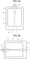
- Figure 3A is a diagram used in an explanation of the "portrait orientation.”
- the housing 8 is a plate-like member having a rectangular front face 8a.
- the shape of the touch panel 9 is rectangular with a long side along a long side T1 of the housing 8 and a short side along a short side T2 of the housing 8.
- an outer periphery of the front face 8a is defined by the long side T1 and the short side T2.
- a virtual line that extends along the long side T1 of the housing 8 is expressed as a "virtual long-side straight line” with a reference sign "KA” assigned thereto.
- a virtual line extending in the vertical direction is expressed as a “virtual vertical straight line” with a reference sign "EN” assigned thereto.
- a virtual line that is orthogonal to the virtual vertical straight line EN is expressed as a "virtual orthogonal straight line” with a reference sign "TN” assigned thereto.
- the "portrait orientation” is a state where the angle of the virtual long-side straight line KA with reference to the virtual vertical straight line EN in a three-dimensional space falls within the range of angle ⁇ 1.
- the value of the angle ⁇ 1 is defined as appropriate on the basis of the viewpoint of the margin when the user intentionally places the orientation of the mobile terminal 3 in the "portrait orientation.”
- a state is entered where the direction of the long side T1 of the housing 8 is in the vertical direction, and a state is entered where the direction of the long side of the touch panel 9 is in the vertical direction.
- the "portrait orientation” corresponds to a "first orientation.”
- Figure 3B is a diagram used in an explanation of the "landscape orientation.”
- the "landscape orientation" is a state where the angle of the virtual long-side straight line KA with reference to the virtual orthogonal straight line TN in the three-dimensional space falls within the range of angle ⁇ 2.
- the angle ⁇ 2 is defined as appropriate on the basis of the viewpoint of the margin when the user intentionally places the orientation of the mobile terminal 3 in the "landscape orientation.”
- a state is entered where the direction of the long side T1 of the housing 8 is in the direction orthogonal to the vertical direction and a state is entered where the direction of the long side of the touch panel 9 is in the direction orthogonal to the vertical direction.
- the "landscape orientation" corresponds to a "second orientation.”
- Figure 4A is a diagram used in an explanation of the "rightward motion.”
- the "rightward motion” is a motion by which the housing 8 moves in the rightward direction when the housing 8 is viewed in its plan view, by a distance exceeding a distance K1 (for example, three centimeters), and within a time frame GG1 (for example, 0.5 seconds) in the state where the orientation of the housing 8 is in the "landscape orientation.”
- the rightward direction does not need to fully conform to the direction orthogonal to the vertical direction, and a certain margin is taken into account.
- the distance K1 and the time frame GG1 are defined as appropriate on the basis of the viewpoint that they are used as the thresholds for determining the fact that the user intentionally causes the housing 8 to make the "rightward motion.”
- the "rightward motion” corresponds to "a first motion in which the state of the housing 8 changes in a first mode.”
- Figure 4B is a diagram used in an explanation of the "leftward motion.”
- the "leftward motion” is a motion by which the housing 8 moves in the leftward direction when the housing 8 is viewed in its plan view, by a distance exceeding a distance K2 (for example, 3 centimeters), and within a time frame GG2 (for example, 0.5 seconds) in the state where the orientation of the housing 8 is in the "landscape orientation.”
- the leftward direction does not need to fully conform to the direction orthogonal to the vertical direction, and a certain margin is taken into account.
- the distance K2 and the time frame GG2 are defined as appropriate on the basis of the viewpoint that they are used as the thresholds for determining the fact that the user intentionally causes the housing 8 to make the "leftward motion.”
- the "leftward motion” corresponds to "a second motion in which the state of the housing 8 changes in a second mode.”
- Figure 5 is a block diagram that illustrates a functional configuration of the information processing device 4.
- the information processing device 4 includes an information processing device control unit 30, an information processing device communication unit 31, a display device 32, an information processing device storage unit 33, an operation input unit 34, a GPS unit 35, a relative azimuth detection unit 36, a bus interface 37, and a camera interface 38.
- the information processing device control unit 30 includes a CPU, ROM, RAM, an ASIC, a signal processing circuit, etc., and controls individual units of the information processing device 4.
- the CPU reads a program stored in the ROM onto the RAM to perform processing; for example, performs processing by a function implemented in the ASIC; and performs processing by cooperation of hardware and software, for example, by performing processing by performing signal processing by the signal processing circuit.
- the information processing device communication unit 31 wirelessly communicates with an external device (including the mobile terminal 3) according to the Wi-Fi standards under the control of the information processing device control unit 30.
- the display device 32 includes a display panel such as a liquid crystal panel and an organic EL panel, and displays an image on the display panel under the control of the information processing device control unit 30.
- the information processing device storage unit 33 includes a non-volatile memory such as EEPROM and a hard disk, and stores various pieces of data rewritably in a non-volatile manner.
- the information processing device storage unit 33 stores map data 33a.
- the map data 33a stores information used in displaying a map on the display device 32 and information used in searching for a route (information on so-called link, information on so-called node, etc.). Also, the map data 33a stores, in relation to facilities in which the vehicle S can be parked such as a parking space, a detailed map of the inside of the facilities and information indicative of the structure of the facilities (hereinafter referred to as "parking map information").
- the operation input unit 34 includes an operator such as a switch provided on the information processing device 4, detects an operation by the user on the operator, and outputs a signal corresponding to the operation that has been detected to the information processing device control unit 30.
- the information processing device control unit 30 performs, on the basis of the input from the operation input unit 34, processing corresponding to the operation by the user on the operator.
- the GPS unit 35 receives a GPS radio wave from a GPS satellite via a not-shown GPS antenna and computes, from a GPS signal superimposed on the GPS radio waves, a current position of the vehicle S and a direction of travel of the vehicle S.
- the GPS unit 35 outputs information indicative of the current position of the vehicle S that has been computed and the information indicative of the direction of travel of the vehicle S that has been computed to the information processing device control unit 30.
- the relative azimuth detection unit 36 includes a gyro sensor and an acceleration sensor.
- the gyro sensor is configured, for example, by a vibration gyroscope and detects a relative azimuth of the vehicle S (for example, the turning amount in the yaw axis direction).
- the acceleration sensor detects an acceleration acting upon the vehicle S (for example, an inclination of the vehicle with respect to the direction of travel).
- the relative azimuth detection unit 36 outputs the information indicative of the relative azimuth of the vehicle S that has been detected and the information indicative of the acceleration acting on the vehicle S that has been detected to the information processing device control unit 30.
- the bus interface 37 includes a communication interface corresponding to the bus 6 and, under the control of the information processing device control unit 30, communicates with an external device (including vehicle drive control device 5) connected to the bus 6.
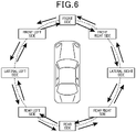
- the camera interface 38 communicates with a camera provided in the vehicle S under the control of the information processing device control unit 30.
- a front imaging camera CA1 a front right-side imaging camera CA2, a lateral right-side imaging camera CA3, a rear right-side imaging camera CA4, a rear imaging camera CA5, a rear left-side imaging camera CA6, a lateral left-side imaging camera CA7, and a front left-side imaging camera CA8.
- a front imaging camera CA1 a front right-side imaging camera CA2, a lateral right-side imaging camera CA3, a rear right-side imaging camera CA4, a rear imaging camera CA5, a rear left-side imaging camera CA6, a lateral left-side imaging camera CA7, and a front left-side imaging camera CA8.
- Figure 6 is a diagram used in an explanation of the direction in which the outside-of-vehicle imaging camera performs imaging. Note that Figure 6 will also be used in an explanation of the switching of the outside-of-vehicle image G2 which will be described later.
- the front imaging camera CA1 is a camera that images the front side of the vehicle S (see Figure 6 ).
- the front right-side imaging camera CA2 is a camera that images the front right side of the vehicle S (see Figure 6 ).
- the lateral right-side imaging camera CA3 is a camera that images the lateral right side of the vehicle S (see Figure 6 ).
- the rear right-side imaging camera CA4 is a camera that images the rear right side of the vehicle S (see Figure 6 ).
- the rear imaging camera CA5 is a camera that images the rear side of the vehicle S (see Figure 6 ).
- the rear left-side imaging camera CA6 is a camera that images the rear left side of the vehicle S (see Figure 6 ).
- the lateral left-side imaging camera CA7 is a camera that images the lateral left side of the vehicle S (see Figure 6 ).
- the front left-side imaging camera CA8 is a camera that images the front left side of the vehicle S (see Figure 6 ).
- Each of the outside-of-vehicle imaging cameras performs imaging at a predetermined cycle, generates captured image data on the basis of a result of the imaging, and outputs the captured image data that has been generated to the information processing device control unit 30 via the camera interface 38.
- the modes of the outside-of-vehicle imaging cameras provided in the vehicle S are not limited to the modes according to this embodiment.
- a configuration is possible in which the outside-of-vehicle imaging cameras are provided in the vehicle S in the following manner.
- the outside-of-vehicle imaging cameras four cameras, i.e., the front imaging camera CA1, the lateral right-side imaging camera CA3, the rear imaging camera CA5, and the lateral left-side imaging camera CA7 are provided; the lateral right side and the front right side of the vehicle S are imaged by the lateral right-side imaging camera CA3; the rear side, the rear right side, and the rear left side of the vehicle S are imaged by the rear imaging camera CA5; and the lateral left side and the front left side of the vehicle S are imaged by the lateral left-side imaging camera.
- the front imaging camera CA1 the lateral right-side imaging camera CA3, the rear imaging camera CA5, and the lateral left-side imaging camera CA7 are provided
- the lateral right side and the front right side of the vehicle S are imaged by the lateral right-side imaging camera CA3
- the rear side, the rear right side, and the rear left side of the vehicle S are imaged by the rear imaging camera CA5
- the front imaging camera CA1, the lateral right-side imaging camera CA3, the rear imaging camera CA5, and the lateral left-side imaging camera CA7 are used as cameras for use in generation of overhead image data (which will be described later).
- the cameras for use in generation of the overhead image data are not distinguished from each other, they are referred to as an "overhead camera.”
- Each of the overhead cameras are a wide angle camera and provided at an appropriate position in the vehicle S in terms of use in the generation of the overhead image data.
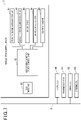
- Figure 7 is a block diagram that illustrates a functional configuration of the vehicle drive control device 5.
- the vehicle drive control device 5 includes a vehicle drive control device control unit 50, a road-to-vehicle communication unit 51, a vehicle-to-vehicle communication unit 52, a radar device 53, a vehicle speed sensor 54, a yaw rate sensor 55, and a bus interface 56.
- the vehicle drive control device control unit 50 includes a CPU, ROM, RAM, an ASIC, a signal processing circuit, etc., and controls individual units of the vehicle drive control device 5.
- the CPU reads a program stored in the ROM onto the RAM to perform processing; for example, performs processing by a function implemented in the ASIC; and performs processing by cooperation of hardware and software, for example, by performing the processing by performing signal processing by the signal processing circuit.
- the road-to-vehicle communication unit 51 receives, from a roadside machine installed on a road, etc., a light beacon, a radio beacon, and information transmitted by narrow-band wireless communication such as dedicated short range communications (DSRC).
- the information transmitted from the roadside machine to the road-to-vehicle communication unit 51 includes, for example, information on another vehicle, information on a pedestrian, etc.
- the road-to-vehicle communication unit 51 outputs the information that has been received from the roadside machine to the vehicle drive control device control unit 50.
- the vehicle-to-vehicle communication unit 52 transmits and receives information with another vehicle residing around the vehicle S by wireless communication with each other.
- the information transmitted and received by the vehicle-to-vehicle communication unit 52 includes, for example, identification information for identifying the vehicle S and the other vehicle, information indicative of the positions of the vehicle S and the other vehicle, the information indicative of the speeds of the vehicle S and the other vehicle, information indicative of the direction of travel of the vehicle S and the direction of travel of the other vehicle, information indicative of points in time at which the vehicle S and the other vehicle stop, and the like.
- the vehicle-to-vehicle communication unit 52 outputs the received information to the vehicle drive control device control unit 50.
- the radar device 53 emits, for example, a radio wave of a millimeter wave radar, a laser radar, etc., a sound wave of a ultrasonic radar, etc., and the like to the outside of the vehicle.
- the radar device 53 detects objects existing around the vehicle S by receiving a reflected wave that is reflected from the objects existing around the vehicle S (for example, another vehicle and a person).
- the radar device 53 outputs the information on the objects that have been detected to the vehicle drive control device control unit 50.
- the vehicle speed sensor 54 detects a speed of the vehicle S (hereinafter referred to as “vehicle speed”) and outputs the information on the vehicle speed that has been detected to the vehicle drive control device control unit 50.
- the yaw rate sensor 55 detects a yaw rate acting upon the vehicle S and outputs the information on the yaw rate that has been detected to the vehicle drive control device control unit 50.
- the bus interface 56 includes a communication interface corresponding to the bus 6 and communicates with an external device (including the information processing device 4) connected to the bus 6 under the control of the vehicle drive control device control unit 50.
- an engine ECU 60 As illustrated in Figure 7 , to the bus 6, as ECUs, an engine ECU 60, a transmission ECU 61, a brake ECU 62, and a steering ECU 63 are connected.
- the vehicle drive control device control unit 50 of the vehicle drive control device 5 outputs a control signal to the individual ECUs via the bus 6 and controls the individual ECUs.
- the engine ECU 60 controls a throttle actuator that opens and closes an electronic throttle valve provided in an intake pipe of the engine and adjusts the number of revolutions of the engine on the basis of the control signal input from the vehicle drive control device control unit 50.
- the transmission ECU 61 controls, on the basis of the control signal input from the vehicle drive control device control unit 50, a hydraulic control device that adjusts the hydraulic pressure of hydraulic oil supplied to the transmission, thereby adjusts the hydraulic pressure of the hydraulic oil supplied to the transmission, changes the gear ratio of the transmission, and changes the rotation speed and torque transmitted from the engine.
- the transmission ECU 61 changes the state of the gear of the vehicle S among Parking (P), Reverse (R), Drive (D), Neutral (N), and Low (L) on the basis of the control signal input from the vehicle drive control device control unit 50.
- the brake ECU 62 controls a brake device provided on a wheel of the vehicle S and performs braking of the vehicle S on the basis of the control signal input from the vehicle drive control device control unit 50.
- the steering ECU 63 controls a steering device provided in the vehicle S and performs steering of the vehicle S on the basis of the control signal input from the vehicle drive control device control unit 50.
- the vehicle drive control device 5 is capable of causing the vehicle S to automatically move from the stop position in which the vehicle S is stopped to the target position that is an objective position to which the vehicle S having moved from the stop position should be stopped and stop there on the basis of automatic driving route information and without involving driving of the vehicle S by the user.
- the information processing device 4 outputs the automatic driving route information to the vehicle drive control device 5 in the automatic vehicle movement.
- Figure 8 is a diagram used in an explanation of automatic driving route information.
- the automatic driving route information includes path information indicative of a path of the vehicle S from the stop position to the target position in a virtual coordinate system where the origin is defined by the vehicle S stopping at the stop position, the y-axis is defined by the front-rear direction of the vehicle S, and the x-axis is defined by the right-left direction of the vehicle S.
- the path information includes pieces of information indicative of the respective coordinates of the points representing the path of the vehicle S in the virtual coordinate system and pieces of information indicative of directions of the vehicle S at the respective points in the virtual coordinate system.
- Figure 8 illustrates a virtual coordinate system KZ1 which is an example of the virtual coordinate system and an example of the path of the vehicle S in the virtual coordinate system KZ1, which are illustrated in a simplified manner so that they are suitable for explanations.
- the path information includes pieces of information indicative of the coordinates of a point P0 (which is the origin and corresponds to the stop position), a point P1, a point P2, a point P3, a point P4, and a point P5 (which is a point that corresponds to the target position) and pieces of information indicative of the directions of the vehicle S in the virtual coordinate system KZ1 at the respective points.
- the vehicle drive control device control unit 50 of the vehicle drive control device 5 outputs control signals to the engine ECU 60, the transmission ECU 61, the brake ECU 62, and the steering ECU 63 on the basis of the automatic driving route information and the inputs from the vehicle-to-vehicle communication unit 52, the radar device 53, the vehicle speed sensor 54, and the yaw rate sensor 55, and causes the vehicle S stopped at the stop position to move to the target position along the path corresponding to the path information that the automatic driving route information includes so as to be stopped at the target position.
- the explanations have been given on the method for the vehicle drive control device 5 to automatically move the vehicle S from the stop position to the target position on the basis of the automatic driving route information.
- the method for the vehicle drive control device 5 to move the vehicle S from the stop position to the target position is not limited to the above-described method and any method may be possible.
- the sensor, ECU, device, etc., used by the vehicle drive control device 5 when the vehicle S is automatically made to move from the stop position to the target position are not limited to the sensor, ECU, device, etc., according to this embodiment.
- the content of the automatic driving route information may be any one as long as it is information used by the vehicle drive control device 5 to automatically move the vehicle S from the stop position to the target position.
- to park means causing the vehicle S stopped at the before-parking position near the parking position to move to the parking position and stop there.
- to make an exit means causing the vehicle S that is stopped in the parking position to move to the after-exit stop position near the parking position and stop there.
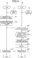
- the flowchart FA of Figure 9 is a flowchart illustrating the operation of the information processing device 4 and the flowchart FB is a flowchart that illustrates the operation of the mobile terminal 3.
- the operations of the information processing device 4 and the mobile terminal 3 will be described by way of example based on a case where the vehicle S should be parked in a parking position corresponding to one parking area of the parking space in which a plurality of parking areas are provided.
- the user stops the vehicle S in the before-parking position near the parking position.
- Figure 10 is a diagram that illustrates a parking space ST1 which is an example of the parking space, a before-parking position PS1 which is an example of the before-parking position in the parking space ST1, and a parking position PS2 which is an example of the parking position in the parking space ST1.
- the parking space ST1 has three parking areas, i.e., a parking area AR1, a parking area AR2, and a parking area AR3 as parking areas in which a vehicle can be parked.
- a parking area AR1 and the parking area AR3 are already parked.
- the user determines the parking position PS2 of the parking area AR2 as the position in which parking of the vehicle S is desired, and causes the vehicle S to be stopped at the before-parking position PS1 near the parking position PS2.
- step S1 After having caused the vehicle S to be stopped at the before-parking position, the user operates the operation input unit 34 of the information processing device 4 and changes the operation mode of the information processing device 4 to the parking mode (step S1).
- step SA1 When the operation mode has been changed to the parking mode by the user, the information processing device control unit 30 of the information processing device 4 performs a parking position determination process (step SA1).
- the parking position determination process is a process of identifying the parking area in which the vehicle S can be parked and deciding on the parking position.
- the information processing device control unit 30 identifies the current position of the vehicle S (before-parking position) on the basis of the information input from the GPS unit 35, the information input from the relative azimuth detection unit 36, and the information included in the map data 33a.
- the method of identifying the current position of the vehicle S may be any method and any pieces of information other than those mentioned above may be used. For example, when the current position of the vehicle S is identified, information based on signals of positioning satellite systems such as GLONASS, Galileo, Beidou, and QZSS (Michibiki) may be used.
- the information processing device control unit 30 identifies the parking area that exists near the current position of the vehicle S and allows parking of the vehicle S on the basis of the captured image data input from each of the cameras provided in the vehicle S, the information of the map data 33a, and the like.
- the information processing device control unit 30 uses the parking map information to identify the parking area.
- the method of identifying the parking area existing near the current position of the vehicle S may be any method.
- the information processing device control unit 30 determines, as the parking position, the position corresponding to the parking area that has been identified.
- step SA2 After having determined the parking position in step SA1, the information processing device control unit 30 performs an automatic driving route information generation process (step SA2).
- the automatic driving route information generation process is a process of generating the automatic driving route information that includes the path information indicative of the path from the current position in which the vehicle S is stopped (before-parking position) to the parking position that has been determined in step SA1.
- the information processing device control unit 30 computes the path of the vehicle S from the current position of the vehicle S to the parking position on the basis of the captured image data input from each of the cameras provided in the vehicle S, the pieces of information of the map data 33a, and the like.
- the information processing device control unit 30 computes, for example, a path KD as the path of the vehicle S from the before-parking position to the parking position.
- the path KD illustrated by way of example in Figure 10 has a path KD1 from the before-parking position PS1 to a position MD on the path KD, and a path KD2 from the position MD to the parking position PS2.
- the path KD1 is a path on which the vehicle S "moves forward" while turning to the left from the before-parking position PS1 toward the direction of travel and then temporarily stops at the position MD.
- the path KD2 is a path on which the vehicle S "moves backward” while turning to the left from the position MD toward the direction of travel and then stops in the parking position PS2.
- the information processing device control unit 30 defines a virtual coordinate system whose origin is the current position of the vehicle S and deploys the line segments corresponding to the path of the vehicle S onto the virtual coordinate system that has been defined, generates the path information on the basis of the line segments that have been deployed, and generates the automatic driving route information that includes the path information.
- the user After having changed the operation mode of the information processing device 4 to the parking mode in step S1, the user gets off the vehicle S in a state where the user carries the mobile terminal 3 and thus gets out of the vehicle S. Note that the user does not always have to get off the vehicle S but, in this embodiment, for the sake of explanation, the description will be provided on the assumption that the user gets off the vehicle S.
- step S2 After having got out of the vehicle, the user operates the touch panel 9 of the mobile terminal 3 and starts up the dedicated application AP (step S2). Note that the user places the orientation of the housing 8 of the mobile terminal 3 in the "portrait orientation" when starting up the dedicated application AP.
- the terminal control unit 20 of the mobile terminal 3 performs the processing of the flowchart FB by the function of the dedicated application AP that has been started up by the user in step S2.
- the terminal control unit 20 displays a lock screen GM1 (see Figure 11 ) on the touch panel 9 (step SB1).
- the entity that performs the process of displaying the screen on the touch panel 9 the process of changing the content of the screen in accordance with the operation by the user and other events, and the process of changing the screen displayed on the touch panel 9 from one screen to another screen is the terminal control unit 20 even when specific explanations are not given.
- the terminal control unit 20 monitors whether or not any input that instructs transition to the vehicle propulsion control mode has been made on the lock screen GM1 (step SB2) .
- Figure 11 is a diagram that illustrates the lock screen GM1.
- the lock screen GM1 is a screen for accepting an input of the instruction to make a transition of the operation mode of the mobile terminal 3 to the vehicle propulsion control mode (which will be described later).
- the terminal control unit 20 causes the operation mode to make a transition to the vehicle propulsion control mode and changes the screen displayed on the touch panel 9 from the lock screen GM1 to a vehicle control screen GM2 (which will be described later).
- the operation mode is in the vehicle propulsion control mode, the user makes an operation on the touch panel 9 and can thereby control the propulsion of the vehicle S.
- a slide unit SU1 is displayed on the lock screen GM1.
- the slide unit SU1 has a slide bar BR1 and a slide button SB1.
- the slide bar BR1 is a strip-like object extending in the right-left direction which explicitly indicates the range in which the slide button SB1 is movable and regulates the movement of the slide button SB1.
- the slide button SB1 is a button on which the user can make a touch operation (the touch-operable button will be hereinafter expressed as a "touch operation button”) and is adapted to be moved along the slide bar BR1 in accordance with a swipe operation of the user. As illustrated in Figure 11 , when a touch operation is not performed by the user, a state is maintained where the slide button SB1 is positioned at the left end BRla (one end) of the slide bar BR1. The slide button SB1 is movable in the range from the left end BRla of the slide bar BR1 to the right end BRlb (the other end) thereof.
- Figure 12 is a diagram used in an explanation of the screen displayed on the touch panel 9.
- Figure 12 a portion of the finger of the user operating the screen is illustrated along with the screen displayed on the touch panel 9.
- the state J1 of Figure 12 indicates the lock screen GM1 in a state where the user is not performing the touch operation.
- the user makes a touch operation on the slide button SB1 using his/her finger positioned at the left end BRla of the slide bar BR1 on the lock screen GM1 in the state J1.
- the user performs the swipe operation and causes the slide button SB1 to be moved rightward along the slide bar BR1.
- the swipe operation means an operation of moving the position with which a finger is in contact with while maintaining the state where the finger is in contact with the touch panel 9.
- the terminal control unit 20 follows the position with which the finger is in contact and moves the slide button SB1 along the slide bar BR1.
- the state J2 of Figure 12 illustrates the lock screen GM1 in a state where the slide button SB1 is positioned at the central portion of the slide bar BR1 by the swipe operation.
- a vehicle control screen GM2 (specifically, the overhead image display screen GM2a which will be described later) is displayed as the background on the lock screen GM1.
- the terminal control unit 20 masks the overhead image display screen GM2a displayed as the background by a dark black mask image that covers the entire background.
- the terminal control unit 20 makes the color of the mask image lighter when the separation distance between the left end BRla of the slide bar BR1 and the slide button SB1 becomes longer.
- the terminal control unit 20 makes the color of the mask image lighter when the separation distance between the left end BRla of the slide bar BR1 and the slide button SB1 becomes longer.
- the user who performs the swipe operation moves the slide button SB1 to the right end BRlb of the slide bar BR1 and maintains the state where the slide button SB1 is positioned at the right end BRlb for a predetermined period of time (for example, three seconds).
- a predetermined period of time for example, three seconds.
- the state J3 of Figure 12 indicates the lock screen GM1 in a state where the slide button SB1 is positioned at the right end BRlb of the slide bar BR1.
- the state J3 continues for a predetermined period of time, the input of the instruction on the transition to the vehicle propulsion control mode is completed.
- the background overhead image display screen GM2a becomes clearer when the slide button SB1 is positioned more rightward.
- the terminal control unit 20 moves the slide button SB1 to the left end BRla of the slide bar BR1 in response to the ending of the swipe operation.
- step SB2 the terminal control unit 20 monitors, on the basis of the input from the touch panel 9, whether or not the slide button SB1 has been positioned at the right end BRlb of the slide bar BR1 for the predetermined period of time. In addition, when the slide button SB1 has been positioned at the right end BRlb of the slide bar BR1 for the predetermined period of time, the terminal control unit 20 determines that the input of the instruction on the transition to the vehicle propulsion control mode has been made.
- the input of the instruction on the transition to the vehicle propulsion control mode is completed only after the slide button SB1 is positioned at the right end BRlb of the slide bar BR1 for the predetermined period of time.
- step SB2 When it has been determined in step SB2 that the input of the instruction on the transition to the vehicle propulsion control mode was made (YES in step SB2), the terminal control unit 20 causes the operation mode to make a transition to the vehicle propulsion control mode (step SB3).
- the terminal control unit 20 changes the screen displayed on the touch panel 9 from the lock screen GM1 to the vehicle control screen GM2 (step SB4).
- the state J4 of Figure 12 indicates the vehicle control screen GM2 immediately after the screen displayed on the touch panel 9 was changed from the lock screen GM1 to the vehicle control screen GM2. Note that the orientation of the housing 8 of the mobile terminal 3 is in the "portrait orientation" immediately after the screen was changed to the vehicle control screen GM2.
- either screen of the overhead image display screen GM2a or the outside-of-vehicle image display screen GM2b is displayed depending on the orientation of the housing 8.
- the orientation of the housing 8 is in the "portrait orientation" immediately after the screen was changed to the vehicle control screen GM2, and the overhead image display screen GM2a is displayed on the touch panel 9 as the vehicle control screen GM2.
- the terminal control unit 20 causes the slide button SB1 on the lock screen GM1 to change into a propulsion control button QB (operation button) which is a touch operation button in response to the switching of the screens in the course of the transition of the operation mode, and displays the propulsion control button QB on the vehicle control screen GM2.
- the terminal control unit 20 instead of additionally displaying the propulsion control button QB as the button different than the slide button SB1, causes the slide button SB1 positioned at the right end BRlb of the slide bar BR1 to function as the propulsion control button QB in response to the change of the screen without changing the position.
- the propulsion control button QB is positioned at the right end BRlb of the slide bar BR1 on the lock screen GM1, and the propulsion control button QB is in the state where it has been subjected to the touch operation by the user.
- the information processing device control unit 30 of the information processing device 4 and the terminal control unit 20 of the mobile terminal 3 perform the vehicle propulsion control processing in cooperation (steps SA3 and SB5).
- steps SA3 and SB5 explanations will be provided with regard to the vehicle propulsion control processing, by way of separate processes, i.e., a process associated with the control of the propulsion of the vehicle S and a process associated with the display on the touch panel 9.
- the terminal control unit 20 establishes the communication channel between the mobile terminal 3 and the information processing device 4 in accordance with the standards of Wi-Fi and establishes a state where communication can be performed between the mobile terminal 3 and the information processing device 4.
- Information necessary for establishing the communication channel (for example, a pass word, etc., necessary for the information processing device 4 to authenticate the mobile terminal 3) is registered in advance.
- the terminal control unit 20 of the mobile terminal 3 controls the terminal communication unit 21 while a touch operation is being performed on the propulsion control button QB displayed on the vehicle control screen GM2 and transmits a propulsion instruction signal to the information processing device 4. Meanwhile, the terminal control unit 20 stops the transmission of the propulsion instruction signal in response to the ending of the touch operation on the propulsion control button QB. Specifically, the terminal control unit 20 does not transmit the propulsion instruction signal to the information processing device 4 while a touch operation is not performed on the propulsion control button QB.
- the screen displayed as the vehicle control screen GM2 changes depending on the orientation of the housing 8 of the mobile terminal 3 and the position of the propulsion control button QB on the vehicle control screen GM2 moves in accordance with the operation of the user.
- the terminal control unit 20 transmits the propulsion instruction signal to the information processing device 4 regardless of switching of the screens displayed on the vehicle control screen GM2 and regardless of the position of the propulsion control button QB while the touch operation is being performed on the propulsion control button QB, and does not transmit the propulsion instruction signal to the information processing device 4 while the touch operation is not performed.
- the information processing device control unit 30 of the information processing device 4 outputs, to the vehicle drive control device 5, the automatic driving route information generated by the automatic driving route information generation process in step SA2. Further, the information processing device control unit 30 outputs a drive instruction signal to the vehicle drive control device 5 while the information processing device control unit 30 is receiving the propulsion instruction signal from the mobile terminal 3. Meanwhile, the information processing device control unit 30 does not output the drive instruction signal to the vehicle drive control device 5 while the information processing device control unit 30 is not receiving the propulsion instruction signal from the mobile terminal 3.
- the vehicle drive control device 5 performs the following processing on the basis of the drive instruction signal input from the information processing device 4. Specifically, the vehicle drive control device control unit 50 of the vehicle drive control device 5 causes the vehicle S to move along the path indicated by the path information on the basis of the path information included in the automatic driving route information while the drive instruction signal is being input from the information processing device 4. Meanwhile, when a state where the drive instruction signal is being input is exited and a state is entered where it is not being input, the vehicle drive control device control unit 50 controls the vehicle S and stops the movement of the vehicle S.
- the vehicle drive control device control unit 50 starts the vehicle S and causes the vehicle S to move along the path indicated by the path information.
- the vehicle drive control device control unit 50 causes the vehicle S to move along the path KD while the drive instruction signal is being input.
- the vehicle drive control device control unit 50 brakes the vehicle S and stops the movement of the vehicle S. In this state, when the drive instruction signal is input again, the vehicle drive control device control unit 50 starts the vehicle S positioned at the position PS3 and causes the vehicle S to move along the path KD.
- the vehicle S moves along the path while the user is performing the touch operation on the propulsion control button QB on the vehicle control screen GM2, and the movement of the vehicle S is stopped while the user does not perform the touch operation on the propulsion control button QB.
- the user wants to stop the movement of the vehicle S for a certain reason, the user can stop the movement of the vehicle S quickly by performing a simple task of ending the touch operation on the propulsion control button QB.
- two operation modes are provided, i.e., a first mode and a second mode.
- the user can switch the operation modes between the first and second modes by a predetermined method.
- the flowchart FC of Figure 13 is a flowchart that illustrates the operation of the mobile terminal 3 when the operation mode is in the first mode.
- the flowchart FD of Figure 14A and the flowchart FE of Figure 14B are flowcharts that each illustrates the operation of the information processing device 4 when the operation mode is in the first mode.
- the terminal control unit 20 of the mobile terminal 3 controls the terminal communication unit 21 in response to the transition to the vehicle propulsion control mode and transmits, to the information processing device 4, vehicle propulsion control mode information indicative of the fact that transition has been made to the vehicle propulsion control mode (step SC1).
- the information processing device control unit 30 of the information processing device 4 receives the vehicle propulsion control mode information (step SD1).
- the information processing device control unit 30 starts display of the composite image G on the display device 32 in response to the reception of the vehicle propulsion control mode information on the basis of the captured image data input from each of the cameras provided in the vehicle S (step SD2).
- Figure 15 is a diagram in which the display device 32 on which the composite image G is displayed is viewed from the front.
- the shape of the display area AR in which display of an image in the display device 32 is possible is rectangular with a short side in an up-down direction and a long side in a right-left direction.
- the up-down direction is a direction that corresponds to the vertical direction
- the right-left direction is a direction that corresponds to the direction orthogonal to the vertical direction.
- the composite image G has an overhead image G1 and an outside-of-vehicle image G2.
- the overhead image G1 is an image of a bird's eye view of the vehicle S. As illustrated in Figure 15 , the overhead image G1 is a rectangular image that has a long side in the up-down direction and a short side in the right-left direction and is displayed on the left portion of the display area AR. At the lower right portion of the overhead image G1, the mark M1 is displayed which explicitly indicates that the displayed image is the overhead image G1.
- the outside-of-vehicle image G2 is an image based on a result of imaging of the outside of the vehicle by one outside-of-vehicle imaging camera out of the outside-of-vehicle imaging cameras. As illustrated in Figure 15 , the outside-of-vehicle image G2 is a rectangular image that has a short side in the up-down direction and a long side in the right-left direction. The outside-of-vehicle image G2 is displayed in the right portion of the display area AR in a state where the right side of the overhead image G1 and the left side of the outside-of-vehicle image G2 are overlapped with each other. At the lower right portion of the outside-of-vehicle image G2, the mark M2 is displayed.
- the mark M2 is a mark that explicitly indicates the outside-of-vehicle imaging camera which is the source of the output of the captured image data corresponding to the outside-of-vehicle image G2 displayed on the display device 32 among the outside-of-vehicle imaging cameras.
- the mark M2 is a mark obtained by adding a decoration explicitly indicating that the front side of the vehicle S has been imaged to a symbol representing the vehicle S.
- the user can accurately recognize, by referring to the mark M2, which outside-of-vehicle imaging camera has provided the result of imaging that the outside-of-vehicle image G2 displayed on the display device 32 is based upon amongst the outside-of-vehicle imaging cameras.
- the information processing device control unit 30 acquires the captured image data input from each of the overhead cameras. Subsequently, image data of a bird's eye view of the vehicle S (hereinafter referred to as "overhead image data") is generated on the basis of the captured image data input from each of the overhead cameras.
- the image of the bird's eye view of the vehicle S is an image that indicates how the vehicle S as a whole and regions around the vehicle S are viewed from above.
- the image data is bitmap data in which dots having information on color (for example, information indicative of the color components of each color of RGB as gradation values of a predetermined gradation) are arranged in a dot matrix at a predetermined resolution.
- the overhead image data is image data at a predetermined resolution with a size corresponding to the size of the overhead image G1 (the length in the up-down direction and the length in the right-left direction).
- the process of generating the overhead image data on the basis of the captured image data input from the overhead camera is performed properly by existing technology.
- Each of the overhead cameras performs imaging in synchronization with each other and outputs the captured image data based on the result of the synchronized imaging to the information processing device control unit 30.
- Each of the overhead cameras performs the execution of the imaging and the output of the captured image data at a predetermined cycle (for example, 10 milliseconds).
- the information processing device control unit 30 acquires the captured image data input from each of the overhead cameras at a cycle corresponding to the predetermined cycle and generates the overhead image data on the basis of the captured image data that has been acquired.
- the information processing device control unit 30 adds image data corresponding to the mark M1 to an appropriate position and generates the overhead image data.
- each of the outside-of-vehicle imaging cameras performs the imaging at a predetermined cycle and outputs the captured image data based on the result of the imaging to the information processing device control unit 30.
- the information processing device control unit 30 selects one outside-of-vehicle imaging camera from among the outside-of-vehicle imaging cameras, acquires the captured image data input from the outside-of-vehicle imaging camera that has been selected, and generates the image data of the outside-of-vehicle image G2 (hereinafter referred to as "outside-of-vehicle image data") on the basis of the captured image data.
- the information processing device control unit 30 generates the outside-of-vehicle image data at a cycle corresponding to the predetermined cycle.
- the information processing device control unit 30 adds image data corresponding to the mark M2 to an appropriate position and generates the outside-of-vehicle image data.
- the outside-of-vehicle image data is image data at a predetermined resolution with a size corresponding to the size of the outside-of-vehicle image G2 (the length in the up-down direction and the length in the right-left direction).
- the information processing device control unit 30 performs the generation of the overhead image data based on the input from the overhead camera and the generation of the outside-of-vehicle image data based on the input from the outside-of-vehicle imaging camera in a synchronized manner at a predetermined cycle.
- the information processing device control unit 30 combines, at a predetermined cycle, the overhead image data that has been generated and the outside-of-vehicle image data that has been generated corresponding to the positional relationship between the overhead image G1 and the outside-of-vehicle image G2 and generates composite image data of the composite image G.
- the information processing device control unit 30 controls the display device 32 on the basis of the composite image data that has been generated and causes the display device 32 to display the composite image G based on the composite image data.
- the composite image G obtained by combining the overhead image G1 and the outside-of-vehicle image G2 is displayed on the display device 32.
- the content of the overhead image G1 changes at any time on the basis of the result of the imaging by the overhead camera and the content of the outside-of-vehicle image G2 changes at any time on the basis of the result of the imaging by the outside-of-vehicle imaging camera that has been selected.
- the information processing device control unit 30 generates the composite image data at the predetermined cycle and causes the display device 32 to display the composite image G.
- the information processing device control unit 30 transmits the composite image data that has been generated to the mobile terminal 3 at the predetermined cycle (step SD3).
- the first mode differs from the second mode which will be described later in that, in the first mode, the information processing device control unit 30 transmits the composite image data to the mobile terminal 3.
- the terminal control unit 20 of the mobile terminal 3 starts reception of the composite image data that the information processing device 4 transmits (step SC2) and, on the basis of the composite image data that has been received, causes the touch panel 9 to display the overhead image display screen GM2a (step SC3). Note that at the point in time at which the process at step SC3 is performed, the orientation of the housing of the mobile terminal 3 is in the "portrait orientation.”
- the overhead image display screen GM2a is, as illustrated in the state J3 of Figure 12 , a screen on which the overhead image G1 is displayed and the propulsion control button QB is displayed in a superposed manner upon the overhead image G1.
- step SC3 the terminal control unit 20 performs the following process and causes the touch panel 9 to display the overhead image display screen GM2a. Specifically, the terminal control unit 20 extracts the overhead image data from the composite image data for each of the pieces of composite image data received at the predetermined cycle. An area of the overhead image data in the composite image data is defined in advance and the terminal control unit 20 separates from the composite image data the data pertaining to the area of the overhead image data in the composite image data and thereby extracts the overhead image data.
- the terminal control unit 20 subjects the extracted overhead image data to necessary image processing (a process of adjusting the resolution, a process of adjusting the size, etc.) and causes the touch panel 9 to display the overhead image display screen GM2a on the basis of the overhead image data that has been subjected to the image processing.
- necessary image processing a process of adjusting the resolution, a process of adjusting the size, etc.
- the content of the overhead image G1 displayed on the overhead image display screen GM2a changes at any time on the basis of the result of the imaging by the overhead camera in synchronization with the overhead image G1 displayed on the display device 32 of the information processing device 4.
- the overhead image G1 is a rectangular image having the long side in the up-down direction (the direction that corresponds to the vertical direction) and the short side in the right-left direction (the direction that corresponds to the direction orthogonal to the vertical direction). Also, when the orientation of the housing 8 of the mobile terminal 3 is in the "portrait orientation," the touch panel 9 is placed in a state where the direction of the long side is in the vertical direction and the direction of the short side is in the direction orthogonal to the vertical direction.
- the orientation of the housing 8 is in the "portrait orientation," by displaying the overhead image G1 on the touch panel 9, it is possible to take advantage of the feature that the overhead image G1 has its long side in the up-down direction and its short side in the right-left direction and display the overhead image G1 using the entire display area of the touch panel 9 without unnecessarily reducing the overhead image G1.
- the overhead image G1 can be easily seen by the user and the convenience for the user is improved.
- the terminal control unit 20 monitors whether the orientation of the housing 8 of the mobile terminal 3 has changed from the "portrait orientation” to the “landscape orientation” on the basis of the input from the housing state detection unit 23 (step SC4).
- the terminal control unit 20 selects one outside-of-vehicle imaging camera from among the outside-of-vehicle imaging cameras in accordance with a predetermined order of priority corresponding to the state of the vehicle S (step SC5).
- the order of priority is an order of priority according to which the outside-of-vehicle imaging camera that can image the direction of travel of the vehicle S will occupy a higher place.
- the front imaging camera CA1 when the vehicle S is "moving forward" to the front side, the front imaging camera CA1 will occupy the highest place in the order of priority and, when the vehicle S is "moving forward" toward the front right side, the front right-side imaging camera CA2 will occupy the highest place in the order of priority, and, when the vehicle S is "moving backward" to the rear side, the rear imaging camera CA5 will occupy the highest place in the order of priority.
- the vehicle S is performing the automatic vehicle movement, it is expected that the user in many cases wants to recognize the state of the direction of travel of the vehicle S.
- the order of priority is an order of priority according to which a camera that can image the object close to the vehicle S will occupy a higher place.
- the object close to the vehicle S is, for example, a vehicle that has already been parked at the parking area adjacent to the parking area in which parking should be made by the automatic vehicle movement and, for example, a person other than the user.
- the user in many cases wants to recognize the object and recognize the positional relationship between the object and the vehicle S.
- the terminal control unit 20 communicates with the information processing device 4 as appropriate and acquires information necessary for selecting the outside-of-vehicle imaging camera according to a predetermined order of priority in step SC5.
- the terminal control unit 20 After having selected the one outside-of-vehicle imaging camera in step SC5, the terminal control unit 20 transmits selected-camera information indicative of the outside-of-vehicle imaging camera that has been selected (for example, the identification information for identifying the outside-of-vehicle imaging camera that has been selected) to the information processing device 4 (step SC6).
- selected-camera information indicative of the outside-of-vehicle imaging camera that has been selected for example, the identification information for identifying the outside-of-vehicle imaging camera that has been selected
- the information processing device control unit 30 of the information processing device 4 receives the selected-camera information (step SE1).
- the information processing device control unit 30 changes the outside-of-vehicle image G2 that should be displayed on the display device 32 to the image based on the result of the imaging by the outside-of-vehicle imaging camera indicated by the selected-camera information received in step SE1 (step SE2).
- step SE2 the information processing device control unit 30 combines the overhead image data and the outside-of-vehicle image data based on the result of the imaging by the outside-of-vehicle imaging camera indicated by the selected-camera information to generate the composite image data, and displays the composite image G on the basis of the composite image data that has been generated.
- the information processing device control unit 30 performs continuously the transmission of the composite image data corresponding to the composite image G to be displayed on the display device 32.
- a state is entered where the composite image data that the information processing device 4 transmits to the mobile terminal 3 includes the outside-of-vehicle image data based on the result of the imaging by the outside-of-vehicle imaging camera that has been selected in step SC5.
- the terminal control unit 20 of the mobile terminal 3 causes the touch panel 9 to display the outside-of-vehicle image display screen GM2b on the basis of the composite image data received from the information processing device 4 (step SC7).
- the composite image data used in the display of the outside-of-vehicle image display screen GM2b is the composite image data that includes the outside-of-vehicle image data based on the result of the imaging by the outside-of-vehicle imaging camera that has been selected in step SC5.
- the state J6 of Figure 12 illustrates the outside-of-vehicle image display screen GM2b.
- the outside-of-vehicle image display screen GM2b is, as illustrated by the state J6 of Figure 12 , a screen on which the outside-of-vehicle image G2 is displayed and the propulsion control button QB is displayed in a superposed manner on the outside-of-vehicle image G2.
- step SC7 the terminal control unit 20 extracts the outside-of-vehicle image data from the composite image data for each of the pieces of composite image data received at the predetermined cycle.
- the area of the outside-of-vehicle image data in the composite image data is defined in advance and the terminal control unit 20 separates the data pertaining to the area of the outside-of-vehicle image data in the composite image data from the composite image data and thereby extracts the outside-of-vehicle image data.
- the terminal control unit 20 subjects the outside-of-vehicle image data that has been extracted to necessary image processing (a process of adjusting the resolution, a process of adjusting the size, etc.) and causes the touch panel 9 to display the outside-of-vehicle image display screen GM2b on the basis of the outside-of-vehicle image data that has been subjected to the image processing.
- necessary image processing a process of adjusting the resolution, a process of adjusting the size, etc.
- the content of the outside-of-vehicle image G2 displayed on the outside-of-vehicle image display screen GM2b changes at any time on the basis of the result of the imaging by the outside-of-vehicle imaging camera that has been selected in step SC5 in synchronization with the outside-of-vehicle image G2 displayed on the display device 32 of the information processing device 4.
- the outside-of-vehicle image display screen GM2b is displayed on the touch panel 9 in place of the overhead image display screen GM2a.
- the operation of changing the orientation of the housing 8 of the mobile terminal 3 is an operation that can be performed accurately in a simple manner even when the user grasps the mobile terminal 3 by one hand, and the convenience for the user is high.
- the outside-of-vehicle image display screen GM2b displayed in response to the orientation of the housing 8 of the mobile terminal 3 having changed from the "portrait orientation" to the "landscape orientation” is a screen based on the result of the imaging by the outside-of-vehicle imaging camera that has been selected in accordance with the predetermined order of priority corresponding to the state of the vehicle S.
- the outside-of-vehicle image G2 displayed on the outside-of-vehicle image display screen GM2b is likely to be the image based on the result of imaging by the outside-of-vehicle imaging camera desired by the user, and the convenience for the user is high.
- outside-of-vehicle image G2 is a rectangular image having the long side in the right-left direction (the direction that corresponds to the direction orthogonal to the vertical direction) and the short side in the up-down direction (the direction that corresponds to the vertical direction). Also, when the orientation of the housing 8 of the mobile terminal 3 is in the "landscape orientation," the touch panel 9 is placed in a state where the direction of the long side is in the direction orthogonal to the vertical direction and the direction of the short side is in the vertical direction.
- the outside-of-vehicle image G2 when the orientation of the housing 8 is in the "landscape orientation," by displaying the outside-of-vehicle image G2 on the touch panel 9, it is possible to take advantage of the feature that the outside-of-vehicle image G2 has its long side in the right-left direction and its short side in the up-down direction and display the outside-of-vehicle image G2 using the entire display area of the touch panel 9 without unnecessarily reducing the outside-of-vehicle image G2. As a result, the outside-of-vehicle image G2 can be easily seen by the user and the convenience for the user is improved.
- the terminal control unit 20 monitors whether the housing 8 makes either motion of the "rightward motion” or the “leftward motion” (step SC8) and monitors whether or not the orientation of the housing 8 has been placed in the "portrait orientation” (step SC9).
- step SC3 the terminal control unit 20 causes the touch panel 9 to display the overhead image display screen GM2a on the basis of the composite image data received from the information processing device 4.
- the overhead image display screen GM2a is displayed on the touch panel 9 in place of the outside-of-vehicle image display screen GM2b.
- the user wants to view the overhead image G1 in place of the outside-of-vehicle image G2
- the user can make the overhead image display screen GM2a displayed by performing the simple task of changing the orientation of the housing 8 of the mobile terminal 3 and can view the overhead image G1.
- the operation of changing the orientation of the housing 8 of the mobile terminal 3 is an operation that can be accurately performed in a simple manner even when the user is grasping the mobile terminal 3 by one hand, and the convenience for the user is high.
- the overhead image G1 is an image that the user is most frequently views while the automatic vehicle movement is being performed.
- the user can view the overhead image G1 at any appropriate point in time by placing the orientation of the housing 8 of the mobile terminal 3 in the "portrait orientation" and the convenience for the user is high.
- the terminal control unit 20 makes the processing procedure proceed to step SC10. Specifically, the terminal control unit 20 makes the processing procedure proceed to step SC10 when the housing 8 has made the "rightward motion” or the "leftward motion” while the orientation of the housing 8 is in the "landscape orientation.”
- step SC10 the terminal control unit 20 determines whether the motion of the housing 8 was the "rightward motion” or the "leftward motion.” In the case where the motion of the housing 8 was the "rightward motion” (step SC10: "rightward motion"), the terminal control unit 20 selects one outside-of-vehicle imaging camera from among the outside-of-vehicle imaging cameras in accordance with the first order according to the direction in which the outside-of-vehicle imaging camera performs imaging (step SC11).
- the first order is given as "the front side” -> "the front right side” -> “the lateral right side” -> “the rear right side” -> “the rear side” -> “the rear left side” -> “the lateral left side” -> “the front left side” -> “the front side.”
- the first order is the order according to which the direction in which the outside-of-vehicle imaging camera performs imaging changes clockwise.
- step SC11 the terminal control unit 20 selects, according to the first order, the outside-of-vehicle imaging camera that performs imaging in the direction defined by the order that is next to the direction in which the outside-of-vehicle imaging camera selected prior to the process at step SC11 being performed performs imaging.
- the terminal control unit 20 selects the front right-side imaging camera CA2 in accordance with the first order in step SC11.
- the terminal control unit 20 selects the rear left-side imaging camera CA6 in accordance with the first order in step SC11.
- the terminal control unit 20 After having selected the outside-of-vehicle imaging camera in step SC11, the terminal control unit 20 transmits the selected-camera information indicative of the outside-of-vehicle imaging camera that has been selected to the information processing device 4 (step SC12). After the process at step SC12, the terminal control unit 20 makes the processing procedure go back to step SC8.
- the information processing device 4 performs the processing of the flowchart FE of Figure 14B and changes the outside-of-vehicle image G2 displayed on the display device 32 to the image based on the result of the imaging by the outside-of-vehicle imaging camera indicated by the selected-camera information.
- the combined image data transmitted from the information processing device 4 to the mobile terminal 3 will include the outside-of-vehicle image data based on the result of the imaging by the outside-of-vehicle imaging camera indicated by the selected-camera information.
- the outside-of-vehicle image G2 displayed on the outside-of-vehicle image display screen GM2b of the touch panel 9 of the mobile terminal 3 will be the image based on the result of the imaging by the outside-of-vehicle imaging camera that has been selected in step SC11.
- the user can change the outside-of-vehicle image G2 displayed on the outside-of-vehicle image display screen GM2b by performing a simple task of causing the housing 8 to make a "rightward motion" and the convenience for the user is high.
- the housing 8 has made the "rightward motion”
- the direction of imaging corresponding to the outside-of-vehicle image G2 displayed on the outside-of-vehicle image display screen GM2b changes clockwise in accordance with the first order.
- the "rightward direction” in which the housing 8 moves in the “rightward motion” and the “clockwise” change are linked with each other and, after having caused the housing 8 to make the “rightward motion," the user can intuitively recognize the direction in which the imaging is performed by the outside-of-vehicle imaging camera providing the result of imaging on which the outside-of-vehicle image G2 displayed on the touch panel 9 is based, so that the convenience for the user is high.
- step SC10 when it has been determined in step SC10 that the motion of the housing 8 was the "leftward motion" (step SC10: "leftward motion"), the terminal control unit 20 performs the following process.
- the terminal control unit 20 selects one outside-of-vehicle imaging camera from among the outside-of-vehicle imaging cameras in accordance with the second order corresponding to the direction in which the outside-of-vehicle imaging camera performs imaging (step SC13).
- the second order is given as "the front side” -> "the front left side” -> “the lateral left side” -> “the rear left side” -> “the rear side” -> “the rear right side” -> “the lateral right side” -> “the front right side” -> “the front side.”
- the second order is the order according to which the direction in which the outside-of-vehicle imaging camera performs imaging changes counterclockwise.
- step SC13 the terminal control unit 20 selects the outside-of-vehicle imaging camera that performs imaging in the direction of the next place in the order that is next to the direction in which the outside-of-vehicle imaging camera selected prior to the process in step SC13 being performed performs the imaging in accordance with the second order.
- the terminal control unit 20 selects the front left-side imaging camera CA8 in accordance with the second order in step SC13.
- the terminal control unit 20 selects the rear right-side imaging camera CA4 in accordance with the second order in step SC13.
- the terminal control unit 20 After having selected the outside-of-vehicle imaging camera in step SC13, the terminal control unit 20 transmits the selected-camera information indicative of the outside-of-vehicle imaging camera that has been selected to the information processing device 4 (step SC14). After the process of step SC14, the terminal control unit 20 makes the processing procedure go back to step SC8.
- the information processing device 4 performs the processing of the flowchart FE of Figure 14B and changes the outside-of-vehicle image G2 displayed on the display device 32 to the image based on the result of the imaging by the outside-of-vehicle imaging camera indicated by the selected-camera information.
- the combined image data transmitted from the information processing device 4 to the mobile terminal 3 will include the outside-of-vehicle image data based on the result of the imaging by the outside-of-vehicle imaging camera indicated by the selected-camera information.
- the outside-of-vehicle image G2 displayed on the outside-of-vehicle image display screen GM2b of the touch panel 9 of the mobile terminal 3 will be the image based on the result of the imaging by the outside-of-vehicle imaging camera that has been selected in step SC11.
- the user can change the outside-of-vehicle image G2 displayed on the outside-of-vehicle image display screen GM2b by performing a simple task of causing the housing 8 to make the "leftward motion" and the convenience for the user is high.
- the housing 8 has made the "leftward motion”
- the direction of imaging corresponding to the outside-of-vehicle image G2 displayed on the outside-of-vehicle image display screen GM2b changes counterclockwise in accordance with the second order.
- the "leftward direction” in which the housing 8 moves in the “leftward motion” and the “counterclockwise” change are linked with each other and, after causing the housing 8 to make the "leftward motion," the user can recognize intuitively the direction in which the imaging is performed by the outside-of-vehicle imaging camera providing the result of imaging on which the outside-of-vehicle image G2 displayed on the touch panel 9 is based, and the convenience for the user is high.
- the first mode has been described in the foregoing. In the first mode, in comparison with the second mode which will be described later, it is not necessary for the information processing device 4 to extract the overhead image data and the outside-of-vehicle image data from the composite image data, so that the load on the information processing device 4 is smaller.
- the flowchart FF of Figure 16 is a flowchart that illustrates the operation of the mobile terminal 3 when the operation mode is in the second mode.
- the flowchart FG of Figure 17A , the flowchart FH of Figure 17B , and the flowchart FI of Figure 17C are flowcharts that each illustrates the operation of the information processing device 4 when the operation mode is in the second mode.
- the terminal control unit 20 of the mobile terminal 3 controls the terminal communication unit 21 in response to the transition to the vehicle propulsion control mode and transmits, to the information processing device 4, the vehicle propulsion control mode information indicative of the fact that the transition has been made to the vehicle propulsion control mode (step SF1).
- the information processing device control unit 30 of the information processing device 4 receives the vehicle propulsion control mode information (step SG1).
- the information processing device control unit 30 in response to the reception of the vehicle propulsion control mode information, starts display of the composite image G on the display device 32 on the basis of the captured image data input from each of the outside-of-vehicle imaging cameras and each of the overhead cameras (step SG2).
- the terminal control unit 20 of the mobile terminal 3 transmits, continuously with the transmission of the vehicle propulsion control mode information in step SF1, portrait orientation information indicative of the fact that the orientation of the housing 8 of the mobile terminal 3 is in the "portrait orientation" (step SF2). Note that at the point in time at which the process of step SC3 is performed, the orientation of the housing of the mobile terminal 3 is in the "portrait orientation.”
- the information processing device control unit 30 of the information processing device 4 receives the portrait orientation information (step SH1).
- the information processing device control unit 30 starts transmission of the overhead image data to the mobile terminal 3 in response to the reception of the portrait orientation information (step SH2).
- step SH2 the information processing device control unit 30 extracts the overhead image data from the composite image data generated at the predetermined cycle. Subsequently, the information processing device control unit 30 subjects the extracted overhead image data to image processing in accordance with the resolution and the size of the touch panel 9 of the mobile terminal 3 and transmits the overhead image data that has been subjected to the image processing to the mobile terminal 3. The information processing device control unit 30 performs the transmission of the overhead image data at a cycle corresponding to the cycle in which the composite image data is generated.
- the terminal control unit 20 stops transmission of the outside-of-vehicle image data and then starts the transmission of the overhead image data.
- the terminal control unit 20 of the mobile terminal 3 starts reception of the overhead image data (step SF3).
- terminal control unit 20 causes the touch panel 9 to display the overhead image display screen GM2a on which the overhead image G1 is displayed on the basis of the overhead image data reception of which was started in step SF3 (step SF4).
- the content of the overhead image G1 displayed on the overhead image display screen GM2a changes at any time on the basis of the result of imaging of the overhead camera in synchronization with the overhead image G1 displayed on the display device 32 of the information processing device 4.
- the terminal control unit 20 monitors, on the basis of the input from the housing state detection unit 23, whether or not the orientation of the housing 8 of the mobile terminal 3 has changed from the "portrait orientation” to the “landscape orientation” (step SF5).
- the terminal control unit 20 selects one outside-of-vehicle imaging camera from among the outside-of-vehicle imaging cameras in accordance with the predetermined order of priority corresponding to the state of the vehicle S (step SF6).
- the predetermined order of priority is, for example, the order of priority that has been illustrated by way of example in relation to the first mode.
- the terminal control unit 20 transmits, to the information processing device 4, landscape orientation information including the information indicative of the fact that the orientation of the mobile terminal 3 is in the "landscape orientation" and the information indicative of the outside-of-vehicle imaging camera that has been selected in step SF6 (step SF7).
- the information processing device control unit 30 of the information processing device 4 receives the landscape orientation information (step SI1).
- the information processing device control unit 30 changes the outside-of-vehicle image G2 that the display device 32 is made to display to the image based on the result of the imaging by the outside-of-vehicle imaging camera indicated by the selected-camera information included in the landscape orientation information that has been received in step SI1 (step SI2).
- the information processing device control unit 30 stops transmission of the overhead image data to the mobile terminal 3 and starts transmission of the outside-of-vehicle image data (step SI3).
- step SI3 the information processing device control unit 30 extracts the outside-of-vehicle image data from the composite image data generated at the predetermined cycle. Subsequently, the information processing device control unit 30 subjects the outside-of-vehicle image data that has been extracted to image processing according to the resolution and the size of the touch panel 9 of the mobile terminal 3 and transmits the outside-of-vehicle image data that has been subjected to the image processing to the mobile terminal 3. The information processing device control unit 30 performs the transmission of the outside-of-vehicle image data at a cycle corresponding to the cycle at which the composite image data is generated.
- the terminal control unit 20 of the mobile terminal 3 starts the reception of the outside-of-vehicle image data (step SF8). Subsequently, the terminal control unit 20 causes the touch panel 9 to display outside-of-vehicle image display screen GM2b on which the outside-of-vehicle image G2 is displayed on the basis of the outside-of-vehicle image data the reception of which was started in step SF8 (step SF9).
- the content of the outside-of-vehicle image G2 displayed on the outside-of-vehicle image display screen GM2b changes at any time on the basis of the result of imaging of the overhead camera in synchronization with the outside-of-vehicle image G2 displayed on the display device 32 of the information processing device 4.
- the terminal control unit 20 monitors whether the housing 8 has made either motion of the "rightward motion” or the “leftward motion” (step SF10) and monitors whether or not the orientation of the housing 8 has been placed in the "portrait orientation” (step SF11).
- the terminal control unit 20 makes the processing procedure proceed to step SF2.
- the orientation of the housing 8 of the mobile terminal 3 has changed from the "landscape orientation" to the "portrait orientation”
- the overhead image display screen GM2a is displayed on the touch panel 9 in place of the outside-of-vehicle image display screen GM2b. The effect of this fact has been described in the explanation of the first mode.
- the terminal control unit 20 makes the processing procedure proceed to step SC10. That is, the terminal control unit 20 makes the processing procedure proceed to step SF12 when the housing 8 has made the "rightward motion” or the "leftward motion” when the orientation of the housing 8 is in the "landscape orientation.”
- step SF12 the terminal control unit 20 determines whether the motion of the housing 8 was the "rightward motion” or the "leftward motion.” In the case where the motion of the housing 8 was the "rightward motion” (step SF12: "rightward motion"), the terminal control unit 20 selects one outside-of-vehicle imaging camera from among the outside-of-vehicle imaging cameras in accordance with the first order corresponding to the direction in which the outside-of-vehicle imaging camera performs imaging (step SF13).
- the terminal control unit 20 transmits, to the information processing device 4, the landscape orientation information including the information indicative of the fact that the orientation of the mobile terminal 3 is in the "landscape orientation" and the information indicative of the outside-of-vehicle imaging camera selected in step SF13 (step SF14). After the process at step SF14, the terminal control unit 20 makes the processing procedure proceed to step SF10.
- the information processing device 4 performs the processing of the flowchart FI of Figure 17C and changes the outside-of-vehicle image G2 to be displayed on the display device 32 to the image based on the result of the imaging by the outside-of-vehicle imaging camera indicated by the selected-camera information that the landscape orientation information includes. Further, the information processing device 4 starts transmission of the outside-of-vehicle image data based on the result of the imaging by the outside-of-vehicle imaging camera indicated by the selected-camera information to the mobile terminal 3.
- the outside-of-vehicle image G2 displayed on the outside-of-vehicle image display screen GM2b of the touch panel 9 of the mobile terminal 3 becomes the image based on the result of the imaging by the outside-of-vehicle imaging camera that has been selected in step SF13.
- step SF12 when the motion of the housing 8 was the "leftward motion" ("leftward motion” in step SF12), the terminal control unit 20 selects one outside-of-vehicle imaging camera from among the outside-of-vehicle imaging cameras in accordance with the second order corresponding to the direction in which the outside-of-vehicle imaging camera performs imaging (step SF15).
- the terminal control unit 20 transmits, to the information processing device 4, the landscape orientation information including the information indicative of the fact that the orientation of the mobile terminal 3 is in the "landscape orientation" and the information indicative of the outside-of-vehicle imaging camera selected in step SF15 (step SF16). After the process at step SF16, the terminal control unit 20 makes the processing procedure proceed to step SF10.
- the information processing device 4 performs the processing of the flowchart FI of Figure 17C and changes the outside-of-vehicle image G2 to be displayed on the display device 32 to the image based on the result of the imaging by the outside-of-vehicle imaging camera indicated by the selected-camera information that the landscape orientation information includes. Further, the information processing device 4 starts transmission of the outside-of-vehicle image data based on the result of the imaging by the outside-of-vehicle imaging camera indicated by the selected-camera information to the mobile terminal 3.
- the outside-of-vehicle image G2 displayed on the outside-of-vehicle image display screen GM2b of the touch panel 9 of the mobile terminal 3 becomes the image based on the result of the imaging by the outside-of-vehicle imaging camera that has been selected in step SF16.
- the second mode has been described in the foregoing.
- the data amount of the data that the information processing device 4 transmits to the mobile terminal 3 is smaller and the communication efficiency is higher.
- the vehicle control screen GM2 (the overhead image display screen GM2a or the outside-of-vehicle image display screen GM2b) is displayed on the touch panel 9 of the mobile terminal 3.
- the propulsion control button QB is displayed on the vehicle control screen GM2.
- the propulsion control button QB is a button for controlling the propulsion of the vehicle S and the vehicle S is propelled along the path while the touch operation is being performed on the button, and the propulsion of the vehicle S is stopped while the touch operation is not performed on the button.
- the terminal control unit 20 moves the position of the propulsion control button QB following the movement of the position of the touch operation.
- the state where the touch operation is performed on the propulsion control button QB is maintained even when the position of the touch operation is moved in a state where the touch panel 9 is contacted after the touch operation has been made on the propulsion control button QB.
- the state J4 of Figure 12 illustrates the vehicle control screen GM2 immediately after the screen displayed on the touch panel 9 has changed from the lock screen GM1 to the vehicle control screen GM2.
- the state J5 of Figure 12 illustrates the vehicle control screen GM2 after the position of the touch operation has been moved from the position of the touch operation of the state J4.
- the position of the propulsion control button QB moves following the touch position, and the state where the touch operation is performed on the propulsion control button QB is maintained.
- the state J6 of Figure 12 illustrates how the orientation of the mobile terminal 3 is taken out of the state J5 and placed in the landscape orientation and the outside-of-vehicle image display screen GM2b is displayed on the touch panel 9 in place of the overhead image display screen GM2a displayed at the time of the state J5.
- the user maintains the state where the finger that performed the touch operation on the propulsion control button QB in the state J5 is in contact with the touch panel 9.
- the terminal control unit 20 also maintains the state where the propulsion control button QB is displayed when having changed the screen to be displayed on the touch panel 9 from the overhead image display screen GM2a to the outside-of-vehicle image display screen GM2b, moves the position of the propulsion control button QB following the movement of the position of the touch operation, and maintains the state where the touch operation is performed on the propulsion control button QB.
- the above-described processing is performed by the terminal control unit 20, so that the following effect is obtained.
- the state where the touch operation is performed on the propulsion control button QB is maintained.
- the user does not need to continue the touch operation in a pinpoint manner on the particular position when operating the propulsion control button QB, and the convenience for the user is high.
- the user in some cases may change the orientation of the housing 8 of the mobile terminal 3.
- the position where the touch operation is performed is displaced in response to the change in the orientation of the housing 8, the state where the touch operation is performed on the propulsion control button QB is maintained and the convenience for the user is high.
- the terminal control unit 20 continuously displays the propulsion control button QB on the position of the propulsion control button QB at the time of the ending of the touch operation. According to this feature, when the user performs the touch operation on the propulsion control button QB again, the user has only to perform the touch operation at the position at the time of ending of the touch operation and the convenience for the user is high.
- the terminal control unit 20 may perform the following processing in place of the above-described processing. Specifically, when the touch operation on the propulsion control button QB has been ended, the propulsion control button QB may be displayed at a predetermined specific position.
- the predetermined specific position is, for example, a position that corresponds to the right end BRlb of the slide bar BR1 on the lock screen GM1. According to this feature, when the touch operation on the propulsion control button QB has been ended, the propulsion control button QB will be displayed at the same position, so that the user can readily locate the position of the propulsion control button QB and the convenience for the user is improved.
- the terminal control unit 20 changes the image indicative of the propulsion control button QB between when the touch operation is performed on the propulsion control button QB and when the touch operation is not made thereon.
- the propulsion control button QB in the states J4 to J6 of Figure 12 is in a state where the touch operation is made thereon, and the propulsion control button QB in the state J7 of Figure 12 is in a state where the touch operation is not made thereon.
- the image indicative of the propulsion control button QB is composed of a circular image and an annular image surrounding the circular image.
- the annular image may be an image whose appearance changes with the passage of time by animation.
- the image indicative of the propulsion control button QB is a circular image and does not include an annular image.
- the user can accurately recognize in a simplified manner the fact that the touch operation is being performed on the propulsion control button QB and the fact that the touch operation is not being made thereon by viewing the image indicative of the propulsion control button QB.
- the terminal control unit 20 displays a mark indicative of the state of the gear of the vehicle S in a superposed manner on the image representing the vehicle S.
- the terminal control unit 20 displays a mark representing the character "P” in a superposed manner on the image representing the vehicle S, displays a mark representing the character "R” in a superposed manner on the image representing the vehicle S in the case of the reverse (R), displays a mark representing character "D” in a superposed manner on the image representing the vehicle S in the case of the drive (D), displays a mark representing character "N” in a superposed manner on the image representing the vehicle S in the case of the neutral (N), and displays a mark representing character "L” in a superposed manner on the image representing the vehicle S in the case of the low (L).
- the terminal control unit 20 communicates with the information processing device 4 and recognizes
- the user can accurately recognize the state of the gear of the vehicle S by referring to the mark displayed in a superposed manner on the image representing the vehicle S.
- the vehicle S moves to the parking position and stops in the parking position, and thereby the vehicle propulsion control processing of the flowchart FA and the vehicle propulsion control processing of the flowchart FB are completed.
- this fact is notified to the user by a predetermined method.
- the user who is outside the vehicle can leave the vicinity of the vehicle S by using the above-described dedicated remote controller and to turn off the engine and to lock the door.
- the composite image data, the overhead image data, and the outside-of-vehicle image data that the information processing device 4 transmits to the mobile terminal 3 each correspond to the "imaging data based on the result of imaging of the camera provided in the vehicle S.”
- the flowchart FJ of Figure 18 is a flowchart that illustrates the operation of the information processing device 4 and the flowchart FK is a flowchart that illustrates the operation of the mobile terminal 3.
- the operations of the information processing device 4 and the mobile terminal 3 will be described by way of example based on a case where the vehicle S should perform the exit from the parking position corresponding to the one parking area of the parking space.
- the user operates the above-described dedicated remote controller and operates the engine switch to turn on the engine of the vehicle S.
- the engine switch to turn on the engine of the vehicle S
- power is supplied from an accessory power supply to the information processing device 4, and the information processing device 4 is turned on.
- step S3 the user operates the touch panel 9 of the mobile terminal 3 to start up the dedicated application AP (step S3).
- the user at the time of starting the dedicated application AP, places the orientation of the housing 8 of the mobile terminal 3 in the "portrait orientation.”
- the terminal control unit 20 of the mobile terminal 3 performs the processing of the flowchart FK by the function of the dedicated application AP that has been started up by the user in step S3.
- step S4 the user performs a predetermined operation on the touch panel 9 and issues an instruction to cause the touch panel 9 to display the exit start instruction screen.
- the terminal control unit 20 in response to the instruction of step S4, causes the touch panel 9 to display the exit start instruction screen (step SK1).
- the exit start instruction screen is a screen on which an instruction to perform the exit by the automatic vehicle movement can be entered, and the touch operation button on which the touch operation is to be performed when the instruction is to be issued.
- the user operates the touch operation button displayed on the exit start instruction screen (step S5).
- the terminal control unit 20 transmits the exit start instruction information to the information processing device 4 (step SK2).
- the information processing device control unit 30 of the information processing device 4 receives the exit start instruction information (step SJ1).
- the information processing device control unit 30 changes the operation mode of the information processing device 4 to the exit mode in response to the reception of the exit start instruction information (step SJ2).
- the information processing device control unit 30 performs the candidate position determination process (step SJ3).
- the candidate position determination process is a process of determining one or more positions in which the vehicle S moving from the parking position can stop.
- the one or more positions determined in the candidate position determination process are candidates of the positions in which the vehicle S upon the exit should be stopped.
- each of the positions determined in the candidate position determination process will be expressed as a "candidate position.”
- the information processing device control unit 30 performs the same process as the above-described parking position determination process and determines the one or more candidate positions.
- the method of determining the candidate position may be any method.
- step SJ4 After having determined the one or more candidate positions in step SJ3, the information processing device control unit 30 performs a candidate position route information generation process (step SJ4).
- the candidate position route information generation process is a process of generating automatic driving route information that includes the path information indicative of the path from the parking position to the candidate position that has been determined in step SJ3.
- the automatic driving route information that includes the path information indicative of the path from the parking position to the candidate position is referred to as "candidate position route information.”
- the information processing device control unit 30 When the information processing device control unit 30 has determined the multiple candidate positions in the candidate position determination process in step SJ3, the information processing device control unit 30 generates, in step SJ4, a plurality of pieces of the candidate position route information that correspond to the multiple candidate positions.
- the information processing device control unit 30 transmits each of the pieces of the candidate position route information generated in step SJ4 to the mobile terminal 3 (step SJ5).
- the information processing device control unit 30 generates the overhead image data based on the input from the overhead camera and starts the transmission of the overhead image data to the mobile terminal 3 (step SJ6).
- the information processing device control unit 30 performs, on the basis of the captured image data input from the overhead camera at a predetermined cycle, the generation and transmission of the overhead image data at a cycle corresponding to the predetermined cycle.
- the terminal control unit 20 of the mobile terminal 3 receives the one or more pieces of the candidate position route information that have been transmitted by the information processing device 4 in step SJ5 (step SK3). Also, the terminal control unit 20 starts reception of the overhead image data (step SK4).
- the terminal control unit 20 causes the touch panel 9 to display the selection screen GM3 on the basis of each of the pieces of the candidate position route information that have been received in step SK3 and the overhead image data reception of which has been started in step SK4 (step SK5).
- step SK6 the terminal control unit 20 monitors whether or not an input causing selection of the candidate position has been made on the selection screen GM3 (step SK6).
- the content of the selection screen GM3 and the processing of step SK6 will be described in detail.
- Figure 19 is a diagram that illustrates an example of the selection screen GM3.
- the selection screen GM3 is a screen for the user to perform the input causing selection of one candidate position from among the candidate positions.
- the overhead image G1 is displayed on the selection screen GM3.
- the terminal control unit 20 displays the overhead image G1 on the basis of the overhead image data received from the information processing device 4.
- a current position image X1 indicative of the vehicle S is displayed at the central portion of the overhead image G1 displayed on the selection screen GM3.
- the current position image X1 is an image that indicates the current position of the vehicle S.
- a candidate position image X2 is displayed on the selection screen GM3.
- the candidate position image X2 is an image that indicates the candidate position (a candidate of a position in which the vehicle S upon the exit is to be stopped).
- a plurality of the candidate position images X2 will be displayed when a plurality of the candidate positions exist (when a plurality of pieces of the candidate position route information have been received).
- the candidate position image X2 is an image of a rectangular frame. Note that the shape of the candidate position image X2 is not limited to the shape illustrated in Figure 19 .
- the candidate position image X2 is displayed on the selection screen GM3 at a position that corresponds to the actual candidate position in the real space. Accordingly, the positional relationship between the current position image X1 on the selection screen GM3 and the candidate position image X2 will be in a state where it corresponds to the positional relationship between the current position of the vehicle S and the candidate position in the real space.
- the terminal control unit 20 displays, on the basis of the candidate position route information, the one or more candidate position images X2 in a superposed manner on the overhead image G1.
- the user can accurately recognize the positional relationship between the vehicle S and the candidate position on the basis of the candidate position image X2 displayed on the selection screen GM3.
- a slide unit SU2 is displayed below the current position image X1.
- the slide unit SU2 has one or more slide bars BR2 and one slide button SB2.
- each of the slide bars BR2 displayed on the selection screen GM3 is identical with the number of the candidate position images X2.
- each of the slide bars BR2 is a strip-like object that extends from the same proximal end PP1 as the starting point residing below the current position image X1 toward each of the candidate position images X2.
- three candidate position images X2 i.e., a first image, a second image, and a third image are displayed on the selection screen GM3, as the candidate position images X2.
- "three" slide bars BR2 are displayed on the selection screen GM3. If the three slide bars BR2 are expressed as a first bar, a second bar, and a third bar, respectively, then the first bar is a strip-like object that extends from the proximal end PP1 toward the first image, the second bar is a strip-like object that extends from the proximal end PP1 toward the second image, and the third bar is a strip-like object that extends from the proximal end PP1 toward the third image.
- the slide button SB2 is a touch operation button and can be moved along the slide bar BR2 (all the slide bars BR2 when a plurality of slide bars BR2 are displayed) in accordance with the swipe operation of the user. As illustrated in Figure 19 , when the touch operation is not being performed by the user, the slide button SB2 is maintained in a state where it is positioned at the proximal end PP1. The slide button SB2 is movable within the range from the proximal end PP1 to the distal end PP2 of the slide bar BR2.
- Figure 20 is a diagram that illustrates the transition of the screen displayed on the touch panel 9.
- Figure 20 a part of the finger operating the screen is illustrated, as appropriate, along with the screen displayed on the touch panel 9.
- the state J10 of Figure 20 illustrates the selection screen GM3 in a state where the user does not perform the touch operation.
- the selection screen GM3 is a screen on which the user performs the input causing the selection of one candidate position from the candidate positions.
- the user performs the touch operation by his/her finger on the slide button SB2 positioned at the proximal end PP1 on the selection screen GM3 in the state J10.
- the user causes, by the swipe operation, the slide button SB2 to move along the slide bar BR2 extending toward the candidate position image X2 of the candidate position in which the user wants to stop the vehicle S upon the exit out of the slide bars BR2.
- the terminal control unit 20 causes the slide button SB2 to move along the slide bar BR2 following the position in contact with the finger.
- the state J11 of Figure 20 illustrates the selection screen GM3 in a state where the slide button SB2 has been moved by the swipe operation along the slide bar BR2.
- the path image X3 indicative of the path through which the vehicle S passes when the vehicle S moves from the parking position to the candidate position is displayed on the selection screen GM3.
- the path image X3 is a strip-like image that interconnects the current position image X1 and the candidate position image X2 along the path when the vehicle S moves to the candidate position, and has a width that corresponds to the width of the vehicle S.
- the terminal control unit 20 displays, on the basis of the candidate position route information, one or more path images X3 in a superposed manner on the overhead image G1.
- the user can accurately recognize the path (route) when the vehicle S moved to the candidate position by the automatic vehicle movement on the basis of the path image X3 displayed on the selection screen GM3.
- the user who performs the swipe operation makes the slide button SB2 move to the distal end PP2 of the slide bar BR2 and maintained a state where the slide button SB2 is positioned at the distal end PP2 for a predetermined period of time (for example, three seconds). As a result, the input causing the selection of the candidate position is completed.
- the terminal control unit 20 causes the slide button SB2 to move to the proximal end PP1 in response to the ending of the swipe operation.
- step SK6 the terminal control unit 20 monitors, on the basis of the input from the touch panel 9, whether or not the slide button SB2 has been positioned at the distal end PP2 of the slide bar BR2 for a predetermined period of time. In addition, when the slide button SB2 has been positioned at the distal end PP2 of the slide bar BR2 for the predetermined period of time, the terminal control unit 20 determines that the input causing the selection of the candidate position has been made.
- step SK6 When it has been determined in step SK6 that the input causing the selection of the candidate position was made (YES in step SK6), the terminal control unit 20 determines the candidate position of the candidate position image X2 corresponding to the slide bar BR2 at the distal end PP2 of which the slide button SB2 was positioned for the predetermined period of time as the position in which the vehicle S is stopped after the exit (step SK7).
- the user can determine the candidate position in which the user wants to stop the vehicle S after the exit from among the candidate positions by a simple task of moving the slide button SB2 along the desired slide bar BR2.
- the convenience for the user is high.
- the configuration is such that each of the slide bars BR2 extends toward each of the candidate position images X2, the user can intuitively recognize which slide bar BR2 is in a correspondence relationship with which candidate position image X2.
- the input is completed only after the slide button SB2 has been positioned at the distal end PP2 of the slide bar BR2 for the predetermined period of time.
- the candidate position is prevented from being selected against the intention of the user because of the finger of the user accidentally touching the touch panel 9.
- the terminal control unit 20 After having determined the position in which the vehicle S should be stopped in step SK7, the terminal control unit 20 causes the operation mode to make a transition to the vehicle propulsion control mode (step SK8) .
- the terminal control unit 20 changes the screen displayed on the touch panel 9 from the selection screen GM3 to the vehicle control screen GM2 (step SK9).
- the state J12 of Figure 20 illustrates the vehicle control screen GM2 immediately after the screen displayed on the touch panel 9 has changed from the selection screen GM3 to the vehicle control screen GM2. Note that, immediately after the screen has changed to the vehicle control screen GM2, the orientation of the housing 8 of the mobile terminal 3 is in the "portrait orientation.”
- the vehicle control screen GM2 displayed at the time of the exit is the same as the vehicle control screen GM2 displayed at the time of the parking.
- the terminal control unit 20 changes the slide button SB2 on the selection screen GM3 to the propulsion control button QB (operation button).
- the terminal control unit 20 causes the slide button SB2 positioned at the distal end PP2 of the slide bar BR2 to function as the propulsion control button QB in response to the change of the screen without changing the position instead of additionally displaying the propulsion control button QB as a button different than the slide button SB2.
- the propulsion control button QB is positioned at the distal end PP2 of the slide bar BR2 on selection screen GM3 and the propulsion control button QB is in a state where the touch operation is made thereon by the user.
- the vehicle control screen GM2 illustrated in the state J13 of Figure 20 may be displayed.
- the path image X3 that extends from the parking position of the vehicle S toward the selected candidate position is in the form of an arrow explicitly indicating the direction of travel.
- the terminal control unit 20 transmits the information indicative of the candidate position determined in step SK7 to the information processing device 4 (step SK10).
- the information processing device control unit 30 of the information processing device 4 receives the information indicative of the candidate position (step SJ7).
- the information processing device control unit 30 of the information processing device 4 and the terminal control unit 20 of the mobile terminal 3 performs the vehicle propulsion control processing in cooperation (steps SJ8 and SK11).
- the information processing device control unit 30 outputs the automatic driving route information corresponding to the candidate position indicated by the information received in step SJ7 to the vehicle drive control device 5.
- the vehicle S moves from the parking position to the selected candidate position (after-exit stop position) and stops at the selected candidate position, and thus the vehicle propulsion control processing of the flowchart FJ and the vehicle propulsion control processing of the flowchart FK are completed.
- the vehicle S stops at the selected candidate position the user is notified of this fact by a predetermined method.
- the user who is outside of the vehicle can get on the vehicle S by using the above-described dedicated remote controller to unlock the door.
- the exit pattern has multiple patterns depending on the state of the vehicle S to be parked in the parking position.
- the terminal control unit 20 changes, in accordance with the exit pattern, the mode of display of the candidate position image X2 and the slide unit SU2 on the selection screen GM3.
- the terminal control unit 20 changes the mode of display of the candidate position image X2 and the slide unit SU2 on the selection screen GM3 by the following method in accordance with the exit pattern.
- the image data for displaying the candidate position image X2 and the slide unit SU2 is stored in the terminal storage unit 22 for each exit pattern in a mode corresponding to the exit pattern.
- the terminal control unit 20 identifies the exit pattern at the time of causing the touch panel 9 to display the selection screen GM3, reads the image data corresponding to the exit pattern that has been identified from the terminal storage unit 22, subjects the image data to processing as required, and displays the selection screen GM3 using the image data that has been processed. According to this feature, since it is made possible to display the selection screen GM3 using the image data prepared in advance, the processing efficiency can be improved.
- the exit pattern for example, the following first to sixth patterns exist.
- the first pattern is such a pattern that the vehicle S makes the exit by "moving forward" and three candidate positions in which the vehicle S can be stopped after the exit exist including the position on the front side of the vehicle S, the position on the front right side of the vehicle S, and the position on the front left side of the vehicle S.
- the exit pattern when the vehicle S is in the state where it is parked in the parking position having a large space on the front side becomes the first pattern.
- the selection screen GM3 illustrated by way of example in Figures 19 and 20 is the selection screen GM3 that corresponds to the first pattern.
- the second pattern is such a pattern that the vehicle S makes the exit by "moving backward" and three candidate positions in which the vehicle S can be stopped after the exit exist including the position on the rear side of the vehicle S, the position on the rear right side of the vehicle S, and the position on the rear left side of the vehicle S.
- the exit pattern when the vehicle S is in the state where it is parked in the parking position having a large space on the rear side becomes the second pattern.
- the state J20 of Figure 21 illustrates the selection screen GM3 that corresponds to the second pattern.
- the third pattern is such a pattern that the vehicle S makes the exit by "moving forward" and two candidate positions in which the vehicle S can be stopped after the exit exists including the position on the front right side of the vehicle S and the position on the front left side of the vehicle S.
- the exit pattern when the vehicle S makes parallel parking and there are spaces where the vehicle S can be stopped on the front right side and the front left side of the vehicle S becomes the third pattern.
- the state J21 of Figure 21 illustrates the selection screen GM3 that corresponds to the third pattern.
- the fourth pattern is such a pattern that the vehicle S makes the exit by "moving backward" and two candidate positions in which the vehicle S can be stopped after the exit exists including the position on the rear right side of the vehicle S and the position on the rear left side of the vehicle S.
- the exit pattern when the vehicle S makes parallel parking and there are spaces where the vehicle S can be stopped on the rear right side and the rear left side of the vehicle S becomes the fourth pattern.
- the state J22 of Figure 21 illustrates the selection screen GM3 that corresponds to the fourth pattern.
- the fifth pattern is such a pattern that the vehicle S can perform the exit by "moving forward” or “moving backward” and four candidate positions in which the vehicle S can be stopped after the exit exist including the position on the front right side of the vehicle S, the position on the front left side of the vehicle S, the position on the rear right side of the vehicle S, and the position on the rear left side of the vehicle S.
- the exit pattern when the vehicle S makes parallel parking and there are spaces where the vehicle S can be stopped on the front right side, the front left side, the rear right side, and the rear left side of the vehicle S becomes fifth pattern.
- the state J23 of Figure 21 illustrates the selection screen GM3 that corresponds to the fifth pattern.
- the sixth pattern is such a pattern that the vehicle S can perform the exit by "moving forward” or “moving backward” and six candidate positions in which the vehicle S can be stopped after the exit exists including the position on the front side of the vehicle S, the position on the front right side of the vehicle S, the position on the front left side of the vehicle S, the position on the rear side of the vehicle S, the position on the rear right side of the vehicle S, and the position on the rear left side of the vehicle S.
- the exit pattern when the vehicle S is in the state where it is parked in a parking position having large spaces on the front side and the rear side is the sixth pattern.
- the state J24 of Figure 21 illustrates the selection screen GM3 that corresponds to the sixth pattern.
- the terminal control unit 20 performs the following processing at the time of display of the selection screen GM3. Specifically, the terminal control unit 20 displays an image indicative of the fact that the movement to the candidate position is prohibited in the slide bar BR2 corresponding to a candidate position movement to which is prohibited, and prohibits the movement of the slide button SB2 along the slide bar BR2 corresponding to the candidate position movement to which is prohibited.
- the state J30 of Figure 22 illustrates an example of the selection screen GM3 that the terminal control unit 20 displays when on the selection screen GM3 of Figure 19 , movement to the candidate position corresponding to the slide bar BR2 extending from the proximal end PP1 upward to the left side is prohibited.
- an image indicative of the fact that the movement to the candidate position is prohibited is displayed in the slide bar BR2 corresponding to the candidate position movement to which is prohibited. Further, an image indicative of the fact that the movement is prohibited is also displayed in the candidate position image X2 corresponding to the candidate position movement to which is prohibited.
- the terminal control unit 20 when a candidate position movement to which is prohibited exists, a configuration is possible according to which the terminal control unit 20 performs the following process in place of the above-described process. Specifically, the terminal control unit 20 prohibits display of the slide bar BR2 corresponding to the candidate position movement to which is prohibited.
- the state J31 of Figure 22 illustrates an example of the selection screen GM3 that the terminal control unit 20 displays when, on the selection screen GM3 of Figure 19 , the movement to the candidate position corresponding to the slide bar BR2 extending from the proximal end PP1 upward to the left side is prohibited.
- the slide bar BR2 corresponding to the candidate position movement to which is prohibited is not displayed on the selection screen GM3. As a result, it is possible to prevent the user from selecting the candidate position movement to which is prohibited.
- the configuration has been such that, at the time of the exit, one candidate position is selected from the candidate positions by the slide unit SU2.
- the candidate position image X2 may be caused to function as the touch operation button so that the candidate position can be selected by performing the touch operation on the candidate position image X2.
- the configuration is defined such that the selection of the candidate position becomes final and binding when the touch operation has been consecutively made on the candidate position image X2 for a plurality of times (for example, twice), then it is possible to prevent the candidate position corresponding to the erroneously operated candidate position image X2 from being selected when the user erroneously performed the touch operation on the candidate position image X2.
- the terminal control unit 20 may cause the operation mode to make a transition to the vehicle control mode and display the vehicle control screen GM2 in place of the selection screen GM3. Also, when the touch operation was performed on the candidate position image X2 and the candidate position has been selected, the terminal control unit 20 may display the lock screen GM1 in place of the selection screen GM3 without immediately causing the operation mode to make a transition to the vehicle control mode, and may cause the operation mode to make a transition to the vehicle control mode when a predetermined input has been made on the lock screen GM1, and may display the vehicle control screen GM2 in place of the lock screen GM1.
- the terminal control unit 20 should cause the touch panel 9 to display a screen that is similar to the selection screen GM3 before causing the touch panel 9 to display the lock screen GM1 and determine the parking position on the basis of the operation performed on the touch panel 9.
- the mobile terminal 3 includes the housing 8, the touch panel 9 (display panel) provided in the housing 8, the housing state detection unit 23 that detects the state of the housing 8, and the terminal control unit 20.
- the terminal control unit 20 acquires the imaging data based on the result of imaging of the camera provided in the vehicle S, causes the touch panel 9 to display the image based on the imaging data that has been acquired, and changes the image to be displayed on the touch panel 9 according to the state of the housing 8 that has been detected by the housing state detection unit 23.
- the user can change the image based on the captured image data displayed on the touch panel 9 by performing the simple task of changing the state of the housing 8 of the mobile terminal 3, and convenience for the user can be improved when the image based on the result of imaging of the camera provided in the vehicle S is displayed on the mobile terminal 3.
- the terminal control unit 20 changes the image to be displayed on the touch panel 9 between the case where it has been detected by the housing state detection unit 23 that the orientation of the housing 8 was placed in the first orientation and the case where it has been detected that the orientation of the housing 8 was placed in the second orientation that is different than the first orientation.
- the user can change the image based on the captured image data displayed on the touch panel 9 by performing the simple task of changing the orientation of the housing of the mobile terminal 3 to the first orientation or the second orientation and convenience for the user can be improved when the image based on the result of imaging of the camera provided in the vehicle S is displayed on the mobile terminal 3.
- the housing 8 is a platelike member having a rectangular front face 8a.
- the touch panel 9 is provided on the front face 8a of the housing 8.
- the first orientation is an orientation by which the direction of the long side of the front face 8a of the housing 8 is placed in a state where it is in the vertical direction
- the second orientation is an orientation by which the direction of the long side of the front face 8a of the housing 8 is placed in a state where it is in the direction orthogonal to the vertical direction.
- the user can change the image based on the captured image data displayed on the touch panel 9 by performing the simple task of changing the orientation of the housing 8 of the mobile terminal 3 to "the orientation by which the direction of the long side of the front face 8a of the housing 8 is placed in a state where it is in the vertical direction" or "the orientation by which the direction of the long side of the front face 8a of the housing 8 is placed in a state where it is in the direction orthogonal to the vertical direction” and convenience for the user can be improved when the image based on the result of imaging of the camera provided in the vehicle S is displayed on the mobile terminal 3.
- the terminal control unit 20 when it has been detected by the housing state detection unit 23 that the orientation of the housing 8 was placed in the first orientation, the terminal control unit 20 causes the touch panel 9 to display, as the image based on the imaging data, the overhead image G1 which is an image of a bird's eye view of the vehicle S, and, when it has been detected by the housing state detection unit 23 that the orientation of the housing 8 was placed in the second orientation, the terminal control unit 20 causes the touch panel 9 to display, as the image based on the imaging data, the outside-of-vehicle image G2 which is an image of the outside of the vehicle imaged by the camera.
- the user can change the image displayed on the touch panel 9 between the overhead image G1 and the outside-of-vehicle image G2 by performing the simple task of changing the orientation of the housing 8 of the mobile terminal 3.
- a plurality of outside-of-vehicle imaging cameras that perform imaging of the outside of the vehicle are provided in the vehicle S.
- the terminal control unit 20 selects one outside-of-vehicle imaging camera from the plurality of outside-of-vehicle imaging cameras in accordance with a predetermined order of priority according to the state of the vehicle S and causes the touch panel 9 to display the outside-of-vehicle image G2 based on the result of the imaging by the outside-of-vehicle imaging camera that has been selected.
- the outside-of-vehicle image G2 which is likely to be needed by the user can be displayed on the touch panel 9 and the convenience for the user is high.
- the predetermined order of priority is an order of priority according to which, for example, the outside-of-vehicle imaging camera that can perform imaging of the direction of travel of the vehicle S will occupy a higher place.
- the outside-of-vehicle image G2 which is likely to be needed by the user can be displayed on the touch panel 9 and the convenience for the user is high.
- the predetermined order of priority is an order of priority according to which, for example, the outside-of-vehicle imaging camera that can perform imaging of the object close to the vehicle S will occupy a higher place.
- the outside-of-vehicle image G2 which is likely to be needed by the user can be displayed on the touch panel 9 and the convenience for the user is high.
- the terminal control unit 20 causes the touch panel 9 to display another outside-of-vehicle image G2 based on the result of imaging of another outside-of-vehicle imaging camera different than the one outside-of-vehicle imaging camera in place of the one outside-of-vehicle image G2.
- the user can change the outside-of-vehicle image G2 displayed on the touch panel 9 by performing the simple task of causing the housing 8 to make a predetermined motion, and the convenience for the user is high.
- the plurality of outside-of-vehicle imaging cameras each perform imaging of the outside of the vehicle in different directions.
- the predetermined motion is either of the first motion in which the state of the housing 8 changes in a first mode or the second motion by which the state of the housing 8 changes in a second mode that is different than the first mode.
- the terminal control unit 20 changes the outside-of-vehicle image G2 according to the first order corresponding to the direction in which the outside-of-vehicle imaging camera performs imaging.
- the terminal control unit 20 changes the outside-of-vehicle image G2 according to the second order which is an order in accordance with the directions in which the outside-of-vehicle imaging camera performs imaging and is different than the first order.
- the user can switch images by the order he/she desires and the convenience for the user is high.
- the terminal control unit 20 causes the touch panel 9 to display the image based on the imaging data and the propulsion control button QB on which the touch operation can be performed (operation button) in a superposed manner on the image based on the imaging data and also maintains the display of the propulsion control button QB when the image to be displayed on the touch panel 9 has been changed.
- the terminal control unit 20 transmits the propulsion instruction signal instructing the propulsion of the vehicle S to the information processing device 4 provided in the vehicle S while the touch operation is being performed on the propulsion control button QB.
- the user can change the image to be displayed on the touch panel 9 while controlling the propulsion of the vehicle S by operating the propulsion control button QB.
- the mobile terminal 3 includes the touch panel 9 that displays an image and accepts the touch operation and the terminal control unit 20.
- the terminal control unit 20 causes the touch panel 9 to display the vehicle control screen GM2 on which the propulsion control button QB allowing the touch operation is displayed and, when the position of the touch operation has moved after the touch operation was performed on the propulsion control button QB displayed on the vehicle control screen GM2, the terminal control unit 20 causes the position of the propulsion control button QB to move following the movement of the position of the touch operation and maintains the state where the touch operation is performed on the propulsion control button QB.
- the terminal control unit 20 transmits the propulsion instruction signal instructing the propulsion of the vehicle S to the information processing device 4 provided in the vehicle S while the touch operation is performed on the propulsion control button QB displayed on the vehicle control screen GM2, and stops the transmission of the propulsion instruction signal in response to the ending of the touch operation on the propulsion control button QB.
- the state where the touch operation is performed on the propulsion control button QB is maintained even when the position of the finger performing the touch operation is displaced after the user performed the touch operation on the propulsion control button QB.
- the user does not need to continue to perform the touch operation in a pinpoint manner on a particular position when operating the propulsion control button QB. Accordingly, it is made possible for the user to accurately perform the operation when the user operates the touch panel 9 of the mobile terminal 3 and controls the propulsion of the vehicle S.
- the terminal control unit 20 continuously displays the propulsion control button QB at the position of the propulsion control button QB when the touch operation was ended.
- the propulsion control button QB since the propulsion control button QB resides at the position where the user can readily perform the touch operation when the user performs the touch operation again on the propulsion control button QB, convenience for the user can be improved.
- the terminal control unit 20 may display the propulsion control button QB at a predetermined position on the vehicle control screen GM2.
- the propulsion control button QB since the propulsion control button QB resides at the position where the user can readily perform the touch operation when the user performs the touch operation again on the propulsion control button QB, convenience for the user can be improved.
- the terminal control unit 20 causes the touch panel 9 to display the lock screen GM1 in which the slide bar BR1 and the slide button SB1 are displayed, slide button SB1 being positioned at an end of the slide bar BR1, moving along the slide bar BR1 in response to the swipe operation, and moving to the end of the slide bar BR1 in response to the ending of the swipe operation.
- the terminal control unit 20 changes the screen to be displayed on the touch panel 9 from the lock screen GM1 to the vehicle control screen GM2, and changes the slide button SB1 positioned at the other end of the slide bar BR1 to the propulsion control button QB and causes it to function as the propulsion control button QB.
- the user can change the screen from the lock screen GM1 to the vehicle control screen GM2 by performing a simple task of making the swipe operation on the slide button SB1, and can simply perform the touch operation on the propulsion control button QB after the switching has been made to the vehicle control screen GM2.
- the terminal control unit 20 changes the image indicative of the propulsion control button QB between when the propulsion control button QB is being operated and when the propulsion control button QB is not operated.
- the user can accurately recognize in a simplified manner the fact that the touch operation is being performed on the propulsion control button QB and the fact that the touch operation is not performed thereon.
- the terminal control unit 20 acquires the imaging data based on the result of imaging of the camera provided in the vehicle S while the vehicle control screen GM2 is being displayed, causes the touch panel 9 to display the image based on the imaging data that has been acquired, and causes the propulsion control button QB to be displayed in a superposed manner on the image based on the imaging data.
- the terminal control unit 20 changes the image to be displayed on the touch panel 9 in accordance with the state of the housing 8 that has been detected by the housing state detection unit 23 and, in the meantime, maintains the display of the propulsion control button QB also when the image to be displayed on the touch panel 9 has been changed.
- the user can change, while controlling the propulsion of the vehicle S by operating the propulsion control button QB, the image to be displayed on the touch panel 9.
- the terminal control unit 20 when it has been detected by the housing state detection unit 23 that the orientation of the housing 8 was placed in the first orientation, the terminal control unit 20 causes the touch panel 9 to display, as the image based on the imaging data, the overhead image G1 which is an image of a bird's eye view of the vehicle S and, when it has been detected by the housing state detection unit 23 that the orientation of the housing 8 was placed in the second orientation that is different than the first orientation, the terminal control unit 20 causes the touch panel 9 to display, as the image based on the imaging data, the outside-of-vehicle image G2 which is an image of the outside of the vehicle that has been imaged by the outside-of-vehicle imaging camera.
- the user can change the image to be displayed on the touch panel 9 between the overhead image G1 and the outside-of-vehicle image G2 by performing the simple task of changing the orientation of the housing 8 of the mobile terminal 3.
- the terminal control unit 20 of the mobile terminal 3 displays the selection screen GM3 in which the current position image X1 indicative of the current position of the vehicle S; the one or more candidate position images X2 indicative of the candidate position which is the candidate of the position in which the vehicle S moving from the current position should be stopped; the slide bars BR2 that extend from the proximal end PP1 to each of the candidate position images X2; and the slide button SB2 that is positioned at the proximal end PP1 and moves along the slide bar BR2 in accordance with the swipe operation are displayed, and determines the position in which the vehicle S should be stopped from among the candidate positions on the basis of the movement of the slide button SB.
- the user can accurately perform the operation to determine the position in which the vehicle S should be stopped.
- the terminal control unit 20 determines the candidate position corresponding to the one slide bar BR2 as the position in which the vehicle S should be stopped.
- the terminal control unit 20 displays the path image X3 indicative of the path from the current position of the vehicle S to the candidate position on the selection screen GM3.
- the user can accurately recognize the path from the current position of the vehicle S to the candidate position by referring to the selection screen GM3.
- the terminal control unit 20 displays the image indicative of the fact that the movement to the candidate position is prohibited on the slide bar BR2 corresponding to the candidate position movement to which is prohibited, and prohibits the movement of the slide button SB2 along the slide bar BR2 corresponding to the candidate position movement to which is prohibited.
- the terminal control unit 20 may prohibit the display of the slide bar BR2 corresponding to the candidate position movement to which is prohibited.
- the terminal control unit 20 when the position in which the vehicle S should be stopped has been determined, the terminal control unit 20 changes the screen to be displayed on the touch panel 9 from the selection screen GM3 to the vehicle control screen GM2, and changes the slide button SB into the operation button on which the touch operation can be performed.
- the terminal control unit 20 transmits the propulsion instruction signal instructing the propulsion of the vehicle S to the information processing device 4 provided in the vehicle S while the touch operation is performed on the propulsion control button QB displayed on the vehicle control screen GM2, and stops the transmission of the propulsion instruction signal in response to the ending of the touch operation on the propulsion control button QB.
- the user can accurately control the propulsion of the vehicle S.
- the terminal control unit 20 changes the image indicative of the propulsion control button QB between when the propulsion control button QB is being operated and when the propulsion control button QB is not operated.
- the user can accurately recognize in a simplified manner the fact that the touch operation is performed on the propulsion control button QB and the fact that the touch operation is not made thereon.
- the current position of the vehicle S is the parking position in which the vehicle S is currently parked and the candidate position is an after-exit stop position in which the vehicle S upon the exit from the parking position is stopped.
- the user can select the after-exit stop position by performing an accurate operation at the time of the exit.
- the current position of the vehicle S is the before-parking position in which the vehicle S prior to being parked in the parking position is stopped, and the candidate position may be a parking position in which the vehicle S should be parked.
- the user can perform an accurate operation at the time of the parking and select the parking position in which the vehicle S should be parked.
- the terminal control unit 20 of the mobile terminal 3 may display the selection screen GM3 in which the current position image X1 indicative of the current position of the vehicle S and the one or more candidate position images X2 indicative of the candidate position which is a candidate of the position in which the vehicle S moving from the current position should be stopped are displayed, and may determine the position in which the vehicle S should be stopped from the candidate positions on the basis of the operation on the candidate position image X2.
- the user can accurately perform the operation to determine the position in which the vehicle S should be stopped.
- the terminal control unit 20 of the mobile terminal 3 receives, from the information processing device 4, the composite image data of the composite image which includes the overhead image G1 which is a bird's eye view of the vehicle S and the outside-of-vehicle image G2 that has been imaged by the camera provided in the vehicle S; when it has been detected by the housing state detection unit 23 that the orientation of the housing 8 was placed in the first orientation, the terminal control unit 20 causes the touch panel 9 to display the overhead image G1 on the basis of the composite image data; and, when it has been detected by the housing state detection unit 23 that the orientation of the housing 8 was placed in the second orientation that is different than the first orientation, the terminal control unit 20 causes the touch panel 9 to display the outside-of-vehicle image G2 on the basis of the composite image data.
- the mobile terminal 3 can display the image in an appropriate manner when displaying the image based on the result of imaging of the camera provided in the vehicle S, and convenience for the user can be improved.
- the terminal control unit 20 extracts the overhead image data corresponding to the overhead image G1 from the composite image data and causes the touch panel 9 to display the overhead image G1 on the basis of the overhead image data that has been extracted.
- the terminal control unit 20 extracts the outside-of-vehicle image data corresponding to the outside-of-vehicle image G2 from the composite image data and causes the touch panel 9 to display the outside-of-vehicle image G2 on the basis of the outside-of-vehicle image data that has been extracted.
- the terminal control unit 20 can display the overhead image G1 and the outside-of-vehicle image G2 appropriately on the basis of the composite image data received from the information processing device 4.
- the housing 8 is a platelike member having a rectangular front face 8a and the touch panel 9 is provided on the front face 8a of the housing 8
- the overhead image G1 is a rectangular image with the long side extending in the vertical direction when viewed from the front face 8a
- the outside-of-vehicle image G2 is a rectangular image with its long side extending in the transverse direction when viewed from the front face 8a
- the first orientation is the orientation by which the direction of the long side of the front face 8a of the housing 8 is placed in a state where it is in the vertical direction
- the second orientation is the orientation by which the direction of the long side of the front face 8a of the housing 8 is placed in a state where it is in the direction orthogonal to the vertical direction.
- the terminal control unit 20 can display the appropriate image conforming to the orientation of the housing 8 in accordance with the orientation of the housing 8 with the shape of the housing 8 taken into account.
- the information processing device control unit 30 of the information processing device 4 in the second mode, acquires the information indicative of the state of the housing 8 of the mobile terminal 3; when it has been detected based on the information that has been acquired that the orientation of the housing 8 of the mobile terminal 3 was placed in the first orientation, the information processing device control unit 30 extracts the overhead image data corresponding to the overhead image G1 from the composite image data, and transmits the overhead image data that has been extracted to the mobile terminal 3; and, when it has been determined based on the information that has been acquired that the orientation of the housing 8 of the mobile terminal 3 was placed in the second orientation that is different than the first orientation, the information processing device control unit 30 extracts the outside-of-vehicle image data corresponding to the outside-of-vehicle image G2 from the composite image data and transmits the outside-of-vehicle image data that has been extracted to the mobile terminal 3.
- the information processing device 4 can display the image on the mobile terminal 3 in an appropriate manner, and convenience for the user can be improved.
- a configuration is possible according to which the mobile terminal 3 performs it in cooperation with an external device (including the information processing device 4) that can communicate with the mobile terminal 3.
- an external device including the information processing device 4
- a configuration is possible according to which the information processing device 4 performs it in cooperation with an external device (including the mobile terminal 3) that can communicate with the information processing device 4.
- the functional blocks that have been described with reference to the drawings are a schematic diagram that classifies and illustrates the functional features of the individual devices in accordance with the main processing content in order to facilitate understanding of the present invention.
- the features of the individual devices can also be classified into more constituent elements in accordance with the content of the processing.
- one constituent element can also be classified so that it performs more processes.
- the processing of each constituent element may be performed by one unit of hardware or may be performed by multiple units of hardware.
- the processing of each constituent element may be implemented by one program or may be implemented by multiple programs.
- processing units of the flowcharts illustrated in the drawings are those that have been divided in accordance with main processing content in order to facilitate the understanding of the processes of the individual devices.
- the present invention is not limited by the manner of division of the processing units or their names.
- the processes of the individual devices may also be divided into more processing units in accordance with the content of the processing.
- one processing unit can also be divided such that it includes more processes.
- the order of processing of the above-described flowcharts is not limited to the illustrated example as long as similar processing can be performed.
Landscapes
- Engineering & Computer Science (AREA)
- Theoretical Computer Science (AREA)
- General Engineering & Computer Science (AREA)
- Physics & Mathematics (AREA)
- General Physics & Mathematics (AREA)
- Human Computer Interaction (AREA)
- Automation & Control Theory (AREA)
- Mechanical Engineering (AREA)
- Transportation (AREA)
- Radar, Positioning & Navigation (AREA)
- Remote Sensing (AREA)
- Aviation & Aerospace Engineering (AREA)
- Combustion & Propulsion (AREA)
- Chemical & Material Sciences (AREA)
- Mathematical Physics (AREA)
- Computing Systems (AREA)
- Multimedia (AREA)
- Signal Processing (AREA)
- Traffic Control Systems (AREA)
- Control Of Driving Devices And Active Controlling Of Vehicle (AREA)
- User Interface Of Digital Computer (AREA)
- Navigation (AREA)
Description
- The present invention relates to a terminal and a method for controlling the terminal.
- Conventionally, a system is known in which an information processing device (vehicle-side device 3) provided in a vehicle and a terminal (mobile terminal 4) are communicably connected (for example, see,
JP 2015-54530 A - Also, in recent years, terminals equipped with a touch panel such as smartphones and tablet terminals have been prevalent.
-
GB 2534471 A claims 1 and 7. - Here, in a system in which an information processing device provided in a vehicle and a terminal equipped with a touch panel are communicably connected, when configuring a system in which a user can control propulsion of the vehicle by operating the touch panel, it is necessary to display an appropriate screen on the touch panel to ensure that the user can perform the operation accurately.
- The present invention has been made in view of the above-described circumstance and it is an object thereof to ensure that a user can perform operation accurately when the user operates a touch panel of a terminal to control propulsion of a vehicle.
- In order to achieve the above-described object, the present invention provides a terminal according to
claim 1. - The terminal according to an aspect of the present invention includes a touch panel that displays an image and accepts a touch operation; and a terminal control unit that causes the touch panel to display a vehicle control screen on which an operation button allowing the touch operation is displayed, moves a position of the operation button following a movement of the position of the touch operation, and maintains a state where the touch operation is performed on the operation button when the position of the touch operation moves after the touch operation is performed on the operation button displayed on the vehicle control screen; and transmits a propulsion instruction signal instructing propulsion of the vehicle to an information processing device provided in a vehicle while the touch operation is being performed on the operation button displayed on the vehicle control screen, and stops transmission of the propulsion instruction signal in response to ending of the touch operation on the operation button.
- Also, in another aspect of the present invention, the terminal control unit displays the operation button continuously at a position of the operation button at the time when the touch operation is ended when the touch operation on the operation button displayed on the vehicle control screen is ended.
- Also, in yet another aspect of the present invention, the terminal control unit displays the operation button at a predetermined position on the vehicle control screen when the touch operation on the operation button displayed on the vehicle control screen is ended.
- Also, in yet another aspect of the present invention, the terminal control unit causes the touch panel to display a lock screen on which a slide bar and a slide button are displayed, the slide button being positioned at one end of the slide bar, moving along the slide bar in accordance with a swipe operation, and moving to the one end of the slide bar in response to ending of the swipe operation, and changes a screen to be displayed on the touch panel from the lock screen to the vehicle control screen when the slide button is positioned at another end of the slide bar by the swipe operation for a predetermined period of time and changes the slide button positioned at the other end of the slide bar to the operation button so as to cause the slide button to function as the operation button.
- Also, in yet another aspect of the present invention, the terminal control unit changes an image indicative of the operation button between when the operation button is being operated and when the operation button is not operated.
- Also, yet another aspect of the present invention, further includes a housing and a housing state detection unit that detects a state of the housing, wherein the terminal control unit acquires imaging data that is based on a result of imaging of a camera provided in the vehicle while the vehicle control screen is being displayed, causes the touch panel to display the acquired image based on the imaging data, and displays the operation button in a superposed manner on the image based on the imaging data; and changes an image to be displayed on the touch panel in accordance with a state of the housing detected by the housing state detection unit and maintains display of the operation button even when an image to be displayed on the touch panel is changed.
- Also, in yet another aspect of the present invention, the terminal control unit causes the touch panel to display an overhead image which is an image of a bird's eye view of the vehicle as the image based on the imaging data when it is detected by the housing state detection unit that an orientation of the housing is placed in a first orientation, and causes the touch panel to display an outside-of-vehicle image which is an image of an outside of the vehicle imaged by the camera as the image based on the imaging data when it is detected by the housing state detection unit that the orientation of the housing is placed in a second orientation that is different than the first orientation.
- Also, yet another aspect of the present invention provides a method of controlling a terminal according to claim 7.
- The terminal includes a touch panel that displays an image and accepts a touch operation. The method includes displaying, on the touch panel, a vehicle control screen on which an operation button allowing the touch operation is displayed and moving a position of the operation button following a movement of the position of the touch operation, and maintaining a state where the touch operation is performed on the operation button when the position of the touch operation moves after the touch operation is performed on the operation button displayed on the vehicle control screen; and transmitting a propulsion instruction signal instructing propulsion of the vehicle to an information processing device provided in the vehicle while the touch operation is being performed on the operation button displayed on the vehicle control screen and stopping transmission of the propulsion instruction signal in response to ending of the touch operation on the operation button.
- Note that the content of
Japanese Patent Application No. 2016-245986 filed on December 19, 2016 - According to the aspects of the present invention, a user can perform the operation accurately when the user operates a touch panel of a terminal to control propulsion of a vehicle.
-
- [
Figure 1] Figure 1 is a diagram that illustrates an outline of aninformation processing system 1 according to the present embodiment. - [
Figure 2] Figure 2 is a block diagram that illustrates a functional configuration of a mobile terminal. - [
Figure 3A] Figure 3A is a diagram used in an explanation of a portrait orientation. - [
Figure 3B] Figure 3B is a diagram used in an explanation of a landscape orientation. - [
Figure 4A] Figure 4A is a diagram used in an explanation of a rightward motion. - [
Figure 4B] Figure 4B is a diagram used in an explanation of a leftward motion. - [
Figure 5] Figure 5 is a block diagram that illustrates a functional configuration of an information processing device. - [
Figure 6] Figure 6 is a diagram used in an explanation of an imaging direction of an outside-of-vehicle imaging camera. - [
Figure 7] Figure 7 is a diagram that illustrates a functional configuration of a vehicle drive control device. - [
Figure 8] Figure 8 is a diagram used in an explanation of automatic driving route information. - [
Figure 9] Figure 9 is a flowchart that illustrates an operation of individual devices of the information processing system. - [
Figure 10] Figure 10 is a diagram that illustrates an example of a parking space. - [
Figure 11] Figure 11 is a diagram that illustrates a lock screen. - [
Figure 12] Figure 12 is a diagram used in an explanation of a screen displayed on a touch panel. - [
Figure 13] Figure 13 is a flowchart that illustrates an operation of the mobile terminal. - [
Figure 14A] Figure 14A is a flowchart that illustrates an operation of the information processing device. - [
Figure 14B] Figure 14B is a flowchart that illustrates the operation of the information processing device. - [
Figure 15] Figure 15 is a diagram that illustrates a composite image. - [
Figure 16] Figure 16 is a flowchart that illustrates the operation of the mobile terminal. - [
Figure 17A] Figure 17A is a flowchart that illustrates the operation of the information processing device. - [
Figure 17B] Figure 17B is a flowchart that illustrates the operation of the information processing device. - [
Figure 17C] Figure 17C is a flowchart that illustrates the operation of the information processing device. - [
Figure 18] Figure 18 is a flowchart that illustrates the operation of the individual devices of the information processing system. - [
Figure 19] Figure 19 is a diagram that illustrates a selection screen. - [
Figure 20] Figure 20 is a diagram used in an explanation of a screen displayed on the touch panel. - [
Figure 21] Figure 21 is a diagram used in an explanation of a screen displayed on the touch panel. - [
Figure 22] Figure 22 is a diagram used in an explanation of a screen displayed on the touch panel. - Hereinafter, embodiments of the present invention will be described with reference to the drawings.
-
Figure 1 is a diagram that illustrates an outline of aninformation processing system 1 according to this embodiment. - As illustrated in
Figure 1 , theinformation processing system 1 includes avehicle system 2 provided in a vehicle S and amobile terminal 3 possessed by a user. - The
vehicle system 2 includes aninformation processing device 4 and a vehicledrive control device 5. Theinformation processing device 4 and the vehicledrive control device 5 are capable of performing communication via abus 6. - The
mobile terminal 3 is a tablet mobile phone (so-called smartphone) carried by a user. Theinformation processing device 4 of thevehicle system 2 and themobile terminal 3 are capable of performing communication by wireless communication. Themobile terminal 3 includes ahousing 8. Thehousing 8 is a plate-like member having arectangular front face 8a, and a touch panel 9 (display panel) is provided in a wide area of thefront face 8a. Note that a rectangular shape does not mean a perfect rectangular shape but also includes, for example, a substantially rectangular shape four apexes of which are rounded. Although the following explanations will be provided on the assumption that themobile terminal 3 is a tablet mobile phone, themobile terminal 3 is not limited to a smartphone but may be a tablet computer or the like. - The user is a person having authority to control the vehicle S such as an owner of the vehicle S, etc.
- The vehicle S is an automatically operated four-wheeled vehicle. In particular, the vehicle S according to this embodiment has the following functions associated with operating an engine switch to turn on/off an engine and locking/unlocking of a door. Specifically, the vehicle S has the functions of operating the engine switch to turn on/off the engine and locking/unlocking the door by an operation performed on a dedicated remote controller. Since existing technology is used in these functions, detailed explanation of these functions is not provided. After getting off from the vehicle S, the user can operate the engine switch to turn on/off the engine and lock/unlock the door of the vehicle S by operating the dedicated remote controller outside the vehicle.
- The
information processing system 1 is a system that enables what will be described hereinbelow. Specifically, theinformation processing system 1 makes it possible for the user to move the vehicle S, which is stopped, to another position and park it there by operating themobile terminal 3 without driving the vehicle S. For example, when the vehicle S should be parked in a parking position in a parking space, a garage, etc., theinformation processing system 1 makes it possible for the user to move, to the parking position, the vehicle S which is stopped at a before-parking position near the parking position and park it there by operating themobile terminal 3 without driving the vehicle S - Also, for example, when the vehicle S stopped at the parking position should make an exit therefrom, the
information processing system 1 makes it possible for the user to move the vehicle S, which is stopped in the parking position, to an after-exit stop position near the parking position and stop it there by operating themobile terminal 3 without driving the vehicle S. Accordingly, the user can perform parking and exiting of the vehicle S by using theinformation processing system 1 in a state where the user is not on board the vehicle S. - As a result, in relation to the parking, when another vehicle is already parked in a parking position adjacent to a parking position parking in which is desired and the vehicle S should be parked at the parking position parking in which is desired, the user can park the vehicle S at the parking position in the following manner in a state where it is difficult to open and close the door of the vehicle S because the vehicle S and the other vehicle adjacent to it are close to each other. Specifically, the user can get off the vehicle S before parking the vehicle S in the parking position and stop the vehicle S in the parking position by using the
information processing system 1. By virtue of this, there is no need to open and close the door of the vehicle S after the vehicle S is stopped in the parking position, and the user can stop the vehicle S smoothly. - Likewise, in relation to the exiting, when a situation exists where another vehicle is already parked in a parking position adjacent to a parking position in which the vehicle S is parked and it is difficult to open and close the door of the vehicle S to get on the vehicle S, the user can make the vehicle S exit smoothly without getting on the vehicle S using the
information processing system 1 and then get on the vehicle S. - In the following explanations, the stopped vehicle S moving to another position and then stopping at the other position by the
information processing system 1 without involving driving of the vehicle S by the user will be hereinafter expressed as "automatic vehicle movement." -
Figure 2 is a block diagram that illustrates the functional configuration of themobile terminal 3. - As illustrated in
Figure 2 , themobile terminal 3 includes aterminal control unit 20, aterminal communication unit 21, atouch panel 9, aterminal storage unit 22, and a housingstate detection unit 23. - The
terminal control unit 20 includes a CPU, ROM, RAM, an ASIC, a signal processing circuit, etc., and controls individual units of themobile terminal 3. In theterminal control unit 20, for example, the CPU reads a program stored in the ROM onto the RAM to perform processing; for example, performs processing by a function implemented in the ASIC; and performs processing by cooperation of hardware and software, for example, by performing the processing by performing signal processing by the signal processing circuit. - The
terminal communication unit 21 wirelessly communicates with an external device (including the information processing device 4) according to the Wi-Fi (registered trademark) standards under the control of theterminal control unit 20. - Note that, in this embodiment, the communication protocol used for the wireless communication performed between the
mobile terminal 3 and theinformation processing device 4 is Wi-Fi, but the communication protocol used for wireless communication performed between these devices may be any protocol other than Wi-Fi. For example, the communication protocol may be Bluetooth (registered trademark). - The
touch panel 9 includes a display panel such as a liquid crystal panel and an organic EL panel and displays an image on the display panel under the control of theterminal control unit 20. Also, thetouch panel 9 includes a touch sensor disposed to overlap the display panel, and the touch sensor detects an operation by a user on thetouch panel 9 and outputs a signal corresponding to the operation that has been detected to theterminal control unit 20. Theterminal control unit 20 performs processing that corresponds to the operation on thetouch panel 9 by the user on the basis of the input from thetouch panel 9. - The
terminal storage unit 22 includes a non-volatile memory such as EEPROM and rewritably stores in a non-volatile manner various pieces of data. - The
terminal storage unit 22 stores a dedicated application AP. The dedicated application AP is an application used when a user performs automatic vehicle movement using theinformation processing system 1 as will be described later. The dedicated application AP is, for example, an application that a company that manufactures and sells theinformation processing device 4 provides. A user uses a predetermined application download system and, in advance, downloads the dedicated application AP to themobile terminal 3. - The housing
state detection unit 23 includes an acceleration sensor, a gyro sensor, and a tilt sensor provided in thehousing 8 and, on the basis of detected values of these sensors, detects a state of thehousing 8. The housingstate detection unit 23 outputs information indicative of the state of thehousing 8 that has been detected to theterminal control unit 20. Note that the sensor used when the housingstate detection unit 23 detects the state of thehousing 8 is not limited to the acceleration sensor, the gyro sensor, or the tilt sensor. Also, a method when the housingstate detection unit 23 detects the state of thehousing 8 may be any method. - The housing
state detection unit 23 detects, as the state of thehousing 8, at least, (1) the fact that the orientation of thehousing 8 has been placed in the "portrait orientation;" (2) the fact that the orientation of thehousing 8 has been placed in the "landscape orientation;" (3) the fact that thehousing 8 has made the "rightward motion" when the orientation of thehousing 8 is in the "landscape orientation;" and (4) the fact that thehousing 8 has made the "leftward motion" when the orientation of the housing is in the "landscape orientation." -
Figure 3A is a diagram used in an explanation of the "portrait orientation." - Here, as described above, the
housing 8 is a plate-like member having a rectangularfront face 8a. Also, as illustrated inFigure 3A , the shape of thetouch panel 9 is rectangular with a long side along a long side T1 of thehousing 8 and a short side along a short side T2 of thehousing 8. - Since the
front face 8a has a rectangular shape, an outer periphery of thefront face 8a is defined by the long side T1 and the short side T2. Based on this, hereinafter, a virtual line that extends along the long side T1 of thehousing 8 is expressed as a "virtual long-side straight line" with a reference sign "KA" assigned thereto. Also, a virtual line extending in the vertical direction is expressed as a "virtual vertical straight line" with a reference sign "EN" assigned thereto. Also, a virtual line that is orthogonal to the virtual vertical straight line EN is expressed as a "virtual orthogonal straight line" with a reference sign "TN" assigned thereto. - As illustrated in
Figure 3A , the "portrait orientation" is a state where the angle of the virtual long-side straight line KA with reference to the virtual vertical straight line EN in a three-dimensional space falls within the range of angle θ1. The value of the angle θ1 is defined as appropriate on the basis of the viewpoint of the margin when the user intentionally places the orientation of themobile terminal 3 in the "portrait orientation." When the orientation of themobile terminal 3 is in the "portrait orientation," then a state is entered where the direction of the long side T1 of thehousing 8 is in the vertical direction, and a state is entered where the direction of the long side of thetouch panel 9 is in the vertical direction. - The "portrait orientation" corresponds to a "first orientation."
-
Figure 3B is a diagram used in an explanation of the "landscape orientation." - As illustrated in
Figure 3B , the "landscape orientation" is a state where the angle of the virtual long-side straight line KA with reference to the virtual orthogonal straight line TN in the three-dimensional space falls within the range of angle θ2. The angle θ2 is defined as appropriate on the basis of the viewpoint of the margin when the user intentionally places the orientation of themobile terminal 3 in the "landscape orientation." When the orientation of themobile terminal 3 is in the "landscape orientation," then a state is entered where the direction of the long side T1 of thehousing 8 is in the direction orthogonal to the vertical direction and a state is entered where the direction of the long side of thetouch panel 9 is in the direction orthogonal to the vertical direction. - The "landscape orientation" corresponds to a "second orientation."
-
Figure 4A is a diagram used in an explanation of the "rightward motion." - As illustrated in
Figure 4A , the "rightward motion" is a motion by which thehousing 8 moves in the rightward direction when thehousing 8 is viewed in its plan view, by a distance exceeding a distance K1 (for example, three centimeters), and within a time frame GG1 (for example, 0.5 seconds) in the state where the orientation of thehousing 8 is in the "landscape orientation." The rightward direction does not need to fully conform to the direction orthogonal to the vertical direction, and a certain margin is taken into account. When a user who grasps thehousing 8 and views thetouch panel 9 slightly moves thehousing 8 in the rightward direction when viewed from the user, then thehousing 8 makes the "rightward motion." The distance K1 and the time frame GG1 are defined as appropriate on the basis of the viewpoint that they are used as the thresholds for determining the fact that the user intentionally causes thehousing 8 to make the "rightward motion." - The "rightward motion" corresponds to "a first motion in which the state of the
housing 8 changes in a first mode." -
Figure 4B is a diagram used in an explanation of the "leftward motion." - As illustrated in
Figure 4B , the "leftward motion" is a motion by which thehousing 8 moves in the leftward direction when thehousing 8 is viewed in its plan view, by a distance exceeding a distance K2 (for example, 3 centimeters), and within a time frame GG2 (for example, 0.5 seconds) in the state where the orientation of thehousing 8 is in the "landscape orientation." The leftward direction does not need to fully conform to the direction orthogonal to the vertical direction, and a certain margin is taken into account. When a user who grasps thehousing 8 and views thetouch panel 9 slightly moves thehousing 8 in the leftward direction when viewed from the user, then thehousing 8 makes the "leftward motion." The distance K2 and the time frame GG2 are defined as appropriate on the basis of the viewpoint that they are used as the thresholds for determining the fact that the user intentionally causes thehousing 8 to make the "leftward motion." - The "leftward motion" corresponds to "a second motion in which the state of the
housing 8 changes in a second mode." -
Figure 5 is a block diagram that illustrates a functional configuration of theinformation processing device 4. - As illustrated in
Figure 5 , theinformation processing device 4 includes an information processingdevice control unit 30, an information processingdevice communication unit 31, adisplay device 32, an information processingdevice storage unit 33, anoperation input unit 34, aGPS unit 35, a relativeazimuth detection unit 36, abus interface 37, and acamera interface 38. - The information processing
device control unit 30 includes a CPU, ROM, RAM, an ASIC, a signal processing circuit, etc., and controls individual units of theinformation processing device 4. In the information processingdevice control unit 30, for example, the CPU reads a program stored in the ROM onto the RAM to perform processing; for example, performs processing by a function implemented in the ASIC; and performs processing by cooperation of hardware and software, for example, by performing processing by performing signal processing by the signal processing circuit. - The information processing
device communication unit 31 wirelessly communicates with an external device (including the mobile terminal 3) according to the Wi-Fi standards under the control of the information processingdevice control unit 30. - The
display device 32 includes a display panel such as a liquid crystal panel and an organic EL panel, and displays an image on the display panel under the control of the information processingdevice control unit 30. - The information processing
device storage unit 33 includes a non-volatile memory such as EEPROM and a hard disk, and stores various pieces of data rewritably in a non-volatile manner. The information processingdevice storage unit 33 stores mapdata 33a. Themap data 33a stores information used in displaying a map on thedisplay device 32 and information used in searching for a route (information on so-called link, information on so-called node, etc.). Also, themap data 33a stores, in relation to facilities in which the vehicle S can be parked such as a parking space, a detailed map of the inside of the facilities and information indicative of the structure of the facilities (hereinafter referred to as "parking map information"). - The
operation input unit 34 includes an operator such as a switch provided on theinformation processing device 4, detects an operation by the user on the operator, and outputs a signal corresponding to the operation that has been detected to the information processingdevice control unit 30. The information processingdevice control unit 30 performs, on the basis of the input from theoperation input unit 34, processing corresponding to the operation by the user on the operator. - The
GPS unit 35 receives a GPS radio wave from a GPS satellite via a not-shown GPS antenna and computes, from a GPS signal superimposed on the GPS radio waves, a current position of the vehicle S and a direction of travel of the vehicle S. TheGPS unit 35 outputs information indicative of the current position of the vehicle S that has been computed and the information indicative of the direction of travel of the vehicle S that has been computed to the information processingdevice control unit 30. - The relative
azimuth detection unit 36 includes a gyro sensor and an acceleration sensor. The gyro sensor is configured, for example, by a vibration gyroscope and detects a relative azimuth of the vehicle S (for example, the turning amount in the yaw axis direction). The acceleration sensor detects an acceleration acting upon the vehicle S (for example, an inclination of the vehicle with respect to the direction of travel). The relativeazimuth detection unit 36 outputs the information indicative of the relative azimuth of the vehicle S that has been detected and the information indicative of the acceleration acting on the vehicle S that has been detected to the information processingdevice control unit 30. - The
bus interface 37 includes a communication interface corresponding to thebus 6 and, under the control of the information processingdevice control unit 30, communicates with an external device (including vehicle drive control device 5) connected to thebus 6. - The
camera interface 38 communicates with a camera provided in the vehicle S under the control of the information processingdevice control unit 30. - In the vehicle S, as cameras that images the outside of the vehicle, provided are a front imaging camera CA1, a front right-side imaging camera CA2, a lateral right-side imaging camera CA3, a rear right-side imaging camera CA4, a rear imaging camera CA5, a rear left-side imaging camera CA6, a lateral left-side imaging camera CA7, and a front left-side imaging camera CA8. Hereinafter, when the cameras that image the outside of the vehicle are not distinguished from each other, they are expressed as an "outside-of-vehicle imaging camera."
-
Figure 6 is a diagram used in an explanation of the direction in which the outside-of-vehicle imaging camera performs imaging. Note thatFigure 6 will also be used in an explanation of the switching of the outside-of-vehicle image G2 which will be described later. - The front imaging camera CA1 is a camera that images the front side of the vehicle S (see
Figure 6 ). - The front right-side imaging camera CA2 is a camera that images the front right side of the vehicle S (see
Figure 6 ). - The lateral right-side imaging camera CA3 is a camera that images the lateral right side of the vehicle S (see
Figure 6 ). - The rear right-side imaging camera CA4 is a camera that images the rear right side of the vehicle S (see
Figure 6 ). - The rear imaging camera CA5 is a camera that images the rear side of the vehicle S (see
Figure 6 ). - The rear left-side imaging camera CA6 is a camera that images the rear left side of the vehicle S (see
Figure 6 ). - The lateral left-side imaging camera CA7 is a camera that images the lateral left side of the vehicle S (see
Figure 6 ). - The front left-side imaging camera CA8 is a camera that images the front left side of the vehicle S (see
Figure 6 ). - Each of the outside-of-vehicle imaging cameras performs imaging at a predetermined cycle, generates captured image data on the basis of a result of the imaging, and outputs the captured image data that has been generated to the information processing
device control unit 30 via thecamera interface 38. - Note that the modes of the outside-of-vehicle imaging cameras provided in the vehicle S are not limited to the modes according to this embodiment. As an example, a configuration is possible in which the outside-of-vehicle imaging cameras are provided in the vehicle S in the following manner. Specifically, in the vehicle S, as the outside-of-vehicle imaging cameras, four cameras, i.e., the front imaging camera CA1, the lateral right-side imaging camera CA3, the rear imaging camera CA5, and the lateral left-side imaging camera CA7 are provided; the lateral right side and the front right side of the vehicle S are imaged by the lateral right-side imaging camera CA3; the rear side, the rear right side, and the rear left side of the vehicle S are imaged by the rear imaging camera CA5; and the lateral left side and the front left side of the vehicle S are imaged by the lateral left-side imaging camera.
- Also, among the above-described outside-of-vehicle imaging cameras, the front imaging camera CA1, the lateral right-side imaging camera CA3, the rear imaging camera CA5, and the lateral left-side imaging camera CA7 are used as cameras for use in generation of overhead image data (which will be described later). Hereinafter, when the cameras for use in generation of the overhead image data are not distinguished from each other, they are referred to as an "overhead camera." Each of the overhead cameras are a wide angle camera and provided at an appropriate position in the vehicle S in terms of use in the generation of the overhead image data.
-
Figure 7 is a block diagram that illustrates a functional configuration of the vehicledrive control device 5. - As illustrated in
Figure 7 , the vehicledrive control device 5 includes a vehicle drive controldevice control unit 50, a road-to-vehicle communication unit 51, a vehicle-to-vehicle communication unit 52, aradar device 53, avehicle speed sensor 54, ayaw rate sensor 55, and abus interface 56. - The vehicle drive control
device control unit 50 includes a CPU, ROM, RAM, an ASIC, a signal processing circuit, etc., and controls individual units of the vehicledrive control device 5. In the vehicle drive controldevice control unit 50, for example, the CPU reads a program stored in the ROM onto the RAM to perform processing; for example, performs processing by a function implemented in the ASIC; and performs processing by cooperation of hardware and software, for example, by performing the processing by performing signal processing by the signal processing circuit. - The road-to-
vehicle communication unit 51 receives, from a roadside machine installed on a road, etc., a light beacon, a radio beacon, and information transmitted by narrow-band wireless communication such as dedicated short range communications (DSRC). The information transmitted from the roadside machine to the road-to-vehicle communication unit 51 includes, for example, information on another vehicle, information on a pedestrian, etc. The road-to-vehicle communication unit 51 outputs the information that has been received from the roadside machine to the vehicle drive controldevice control unit 50. - The vehicle-to-
vehicle communication unit 52 transmits and receives information with another vehicle residing around the vehicle S by wireless communication with each other. The information transmitted and received by the vehicle-to-vehicle communication unit 52 includes, for example, identification information for identifying the vehicle S and the other vehicle, information indicative of the positions of the vehicle S and the other vehicle, the information indicative of the speeds of the vehicle S and the other vehicle, information indicative of the direction of travel of the vehicle S and the direction of travel of the other vehicle, information indicative of points in time at which the vehicle S and the other vehicle stop, and the like. The vehicle-to-vehicle communication unit 52 outputs the received information to the vehicle drive controldevice control unit 50. - The
radar device 53 emits, for example, a radio wave of a millimeter wave radar, a laser radar, etc., a sound wave of a ultrasonic radar, etc., and the like to the outside of the vehicle. Theradar device 53 detects objects existing around the vehicle S by receiving a reflected wave that is reflected from the objects existing around the vehicle S (for example, another vehicle and a person). Theradar device 53 outputs the information on the objects that have been detected to the vehicle drive controldevice control unit 50. - The
vehicle speed sensor 54 detects a speed of the vehicle S (hereinafter referred to as "vehicle speed") and outputs the information on the vehicle speed that has been detected to the vehicle drive controldevice control unit 50. - The
yaw rate sensor 55 detects a yaw rate acting upon the vehicle S and outputs the information on the yaw rate that has been detected to the vehicle drive controldevice control unit 50. - The
bus interface 56 includes a communication interface corresponding to thebus 6 and communicates with an external device (including the information processing device 4) connected to thebus 6 under the control of the vehicle drive controldevice control unit 50. - As illustrated in
Figure 7 , to thebus 6, as ECUs, anengine ECU 60, atransmission ECU 61, abrake ECU 62, and asteering ECU 63 are connected. The vehicle drive controldevice control unit 50 of the vehicledrive control device 5 outputs a control signal to the individual ECUs via thebus 6 and controls the individual ECUs. - The
engine ECU 60 controls a throttle actuator that opens and closes an electronic throttle valve provided in an intake pipe of the engine and adjusts the number of revolutions of the engine on the basis of the control signal input from the vehicle drive controldevice control unit 50. - The
transmission ECU 61 controls, on the basis of the control signal input from the vehicle drive controldevice control unit 50, a hydraulic control device that adjusts the hydraulic pressure of hydraulic oil supplied to the transmission, thereby adjusts the hydraulic pressure of the hydraulic oil supplied to the transmission, changes the gear ratio of the transmission, and changes the rotation speed and torque transmitted from the engine. In particular, thetransmission ECU 61 changes the state of the gear of the vehicle S among Parking (P), Reverse (R), Drive (D), Neutral (N), and Low (L) on the basis of the control signal input from the vehicle drive controldevice control unit 50. - The
brake ECU 62 controls a brake device provided on a wheel of the vehicle S and performs braking of the vehicle S on the basis of the control signal input from the vehicle drive controldevice control unit 50. - The steering
ECU 63 controls a steering device provided in the vehicle S and performs steering of the vehicle S on the basis of the control signal input from the vehicle drive controldevice control unit 50. - The vehicle
drive control device 5 is capable of causing the vehicle S to automatically move from the stop position in which the vehicle S is stopped to the target position that is an objective position to which the vehicle S having moved from the stop position should be stopped and stop there on the basis of automatic driving route information and without involving driving of the vehicle S by the user. As will be described later, theinformation processing device 4 outputs the automatic driving route information to the vehicledrive control device 5 in the automatic vehicle movement. -
Figure 8 is a diagram used in an explanation of automatic driving route information. - The automatic driving route information includes path information indicative of a path of the vehicle S from the stop position to the target position in a virtual coordinate system where the origin is defined by the vehicle S stopping at the stop position, the y-axis is defined by the front-rear direction of the vehicle S, and the x-axis is defined by the right-left direction of the vehicle S. The path information includes pieces of information indicative of the respective coordinates of the points representing the path of the vehicle S in the virtual coordinate system and pieces of information indicative of directions of the vehicle S at the respective points in the virtual coordinate system.
-
Figure 8 illustrates a virtual coordinate system KZ1 which is an example of the virtual coordinate system and an example of the path of the vehicle S in the virtual coordinate system KZ1, which are illustrated in a simplified manner so that they are suitable for explanations. In the case of the path illustrated by way of example inFigure 8 , the path information includes pieces of information indicative of the coordinates of a point P0 (which is the origin and corresponds to the stop position), a point P1, a point P2, a point P3, a point P4, and a point P5 (which is a point that corresponds to the target position) and pieces of information indicative of the directions of the vehicle S in the virtual coordinate system KZ1 at the respective points. - The vehicle drive control
device control unit 50 of the vehicledrive control device 5 outputs control signals to theengine ECU 60, thetransmission ECU 61, thebrake ECU 62, and thesteering ECU 63 on the basis of the automatic driving route information and the inputs from the vehicle-to-vehicle communication unit 52, theradar device 53, thevehicle speed sensor 54, and theyaw rate sensor 55, and causes the vehicle S stopped at the stop position to move to the target position along the path corresponding to the path information that the automatic driving route information includes so as to be stopped at the target position. - In the foregoing, the explanations have been given on the method for the vehicle
drive control device 5 to automatically move the vehicle S from the stop position to the target position on the basis of the automatic driving route information. Meanwhile, the method for the vehicledrive control device 5 to move the vehicle S from the stop position to the target position is not limited to the above-described method and any method may be possible. Also, the sensor, ECU, device, etc., used by the vehicledrive control device 5 when the vehicle S is automatically made to move from the stop position to the target position are not limited to the sensor, ECU, device, etc., according to this embodiment. Also, the content of the automatic driving route information may be any one as long as it is information used by the vehicledrive control device 5 to automatically move the vehicle S from the stop position to the target position. - Next, the operations of the individual devices of the
information processing system 1 when the automatic vehicle movement is performed will be described by way of example based on a case where the vehicle S should be parked and a case where the vehicle S should make an exit. As described above, to park means causing the vehicle S stopped at the before-parking position near the parking position to move to the parking position and stop there. Also, to make an exit means causing the vehicle S that is stopped in the parking position to move to the after-exit stop position near the parking position and stop there. - First, explanations are provided on a case where the vehicle S should be parked.
- The flowchart FA of
Figure 9 is a flowchart illustrating the operation of theinformation processing device 4 and the flowchart FB is a flowchart that illustrates the operation of themobile terminal 3. - Hereinafter, the operations of the
information processing device 4 and themobile terminal 3 will be described by way of example based on a case where the vehicle S should be parked in a parking position corresponding to one parking area of the parking space in which a plurality of parking areas are provided. - When parking should be performed by the automatic vehicle movement, the user stops the vehicle S in the before-parking position near the parking position.
-
Figure 10 is a diagram that illustrates a parking space ST1 which is an example of the parking space, a before-parking position PS1 which is an example of the before-parking position in the parking space ST1, and a parking position PS2 which is an example of the parking position in the parking space ST1. - The parking space ST1 has three parking areas, i.e., a parking area AR1, a parking area AR2, and a parking area AR3 as parking areas in which a vehicle can be parked. At the parking area AR1 and the parking area AR3, other vehicles different than the vehicle S are already parked. In such a case, for example, the user determines the parking position PS2 of the parking area AR2 as the position in which parking of the vehicle S is desired, and causes the vehicle S to be stopped at the before-parking position PS1 near the parking position PS2.
- As illustrated in the flowchart FA of
Figure 9 , after having caused the vehicle S to be stopped at the before-parking position, the user operates theoperation input unit 34 of theinformation processing device 4 and changes the operation mode of theinformation processing device 4 to the parking mode (step S1). - When the operation mode has been changed to the parking mode by the user, the information processing
device control unit 30 of theinformation processing device 4 performs a parking position determination process (step SA1). - The parking position determination process is a process of identifying the parking area in which the vehicle S can be parked and deciding on the parking position.
- In the parking position determination process of step SA1, the information processing
device control unit 30 identifies the current position of the vehicle S (before-parking position) on the basis of the information input from theGPS unit 35, the information input from the relativeazimuth detection unit 36, and the information included in themap data 33a. The method of identifying the current position of the vehicle S may be any method and any pieces of information other than those mentioned above may be used. For example, when the current position of the vehicle S is identified, information based on signals of positioning satellite systems such as GLONASS, Galileo, Beidou, and QZSS (Michibiki) may be used. - Subsequently, the information processing
device control unit 30 identifies the parking area that exists near the current position of the vehicle S and allows parking of the vehicle S on the basis of the captured image data input from each of the cameras provided in the vehicle S, the information of themap data 33a, and the like. In a case where themap data 33a has the parking map information regarding the parking space to which the current position of the vehicle S pertains, the information processingdevice control unit 30 uses the parking map information to identify the parking area. The method of identifying the parking area existing near the current position of the vehicle S may be any method. - Subsequently, the information processing
device control unit 30 determines, as the parking position, the position corresponding to the parking area that has been identified. - After having determined the parking position in step SA1, the information processing
device control unit 30 performs an automatic driving route information generation process (step SA2). - The automatic driving route information generation process is a process of generating the automatic driving route information that includes the path information indicative of the path from the current position in which the vehicle S is stopped (before-parking position) to the parking position that has been determined in step SA1.
- In the automatic driving route information generation process of step SA2, the information processing
device control unit 30 computes the path of the vehicle S from the current position of the vehicle S to the parking position on the basis of the captured image data input from each of the cameras provided in the vehicle S, the pieces of information of themap data 33a, and the like. - As illustrated in
Figure 10 , when the vehicle S stopped at the before-parking position PS1 should be moved to the parking position PS2, the information processingdevice control unit 30 computes, for example, a path KD as the path of the vehicle S from the before-parking position to the parking position. The path KD illustrated by way of example inFigure 10 has a path KD1 from the before-parking position PS1 to a position MD on the path KD, and a path KD2 from the position MD to the parking position PS2. The path KD1 is a path on which the vehicle S "moves forward" while turning to the left from the before-parking position PS1 toward the direction of travel and then temporarily stops at the position MD. The path KD2 is a path on which the vehicle S "moves backward" while turning to the left from the position MD toward the direction of travel and then stops in the parking position PS2. - Subsequently, the information processing
device control unit 30 defines a virtual coordinate system whose origin is the current position of the vehicle S and deploys the line segments corresponding to the path of the vehicle S onto the virtual coordinate system that has been defined, generates the path information on the basis of the line segments that have been deployed, and generates the automatic driving route information that includes the path information. - Meanwhile, after having changed the operation mode of the
information processing device 4 to the parking mode in step S1, the user gets off the vehicle S in a state where the user carries themobile terminal 3 and thus gets out of the vehicle S. Note that the user does not always have to get off the vehicle S but, in this embodiment, for the sake of explanation, the description will be provided on the assumption that the user gets off the vehicle S. - After having got out of the vehicle, the user operates the
touch panel 9 of themobile terminal 3 and starts up the dedicated application AP (step S2). Note that the user places the orientation of thehousing 8 of themobile terminal 3 in the "portrait orientation" when starting up the dedicated application AP. - The
terminal control unit 20 of themobile terminal 3 performs the processing of the flowchart FB by the function of the dedicated application AP that has been started up by the user in step S2. - In response to the dedicated application AP having been started up, the
terminal control unit 20 displays a lock screen GM1 (seeFigure 11 ) on the touch panel 9 (step SB1). - Note in the following description that the entity that performs the process of displaying the screen on the
touch panel 9, the process of changing the content of the screen in accordance with the operation by the user and other events, and the process of changing the screen displayed on thetouch panel 9 from one screen to another screen is theterminal control unit 20 even when specific explanations are not given. - After having displayed the lock screen GM1, the
terminal control unit 20 monitors whether or not any input that instructs transition to the vehicle propulsion control mode has been made on the lock screen GM1 (step SB2) . - Hereinafter, the content of the lock screen GM1 and the process at step SB2 will be described in detail.
-
Figure 11 is a diagram that illustrates the lock screen GM1. - The lock screen GM1 is a screen for accepting an input of the instruction to make a transition of the operation mode of the
mobile terminal 3 to the vehicle propulsion control mode (which will be described later). In a case where an input of the instruction to make a transition of the operation mode has been made in the following manner on the lock screen GM1, theterminal control unit 20 causes the operation mode to make a transition to the vehicle propulsion control mode and changes the screen displayed on thetouch panel 9 from the lock screen GM1 to a vehicle control screen GM2 (which will be described later). As will be described later, while the operation mode is in the vehicle propulsion control mode, the user makes an operation on thetouch panel 9 and can thereby control the propulsion of the vehicle S. - As illustrated in
Figure 11 , a slide unit SU1 is displayed on the lock screen GM1. The slide unit SU1 has a slide bar BR1 and a slide button SB1. - The slide bar BR1 is a strip-like object extending in the right-left direction which explicitly indicates the range in which the slide button SB1 is movable and regulates the movement of the slide button SB1.
- The slide button SB1 is a button on which the user can make a touch operation (the touch-operable button will be hereinafter expressed as a "touch operation button") and is adapted to be moved along the slide bar BR1 in accordance with a swipe operation of the user. As illustrated in
Figure 11 , when a touch operation is not performed by the user, a state is maintained where the slide button SB1 is positioned at the left end BRla (one end) of the slide bar BR1. The slide button SB1 is movable in the range from the left end BRla of the slide bar BR1 to the right end BRlb (the other end) thereof. - On the lock screen GM1, a message that briefly describes the operation that the user should perform when the user enters the instruction on the transition to the vehicle propulsion control mode is displayed above the slide unit SU1.
-
Figure 12 is a diagram used in an explanation of the screen displayed on thetouch panel 9. InFigure 12 , a portion of the finger of the user operating the screen is illustrated along with the screen displayed on thetouch panel 9. - The state J1 of
Figure 12 indicates the lock screen GM1 in a state where the user is not performing the touch operation. In a case where the instruction on the transition to the vehicle propulsion control mode should be entered, the user makes a touch operation on the slide button SB1 using his/her finger positioned at the left end BRla of the slide bar BR1 on the lock screen GM1 in the state J1. Subsequently, the user performs the swipe operation and causes the slide button SB1 to be moved rightward along the slide bar BR1. The swipe operation means an operation of moving the position with which a finger is in contact with while maintaining the state where the finger is in contact with thetouch panel 9. In response to the swipe operation, theterminal control unit 20 follows the position with which the finger is in contact and moves the slide button SB1 along the slide bar BR1. The state J2 ofFigure 12 illustrates the lock screen GM1 in a state where the slide button SB1 is positioned at the central portion of the slide bar BR1 by the swipe operation. - Here, a vehicle control screen GM2 (specifically, the overhead image display screen GM2a which will be described later) is displayed as the background on the lock screen GM1. When the lock screen GM1 is in the state J1, the
terminal control unit 20 masks the overhead image display screen GM2a displayed as the background by a dark black mask image that covers the entire background. In addition, theterminal control unit 20 makes the color of the mask image lighter when the separation distance between the left end BRla of the slide bar BR1 and the slide button SB1 becomes longer. As a result, in response to the swipe operation by the user, if the slide button SB1 is moved more rightward, then the overhead image display screen GM2a displayed as the background becomes clearer. The user sees how the overhead image display screen GM2a displayed as the background becomes clearer in response to the swipe operation on the slide button SB1 and the user can thereby recognize intuitively that the input to the lock screen GM1 is properly performed. - The user who performs the swipe operation moves the slide button SB1 to the right end BRlb of the slide bar BR1 and maintains the state where the slide button SB1 is positioned at the right end BRlb for a predetermined period of time (for example, three seconds). As a result, the input of the instruction on the transition to the vehicle propulsion control mode is completed and the operation mode makes a transition to the vehicle propulsion control mode. The state J3 of
Figure 12 indicates the lock screen GM1 in a state where the slide button SB1 is positioned at the right end BRlb of the slide bar BR1. When the state J3 continues for a predetermined period of time, the input of the instruction on the transition to the vehicle propulsion control mode is completed. As will be clearly appreciated from comparison of the state J1, the state J2, and the state J3 ofFigure 12 , the background overhead image display screen GM2a becomes clearer when the slide button SB1 is positioned more rightward. - Note that, when the swipe operation is ended before the input of the instruction on the transition to the vehicle propulsion control mode is completed, the
terminal control unit 20 moves the slide button SB1 to the left end BRla of the slide bar BR1 in response to the ending of the swipe operation. - In step SB2, the
terminal control unit 20 monitors, on the basis of the input from thetouch panel 9, whether or not the slide button SB1 has been positioned at the right end BRlb of the slide bar BR1 for the predetermined period of time. In addition, when the slide button SB1 has been positioned at the right end BRlb of the slide bar BR1 for the predetermined period of time, theterminal control unit 20 determines that the input of the instruction on the transition to the vehicle propulsion control mode has been made. - As has been described in the foregoing, in this embodiment, the input of the instruction on the transition to the vehicle propulsion control mode is completed only after the slide button SB1 is positioned at the right end BRlb of the slide bar BR1 for the predetermined period of time. By virtue of this feature, a finger of the user is prevented from accidentally touching the
touch panel 9 causing completion of the input of the instruction on transition to the vehicle propulsion control mode against the intention of the user. - When it has been determined in step SB2 that the input of the instruction on the transition to the vehicle propulsion control mode was made (YES in step SB2), the
terminal control unit 20 causes the operation mode to make a transition to the vehicle propulsion control mode (step SB3). - In response to the transition of the operation mode, the
terminal control unit 20 changes the screen displayed on thetouch panel 9 from the lock screen GM1 to the vehicle control screen GM2 (step SB4). - The state J4 of
Figure 12 indicates the vehicle control screen GM2 immediately after the screen displayed on thetouch panel 9 was changed from the lock screen GM1 to the vehicle control screen GM2. Note that the orientation of thehousing 8 of themobile terminal 3 is in the "portrait orientation" immediately after the screen was changed to the vehicle control screen GM2. - As will be described later, on the
touch panel 9, as the vehicle control screen GM2, either screen of the overhead image display screen GM2a or the outside-of-vehicle image display screen GM2b is displayed depending on the orientation of thehousing 8. The orientation of thehousing 8 is in the "portrait orientation" immediately after the screen was changed to the vehicle control screen GM2, and the overhead image display screen GM2a is displayed on thetouch panel 9 as the vehicle control screen GM2. - As illustrated in the state J4 of
Figure 12 , theterminal control unit 20 causes the slide button SB1 on the lock screen GM1 to change into a propulsion control button QB (operation button) which is a touch operation button in response to the switching of the screens in the course of the transition of the operation mode, and displays the propulsion control button QB on the vehicle control screen GM2. Specifically, in accordance with the switching of the screens, instead of additionally displaying the propulsion control button QB as the button different than the slide button SB1, theterminal control unit 20 causes the slide button SB1 positioned at the right end BRlb of the slide bar BR1 to function as the propulsion control button QB in response to the change of the screen without changing the position. Accordingly, immediately after the screen has changed, the propulsion control button QB is positioned at the right end BRlb of the slide bar BR1 on the lock screen GM1, and the propulsion control button QB is in the state where it has been subjected to the touch operation by the user. - As illustrated in the flowcharts FA and FB of
Figure 9 , after the operation mode of themobile terminal 3 has made a transition to the vehicle propulsion control mode, the information processingdevice control unit 30 of theinformation processing device 4 and theterminal control unit 20 of themobile terminal 3 perform the vehicle propulsion control processing in cooperation (steps SA3 and SB5). Hereinafter, explanations will be provided with regard to the vehicle propulsion control processing, by way of separate processes, i.e., a process associated with the control of the propulsion of the vehicle S and a process associated with the display on thetouch panel 9. - Note that, when the dedicated application AP is started, the
terminal control unit 20 establishes the communication channel between themobile terminal 3 and theinformation processing device 4 in accordance with the standards of Wi-Fi and establishes a state where communication can be performed between themobile terminal 3 and theinformation processing device 4. Information necessary for establishing the communication channel (for example, a pass word, etc., necessary for theinformation processing device 4 to authenticate the mobile terminal 3) is registered in advance. - First, the processes associated with the control of the propulsion of the vehicle S in the vehicle propulsion control processing will be described.
- In the vehicle propulsion control processing, the
terminal control unit 20 of themobile terminal 3 controls theterminal communication unit 21 while a touch operation is being performed on the propulsion control button QB displayed on the vehicle control screen GM2 and transmits a propulsion instruction signal to theinformation processing device 4. Meanwhile, theterminal control unit 20 stops the transmission of the propulsion instruction signal in response to the ending of the touch operation on the propulsion control button QB. Specifically, theterminal control unit 20 does not transmit the propulsion instruction signal to theinformation processing device 4 while a touch operation is not performed on the propulsion control button QB. - As will be described later, the screen displayed as the vehicle control screen GM2 changes depending on the orientation of the
housing 8 of themobile terminal 3 and the position of the propulsion control button QB on the vehicle control screen GM2 moves in accordance with the operation of the user. However, theterminal control unit 20 transmits the propulsion instruction signal to theinformation processing device 4 regardless of switching of the screens displayed on the vehicle control screen GM2 and regardless of the position of the propulsion control button QB while the touch operation is being performed on the propulsion control button QB, and does not transmit the propulsion instruction signal to theinformation processing device 4 while the touch operation is not performed. - In the vehicle propulsion control processing, the information processing
device control unit 30 of theinformation processing device 4 outputs, to the vehicledrive control device 5, the automatic driving route information generated by the automatic driving route information generation process in step SA2. Further, the information processingdevice control unit 30 outputs a drive instruction signal to the vehicledrive control device 5 while the information processingdevice control unit 30 is receiving the propulsion instruction signal from themobile terminal 3. Meanwhile, the information processingdevice control unit 30 does not output the drive instruction signal to the vehicledrive control device 5 while the information processingdevice control unit 30 is not receiving the propulsion instruction signal from themobile terminal 3. - The vehicle
drive control device 5 performs the following processing on the basis of the drive instruction signal input from theinformation processing device 4. Specifically, the vehicle drive controldevice control unit 50 of the vehicledrive control device 5 causes the vehicle S to move along the path indicated by the path information on the basis of the path information included in the automatic driving route information while the drive instruction signal is being input from theinformation processing device 4. Meanwhile, when a state where the drive instruction signal is being input is exited and a state is entered where it is not being input, the vehicle drive controldevice control unit 50 controls the vehicle S and stops the movement of the vehicle S. - In addition, when the state where the drive instruction signal is not being input is exited and a state is entered where it is being input, the vehicle drive control
device control unit 50 starts the vehicle S and causes the vehicle S to move along the path indicated by the path information. By way of example with reference toFigure 10 , after having started the vehicle S positioned at the before-parking position PS1, the vehicle drive controldevice control unit 50 causes the vehicle S to move along the path KD while the drive instruction signal is being input. In addition, when the state is entered where the drive instruction signal is not input while the vehicle S is positioned at the position PS3, the vehicle drive controldevice control unit 50 brakes the vehicle S and stops the movement of the vehicle S. In this state, when the drive instruction signal is input again, the vehicle drive controldevice control unit 50 starts the vehicle S positioned at the position PS3 and causes the vehicle S to move along the path KD. - As a result of the above-described process being performed, the vehicle S moves along the path while the user is performing the touch operation on the propulsion control button QB on the vehicle control screen GM2, and the movement of the vehicle S is stopped while the user does not perform the touch operation on the propulsion control button QB. As a result, when the user wants to stop the movement of the vehicle S for a certain reason, the user can stop the movement of the vehicle S quickly by performing a simple task of ending the touch operation on the propulsion control button QB.
- Next, the processing associated with display on the
touch panel 9 in the vehicle propulsion control processing will be described. - In this embodiment, in relation to the processing associated with the display on the
touch panel 9, two operation modes are provided, i.e., a first mode and a second mode. The user can switch the operation modes between the first and second modes by a predetermined method. - Hereinafter, the operations of the
information processing device 4 and themobile terminal 3 when the operation mode is in the first mode will be described and, subsequently, the operations of theinformation processing device 4 and themobile terminal 3 when the operation mode is in the second mode will be described. - The flowchart FC of
Figure 13 is a flowchart that illustrates the operation of themobile terminal 3 when the operation mode is in the first mode. The flowchart FD ofFigure 14A and the flowchart FE ofFigure 14B are flowcharts that each illustrates the operation of theinformation processing device 4 when the operation mode is in the first mode. - As illustrated in the flowchart FC of
Figure 13 , theterminal control unit 20 of themobile terminal 3 controls theterminal communication unit 21 in response to the transition to the vehicle propulsion control mode and transmits, to theinformation processing device 4, vehicle propulsion control mode information indicative of the fact that transition has been made to the vehicle propulsion control mode (step SC1). - As illustrated in the flowchart FD of
Figure 14A , the information processingdevice control unit 30 of theinformation processing device 4 receives the vehicle propulsion control mode information (step SD1). - The information processing
device control unit 30 starts display of the composite image G on thedisplay device 32 in response to the reception of the vehicle propulsion control mode information on the basis of the captured image data input from each of the cameras provided in the vehicle S (step SD2). -
Figure 15 is a diagram in which thedisplay device 32 on which the composite image G is displayed is viewed from the front. - As illustrated in
Figure 15 , the shape of the display area AR in which display of an image in thedisplay device 32 is possible is rectangular with a short side in an up-down direction and a long side in a right-left direction. Note that the up-down direction is a direction that corresponds to the vertical direction and the right-left direction is a direction that corresponds to the direction orthogonal to the vertical direction. - As illustrated in
Figure 15 , the composite image G has an overhead image G1 and an outside-of-vehicle image G2. - The overhead image G1 is an image of a bird's eye view of the vehicle S. As illustrated in
Figure 15 , the overhead image G1 is a rectangular image that has a long side in the up-down direction and a short side in the right-left direction and is displayed on the left portion of the display area AR. At the lower right portion of the overhead image G1, the mark M1 is displayed which explicitly indicates that the displayed image is the overhead image G1. - The outside-of-vehicle image G2 is an image based on a result of imaging of the outside of the vehicle by one outside-of-vehicle imaging camera out of the outside-of-vehicle imaging cameras. As illustrated in
Figure 15 , the outside-of-vehicle image G2 is a rectangular image that has a short side in the up-down direction and a long side in the right-left direction. The outside-of-vehicle image G2 is displayed in the right portion of the display area AR in a state where the right side of the overhead image G1 and the left side of the outside-of-vehicle image G2 are overlapped with each other. At the lower right portion of the outside-of-vehicle image G2, the mark M2 is displayed. The mark M2 is a mark that explicitly indicates the outside-of-vehicle imaging camera which is the source of the output of the captured image data corresponding to the outside-of-vehicle image G2 displayed on thedisplay device 32 among the outside-of-vehicle imaging cameras. For example, when the outside-of-vehicle imaging camera which is the source of the output of the captured image data corresponding to the outside-of-vehicle image G2 displayed on thedisplay device 32 is the front imaging camera CA1, the mark M2 is a mark obtained by adding a decoration explicitly indicating that the front side of the vehicle S has been imaged to a symbol representing the vehicle S. The user can accurately recognize, by referring to the mark M2, which outside-of-vehicle imaging camera has provided the result of imaging that the outside-of-vehicle image G2 displayed on thedisplay device 32 is based upon amongst the outside-of-vehicle imaging cameras. - At the time of display of the composite image, the information processing
device control unit 30 acquires the captured image data input from each of the overhead cameras. Subsequently, image data of a bird's eye view of the vehicle S (hereinafter referred to as "overhead image data") is generated on the basis of the captured image data input from each of the overhead cameras. The image of the bird's eye view of the vehicle S is an image that indicates how the vehicle S as a whole and regions around the vehicle S are viewed from above. Note that, in this embodiment, the image data is bitmap data in which dots having information on color (for example, information indicative of the color components of each color of RGB as gradation values of a predetermined gradation) are arranged in a dot matrix at a predetermined resolution. The overhead image data is image data at a predetermined resolution with a size corresponding to the size of the overhead image G1 (the length in the up-down direction and the length in the right-left direction). The process of generating the overhead image data on the basis of the captured image data input from the overhead camera is performed properly by existing technology. - Each of the overhead cameras performs imaging in synchronization with each other and outputs the captured image data based on the result of the synchronized imaging to the information processing
device control unit 30. Each of the overhead cameras performs the execution of the imaging and the output of the captured image data at a predetermined cycle (for example, 10 milliseconds). The information processingdevice control unit 30 acquires the captured image data input from each of the overhead cameras at a cycle corresponding to the predetermined cycle and generates the overhead image data on the basis of the captured image data that has been acquired. At the time of the generation of the overhead image data, the information processingdevice control unit 30 adds image data corresponding to the mark M1 to an appropriate position and generates the overhead image data. - Also, each of the outside-of-vehicle imaging cameras performs the imaging at a predetermined cycle and outputs the captured image data based on the result of the imaging to the information processing
device control unit 30. The information processingdevice control unit 30 selects one outside-of-vehicle imaging camera from among the outside-of-vehicle imaging cameras, acquires the captured image data input from the outside-of-vehicle imaging camera that has been selected, and generates the image data of the outside-of-vehicle image G2 (hereinafter referred to as "outside-of-vehicle image data") on the basis of the captured image data. The information processingdevice control unit 30 generates the outside-of-vehicle image data at a cycle corresponding to the predetermined cycle. At the time of the generation of the outside-of-vehicle image data, the information processingdevice control unit 30 adds image data corresponding to the mark M2 to an appropriate position and generates the outside-of-vehicle image data. The outside-of-vehicle image data is image data at a predetermined resolution with a size corresponding to the size of the outside-of-vehicle image G2 (the length in the up-down direction and the length in the right-left direction). - The information processing
device control unit 30 performs the generation of the overhead image data based on the input from the overhead camera and the generation of the outside-of-vehicle image data based on the input from the outside-of-vehicle imaging camera in a synchronized manner at a predetermined cycle. The information processingdevice control unit 30 combines, at a predetermined cycle, the overhead image data that has been generated and the outside-of-vehicle image data that has been generated corresponding to the positional relationship between the overhead image G1 and the outside-of-vehicle image G2 and generates composite image data of the composite image G. The information processingdevice control unit 30 controls thedisplay device 32 on the basis of the composite image data that has been generated and causes thedisplay device 32 to display the composite image G based on the composite image data. - As a result, the composite image G obtained by combining the overhead image G1 and the outside-of-vehicle image G2 is displayed on the
display device 32. The content of the overhead image G1 changes at any time on the basis of the result of the imaging by the overhead camera and the content of the outside-of-vehicle image G2 changes at any time on the basis of the result of the imaging by the outside-of-vehicle imaging camera that has been selected. - As described above, the information processing
device control unit 30 generates the composite image data at the predetermined cycle and causes thedisplay device 32 to display the composite image G. - In response to the display of the composite image G on the
display device 32, the information processingdevice control unit 30 transmits the composite image data that has been generated to themobile terminal 3 at the predetermined cycle (step SD3). - Note that the first mode differs from the second mode which will be described later in that, in the first mode, the information processing
device control unit 30 transmits the composite image data to themobile terminal 3. - As illustrated in the flowchart FC, the
terminal control unit 20 of themobile terminal 3 starts reception of the composite image data that theinformation processing device 4 transmits (step SC2) and, on the basis of the composite image data that has been received, causes thetouch panel 9 to display the overhead image display screen GM2a (step SC3). Note that at the point in time at which the process at step SC3 is performed, the orientation of the housing of themobile terminal 3 is in the "portrait orientation." - The overhead image display screen GM2a is, as illustrated in the state J3 of
Figure 12 , a screen on which the overhead image G1 is displayed and the propulsion control button QB is displayed in a superposed manner upon the overhead image G1. - In step SC3, the
terminal control unit 20 performs the following process and causes thetouch panel 9 to display the overhead image display screen GM2a. Specifically, theterminal control unit 20 extracts the overhead image data from the composite image data for each of the pieces of composite image data received at the predetermined cycle. An area of the overhead image data in the composite image data is defined in advance and theterminal control unit 20 separates from the composite image data the data pertaining to the area of the overhead image data in the composite image data and thereby extracts the overhead image data. Subsequently, theterminal control unit 20 subjects the extracted overhead image data to necessary image processing (a process of adjusting the resolution, a process of adjusting the size, etc.) and causes thetouch panel 9 to display the overhead image display screen GM2a on the basis of the overhead image data that has been subjected to the image processing. - The content of the overhead image G1 displayed on the overhead image display screen GM2a changes at any time on the basis of the result of the imaging by the overhead camera in synchronization with the overhead image G1 displayed on the
display device 32 of theinformation processing device 4. - Here, as described above, the overhead image G1 is a rectangular image having the long side in the up-down direction (the direction that corresponds to the vertical direction) and the short side in the right-left direction (the direction that corresponds to the direction orthogonal to the vertical direction). Also, when the orientation of the
housing 8 of themobile terminal 3 is in the "portrait orientation," thetouch panel 9 is placed in a state where the direction of the long side is in the vertical direction and the direction of the short side is in the direction orthogonal to the vertical direction. Accordingly, when the orientation of thehousing 8 is in the "portrait orientation," by displaying the overhead image G1 on thetouch panel 9, it is possible to take advantage of the feature that the overhead image G1 has its long side in the up-down direction and its short side in the right-left direction and display the overhead image G1 using the entire display area of thetouch panel 9 without unnecessarily reducing the overhead image G1. As a result, the overhead image G1 can be easily seen by the user and the convenience for the user is improved. - After having displayed the overhead image display screen GM2a, the
terminal control unit 20 monitors whether the orientation of thehousing 8 of themobile terminal 3 has changed from the "portrait orientation" to the "landscape orientation" on the basis of the input from the housing state detection unit 23 (step SC4). - In the case where it has been detected that the orientation of the
housing 8 of themobile terminal 3 has changed from the "portrait orientation" to the "landscape orientation" (YES in step SC4), theterminal control unit 20 selects one outside-of-vehicle imaging camera from among the outside-of-vehicle imaging cameras in accordance with a predetermined order of priority corresponding to the state of the vehicle S (step SC5). - For example, the order of priority is an order of priority according to which the outside-of-vehicle imaging camera that can image the direction of travel of the vehicle S will occupy a higher place. In this case, when the vehicle S is "moving forward" to the front side, the front imaging camera CA1 will occupy the highest place in the order of priority and, when the vehicle S is "moving forward" toward the front right side, the front right-side imaging camera CA2 will occupy the highest place in the order of priority, and, when the vehicle S is "moving backward" to the rear side, the rear imaging camera CA5 will occupy the highest place in the order of priority. Here, when the vehicle S is performing the automatic vehicle movement, it is expected that the user in many cases wants to recognize the state of the direction of travel of the vehicle S.
- Also, for example, the order of priority is an order of priority according to which a camera that can image the object close to the vehicle S will occupy a higher place. The object close to the vehicle S is, for example, a vehicle that has already been parked at the parking area adjacent to the parking area in which parking should be made by the automatic vehicle movement and, for example, a person other than the user. In a case where the object exists at a position close to the vehicle S, it is expected that the user in many cases wants to recognize the object and recognize the positional relationship between the object and the vehicle S.
- Note that the
terminal control unit 20 communicates with theinformation processing device 4 as appropriate and acquires information necessary for selecting the outside-of-vehicle imaging camera according to a predetermined order of priority in step SC5. - After having selected the one outside-of-vehicle imaging camera in step SC5, the
terminal control unit 20 transmits selected-camera information indicative of the outside-of-vehicle imaging camera that has been selected (for example, the identification information for identifying the outside-of-vehicle imaging camera that has been selected) to the information processing device 4 (step SC6). - As illustrated in the flowchart FE of
Figure 14B , the information processingdevice control unit 30 of theinformation processing device 4 receives the selected-camera information (step SE1). - Subsequently, the information processing
device control unit 30 changes the outside-of-vehicle image G2 that should be displayed on thedisplay device 32 to the image based on the result of the imaging by the outside-of-vehicle imaging camera indicated by the selected-camera information received in step SE1 (step SE2). - In step SE2, the information processing
device control unit 30 combines the overhead image data and the outside-of-vehicle image data based on the result of the imaging by the outside-of-vehicle imaging camera indicated by the selected-camera information to generate the composite image data, and displays the composite image G on the basis of the composite image data that has been generated. - Before and after the processing at step SE2, the information processing
device control unit 30 performs continuously the transmission of the composite image data corresponding to the composite image G to be displayed on thedisplay device 32. As a result, after the process at step SE2, a state is entered where the composite image data that theinformation processing device 4 transmits to themobile terminal 3 includes the outside-of-vehicle image data based on the result of the imaging by the outside-of-vehicle imaging camera that has been selected in step SC5. - As illustrated in the flowchart FC of
Figure 13 , after having transmitted the selected-camera information in step SC6, theterminal control unit 20 of themobile terminal 3 causes thetouch panel 9 to display the outside-of-vehicle image display screen GM2b on the basis of the composite image data received from the information processing device 4 (step SC7). - Note that, in step SC7, the composite image data used in the display of the outside-of-vehicle image display screen GM2b is the composite image data that includes the outside-of-vehicle image data based on the result of the imaging by the outside-of-vehicle imaging camera that has been selected in step SC5.
- The state J6 of
Figure 12 illustrates the outside-of-vehicle image display screen GM2b. The outside-of-vehicle image display screen GM2b is, as illustrated by the state J6 ofFigure 12 , a screen on which the outside-of-vehicle image G2 is displayed and the propulsion control button QB is displayed in a superposed manner on the outside-of-vehicle image G2. - In step SC7, the
terminal control unit 20 extracts the outside-of-vehicle image data from the composite image data for each of the pieces of composite image data received at the predetermined cycle. The area of the outside-of-vehicle image data in the composite image data is defined in advance and theterminal control unit 20 separates the data pertaining to the area of the outside-of-vehicle image data in the composite image data from the composite image data and thereby extracts the outside-of-vehicle image data. Subsequently, theterminal control unit 20 subjects the outside-of-vehicle image data that has been extracted to necessary image processing (a process of adjusting the resolution, a process of adjusting the size, etc.) and causes thetouch panel 9 to display the outside-of-vehicle image display screen GM2b on the basis of the outside-of-vehicle image data that has been subjected to the image processing. - The content of the outside-of-vehicle image G2 displayed on the outside-of-vehicle image display screen GM2b changes at any time on the basis of the result of the imaging by the outside-of-vehicle imaging camera that has been selected in step SC5 in synchronization with the outside-of-vehicle image G2 displayed on the
display device 32 of theinformation processing device 4. - As has been described in the foregoing, in this embodiment, when the orientation of the
housing 8 of themobile terminal 3 has changed from the "portrait orientation" to the "landscape orientation," the outside-of-vehicle image display screen GM2b is displayed on thetouch panel 9 in place of the overhead image display screen GM2a. As a result, when the user wants to view the outside-of-vehicle image G2 in place of the overhead image G1, the user can cause the outside-of-vehicle image display screen GM2b to be displayed by simple task of changing the orientation of thehousing 8 of themobile terminal 3 and can view the outside-of-vehicle image G2. In particular, the operation of changing the orientation of thehousing 8 of themobile terminal 3 is an operation that can be performed accurately in a simple manner even when the user grasps themobile terminal 3 by one hand, and the convenience for the user is high. - In particular, in this embodiment, the outside-of-vehicle image display screen GM2b displayed in response to the orientation of the
housing 8 of themobile terminal 3 having changed from the "portrait orientation" to the "landscape orientation" is a screen based on the result of the imaging by the outside-of-vehicle imaging camera that has been selected in accordance with the predetermined order of priority corresponding to the state of the vehicle S. As a result, the outside-of-vehicle image G2 displayed on the outside-of-vehicle image display screen GM2b is likely to be the image based on the result of imaging by the outside-of-vehicle imaging camera desired by the user, and the convenience for the user is high. - Also, as described above, outside-of-vehicle image G2 is a rectangular image having the long side in the right-left direction (the direction that corresponds to the direction orthogonal to the vertical direction) and the short side in the up-down direction (the direction that corresponds to the vertical direction). Also, when the orientation of the
housing 8 of themobile terminal 3 is in the "landscape orientation," thetouch panel 9 is placed in a state where the direction of the long side is in the direction orthogonal to the vertical direction and the direction of the short side is in the vertical direction. Accordingly, when the orientation of thehousing 8 is in the "landscape orientation," by displaying the outside-of-vehicle image G2 on thetouch panel 9, it is possible to take advantage of the feature that the outside-of-vehicle image G2 has its long side in the right-left direction and its short side in the up-down direction and display the outside-of-vehicle image G2 using the entire display area of thetouch panel 9 without unnecessarily reducing the outside-of-vehicle image G2. As a result, the outside-of-vehicle image G2 can be easily seen by the user and the convenience for the user is improved. - After having displayed the outside-of-vehicle image display screen GM2b in step SC7, the
terminal control unit 20 monitors whether thehousing 8 makes either motion of the "rightward motion" or the "leftward motion" (step SC8) and monitors whether or not the orientation of thehousing 8 has been placed in the "portrait orientation" (step SC9). - When the
housing 8 does not make any motion of the "rightward motion" and the "leftward motion" (NO in step SC8) and the orientation of thehousing 8 has been placed in the "portrait orientation" (YES in step SC9), theterminal control unit 20 makes the processing procedure proceed to step SC3. As described above, in step SC3, theterminal control unit 20 causes thetouch panel 9 to display the overhead image display screen GM2a on the basis of the composite image data received from theinformation processing device 4. - As described above, in this embodiment, when the orientation of the
housing 8 of themobile terminal 3 has changed from the "landscape orientation" to the "portrait orientation," the overhead image display screen GM2a is displayed on thetouch panel 9 in place of the outside-of-vehicle image display screen GM2b. As a result, when the user wants to view the overhead image G1 in place of the outside-of-vehicle image G2, the user can make the overhead image display screen GM2a displayed by performing the simple task of changing the orientation of thehousing 8 of themobile terminal 3 and can view the overhead image G1. In particular, the operation of changing the orientation of thehousing 8 of themobile terminal 3 is an operation that can be accurately performed in a simple manner even when the user is grasping themobile terminal 3 by one hand, and the convenience for the user is high. - In particular, it is expected that the overhead image G1 is an image that the user is most frequently views while the automatic vehicle movement is being performed. In addition, according to this embodiment, the user can view the overhead image G1 at any appropriate point in time by placing the orientation of the
housing 8 of themobile terminal 3 in the "portrait orientation" and the convenience for the user is high. - Meanwhile, when the orientation of the
housing 8 is not placed in the "portrait orientation" (NO in step SC9) and thehousing 8 has made either motion of the "rightward motion" or the "leftward motion" (YES in step SC8), theterminal control unit 20 makes the processing procedure proceed to step SC10. Specifically, theterminal control unit 20 makes the processing procedure proceed to step SC10 when thehousing 8 has made the "rightward motion" or the "leftward motion" while the orientation of thehousing 8 is in the "landscape orientation." - In step SC10, the
terminal control unit 20 determines whether the motion of thehousing 8 was the "rightward motion" or the "leftward motion." In the case where the motion of thehousing 8 was the "rightward motion" (step SC10: "rightward motion"), theterminal control unit 20 selects one outside-of-vehicle imaging camera from among the outside-of-vehicle imaging cameras in accordance with the first order according to the direction in which the outside-of-vehicle imaging camera performs imaging (step SC11). - As illustrated in
Figure 6 , the first order is given as "the front side" -> "the front right side" -> "the lateral right side" -> "the rear right side" -> "the rear side" -> "the rear left side" -> "the lateral left side" -> "the front left side" -> "the front side." Specifically, the first order is the order according to which the direction in which the outside-of-vehicle imaging camera performs imaging changes clockwise. - In step SC11, the
terminal control unit 20 selects, according to the first order, the outside-of-vehicle imaging camera that performs imaging in the direction defined by the order that is next to the direction in which the outside-of-vehicle imaging camera selected prior to the process at step SC11 being performed performs imaging. For example, when the front imaging camera CA1 is selected prior to the process at step SC11 being performed, theterminal control unit 20 selects the front right-side imaging camera CA2 in accordance with the first order in step SC11. Also, for example, when the rear imaging camera CA5 is selected prior to the process at step SC11 being performed, theterminal control unit 20 selects the rear left-side imaging camera CA6 in accordance with the first order in step SC11. - After having selected the outside-of-vehicle imaging camera in step SC11, the
terminal control unit 20 transmits the selected-camera information indicative of the outside-of-vehicle imaging camera that has been selected to the information processing device 4 (step SC12). After the process at step SC12, theterminal control unit 20 makes the processing procedure go back to step SC8. - In response to the transmission of the selected-camera information in step SC12, the
information processing device 4 performs the processing of the flowchart FE ofFigure 14B and changes the outside-of-vehicle image G2 displayed on thedisplay device 32 to the image based on the result of the imaging by the outside-of-vehicle imaging camera indicated by the selected-camera information. In response to this, the combined image data transmitted from theinformation processing device 4 to themobile terminal 3 will include the outside-of-vehicle image data based on the result of the imaging by the outside-of-vehicle imaging camera indicated by the selected-camera information. As a result, the outside-of-vehicle image G2 displayed on the outside-of-vehicle image display screen GM2b of thetouch panel 9 of themobile terminal 3 will be the image based on the result of the imaging by the outside-of-vehicle imaging camera that has been selected in step SC11. - As described above, in this embodiment, the user can change the outside-of-vehicle image G2 displayed on the outside-of-vehicle image display screen GM2b by performing a simple task of causing the
housing 8 to make a "rightward motion" and the convenience for the user is high. In particular, when thehousing 8 has made the "rightward motion," the direction of imaging corresponding to the outside-of-vehicle image G2 displayed on the outside-of-vehicle image display screen GM2b changes clockwise in accordance with the first order. In addition, the "rightward direction" in which thehousing 8 moves in the "rightward motion" and the "clockwise" change are linked with each other and, after having caused thehousing 8 to make the "rightward motion," the user can intuitively recognize the direction in which the imaging is performed by the outside-of-vehicle imaging camera providing the result of imaging on which the outside-of-vehicle image G2 displayed on thetouch panel 9 is based, so that the convenience for the user is high. - Meanwhile, when it has been determined in step SC10 that the motion of the
housing 8 was the "leftward motion" (step SC10: "leftward motion"), theterminal control unit 20 performs the following process. - When the motion of the
housing 8 was the " leftward motion" (step SC10: " leftward motion"), theterminal control unit 20 selects one outside-of-vehicle imaging camera from among the outside-of-vehicle imaging cameras in accordance with the second order corresponding to the direction in which the outside-of-vehicle imaging camera performs imaging (step SC13). - As illustrated in
Figure 6 , the second order is given as "the front side" -> "the front left side" -> "the lateral left side" -> "the rear left side" -> "the rear side" -> "the rear right side" -> "the lateral right side" -> "the front right side" -> "the front side." Specifically, the second order is the order according to which the direction in which the outside-of-vehicle imaging camera performs imaging changes counterclockwise. - In step SC13, the
terminal control unit 20 selects the outside-of-vehicle imaging camera that performs imaging in the direction of the next place in the order that is next to the direction in which the outside-of-vehicle imaging camera selected prior to the process in step SC13 being performed performs the imaging in accordance with the second order. For example, when the front imaging camera CA1 is selected prior to the process of step SC13 being performed, theterminal control unit 20 selects the front left-side imaging camera CA8 in accordance with the second order in step SC13. Also, for example, when the rear imaging camera CA5 is selected prior to the process of step SC13 being performed, theterminal control unit 20 selects the rear right-side imaging camera CA4 in accordance with the second order in step SC13. - After having selected the outside-of-vehicle imaging camera in step SC13, the
terminal control unit 20 transmits the selected-camera information indicative of the outside-of-vehicle imaging camera that has been selected to the information processing device 4 (step SC14). After the process of step SC14, theterminal control unit 20 makes the processing procedure go back to step SC8. - In response to the transmission of the selected-camera information in step SC14, the
information processing device 4 performs the processing of the flowchart FE ofFigure 14B and changes the outside-of-vehicle image G2 displayed on thedisplay device 32 to the image based on the result of the imaging by the outside-of-vehicle imaging camera indicated by the selected-camera information. In response to this, the combined image data transmitted from theinformation processing device 4 to themobile terminal 3 will include the outside-of-vehicle image data based on the result of the imaging by the outside-of-vehicle imaging camera indicated by the selected-camera information. As a result, the outside-of-vehicle image G2 displayed on the outside-of-vehicle image display screen GM2b of thetouch panel 9 of themobile terminal 3 will be the image based on the result of the imaging by the outside-of-vehicle imaging camera that has been selected in step SC11. - As described above, in this embodiment, the user can change the outside-of-vehicle image G2 displayed on the outside-of-vehicle image display screen GM2b by performing a simple task of causing the
housing 8 to make the "leftward motion" and the convenience for the user is high. In particular, when thehousing 8 has made the "leftward motion," the direction of imaging corresponding to the outside-of-vehicle image G2 displayed on the outside-of-vehicle image display screen GM2b changes counterclockwise in accordance with the second order. In addition, the "leftward direction" in which thehousing 8 moves in the "leftward motion" and the "counterclockwise" change are linked with each other and, after causing thehousing 8 to make the "leftward motion," the user can recognize intuitively the direction in which the imaging is performed by the outside-of-vehicle imaging camera providing the result of imaging on which the outside-of-vehicle image G2 displayed on thetouch panel 9 is based, and the convenience for the user is high. - The first mode has been described in the foregoing. In the first mode, in comparison with the second mode which will be described later, it is not necessary for the
information processing device 4 to extract the overhead image data and the outside-of-vehicle image data from the composite image data, so that the load on theinformation processing device 4 is smaller. - The flowchart FF of
Figure 16 is a flowchart that illustrates the operation of themobile terminal 3 when the operation mode is in the second mode. The flowchart FG ofFigure 17A , the flowchart FH ofFigure 17B , and the flowchart FI ofFigure 17C are flowcharts that each illustrates the operation of theinformation processing device 4 when the operation mode is in the second mode. - As illustrated in the flowchart FF of
Figure 16 , theterminal control unit 20 of themobile terminal 3 controls theterminal communication unit 21 in response to the transition to the vehicle propulsion control mode and transmits, to theinformation processing device 4, the vehicle propulsion control mode information indicative of the fact that the transition has been made to the vehicle propulsion control mode (step SF1). - As illustrated in the flowchart FG of
Figure 17A , the information processingdevice control unit 30 of theinformation processing device 4 receives the vehicle propulsion control mode information (step SG1). - The information processing
device control unit 30, in response to the reception of the vehicle propulsion control mode information, starts display of the composite image G on thedisplay device 32 on the basis of the captured image data input from each of the outside-of-vehicle imaging cameras and each of the overhead cameras (step SG2). - As illustrated in the flowchart FF of
Figure 16 , theterminal control unit 20 of themobile terminal 3 transmits, continuously with the transmission of the vehicle propulsion control mode information in step SF1, portrait orientation information indicative of the fact that the orientation of thehousing 8 of themobile terminal 3 is in the "portrait orientation" (step SF2). Note that at the point in time at which the process of step SC3 is performed, the orientation of the housing of themobile terminal 3 is in the "portrait orientation." - As illustrated in the flowchart FH of
Figure 17B , the information processingdevice control unit 30 of theinformation processing device 4 receives the portrait orientation information (step SH1). - The information processing
device control unit 30 starts transmission of the overhead image data to themobile terminal 3 in response to the reception of the portrait orientation information (step SH2). - In step SH2, the information processing
device control unit 30 extracts the overhead image data from the composite image data generated at the predetermined cycle. Subsequently, the information processingdevice control unit 30 subjects the extracted overhead image data to image processing in accordance with the resolution and the size of thetouch panel 9 of themobile terminal 3 and transmits the overhead image data that has been subjected to the image processing to themobile terminal 3. The information processingdevice control unit 30 performs the transmission of the overhead image data at a cycle corresponding to the cycle in which the composite image data is generated. - Note that, when the outside-of-vehicle image data has been transmitted before the process at step SH2, the
terminal control unit 20 stops transmission of the outside-of-vehicle image data and then starts the transmission of the overhead image data. - As illustrated in the flowchart FF of
Figure 16 , theterminal control unit 20 of themobile terminal 3 starts reception of the overhead image data (step SF3). - Subsequently,
terminal control unit 20 causes thetouch panel 9 to display the overhead image display screen GM2a on which the overhead image G1 is displayed on the basis of the overhead image data reception of which was started in step SF3 (step SF4). - The content of the overhead image G1 displayed on the overhead image display screen GM2a changes at any time on the basis of the result of imaging of the overhead camera in synchronization with the overhead image G1 displayed on the
display device 32 of theinformation processing device 4. - After having displayed the overhead image display screen GM2a, the
terminal control unit 20 monitors, on the basis of the input from the housingstate detection unit 23, whether or not the orientation of thehousing 8 of themobile terminal 3 has changed from the "portrait orientation" to the "landscape orientation" (step SF5). - In a case where it has been detected that the orientation of the
housing 8 of themobile terminal 3 changed from the "portrait orientation" to the "landscape orientation" (YES in step SF5), theterminal control unit 20 selects one outside-of-vehicle imaging camera from among the outside-of-vehicle imaging cameras in accordance with the predetermined order of priority corresponding to the state of the vehicle S (step SF6). The predetermined order of priority is, for example, the order of priority that has been illustrated by way of example in relation to the first mode. - Subsequently, the
terminal control unit 20 transmits, to theinformation processing device 4, landscape orientation information including the information indicative of the fact that the orientation of themobile terminal 3 is in the "landscape orientation" and the information indicative of the outside-of-vehicle imaging camera that has been selected in step SF6 (step SF7). - As illustrated in the flowchart FI of
Figure 17C , the information processingdevice control unit 30 of theinformation processing device 4 receives the landscape orientation information (step SI1). - In response to the reception of the landscape orientation information, the information processing
device control unit 30 changes the outside-of-vehicle image G2 that thedisplay device 32 is made to display to the image based on the result of the imaging by the outside-of-vehicle imaging camera indicated by the selected-camera information included in the landscape orientation information that has been received in step SI1 (step SI2). - Subsequently, the information processing
device control unit 30 stops transmission of the overhead image data to themobile terminal 3 and starts transmission of the outside-of-vehicle image data (step SI3). - In step SI3, the information processing
device control unit 30 extracts the outside-of-vehicle image data from the composite image data generated at the predetermined cycle. Subsequently, the information processingdevice control unit 30 subjects the outside-of-vehicle image data that has been extracted to image processing according to the resolution and the size of thetouch panel 9 of themobile terminal 3 and transmits the outside-of-vehicle image data that has been subjected to the image processing to themobile terminal 3. The information processingdevice control unit 30 performs the transmission of the outside-of-vehicle image data at a cycle corresponding to the cycle at which the composite image data is generated. - As illustrated in the flowchart FF of
Figure 16 , theterminal control unit 20 of themobile terminal 3 starts the reception of the outside-of-vehicle image data (step SF8). Subsequently, theterminal control unit 20 causes thetouch panel 9 to display outside-of-vehicle image display screen GM2b on which the outside-of-vehicle image G2 is displayed on the basis of the outside-of-vehicle image data the reception of which was started in step SF8 (step SF9). - The content of the outside-of-vehicle image G2 displayed on the outside-of-vehicle image display screen GM2b changes at any time on the basis of the result of imaging of the overhead camera in synchronization with the outside-of-vehicle image G2 displayed on the
display device 32 of theinformation processing device 4. - As a result of the process at step SF9, in response to the orientation of the
housing 8 of themobile terminal 3 changing from the "portrait orientation" to the "landscape orientation," the outside-of-vehicle image display screen GM2b is displayed in place of the overhead image display screen GM2a. The effect resulting from this fact has been described in the explanation of the first mode. - After having displayed the outside-of-vehicle image display screen GM2b in step SF9, the
terminal control unit 20 monitors whether thehousing 8 has made either motion of the "rightward motion" or the "leftward motion" (step SF10) and monitors whether or not the orientation of thehousing 8 has been placed in the "portrait orientation" (step SF11). - In the case where the
housing 8 makes neither motion of the "rightward motion" nor the "leftward motion" (NO in step SF10) and the orientation of thehousing 8 has been placed in the "portrait orientation" (YES in step SF11), theterminal control unit 20 makes the processing procedure proceed to step SF2. As a result, when the orientation of thehousing 8 of themobile terminal 3 has changed from the "landscape orientation" to the "portrait orientation," the overhead image display screen GM2a is displayed on thetouch panel 9 in place of the outside-of-vehicle image display screen GM2b. The effect of this fact has been described in the explanation of the first mode. - Meanwhile, when the orientation of the
housing 8 is not placed in the "portrait orientation" (NO in step SF11) and thehousing 8 has made either of the "rightward motion" or the "leftward motion" (YES in step SF10), theterminal control unit 20 makes the processing procedure proceed to step SC10. That is, theterminal control unit 20 makes the processing procedure proceed to step SF12 when thehousing 8 has made the "rightward motion" or the "leftward motion" when the orientation of thehousing 8 is in the "landscape orientation." - In step SF12, the
terminal control unit 20 determines whether the motion of thehousing 8 was the "rightward motion" or the "leftward motion." In the case where the motion of thehousing 8 was the "rightward motion" (step SF12: "rightward motion"), theterminal control unit 20 selects one outside-of-vehicle imaging camera from among the outside-of-vehicle imaging cameras in accordance with the first order corresponding to the direction in which the outside-of-vehicle imaging camera performs imaging (step SF13). - Subsequently, the
terminal control unit 20 transmits, to theinformation processing device 4, the landscape orientation information including the information indicative of the fact that the orientation of themobile terminal 3 is in the "landscape orientation" and the information indicative of the outside-of-vehicle imaging camera selected in step SF13 (step SF14). After the process at step SF14, theterminal control unit 20 makes the processing procedure proceed to step SF10. - In response to the transmission of the landscape orientation information in step SF14, the
information processing device 4 performs the processing of the flowchart FI ofFigure 17C and changes the outside-of-vehicle image G2 to be displayed on thedisplay device 32 to the image based on the result of the imaging by the outside-of-vehicle imaging camera indicated by the selected-camera information that the landscape orientation information includes. Further, theinformation processing device 4 starts transmission of the outside-of-vehicle image data based on the result of the imaging by the outside-of-vehicle imaging camera indicated by the selected-camera information to themobile terminal 3. As a result, the outside-of-vehicle image G2 displayed on the outside-of-vehicle image display screen GM2b of thetouch panel 9 of themobile terminal 3 becomes the image based on the result of the imaging by the outside-of-vehicle imaging camera that has been selected in step SF13. - Meanwhile, in step SF12, when the motion of the
housing 8 was the "leftward motion" ("leftward motion" in step SF12), theterminal control unit 20 selects one outside-of-vehicle imaging camera from among the outside-of-vehicle imaging cameras in accordance with the second order corresponding to the direction in which the outside-of-vehicle imaging camera performs imaging (step SF15). - Subsequently, the
terminal control unit 20 transmits, to theinformation processing device 4, the landscape orientation information including the information indicative of the fact that the orientation of themobile terminal 3 is in the "landscape orientation" and the information indicative of the outside-of-vehicle imaging camera selected in step SF15 (step SF16). After the process at step SF16, theterminal control unit 20 makes the processing procedure proceed to step SF10. - In response to the transmission of the landscape orientation information in step SF16, the
information processing device 4 performs the processing of the flowchart FI ofFigure 17C and changes the outside-of-vehicle image G2 to be displayed on thedisplay device 32 to the image based on the result of the imaging by the outside-of-vehicle imaging camera indicated by the selected-camera information that the landscape orientation information includes. Further, theinformation processing device 4 starts transmission of the outside-of-vehicle image data based on the result of the imaging by the outside-of-vehicle imaging camera indicated by the selected-camera information to themobile terminal 3. As a result, the outside-of-vehicle image G2 displayed on the outside-of-vehicle image display screen GM2b of thetouch panel 9 of themobile terminal 3 becomes the image based on the result of the imaging by the outside-of-vehicle imaging camera that has been selected in step SF16. - The second mode has been described in the foregoing. In the second mode, in comparison with the above-described first mode, the data amount of the data that the
information processing device 4 transmits to themobile terminal 3 is smaller and the communication efficiency is higher. - Next, with regard to the process associated with the display on the
touch panel 9 in the vehicle propulsion control processing, another process performed by themobile terminal 3 will be described. - As described above, after the transition has been made to the vehicle propulsion control mode, the vehicle control screen GM2 (the overhead image display screen GM2a or the outside-of-vehicle image display screen GM2b) is displayed on the
touch panel 9 of themobile terminal 3. In addition, the propulsion control button QB is displayed on the vehicle control screen GM2. As described above, the propulsion control button QB is a button for controlling the propulsion of the vehicle S and the vehicle S is propelled along the path while the touch operation is being performed on the button, and the propulsion of the vehicle S is stopped while the touch operation is not performed on the button. - In addition, when the position of the touch operation is moved in a state where the
touch panel 9 is placed in contact after the touch operation has been made on the propulsion control button QB displayed on the vehicle control screen GM2, theterminal control unit 20 moves the position of the propulsion control button QB following the movement of the position of the touch operation. As a result, the state where the touch operation is performed on the propulsion control button QB is maintained even when the position of the touch operation is moved in a state where thetouch panel 9 is contacted after the touch operation has been made on the propulsion control button QB. - As described above, the state J4 of
Figure 12 illustrates the vehicle control screen GM2 immediately after the screen displayed on thetouch panel 9 has changed from the lock screen GM1 to the vehicle control screen GM2. The state J5 ofFigure 12 illustrates the vehicle control screen GM2 after the position of the touch operation has been moved from the position of the touch operation of the state J4. As illustrated in the state J5 ofFigure 12 , in response to the movement of the touch position, the position of the propulsion control button QB moves following the touch position, and the state where the touch operation is performed on the propulsion control button QB is maintained. - The state J6 of
Figure 12 illustrates how the orientation of themobile terminal 3 is taken out of the state J5 and placed in the landscape orientation and the outside-of-vehicle image display screen GM2b is displayed on thetouch panel 9 in place of the overhead image display screen GM2a displayed at the time of the state J5. At the time of transition from the state J5 to the state J6, it is assumed that the user maintains the state where the finger that performed the touch operation on the propulsion control button QB in the state J5 is in contact with thetouch panel 9. As illustrated in the states J5 and J6, theterminal control unit 20 also maintains the state where the propulsion control button QB is displayed when having changed the screen to be displayed on thetouch panel 9 from the overhead image display screen GM2a to the outside-of-vehicle image display screen GM2b, moves the position of the propulsion control button QB following the movement of the position of the touch operation, and maintains the state where the touch operation is performed on the propulsion control button QB. - At the time of display on the vehicle control screen GM2, the above-described processing is performed by the
terminal control unit 20, so that the following effect is obtained. - Specifically, even when the position of the finger performing the touch operation is displaced after the user has performed the touch operation on the propulsion control button QB, the state where the touch operation is performed on the propulsion control button QB is maintained. As a result, the user does not need to continue the touch operation in a pinpoint manner on the particular position when operating the propulsion control button QB, and the convenience for the user is high. In particular, as described above, in this embodiment, while the automatic vehicle movement is being performed, the user in some cases may change the orientation of the
housing 8 of themobile terminal 3. In addition, even when the position where the touch operation is performed is displaced in response to the change in the orientation of thehousing 8, the state where the touch operation is performed on the propulsion control button QB is maintained and the convenience for the user is high. Note that, when thehousing 8 is grasped by one hand and thetouch panel 9 is operated by one hand, it is expected that the position where the touch operation is made is likely to be displaced, so that the above-described processing is more effective when the user grasps thehousing 8 by one hand and operates thetouch panel 9 by one hand. - Also, when the touch operation on the propulsion control button QB has been ended, the
terminal control unit 20 continuously displays the propulsion control button QB on the position of the propulsion control button QB at the time of the ending of the touch operation. According to this feature, when the user performs the touch operation on the propulsion control button QB again, the user has only to perform the touch operation at the position at the time of ending of the touch operation and the convenience for the user is high. - Note that when the touch operation on the propulsion control button QB has been ended, the
terminal control unit 20 may perform the following processing in place of the above-described processing. Specifically, when the touch operation on the propulsion control button QB has been ended, the propulsion control button QB may be displayed at a predetermined specific position. The predetermined specific position is, for example, a position that corresponds to the right end BRlb of the slide bar BR1 on the lock screen GM1. According to this feature, when the touch operation on the propulsion control button QB has been ended, the propulsion control button QB will be displayed at the same position, so that the user can readily locate the position of the propulsion control button QB and the convenience for the user is improved. - Also, the
terminal control unit 20 changes the image indicative of the propulsion control button QB between when the touch operation is performed on the propulsion control button QB and when the touch operation is not made thereon. - The propulsion control button QB in the states J4 to J6 of
Figure 12 is in a state where the touch operation is made thereon, and the propulsion control button QB in the state J7 ofFigure 12 is in a state where the touch operation is not made thereon. - As illustrated in the states J4 to J6, when the touch operation is performed on the propulsion control button QB, the image indicative of the propulsion control button QB is composed of a circular image and an annular image surrounding the circular image. The annular image may be an image whose appearance changes with the passage of time by animation. Meanwhile, as illustrated in the state J7, when the touch operation is not made on the propulsion control button QB, the image indicative of the propulsion control button QB is a circular image and does not include an annular image.
- The user can accurately recognize in a simplified manner the fact that the touch operation is being performed on the propulsion control button QB and the fact that the touch operation is not being made thereon by viewing the image indicative of the propulsion control button QB.
- Also, when the overhead image display screen GM2a is displayed as illustrated in the states J4 and J5 of
Figure 12 , theterminal control unit 20 displays a mark indicative of the state of the gear of the vehicle S in a superposed manner on the image representing the vehicle S. In this embodiment, when the state of the gear of the vehicle S is in the parking (P), theterminal control unit 20 displays a mark representing the character "P" in a superposed manner on the image representing the vehicle S, displays a mark representing the character "R" in a superposed manner on the image representing the vehicle S in the case of the reverse (R), displays a mark representing character "D" in a superposed manner on the image representing the vehicle S in the case of the drive (D), displays a mark representing character "N" in a superposed manner on the image representing the vehicle S in the case of the neutral (N), and displays a mark representing character "L" in a superposed manner on the image representing the vehicle S in the case of the low (L). Theterminal control unit 20 communicates with theinformation processing device 4 and recognizes the state of the gear of the vehicle S. - The user can accurately recognize the state of the gear of the vehicle S by referring to the mark displayed in a superposed manner on the image representing the vehicle S.
- As illustrated in
Figure 9 , by the automatic vehicle driving, the vehicle S moves to the parking position and stops in the parking position, and thereby the vehicle propulsion control processing of the flowchart FA and the vehicle propulsion control processing of the flowchart FB are completed. In the case where the vehicle S has stopped at the vehicle position, this fact is notified to the user by a predetermined method. The user who is outside the vehicle can leave the vicinity of the vehicle S by using the above-described dedicated remote controller and to turn off the engine and to lock the door. - Note that, in the first and second modes, the composite image data, the overhead image data, and the outside-of-vehicle image data that the
information processing device 4 transmits to themobile terminal 3 each correspond to the "imaging data based on the result of imaging of the camera provided in the vehicle S." - Next, the case where the vehicle S should perform the exit will be described.
- The flowchart FJ of
Figure 18 is a flowchart that illustrates the operation of theinformation processing device 4 and the flowchart FK is a flowchart that illustrates the operation of themobile terminal 3. Hereinafter, the operations of theinformation processing device 4 and themobile terminal 3 will be described by way of example based on a case where the vehicle S should perform the exit from the parking position corresponding to the one parking area of the parking space. - When performing the exit by the automatic vehicle movement, the user goes to the vicinity of the parking position. Note that the user may be on board the vehicle S but, for the sake of explanation, in the following description, the explanations will be given on the assumption that the user gets off the vehicle S.
- Subsequently, the user operates the above-described dedicated remote controller and operates the engine switch to turn on the engine of the vehicle S. In response to the operation of the engine switch to turn on the engine of the vehicle S, power is supplied from an accessory power supply to the
information processing device 4, and theinformation processing device 4 is turned on. - Subsequently, the user operates the
touch panel 9 of themobile terminal 3 to start up the dedicated application AP (step S3). Note that the user, at the time of starting the dedicated application AP, places the orientation of thehousing 8 of themobile terminal 3 in the "portrait orientation." - The
terminal control unit 20 of themobile terminal 3 performs the processing of the flowchart FK by the function of the dedicated application AP that has been started up by the user in step S3. - Further, the user performs a predetermined operation on the
touch panel 9 and issues an instruction to cause thetouch panel 9 to display the exit start instruction screen (step S4). - As illustrated in the flowchart FK of
Figure 18 , in response to the instruction of step S4, theterminal control unit 20 causes thetouch panel 9 to display the exit start instruction screen (step SK1). - The exit start instruction screen is a screen on which an instruction to perform the exit by the automatic vehicle movement can be entered, and the touch operation button on which the touch operation is to be performed when the instruction is to be issued. In the case where the user performs the exit by the automatic vehicle movement, the user operates the touch operation button displayed on the exit start instruction screen (step S5).
- When it has been detected that the touch operation button of the exit start instruction button was operated by the user, the
terminal control unit 20 transmits the exit start instruction information to the information processing device 4 (step SK2). - As illustrated in the flowchart FJ of
Figure 18 , the information processingdevice control unit 30 of theinformation processing device 4 receives the exit start instruction information (step SJ1). - Subsequently, the information processing
device control unit 30 changes the operation mode of theinformation processing device 4 to the exit mode in response to the reception of the exit start instruction information (step SJ2). - In response to the transition of the operation mode to the exit mode, the information processing
device control unit 30 performs the candidate position determination process (step SJ3). - The candidate position determination process is a process of determining one or more positions in which the vehicle S moving from the parking position can stop. The one or more positions determined in the candidate position determination process are candidates of the positions in which the vehicle S upon the exit should be stopped. Hereinafter, each of the positions determined in the candidate position determination process will be expressed as a "candidate position."
- In the candidate position determination process in step SJ3, the information processing
device control unit 30 performs the same process as the above-described parking position determination process and determines the one or more candidate positions. In the candidate position determination process, the method of determining the candidate position may be any method. - After having determined the one or more candidate positions in step SJ3, the information processing
device control unit 30 performs a candidate position route information generation process (step SJ4). - The candidate position route information generation process is a process of generating automatic driving route information that includes the path information indicative of the path from the parking position to the candidate position that has been determined in step SJ3. Hereinafter, the automatic driving route information that includes the path information indicative of the path from the parking position to the candidate position is referred to as "candidate position route information." When the information processing
device control unit 30 has determined the multiple candidate positions in the candidate position determination process in step SJ3, the information processingdevice control unit 30 generates, in step SJ4, a plurality of pieces of the candidate position route information that correspond to the multiple candidate positions. - Subsequently, the information processing
device control unit 30 transmits each of the pieces of the candidate position route information generated in step SJ4 to the mobile terminal 3 (step SJ5). - Further, the information processing
device control unit 30 generates the overhead image data based on the input from the overhead camera and starts the transmission of the overhead image data to the mobile terminal 3 (step SJ6). The information processingdevice control unit 30 performs, on the basis of the captured image data input from the overhead camera at a predetermined cycle, the generation and transmission of the overhead image data at a cycle corresponding to the predetermined cycle. - As illustrated in the flowchart FK of
Figure 18 , theterminal control unit 20 of themobile terminal 3 receives the one or more pieces of the candidate position route information that have been transmitted by theinformation processing device 4 in step SJ5 (step SK3). Also, theterminal control unit 20 starts reception of the overhead image data (step SK4). - Subsequently, the
terminal control unit 20 causes thetouch panel 9 to display the selection screen GM3 on the basis of each of the pieces of the candidate position route information that have been received in step SK3 and the overhead image data reception of which has been started in step SK4 (step SK5). - After having displayed the selection screen GM3, the
terminal control unit 20 monitors whether or not an input causing selection of the candidate position has been made on the selection screen GM3 (step SK6). Hereinafter, the content of the selection screen GM3 and the processing of step SK6 will be described in detail. -
Figure 19 is a diagram that illustrates an example of the selection screen GM3. - The selection screen GM3 is a screen for the user to perform the input causing selection of one candidate position from among the candidate positions. As illustrated in
Figure 19 , the overhead image G1 is displayed on the selection screen GM3. Theterminal control unit 20 displays the overhead image G1 on the basis of the overhead image data received from theinformation processing device 4. A current position image X1 indicative of the vehicle S is displayed at the central portion of the overhead image G1 displayed on the selection screen GM3. The current position image X1 is an image that indicates the current position of the vehicle S. - As illustrated in
Figure 19 , a candidate position image X2 is displayed on the selection screen GM3. The candidate position image X2 is an image that indicates the candidate position (a candidate of a position in which the vehicle S upon the exit is to be stopped). A plurality of the candidate position images X2 will be displayed when a plurality of the candidate positions exist (when a plurality of pieces of the candidate position route information have been received). - On the selection screen GM3 illustrated by way of example in
Figure 19 , the candidate position image X2 is an image of a rectangular frame. Note that the shape of the candidate position image X2 is not limited to the shape illustrated inFigure 19 . - The candidate position image X2 is displayed on the selection screen GM3 at a position that corresponds to the actual candidate position in the real space. Accordingly, the positional relationship between the current position image X1 on the selection screen GM3 and the candidate position image X2 will be in a state where it corresponds to the positional relationship between the current position of the vehicle S and the candidate position in the real space.
- The
terminal control unit 20 displays, on the basis of the candidate position route information, the one or more candidate position images X2 in a superposed manner on the overhead image G1. The user can accurately recognize the positional relationship between the vehicle S and the candidate position on the basis of the candidate position image X2 displayed on the selection screen GM3. - As illustrated in
Figure 19 , on the selection screen GM3, a slide unit SU2 is displayed below the current position image X1. The slide unit SU2 has one or more slide bars BR2 and one slide button SB2. - The number of the slide bars BR2 displayed on the selection screen GM3 is identical with the number of the candidate position images X2. As illustrated in
Figure 19 , each of the slide bars BR2 is a strip-like object that extends from the same proximal end PP1 as the starting point residing below the current position image X1 toward each of the candidate position images X2. For example, as illustrated by way of example inFigure 19 , it is assumed here that, three candidate position images X2, i.e., a first image, a second image, and a third image are displayed on the selection screen GM3, as the candidate position images X2. - In this case, "three" slide bars BR2 are displayed on the selection screen GM3. If the three slide bars BR2 are expressed as a first bar, a second bar, and a third bar, respectively, then the first bar is a strip-like object that extends from the proximal end PP1 toward the first image, the second bar is a strip-like object that extends from the proximal end PP1 toward the second image, and the third bar is a strip-like object that extends from the proximal end PP1 toward the third image.
- The slide button SB2 is a touch operation button and can be moved along the slide bar BR2 (all the slide bars BR2 when a plurality of slide bars BR2 are displayed) in accordance with the swipe operation of the user. As illustrated in
Figure 19 , when the touch operation is not being performed by the user, the slide button SB2 is maintained in a state where it is positioned at the proximal end PP1. The slide button SB2 is movable within the range from the proximal end PP1 to the distal end PP2 of the slide bar BR2. -
Figure 20 is a diagram that illustrates the transition of the screen displayed on thetouch panel 9. InFigure 20 , a part of the finger operating the screen is illustrated, as appropriate, along with the screen displayed on thetouch panel 9. - The state J10 of
Figure 20 illustrates the selection screen GM3 in a state where the user does not perform the touch operation. As described above, the selection screen GM3 is a screen on which the user performs the input causing the selection of one candidate position from the candidate positions. In the case where the input causing the selection of the candidate position should be performed, the user performs the touch operation by his/her finger on the slide button SB2 positioned at the proximal end PP1 on the selection screen GM3 in the state J10. - Subsequently, the user causes, by the swipe operation, the slide button SB2 to move along the slide bar BR2 extending toward the candidate position image X2 of the candidate position in which the user wants to stop the vehicle S upon the exit out of the slide bars BR2.
- In response to the swipe operation, the
terminal control unit 20 causes the slide button SB2 to move along the slide bar BR2 following the position in contact with the finger. The state J11 ofFigure 20 illustrates the selection screen GM3 in a state where the slide button SB2 has been moved by the swipe operation along the slide bar BR2. - As illustrated in the state J11 of
Figure 20 , in response to the swipe operation, the path image X3 indicative of the path through which the vehicle S passes when the vehicle S moves from the parking position to the candidate position is displayed on the selection screen GM3. The path image X3 is a strip-like image that interconnects the current position image X1 and the candidate position image X2 along the path when the vehicle S moves to the candidate position, and has a width that corresponds to the width of the vehicle S. - The
terminal control unit 20 displays, on the basis of the candidate position route information, one or more path images X3 in a superposed manner on the overhead image G1. The user can accurately recognize the path (route) when the vehicle S moved to the candidate position by the automatic vehicle movement on the basis of the path image X3 displayed on the selection screen GM3. - The user who performs the swipe operation makes the slide button SB2 move to the distal end PP2 of the slide bar BR2 and maintained a state where the slide button SB2 is positioned at the distal end PP2 for a predetermined period of time (for example, three seconds). As a result, the input causing the selection of the candidate position is completed.
- Note that, when the swipe operation is ended before the input causing the selection of the candidate position is completed, the
terminal control unit 20 causes the slide button SB2 to move to the proximal end PP1 in response to the ending of the swipe operation. - In step SK6, the
terminal control unit 20 monitors, on the basis of the input from thetouch panel 9, whether or not the slide button SB2 has been positioned at the distal end PP2 of the slide bar BR2 for a predetermined period of time. In addition, when the slide button SB2 has been positioned at the distal end PP2 of the slide bar BR2 for the predetermined period of time, theterminal control unit 20 determines that the input causing the selection of the candidate position has been made. - When it has been determined in step SK6 that the input causing the selection of the candidate position was made (YES in step SK6), the
terminal control unit 20 determines the candidate position of the candidate position image X2 corresponding to the slide bar BR2 at the distal end PP2 of which the slide button SB2 was positioned for the predetermined period of time as the position in which the vehicle S is stopped after the exit (step SK7). - As has been described in the foregoing, in this embodiment, the user can determine the candidate position in which the user wants to stop the vehicle S after the exit from among the candidate positions by a simple task of moving the slide button SB2 along the desired slide bar BR2. As a result, the convenience for the user is high. In particular, since the configuration is such that each of the slide bars BR2 extends toward each of the candidate position images X2, the user can intuitively recognize which slide bar BR2 is in a correspondence relationship with which candidate position image X2.
- Also, in this embodiment, the input is completed only after the slide button SB2 has been positioned at the distal end PP2 of the slide bar BR2 for the predetermined period of time. By virtue of this feature, the candidate position is prevented from being selected against the intention of the user because of the finger of the user accidentally touching the
touch panel 9. - After having determined the position in which the vehicle S should be stopped in step SK7, the
terminal control unit 20 causes the operation mode to make a transition to the vehicle propulsion control mode (step SK8) . - In response to the transition of the operation mode, the
terminal control unit 20 changes the screen displayed on thetouch panel 9 from the selection screen GM3 to the vehicle control screen GM2 (step SK9). - The state J12 of
Figure 20 illustrates the vehicle control screen GM2 immediately after the screen displayed on thetouch panel 9 has changed from the selection screen GM3 to the vehicle control screen GM2. Note that, immediately after the screen has changed to the vehicle control screen GM2, the orientation of thehousing 8 of themobile terminal 3 is in the "portrait orientation." - The vehicle control screen GM2 displayed at the time of the exit is the same as the vehicle control screen GM2 displayed at the time of the parking. When the screen should be changed from the selection screen GM3 to the vehicle control screen GM2, the
terminal control unit 20 changes the slide button SB2 on the selection screen GM3 to the propulsion control button QB (operation button). Specifically, in accordance with the switching of the screens, theterminal control unit 20 causes the slide button SB2 positioned at the distal end PP2 of the slide bar BR2 to function as the propulsion control button QB in response to the change of the screen without changing the position instead of additionally displaying the propulsion control button QB as a button different than the slide button SB2. Accordingly, immediately after the screen has been changed, the propulsion control button QB is positioned at the distal end PP2 of the slide bar BR2 on selection screen GM3 and the propulsion control button QB is in a state where the touch operation is made thereon by the user. - Note that, in place of the state J12 of
Figure 20 , the vehicle control screen GM2 illustrated in the state J13 ofFigure 20 may be displayed. On the vehicle control screen GM2 illustrated in the state J13, the path image X3 that extends from the parking position of the vehicle S toward the selected candidate position is in the form of an arrow explicitly indicating the direction of travel. By displaying the vehicle control screen GM2 in the manner illustrated in the state J13, the user can accurately recognize the direction of travel of the vehicle S after exit from the parking position. - In response to the transition to the vehicle propulsion control mode, the
terminal control unit 20 transmits the information indicative of the candidate position determined in step SK7 to the information processing device 4 (step SK10). As illustrated in the flowchart FJ ofFigure 18 , the information processingdevice control unit 30 of theinformation processing device 4 receives the information indicative of the candidate position (step SJ7). - As illustrated in the flowcharts FJ and FK of
Figure 18 , after the operation mode of themobile terminal 3 has made a transition to the vehicle propulsion control mode, the information processingdevice control unit 30 of theinformation processing device 4 and theterminal control unit 20 of themobile terminal 3 performs the vehicle propulsion control processing in cooperation (steps SJ8 and SK11). - In the vehicle propulsion control processing at the time of the exit, the same processing as the vehicle propulsion control processing at the time of the parking is performed. Note that the information processing
device control unit 30 outputs the automatic driving route information corresponding to the candidate position indicated by the information received in step SJ7 to the vehicledrive control device 5. - By the automatic vehicle driving, the vehicle S moves from the parking position to the selected candidate position (after-exit stop position) and stops at the selected candidate position, and thus the vehicle propulsion control processing of the flowchart FJ and the vehicle propulsion control processing of the flowchart FK are completed. When the vehicle S stops at the selected candidate position, the user is notified of this fact by a predetermined method. The user who is outside of the vehicle can get on the vehicle S by using the above-described dedicated remote controller to unlock the door.
- In the meantime, the exit pattern has multiple patterns depending on the state of the vehicle S to be parked in the parking position.
- The
terminal control unit 20 changes, in accordance with the exit pattern, the mode of display of the candidate position image X2 and the slide unit SU2 on the selection screen GM3. For example, theterminal control unit 20 changes the mode of display of the candidate position image X2 and the slide unit SU2 on the selection screen GM3 by the following method in accordance with the exit pattern. Specifically, in advance, the image data for displaying the candidate position image X2 and the slide unit SU2 is stored in theterminal storage unit 22 for each exit pattern in a mode corresponding to the exit pattern. - In addition, the
terminal control unit 20 identifies the exit pattern at the time of causing thetouch panel 9 to display the selection screen GM3, reads the image data corresponding to the exit pattern that has been identified from theterminal storage unit 22, subjects the image data to processing as required, and displays the selection screen GM3 using the image data that has been processed. According to this feature, since it is made possible to display the selection screen GM3 using the image data prepared in advance, the processing efficiency can be improved. As the exit pattern, for example, the following first to sixth patterns exist. - The first pattern is such a pattern that the vehicle S makes the exit by "moving forward" and three candidate positions in which the vehicle S can be stopped after the exit exist including the position on the front side of the vehicle S, the position on the front right side of the vehicle S, and the position on the front left side of the vehicle S. For example, the exit pattern when the vehicle S is in the state where it is parked in the parking position having a large space on the front side becomes the first pattern.
- The selection screen GM3 illustrated by way of example in
Figures 19 and20 is the selection screen GM3 that corresponds to the first pattern. - The second pattern is such a pattern that the vehicle S makes the exit by "moving backward" and three candidate positions in which the vehicle S can be stopped after the exit exist including the position on the rear side of the vehicle S, the position on the rear right side of the vehicle S, and the position on the rear left side of the vehicle S. For example, the exit pattern when the vehicle S is in the state where it is parked in the parking position having a large space on the rear side becomes the second pattern.
- The state J20 of
Figure 21 illustrates the selection screen GM3 that corresponds to the second pattern. - The third pattern is such a pattern that the vehicle S makes the exit by "moving forward" and two candidate positions in which the vehicle S can be stopped after the exit exists including the position on the front right side of the vehicle S and the position on the front left side of the vehicle S. For example, the exit pattern when the vehicle S makes parallel parking and there are spaces where the vehicle S can be stopped on the front right side and the front left side of the vehicle S becomes the third pattern.
- The state J21 of
Figure 21 illustrates the selection screen GM3 that corresponds to the third pattern. - The fourth pattern is such a pattern that the vehicle S makes the exit by "moving backward" and two candidate positions in which the vehicle S can be stopped after the exit exists including the position on the rear right side of the vehicle S and the position on the rear left side of the vehicle S. For example, the exit pattern when the vehicle S makes parallel parking and there are spaces where the vehicle S can be stopped on the rear right side and the rear left side of the vehicle S becomes the fourth pattern.
- The state J22 of
Figure 21 illustrates the selection screen GM3 that corresponds to the fourth pattern. - The fifth pattern is such a pattern that the vehicle S can perform the exit by "moving forward" or "moving backward" and four candidate positions in which the vehicle S can be stopped after the exit exist including the position on the front right side of the vehicle S, the position on the front left side of the vehicle S, the position on the rear right side of the vehicle S, and the position on the rear left side of the vehicle S. For example, the exit pattern when the vehicle S makes parallel parking and there are spaces where the vehicle S can be stopped on the front right side, the front left side, the rear right side, and the rear left side of the vehicle S becomes fifth pattern.
- The state J23 of
Figure 21 illustrates the selection screen GM3 that corresponds to the fifth pattern. - The sixth pattern is such a pattern that the vehicle S can perform the exit by "moving forward" or "moving backward" and six candidate positions in which the vehicle S can be stopped after the exit exists including the position on the front side of the vehicle S, the position on the front right side of the vehicle S, the position on the front left side of the vehicle S, the position on the rear side of the vehicle S, the position on the rear right side of the vehicle S, and the position on the rear left side of the vehicle S. For example, the exit pattern when the vehicle S is in the state where it is parked in a parking position having large spaces on the front side and the rear side is the sixth pattern.
- The state J24 of
Figure 21 illustrates the selection screen GM3 that corresponds to the sixth pattern. - In the meantime, when a plurality of candidate positions of the vehicle S exist, there may be a case where there is actually a candidate position of the vehicle S movement to which is prohibited due to presence of an obstacle and a regulation among the candidate positions.
- In such a case, the
terminal control unit 20 performs the following processing at the time of display of the selection screen GM3. Specifically, theterminal control unit 20 displays an image indicative of the fact that the movement to the candidate position is prohibited in the slide bar BR2 corresponding to a candidate position movement to which is prohibited, and prohibits the movement of the slide button SB2 along the slide bar BR2 corresponding to the candidate position movement to which is prohibited. - The state J30 of
Figure 22 illustrates an example of the selection screen GM3 that theterminal control unit 20 displays when on the selection screen GM3 ofFigure 19 , movement to the candidate position corresponding to the slide bar BR2 extending from the proximal end PP1 upward to the left side is prohibited. - As illustrated in the state J30 of
Figure 22 , on the selection screen GM3, an image indicative of the fact that the movement to the candidate position is prohibited is displayed in the slide bar BR2 corresponding to the candidate position movement to which is prohibited. Further, an image indicative of the fact that the movement is prohibited is also displayed in the candidate position image X2 corresponding to the candidate position movement to which is prohibited. - In the case where a candidate position movement to which is prohibited exists, by the above-described processing being performed, the user can accurately recognize the candidate position movement to which is prohibited. Also, it is possible to prevent the user from selecting the candidate position movement to which is prohibited.
- Note that when a candidate position movement to which is prohibited exists, a configuration is possible according to which the
terminal control unit 20 performs the following process in place of the above-described process. Specifically, theterminal control unit 20 prohibits display of the slide bar BR2 corresponding to the candidate position movement to which is prohibited. - The state J31 of
Figure 22 illustrates an example of the selection screen GM3 that theterminal control unit 20 displays when, on the selection screen GM3 ofFigure 19 , the movement to the candidate position corresponding to the slide bar BR2 extending from the proximal end PP1 upward to the left side is prohibited. - As illustrated in the state J31 of
Figure 22 , the slide bar BR2 corresponding to the candidate position movement to which is prohibited is not displayed on the selection screen GM3. As a result, it is possible to prevent the user from selecting the candidate position movement to which is prohibited. - Next, the first modified example will be described.
- In the above-described embodiment, the configuration has been such that, at the time of the exit, one candidate position is selected from the candidate positions by the slide unit SU2.
- With regard to this configuration, the candidate position image X2 may be caused to function as the touch operation button so that the candidate position can be selected by performing the touch operation on the candidate position image X2.
- In this case, if the configuration is defined such that the selection of the candidate position becomes final and binding when the touch operation has been consecutively made on the candidate position image X2 for a plurality of times (for example, twice), then it is possible to prevent the candidate position corresponding to the erroneously operated candidate position image X2 from being selected when the user erroneously performed the touch operation on the candidate position image X2.
- Note that, when the touch operation was performed on the candidate position image X2 and the candidate position has been selected, the
terminal control unit 20 may cause the operation mode to make a transition to the vehicle control mode and display the vehicle control screen GM2 in place of the selection screen GM3. Also, when the touch operation was performed on the candidate position image X2 and the candidate position has been selected, theterminal control unit 20 may display the lock screen GM1 in place of the selection screen GM3 without immediately causing the operation mode to make a transition to the vehicle control mode, and may cause the operation mode to make a transition to the vehicle control mode when a predetermined input has been made on the lock screen GM1, and may display the vehicle control screen GM2 in place of the lock screen GM1. - Next, the second modified example will be described.
- In the above-described embodiment, with regard to the processing at the time of the parking, the explanations have been given on the assumption that there is only one parking position. However, a configuration is also possible according to which one parking position is selected from a plurality of candidates for the parking position and the candidate for the parking position is determined as the position in which the vehicle S should be parked.
- In this case, the
terminal control unit 20 should cause thetouch panel 9 to display a screen that is similar to the selection screen GM3 before causing thetouch panel 9 to display the lock screen GM1 and determine the parking position on the basis of the operation performed on thetouch panel 9. - As has been described in the foregoing, the mobile terminal 3 (terminal) according to this embodiment includes the
housing 8, the touch panel 9 (display panel) provided in thehousing 8, the housingstate detection unit 23 that detects the state of thehousing 8, and theterminal control unit 20. Theterminal control unit 20 acquires the imaging data based on the result of imaging of the camera provided in the vehicle S, causes thetouch panel 9 to display the image based on the imaging data that has been acquired, and changes the image to be displayed on thetouch panel 9 according to the state of thehousing 8 that has been detected by the housingstate detection unit 23. - According to this feature, the user can change the image based on the captured image data displayed on the
touch panel 9 by performing the simple task of changing the state of thehousing 8 of themobile terminal 3, and convenience for the user can be improved when the image based on the result of imaging of the camera provided in the vehicle S is displayed on themobile terminal 3. - Also, in this embodiment, the
terminal control unit 20 changes the image to be displayed on thetouch panel 9 between the case where it has been detected by the housingstate detection unit 23 that the orientation of thehousing 8 was placed in the first orientation and the case where it has been detected that the orientation of thehousing 8 was placed in the second orientation that is different than the first orientation. - According to this feature, the user can change the image based on the captured image data displayed on the
touch panel 9 by performing the simple task of changing the orientation of the housing of themobile terminal 3 to the first orientation or the second orientation and convenience for the user can be improved when the image based on the result of imaging of the camera provided in the vehicle S is displayed on themobile terminal 3. - Also, in this embodiment, the
housing 8 is a platelike member having a rectangularfront face 8a. Thetouch panel 9 is provided on thefront face 8a of thehousing 8. The first orientation is an orientation by which the direction of the long side of thefront face 8a of thehousing 8 is placed in a state where it is in the vertical direction, and the second orientation is an orientation by which the direction of the long side of thefront face 8a of thehousing 8 is placed in a state where it is in the direction orthogonal to the vertical direction. - According to this feature, the user can change the image based on the captured image data displayed on the
touch panel 9 by performing the simple task of changing the orientation of thehousing 8 of themobile terminal 3 to "the orientation by which the direction of the long side of thefront face 8a of thehousing 8 is placed in a state where it is in the vertical direction" or "the orientation by which the direction of the long side of thefront face 8a of thehousing 8 is placed in a state where it is in the direction orthogonal to the vertical direction" and convenience for the user can be improved when the image based on the result of imaging of the camera provided in the vehicle S is displayed on themobile terminal 3. - Also, in this embodiment, when it has been detected by the housing
state detection unit 23 that the orientation of thehousing 8 was placed in the first orientation, theterminal control unit 20 causes thetouch panel 9 to display, as the image based on the imaging data, the overhead image G1 which is an image of a bird's eye view of the vehicle S, and, when it has been detected by the housingstate detection unit 23 that the orientation of thehousing 8 was placed in the second orientation, theterminal control unit 20 causes thetouch panel 9 to display, as the image based on the imaging data, the outside-of-vehicle image G2 which is an image of the outside of the vehicle imaged by the camera. - According to this feature, the user can change the image displayed on the
touch panel 9 between the overhead image G1 and the outside-of-vehicle image G2 by performing the simple task of changing the orientation of thehousing 8 of themobile terminal 3. - Also, in this embodiment, a plurality of outside-of-vehicle imaging cameras that perform imaging of the outside of the vehicle are provided in the vehicle S. In the case where it has been detected by the housing
state detection unit 23 that the orientation of thehousing 8 was placed in the second orientation, theterminal control unit 20 selects one outside-of-vehicle imaging camera from the plurality of outside-of-vehicle imaging cameras in accordance with a predetermined order of priority according to the state of the vehicle S and causes thetouch panel 9 to display the outside-of-vehicle image G2 based on the result of the imaging by the outside-of-vehicle imaging camera that has been selected. - According to this feature, the outside-of-vehicle image G2 which is likely to be needed by the user can be displayed on the
touch panel 9 and the convenience for the user is high. - Here, the predetermined order of priority is an order of priority according to which, for example, the outside-of-vehicle imaging camera that can perform imaging of the direction of travel of the vehicle S will occupy a higher place.
- According to this feature, the outside-of-vehicle image G2 which is likely to be needed by the user can be displayed on the
touch panel 9 and the convenience for the user is high. - Also, the predetermined order of priority is an order of priority according to which, for example, the outside-of-vehicle imaging camera that can perform imaging of the object close to the vehicle S will occupy a higher place.
- According to this feature, the outside-of-vehicle image G2 which is likely to be needed by the user can be displayed on the
touch panel 9 and the convenience for the user is high. - Also, in this embodiment, when it has been detected by the housing
state detection unit 23 that thehousing 8 made a predetermined motion after having caused thetouch panel 9 to display the one outside-of-vehicle image G2 based on the result of imaging of the one outside-of-vehicle imaging camera, theterminal control unit 20 causes thetouch panel 9 to display another outside-of-vehicle image G2 based on the result of imaging of another outside-of-vehicle imaging camera different than the one outside-of-vehicle imaging camera in place of the one outside-of-vehicle image G2. - According to this feature, the user can change the outside-of-vehicle image G2 displayed on the
touch panel 9 by performing the simple task of causing thehousing 8 to make a predetermined motion, and the convenience for the user is high. - Also, in this embodiment, the plurality of outside-of-vehicle imaging cameras each perform imaging of the outside of the vehicle in different directions. In addition, the predetermined motion is either of the first motion in which the state of the
housing 8 changes in a first mode or the second motion by which the state of thehousing 8 changes in a second mode that is different than the first mode. In the case where it has been detected by the housingstate detection unit 23 that thehousing 8 made the first motion, theterminal control unit 20 changes the outside-of-vehicle image G2 according to the first order corresponding to the direction in which the outside-of-vehicle imaging camera performs imaging. In the case where it has been detected by the housingstate detection unit 23 that thehousing 8 made the second motion, theterminal control unit 20 changes the outside-of-vehicle image G2 according to the second order which is an order in accordance with the directions in which the outside-of-vehicle imaging camera performs imaging and is different than the first order. - According to this feature, the user can switch images by the order he/she desires and the convenience for the user is high.
- Also, the
terminal control unit 20 causes thetouch panel 9 to display the image based on the imaging data and the propulsion control button QB on which the touch operation can be performed (operation button) in a superposed manner on the image based on the imaging data and also maintains the display of the propulsion control button QB when the image to be displayed on thetouch panel 9 has been changed. Theterminal control unit 20 transmits the propulsion instruction signal instructing the propulsion of the vehicle S to theinformation processing device 4 provided in the vehicle S while the touch operation is being performed on the propulsion control button QB. - According to this feature, the user can change the image to be displayed on the
touch panel 9 while controlling the propulsion of the vehicle S by operating the propulsion control button QB. - Also, as has been described in the foregoing, the
mobile terminal 3 according to this embodiment includes thetouch panel 9 that displays an image and accepts the touch operation and theterminal control unit 20. Theterminal control unit 20 causes thetouch panel 9 to display the vehicle control screen GM2 on which the propulsion control button QB allowing the touch operation is displayed and, when the position of the touch operation has moved after the touch operation was performed on the propulsion control button QB displayed on the vehicle control screen GM2, theterminal control unit 20 causes the position of the propulsion control button QB to move following the movement of the position of the touch operation and maintains the state where the touch operation is performed on the propulsion control button QB. Theterminal control unit 20 transmits the propulsion instruction signal instructing the propulsion of the vehicle S to theinformation processing device 4 provided in the vehicle S while the touch operation is performed on the propulsion control button QB displayed on the vehicle control screen GM2, and stops the transmission of the propulsion instruction signal in response to the ending of the touch operation on the propulsion control button QB. - According to this feature, the state where the touch operation is performed on the propulsion control button QB is maintained even when the position of the finger performing the touch operation is displaced after the user performed the touch operation on the propulsion control button QB. As a result, the user does not need to continue to perform the touch operation in a pinpoint manner on a particular position when operating the propulsion control button QB. Accordingly, it is made possible for the user to accurately perform the operation when the user operates the
touch panel 9 of themobile terminal 3 and controls the propulsion of the vehicle S. - Also, in this embodiment, when the touch operation on the propulsion control button QB displayed on the vehicle control screen GM2 has been ended, the
terminal control unit 20 continuously displays the propulsion control button QB at the position of the propulsion control button QB when the touch operation was ended. - According to this feature, since the propulsion control button QB resides at the position where the user can readily perform the touch operation when the user performs the touch operation again on the propulsion control button QB, convenience for the user can be improved.
- Note that, in relation to the above-described feature, when the touch operation on the propulsion control button QB displayed on the vehicle control screen GM2 has been ended, the
terminal control unit 20 may display the propulsion control button QB at a predetermined position on the vehicle control screen GM2. - According to this feature, since the propulsion control button QB resides at the position where the user can readily perform the touch operation when the user performs the touch operation again on the propulsion control button QB, convenience for the user can be improved.
- Also, in this embodiment, the
terminal control unit 20 causes thetouch panel 9 to display the lock screen GM1 in which the slide bar BR1 and the slide button SB1 are displayed, slide button SB1 being positioned at an end of the slide bar BR1, moving along the slide bar BR1 in response to the swipe operation, and moving to the end of the slide bar BR1 in response to the ending of the swipe operation. When the slide button SB1 has been positioned at the other end of the slide bar BR1 by the swipe operation for the predetermined period of time, theterminal control unit 20 changes the screen to be displayed on thetouch panel 9 from the lock screen GM1 to the vehicle control screen GM2, and changes the slide button SB1 positioned at the other end of the slide bar BR1 to the propulsion control button QB and causes it to function as the propulsion control button QB. - According to this feature, the user can change the screen from the lock screen GM1 to the vehicle control screen GM2 by performing a simple task of making the swipe operation on the slide button SB1, and can simply perform the touch operation on the propulsion control button QB after the switching has been made to the vehicle control screen GM2.
- Also, in this embodiment, the
terminal control unit 20 changes the image indicative of the propulsion control button QB between when the propulsion control button QB is being operated and when the propulsion control button QB is not operated. - According to this feature, the user can accurately recognize in a simplified manner the fact that the touch operation is being performed on the propulsion control button QB and the fact that the touch operation is not performed thereon.
- Also, in this embodiment, the
terminal control unit 20 acquires the imaging data based on the result of imaging of the camera provided in the vehicle S while the vehicle control screen GM2 is being displayed, causes thetouch panel 9 to display the image based on the imaging data that has been acquired, and causes the propulsion control button QB to be displayed in a superposed manner on the image based on the imaging data. Theterminal control unit 20 changes the image to be displayed on thetouch panel 9 in accordance with the state of thehousing 8 that has been detected by the housingstate detection unit 23 and, in the meantime, maintains the display of the propulsion control button QB also when the image to be displayed on thetouch panel 9 has been changed. - According to this feature, the user can change, while controlling the propulsion of the vehicle S by operating the propulsion control button QB, the image to be displayed on the
touch panel 9. - Also, in this embodiment, when it has been detected by the housing
state detection unit 23 that the orientation of thehousing 8 was placed in the first orientation, theterminal control unit 20 causes thetouch panel 9 to display, as the image based on the imaging data, the overhead image G1 which is an image of a bird's eye view of the vehicle S and, when it has been detected by the housingstate detection unit 23 that the orientation of thehousing 8 was placed in the second orientation that is different than the first orientation, theterminal control unit 20 causes thetouch panel 9 to display, as the image based on the imaging data, the outside-of-vehicle image G2 which is an image of the outside of the vehicle that has been imaged by the outside-of-vehicle imaging camera. - According to this feature, the user can change the image to be displayed on the
touch panel 9 between the overhead image G1 and the outside-of-vehicle image G2 by performing the simple task of changing the orientation of thehousing 8 of themobile terminal 3. - Also, as has been described in the foregoing, the
terminal control unit 20 of themobile terminal 3 according to this embodiment displays the selection screen GM3 in which the current position image X1 indicative of the current position of the vehicle S; the one or more candidate position images X2 indicative of the candidate position which is the candidate of the position in which the vehicle S moving from the current position should be stopped; the slide bars BR2 that extend from the proximal end PP1 to each of the candidate position images X2; and the slide button SB2 that is positioned at the proximal end PP1 and moves along the slide bar BR2 in accordance with the swipe operation are displayed, and determines the position in which the vehicle S should be stopped from among the candidate positions on the basis of the movement of the slide button SB. - According to this feature, the user can accurately perform the operation to determine the position in which the vehicle S should be stopped.
- Also, in this embodiment, when the slide button SB2 has positioned at the distal end of one slide bar BR2 for the predetermined period of time, the
terminal control unit 20 determines the candidate position corresponding to the one slide bar BR2 as the position in which the vehicle S should be stopped. - According to this feature, it is possible to prevent the position in which the vehicle S should be stopped from being determined by an erroneous operation of the user.
- Also, in this embodiment, the
terminal control unit 20 displays the path image X3 indicative of the path from the current position of the vehicle S to the candidate position on the selection screen GM3. - According to this feature, the user can accurately recognize the path from the current position of the vehicle S to the candidate position by referring to the selection screen GM3.
- Also, in this embodiment, when the movement of the vehicle S to the candidate position is prohibited, the
terminal control unit 20 displays the image indicative of the fact that the movement to the candidate position is prohibited on the slide bar BR2 corresponding to the candidate position movement to which is prohibited, and prohibits the movement of the slide button SB2 along the slide bar BR2 corresponding to the candidate position movement to which is prohibited. - According to this feature, it is possible to prevent the user from selecting the candidate position movement to which is prohibited.
- In relation to the above-described feature, when the movement of the vehicle S to the candidate position is prohibited, the
terminal control unit 20 may prohibit the display of the slide bar BR2 corresponding to the candidate position movement to which is prohibited. - According to this feature, it is possible to prevent the user from selecting the candidate position movement to which is prohibited.
- Also, in this embodiment, when the position in which the vehicle S should be stopped has been determined, the
terminal control unit 20 changes the screen to be displayed on thetouch panel 9 from the selection screen GM3 to the vehicle control screen GM2, and changes the slide button SB into the operation button on which the touch operation can be performed. Theterminal control unit 20 transmits the propulsion instruction signal instructing the propulsion of the vehicle S to theinformation processing device 4 provided in the vehicle S while the touch operation is performed on the propulsion control button QB displayed on the vehicle control screen GM2, and stops the transmission of the propulsion instruction signal in response to the ending of the touch operation on the propulsion control button QB. - According to this feature, the user can accurately control the propulsion of the vehicle S.
- Also, in this embodiment, the
terminal control unit 20 changes the image indicative of the propulsion control button QB between when the propulsion control button QB is being operated and when the propulsion control button QB is not operated. - According to this feature, the user can accurately recognize in a simplified manner the fact that the touch operation is performed on the propulsion control button QB and the fact that the touch operation is not made thereon.
- Also, in this embodiment, the current position of the vehicle S is the parking position in which the vehicle S is currently parked and the candidate position is an after-exit stop position in which the vehicle S upon the exit from the parking position is stopped.
- According to this feature, the user can select the after-exit stop position by performing an accurate operation at the time of the exit.
- Also, as has been described in the modified examples, the current position of the vehicle S is the before-parking position in which the vehicle S prior to being parked in the parking position is stopped, and the candidate position may be a parking position in which the vehicle S should be parked.
- According to this feature, the user can perform an accurate operation at the time of the parking and select the parking position in which the vehicle S should be parked.
- Also, as has been described in the modified examples, the
terminal control unit 20 of themobile terminal 3 may display the selection screen GM3 in which the current position image X1 indicative of the current position of the vehicle S and the one or more candidate position images X2 indicative of the candidate position which is a candidate of the position in which the vehicle S moving from the current position should be stopped are displayed, and may determine the position in which the vehicle S should be stopped from the candidate positions on the basis of the operation on the candidate position image X2. - According to this feature, the user can accurately perform the operation to determine the position in which the vehicle S should be stopped.
- Also, as has been described in the foregoing, in the case of the first mode, the
terminal control unit 20 of themobile terminal 3 according to this embodiment receives, from theinformation processing device 4, the composite image data of the composite image which includes the overhead image G1 which is a bird's eye view of the vehicle S and the outside-of-vehicle image G2 that has been imaged by the camera provided in the vehicle S; when it has been detected by the housingstate detection unit 23 that the orientation of thehousing 8 was placed in the first orientation, theterminal control unit 20 causes thetouch panel 9 to display the overhead image G1 on the basis of the composite image data; and, when it has been detected by the housingstate detection unit 23 that the orientation of thehousing 8 was placed in the second orientation that is different than the first orientation, theterminal control unit 20 causes thetouch panel 9 to display the outside-of-vehicle image G2 on the basis of the composite image data. - According to this feature, the
mobile terminal 3 can display the image in an appropriate manner when displaying the image based on the result of imaging of the camera provided in the vehicle S, and convenience for the user can be improved. - Also, in this embodiment, in the case of the first mode, in the case where it has been detected by the housing
state detection unit 23 that the orientation of thehousing 8 was placed in the first orientation, theterminal control unit 20 extracts the overhead image data corresponding to the overhead image G1 from the composite image data and causes thetouch panel 9 to display the overhead image G1 on the basis of the overhead image data that has been extracted. When it has been detected by the housingstate detection unit 23 that the orientation of thehousing 8 was placed in the second orientation, theterminal control unit 20 extracts the outside-of-vehicle image data corresponding to the outside-of-vehicle image G2 from the composite image data and causes thetouch panel 9 to display the outside-of-vehicle image G2 on the basis of the outside-of-vehicle image data that has been extracted. - According to this feature, the
terminal control unit 20 can display the overhead image G1 and the outside-of-vehicle image G2 appropriately on the basis of the composite image data received from theinformation processing device 4. - Also, in this embodiment, the
housing 8 is a platelike member having a rectangularfront face 8a and thetouch panel 9 is provided on thefront face 8a of thehousing 8, and the overhead image G1 is a rectangular image with the long side extending in the vertical direction when viewed from thefront face 8a, and the outside-of-vehicle image G2 is a rectangular image with its long side extending in the transverse direction when viewed from thefront face 8a, and the first orientation is the orientation by which the direction of the long side of thefront face 8a of thehousing 8 is placed in a state where it is in the vertical direction, and the second orientation is the orientation by which the direction of the long side of thefront face 8a of thehousing 8 is placed in a state where it is in the direction orthogonal to the vertical direction. - According to this feature, the
terminal control unit 20 can display the appropriate image conforming to the orientation of thehousing 8 in accordance with the orientation of thehousing 8 with the shape of thehousing 8 taken into account. - Also, in this embodiment, the information processing
device control unit 30 of theinformation processing device 4, in the second mode, acquires the information indicative of the state of thehousing 8 of themobile terminal 3; when it has been detected based on the information that has been acquired that the orientation of thehousing 8 of themobile terminal 3 was placed in the first orientation, the information processingdevice control unit 30 extracts the overhead image data corresponding to the overhead image G1 from the composite image data, and transmits the overhead image data that has been extracted to themobile terminal 3; and, when it has been determined based on the information that has been acquired that the orientation of thehousing 8 of themobile terminal 3 was placed in the second orientation that is different than the first orientation, the information processingdevice control unit 30 extracts the outside-of-vehicle image data corresponding to the outside-of-vehicle image G2 from the composite image data and transmits the outside-of-vehicle image data that has been extracted to themobile terminal 3. - According to this feature, the
information processing device 4 can display the image on themobile terminal 3 in an appropriate manner, and convenience for the user can be improved. - Note that the above-described embodiments merely illustrate a mode of the present invention and modifications and applications can be made thereto as appropriate within the scope of the present invention.
- For example, with regard to the processing that has been described as the processing of the
mobile terminal 3, a configuration is possible according to which themobile terminal 3 performs it in cooperation with an external device (including the information processing device 4) that can communicate with themobile terminal 3. Likewise, with regard to the processing that has been described as the processing of theinformation processing device 4, a configuration is possible according to which theinformation processing device 4 performs it in cooperation with an external device (including the mobile terminal 3) that can communicate with theinformation processing device 4. - For example, the functional blocks that have been described with reference to the drawings are a schematic diagram that classifies and illustrates the functional features of the individual devices in accordance with the main processing content in order to facilitate understanding of the present invention. The features of the individual devices can also be classified into more constituent elements in accordance with the content of the processing. Also, one constituent element can also be classified so that it performs more processes. Also, the processing of each constituent element may be performed by one unit of hardware or may be performed by multiple units of hardware. Also, the processing of each constituent element may be implemented by one program or may be implemented by multiple programs.
- Also, the processing units of the flowcharts illustrated in the drawings are those that have been divided in accordance with main processing content in order to facilitate the understanding of the processes of the individual devices. The present invention is not limited by the manner of division of the processing units or their names. The processes of the individual devices may also be divided into more processing units in accordance with the content of the processing. Also, one processing unit can also be divided such that it includes more processes. Also, the order of processing of the above-described flowcharts is not limited to the illustrated example as long as similar processing can be performed.
-
- 1: information processing system
- 2: vehicle system
- 3: mobile terminal (terminal)
- 4: information processing device
- 5: vehicle drive control device
- 9: touch panel (display panel)
- 23: housing state detection unit
- 30: information processing device control unit
- CA1: front imaging camera (camera)
- CA2: front right-side imaging camera (camera)
- CA3: lateral right-side imaging camera (camera)
- CA4: rear right-side imaging camera (camera)
- CA5: rear imaging camera (camera)
- CA6: rear left-side imaging camera (camera)
- CA7: lateral left-side imaging camera (camera)
- CA8: front left-side imaging camera (camera)
- G1: overhead image
- G2: outside-of-vehicle image
- G: composite image
- GM1: the lock screen
- GM2: vehicle control screen
- GM3: selection screen
Claims (7)
- A terminal (3) comprising:a touch panel (9) that is adapted to display an image and to accept a touch operation; anda terminal control unit (20) that is adapted tocharacterized in that the terminal control unit (20) is adapted tocause the touch panel (9) to display a vehicle control screen (GM2) on which an operation button (QB) allowing the touch operation is displayed, moves a position of the operation button (QB) following a movement of a position of the touch operation, and maintains a state where the touch operation is performed on the operation button (QB) when the position of the touch operation moves after the touch operation is performed on the operation button displayed on the vehicle control screen (GM2); andtransmit a propulsion instruction signal instructing propulsion of a vehicle (S) to an information processing device (4) provided in the vehicle (S) while the touch operation is being performed on the operation button (QB) displayed on the vehicle control screen (GM2), and stops transmission of the propulsion instruction signal in response to ending of the touch operation on the operation button (QB),cause the touch panel (9) to display a lock screen (GM1) on which a slide bar (BR1) and a slide button (SB1) are displayed, the slide button (SB1) being positioned at one end of the slide bar (BR1), moving along the slide bar (BR1) in accordance with a swipe operation, and moving to the one end of the slide bar (BR1) in response to ending of the swipe operation; andchange a screen to be displayed on the touch panel (9) from the lock screen (GM1) to the vehicle control screen (GM2) when the slide button (SB1) is positioned at another end of the slide bar (BR1) by the swipe operation for a predetermined period of time and changes the slide button (SB1) positioned at the other end of the slide bar (BR1) to the operation button (QB) so as to cause the slide button (SB1) to function as the operation button (QB).
- The terminal according to claim 1, wherein the terminal control unit (20) is adapted to display the operation button (QB) continuously at a position of the operation button (QB) at the time when the touch operation is ended when the touch operation on the operation button (QB) displayed on the vehicle control screen (GM2) is ended.
- The terminal according to claim 1, wherein the terminal control unit (20) is adapted to display the operation button (QB) at a predetermined position on the vehicle control screen (GM2) when the touch operation on the operation button (QB) displayed on the vehicle control screen (GM2) is ended.
- The terminal according to any one of claims 1 to 3, wherein the terminal control unit (20) is adapted to change an image indicative of the operation button (QB) between when the operation button (QB) is being operated and when the operation button (QB) is not operated.
- The terminal according to any one of claims 1 to 4, further comprising a housing (8) and a housing state detection unit (23) that detects a state of the housing (8), wherein
the terminal control unit (20) is adapted toacquire imaging data that is based on a result of imaging of a camera (CA1, CA2, CA3, CA4, CA5, CA6, CA7, CA8) provided in the vehicle (S) while the vehicle control screen (GM2) is being displayed, causes the touch panel (9) to display an image based on the acquired imaging data, and displays the operation button (QB) in a superposed manner on the image based on the imaging data; andchange the image to be displayed on the touch panel (9) in accordance with a state of the housing (8) detected by the housing state detection unit (23) and maintains display of the operation button (QB) even when the image to be displayed on the touch panel (9) is changed. - The terminal according to claim 5, wherein the terminal control unit (20) is adapted to cause the touch panel (9) to display an overhead image which is an image of a bird's eye view of the vehicle (S) as the image based on the imaging data when it is detected by the housing state detection unit (23) that an orientation of the housing (8) is placed in a first orientation, and
cause the touch panel (9) to display an outside-of-vehicle image which is an image of an outside of the vehicle (S) imaged by the camera (CA1, CA2, CA3, CA4, CA5, CA6, CA7, CA8) as the image based on the imaging data when it is detected by the housing state detection unit (23) that the orientation of the housing (8) is placed in a second orientation that is different than the first orientation. - A method of controlling a terminal (3) that includes a touch panel (9) that displays an image and accepts a touch operation, the method comprising:displaying, on the touch panel (9), a vehicle control screen (GM2) on which an operation button (QB) allowing the touch operation is displayed and moving a position of the operation button (QB) following a movement of the position of the touch operation, and maintaining a state where the touch operation is performed on the operation button (QB) when the position of the touch operation moves after the touch operation is performed on the operation button (QB) displayed on the vehicle control screen (GM2); andtransmitting a propulsion instruction signal instructing propulsion of a vehicle (S) to an information processing device (4) provided in the vehicle (S) while the touch operation is being performed on the operation button (QB) displayed on the vehicle control screen (GM2) and stopping transmission of the propulsion instruction signal in response to ending of the touch operation on the operation button (QB),characterized in that the terminal control unit (20)causes the touch panel (9) to display a lock screen (GM1) on which a slide bar (BR1) and a slide button (SB1) are displayed, the slide button (SB1) being positioned at one end of the slide bar (BR1), moving along the slide bar (BR1) in accordance with a swipe operation, and moving to the one end of the slide bar (BR1) in response to ending of the swipe operation; andchanges a screen to be displayed on the touch panel (9) from the lock screen (GM1) to the vehicle control screen (GM2) when the slide button (SB1) is positioned at another end of the slide bar (BR1) by the swipe operation for a predetermined period of time and changes the slide button (SB1) positioned at the other end of the slide bar (BR1) to the operation button (QB) so as to cause the slide button (SB1) to function as the operation button (QB).
Applications Claiming Priority (2)
| Application Number | Priority Date | Filing Date | Title |
|---|---|---|---|
| JP2016245986 | 2016-12-19 | ||
| PCT/JP2017/045092 WO2018116978A1 (en) | 2016-12-19 | 2017-12-15 | Terminal and method for controlling terminal |
Publications (3)
| Publication Number | Publication Date |
|---|---|
| EP3556612A1 EP3556612A1 (en) | 2019-10-23 |
| EP3556612A4 EP3556612A4 (en) | 2020-08-05 |
| EP3556612B1 true EP3556612B1 (en) | 2022-11-09 |
Family
ID=62626602
Family Applications (1)
| Application Number | Title | Priority Date | Filing Date |
|---|---|---|---|
| EP17882294.6A Active EP3556612B1 (en) | 2016-12-19 | 2017-12-15 | Terminal and method for controlling terminal |
Country Status (5)
| Country | Link |
|---|---|
| US (1) | US11067978B2 (en) |
| EP (1) | EP3556612B1 (en) |
| JP (1) | JP6986518B2 (en) |
| CN (1) | CN110023148B (en) |
| WO (1) | WO2018116978A1 (en) |
Families Citing this family (31)
| Publication number | Priority date | Publication date | Assignee | Title |
|---|---|---|---|---|
| DE102017214650A1 (en) * | 2017-08-22 | 2019-02-28 | Volkswagen Aktiengesellschaft | Method for operating a motor vehicle and motor vehicle |
| KR102077573B1 (en) * | 2018-01-31 | 2020-02-17 | 엘지전자 주식회사 | Autonomous parking system and vehicle |
| KR102506876B1 (en) * | 2018-08-23 | 2023-03-08 | 현대자동차주식회사 | Remote control device, remote parking assist system using the same and control method thereof |
| JP7159802B2 (en) * | 2018-11-15 | 2022-10-25 | トヨタ自動車株式会社 | Vehicle electronic mirror system |
| JP7309497B2 (en) * | 2018-11-19 | 2023-07-18 | アルパイン株式会社 | Mobile projection device, mobile terminal, program |
| JP7205236B2 (en) * | 2019-01-08 | 2023-01-17 | トヨタ自動車株式会社 | Remote driving system and remote driving application software |
| KR20200130883A (en) | 2019-04-26 | 2020-11-23 | 현대모비스 주식회사 | Apparatus and method for supporting parking |
| JP7276023B2 (en) | 2019-09-06 | 2023-05-18 | トヨタ自動車株式会社 | Vehicle remote instruction system and self-driving vehicle |
| CN110733338B (en) * | 2019-11-18 | 2021-05-07 | 中国热带农业科学院农业机械研究所 | Manual remote control dual-purpose control device suitable for agricultural vehicle and control method thereof |
| JP7279622B2 (en) * | 2019-11-22 | 2023-05-23 | トヨタ自動車株式会社 | display device and display program |
| FR3104792A1 (en) * | 2019-12-11 | 2021-06-18 | Psa Automobiles Sa | Method of guiding a vehicle in a parking area |
| WO2021127693A1 (en) * | 2019-12-16 | 2021-06-24 | Magna Electronics Inc. | Vehicular trailering guidance system |
| DE112019008010T5 (en) * | 2019-12-26 | 2022-10-06 | Mitsubishi Electric Corporation | TACTILE DISPLAY PLATE AND TACTILE DISPLAY KNOB |
| CN111086509B (en) * | 2019-12-30 | 2021-09-17 | 北汽福田汽车股份有限公司 | Vehicle control method, device, storage medium and vehicle |
| US10845943B1 (en) * | 2020-02-14 | 2020-11-24 | Carmax Business Services, Llc | Systems and methods for generating a 360-degree viewing experience |
| JP7483426B2 (en) | 2020-03-16 | 2024-05-15 | フォルシアクラリオン・エレクトロニクス株式会社 | Remote control system and operation terminal |
| CN112141089B (en) * | 2020-06-24 | 2022-10-28 | 上汽通用五菱汽车股份有限公司 | Intelligent parking system and method capable of switching parking modes |
| US11816943B2 (en) * | 2020-07-14 | 2023-11-14 | Carrier Corporation | System and method for visually aided access control |
| KR20220012068A (en) * | 2020-07-22 | 2022-02-03 | 현대모비스 주식회사 | Apparatus and method for controlling vehicle using turning information of mobile terminal |
| US11618378B2 (en) | 2020-07-23 | 2023-04-04 | Denso International America, Inc. | Methods and systems for guiding an operator of a vehicle during a vehicle-sharing session |
| JP7372599B2 (en) * | 2020-09-15 | 2023-11-01 | トヨタ自動車株式会社 | Vehicle control device |
| CN114374930B (en) * | 2020-10-16 | 2023-05-16 | 华为技术有限公司 | Message prompting method, system, vehicle-mounted terminal and computer readable storage medium |
| JP7551518B2 (en) | 2021-01-26 | 2024-09-17 | 富士フイルム株式会社 | Information processing device and information processing program |
| JP2022114063A (en) * | 2021-01-26 | 2022-08-05 | トヨタ自動車株式会社 | remote travel system |
| JP7184948B2 (en) * | 2021-03-19 | 2022-12-06 | 本田技研工業株式会社 | remote control system |
| CN113183976B (en) * | 2021-04-30 | 2024-08-13 | 广东以诺通讯有限公司 | Automobile system control method |
| CN115334191B (en) * | 2021-05-10 | 2023-10-20 | 博泰车联网科技(上海)股份有限公司 | Control method, storage medium and electronic device |
| US20220382275A1 (en) * | 2021-05-28 | 2022-12-01 | Jaguar Land Rover Limited | Computer readable medium, apparatus, and method for controlling vehicle movement |
| JP7360483B2 (en) | 2022-01-24 | 2023-10-12 | 本田技研工業株式会社 | Information terminal, control system, and control method |
| CN114537417A (en) * | 2022-02-27 | 2022-05-27 | 重庆长安汽车股份有限公司 | Blind operation method and system based on HUD and touch equipment and vehicle |
| JP7444915B2 (en) * | 2022-03-22 | 2024-03-06 | 本田技研工業株式会社 | Information terminal, control method, and control program |
Family Cites Families (16)
| Publication number | Priority date | Publication date | Assignee | Title |
|---|---|---|---|---|
| JPH0234624A (en) | 1988-07-22 | 1990-02-05 | Hitachi Ltd | Epoxy resin composition |
| US7657849B2 (en) * | 2005-12-23 | 2010-02-02 | Apple Inc. | Unlocking a device by performing gestures on an unlock image |
| CN102346624A (en) * | 2010-07-30 | 2012-02-08 | 比亚迪股份有限公司 | Mobile terminal and control method thereof |
| JP2012076483A (en) | 2010-09-30 | 2012-04-19 | Aisin Seiki Co Ltd | Parking support device |
| JP5472256B2 (en) | 2011-05-06 | 2014-04-16 | 株式会社デンソー | Vehicle display device and information display system |
| US9417754B2 (en) * | 2011-08-05 | 2016-08-16 | P4tents1, LLC | User interface system, method, and computer program product |
| JP6124169B2 (en) | 2012-06-08 | 2017-05-10 | クラリオン株式会社 | Display device |
| JP2014065392A (en) | 2012-09-25 | 2014-04-17 | Aisin Seiki Co Ltd | Portable terminal, remote control system, remote control method, and program |
| JP6115249B2 (en) * | 2013-03-28 | 2017-04-19 | 日産自動車株式会社 | Parking assistance device |
| JP2014196009A (en) | 2013-03-29 | 2014-10-16 | パナソニック株式会社 | Parking assistant, portable terminal used for parking assistant, and program |
| JP2014197267A (en) * | 2013-03-29 | 2014-10-16 | ブラザー工業株式会社 | Image display device, image display method, and image display program |
| JP2015054530A (en) | 2013-09-10 | 2015-03-23 | スズキ株式会社 | Parking support system |
| JP6260174B2 (en) | 2013-09-27 | 2018-01-17 | 日産自動車株式会社 | Surveillance image presentation system |
| JP6304885B2 (en) * | 2014-10-03 | 2018-04-04 | 本田技研工業株式会社 | Vehicle remote control system |
| JP2016164726A (en) * | 2015-03-06 | 2016-09-08 | シャープ株式会社 | Electronic apparatus |
| GB2534471A (en) * | 2015-12-22 | 2016-07-27 | Daimler Ag | Method for operating a motor vehicle by remote control |
-
2017
- 2017-12-15 JP JP2018557735A patent/JP6986518B2/en active Active
- 2017-12-15 WO PCT/JP2017/045092 patent/WO2018116978A1/en active Application Filing
- 2017-12-15 EP EP17882294.6A patent/EP3556612B1/en active Active
- 2017-12-15 CN CN201780071900.7A patent/CN110023148B/en active Active
- 2017-12-15 US US16/340,280 patent/US11067978B2/en active Active
Also Published As
| Publication number | Publication date |
|---|---|
| EP3556612A4 (en) | 2020-08-05 |
| US11067978B2 (en) | 2021-07-20 |
| JP6986518B2 (en) | 2021-12-22 |
| JPWO2018116978A1 (en) | 2019-10-24 |
| CN110023148B (en) | 2022-01-21 |
| US20200041992A1 (en) | 2020-02-06 |
| CN110023148A (en) | 2019-07-16 |
| EP3556612A1 (en) | 2019-10-23 |
| WO2018116978A1 (en) | 2018-06-28 |
Similar Documents
| Publication | Publication Date | Title |
|---|---|---|
| EP3556612B1 (en) | Terminal and method for controlling terminal | |
| US11079753B1 (en) | Self-driving vehicle with remote user supervision and temporary override | |
| CN109383404B (en) | Display system, display method, and medium storing program | |
| CN110678371B (en) | Vehicle control system, vehicle control method, and storage medium | |
| CN105593104B (en) | Method for using a communication terminal in a motor vehicle when an autopilot is activated and motor vehicle | |
| CN102933428A (en) | Drive assist device | |
| CN105991942B (en) | Vehicle and method for controlling vehicle | |
| CN107428252B (en) | Method for operating a communication device of a motor vehicle during an autonomous driving mode, communication device and motor vehicle | |
| JP6769860B2 (en) | Terminals and terminal control methods | |
| JP7060418B2 (en) | Vehicle remote control device and vehicle remote control method | |
| JPWO2017158764A1 (en) | Vehicle control system, vehicle control method, and vehicle control program | |
| US11584364B2 (en) | Vehicle control device, vehicle, operation method for vehicle control device and storage medium | |
| CN109969189A (en) | Vehicle | |
| JP6966525B2 (en) | Vehicle control device, vehicle control method and program | |
| WO2022210172A1 (en) | Vehicular display system, vehicular display method, and vehicular display program | |
| JP2021079880A (en) | Vehicle control device, vehicle, operation method and program of vehicle control device | |
| JP6831505B2 (en) | Terminals, terminal control methods, information processing devices, and information processing device control methods | |
| JP6831504B2 (en) | Terminals and terminal control methods | |
| JP4725310B2 (en) | Inter-vehicle communication system | |
| KR102519134B1 (en) | Integrated information display method of digital cluster and digital cluster providing avm screen and vehicle driving information | |
| JP7534181B2 (en) | Vehicle display device | |
| CN116890640A (en) | Control device and moving object | |
| JP2024051652A (en) | Controller and moving body | |
| CN116605143A (en) | Remote image display method and remote image display system | |
| JP2021009642A (en) | Driving information control device and driving information control system |
Legal Events
| Date | Code | Title | Description |
|---|---|---|---|
| STAA | Information on the status of an ep patent application or granted ep patent |
Free format text: STATUS: THE INTERNATIONAL PUBLICATION HAS BEEN MADE |
|
| PUAI | Public reference made under article 153(3) epc to a published international application that has entered the european phase |
Free format text: ORIGINAL CODE: 0009012 |
|
| STAA | Information on the status of an ep patent application or granted ep patent |
Free format text: STATUS: REQUEST FOR EXAMINATION WAS MADE |
|
| 17P | Request for examination filed |
Effective date: 20190528 |
|
| AK | Designated contracting states |
Kind code of ref document: A1 Designated state(s): AL AT BE BG CH CY CZ DE DK EE ES FI FR GB GR HR HU IE IS IT LI LT LU LV MC MK MT NL NO PL PT RO RS SE SI SK SM TR |
|
| AX | Request for extension of the european patent |
Extension state: BA ME |
|
| DAV | Request for validation of the european patent (deleted) | ||
| DAX | Request for extension of the european patent (deleted) | ||
| A4 | Supplementary search report drawn up and despatched |
Effective date: 20200702 |
|
| RIC1 | Information provided on ipc code assigned before grant |
Ipc: G05D 1/00 20060101ALI20200626BHEP Ipc: B62D 1/28 20060101ALI20200626BHEP Ipc: B60W 50/14 20200101ALI20200626BHEP Ipc: B60W 30/06 20060101ALI20200626BHEP Ipc: B62D 1/00 20060101ALI20200626BHEP Ipc: G06F 3/0488 20130101ALI20200626BHEP Ipc: B60R 21/00 20060101AFI20200626BHEP Ipc: B62D 15/02 20060101ALI20200626BHEP Ipc: B60W 50/10 20120101ALI20200626BHEP Ipc: G06F 3/0481 20130101ALI20200626BHEP |
|
| RIC1 | Information provided on ipc code assigned before grant |
Ipc: G06F 3/04883 20220101ALI20220504BHEP Ipc: G06F 3/04847 20220101ALI20220504BHEP Ipc: G06F 3/04817 20220101ALI20220504BHEP Ipc: G06F 3/0486 20130101ALI20220504BHEP Ipc: G06F 3/0484 20130101ALI20220504BHEP Ipc: G05D 1/00 20060101ALI20220504BHEP Ipc: B62D 15/02 20060101ALI20220504BHEP Ipc: B62D 1/00 20060101ALI20220504BHEP Ipc: G06F 3/0488 20130101ALI20220504BHEP Ipc: G06F 3/0481 20130101ALI20220504BHEP Ipc: B62D 1/28 20060101ALI20220504BHEP Ipc: B60W 50/14 20120101ALI20220504BHEP Ipc: B60W 50/10 20120101ALI20220504BHEP Ipc: B60W 30/06 20060101ALI20220504BHEP Ipc: B60R 21/00 20060101AFI20220504BHEP |
|
| GRAP | Despatch of communication of intention to grant a patent |
Free format text: ORIGINAL CODE: EPIDOSNIGR1 |
|
| STAA | Information on the status of an ep patent application or granted ep patent |
Free format text: STATUS: GRANT OF PATENT IS INTENDED |
|
| INTG | Intention to grant announced |
Effective date: 20220610 |
|
| GRAS | Grant fee paid |
Free format text: ORIGINAL CODE: EPIDOSNIGR3 |
|
| GRAA | (expected) grant |
Free format text: ORIGINAL CODE: 0009210 |
|
| STAA | Information on the status of an ep patent application or granted ep patent |
Free format text: STATUS: THE PATENT HAS BEEN GRANTED |
|
| AK | Designated contracting states |
Kind code of ref document: B1 Designated state(s): AL AT BE BG CH CY CZ DE DK EE ES FI FR GB GR HR HU IE IS IT LI LT LU LV MC MK MT NL NO PL PT RO RS SE SI SK SM TR |
|
| REG | Reference to a national code |
Ref country code: GB Ref legal event code: FG4D |
|
| REG | Reference to a national code |
Ref country code: CH Ref legal event code: EP Ref country code: AT Ref legal event code: REF Ref document number: 1530150 Country of ref document: AT Kind code of ref document: T Effective date: 20221115 |
|
| REG | Reference to a national code |
Ref country code: DE Ref legal event code: R096 Ref document number: 602017063625 Country of ref document: DE |
|
| REG | Reference to a national code |
Ref country code: IE Ref legal event code: FG4D |
|
| REG | Reference to a national code |
Ref country code: LT Ref legal event code: MG9D |
|
| REG | Reference to a national code |
Ref country code: NL Ref legal event code: MP Effective date: 20221109 |
|
| REG | Reference to a national code |
Ref country code: AT Ref legal event code: MK05 Ref document number: 1530150 Country of ref document: AT Kind code of ref document: T Effective date: 20221109 |
|
| PG25 | Lapsed in a contracting state [announced via postgrant information from national office to epo] |
Ref country code: SE Free format text: LAPSE BECAUSE OF FAILURE TO SUBMIT A TRANSLATION OF THE DESCRIPTION OR TO PAY THE FEE WITHIN THE PRESCRIBED TIME-LIMIT Effective date: 20221109 Ref country code: PT Free format text: LAPSE BECAUSE OF FAILURE TO SUBMIT A TRANSLATION OF THE DESCRIPTION OR TO PAY THE FEE WITHIN THE PRESCRIBED TIME-LIMIT Effective date: 20230309 Ref country code: NO Free format text: LAPSE BECAUSE OF FAILURE TO SUBMIT A TRANSLATION OF THE DESCRIPTION OR TO PAY THE FEE WITHIN THE PRESCRIBED TIME-LIMIT Effective date: 20230209 Ref country code: LT Free format text: LAPSE BECAUSE OF FAILURE TO SUBMIT A TRANSLATION OF THE DESCRIPTION OR TO PAY THE FEE WITHIN THE PRESCRIBED TIME-LIMIT Effective date: 20221109 Ref country code: FI Free format text: LAPSE BECAUSE OF FAILURE TO SUBMIT A TRANSLATION OF THE DESCRIPTION OR TO PAY THE FEE WITHIN THE PRESCRIBED TIME-LIMIT Effective date: 20221109 Ref country code: ES Free format text: LAPSE BECAUSE OF FAILURE TO SUBMIT A TRANSLATION OF THE DESCRIPTION OR TO PAY THE FEE WITHIN THE PRESCRIBED TIME-LIMIT Effective date: 20221109 Ref country code: AT Free format text: LAPSE BECAUSE OF FAILURE TO SUBMIT A TRANSLATION OF THE DESCRIPTION OR TO PAY THE FEE WITHIN THE PRESCRIBED TIME-LIMIT Effective date: 20221109 |
|
| PG25 | Lapsed in a contracting state [announced via postgrant information from national office to epo] |
Ref country code: RS Free format text: LAPSE BECAUSE OF FAILURE TO SUBMIT A TRANSLATION OF THE DESCRIPTION OR TO PAY THE FEE WITHIN THE PRESCRIBED TIME-LIMIT Effective date: 20221109 Ref country code: PL Free format text: LAPSE BECAUSE OF FAILURE TO SUBMIT A TRANSLATION OF THE DESCRIPTION OR TO PAY THE FEE WITHIN THE PRESCRIBED TIME-LIMIT Effective date: 20221109 Ref country code: LV Free format text: LAPSE BECAUSE OF FAILURE TO SUBMIT A TRANSLATION OF THE DESCRIPTION OR TO PAY THE FEE WITHIN THE PRESCRIBED TIME-LIMIT Effective date: 20221109 Ref country code: IS Free format text: LAPSE BECAUSE OF FAILURE TO SUBMIT A TRANSLATION OF THE DESCRIPTION OR TO PAY THE FEE WITHIN THE PRESCRIBED TIME-LIMIT Effective date: 20230309 Ref country code: HR Free format text: LAPSE BECAUSE OF FAILURE TO SUBMIT A TRANSLATION OF THE DESCRIPTION OR TO PAY THE FEE WITHIN THE PRESCRIBED TIME-LIMIT Effective date: 20221109 Ref country code: GR Free format text: LAPSE BECAUSE OF FAILURE TO SUBMIT A TRANSLATION OF THE DESCRIPTION OR TO PAY THE FEE WITHIN THE PRESCRIBED TIME-LIMIT Effective date: 20230210 |
|
| PG25 | Lapsed in a contracting state [announced via postgrant information from national office to epo] |
Ref country code: NL Free format text: LAPSE BECAUSE OF FAILURE TO SUBMIT A TRANSLATION OF THE DESCRIPTION OR TO PAY THE FEE WITHIN THE PRESCRIBED TIME-LIMIT Effective date: 20221109 |
|
| PG25 | Lapsed in a contracting state [announced via postgrant information from national office to epo] |
Ref country code: SM Free format text: LAPSE BECAUSE OF FAILURE TO SUBMIT A TRANSLATION OF THE DESCRIPTION OR TO PAY THE FEE WITHIN THE PRESCRIBED TIME-LIMIT Effective date: 20221109 Ref country code: RO Free format text: LAPSE BECAUSE OF FAILURE TO SUBMIT A TRANSLATION OF THE DESCRIPTION OR TO PAY THE FEE WITHIN THE PRESCRIBED TIME-LIMIT Effective date: 20221109 Ref country code: EE Free format text: LAPSE BECAUSE OF FAILURE TO SUBMIT A TRANSLATION OF THE DESCRIPTION OR TO PAY THE FEE WITHIN THE PRESCRIBED TIME-LIMIT Effective date: 20221109 Ref country code: DK Free format text: LAPSE BECAUSE OF FAILURE TO SUBMIT A TRANSLATION OF THE DESCRIPTION OR TO PAY THE FEE WITHIN THE PRESCRIBED TIME-LIMIT Effective date: 20221109 Ref country code: CZ Free format text: LAPSE BECAUSE OF FAILURE TO SUBMIT A TRANSLATION OF THE DESCRIPTION OR TO PAY THE FEE WITHIN THE PRESCRIBED TIME-LIMIT Effective date: 20221109 |
|
| REG | Reference to a national code |
Ref country code: CH Ref legal event code: PL |
|
| REG | Reference to a national code |
Ref country code: DE Ref legal event code: R097 Ref document number: 602017063625 Country of ref document: DE |
|
| REG | Reference to a national code |
Ref country code: BE Ref legal event code: MM Effective date: 20221231 |
|
| PG25 | Lapsed in a contracting state [announced via postgrant information from national office to epo] |
Ref country code: SK Free format text: LAPSE BECAUSE OF FAILURE TO SUBMIT A TRANSLATION OF THE DESCRIPTION OR TO PAY THE FEE WITHIN THE PRESCRIBED TIME-LIMIT Effective date: 20221109 Ref country code: LU Free format text: LAPSE BECAUSE OF NON-PAYMENT OF DUE FEES Effective date: 20221215 Ref country code: AL Free format text: LAPSE BECAUSE OF FAILURE TO SUBMIT A TRANSLATION OF THE DESCRIPTION OR TO PAY THE FEE WITHIN THE PRESCRIBED TIME-LIMIT Effective date: 20221109 |
|
| PLBE | No opposition filed within time limit |
Free format text: ORIGINAL CODE: 0009261 |
|
| STAA | Information on the status of an ep patent application or granted ep patent |
Free format text: STATUS: NO OPPOSITION FILED WITHIN TIME LIMIT |
|
| 26N | No opposition filed |
Effective date: 20230810 |
|
| GBPC | Gb: european patent ceased through non-payment of renewal fee |
Effective date: 20230209 |
|
| PG25 | Lapsed in a contracting state [announced via postgrant information from national office to epo] |
Ref country code: LI Free format text: LAPSE BECAUSE OF NON-PAYMENT OF DUE FEES Effective date: 20221231 Ref country code: IE Free format text: LAPSE BECAUSE OF NON-PAYMENT OF DUE FEES Effective date: 20221215 Ref country code: CH Free format text: LAPSE BECAUSE OF NON-PAYMENT OF DUE FEES Effective date: 20221231 |
|
| PG25 | Lapsed in a contracting state [announced via postgrant information from national office to epo] |
Ref country code: SI Free format text: LAPSE BECAUSE OF FAILURE TO SUBMIT A TRANSLATION OF THE DESCRIPTION OR TO PAY THE FEE WITHIN THE PRESCRIBED TIME-LIMIT Effective date: 20221109 Ref country code: BE Free format text: LAPSE BECAUSE OF NON-PAYMENT OF DUE FEES Effective date: 20221231 |
|
| PG25 | Lapsed in a contracting state [announced via postgrant information from national office to epo] |
Ref country code: GB Free format text: LAPSE BECAUSE OF NON-PAYMENT OF DUE FEES Effective date: 20230209 |
|
| PG25 | Lapsed in a contracting state [announced via postgrant information from national office to epo] |
Ref country code: GB Free format text: LAPSE BECAUSE OF NON-PAYMENT OF DUE FEES Effective date: 20230209 |
|
| PGFP | Annual fee paid to national office [announced via postgrant information from national office to epo] |
Ref country code: FR Payment date: 20231122 Year of fee payment: 7 Ref country code: DE Payment date: 20231121 Year of fee payment: 7 |
|
| PG25 | Lapsed in a contracting state [announced via postgrant information from national office to epo] |
Ref country code: HU Free format text: LAPSE BECAUSE OF FAILURE TO SUBMIT A TRANSLATION OF THE DESCRIPTION OR TO PAY THE FEE WITHIN THE PRESCRIBED TIME-LIMIT; INVALID AB INITIO Effective date: 20171215 |
|
| PG25 | Lapsed in a contracting state [announced via postgrant information from national office to epo] |
Ref country code: CY Free format text: LAPSE BECAUSE OF FAILURE TO SUBMIT A TRANSLATION OF THE DESCRIPTION OR TO PAY THE FEE WITHIN THE PRESCRIBED TIME-LIMIT Effective date: 20221109 |
|
| PG25 | Lapsed in a contracting state [announced via postgrant information from national office to epo] |
Ref country code: MK Free format text: LAPSE BECAUSE OF FAILURE TO SUBMIT A TRANSLATION OF THE DESCRIPTION OR TO PAY THE FEE WITHIN THE PRESCRIBED TIME-LIMIT Effective date: 20221109 Ref country code: IT Free format text: LAPSE BECAUSE OF FAILURE TO SUBMIT A TRANSLATION OF THE DESCRIPTION OR TO PAY THE FEE WITHIN THE PRESCRIBED TIME-LIMIT Effective date: 20221109 |
|
| PG25 | Lapsed in a contracting state [announced via postgrant information from national office to epo] |
Ref country code: MC Free format text: LAPSE BECAUSE OF FAILURE TO SUBMIT A TRANSLATION OF THE DESCRIPTION OR TO PAY THE FEE WITHIN THE PRESCRIBED TIME-LIMIT Effective date: 20221109 |
|
| PG25 | Lapsed in a contracting state [announced via postgrant information from national office to epo] |
Ref country code: MC Free format text: LAPSE BECAUSE OF FAILURE TO SUBMIT A TRANSLATION OF THE DESCRIPTION OR TO PAY THE FEE WITHIN THE PRESCRIBED TIME-LIMIT Effective date: 20221109 |
|
| PG25 | Lapsed in a contracting state [announced via postgrant information from national office to epo] |
Ref country code: BG Free format text: LAPSE BECAUSE OF FAILURE TO SUBMIT A TRANSLATION OF THE DESCRIPTION OR TO PAY THE FEE WITHIN THE PRESCRIBED TIME-LIMIT Effective date: 20221109 |
|
| PG25 | Lapsed in a contracting state [announced via postgrant information from national office to epo] |
Ref country code: MT Free format text: LAPSE BECAUSE OF FAILURE TO SUBMIT A TRANSLATION OF THE DESCRIPTION OR TO PAY THE FEE WITHIN THE PRESCRIBED TIME-LIMIT Effective date: 20221109 |