EP3556585B1 - Roof structure and cabin - Google Patents
Roof structure and cabin Download PDFInfo
- Publication number
- EP3556585B1 EP3556585B1 EP19169597.2A EP19169597A EP3556585B1 EP 3556585 B1 EP3556585 B1 EP 3556585B1 EP 19169597 A EP19169597 A EP 19169597A EP 3556585 B1 EP3556585 B1 EP 3556585B1
- Authority
- EP
- European Patent Office
- Prior art keywords
- air
- roof structure
- chamber
- inlet
- outlet
- Prior art date
- Legal status (The legal status is an assumption and is not a legal conclusion. Google has not performed a legal analysis and makes no representation as to the accuracy of the status listed.)
- Active
Links
- 238000004378 air conditioning Methods 0.000 claims description 38
- 230000008878 coupling Effects 0.000 claims description 15
- 238000010168 coupling process Methods 0.000 claims description 15
- 238000005859 coupling reaction Methods 0.000 claims description 15
- 239000003570 air Substances 0.000 description 197
- 238000011109 contamination Methods 0.000 description 13
- 230000001143 conditioned effect Effects 0.000 description 8
- 238000012423 maintenance Methods 0.000 description 7
- 239000000565 sealant Substances 0.000 description 6
- 239000012080 ambient air Substances 0.000 description 4
- 239000006260 foam Substances 0.000 description 4
- 239000000203 mixture Substances 0.000 description 4
- 239000000126 substance Substances 0.000 description 4
- 238000009423 ventilation Methods 0.000 description 4
- 230000000712 assembly Effects 0.000 description 3
- 238000000429 assembly Methods 0.000 description 3
- 239000002131 composite material Substances 0.000 description 3
- 238000010276 construction Methods 0.000 description 3
- 238000001816 cooling Methods 0.000 description 3
- 230000036541 health Effects 0.000 description 3
- 238000010438 heat treatment Methods 0.000 description 3
- 239000002184 metal Substances 0.000 description 3
- 239000004033 plastic Substances 0.000 description 3
- 229920003023 plastic Polymers 0.000 description 3
- -1 polypropylene Polymers 0.000 description 3
- 238000007789 sealing Methods 0.000 description 3
- 229920005830 Polyurethane Foam Polymers 0.000 description 2
- 238000013459 approach Methods 0.000 description 2
- 238000004891 communication Methods 0.000 description 2
- 230000001419 dependent effect Effects 0.000 description 2
- 238000013461 design Methods 0.000 description 2
- 238000007599 discharging Methods 0.000 description 2
- 239000000428 dust Substances 0.000 description 2
- 239000011521 glass Substances 0.000 description 2
- 238000009413 insulation Methods 0.000 description 2
- 238000000034 method Methods 0.000 description 2
- 230000002093 peripheral effect Effects 0.000 description 2
- 239000000575 pesticide Substances 0.000 description 2
- 239000002984 plastic foam Substances 0.000 description 2
- 229920000139 polyethylene terephthalate Polymers 0.000 description 2
- 239000005020 polyethylene terephthalate Substances 0.000 description 2
- 239000011496 polyurethane foam Substances 0.000 description 2
- 230000008569 process Effects 0.000 description 2
- 230000008439 repair process Effects 0.000 description 2
- 230000029058 respiratory gaseous exchange Effects 0.000 description 2
- 229920001187 thermosetting polymer Polymers 0.000 description 2
- 238000010146 3D printing Methods 0.000 description 1
- 239000004698 Polyethylene Substances 0.000 description 1
- 239000004743 Polypropylene Substances 0.000 description 1
- 239000000853 adhesive Substances 0.000 description 1
- 230000001070 adhesive effect Effects 0.000 description 1
- 239000000443 aerosol Substances 0.000 description 1
- 229920001222 biopolymer Polymers 0.000 description 1
- 238000000748 compression moulding Methods 0.000 description 1
- 239000004794 expanded polystyrene Substances 0.000 description 1
- 238000001914 filtration Methods 0.000 description 1
- 239000000417 fungicide Substances 0.000 description 1
- 239000007789 gas Substances 0.000 description 1
- 238000003306 harvesting Methods 0.000 description 1
- 239000004009 herbicide Substances 0.000 description 1
- 238000010102 injection blow moulding Methods 0.000 description 1
- 238000009434 installation Methods 0.000 description 1
- 239000012774 insulation material Substances 0.000 description 1
- 238000010309 melting process Methods 0.000 description 1
- 230000000149 penetrating effect Effects 0.000 description 1
- 229920000573 polyethylene Polymers 0.000 description 1
- 229920001155 polypropylene Polymers 0.000 description 1
- 238000001175 rotational moulding Methods 0.000 description 1
- 239000012812 sealant material Substances 0.000 description 1
- 238000005245 sintering Methods 0.000 description 1
- 238000005507 spraying Methods 0.000 description 1
- 238000003856 thermoforming Methods 0.000 description 1
Images


Classifications
-
- B—PERFORMING OPERATIONS; TRANSPORTING
- B60—VEHICLES IN GENERAL
- B60H—ARRANGEMENTS OF HEATING, COOLING, VENTILATING OR OTHER AIR-TREATING DEVICES SPECIALLY ADAPTED FOR PASSENGER OR GOODS SPACES OF VEHICLES
- B60H1/00—Heating, cooling or ventilating [HVAC] devices
- B60H1/00357—Air-conditioning arrangements specially adapted for particular vehicles
- B60H1/00378—Air-conditioning arrangements specially adapted for particular vehicles for tractor or load vehicle cabins
-
- B—PERFORMING OPERATIONS; TRANSPORTING
- B60—VEHICLES IN GENERAL
- B60H—ARRANGEMENTS OF HEATING, COOLING, VENTILATING OR OTHER AIR-TREATING DEVICES SPECIALLY ADAPTED FOR PASSENGER OR GOODS SPACES OF VEHICLES
- B60H1/00—Heating, cooling or ventilating [HVAC] devices
- B60H1/00507—Details, e.g. mounting arrangements, desaeration devices
- B60H1/00557—Details of ducts or cables
- B60H1/00564—Details of ducts or cables of air ducts
-
- B—PERFORMING OPERATIONS; TRANSPORTING
- B60—VEHICLES IN GENERAL
- B60H—ARRANGEMENTS OF HEATING, COOLING, VENTILATING OR OTHER AIR-TREATING DEVICES SPECIALLY ADAPTED FOR PASSENGER OR GOODS SPACES OF VEHICLES
- B60H1/00—Heating, cooling or ventilating [HVAC] devices
- B60H1/24—Devices purely for ventilating or where the heating or cooling is irrelevant
- B60H1/241—Devices purely for ventilating or where the heating or cooling is irrelevant characterised by the location of ventilation devices in the vehicle
- B60H1/245—Devices purely for ventilating or where the heating or cooling is irrelevant characterised by the location of ventilation devices in the vehicle located in the roof
-
- B—PERFORMING OPERATIONS; TRANSPORTING
- B62—LAND VEHICLES FOR TRAVELLING OTHERWISE THAN ON RAILS
- B62D—MOTOR VEHICLES; TRAILERS
- B62D33/00—Superstructures for load-carrying vehicles
- B62D33/06—Drivers' cabs
- B62D33/0617—Drivers' cabs for tractors or off-the-road vehicles
-
- B—PERFORMING OPERATIONS; TRANSPORTING
- B60—VEHICLES IN GENERAL
- B60H—ARRANGEMENTS OF HEATING, COOLING, VENTILATING OR OTHER AIR-TREATING DEVICES SPECIALLY ADAPTED FOR PASSENGER OR GOODS SPACES OF VEHICLES
- B60H1/00—Heating, cooling or ventilating [HVAC] devices
- B60H1/00007—Combined heating, ventilating, or cooling devices
- B60H1/00021—Air flow details of HVAC devices
- B60H2001/00078—Assembling, manufacturing or layout details
- B60H2001/00085—Assembling, manufacturing or layout details of air intake
-
- B—PERFORMING OPERATIONS; TRANSPORTING
- B60—VEHICLES IN GENERAL
- B60H—ARRANGEMENTS OF HEATING, COOLING, VENTILATING OR OTHER AIR-TREATING DEVICES SPECIALLY ADAPTED FOR PASSENGER OR GOODS SPACES OF VEHICLES
- B60H1/00—Heating, cooling or ventilating [HVAC] devices
- B60H1/00007—Combined heating, ventilating, or cooling devices
- B60H1/00207—Combined heating, ventilating, or cooling devices characterised by the position of the HVAC devices with respect to the passenger compartment
- B60H2001/00235—Devices in the roof area of the passenger compartment
Definitions
- the invention relates to a roof structure according to the preamble of independent claim 1 and a cabin according to the preamble of independent claim 10.
- an agricultural vehicle for example a self-propelled field sprayer or a tractor with an attached or attached sprayer
- chemical substances in particular chemical pesticides such as pesticides, herbicides or fungicides
- the outside environment in particular also the ambient air
- contamination for example with dust, aerosols and chemical vapors and gases, in particular also chemical substances.
- a filter element for example a filter, which filters or cleans the air sucked in from the outside environment and releases the filtered air into the interior of the cab .
- the EN 15695 standard for the protection of the driver of agricultural vehicles provides different categories for cabs, so that specific requirements must be met depending on the cab category.
- a cabin of category 4 (CAT IV), which describes a cabin with high demands on air purity, must be designed, for example, in such a way that contamination from the outside environment must not get into the interior of the cabin.
- agricultural vehicles are often used in warm or cold outside temperatures that are uncomfortable for the driver, so that the air inside the cabin not only has to be filtered but also conditioned.
- the cabin is also provided with an air conditioning device for air conditioning the air inside the cabin, for example a heater and / or an air conditioning assembly.
- the filter device and / or the air conditioning device can in particular be arranged in a roof structure.
- a two-part roof structure which has a filter element and an air conditioning device.
- the two-part roof structure comprises a lower and upper roof assembly, with a sealant being provided at the peripheral connection points of the lower and upper roof assembly, i.e. the connection points facing the outside environment, for example a sealant, in particular a sealant based on foam or putty, to protect the To prevent dirt from entering the roof structure.
- a sealant in particular a sealant based on foam or putty
- a roof structure for an agricultural vehicle comprising an upper roof assembly and a lower roof assembly, a climatic chamber being formed in the lower roof assembly.
- the upper roof assembly can be attached to the lower roof assembly to enclose the climatic chamber.
- the lower roof assembly comprises an inlet chamber and an outlet chamber for conditioned air, the inlet chamber and the outlet chamber between the lower roof assembly and the upper roof assembly being designed as separate chambers.
- a circulation opening for the supply of recirculated air is arranged on the inlet chamber.
- the roof structure comprises an air guiding element arranged in the inlet chamber, the air guiding element being arranged at the circulation opening and on or in the climatic chamber in such a way that an area sealed off from an outside environment is formed.
- the agricultural vehicle can be an agricultural tractor or harvesting machine, in particular a tractor or tractor or a self-propelled field sprayer or the like.
- the roof structure or cabin can also be for a construction machine, for example an excavator or the like.
- the air guiding element is also arranged in the climatic chamber, that is to say partly in the inlet chamber and partly in the climatic chamber.
- the air guiding element is designed as a closed channel or as a tubular body, in particular as a tube.
- the air guiding element can also have chambers, in particular chambers which are adapted to the shape of the inlet chamber and / or outlet chamber.
- Form and / or the cross section of the air guiding element can be adapted to the geometry of the lower roof assembly and / or the upper roof assembly, preferably to the geometry of the inlet chamber and / or the climatic chamber and / or the fresh air opening and the circulation opening.
- a sealed area can be understood to mean an area within the roof structure which is sealed off from the outside environment, that is to say from areas inside and outside the roof structure, and into which no contamination from the outside environment can penetrate. The sealed area is thus formed by the air guiding element itself and its arrangement in the inlet chamber and on the circulation opening and in the climatic chamber.
- the lower roof assembly and / or the upper roof assembly and / or the air guiding element can be formed from a plastic and / or from a metal, preferably from a composite material, particularly preferably from a thermosetting or thermosetting composite material.
- the air guiding element can, however, also be made of a plastic foam.
- the foam can be a plastic foam, preferably expanded plastic, particularly preferably expanded polypropylene (EPP) or expanded polyethylene (EPE) or expanded polystyrene (EPS) or expanded polyethylene terephthalate (PET) or an expanded biopolymer or polyurethane foam (PUR).
- EPP expanded polypropylene
- EPE expanded polyethylene
- EPS expanded polystyrene
- PET expanded polyethylene terephthalate
- PUR expanded biopolymer or polyurethane foam
- the lower roof assembly and / or the upper roof assembly and / or the air guiding element can have a molded part and / or a rotationally molded part and / or a blow molded part, or else a molded part and / or a rotationally molded part and / or a blow molded part .
- the lower roof assembly and / or the upper roof assembly and / or the air guiding element can be produced by means of a compression molding and / or rotoforming process, for example rotational sintering process or rotational melting process or rotational molding, and / or injection blow molding, double-layer thermoforming or 3D printing.
- the air guiding element can be in one piece, that is to say a one-piece component, or also in two pieces, that is to say a two-piece component, or a multi-piece, that is to say one be a multi-part component.
- the two-piece or multi-piece air guiding element can be connected to one another, for example welded or glued, or fastened to one another with a fastening element.
- a ventilation opening for conditioned air can be arranged on or in the outlet chamber.
- the ventilation opening can have an air slot or an air grille with which the amount and direction of an air flow into the cabin can be set precisely and / or as required.
- the upper roof assembly can comprise the same peripheral profile as the lower roof assembly, so that the upper roof assembly can be complementarily adapted or shaped to the lower roof assembly in order to enclose and / or cover the inlet chamber, outlet chamber and climatic chamber.
- the inlet chamber, the outlet chamber and the climatic chamber can be designed as spatially separate chambers between the lower and upper roof assembly.
- the air guiding element in turn, can form a sealed area at least in the inlet chamber and / or partially or completely on or in the climatic chamber.
- the upper roof assembly can comprise removable access paneling, for example in the form of a sheet metal, in order to enable maintenance or repair of the components of the air conditioning device.
- a cover can be fastened to the outlet chamber, as a result of which the outlet chamber is isolated from the upper roof assembly.
- the roof structure can also comprise a further inlet chamber and / or a further outlet chamber, in particular a first and second inlet chamber and / or a first and second outlet chamber.
- the first and second inlet chambers and the first and second outlet chambers can be arranged diametrically or mirror-symmetrically to the climatic chamber.
- a sealant or insulation material in the roof structure between the upper and lower roof assemblies can also be fastened to one another with fasteners or with adhesives.
- a seal in particular a sealant or putty, can be used at the outer connection points of the lower and upper roof assembly in order to make the assembled roof structure watertight.
- a foam seal or insulation can be provided for sealing between the roof assemblies and / or for sealing the optional covers.
- a foam seal can also be provided in the roof structure in order to prevent air movements in areas in which air is provided for insulation purposes.
- a fresh air opening for supplying fresh air is formed on, in particular in, the inlet chamber and / or on, in particular in, the climatic chamber.
- the air guiding element is arranged on the fresh air opening and on the circulation opening and in the climatic chamber in such a way that an area that is sealed off from an external environment is formed.
- the inlet chamber can thus comprise the fresh air opening and the circulation opening; the fresh air opening and the circulation opening can preferably be formed in the lower roof assembly on or in the inlet chamber.
- the inlet chamber can also include the circulation opening and the climatic chamber the fresh air opening, preferably the circulation opening in the lower roof assembly can be formed on or in the inlet chamber and the fresh air opening in the lower roof assembly can be formed on or in the climatic chamber.
- the further inlet chamber can comprise a further fresh air opening for the supply of fresh air and a further circulation opening for the supply of recirculated air.
- the climatic chamber can also comprise a further fresh air opening for the supply of fresh air.
- the circulation opening can be arranged adjacent to and / or opposite the fresh air opening. The sealed area is thus formed by the air guiding element itself and its arrangement in the inlet chamber, on the fresh air opening and the circulation opening and on, in particular in, the climatic chamber.
- the fresh air supplied via the fresh air opening and the recirculated air supplied from the cabin via the circulation opening are kept free of contamination from the outside environment. In this way, it can advantageously be prevented that dirt penetrates into the roof structure and gets into the air circuit and thus into the cabin via the climatic chamber and / or outlet chamber.
- the air guiding element has a fresh air inlet for supplying fresh air and a circulation inlet for supplying recirculated air and an air outlet for discharging a mixture of fresh air and recirculated air.
- the fresh air opening with the fresh air inlet and the circulation opening with the circulation inlet are of this type and the air outlet is arranged on the climatic chamber in such a way that the fresh air and the recirculated air can be mixed in the air guiding element and the mixture of fresh air and recirculated air can be guided in the sealed area from the fresh air opening and the circulation opening to the air outlet, in particular also from the air outlet into the climatic chamber are.
- the fresh air opening can be connected to the fresh air inlet and the circulation opening can be connected to the circulation inlet and these two in turn can be in communication with the air outlet and with the climatic chamber, that is to say flow-connected.
- the fresh air can thus be supplied to the air guiding element via the fresh air opening and the fresh air inlet and the recirculated air via the circulation opening and the circulation inlet.
- the fresh air and the recirculated air can be mixed in the air guiding element and can be supplied to the climatic chamber by means of the air outlet.
- the air outlet can be arranged on or in the climatic chamber.
- the air guiding element can have one, two or more fresh air inlets and one, two or more circulation inlets, in particular if the roof structure comprises two or more inlet chambers, each with one fresh air opening and one circulation opening.
- the roof structure can likewise comprise two or more air outlets; the roof structure preferably comprises the same number of inlet chambers and outlet chambers.
- the two or more inlet chambers and outlet chambers can preferably be designed as chambers that are spatially separated from one another between the lower and upper roof assembly.
- the air guiding element can have one, two or more fresh air inlets and / or one, two or more circulation inlets.
- the roof structure can also comprise two or more air outlets. A fresh air opening can be connected to a fresh air inlet and a circulation opening can be connected to a circulation inlet.
- the fresh air openings and the circulation openings can be in communication with the one or more air outlets via the fresh air inlets and the circulation inlets, that is, they can be flow-connected.
- the fresh air opening can be connected to the fresh air inlet and the circulation opening can be fixedly or detachably connected to the circulation inlet and / or these can be fastened to one another and / or the connection points can be sealed.
- a filter arrangement in particular with a first filter element, is arranged on the fresh air opening and / or on the fresh air inlet.
- the filter arrangement can be connected or coupled to the fresh air inlet or the fresh air opening in a fixed or detachable manner, or it can be fastened to these.
- the filter arrangement can comprise a line and / or a first filter element and / or a holder with a fastening element in order to hold and / or fasten the filter arrangement, in particular the first filter element, and / or a first fan.
- the first fan may have a first fan inlet and a first fan outlet.
- the first fan inlet can suck in fresh air from the first filter element and / or the first fan outlet can expel air into the outlet chamber.
- the first filter element can comprise at least one filter.
- the filter arrangement can only comprise the first filter element.
- the first filter element can be arranged on the fresh air inlet and / or the fresh air opening, preferably connected or coupled to them or attached to them.
- the lower roof assembly can then comprise a shaped fresh air duct which is preferably arranged in the outer periphery of the lower roof assembly, that is to say the surface which is oriented in the direction of the cabin.
- the fresh air duct can be surrounded or covered by a removable dust collector and / or an inlet grille.
- the fresh air opening can also be arranged on or along the outer periphery of the lower roof assembly, in particular also be surrounded by the fresh air duct.
- the first filter element can be removably adapted to the fresh air duct. Fresh air can thus be sucked in through the inlet grille and passes the first filter element before it can be fed to the air guiding element.
- the filter arrangement can include at least the line and the first filter element and a holder with a fastening element and optionally the first fan include.
- the line can be detachably connected or coupled to the fresh air inlet and / or the fresh air opening.
- the first filter element can be arranged outside the roof structure, for example on a cabin, in particular fixedly or releasably fastened to the cabin by means of the holding element or connected to it in a fixed or releasable manner.
- the first filter element in particular in both cases, can be changed easily and unnecessary maintenance expenditure is avoided.
- the front surface of the first filter element and thereby the air flow into the roof structure or the pressure in the cabin can advantageously be increased.
- category 4 requirements can advantageously be met with just one pressure regulator.
- the fan motor is self-cooling and further fans, especially in the roof structure, can be dispensed with, which reduces the noise level and the structural complexity.
- a second filter element is removably arranged on the circulation opening and / or on the circulation inlet.
- the second filter element can comprise at least one filter. This ensures that the second filter element can be changed easily and unnecessary maintenance is avoided.
- either the filter arrangement, in particular the line, and the air guiding element, in particular the fresh air inlet, or the filter arrangement, in particular the line, and the roof structure, in particular the fresh air opening, are connected by means of a coupling element.
- the filter arrangement can therefore be firmly or detachably connected to or attached to the fresh air inlet or the roof structure or fresh air opening by means of the coupling element.
- the coupling element advantageously enables the fresh air to be introduced uniformly into the roof structure.
- the recirculation zone i.e. the area in the air guiding element in which fresh air and recirculated air are mixed, can be reduced to a minimum, so that the pressure in the cabin is increased.
- the air guiding element comprises a cable duct.
- One or more connecting lines in particular lines for the heater or the heat exchanger, i.e. electrical and / or air conditioning lines or pipes, can advantageously be arranged on the air guide element in the cable duct, in particular from and / or to the climatic chamber, through the inlet chamber to an in the lower roof assembly formed aperture. This measure prevents connecting lines from running in the sealed area and, for example, in the event of a leak in the connecting lines, contamination from entering the sealed area.
- the connecting lines in the cable duct are easily accessible and can therefore be easily serviced.
- a second fan can be arranged or is arranged in the roof structure in the climatic chamber and / or in the outlet chamber.
- an air conditioning assembly can be arranged or arranged in the climatic chamber and / or on the outlet chamber.
- the second fan has a second fan inlet and a second fan outlet, the second fan inlet drawing in air from the climatic chamber and / or the second fan outlet discharging air into the outlet chamber and / or out of the air guiding element.
- the air outlet can be arranged on the air conditioning assembly.
- the air outlet can be fixedly or detachably connected to an air conditioning inlet of the air conditioning assembly and / or attached to one another and / or the connection point can be sealed.
- the second fan can be arranged either in the climatic chamber or in the outlet chamber, in particular in a fan receptacle in the climatic chamber and / or in the outlet chamber, which is designed to accommodate and / or attach the second fan.
- the second fan can also be arranged partially in the climatic chamber and the outlet chamber, in which case the fan receptacle can be arranged partially in the climatic chamber and the outlet chamber.
- two second fans can be provided and arranged or arranged in the roof structure, in particular arranged or arranged in a respective fan receptacle be.
- the air conditioning assembly can be arranged on the air guide element, in particular permanently or detachably connected and / or attached to it, that the mixture of fresh air and recirculated air from the air guide element into the air conditioning assembly and from the air conditioning assembly into the climatic chamber or outlet chamber can be guided and / or can flow.
- the air conditioning assembly can include a heat exchanger, in particular an evaporator and / or a heating assembly and / or a heater, in particular have heating and / or cooling elements, in order to provide both a heating function and a cooling function.
- the air conditioning assembly can in particular be arranged on or in the climatic chamber, which is designed to accommodate and / or fasten the air conditioning assembly, and / or on the outlet chamber.
- a pressure gradient can advantageously be generated in the roof structure, in particular in the air guiding element and / or in the climatic chamber and / or the outlet chamber.
- the mixture of fresh air and recirculated air can advantageously be fed from the sealed area directly to the air conditioning assembly, in particular directly to the evaporator and / or the heater.
- the invention also relates to a cabin for an agricultural vehicle, comprising a roof structure, according to at least one of claims 1 to 9.
- the cabin according to the invention has the advantages of the roof structure according to the invention described above.
- the cabin comprises at least one side wall and the roof structure with a filter arrangement.
- the filter arrangement can comprise a holder with a fastening element, and the holder can hold the filter arrangement, in particular the first filter element, and / or the filter arrangement can or can be fastened to the roof structure and / or the side wall by means of the fastening element.
- the roof structure in particular the composite roof structure, can be used as the roof of the cabin.
- the rest of the cabin can be from a floor and / or one or more side walls, in particular also a frame.
- the side walls can be connected and / or sealed to the roof structure, preferably to the lower roof assembly, particularly preferably between the fresh air opening and the circulation opening.
- the side walls can comprise metal, plastic or glass elements which are connected to the roof structure by conventional means.
- the course of the air flow in the roof structure can be described as follows.
- a pressure gradient in particular overpressure and / or underpressure, which is generated by the first and / or second fan.
- the fresh air which is filtered through the fresh air opening or fresh air inlet and can be sucked into the air guiding element via the filter arrangement, and the recirculated air, which can be sucked into the air guiding element in particular via the second filter element through the circulation opening, can be mixed in the air guiding element and in the air guiding element sealed area into the climatic chamber.
- the mixed air can then pass through the air conditioning assembly, where it is either heated or cooled.
- the conditioned air is then expelled at an increased speed into the outlet chamber, from where the conditioned air is directed into the cabin via the ventilation opening.
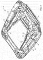
- FIG. 1 shows a schematic representation of a first exemplary embodiment of the roof structure according to the invention for an agricultural vehicle.
- the roof structure comprises a lower roof assembly 12 and an upper roof assembly 14.
- a climatic chamber 16 is formed in the lower roof assembly 12, wherein the upper roof assembly 14 can be fixed or detachably attached to the lower roof assembly 12 to enclose the climatic chamber 16.
- the roof structure 10 further comprises two inlet chambers 18 for non-conditioned air and two outlet chambers 20 for conditioned air, the inlet chambers 18 and the outlet chambers 20 being formed between the lower roof assembly 12 and the upper roof assembly 14 as separate chambers.
- Each inlet chamber comprises a fresh air opening (reference number 22, see Figure 2 ) for the supply of fresh air and a circulation opening (reference number 24, see Figure 2 ) for the supply of recirculated air.
- the roof structure 10 comprises an air guiding element 100 arranged in the inlet chambers 18.
- the air guiding element 100 is in this way at the fresh air openings (reference number 22, see FIG Figure 2 ) and at the circulation openings (Reference number 24, see Figure 2 ) and arranged on the climatic chamber 16 so that an area sealed off from an external environment is formed.
- the air guiding element 100 also has a cable duct 112 in which connecting lines, that is to say cables and / or hoses, are arranged.
- two second fans 28 and an air-conditioning assembly 30 are arranged in the climatic chamber 16, the second fan 28 having a second fan inlet and a second fan outlet.
- the second fan inlet can suck in air from the climatic chamber 16 and the second fan outlet can expel air into the outlet chamber 20.
- the air outlet (reference number 106, see Figures 3 and 4th ) of the air guiding element 100 is arranged on the air conditioning assembly 30, so that the filtered fresh air and the recirculated air can be guided directly onto the surface of the air conditioning assembly 30.
- Fig. 1 further shows a schematic representation of a first exemplary embodiment of the cabin 200 according to the invention for an agricultural vehicle comprising a roof structure 10.
- the cabin 200 comprises the above-described roof structure 10 and side walls 202, here four pieces, made of glass.
- the side walls 202 are attached to or releasably connected to the lower roof assembly 12.
- FIG. 2 shows a schematic representation of the lower roof assembly 12 of the roof structure 10 according to the invention
- the lower roof assembly shown essentially corresponds to that in FIG Figure 1 Lower roof assembly shown, so that only the differences are discussed below.
- the lower roof assembly comprises two inlet chambers 18, each with a fresh air opening 22 and a circulation opening 24.
- the fresh air and the recirculated air are connected to the second fan (reference numeral 28, Figure 1 ) can be sucked in, in the air guiding element (reference numeral 100, Figures 1 , 3 and 4th ) can be mixed and guided to the climatic chamber 16 in the sealed area.
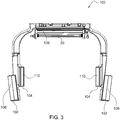
- FIG. 3 shows a schematic representation of the air guiding element 100 of the roof structure 10 according to the invention Figure 3
- the air guiding element 100 shown essentially corresponds to that in FIG Figure 1 Air guiding element 100 shown, which is why only the differences will be discussed below.
- the air guiding element 100 has two fresh air inlets 102 and two circulation inlets 104 and one air outlet 106.
- the fresh air opening (reference number 22, see Figure 2 ) with the fresh air inlet 102 and the circulation opening (reference number 24, see Figure 2 ) so connected to the circulation inlet 104 and the air outlet 106 to the climatic chamber (reference numeral 16, see FIG Figures 1 and 2 ) arranged that the fresh air and the recirculated air can be fed to the air guiding element, can be mixed in the air guiding element 100 and in the sealed area of the fresh air opening (reference number 22, see FIG Figure 2 ) and the circulation opening (reference number 24, see Figure 2 ) to the climatic chamber (reference number 16, see Figures 1 and 2 ) are feasible.
- a first filter element 108 is arranged on each of the fresh air inlets 102 and a second filter element 110 is arranged on each of the circulation inlets 104.
- Figure 4 shows a perspective view of the in Figure 3 shown air guide element 100 of the roof structure 10 according to the invention.
- FIG. 5 shows a perspective illustration of a further exemplary embodiment of a roof structure 10 according to the invention, in particular the lower roof group 12 with the filter arrangement 300 Figure 5
- the lower roof assembly 12 shown corresponds essentially to that in FIG Figures 1 and 2 Lower roof assembly 12 shown, so that only the differences will be discussed below.
- the filter arrangement 300 comprises a line 308, a first filter element 302, in particular with a filter, a holder 304 with a fastening element, a first fan 306 and a coupling element 310 Line 308 is connected to the coupling element 310, in particular attached to the coupling element 310, so that these are flow-connected.
- the coupling element 310 is detachably connected to or fastened to the fresh air inlet 22 of the lower roof assembly 12, but can also be permanently connected.
- FIG. 6 shows a perspective view of the coupling element 310.
- the coupling element 310 shown essentially corresponds to that in FIG Figure 5 coupling element 310 shown, so that only the differences will be discussed below.
- the coupling element 310 can be fastened to the lower roof assembly by means of a fastening element, here a coupling flange 316.
- the line 308 can be connected to the coupling element 310 via a connection piece 314.
Description
Die Erfindung betrifft eine Dachstruktur gemäss dem Oberbegriff des unabhängigen Anspruchs 1 und eine Kabine gemäss dem Oberbegriff des unabhängigen Anspruchs 10.The invention relates to a roof structure according to the preamble of independent claim 1 and a cabin according to the preamble of
Beim Einsatz eines landwirtschaftlichen Fahrzeugs, beispielsweise einer selbstfahrenden Feldspritze oder eines Traktors mit angehängtem oder angebauten Spritzgerät, kommen beim Spritzen auf dem Feld oftmals chemische Substanzen, insbesondere chemischer Pflanzenschutzmittel wie Pestizide, Herbizide oder Fungizide, zum Einsatz. Dadurch kann die Aussenumgebung, insbesondere auch die Umgebungsluft, mit Verschmutzungen belastet sein, beispielsweise mit Staub, Aerosolen und chemischen Dämpfen und Gasen, insbesondere auch den chemischen Substanzen. Um den Fahrer in der Kabine gegen derartige Verschmutzungen zu schützen, ist es bekannt, die Kabine mit einem Filterelement, beispielsweise einem Filter, zu versehen, welche die aus der Aussenumgebung angesaugte Luft filtert bzw. reinigt und die gefilterte Luft in das Innere der Kabine abgibt. Beispielsweise sieht die Norm EN 15695 zum Schutz des Fahrers von landwirtschaftlichen Fahrzeugen verschiedene Kategorien für Kabinen vor, sodass je nach Kabinenkategorie bestimmte Vorgaben erfüllt werden müssen. Eine Kabine der Kategorie 4 (CAT IV), welche eine Kabine mit hohen Anforderungen an die Luftreinheit beschreibt, muss beispielsweise derart ausgebildet sein, dass Verschmutzungen aus der Aussenumgebung nicht in das Innere der Kabine gelangen dürfen. Darüber hinaus werden landwirtschaftliche Fahrzeuge oft bei für den Fahrer unangenehmen warmen oder kalten Aussentemperaturen eingesetzt, sodass die Luft innerhalb der Kabine nicht nur gefiltert sondern auch klimatisiert werden muss. Aus diesem Grund ist die Kabine auch mit einer Klimaeinrichtung zur Klimatisierung der Luft im Inneren der Kabine versehen, beispielsweise einer Heizung und/oder einer Klimaanlagen-Baugruppe. Die Filtereinrichtung und/oder die Klimaeinrichtung können insbesondere in einer Dachstruktur angeordnet sein.When using an agricultural vehicle, for example a self-propelled field sprayer or a tractor with an attached or attached sprayer, chemical substances, in particular chemical pesticides such as pesticides, herbicides or fungicides, are often used when spraying in the field. As a result, the outside environment, in particular also the ambient air, can be contaminated with contamination, for example with dust, aerosols and chemical vapors and gases, in particular also chemical substances. In order to protect the driver in the cab against such contamination, it is known to provide the cab with a filter element, for example a filter, which filters or cleans the air sucked in from the outside environment and releases the filtered air into the interior of the cab . For example, the EN 15695 standard for the protection of the driver of agricultural vehicles provides different categories for cabs, so that specific requirements must be met depending on the cab category. A cabin of category 4 (CAT IV), which describes a cabin with high demands on air purity, must be designed, for example, in such a way that contamination from the outside environment must not get into the interior of the cabin. In addition, agricultural vehicles are often used in warm or cold outside temperatures that are uncomfortable for the driver, so that the air inside the cabin not only has to be filtered but also conditioned. For this reason, the cabin is also provided with an air conditioning device for air conditioning the air inside the cabin, for example a heater and / or an air conditioning assembly. The filter device and / or the air conditioning device can in particular be arranged in a roof structure.
Im Weiteren ist aus der
Ausgehend von diesem Stand der Technik ist es daher eine Aufgabe der vorliegenden Erfindung eine Dachstruktur und eine Kabine vorzuschlagen, welche die aus dem Stand der Technik bekannten Nachteile vermeidet, insbesondere eine Dachstruktur und eine Kabine vorzuschlagen, die das Eindringen von Verschmutzungen in den Innenraum der Dachstruktur und/oder das Innere der Kabine vermeidet und/oder konstruktiv einfach ausgestaltet und/oder eine zu Wartungszwecken vereinfachten Zugänglichkeit aufweist.Based on this prior art, it is therefore an object of the present invention to propose a roof structure and a cabin that avoids the disadvantages known from the prior art, in particular to propose a roof structure and a cabin that prevent dirt from penetrating into the interior of the roof structure and / or avoids the interior of the cabin and / or has a simple design and / or has simplified accessibility for maintenance purposes.
Diese Aufgabe wird durch eine Dachstruktur mit den Merkmalen des Anspruchs 1 und eine Kabine mit den Merkmalen des Anspruchs 10 gelöst.This object is achieved by a roof structure with the features of claim 1 and a cabin with the features of
Die abhängigen Ansprüche beziehen sich auf besonders vorteilhafte Ausführungsformen der Erfindung.The dependent claims relate to particularly advantageous embodiments of the invention.
Erfindungsgemäss wird eine Dachstruktur für ein landwirtschaftliches Fahrzeug vorgeschlagen, umfassend eine obere Dachbaugruppe und eine untere Dachbaugruppe, wobei in der unteren Dachbaugruppe eine Klimakammer ausgebildet ist. Die obere Dachbaugruppe ist hierbei zum Umschliessen der Klimakammer an der unteren Dachbaugruppe befestigbar. Im Weiteren umfasst die untere Dachbaugruppe eine Einlasskammer und eine Auslasskammer für klimatisierte Luft, wobei die Einlasskammer und die Auslasskammer zwischen der unteren Dachbaugruppe und der oberen Dachbaugruppe als voneinander getrennte Kammern ausgebildet sind. An der Einlasskammer ist ausserdem eine Zirkulationsöffnung zur Zufuhr von rezirkulierter Luft angeordnet. Die Dachstruktur umfasst ein in der Einlasskammer angeordnetes Luftführungselement, wobei das Luftführungselement derart an der Zirkulationsöffnung und an oder in der Klimakammer angeordnet ist, dass ein gegenüber einer Aussenumgebung abgedichteter Bereich ausgebildet ist.According to the invention, a roof structure for an agricultural vehicle is proposed, comprising an upper roof assembly and a lower roof assembly, a climatic chamber being formed in the lower roof assembly. The upper roof assembly can be attached to the lower roof assembly to enclose the climatic chamber. Furthermore, the lower roof assembly comprises an inlet chamber and an outlet chamber for conditioned air, the inlet chamber and the outlet chamber between the lower roof assembly and the upper roof assembly being designed as separate chambers. In addition, a circulation opening for the supply of recirculated air is arranged on the inlet chamber. The roof structure comprises an air guiding element arranged in the inlet chamber, the air guiding element being arranged at the circulation opening and on or in the climatic chamber in such a way that an area sealed off from an outside environment is formed.
Das landwirtschaftliche Fahrzeug kann eine landwirtschaftliche Zugmaschine oder Erntemaschine, im Speziellen ein Traktor oder Schlepper oder eine selbstfahrende Feldspritze oder dergleichen sein. Anstatt eines landwirtschaftlichen Fahrzeugs kann die Dachstruktur oder Kabine aber auch für eine Baumaschine sein, beispielsweise einen Bagger oder dergleichen. Das Luftführungselement ist zusätzlich in der Klimakammer angeordnet, also teilweise in der Einlasskammer und teilweise in der Klimakammer. Das Luftführungselement ist als ein geschlossener Kanal oder als ein röhrenförmiger Körper ausgebildet, insbesondere als Rohr. Ausserdem kann das Luftführungselement auch Kammern aufweisen, insbesondere Kammern, welche an die Form der Einlasskammer und/oder Auslasskammer angepasst sind. Die Form und/oder der Querschnitt des Luftführungselements können an die Geometrie der unteren Dachbaugruppe und/oder der oberen Dachbaugruppe, bevorzugt an die Geometrie der Einlasskammer und/oder der Klimakammer und/oder der Frischluftöffnung und der Zirkulationsöffnung angepasst sein. Unter einem abgedichteten Bereich kann im Folgenden ein Bereich innerhalb der Dachstruktur verstanden werden, der gegenüber der Aussenumgebung, also gegenüber Bereichen innerhalb und ausserhalb der Dachstruktur, abgedichtet ist und in welchen keine Verschmutzungen aus der Aussenumgebung eindringen können. Der abgedichtete Bereich wird also vom Luftführungselement selbst und dessen Anordnung in der Einlasskammer und an der Zirkulationsöffnung und in der Klimakammer ausgebildet.The agricultural vehicle can be an agricultural tractor or harvesting machine, in particular a tractor or tractor or a self-propelled field sprayer or the like. Instead of an agricultural vehicle, the roof structure or cabin can also be for a construction machine, for example an excavator or the like. The air guiding element is also arranged in the climatic chamber, that is to say partly in the inlet chamber and partly in the climatic chamber. The air guiding element is designed as a closed channel or as a tubular body, in particular as a tube. In addition, the air guiding element can also have chambers, in particular chambers which are adapted to the shape of the inlet chamber and / or outlet chamber. Form and / or the cross section of the air guiding element can be adapted to the geometry of the lower roof assembly and / or the upper roof assembly, preferably to the geometry of the inlet chamber and / or the climatic chamber and / or the fresh air opening and the circulation opening. In the following, a sealed area can be understood to mean an area within the roof structure which is sealed off from the outside environment, that is to say from areas inside and outside the roof structure, and into which no contamination from the outside environment can penetrate. The sealed area is thus formed by the air guiding element itself and its arrangement in the inlet chamber and on the circulation opening and in the climatic chamber.
Die untere Dachbaugruppe und/oder die obere Dachbaugruppe und/oder das Luftführungselement können aus einem Kunststoff und/oder aus einem Metall ausgebildet sein, bevorzugt aus einem Kompositematerial, besonders bevorzugt aus einem duroplastischen bzw. wärmeaushärtenden Kompositematerial.The lower roof assembly and / or the upper roof assembly and / or the air guiding element can be formed from a plastic and / or from a metal, preferably from a composite material, particularly preferably from a thermosetting or thermosetting composite material.
Das Luftführungselement kann aber auch aus einem Schaum aus Kunststoff sein. Der Schaum kann ein Schaum aus Kunststoff sein, bevorzugt expandierter Kunststoff, besonders bevorzugt expandiertes Polypropylen (EPP) oder expandiertes Polyethylen (EPE) oder expandiertes Polystyrol (EPS) oder expandiertes Polyethylenterephthalat (PET) oder ein expandiertes Biopolymer oder Polyurethanschaum (PUR) sein. Im Weiteren können die untere Dachbaugruppe und/oder die obere Dachbaugruppe und/oder das Luftführungselement ein Formteil und/oder ein rotationsgeformtes Teil und/oder ein blasgeformtes Teil aufweisen, oder aber ein Formteil und/oder ein rotationsgeformtes Teil und/oder ein blasgeformtes Teil sein. Ebenso können die untere Dachbaugruppe und/oder die obere Dachbaugruppe und/oder das Luftführungselement mittels eines Formpress- und/oder Rotoformverfahrens, beispielsweise Rotationssinterverfahren oder Rotationsschmelzverfahren oder Rotationsguss, und/oder Spritzblasformen, Doppelschicht Thermoformen oder 3D Druck hergestellt sein. Das Luftführungselement kann einstückig, also ein einteilige Bauteil sein, oder auch zweistückig, also ein zweiteilige Bauteil, oder ein mehrstückiges, also ein mehrteiliges Bauteil sein. Das zweistückige oder mehrstückige Luftführungselement kann miteinander verbunden, beispielsweise verschweisst oder verklebt oder mit einem Befestigungselement aneinander befestigt werden. An oder in der Auslasskammer kann eine Belüftungsöffnung für klimatisierte Luft angeordnet sein. Dabei kann die Belüftungsöffnung einen Luftschlitz oder ein Luftgitter aufweisen, mit welchem die Menge und die Richtung einer Luftströmung in die Kabine genaue und/oder bedarfsgerecht eingestellt werden kann.The air guiding element can, however, also be made of a plastic foam. The foam can be a plastic foam, preferably expanded plastic, particularly preferably expanded polypropylene (EPP) or expanded polyethylene (EPE) or expanded polystyrene (EPS) or expanded polyethylene terephthalate (PET) or an expanded biopolymer or polyurethane foam (PUR). Furthermore, the lower roof assembly and / or the upper roof assembly and / or the air guiding element can have a molded part and / or a rotationally molded part and / or a blow molded part, or else a molded part and / or a rotationally molded part and / or a blow molded part . Likewise, the lower roof assembly and / or the upper roof assembly and / or the air guiding element can be produced by means of a compression molding and / or rotoforming process, for example rotational sintering process or rotational melting process or rotational molding, and / or injection blow molding, double-layer thermoforming or 3D printing. The air guiding element can be in one piece, that is to say a one-piece component, or also in two pieces, that is to say a two-piece component, or a multi-piece, that is to say one be a multi-part component. The two-piece or multi-piece air guiding element can be connected to one another, for example welded or glued, or fastened to one another with a fastening element. A ventilation opening for conditioned air can be arranged on or in the outlet chamber. The ventilation opening can have an air slot or an air grille with which the amount and direction of an air flow into the cabin can be set precisely and / or as required.
Die obere Dachbaugruppe kann das gleiche periphere Profil wie die untere Dachbaugruppe umfassen, sodass die obere Dachbaugruppe komplementär an die untere Dachbaugruppe angepasst bzw. ausgeformt werden kann, um die Einlasskammer, Auslasskammer und Klimakammer zu umschließen und/oder abzudecken. Insbesondere können die Einlasskammer, die Auslasskammer und die Klimakammer als voneinander räumlich getrennte Kammern zwischen der unteren und oberen Dachbaugruppe ausgebildet sein. Das Luftführungselement wiederum kann einen abgedichteten Bereich zumindest in der Einlasskammer und/oder teilweise oder vollständig an bzw. in der Klimakammer ausbilden. Darüber hinaus kann die obere Dachbaugruppe entfernbare Zugangsverkleidung umfassen, beispielsweise in Form eines Blechs ausgebildet, um eine Wartung bzw. Instandsetzung der Komponenten der Klimaeinrichtung zu ermöglichen. Ausserdem kann eine Abdeckung an der Auslasskammer befestigbar sein, wodurch eine Isolierung der Auslasskammer gegenüber der oberen Dachbaugruppe erreicht wird. Die Dachstruktur kann auch eine weitere Einlasskammern und/oder eine weitere Auslasskammern umfassen, insbesondere eine erste und zweite Einlasskammer und/oder eine erste und zweite Auslasskammer. Die erste und zweite Einlasskammer sowie die erste und zweite Auslasskammer können diametral oder spiegelsymmetrisch zur Klimakammer angeordnet sein.The upper roof assembly can comprise the same peripheral profile as the lower roof assembly, so that the upper roof assembly can be complementarily adapted or shaped to the lower roof assembly in order to enclose and / or cover the inlet chamber, outlet chamber and climatic chamber. In particular, the inlet chamber, the outlet chamber and the climatic chamber can be designed as spatially separate chambers between the lower and upper roof assembly. The air guiding element, in turn, can form a sealed area at least in the inlet chamber and / or partially or completely on or in the climatic chamber. In addition, the upper roof assembly can comprise removable access paneling, for example in the form of a sheet metal, in order to enable maintenance or repair of the components of the air conditioning device. In addition, a cover can be fastened to the outlet chamber, as a result of which the outlet chamber is isolated from the upper roof assembly. The roof structure can also comprise a further inlet chamber and / or a further outlet chamber, in particular a first and second inlet chamber and / or a first and second outlet chamber. The first and second inlet chambers and the first and second outlet chambers can be arranged diametrically or mirror-symmetrically to the climatic chamber.
Unter Umständen kann es erforderlich sein in der Dachstruktur ein Dichtmittel oder ein Isolationsmaterial zwischen den oberen und unteren Dachbaugruppen vorzusehen. Die obere und untere Dachbaugruppe können ausserdem mit Befestigungsmitteln oder mit Klebemitteln aneinander befestigt sein. Zusätzlich kann an den äusseren Verbindungsstellen der unteren und oberen Dachbaugruppe eine Dichtung, insbesondere ein Dichtmittel oder Kitt, verwendet werden, um die zusammengesetzte Dachstruktur wasserdicht auszugestalten. Eine Schaumstoffdichtung bzw. -isolierung kann zum Abdichten zwischen den Dachbaugruppen und/oder zum Abdichten der optionalen Abdeckungen vorgesehen sein. Ebenso kann eine Schaumstoffdichtung in der Dachstruktur vorgesehen sein, um Luftbewegungen in Bereichen zu verhindern, in welchen Luft zu Isolationszwecken vorgesehen ist.Under certain circumstances it may be necessary to provide a sealant or insulation material in the roof structure between the upper and lower roof assemblies. The upper and lower roof assemblies can also be fastened to one another with fasteners or with adhesives. Additionally For example, a seal, in particular a sealant or putty, can be used at the outer connection points of the lower and upper roof assembly in order to make the assembled roof structure watertight. A foam seal or insulation can be provided for sealing between the roof assemblies and / or for sealing the optional covers. A foam seal can also be provided in the roof structure in order to prevent air movements in areas in which air is provided for insulation purposes.
Wesentlich für die Erfindung ist, dass aufgrund der Anordnung des Luftführungselements in der Dachstruktur und mittels des Luftführungselements selbst, in der Dachstruktur ein gegenüber der Aussenumgebung abgedichteter Bereich ausgebildet ist. In den abgedichteten Bereich gelangen keine Verschmutzungen aus der Aussenumgebung, insbesondere keine Verschmutzungen aus der Umgebungsluft. Aufgrund des abgedichteten Bereichs wird die über die Zirkulationsöffnung aus der Kabine zugeführte rezirkulierter Luft frei von Verschmutzungen aus der Aussenumgebung gehalten. Somit kann verhindert werden, dass Verschmutzungen an den äusseren Verbindungsstellen der unteren und oberen Dachbaugruppe, insbesondere wenn das Dichtmittel eine Leckage aufweist, in die Dachstruktur bzw. das Luftführungselement und in den Luftkreislauf, also den luftführenden Bereich, eindringen und somit über die Klimakammer und/oder Auslasskammer in die Kabine gelangen. Auf diese Weise wird gewährleistet, dass der Fahrer im Inneren der Kabine nicht direkt schädlichen Verschmutzungen ausgesetzt ist und die Gesundheit des Fahrers durch das Einatmen ungefilterter und mit schädlichen Verschmutzungen behafteter Umgebungsluft nicht gefährdet wird. Darüber hinaus wird aufgrund der einfachen konstruktiven Anordnung des Luftführungselements in der Dachstruktur und der einfachen Ausgestaltung der Dachstruktur weiterhin ein einfacher Zugang zu den in der Dachstruktur angeordneten und/oder anordenbaren Einrichtungen und Bauteilen gewährleistet. Somit können Wartungsarbeiten an der Dachstruktur auf einfache Art und Weise durchgeführt werden, und gleichzeitig die Kategorie 4 Anforderungen der EN 15695 erfüllt werden.It is essential for the invention that, due to the arrangement of the air guiding element in the roof structure and by means of the air guiding element itself, an area sealed off from the outside environment is formed in the roof structure. No contamination from the outside environment, in particular no contamination from the ambient air, gets into the sealed area. Due to the sealed area, the recirculated air supplied from the cabin via the circulation opening is kept free of contamination from the outside environment. It can thus be prevented that dirt at the outer connection points of the lower and upper roof assembly, especially if the sealant has a leak, penetrate into the roof structure or the air guiding element and into the air circuit, i.e. the air-guiding area, and thus via the climatic chamber and / or outlet chamber get into the cabin. This ensures that the driver is not directly exposed to harmful contamination inside the cab and that the driver's health is not endangered by breathing in unfiltered ambient air that is contaminated with harmful contamination. In addition, due to the simple structural arrangement of the air guiding element in the roof structure and the simple design of the roof structure, easy access to the devices and components that are arranged and / or can be arranged in the roof structure is ensured. Maintenance work on the roof structure can thus be carried out in a simple manner and at the same time the Category 4 requirements of EN 15695 are met.
Gemäß der Erfindung ist an, insbesondere in, der Einlasskammer und/oder an, insbesondere in, der Klimakammer eine Frischluftöffnung zur Zufuhr von Frischluft ausgebildet. Das Luftführungselement ist derart an der Frischluftöffnung und an der Zirkulationsöffnung und in, der Klimakammer angeordnet, dass ein gegenüber einer Außenumgebung abgedichteter Bereich ausgebildet ist. Die Einlasskammer kann also die Frischluftöffnung und die Zirkulationsöffnung umfassen, bevorzugt können die Frischluftöffnung und die Zirkulationsöffnung in der unteren Dachbaugruppe an oder in der Einlasskammer ausgebildet sein. Ebenso kann aber auch die Einlasskammer die Zirkulationsöffnung und die Klimakammer die Frischluftöffnung umfassen, bevorzugt kann die Zirkulationsöffnung in der unteren Dachbaugruppe an oder in der Einlasskammer und die Frischluftöffnung in der unteren Dachbaugruppe an oder in der Klimakammer ausgebildet sein. Die weitere Einlasskammer kann eine weitere Frischluftöffnung zur Zufuhr von Frischluft und eine weitere Zirkulationsöffnung zur Zufuhr von rezirkulierter Luft umfassen. Ebenso kann die Klimakammer eine weitere Frischluftöffnung zur Zufuhr von Frischluft umfassen. Die Zirkulationsöffnung kann benachbart und/oder gegenüber der Frischluftöffnung angeordnet sein. Der abgedichtete Bereich wird also vom Luftführungselement selbst und dessen Anordnung in der Einlasskammer, an der Frischluftöffnung und der Zirkulationsöffnung und an, insbesondere in, der Klimakammer ausgebildet. Aufgrund des abgedichteten Bereichs wird die über die Frischluftöffnung zugeführte Frischluft und die über die Zirkulationsöffnung aus der Kabine zugeführte rezirkulierter Luft frei von Verschmutzungen aus der Aussenumgebung gehalten. Somit kann vorteilhafterweise verhindert werden, dass Verschmutzungen in die Dachstruktur eindringen und in den Luftkreislauf und somit über die Klimakammer und/oder Auslasskammer in die Kabine gelangen.According to the invention, a fresh air opening for supplying fresh air is formed on, in particular in, the inlet chamber and / or on, in particular in, the climatic chamber. The air guiding element is arranged on the fresh air opening and on the circulation opening and in the climatic chamber in such a way that an area that is sealed off from an external environment is formed. The inlet chamber can thus comprise the fresh air opening and the circulation opening; the fresh air opening and the circulation opening can preferably be formed in the lower roof assembly on or in the inlet chamber. Likewise, however, the inlet chamber can also include the circulation opening and the climatic chamber the fresh air opening, preferably the circulation opening in the lower roof assembly can be formed on or in the inlet chamber and the fresh air opening in the lower roof assembly can be formed on or in the climatic chamber. The further inlet chamber can comprise a further fresh air opening for the supply of fresh air and a further circulation opening for the supply of recirculated air. The climatic chamber can also comprise a further fresh air opening for the supply of fresh air. The circulation opening can be arranged adjacent to and / or opposite the fresh air opening. The sealed area is thus formed by the air guiding element itself and its arrangement in the inlet chamber, on the fresh air opening and the circulation opening and on, in particular in, the climatic chamber. Due to the sealed area, the fresh air supplied via the fresh air opening and the recirculated air supplied from the cabin via the circulation opening are kept free of contamination from the outside environment. In this way, it can advantageously be prevented that dirt penetrates into the roof structure and gets into the air circuit and thus into the cabin via the climatic chamber and / or outlet chamber.
Gemäß der Erfindung weist das Luftführungselement einen Frischlufteinlass zur Zufuhr von Frischluft und einen Zirkulationseinlass zur Zufuhr von rezirkulierter Luft und einen Luftauslass zum Auslassen eines Gemischs aus Frischluft und rezirkulierter Luft auf. Dabei ist die Frischluftöffnung mit dem Frischlufteinlass und die Zirkulationsöffnung mit dem Zirkulationseinlass derart verbunden und der Luftauslass ist derart an der Klimakammer angeordnet, dass die Frischluft und die rezirkulierte Luft im Luftführungselement mischbar und das Gemisch aus Frischluft und rezirkulierter Luft im abgedichteten Bereich von der Frischluftöffnung und der Zirkulationsöffnung zum Luftauslass, insbesondere auch vom Luftauslass in die Klimakammer, führbar sind. Die Frischluftöffnung kann mit dem Frischlufteinlass und die Zirkulationsöffnung kann mit dem Zirkulationseinlass und diese beiden wiederum können mit dem Luftauslass und mit der Klimakammer kommunizierend in Verbindung stehen, also strömungsverbunden sein. Somit kann die Frischluft dem Luftführungselement über die Frischluftöffnung und den Frischlufteinlass und die rezirkulierte Luft über die Zirkulationsöffnung und den Zirkulationseinlass zugeführt werden. Im Luftführungselement sind die Frischluft und die rezirkulierte Luft mischbar und mittels des Luftauslasses der Klimakammer zuführbar. Der Luftauslass kann dabei an oder in der Klimakammer angeordnet sein. Das Luftführungselement kann einen, zwei oder mehrere Frischlufteinlässe und einen, zwei oder mehrere Zirkulationseinlässe aufweisen, insbesondere wenn die Dachstruktur zwei oder mehrere Einlasskammern mit je einer Frischluftöffnungen und einer Zirkulationsöffnungen umfasst. Ebenso kann die Dachstruktur zwei oder mehrere Luftauslässe umfassen, bevorzugt umfasst die Dachstruktur die gleiche Anzahl an Einlasskammern und Auslasskammern. Die zwei oder mehrere Einlasskammern und Auslasskammern können bevorzugt als voneinander räumlich getrennte Kammern zwischen der unteren und oberen Dachbaugruppe ausgebildet sein. Das Luftführungselement kann einen, zwei oder mehrere Frischlufteinlässe und/oder einen, zwei oder mehrere Zirkulationseinlässe aufweisen. Ebenso kann die Dachstruktur zwei oder mehrere Luftauslässe umfassen. Dabei können jeweils eine Frischluftöffnung mit einem Frischlufteinlass und jeweils eine Zirkulationsöffnung mit einem Zirkulationseinlass verbunden sein. Die Frischluftöffnungen und die Zirkulationsöffnungen können dabei über die Frischlufteinlässe und die Zirkulationseinlässen kommunizierend mit dem einen oder mehreren Luftauslässen in Verbindung stehen, also strömungsverbunden sein. Die Frischluftöffnung kann mit dem Frischlufteinlass und die Zirkulationsöffnung kann mit dem Zirkulationseinlass fest oder lösbar verbunden und/oder diese aneinander befestigt sein und/oder die Verbindungsstellen können abgedichtet sein.According to the invention, the air guiding element has a fresh air inlet for supplying fresh air and a circulation inlet for supplying recirculated air and an air outlet for discharging a mixture of fresh air and recirculated air. The fresh air opening with the fresh air inlet and the circulation opening with the circulation inlet are of this type and the air outlet is arranged on the climatic chamber in such a way that the fresh air and the recirculated air can be mixed in the air guiding element and the mixture of fresh air and recirculated air can be guided in the sealed area from the fresh air opening and the circulation opening to the air outlet, in particular also from the air outlet into the climatic chamber are. The fresh air opening can be connected to the fresh air inlet and the circulation opening can be connected to the circulation inlet and these two in turn can be in communication with the air outlet and with the climatic chamber, that is to say flow-connected. The fresh air can thus be supplied to the air guiding element via the fresh air opening and the fresh air inlet and the recirculated air via the circulation opening and the circulation inlet. The fresh air and the recirculated air can be mixed in the air guiding element and can be supplied to the climatic chamber by means of the air outlet. The air outlet can be arranged on or in the climatic chamber. The air guiding element can have one, two or more fresh air inlets and one, two or more circulation inlets, in particular if the roof structure comprises two or more inlet chambers, each with one fresh air opening and one circulation opening. The roof structure can likewise comprise two or more air outlets; the roof structure preferably comprises the same number of inlet chambers and outlet chambers. The two or more inlet chambers and outlet chambers can preferably be designed as chambers that are spatially separated from one another between the lower and upper roof assembly. The air guiding element can have one, two or more fresh air inlets and / or one, two or more circulation inlets. The roof structure can also comprise two or more air outlets. A fresh air opening can be connected to a fresh air inlet and a circulation opening can be connected to a circulation inlet. The fresh air openings and the circulation openings can be in communication with the one or more air outlets via the fresh air inlets and the circulation inlets, that is, they can be flow-connected. The fresh air opening can be connected to the fresh air inlet and the circulation opening can be fixedly or detachably connected to the circulation inlet and / or these can be fastened to one another and / or the connection points can be sealed.
Vorteilhafterweise kann somit verhindert werden, dass der Fahrer im Inneren der Kabine schädlichen Verschmutzungen direkt ausgesetzt ist und die Gesundheit des Fahrers durch das Einatmen ungefilterter und mit schädlichen Verschmutzungen behafteter Umgebungsluft nicht gefährdet wird.Advantageously, it can thus be prevented that the driver is directly exposed to harmful contamination in the interior of the cabin and that the driver's health is not endangered by breathing in unfiltered ambient air that is contaminated with harmful contamination.
In Ausgestaltung der Erfindung ist an der Frischluftöffnung und/oder am Frischlufteinlass eine Filteranordnung, insbesondere mit einem ersten Filterelement, angeordnet. Die Filteranordnung kann fest oder lösbar mit dem Frischlufteinlass oder der Frischluftöffnung verbunden bzw. gekoppelt sein oder aber an diesen befestigt sein. Die Filteranordnung kann eine Leitung und/oder ein erstes Filterelement und/oder eine Halterung mit einem Befestigungselement, um die Filteranordnung, insbesondere das erste Filterelement, zu halten und/oder zu befestigen, und/oder ein erstes Gebläse umfassen. Das erste Gebläse kann einen ersten Gebläseeinlass und einen ersten Gebläseauslass aufweisen. Der erste Gebläseeinlass kann Frischluft aus dem ersten Filterelement ansaugen und/oder der erste Gebläseauslass kann Luft in die Auslasskammer ausstossen. Das erste Filterelement kann zumindest einen Filter umfassen. In einem ersten Beispiel kann die Filteranordnung nur das erste Filterelement umfassen. In diesem Fall kann das erste Filterelement am Frischlufteinlass und/oder der Frischluftöffnung angeordnet sein, bevorzugt mit diesen verbunden bzw. gekoppelt oder an diesen befestigt sein. Die untere Dachbaugruppe kann dann einen ausgeformten Frischluftkanal umfassen, der vorzugsweise in der äußeren Peripherie der unteren Dachbaugruppe angeordnet sein, also der Fläche, die in Richtung der Kabine ausgerichtet ist. Der Frischluftkanal kann von einer entfernbaren Staubfangvorrichtung und/oder einem Einlassgitter umgeben bzw. abgedeckt sein. Die Frischluftöffnung kann ebenfalls an oder entlang der äußeren Peripherie der unteren Dachbaugruppe angeordnet sein, insbesondere auch vom Frischluftkanal umgeben sein. Das erste Filterelement kann entnehmbar an den Frischluftkanal angepasst sein. Somit kann Frischluft durch das Einlassgitter angesaugt werden und passiert das erste Filterelement bevor sie dem Luftführungselement zuführbar ist. In einem zweiten Beispiel kann die Filteranordnung zumindest die Leitung und das erste Filterelement und eine Halterung mit einem Befestigungselement und optional das erste Gebläse umfassen. In diesem Fall kann die Leitung lösbar mit dem Frischlufteinlass und/oder der Frischluftöffnung verbunden bzw. gekoppelt sein. Ausserdem kann das erste Filterelement ausserhalb der Dachstruktur, beispielsweise an einer Kabine angeordnet, insbesondere mittels des Halteelements an der Kabine fest oder lösbar befestigt oder mit dieser fest oder lösbar verbunden sein. Auf diese Weise wird gewähreistet, dass das erste Filterelement, insbesondere in den beiden Fällen, einfach gewechselt werden kann und unnötiger Wartungsaufwand vermieden wird. Vorteilhafterweise kann dadurch, insbesondere im zweiten Fall, die Frontfläche des ersten Filterelements und dadurch die Luftströmung in die Dachstruktur bzw. der Druck in der Kabine erhöht werden. Darüber hinaus können so vorteilhafterweise die Kategorie 4 Anforderungen mit nur einem Druckregler erfüllt werden. Ausserdem ist der Motor des Gebläses selbstkühlend und es kann auf weitere Gebläse, insbesondere in der Dachstruktur verzichtet werden, was den Geräuschpegel und die konstruktive Komplexität reduziert.In an embodiment of the invention, a filter arrangement, in particular with a first filter element, is arranged on the fresh air opening and / or on the fresh air inlet. The filter arrangement can be connected or coupled to the fresh air inlet or the fresh air opening in a fixed or detachable manner, or it can be fastened to these. The filter arrangement can comprise a line and / or a first filter element and / or a holder with a fastening element in order to hold and / or fasten the filter arrangement, in particular the first filter element, and / or a first fan. The first fan may have a first fan inlet and a first fan outlet. The first fan inlet can suck in fresh air from the first filter element and / or the first fan outlet can expel air into the outlet chamber. The first filter element can comprise at least one filter. In a first example, the filter arrangement can only comprise the first filter element. In this case, the first filter element can be arranged on the fresh air inlet and / or the fresh air opening, preferably connected or coupled to them or attached to them. The lower roof assembly can then comprise a shaped fresh air duct which is preferably arranged in the outer periphery of the lower roof assembly, that is to say the surface which is oriented in the direction of the cabin. The fresh air duct can be surrounded or covered by a removable dust collector and / or an inlet grille. The fresh air opening can also be arranged on or along the outer periphery of the lower roof assembly, in particular also be surrounded by the fresh air duct. The first filter element can be removably adapted to the fresh air duct. Fresh air can thus be sucked in through the inlet grille and passes the first filter element before it can be fed to the air guiding element. In a second example, the filter arrangement can include at least the line and the first filter element and a holder with a fastening element and optionally the first fan include. In this case, the line can be detachably connected or coupled to the fresh air inlet and / or the fresh air opening. In addition, the first filter element can be arranged outside the roof structure, for example on a cabin, in particular fixedly or releasably fastened to the cabin by means of the holding element or connected to it in a fixed or releasable manner. In this way it is guaranteed that the first filter element, in particular in both cases, can be changed easily and unnecessary maintenance expenditure is avoided. In this way, particularly in the second case, the front surface of the first filter element and thereby the air flow into the roof structure or the pressure in the cabin can advantageously be increased. In addition, category 4 requirements can advantageously be met with just one pressure regulator. In addition, the fan motor is self-cooling and further fans, especially in the roof structure, can be dispensed with, which reduces the noise level and the structural complexity.
In Ausgestaltung der Erfindung ist an der Zirkulationsöffnung und/oder am Zirkulationseinlass ein zweites Filterelement entfernbar angeordnet. Das zweite Filterelement kann zumindest einen Filter umfassen. Auf diese Weise wird gewähreistet, dass das zweite Filterelement einfach gewechselt werden kann und unnötiger Wartungsaufwand vermieden wird.In an embodiment of the invention, a second filter element is removably arranged on the circulation opening and / or on the circulation inlet. The second filter element can comprise at least one filter. This ensures that the second filter element can be changed easily and unnecessary maintenance is avoided.
In Ausgestaltung der Erfindung sind entweder die Filteranordnung, insbesondere die Leitung, und das Luftführungselement, insbesondere der Frischlufteinlass, oder die Filteranordnung, insbesondere die Leitung, und die Dachstruktur, insbesondere die Frischluftöffnung, mittels eines Kopplungselements verbunden. Die Filteranordnung kann also mittels des Kopplungselements fest oder lösbar mit dem Frischlufteinlass oder der Dachstruktur bzw. Frischluftöffnung verbunden oder an diesen befestigt sein. Das Kopplungselements ermöglicht es vorteilhafterweise, dass die Frischluft gleichmäßig in die Dachstruktur eingeführt werden kann. Dadurch kann die Rezirkulationszone, also der Bereich im Luftführungselement, in dem Frischluft und rezirkulierte Luft gemischt werden, auf ein Minimum reduziert werden, sodass der Druck in der Kabine vergrössert wird.In an embodiment of the invention, either the filter arrangement, in particular the line, and the air guiding element, in particular the fresh air inlet, or the filter arrangement, in particular the line, and the roof structure, in particular the fresh air opening, are connected by means of a coupling element. The filter arrangement can therefore be firmly or detachably connected to or attached to the fresh air inlet or the roof structure or fresh air opening by means of the coupling element. The coupling element advantageously enables the fresh air to be introduced uniformly into the roof structure. As a result, the recirculation zone, i.e. the area in the air guiding element in which fresh air and recirculated air are mixed, can be reduced to a minimum, so that the pressure in the cabin is increased.
In Ausgestaltung der Erfindung umfasst das Luftführungselement einen Kabelkanal. Vorteilhafterweise sind im Kabelkanal eine oder mehrere Verbindungsleitungen, insbesondere Leitungen für die Heizung oder den Wärmetauscher, also Elektro- und/oder Klimaleitungen bzw. -rohre, am Luftführungselement anordenbar, insbesondere von und/oder zu der Klimakammer, durch die Einlasskammer hin zu einer in der unteren Dachbaugruppe ausgebildeten Apertur. Diese Massnahme verhindert, dass Verbindungsleitungen im abgedichteten Bereich verlaufen und, beispielsweise bei einer Leckage der Verbindungsleitungen, Verschmutzungen in den abgedichteten Bereich gelangen. Darüber hinaus sind die Verbindungsleitungen im Kabelkanal einfach zugänglich und können somit einfach gewartet werden.In an embodiment of the invention, the air guiding element comprises a cable duct. One or more connecting lines, in particular lines for the heater or the heat exchanger, i.e. electrical and / or air conditioning lines or pipes, can advantageously be arranged on the air guide element in the cable duct, in particular from and / or to the climatic chamber, through the inlet chamber to an in the lower roof assembly formed aperture. This measure prevents connecting lines from running in the sealed area and, for example, in the event of a leak in the connecting lines, contamination from entering the sealed area. In addition, the connecting lines in the cable duct are easily accessible and can therefore be easily serviced.
In Ausgestaltung der Erfindung ist in der Dachstruktur in der Klimakammer und/oder in der Auslasskammer ein zweites Gebläse anordenbar oder angeordnet. Ebenso kann in der Klimakammer und/oder an der Auslasskammer eine Klimaanlagen-Baugruppe anordenbar oder angeordnet sein. Das zweite Gebläse weist dabei einen zweiten Gebläseeinlass und einen zweiten Gebläseauslass auf, wobei der zweite Gebläseeinlass Luft aus der Klimakammer ansaugt und/oder der zweite Gebläseauslass Luft in die Auslasskammer und/oder aus dem Luftführungselement ausstößt. Der Luftauslass kann an der Klimaanlagen-Baugruppe angeordnet sein. Der Luftauslass kann mit einem Klimaeinlass der Klimaanlagen-Baugruppe fest oder lösbar verbunden und/oder aneinander befestigt sein und/oder die Verbindungsstelle kann abgedichtet sein. Das zweite Gebläse kann entweder in der Klimakammer oder in der Auslasskammer, insbesondere in einer Gebläseaufnahme in der Klimakammer und/oder in der Auslasskammer angeordnet sein, welche zur Aufnahme und/oder zur Befestigung des zweiten Gebläses ausgebildet ist. Das zweite Gebläse kann auch teilweise in der Klimakammer und der Auslasskammer angeordnet sein, wobei dann die Gebläseaufnahme teilweise in der Klimakammer und der Auslasskammer angeordnet sein kann. Im Speziellen können in der Dachstruktur zwei zweite Gebläse vorgesehen und anordenbar bzw. angeordnet sein, insbesondere in jeweils einer Gebläseaufnahme anordenbar bzw. angeordnet sein. Die Klimaanlagen-Baugruppe kann derart am Luftführungselement angeordnet, insbesondere mit diesem fest oder lösbar verbunden und/oder an diesem befestigt sein, dass das Gemisch aus Frischluft und rezirkulierter Luft aus dem Luftführungselement in die Klimaanlagen-Baugruppe und aus der Klimaanlagen-Baugruppe in die Klimakammer oder Auslasskammer geführt werden kann und/oder strömen kann. Die Klimaanlagen-Baugruppe kann einen Wärmetauscher umfassen, insbesondere einen Verdampfer und/oder eine Heizungsbaugruppe und/oder eine Heizung umfassen, insbesondere Heizungs- und/oder Kühlelemente aufweisen, um sowohl eine Heizfunktion, als auch eine Kühlfunktion zur Verfügung zu stellen. Die Klimaanlagen-Baugruppe kann insbesondere an oder in der Klimakammer, welche zur Aufnahme und/oder zur Befestigung der Klimaanlagen-Baugruppe ausgebildet ist, und/oder an der Auslasskammer angeordnet sein. Vorteilhafterweise kann so ein Druckgradient in der Dachstruktur, insbesondere im Luftführungselement und/oder in der Klimakammer und/oder der Auslasskammer erzeugt werden. Darüber hinaus kann vorteilhafterweise das Gemisch aus Frischluft und rezirkulierter Luft aus dem abgedichteten Bereich direkt an die Klimaanlagen-Baugruppe geführt werden, insbesondere direkt an den Verdampfer und/oder die Heizung.In an embodiment of the invention, a second fan can be arranged or is arranged in the roof structure in the climatic chamber and / or in the outlet chamber. Likewise, an air conditioning assembly can be arranged or arranged in the climatic chamber and / or on the outlet chamber. The second fan has a second fan inlet and a second fan outlet, the second fan inlet drawing in air from the climatic chamber and / or the second fan outlet discharging air into the outlet chamber and / or out of the air guiding element. The air outlet can be arranged on the air conditioning assembly. The air outlet can be fixedly or detachably connected to an air conditioning inlet of the air conditioning assembly and / or attached to one another and / or the connection point can be sealed. The second fan can be arranged either in the climatic chamber or in the outlet chamber, in particular in a fan receptacle in the climatic chamber and / or in the outlet chamber, which is designed to accommodate and / or attach the second fan. The second fan can also be arranged partially in the climatic chamber and the outlet chamber, in which case the fan receptacle can be arranged partially in the climatic chamber and the outlet chamber. In particular, two second fans can be provided and arranged or arranged in the roof structure, in particular arranged or arranged in a respective fan receptacle be. The air conditioning assembly can be arranged on the air guide element, in particular permanently or detachably connected and / or attached to it, that the mixture of fresh air and recirculated air from the air guide element into the air conditioning assembly and from the air conditioning assembly into the climatic chamber or outlet chamber can be guided and / or can flow. The air conditioning assembly can include a heat exchanger, in particular an evaporator and / or a heating assembly and / or a heater, in particular have heating and / or cooling elements, in order to provide both a heating function and a cooling function. The air conditioning assembly can in particular be arranged on or in the climatic chamber, which is designed to accommodate and / or fasten the air conditioning assembly, and / or on the outlet chamber. In this way, a pressure gradient can advantageously be generated in the roof structure, in particular in the air guiding element and / or in the climatic chamber and / or the outlet chamber. In addition, the mixture of fresh air and recirculated air can advantageously be fed from the sealed area directly to the air conditioning assembly, in particular directly to the evaporator and / or the heater.
Die Erfindung betrifft ausserdem eine Kabine für ein landwirtschaftliches Fahrzeug, umfassend eine Dachstruktur, nach mindestens einem der Ansprüche 1 bis 9. Die erfindungsgemässe Kabine weist die oben beschriebenen Vorteile der erfindungsgemässen Dachstruktur auf.The invention also relates to a cabin for an agricultural vehicle, comprising a roof structure, according to at least one of claims 1 to 9. The cabin according to the invention has the advantages of the roof structure according to the invention described above.
In Ausgestaltung der Erfindung umfasst die Kabine mindestens eine Seitenwand und die Dachstruktur mit einer Filteranordnung. Die Filteranordnung kann eine Halterung mit einem Befestigungselement umfassen, und die Halterung kann die Filteranordnung, insbesondere das erste Filterelement, halten und/oder die Filteranordnung ist mittels des Befestigungselements an der Dachstruktur und/oder der Seitenwand befestigbar oder kann befestigt sein.In an embodiment of the invention, the cabin comprises at least one side wall and the roof structure with a filter arrangement. The filter arrangement can comprise a holder with a fastening element, and the holder can hold the filter arrangement, in particular the first filter element, and / or the filter arrangement can or can be fastened to the roof structure and / or the side wall by means of the fastening element.
Die Dachstruktur, insbesondere die zusammengesetzte Dachstruktur, kann als Dach der Kabine verwendet werden. Der Rest der Kabine kann von einem Boden und/oder einer oder mehreren Seitenwänden, im Speziellen auch einem Rahmen gebildet sein. Die Seitenwände können mit der Dachstruktur, bevorzugt mit der unteren Dachbaugruppe, besonders bevorzugt zwischen der Frischluftöffnung und der Zirkulationsöffnung, verbunden und/oder abgedichtet sein. Die Seitenwände können Metall-, Plastik- oder Glaselemente aufweisen, welche mit der Dachstruktur über herkömmliche Mittel verbunden sind.The roof structure, in particular the composite roof structure, can be used as the roof of the cabin. The rest of the cabin can be from a floor and / or one or more side walls, in particular also a frame. The side walls can be connected and / or sealed to the roof structure, preferably to the lower roof assembly, particularly preferably between the fresh air opening and the circulation opening. The side walls can comprise metal, plastic or glass elements which are connected to the roof structure by conventional means.
Insgesamt kann der Verlauf der Luftströmung in der Dachstruktur wie folgt beschrieben werden. Im Luftführungselement ist ein Druckgradient, insbesondere Über- und/oder Unterdruck, der vom ersten und/oder zweiten Gebläse erzeugt wird. Die Frischluft, die über die Filteranordnung durch die Frischluftöffnung oder Frischlufteinlass gefiltert in das Luftführungselement ansaugbar ist, und die rezirkulierte Luft, die insbesondere über das zweite Filterelement, durch die Zirkulationsöffnung gefiltert aus der Kabine in das Luftführungselement ansaugbar ist, kann im Luftführungselement gemischt und im abgedichteten Bereich in die Klimakammer geführt werden. Die gemischte Luft kann anschliessend die Klimaanlagen-Baugruppe passieren, wo sie entweder erwärmt oder gekühlt wird. Die klimatisierte Luft wird dann unter einer erhöhten Geschwindigkeit in die Auslasskammer ausgestossen, von wo aus die klimatisierte Luft über die Belüftungsöffnung in die Kabine geleitet wird.Overall, the course of the air flow in the roof structure can be described as follows. In the air guiding element there is a pressure gradient, in particular overpressure and / or underpressure, which is generated by the first and / or second fan. The fresh air, which is filtered through the fresh air opening or fresh air inlet and can be sucked into the air guiding element via the filter arrangement, and the recirculated air, which can be sucked into the air guiding element in particular via the second filter element through the circulation opening, can be mixed in the air guiding element and in the air guiding element sealed area into the climatic chamber. The mixed air can then pass through the air conditioning assembly, where it is either heated or cooled. The conditioned air is then expelled at an increased speed into the outlet chamber, from where the conditioned air is directed into the cabin via the ventilation opening.
Weitere vorteilhafte Massnahmen und bevorzugte Ausführungsbeispiele ergeben sich aus den abhängigen Ansprüchen.Further advantageous measures and preferred exemplary embodiments emerge from the dependent claims.
Im Folgenden wird die erfindungsgemäße Dachstruktur anhand von Ausführungsbeispielen unter Bezugnahme auf die Zeichnung näher erläutert. Dabei sind hinsichtlich ihrer Funktion übereinstimmende bzw. vergleichbare Bauteile mit denselben Bezugszeichen gekennzeichnet. In den schematischen Zeichnungen zeigen:
- Fig. 1
- eine perspektivische Ansicht eines ersten Ausführungsbeispiel der erfindungsgemässen Dachstruktur, und
- Fig. 2
- eine perspektivische Ansicht der unteren Dachbaugruppe der erfindungsgemässen Dachstruktur, und
- Fig. 3
- eine schematische Darstellung des Luftführungselements der erfindungsgemässen Dachstruktur, und
- Fig. 4
- eine perspektivische Ansicht des Luftführungselements der erfindungsgemässen Dachstruktur, und
- Fig. 5
- eine perspektivische Darstellung eines weiteren Ausführungsbeispiels einer erfindungsgemässen Dachstruktur, und
- Fig. 6
- eine perspektivische Ansicht des Kopplungselements.
- Fig. 1
- a perspective view of a first embodiment of the roof structure according to the invention, and
- Fig. 2
- a perspective view of the lower roof assembly of the roof structure according to the invention, and
- Fig. 3
- a schematic representation of the air guiding element of the roof structure according to the invention, and
- Fig. 4
- a perspective view of the air guiding element of the roof structure according to the invention, and
- Fig. 5
- a perspective illustration of a further embodiment of a roof structure according to the invention, and
- Fig. 6
- a perspective view of the coupling element.
In der Klimakammer 16 sind ausserdem zwei zweite Gebläse 28 und eine Klimaanlagen-Baugruppe 30 angeordnet, wobei das zweite Gebläse 28 einen zweite Gebläseeinlass und einen zweite Gebläseauslass aufweist. Der zweite Gebläseeinlass kann im Betriebszustand Luft aus der Klimakammer 16 ansaugen und der zweite Gebläseauslass Luft in die Auslasskammer 20 ausstossen. Der Luftauslass (Bezugszeichen 106, siehe
Claims (11)
- Roof structure for an agricultural vehicle, comprising
an upper roof assembly (14) and a lower roof assembly (12), wherein an air-conditioning chamber (16) is formed in the lower roof assembly (12), and the upper roof assembly (14) is able to be fastened to the lower roof assembly (12) in order to surround the air-conditioning chamber (16), and the roof structure (10) furthermore comprises an inlet chamber (18) and an outlet chamber (20) for air-conditioned air, wherein the inlet chamber (18) and the outlet chamber (20) are configured, between the lower roof assembly (12) and the upper roof assembly (14), as chambers that are separated from one another, and a circulation opening (24) for supplying recirculated air is arranged at the inlet chamber (18), wherein a fresh-air opening (22) for supplying fresh air is formed at the inlet chamber (18) and/or at the air-conditioning chamber (16),
characterized in that
the roof structure (10) comprises an air-guiding element (100) arranged in the inlet chamber (18) and in the air-conditioning chamber (16), wherein the air-guiding element (100) is configured as a closed duct or as a tubular body, and the air-guiding element (100) is arranged at the fresh-air opening (22) and at the circulation opening (24) and in the air-conditioning chamber (16) such that the air-guiding element itself forms a region in the inlet chamber (18) and in the air-conditioning chamber (16) that is sealed off from regions inside and outside the roof structure (10). - Roof structure according to Claim 1, characterized in that the air-guiding element (100) has a fresh-air inlet (102) for supplying fresh air and a circulation inlet (104) for supplying recirculated air and an air outlet (106) for letting out mixed air, and the fresh-air opening (22) is connected to the fresh-air inlet (102) and the circulation opening (24) is connected to the circulation outlet (104), and the air outlet (106) is arranged at the air-conditioning chamber (16), such that the fresh air and the recirculated air are able to be mixed in the air-guiding element (100) and are able to be guided in the sealed-off region from the fresh-air opening (22) and the circulation opening (24) to the air outlet (106).
- Roof structure according to at least one of the preceding claims, characterized in that a filter arrangement (300), in particular having a first filter element (108), is arranged at the fresh-air opening (22) and/or at the fresh-air inlet (102).
- Roof structure according to at least one of the preceding claims, characterized in that a second filter element (110) is arranged in a removable manner at the circulation opening (24) and/or at the circulation inlet (104).
- Roof structure according to at least one of the preceding claims, characterized in that the filter arrangement (300) and the air-guiding element (100) or the filter arrangement (300) and the roof structure (10) are connected by means of a coupling element (310).
- Roof structure according to at least one of the preceding claims, characterized in that the air-guiding element (100) comprises a cable duct (112).
- Roof structure according to at least one of the preceding claims, characterized in that a second fan (28) is arrangeable in the air-conditioning chamber (16) and/or in the outlet chamber (20), and/or an air-conditioning system assembly (30) is arrangeable in the air-conditioning chamber (16) and/or at the outlet chamber (20).
- Roof structure according to Claim 7, characterized in that the second fan (28) has a fan inlet and a fan outlet, wherein the fan inlet sucks up air from the air-conditioning chamber (16) and/or the fan outlet discharges air into the outlet chamber (20).
- Roof structure according to Claim 7 or 8, characterized in that the air outlet (106) is arranged at the air-conditioning system assembly (30) .
- Cab for an agricultural vehicle, comprising a roof structure according to at least one of Claims 1 to 9.
- Cab according to Claim 10, characterized in that the cab (200) comprises at least one side wall (202) and the roof structure (10) having a filter arrangement (300) .
Priority Applications (2)
| Application Number | Priority Date | Filing Date | Title |
|---|---|---|---|
| US16/386,673 US11660931B2 (en) | 2018-04-20 | 2019-04-17 | Roof structure and cab |
| US16/386,649 US11590824B2 (en) | 2018-04-20 | 2019-04-17 | Roof structure and cab |
Applications Claiming Priority (1)
| Application Number | Priority Date | Filing Date | Title |
|---|---|---|---|
| DE102018206111.4A DE102018206111A1 (en) | 2018-04-20 | 2018-04-20 | roof structure |
Publications (2)
| Publication Number | Publication Date |
|---|---|
| EP3556585A1 EP3556585A1 (en) | 2019-10-23 |
| EP3556585B1 true EP3556585B1 (en) | 2021-03-31 |
Family
ID=66217811
Family Applications (2)
| Application Number | Title | Priority Date | Filing Date |
|---|---|---|---|
| EP19169597.2A Active EP3556585B1 (en) | 2018-04-20 | 2019-04-16 | Roof structure and cabin |
| EP19169603.8A Active EP3556586B1 (en) | 2018-04-20 | 2019-04-16 | Roof structure and cabin |
Family Applications After (1)
| Application Number | Title | Priority Date | Filing Date |
|---|---|---|---|
| EP19169603.8A Active EP3556586B1 (en) | 2018-04-20 | 2019-04-16 | Roof structure and cabin |
Country Status (3)
| Country | Link |
|---|---|
| US (2) | US11660931B2 (en) |
| EP (2) | EP3556585B1 (en) |
| DE (1) | DE102018206111A1 (en) |
Families Citing this family (2)
| Publication number | Priority date | Publication date | Assignee | Title |
|---|---|---|---|---|
| EP3517413B1 (en) * | 2018-01-25 | 2020-07-08 | Kubota Corporation | Cabin-protection structure and tractor |
| GB201917952D0 (en) | 2019-12-09 | 2020-01-22 | Agco Int Gmbh | Air treatment apparatus |
Family Cites Families (49)
| Publication number | Priority date | Publication date | Assignee | Title |
|---|---|---|---|---|
| US4097085A (en) * | 1976-08-10 | 1978-06-27 | Harmon's Northern Mfg., Inc. | Tractor |
| US4072487A (en) * | 1976-12-10 | 1978-02-07 | Steiger Tractor Inc. | Air conditioning apparatus for tractor cab |
| US4189987A (en) | 1978-07-03 | 1980-02-26 | International Harvester Company | Vehicle cab temperature control system |
| US4641502A (en) * | 1985-01-09 | 1987-02-10 | The Duo-Therm Corporation | Roof mount air conditioner |
| DE4002754C2 (en) | 1990-01-31 | 1994-03-17 | Daimler Benz Ag | Filter arrangement used in the supply air flow of a heating or air conditioning system of a motor vehicle |
| US5310239A (en) | 1993-02-22 | 1994-05-10 | Paccar Inc | Modular cab and sleeper structural assembly for a truck-tractor vehicle |
| US5484221A (en) * | 1994-03-07 | 1996-01-16 | Rockwell International Corp. | Panel mounting system |
| GB2299060A (en) * | 1995-03-18 | 1996-09-25 | Ford New Holland Ltd | One-piece tractor roof with built-in heating and ventilation/air conditioning |
| US5913566A (en) * | 1996-11-12 | 1999-06-22 | New Holland North America, Inc. | Combine cab roof |
| US6178612B1 (en) * | 1998-10-08 | 2001-01-30 | Trp, Inc. | Method of converting a truck sleeper cab to a day cab |
| JP3579279B2 (en) * | 1999-01-28 | 2004-10-20 | 株式会社クボタ | cabin |
| US6223807B1 (en) * | 1999-07-09 | 2001-05-01 | Clark Equipment Company | Heating, ventilating and air conditioning system for a skid steer loader |
| US6279978B1 (en) | 1999-10-05 | 2001-08-28 | Deere & Company | Work vehicle roof structure |
| US6398294B1 (en) * | 2000-06-06 | 2002-06-04 | Deere & Company | Easy access HVAC module on work vehicle |
| DE10118344A1 (en) * | 2001-04-12 | 2002-10-17 | Daimler Chrysler Ag | Modular cab series for trucks |
| US6768423B2 (en) * | 2002-02-21 | 2004-07-27 | Case Corporation | Cab environment warning and control method and apparatus |
| JP3976246B2 (en) * | 2002-05-14 | 2007-09-12 | 新キャタピラー三菱株式会社 | Air conditioner in construction machinery |
| US6719361B1 (en) * | 2002-10-29 | 2004-04-13 | Mack Trucks, Inc. | Truck sleeper cab to day cab conversion kit assembly |
| US6780097B2 (en) | 2003-01-29 | 2004-08-24 | Deere & Company | Two piece vehicle roof structure having an integrated HVAC system |
| US6883860B1 (en) | 2003-12-02 | 2005-04-26 | East Side Heavy Truck Collision | Kit and method for truck cab conversion |
| US8033899B2 (en) * | 2005-08-31 | 2011-10-11 | Kubota Corporation | Cabin for a work vehicle |
| DE602005007754D1 (en) * | 2005-11-16 | 2008-08-07 | Denso Thermal Systems Spa | Roof of a cab, especially for an agricultural machine |
| US20070205633A1 (en) * | 2006-03-01 | 2007-09-06 | Waco Douglas L | Roof system with integrated hvac ducting |
| US7334834B2 (en) * | 2006-03-09 | 2008-02-26 | Deere & Company | Tractor cab roof with integral HVAC air ducts |
| US8568209B2 (en) | 2006-06-23 | 2013-10-29 | Dometic Corporation | Vehicle air-conditioning systems |
| US7338357B2 (en) * | 2006-07-12 | 2008-03-04 | Cnh America Llc | Filter purge control for HVAC fixed air circulation system |
| US7726142B2 (en) | 2006-09-08 | 2010-06-01 | Deere & Company | Low profile HVAC system |
| JP4618347B2 (en) * | 2008-08-08 | 2011-01-26 | 株式会社デンソー | Air conditioner for vehicles |
| US20150140917A9 (en) | 2008-10-09 | 2015-05-21 | Paul Thomas Bruss | Sealed duct cab post |
| GB2466766A (en) | 2008-10-27 | 2010-07-07 | Agco Gmbh | Tractor cab with cavity floor for HVAC unit and ducting |
| GB0822586D0 (en) | 2008-12-11 | 2009-01-14 | Agco Gmbh | Tractor cab heating and ventilating systems |
| US8403734B2 (en) | 2009-02-20 | 2013-03-26 | Deere & Company | Vent control system |
| IT1401209B1 (en) * | 2010-07-02 | 2013-07-12 | Cnh Italia Spa | CABIN FOR AGRICULTURAL VEHICLE EQUIPPED WITH A VENTILATION AND AIR-CONDITIONING SYSTEM |
| JP5482720B2 (en) | 2011-04-19 | 2014-05-07 | 株式会社デンソー | Air conditioner for vehicles |
| JP5843470B2 (en) | 2011-04-26 | 2016-01-13 | 三菱重工業株式会社 | Manned vehicle and cabin structure of the vehicle |
| AU2012297559B2 (en) | 2011-08-18 | 2013-12-19 | Knowles, Greg Brian Mr | Air contaminant filtration system for a cabin |
| JP5684768B2 (en) | 2012-09-27 | 2015-03-18 | 株式会社クボタ | Work vehicle |
| ITTO20130418A1 (en) | 2013-05-24 | 2014-11-25 | Denso Thermal Systems Spa | AIR FILTRATION SYSTEM IN CABIN FOR AGRICULTURAL MACHINES |
| EP3166810B1 (en) | 2014-07-09 | 2018-08-29 | CNH Industrial Italia S.p.A. | Selective filtration level air treatment system. |
| JP2016030559A (en) * | 2014-07-30 | 2016-03-07 | ヤンマー株式会社 | Work vehicle |
| CN105413321A (en) | 2014-09-12 | 2016-03-23 | 曼·胡默尔有限公司 | Filter Element for a Filter Device for Gas Filtration |
| US9821629B2 (en) | 2015-06-23 | 2017-11-21 | Deere & Company | Operator station |
| US9902233B2 (en) | 2015-06-23 | 2018-02-27 | Deere & Company | Roof for a work vehicle |
| DE102015211605A1 (en) | 2015-06-23 | 2016-12-29 | Mahle International Gmbh | Condenser unit of a rooftop air conditioning system |
| DE102016201648A1 (en) | 2016-02-03 | 2017-08-03 | Mahle International Gmbh | filtering device |
| US10150348B2 (en) | 2016-12-27 | 2018-12-11 | Cnh Industrial America Llc | Airflow control system of a work vehicle |
| IT201700051396A1 (en) | 2017-05-11 | 2018-11-11 | Cnh Ind Italia Spa | REGENERATION FILTER FOR CLEAN AIR IN AN AIR-CONDITIONING SYSTEM FOR A WORKING VEHICLE |
| DE102017115126A1 (en) | 2017-07-06 | 2019-01-10 | Claas Selbstfahrende Erntemaschinen Gmbh | Cabin for an agricultural work vehicle |
| EP3636467B1 (en) | 2018-10-10 | 2023-02-22 | Kubota Corporation | Working vehicle |
-
2018
- 2018-04-20 DE DE102018206111.4A patent/DE102018206111A1/en not_active Withdrawn
-
2019
- 2019-04-16 EP EP19169597.2A patent/EP3556585B1/en active Active
- 2019-04-16 EP EP19169603.8A patent/EP3556586B1/en active Active
- 2019-04-17 US US16/386,673 patent/US11660931B2/en active Active
- 2019-04-17 US US16/386,649 patent/US11590824B2/en active Active
Non-Patent Citations (1)
| Title |
|---|
| None * |
Also Published As
| Publication number | Publication date |
|---|---|
| EP3556585A1 (en) | 2019-10-23 |
| EP3556586B1 (en) | 2021-04-07 |
| US11590824B2 (en) | 2023-02-28 |
| DE102018206111A1 (en) | 2019-10-24 |
| US11660931B2 (en) | 2023-05-30 |
| EP3556586A1 (en) | 2019-10-23 |
| US20190322322A1 (en) | 2019-10-24 |
| US20190322156A1 (en) | 2019-10-24 |
Similar Documents
| Publication | Publication Date | Title |
|---|---|---|
| DE19628089C2 (en) | Ventilation device for a vehicle cabin and filter housing | |
| EP0438076B1 (en) | Air distributing arrangement for vehicle cabins | |
| DE10037384B4 (en) | Heating and air conditioning for a motor vehicle | |
| DE10046935B4 (en) | Heating and possibly air conditioning unit for commercial vehicles, e.g. B. Buses | |
| EP0200899B1 (en) | Apparatus for ventilating and air conditioning driver's areas, driver's cabs or the like | |
| DE102004004197A1 (en) | Two-part roof structure | |
| EP3556585B1 (en) | Roof structure and cabin | |
| DE102014201675B4 (en) | FASTENING ARRANGEMENT FOR AN ELECTRICAL ASSEMBLY OF A VEHICLE | |
| EP2921327B1 (en) | Driver cabin of a working machine usable in agriculture or civil engineering | |
| DE112019002360T5 (en) | Blower | |
| AT393817B (en) | BONNET, ESPECIALLY FOR A COMMERCIAL VEHICLE | |
| WO2011036055A2 (en) | Air-conditioning system | |
| EP2218598B1 (en) | Vehicle air conditioning system | |
| DE19515836B4 (en) | Heating and ventilation device for interiors of vehicles | |
| WO2015058937A1 (en) | Motor vehicle with an additional cooling system | |
| EP3424805A1 (en) | Cabin for an agricultural working device | |
| EP0786363A2 (en) | Air duct arrangement for the aeration or heatingof the rear passenger compartiment of a vehicle | |
| DE2843746A1 (en) | Public transport vehicle heating and ventilating equipment - has housing formed by one-piece bowl of synthetic material | |
| DE10315379A1 (en) | Stem of a motor vehicle | |
| EP0306755B1 (en) | Device for heating, ventilating and/or air conditioning motor vehicles | |
| DE102018113902B4 (en) | Device for a ventilation system | |
| DE1755898B2 (en) | PASSENGER VEHICLE WITH AIR HEATING | |
| DE19909663A1 (en) | Motor vehicle heating or air-conditioning installation comprises an air distribution module which is constituted as a part of an instrument panel | |
| EP3424760A1 (en) | Cabin for an agricultural working device | |
| EP2072295B1 (en) | Air duct housing for a vehicle |
Legal Events
| Date | Code | Title | Description |
|---|---|---|---|
| PUAI | Public reference made under article 153(3) epc to a published international application that has entered the european phase |
Free format text: ORIGINAL CODE: 0009012 |
|
| STAA | Information on the status of an ep patent application or granted ep patent |
Free format text: STATUS: THE APPLICATION HAS BEEN PUBLISHED |
|
| AK | Designated contracting states |
Kind code of ref document: A1 Designated state(s): AL AT BE BG CH CY CZ DE DK EE ES FI FR GB GR HR HU IE IS IT LI LT LU LV MC MK MT NL NO PL PT RO RS SE SI SK SM TR |
|
| AX | Request for extension of the european patent |
Extension state: BA ME |
|
| STAA | Information on the status of an ep patent application or granted ep patent |
Free format text: STATUS: REQUEST FOR EXAMINATION WAS MADE |
|
| 17P | Request for examination filed |
Effective date: 20200423 |
|
| RBV | Designated contracting states (corrected) |
Designated state(s): AL AT BE BG CH CY CZ DE DK EE ES FI FR GB GR HR HU IE IS IT LI LT LU LV MC MK MT NL NO PL PT RO RS SE SI SK SM TR |
|
| GRAP | Despatch of communication of intention to grant a patent |
Free format text: ORIGINAL CODE: EPIDOSNIGR1 |
|
| STAA | Information on the status of an ep patent application or granted ep patent |
Free format text: STATUS: GRANT OF PATENT IS INTENDED |
|
| INTG | Intention to grant announced |
Effective date: 20201210 |
|
| GRAS | Grant fee paid |
Free format text: ORIGINAL CODE: EPIDOSNIGR3 |
|
| GRAA | (expected) grant |
Free format text: ORIGINAL CODE: 0009210 |
|
| STAA | Information on the status of an ep patent application or granted ep patent |
Free format text: STATUS: THE PATENT HAS BEEN GRANTED |
|
| AK | Designated contracting states |
Kind code of ref document: B1 Designated state(s): AL AT BE BG CH CY CZ DE DK EE ES FI FR GB GR HR HU IE IS IT LI LT LU LV MC MK MT NL NO PL PT RO RS SE SI SK SM TR |
|
| REG | Reference to a national code |
Ref country code: GB Ref legal event code: FG4D Free format text: NOT ENGLISH Ref country code: CH Ref legal event code: EP |
|
| REG | Reference to a national code |
Ref country code: AT Ref legal event code: REF Ref document number: 1376535 Country of ref document: AT Kind code of ref document: T Effective date: 20210415 |
|
| REG | Reference to a national code |
Ref country code: IE Ref legal event code: FG4D Free format text: LANGUAGE OF EP DOCUMENT: GERMAN |
|
| REG | Reference to a national code |
Ref country code: DE Ref legal event code: R096 Ref document number: 502019001083 Country of ref document: DE |
|
| REG | Reference to a national code |
Ref country code: NL Ref legal event code: FP |
|
| REG | Reference to a national code |
Ref country code: LT Ref legal event code: MG9D |
|
| PG25 | Lapsed in a contracting state [announced via postgrant information from national office to epo] |
Ref country code: BG Free format text: LAPSE BECAUSE OF FAILURE TO SUBMIT A TRANSLATION OF THE DESCRIPTION OR TO PAY THE FEE WITHIN THE PRESCRIBED TIME-LIMIT Effective date: 20210630 Ref country code: FI Free format text: LAPSE BECAUSE OF FAILURE TO SUBMIT A TRANSLATION OF THE DESCRIPTION OR TO PAY THE FEE WITHIN THE PRESCRIBED TIME-LIMIT Effective date: 20210331 Ref country code: HR Free format text: LAPSE BECAUSE OF FAILURE TO SUBMIT A TRANSLATION OF THE DESCRIPTION OR TO PAY THE FEE WITHIN THE PRESCRIBED TIME-LIMIT Effective date: 20210331 Ref country code: NO Free format text: LAPSE BECAUSE OF FAILURE TO SUBMIT A TRANSLATION OF THE DESCRIPTION OR TO PAY THE FEE WITHIN THE PRESCRIBED TIME-LIMIT Effective date: 20210630 |
|
| PG25 | Lapsed in a contracting state [announced via postgrant information from national office to epo] |
Ref country code: LV Free format text: LAPSE BECAUSE OF FAILURE TO SUBMIT A TRANSLATION OF THE DESCRIPTION OR TO PAY THE FEE WITHIN THE PRESCRIBED TIME-LIMIT Effective date: 20210331 Ref country code: RS Free format text: LAPSE BECAUSE OF FAILURE TO SUBMIT A TRANSLATION OF THE DESCRIPTION OR TO PAY THE FEE WITHIN THE PRESCRIBED TIME-LIMIT Effective date: 20210331 Ref country code: SE Free format text: LAPSE BECAUSE OF FAILURE TO SUBMIT A TRANSLATION OF THE DESCRIPTION OR TO PAY THE FEE WITHIN THE PRESCRIBED TIME-LIMIT Effective date: 20210331 |
|
| PG25 | Lapsed in a contracting state [announced via postgrant information from national office to epo] |
Ref country code: SM Free format text: LAPSE BECAUSE OF FAILURE TO SUBMIT A TRANSLATION OF THE DESCRIPTION OR TO PAY THE FEE WITHIN THE PRESCRIBED TIME-LIMIT Effective date: 20210331 Ref country code: LT Free format text: LAPSE BECAUSE OF FAILURE TO SUBMIT A TRANSLATION OF THE DESCRIPTION OR TO PAY THE FEE WITHIN THE PRESCRIBED TIME-LIMIT Effective date: 20210331 Ref country code: EE Free format text: LAPSE BECAUSE OF FAILURE TO SUBMIT A TRANSLATION OF THE DESCRIPTION OR TO PAY THE FEE WITHIN THE PRESCRIBED TIME-LIMIT Effective date: 20210331 Ref country code: CZ Free format text: LAPSE BECAUSE OF FAILURE TO SUBMIT A TRANSLATION OF THE DESCRIPTION OR TO PAY THE FEE WITHIN THE PRESCRIBED TIME-LIMIT Effective date: 20210331 |
|
| PG25 | Lapsed in a contracting state [announced via postgrant information from national office to epo] |
Ref country code: IS Free format text: LAPSE BECAUSE OF FAILURE TO SUBMIT A TRANSLATION OF THE DESCRIPTION OR TO PAY THE FEE WITHIN THE PRESCRIBED TIME-LIMIT Effective date: 20210731 Ref country code: PL Free format text: LAPSE BECAUSE OF FAILURE TO SUBMIT A TRANSLATION OF THE DESCRIPTION OR TO PAY THE FEE WITHIN THE PRESCRIBED TIME-LIMIT Effective date: 20210331 Ref country code: SK Free format text: LAPSE BECAUSE OF FAILURE TO SUBMIT A TRANSLATION OF THE DESCRIPTION OR TO PAY THE FEE WITHIN THE PRESCRIBED TIME-LIMIT Effective date: 20210331 Ref country code: PT Free format text: LAPSE BECAUSE OF FAILURE TO SUBMIT A TRANSLATION OF THE DESCRIPTION OR TO PAY THE FEE WITHIN THE PRESCRIBED TIME-LIMIT Effective date: 20210802 Ref country code: RO Free format text: LAPSE BECAUSE OF FAILURE TO SUBMIT A TRANSLATION OF THE DESCRIPTION OR TO PAY THE FEE WITHIN THE PRESCRIBED TIME-LIMIT Effective date: 20210331 |
|
| PG25 | Lapsed in a contracting state [announced via postgrant information from national office to epo] |
Ref country code: LU Free format text: LAPSE BECAUSE OF NON-PAYMENT OF DUE FEES Effective date: 20210416 |
|
| REG | Reference to a national code |
Ref country code: DE Ref legal event code: R097 Ref document number: 502019001083 Country of ref document: DE |
|
| REG | Reference to a national code |
Ref country code: BE Ref legal event code: MM Effective date: 20210430 |
|
| PG25 | Lapsed in a contracting state [announced via postgrant information from national office to epo] |
Ref country code: MC Free format text: LAPSE BECAUSE OF FAILURE TO SUBMIT A TRANSLATION OF THE DESCRIPTION OR TO PAY THE FEE WITHIN THE PRESCRIBED TIME-LIMIT Effective date: 20210331 Ref country code: DK Free format text: LAPSE BECAUSE OF FAILURE TO SUBMIT A TRANSLATION OF THE DESCRIPTION OR TO PAY THE FEE WITHIN THE PRESCRIBED TIME-LIMIT Effective date: 20210331 Ref country code: AL Free format text: LAPSE BECAUSE OF FAILURE TO SUBMIT A TRANSLATION OF THE DESCRIPTION OR TO PAY THE FEE WITHIN THE PRESCRIBED TIME-LIMIT Effective date: 20210331 Ref country code: ES Free format text: LAPSE BECAUSE OF FAILURE TO SUBMIT A TRANSLATION OF THE DESCRIPTION OR TO PAY THE FEE WITHIN THE PRESCRIBED TIME-LIMIT Effective date: 20210331 |
|
| PLBE | No opposition filed within time limit |
Free format text: ORIGINAL CODE: 0009261 |
|
| STAA | Information on the status of an ep patent application or granted ep patent |
Free format text: STATUS: NO OPPOSITION FILED WITHIN TIME LIMIT |
|
| 26N | No opposition filed |
Effective date: 20220104 |
|
| PG25 | Lapsed in a contracting state [announced via postgrant information from national office to epo] |
Ref country code: IE Free format text: LAPSE BECAUSE OF NON-PAYMENT OF DUE FEES Effective date: 20210416 |
|
| PG25 | Lapsed in a contracting state [announced via postgrant information from national office to epo] |
Ref country code: IS Free format text: LAPSE BECAUSE OF FAILURE TO SUBMIT A TRANSLATION OF THE DESCRIPTION OR TO PAY THE FEE WITHIN THE PRESCRIBED TIME-LIMIT Effective date: 20210731 |
|
| PG25 | Lapsed in a contracting state [announced via postgrant information from national office to epo] |
Ref country code: BE Free format text: LAPSE BECAUSE OF NON-PAYMENT OF DUE FEES Effective date: 20210430 |
|
| REG | Reference to a national code |
Ref country code: CH Ref legal event code: PL |
|
| PG25 | Lapsed in a contracting state [announced via postgrant information from national office to epo] |
Ref country code: LI Free format text: LAPSE BECAUSE OF NON-PAYMENT OF DUE FEES Effective date: 20220430 Ref country code: CH Free format text: LAPSE BECAUSE OF NON-PAYMENT OF DUE FEES Effective date: 20220430 |
|
| PG25 | Lapsed in a contracting state [announced via postgrant information from national office to epo] |
Ref country code: CY Free format text: LAPSE BECAUSE OF FAILURE TO SUBMIT A TRANSLATION OF THE DESCRIPTION OR TO PAY THE FEE WITHIN THE PRESCRIBED TIME-LIMIT Effective date: 20210331 |
|
| PGFP | Annual fee paid to national office [announced via postgrant information from national office to epo] |
Ref country code: NL Payment date: 20230426 Year of fee payment: 5 |
|
| PG25 | Lapsed in a contracting state [announced via postgrant information from national office to epo] |
Ref country code: HU Free format text: LAPSE BECAUSE OF FAILURE TO SUBMIT A TRANSLATION OF THE DESCRIPTION OR TO PAY THE FEE WITHIN THE PRESCRIBED TIME-LIMIT; INVALID AB INITIO Effective date: 20190416 Ref country code: GR Free format text: LAPSE BECAUSE OF FAILURE TO SUBMIT A TRANSLATION OF THE DESCRIPTION OR TO PAY THE FEE WITHIN THE PRESCRIBED TIME-LIMIT Effective date: 20210331 |
|
| PGFP | Annual fee paid to national office [announced via postgrant information from national office to epo] |
Ref country code: IT Payment date: 20230419 Year of fee payment: 5 Ref country code: FR Payment date: 20230425 Year of fee payment: 5 Ref country code: DE Payment date: 20230321 Year of fee payment: 5 |
|
| PGFP | Annual fee paid to national office [announced via postgrant information from national office to epo] |
Ref country code: GB Payment date: 20230427 Year of fee payment: 5 |