EP3556501A1 - Method for grinding a cogged workpiece and grinding machine with a controller for grinding a cogged workpiece - Google Patents
Method for grinding a cogged workpiece and grinding machine with a controller for grinding a cogged workpiece Download PDFInfo
- Publication number
- EP3556501A1 EP3556501A1 EP19166536.3A EP19166536A EP3556501A1 EP 3556501 A1 EP3556501 A1 EP 3556501A1 EP 19166536 A EP19166536 A EP 19166536A EP 3556501 A1 EP3556501 A1 EP 3556501A1
- Authority
- EP
- European Patent Office
- Prior art keywords
- grinding
- grinding worm
- worm
- axis
- workpiece
- Prior art date
- Legal status (The legal status is an assumption and is not a legal conclusion. Google has not performed a legal analysis and makes no representation as to the accuracy of the status listed.)
- Granted
Links
Images


Classifications
-
- B—PERFORMING OPERATIONS; TRANSPORTING
- B23—MACHINE TOOLS; METAL-WORKING NOT OTHERWISE PROVIDED FOR
- B23F—MAKING GEARS OR TOOTHED RACKS
- B23F23/00—Accessories or equipment combined with or arranged in, or specially designed to form part of, gear-cutting machines
- B23F23/006—Equipment for synchronising movement of cutting tool and workpiece, the cutting tool and workpiece not being mechanically coupled
-
- B—PERFORMING OPERATIONS; TRANSPORTING
- B24—GRINDING; POLISHING
- B24B—MACHINES, DEVICES, OR PROCESSES FOR GRINDING OR POLISHING; DRESSING OR CONDITIONING OF ABRADING SURFACES; FEEDING OF GRINDING, POLISHING, OR LAPPING AGENTS
- B24B1/00—Processes of grinding or polishing; Use of auxiliary equipment in connection with such processes
-
- B—PERFORMING OPERATIONS; TRANSPORTING
- B23—MACHINE TOOLS; METAL-WORKING NOT OTHERWISE PROVIDED FOR
- B23F—MAKING GEARS OR TOOTHED RACKS
- B23F1/00—Making gear teeth by tools of which the profile matches the profile of the required surface
- B23F1/02—Making gear teeth by tools of which the profile matches the profile of the required surface by grinding
- B23F1/023—Making gear teeth by tools of which the profile matches the profile of the required surface by grinding the tool being a grinding worm
-
- B—PERFORMING OPERATIONS; TRANSPORTING
- B23—MACHINE TOOLS; METAL-WORKING NOT OTHERWISE PROVIDED FOR
- B23F—MAKING GEARS OR TOOTHED RACKS
- B23F23/00—Accessories or equipment combined with or arranged in, or specially designed to form part of, gear-cutting machines
- B23F23/08—Index mechanisms
- B23F23/085—Index mechanisms of the continuous type
-
- B—PERFORMING OPERATIONS; TRANSPORTING
- B23—MACHINE TOOLS; METAL-WORKING NOT OTHERWISE PROVIDED FOR
- B23F—MAKING GEARS OR TOOTHED RACKS
- B23F23/00—Accessories or equipment combined with or arranged in, or specially designed to form part of, gear-cutting machines
- B23F23/12—Other devices, e.g. tool holders; Checking devices for controlling workpieces in machines for manufacturing gear teeth
- B23F23/1218—Checking devices for controlling workpieces in machines for manufacturing gear teeth
-
- B—PERFORMING OPERATIONS; TRANSPORTING
- B23—MACHINE TOOLS; METAL-WORKING NOT OTHERWISE PROVIDED FOR
- B23F—MAKING GEARS OR TOOTHED RACKS
- B23F5/00—Making straight gear teeth involving moving a tool relatively to a workpiece with a rolling-off or an enveloping motion with respect to the gear teeth to be made
- B23F5/02—Making straight gear teeth involving moving a tool relatively to a workpiece with a rolling-off or an enveloping motion with respect to the gear teeth to be made by grinding
- B23F5/04—Making straight gear teeth involving moving a tool relatively to a workpiece with a rolling-off or an enveloping motion with respect to the gear teeth to be made by grinding the tool being a grinding worm
-
- B—PERFORMING OPERATIONS; TRANSPORTING
- B24—GRINDING; POLISHING
- B24B—MACHINES, DEVICES, OR PROCESSES FOR GRINDING OR POLISHING; DRESSING OR CONDITIONING OF ABRADING SURFACES; FEEDING OF GRINDING, POLISHING, OR LAPPING AGENTS
- B24B19/00—Single-purpose machines or devices for particular grinding operations not covered by any other main group
-
- B—PERFORMING OPERATIONS; TRANSPORTING
- B24—GRINDING; POLISHING
- B24B—MACHINES, DEVICES, OR PROCESSES FOR GRINDING OR POLISHING; DRESSING OR CONDITIONING OF ABRADING SURFACES; FEEDING OF GRINDING, POLISHING, OR LAPPING AGENTS
- B24B51/00—Arrangements for automatic control of a series of individual steps in grinding a workpiece
-
- B—PERFORMING OPERATIONS; TRANSPORTING
- B24—GRINDING; POLISHING
- B24B—MACHINES, DEVICES, OR PROCESSES FOR GRINDING OR POLISHING; DRESSING OR CONDITIONING OF ABRADING SURFACES; FEEDING OF GRINDING, POLISHING, OR LAPPING AGENTS
- B24B53/00—Devices or means for dressing or conditioning abrasive surfaces
- B24B53/06—Devices or means for dressing or conditioning abrasive surfaces of profiled abrasive wheels
- B24B53/062—Devices or means for dressing or conditioning abrasive surfaces of profiled abrasive wheels using rotary dressing tools
-
- B—PERFORMING OPERATIONS; TRANSPORTING
- B24—GRINDING; POLISHING
- B24B—MACHINES, DEVICES, OR PROCESSES FOR GRINDING OR POLISHING; DRESSING OR CONDITIONING OF ABRADING SURFACES; FEEDING OF GRINDING, POLISHING, OR LAPPING AGENTS
- B24B53/00—Devices or means for dressing or conditioning abrasive surfaces
- B24B53/06—Devices or means for dressing or conditioning abrasive surfaces of profiled abrasive wheels
- B24B53/075—Devices or means for dressing or conditioning abrasive surfaces of profiled abrasive wheels for workpieces having a grooved profile, e.g. gears, splined shafts, threads, worms
-
- B—PERFORMING OPERATIONS; TRANSPORTING
- B23—MACHINE TOOLS; METAL-WORKING NOT OTHERWISE PROVIDED FOR
- B23F—MAKING GEARS OR TOOTHED RACKS
- B23F21/00—Tools specially adapted for use in machines for manufacturing gear teeth
- B23F21/02—Grinding discs; Grinding worms
- B23F21/026—Grinding worms
-
- B—PERFORMING OPERATIONS; TRANSPORTING
- B23—MACHINE TOOLS; METAL-WORKING NOT OTHERWISE PROVIDED FOR
- B23F—MAKING GEARS OR TOOTHED RACKS
- B23F23/00—Accessories or equipment combined with or arranged in, or specially designed to form part of, gear-cutting machines
- B23F23/12—Other devices, e.g. tool holders; Checking devices for controlling workpieces in machines for manufacturing gear teeth
- B23F23/1225—Arrangements of abrasive wheel dressing devices on gear-cutting machines
Definitions
- shift strategies in which a shift takes place after the machining of a workpiece W1, for example, in order to be able to use a different area of the grinding worm 2 to process the next workpiece.
- the word "variable" is used to specify that said ratio is adjusted step-by-step, preferably after each dressing of the grinding worm, respectively.
- Fig. 3B Due to the large helix angle or the small pitch, the projection shows the Fig. 3B only a strongly distorted image of the flank surfaces actually usable for grinding. Therefore, in Fig. 3C a development of the screw flanks shown in a schematic, highly simplified representation.
- the grinding strategy can now be adapted to make better use of the grinding worm 2. This in turn means that with a grinding worm 2 more workpieces W1 can be ground than before, no deterioration of the surface quality of the ground tooth flanks is caused by the application of the new grinding strategy (more precisely, it is a handling strategy).
Landscapes
- Engineering & Computer Science (AREA)
- Mechanical Engineering (AREA)
- Grinding-Machine Dressing And Accessory Apparatuses (AREA)
- Gear Processing (AREA)
- Finish Polishing, Edge Sharpening, And Grinding By Specific Grinding Devices (AREA)
Abstract
Verfahren zum Wälzschleifen eines Zahnrad-Werkstücks (W1) mit einer abrichtbaren Schleifschnecke (2), wobei während des Wälzschleifens die Schleifschnecke (2) um eine Werkzeugrotationsachse (B) drehangetrieben und das Zahnrad-Werkstück (W1) um eine Werkstückrotationsachse (C) drehangetrieben und relative Bewegungen zwischen der Schleifschnecke (2) und dem Zahnrad-Werkstück (W1) ausgeführt werden, und wobei nach dem Ausführen eines Abrichtvorgangs der Schleifschnecke (2), der mittels eines drehantreibbaren Abrichters (4) durchgeführt wird, die folgenden Schritte durchgeführt werden:- Ausführen einer relativen Shiftbewegung zwischen der Schleifschnecke (2) und dem Zahnrad-Werkstück (W1) parallel zu der Werkzeugrotationsachse (B),- Ausführen einer achsparallelen Relativbewegung zwischen der Schleifschnecke (2) und dem Zahnrad-Werkstück (W1) parallel oder schräg zu der Werkstückrotationsachse (C),wobei ein Verhältnis zwischen der Shiftbewegung und der achsparallelen Relativbewegung vorgegeben ist, das veränderlich ist.A method of gear grinding a gear workpiece (W1) with a dressable grinding worm (2), wherein during grinding, the grinding worm (2) rotates about a tool rotation axis (B) and the gear workpiece (W1) rotates about a workpiece rotation axis (C) and relative movements are performed between the grinding worm (2) and the gear workpiece (W1), and after performing a dressing operation of the grinding worm (2) performed by a rotary drivable dresser (4), the following steps are performed: - Performing a relative shift movement between the grinding worm (2) and the gear workpiece (W1) parallel to the tool rotation axis (B), - performing an axially parallel relative movement between the grinding worm (2) and the gear workpiece (W1) parallel or oblique to the Workpiece rotation axis (C), wherein a ratio between the shift movement and the axis-parallel Relat is predetermined, which is changeable.
Description
Gegenstand der Erfindung ist ein Verfahren zum Wälzschleifen eines Zahnrad-Werkstücks. Insbesondere geht es um eine Vorrichtung und um ein Verfahren zum Wälzschleifen eines Zahnrad-Werkstücks mit einer mehrfach abrichtbaren Schleifschnecke. Außerdem geht es um eine Schleifmaschine mit einer Steuerung zum Wälzschleifen eines Zahnrad-Werkstücks.The invention relates to a method for generating grinding of a gear workpiece. In particular, it concerns a device and a method for generating grinding of a gear workpiece with a multi-dressable grinding worm. It also concerns a grinding machine with a control for generating grinding of a gear workpiece.
In
Einer der Faktoren, der einen Einfluss auf die Wirtschaftlichkeit einer solchen Schleifmaschine 100 hat, ist die Standzeit des Schleifwerkzeugs 2 (hier in Form einer Schleifschnecke). Um so schneller das Werkzeug 2 abnutzt, um so weniger Werkstücke W1 können mit einem Werkzeug 2 bearbeitet werden. Es gibt daher verschiedene Strategien, um eine Schleifschnecke 2 möglichst wirtschaftlich einzusetzen.One of the factors that affects the economy of such a
Unter anderem wird mit verschiedenen Shift-Strategien gearbeitet. Das kontinuierliche Shiften (teilweise auch als Diagonalshiften bezeichnet) ist ein Vorgang, bei dem die Schleifmaschine 100 eine kontinuierliche Shiftbewegung parallel zur Z-Achse ausführt, um die Schleifschnecke 2 relativ zum Werkstück W1 zu verschieben. Durch diese Form des Shiftens wird sichergestellt, dass Bereiche mit neuen, bzw. ausreichend schnittigen Schleifkörnern der Schleifschnecke 2 zum Einsatz kommen. Durch das Shiften wird nicht nur die geometrische Genauigkeit der Zahnrad-Werkstücke W1 sichergestellt, sondern es können weitestgehend auch thermische Schäden an den Zahnflanken verhindert werden.Among other things, it works with different shift strategies. The continuous shift (sometimes referred to as diagonal shifting) is a process in which the
Es gibt auch nicht-kontinuierliche Shift-Strategien, die zum Beispiel darauf basieren, dass die Schleifschnecke 2 in unterschiedliche Bereiche zum Schruppen und zum Schlichten eines Werkstücks W1 unterteilt wird.There are also non-continuous shift strategies based, for example, on dividing the grinding
Es gibt auch Shift-Strategien, bei denen ein Shiften jeweils nach dem Bearbeiten eines Werkstücks W1 erfolgt, um z.B. zur Bearbeitung des nächsten Werkstücks einen anderen Bereich der Schleifschnecke 2 einsetzen zu können.There are also shift strategies, in which a shift takes place after the machining of a workpiece W1, for example, in order to be able to use a different area of the grinding
Außerdem wird ein Schleifhub vorgenommen, der erforderlich ist, um Werkstücke W1 über deren gesamte Zahnbreite b2 schleifen zu können. Der Schleifhub umfasst bei einem geradverzahnten Stirnrad W1, wie in
Die Shift-Strategien für das kontinuierliche Shiften werden gemäß dem Stand der Technik typischerweise durch ein Verhältnis des Shiftwegs zum Hubweg definiert. D.h., beim konventionellen Wälzschleifen wird der Betrag des kontinuierlichen Versetzens der Schleifschnecke 2 durch das konstante Verhältnis Shiftweg zu Hubweg festgelegt, wobei diese Festlegung hubspezifisch erfolgen kann. Bei diesen Shift-Strategien ist der Shiftweg eine Länge entlang der Schneckenachse (hier als B-Achse bezeichnet), d.h. entlang der Schneckenbreite b0 und der Hubweg ist eine Länge entlang der Werkstückachse (hier als C-Achse bezeichnet).The shift strategies for continuous shifting are typically defined in the prior art by a ratio of the shift travel to the stroke. That is, in the conventional generating grinding, the amount of continuous displacement of the
Weiterhin wird eine Zustellbewegung ausgeführt, um einen Zahn der Schleifschnecke 2 bis zu einer endgültigen Tiefe in eine Zahnlücke des Zahnrad-Werkstücks W1 eindringen zu lassen. Die Zustellbewegung erfolgt beim Beispiel der
Es besteht der Bedarf das Wälzschleifen mit einer Schleifschnecke weiter zu optimieren.There is a need to further optimize generating grinding with a grinding worm.
Aufgabe der vorliegenden Erfindung ist es daher, eine Steuerung oder Software für eine Schleifmaschine zum wälzschleifenden Bearbeiten von Zahnrädern zu entwickeln, die eine reproduzierbar hohe Präzision der schleifenden Bearbeitung und trotzdem einen hohe Effizienz hat. Außerdem soll ein geeignetes Verfahren bereit gestellt werden, dass dazu beiträgt die Effizienz zu verbessern.The object of the present invention is therefore to develop a control or software for a grinding machine for the gear grinding of gears, which has a reproducibly high precision of the grinding processing and nevertheless a high efficiency. In addition, a suitable method is to be provided that helps to improve the efficiency.
Insbesondere geht es darum eine Schleifmaschine für das Wälzschleifen von Stirnrädern bereit zu stellen, die eine gleichbleibend hohe Präzision der schleifenden Bearbeitung einer Serie von Werkstücken ermöglicht.In particular, it is a question of providing a grinding machine for the generating grinding of spur gears, which allows a consistently high degree of precision of the grinding of a series of workpieces.
Ein entsprechendes Verfahren der Erfindung zeichnet sich durch die Merkmale des Patentanspruchs 1 aus. Ein entsprechende Schleifmaschine der Erfindung zeichnet sich durch die Merkmale des Patentanspruchs 11 aus.A corresponding method of the invention is characterized by the features of
Das Verfahren zum Wälzschleifen eines Zahnrad-Werkstücks setzt eine abrichtbare Schleifschnecke ein, die um eine Werkzeugrotationsachse drehangetrieben wird, während das Zahnrad-Werkstück um eine Werkstückrotationsachse drehangetrieben wird. Außerdem führt die Schleifschnecke beim Wälzschleifen relativ zum Zahnrad-Werkstück Wälzschleifbewegungen aus. Die Schleifschnecke wird von Zeit zu Zeit oder bei Bedarf einem Abrichtvorgang unterzogen. Nach dem Abrichtvorgang, der dem Abrichten der Schleifschnecke dient, werden zum Wälzschleifen eines Zahnrad-Werkstücks folgende Bewegungen durchgeführt:
- Shiften der Schleifschnecke relativ zum Zahnrad-Werkstück parallel zu der Werkzeugrotationsachse,
- achsparalleles Relativbewegen parallel oder schräg zu der Werkstückrotationsachse, die vorzugsweise senkrecht oder schräg zur Werkzeugrotationsachse steht,
- Shifting the grinding worm relative to the gear workpiece parallel to the tool rotation axis,
- axis-parallel relative movement parallel or oblique to the workpiece rotation axis, which is preferably perpendicular or oblique to the tool rotation axis,
Das Verändern des Verhältnisses kann vor dem Abrichten, während des Abrichtens oder nach dem Abrichten vorgenommen werden, so dass es beim Wälzschleifen des darauffolgenden Zahnrad-Werkstücks wirksam wird.Altering the ratio may be done prior to dressing, during dressing or after dressing so that it becomes effective in the hobbing of the subsequent gear workpiece.
Bei mindestens einem Teil der Ausführungsformen wird das Wälzschleifen jeweils mit konstantem Verhältnis vorgenommen.In at least a part of the embodiments, the hobbing is performed at a constant ratio.
Bei mindestens einem Teil der Ausführungsformen wird das Wort "veränderlich" verwendet, um vorzugeben, dass das genannte Verhältnis nicht konstant ist.In at least part of the embodiments, the word "variable" is used to indicate that said ratio is not constant.
Bei mindestens einem Teil der Ausführungsformen wird das Wort "veränderlich" verwendet, um vorzugeben, dass das genannte Verhältnis Schritt-für Schritt, vorzugsweise jeweils nach jedem Abrichten der Schleifschnecke, angepasst wird.In at least part of the embodiments, the word "variable" is used to specify that said ratio is adjusted step-by-step, preferably after each dressing of the grinding worm, respectively.
Bei mindestens einem Teil der Ausführungsformen geht es um eine spezielle Form des Shiftens, das beim Wälzschleifen mehrerer Zahnrad-Werkstücke nach dem Durchführen eines Abrichtvorgangs ausgeführt wird.At least a portion of the embodiments involve a particular form of shifter that is performed during gear grinding of a plurality of gear workpieces after performing a dressing operation.
Bei mindestens einem Teil der Ausführungsformen kommt eine abrichtbare Schleifschnecke zum Einsatz, die mehrfach abgerichtet werden kann, wobei sich durch das Abrichten der Durchmesser der Schleifschnecke reduziert, und wobei das Verhältnis zwischen dem Shiften und dem achsparallelen Relativbewegen mit dem kleiner werdenden Durchmesser der Schleifschnecke verändert wird. D.h., es wird bei diesen Ausführungsformen nicht mit einem festen Verhältnis vom Shiftweg zum Hubweg gearbeitet, sondern dieses Verhältnis wird gezielt Schritt-für-Schritt angepasst. Der Begriff "Hubweg" wird hier teilweise verwendet, da er sich in der Fachliteratur durchgesetzt hat. Gemeint ist damit eine Relativbewegung zwischen Schleifschnecke und Zahnrad-Werkstück, die achsparallel oder schräg zur Werkstückrotationsachse verläuft. Dieses achsparallele Relativbewegen kann z.B. durch das Ansteuern einer einzigen Linearachse (teilweise auch Hubachse genannt) oder durch das Überlagern mehrerer Bewegungen in einer Maschine erzeugt werden.In at least some of the embodiments, a dressable grinding worm is used, which can be dressed several times, whereby the diameter of the grinding worm is reduced by the dressing, and wherein the relationship between the shifting and the axis-parallel relative movement is changed with the decreasing diameter of the grinding worm , That is, it is not worked in these embodiments with a fixed ratio of Shiftweg to Hubweg, but this ratio is adjusted specifically step-by-step. The term "stroke" is used here partly because it has prevailed in the literature. This refers to a relative movement between grinding worm and gear workpiece, which is parallel to the axis or oblique to the workpiece rotation axis. This axis-parallel relative movement may be e.g. by driving a single linear axis (sometimes also called stroke axis) or by superimposing several movements in a machine are generated.
Bei mindestens einem Teil der Ausführungsformen wird das Verändern des Verhältnisses zwischen dem Shiften und dem achsparallelen Relativbewegen parallel oder schräg zur Werkstückrotationsachse anhand einer Eingriffsdichte vorgenommen, wobei die Eingriffsdichte eine werkzeugspezifische Größe ist. Dieses Verändern des Verhältnisses wird nicht kontinuierlich während des Wälzschleifen sondern diskontinuierlich (im Sinne von schrittweise), z.B. nach jedem Abrichtvorgang oder nach einer Anzahl von Abrichtvorgängen, vorgenommen.In at least a portion of the embodiments, varying the ratio between the shift and the axis-parallel relative movement is performed parallel or obliquely to the workpiece rotation axis based on an engagement density, wherein the engagement density is a tool-specific size. This variation of the ratio is not continuous during the tumbling but discontinuous (in the sense of stepwise), e.g. after each dressing or after a number of dressings.
Bei mindestens einem Teil der Ausführungsformen wird das Verändern des Verhältnisses zwischen dem Shiften und dem achsparallelen Relativbewegen parallel oder schräg zur Werkstückrotationsachse anhand einer Eingriffsdichte vorgenommen, die als werkzeugspezifische Größe definiert ist, wobei das Verändern des Verhältnisses zwischen dem Shiften und der achsparallelen Relativbewegen so vorgenommen wird, dass die Eingriffsdichte während des eigentlichen Wälzschleifens des Zahnrad-Werkstücks konstant oder näherungsweise konstant gehalten werden kann.In at least a portion of the embodiments, varying the ratio between the shift and the axis-parallel relative will be is made parallel or obliquely to the workpiece rotation axis based on an engagement density, which is defined as a tool-specific size, wherein changing the ratio between the shift and the axis-parallel relative movements is made so that the engagement density during the actual Wälzschleifens the gear workpiece are kept constant or approximately constant can.
Bei mindestens einem Teil der Ausführungsformen kommt eine Schleifmaschine zum Einsatz, die mindestens eine Spindel zum Aufnehmen und Drehantreiben einer Schleifschnecke, eine Spindel zum Aufnehmen und Drehantreiben eines Zahnrad-Werkstücks und mehrere NC-gesteuerte Achsen umfasst, die dazu ausgelegt sind zum Zwecke des Wälzschleifens Relativbewegungen der Schleifschnecke relativ zum Zahnrad-Werkstück auszuführen. Weiterhin umfasst die Schleifmaschine eine Abrichtvorrichtung und eine Steuerung, die mit der Schleifmaschine so verbindbar ist, dass ein Vorgang nach einem Abrichtvorgang durchführbar ist, der ein relatives, achsparalleles Relativbewegen zwischen Schleifschnecke und Zahnrad-Werkstück umfasst, das achsparallel oder schräg zur Werkstückrotationsachse verläuft, und der eine relative Shiftbewegung zwischen Schleifschnecke und Zahnrad-Werkstück umfasst, wobei ein Verhältnis zwischen der Shiftbewegung und dem achsparallelen Relativbewegen vorgebbar ist, das veränderlich ist.In at least a part of the embodiments, a grinding machine is used which comprises at least one spindle for picking up and rotationally driving a grinding worm, a spindle for picking up and rotationally driving a gear workpiece, and a plurality of NC controlled axes adapted for the purpose of hobbing relative movements the grinding worm perform relative to the gear workpiece. Furthermore, the grinding machine comprises a dressing device and a controller, which is connectable to the grinding machine, that a process after a dressing process is performed, which comprises a relative, axially parallel relative movement between the grinding worm and gear workpiece, which is parallel to the axis or obliquely to the workpiece rotation axis, and comprising a relative shift movement between grinding worm and gear workpiece, wherein a ratio between the shift movement and the axis-parallel relative movement is predetermined, which is variable.
Bei mindestens einem Teil der Ausführungsformen ist die Steuerung so ausgelegt oder programmierbar, dass sie in der Lage ist die Schritte des Verfahrens der Erfindung nach jedem Abrichtvorgang oder nach zwei oder mehr als zwei Abrichtvorgängen auszuführen.In at least part of the embodiments, the controller is designed or programmable to be able to perform the steps of the method of the invention after each dressing operation or after two or more than two dressing operations.
Die Erfindung lässt sich vor allem auf geradverzahnte Stirnräder und schrägverzahnte Stirnräder anwenden. Die Erfindung lässt z.B. auf Beveloide (d.h. auf Zahnräder mit konischer Verzahnung) anwenden.The invention can be applied especially to straight-toothed spur gears and helical spur gears. The invention leaves e.g. on Beveloide (i.e., on gears with conical teeth).
Vorzugsweise orientiert man sich bei mindestens einem Teil der Ausführungsformen an den Gegebenheiten oder technologischen Möglichkeiten, die sich beim kleinsten Durchmesser der mehrfach abgerichteten Schleifschnecke noch als zuverlässig erwiesen haben. D.h. man kann z.B. von einer werkzeugspezifischen Leistungsgröße ausgehen, die sich in der Praxis bewährt hat. Bei dieser Leistungsgröße handelt es sich um ein Maß für die Schleiffähigkeit der Schleifschnecke, wenn diese aufgrund mehrfachen Abrichtens ihren minimal gültigen Durchmesser erreicht hat. Da man aus Erfahrungswerten weiss, dass die Schleifschnecke beim Erreichen ihres minimal gültigen Durchmessers immer noch eine gute und zuverlässige Schleifleistung erbringt, kann anhand dieser bekannten Schleifleistung eine Extrapolation für eine geänderte Shiftstrategie vorgenommen werden.Preferably, in at least part of the embodiments, the orientation is based on the conditions or technological possibilities that still exist with the smallest diameter of the multiple-dressing grinding worm have proven to be reliable. This means, for example, that you can assume a tool-specific output that has proven itself in practice. This size of performance is a measure of the grinding ability of the grinding worm, if it has reached its minimum valid diameter due to multiple truing. As it is known from experience that the grinding worm still achieves a good and reliable grinding performance when it reaches its minimum valid diameter, an extrapolation for a modified shift strategy can be made on the basis of this known grinding performance.
Die Erfindung setzt bei mindestens einem Teil der Ausführungsformen ein Maß für die Schleiffähigkeit der Schleifschnecke ein, um anhand dieses Masses das Verhältnis zwischen einer relativen Shiftbewegung und der Hubbewegung (d.h. einem relativen achsparallelen Bewegen parallel oder schräg zur Werkstückrotationsachse) anzupassen.The invention uses in at least part of the embodiments a measure of the grinding ability of the grinding worm to use this measure to adjust the ratio between a relative shift movement and the lifting movement (i.e., a relative axis-parallel movement parallel or oblique to the workpiece rotation axis).
Bei mindestens einem Teil der Ausführungsformen wird ein Verhältnis zwischen dem Shiften und dem achsparallelen Relativbewegen parallel oder schräg zur Werkstückrotationsachse vorgegeben, das veränderlich ist.In at least a part of the embodiments, a ratio between the shift and the axis-parallel relative movement is predetermined parallel or obliquely to the workpiece rotation axis, which is variable.
Um diese Veränderlichkeit technologisch sinnvoll nutzbar zu machen, kann eine Prozessgröße definiert werden, die hier exemplarisch als Eingriffsdichte bezeichnet wird. Bei den entsprechenden Ausführungsformen wird die Shiftstrategie in Abhängigkeit der Eingriffsdichte angepasst.In order to make this variability technologically useful, a process variable can be defined, which is referred to here as an example of intervention density. In the corresponding embodiments, the shift strategy is adjusted as a function of the intervention density.
Bei mindestens einem Teil der Ausführungsformen geht man von einer Eingriffsdichte als Maß für einen oberen Grenzwert aus, das sich beim Einsatz einer Schleifschnecke mit deren minimal gültigen Durchmesser bewährt hat. Durch technische Maßnahmen wird beim Einsatz der Schleifschnecke sichergestellt, dass in keinem anderen Bereich der Schleifschnecke eine effektive Eingriffsdichte auftreten kann, die größer ist als der obere Grenzwert.In at least a part of the embodiments, an intervention density is used as a measure of an upper limit which has proven itself when using a grinding worm with its minimum valid diameter. Through technical measures, when using the grinding worm, it is ensured that in no other area of the grinding worm can an effective engagement density occur which is greater than the upper limit value.
Bei mindestens einem Teil der Ausführungsformen umfasst Schleifmaschine einen Rechner, oder eine Schnittstelle zum Verbinden mit einem (externen) Rechner, wobei der Rechner dazu auslegt ist, das Verhältnis zwischen der Shiftbewegung und der achsparallelen Relativbewegung vorzugeben.In at least a portion of the embodiments, the grinding machine includes a computer, or an interface for connecting to a computer (external) computer, the computer is designed to specify the ratio between the shift movement and the axis-parallel relative movement.
Bei mindestens einem Teil der Ausführungsformen umfasst die Schleifmaschine einen Rechner, oder eine Schnittstelle zum Verbinden mit einem (externen), wobei der Rechner dazu auslegt ist, in einem vorbereitenden Verfahrensschritt das Ermitteln des Verlaufs von Berührlinien auf Zahnflanken der Schleifschnecke zu ermöglichen, wobei sich die Berührlinien beim Wälzschleifen aus einem Kontakt zwischen dem Zahnrad-Werkstück und der Schleifschnecke ergeben, und wobei ein gegenseitiger Abstand zwischen mindestens zwei benachbarten Berührlinien ermittelbar ist, um daraus das Errechnen einer Eingriffsdichte als Anzahl von Berührpunkten pro Längeneinheit zu ermöglichen.In at least a portion of the embodiments, the grinding machine comprises a computer, or an interface for connection to an (external), the computer is configured to allow in a preparatory step to determine the course of contact lines on tooth flanks of the grinding worm, said In the case of gear grinding, contact lines between the gear workpiece and the grinding worm result in contact lines, and a mutual distance between at least two adjacent contact lines can be determined in order to allow calculation of an engagement density as a number of contact points per unit length.
Bei mindestens einem Teil der Ausführungsformen kann ein externer Rechner, der z.B. über ein internes oder externes Netzwerk mit einer Schnittstelle der Schleifmaschine verbunden werden kann, eingesetzt, um z.B. das Verhältnis zwischen der Shiftbewegung und der achsparallelen Relativbewegung vorzugeben und/oder um mittels einer Software oder eines Software-Modul entsprechende Vorgaben für das Ändern des Verhältnisses an die Schleifmaschine zu übergeben.In at least part of the embodiments, an external computer, e.g. can be connected to an interface of the grinding machine via an internal or external network, used e.g. specify the relationship between the shift movement and the axis-parallel relative movement and / or to pass by means of software or a software module corresponding specifications for changing the ratio to the grinding machine.
Weitere bevorzugte Ausführungsformen sind den jeweiligen Unteransprüchen zu entnehmen.Further preferred embodiments can be found in the respective subclaims.
Weitere Einzelheiten und Vorteile der Erfindung werden im Folgenden anhand von Ausführungsbeispielen und mit Bezug auf die Zeichnung beschrieben.
- FIG. 1
- zeigt eine schematische Perspektivansicht einer Schleifmaschine, die dazu ausgelegt ist mit einem Schleifwerkzeug ein Werkstück schleifend zu bearbeiten;
- FIG. 2A
- zeigt eine schematische Seitenansicht eines beispielhaften, geradverzahnten Stirnrads, wobei anhand dieser Ansicht Grundbegriffe definiert werden;
- FIG. 2B
- zeigt eine schematische Projektion einer Zahnlücke des Stirnrads der
Fig. 2A in vergrößerter Darstellung, wobei eine Berührlinie eingezeichnet ist, die entsteht, wenn eine Schleifschnecke zum Schleifen des Stirnrads ohne Hubbewegung eingesetzt werden würde; - FIG. 2C
- zeigt eine schematische Projektion einer Zahnlücke des Stirnrads der
Fig. 2A in vergrößerter Darstellung, wobei mehrere Berührlinien eingezeichnet sind, die entstehen, wenn eine Schleifschnecke zum Schleifen des Stirnrads mit Hubbewegung eingesetzt wird; - FIG. 3A
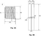
- zeigt eine schematische Seitenansicht einer beispielhaften Schleifschnecke, wobei anhand dieser Ansicht weitere Grundbegriffe definiert werden;
- FIG. 3B
- zeigt eine schematische Projektion einer Zahnlücke einer Schleifschnecke der
Fig. 3A in vergrößerter Darstellung, wobei mehrere Berührlinien eingezeichnet sind, die entstehen, wenn die Schleifschnecke zum Schleifen eines Stirnrads eingesetzt wird; - FIG. 3C
- zeigt eine stark schematisierte Abwicklung einer Zahnlücke der Schleifschnecke der
Fig. 3A in vergrößerter Darstellung, wobei nur eine Berührlinie in schematischer Form angedeutet ist; - FIG. 3D
- zeigt eine stark schematisierte Abwicklung einer einzelnen Schneckenflanke der Schleifschnecke der
Fig. 3A in vergrößerter Darstellung, wobei mehrere Berührlinien in schematischer Form angedeutet sind.
- FIG. 1
- shows a schematic perspective view of a grinding machine, which is designed to grind a workpiece with a grinding tool;
- FIG. 2A
- shows a schematic side view of an exemplary straight spur gear, based on this view basic concepts are defined;
- FIG. 2 B
- shows a schematic projection of a tooth gap of the spur gear of
Fig. 2A in an enlarged view, wherein a Berührlinie is drawn, which arises when a grinding worm would be used for grinding the spur gear without lifting movement; - FIG. 2C
- shows a schematic projection of a tooth gap of the spur gear of
Fig. 2A in an enlarged view, wherein several Berührlinien are drawn, which arise when a grinding worm is used for grinding the spur gear with lifting movement; - FIG. 3A
- shows a schematic side view of an exemplary grinding worm, based on this view further basic concepts are defined;
- FIG. 3B
- shows a schematic projection of a tooth gap of a grinding worm of
Fig. 3A in an enlarged view, wherein a plurality of contact lines are drawn, which arise when the grinding worm is used for grinding a spur gear; - FIG. 3C
- shows a highly schematic development of a tooth gap of the grinding worm of
Fig. 3A in an enlarged view, wherein only one Berührlinie is indicated in a schematic form; - FIG. 3D
- shows a highly schematic development of a single screw flank of the grinding worm of
Fig. 3A in an enlarged view, with several Berührlinien are indicated in a schematic form.
Im Zusammenhang mit der vorliegenden Beschreibung werden Begriffe verwendet, die auch in einschlägigen Publikationen und Patenten Verwendung finden. Es sei jedoch angemerkt, dass die Verwendung dieser Begriffe lediglich dem besseren Verständnis dienen soll. Der erfinderische Gedanke und der Schutzumfang der Patentansprüche soll durch die spezifische Wahl der Begriffe nicht in der Auslegung eingeschränkt werden. Die Erfindung lässt sich ohne weiteres auf andere Begriffssysteme und/oder Fachgebiete übertragen. In anderen Fachgebieten sind die Begriffe sinngemäß anzuwenden.In the context of the present description, terms are used which are also used in relevant publications and patents. It should be noted, however, that the use of these terms is for the convenience of understanding only. The inventive idea and the scope of the claims should not be limited by the specific choice of the terms in the interpretation. The invention can be without further transferred to other conceptual systems and / or subject areas. In other fields the terms are to be applied mutatis mutandis.
Wenn man die Zahnlücke 11 des geradverzahnten Stirnrades z.B. mit einer Schleifscheibe ohne Hubbewegung (d.h. ohne eine relative Bewegung achsparallel zur Werkstückrotationsachse C) schleifend bearbeiten würde, so ergäbe sich ein gerader Linienzug als Berührlinie BL. Die Berührlinie BL ergibt sich dabei aus den sich bewegenden Berührpunkten, wenn sich die Schleifscheibe um die Werkzeug(rotations)achse B dreht. Ein gerader Linienzug ergibt sich jedoch nur dann, wenn es keine relative Hubbewegung parallel zur Werkstückachse C gibt, d.h. wenn sich die Schleifscheibe nicht relativ zum Werkstück W1 bewegt.If the tooth gap 11 of the spur gear is made e.g. with a grinding wheel without reciprocating motion (i.e., without a relative movement axially parallel to the workpiece rotation axis C) would grind, then a straight line would result as the contact line BL. The contact line BL results from the moving points of contact, when the grinding wheel to the tool (rotation) axis B rotates. However, a straight line trace only results if there is no relative stroke movement parallel to the workpiece axis C, i. when the grinding wheel does not move relative to the workpiece W1.
Wenn eine Schleifschnecke 2 eingesetzt wird, dann ergibt sich auch nur eine einzige Berührlinie BL, wie in
Der in
Da eine relative Bewegung parallel zur Werkstückachse C vorgegeben wird, wandert der Berührpunkt in einer Ebene entlang der Flankenflächen LF, RF, sondern die Berührlinien BL verlaufen mit größer gewähltem Axialvorschub immer schräger. An der Darstellung der
Die Darstellungen der
In
An der Darstellung der
Aufgrund des großen Schrägungswinkels bzw. der kleinen Steigung, zeigt die Projektion der
Die Abwicklung der Schneckenflanken erhält man, indem man z.B. den Mittenzylinder der Schleifschnecke 2 betrachtet. Dieser Mittenzylinder schneidet die Flankenflächen der Flanken LF, RF in einer Schraubenlinie (bei einer modifizierten Schleifschnecke 2 handelt es sich im Allgemeinen nur näherungsweise um eine Schraubenlinie). Die Länge dieser Schraubenlinie ergibt sich jeweils als Quotient der Schneckenbreite b0 und dem Sinus des jeweiligen Steigungswinkels der Zahnflanke LF, RF an dem Mittenzylinder (Durchmesser des Zylinders). Mit wachsendem Durchmesser des Zylinders nimmt die Länge der Schraubenlinie zu. D.h. am Kopfzylinder ist die Länge der Schraubenlinie am größten. Der Unterschied zwischen der Länge der Schraubenlinie am Zahnkopf und am Zahnfuß relativ zur Schraubenlänge ist klein, da die Zahnhöhe h0 relativ klein bezüglich der Schneckenbreite b0 ist.The development of the screw flanks is obtained by looking, for example, at the center cylinder of the grinding
Es kann nun ein Bezugsdurchmesser mit einer zugehörenden Bezugsschraubenlinie und einer Bezugsschraubenlänge l0* wie folgt definiert werden: ![]()
![]()
γ0* ist der Steigungswinkel am Bezugsdurchmesser der Schleifschnecke 2. Aus dieser Umrechnung ergibt sich die gestreckte Darstellung der
In
Es lässt sich nun ableiten, dass man nach einem Abrichtvorgang durch das Anpassen des Verhältnisses zwischen dem Shiften und dem achsparallelen Bewegen eine bessere Nutzung der Schleifkörner erzielen kann. Bei mindestens einem Teil der Ausführungsformen wird dieses Verhältnis daher nach einem Abrichtvorgang oder nach mehreren Abrichtvorgängen angepasst. Mit anderen Worten kommt somit beim Wälzschleifen mit einer Schleifschnecke 2 mit großem Durchmesser d1 ein anderes Verhältnis der Relativbewegung achsparallel oder schräg zur Werkstückrotationsachse C zum Shiftweg zum Einsatz, als beim Schleifen mit einer Schleifschnecke 2, deren effektiver Durchmesser d0 durch das Abrichten kleiner geworden ist.It can now be deduced that after a dressing operation, it is possible to achieve a better utilization of the abrasive grains by adjusting the ratio between the shifting and the axis-parallel movement. In at least part of the embodiments, therefore, this ratio is adjusted after a dressing operation or after several dressing operations. With others Words thus comes in Wälzschleifen with a grinding
Im Folgenden wird der Begriff der "Eingriffsdichte EgD" eingeführt. Diese Eingriffsdichte EgD, die entlang der Schraubenlinien bzw. der Zahnlängsrichtung betrachtet wird, ist als reziproker Wert zum Schraubweg pro Werkzeugumdrehung definiert. Es gilt im Zusammenhang mit ![]()
![]()
Es gilt im Zusammenhang mit ![]()
![]()
D.h., die Eingriffsdichte EgD definiert die Anzahl der Eingriffe pro Schraubweg. Die Eingriffsdichte EgD ist beim maximalen Schleifschnecken-Durchmesser d0max deutlich geringer als beim minimalen Schleifschnecken-Durchmesser d0min (wenn das Verhältnis von Shiftweg zur achsparallelen Bewegung konstant gehalten wird).That is, the mesh density EgD defines the number of meshes per screw. The mesh density EgD is significantly lower for the maximum grinding screw diameter d0max than for the minimum grinding screw diameter d0min (if the ratio of the shiftweg to the axis-parallel movement is kept constant).
Durch die Definition der Eingriffsdichte EgD, wird nun erstmals eine quantitative Aussage möglich. Anhand dieser quantitativen Aussage kann nun die Schleifstrategie angepasst werden, um die Schleifschnecke 2 besser nutzen zu können. Das hat wiederum zur Folge, dass mit einer Schleifschnecke 2 mehr Werkstücke W1 geschliffen werden können als zuvor, wobei durch die Anwendung der neuen Schleifstrategie (genauer gesagt handelt es sich um ein Handhabungsstrategie) keine Verschlechterung der Oberflächenqualität der geschliffenen Zahnflanken verursacht wird.By defining the mesh density EgD, a quantitative statement is now possible for the first time. Based on this quantitative statement, the grinding strategy can now be adapted to make better use of the grinding
Im Folgenden wird anhand eines Zahlenbeispiels die Anwendung der Eingriffsdichte EgD zur Festlegung einer neuen Handhabungsstrategie erläutert.In the following, the application of the mesh density EgD to define a new handling strategy will be explained on the basis of a numerical example.
Es wird hier exemplarisch von einem konstanten Hub (d.h. mit einer konstanten achsparallelen Relativbewegung parallel oder schräg zur Werkstückrotationsachse C) mit einem Axialvorschub von 0,3 mm/Werkstückumdrehung ausgegangen (wie bisher beim Stand der Technik). Außerdem wird angenommen, dass die Schleifschnecke 2 einen maximalen Durchmesser d0max = 350mm und eine minimalen Durchmesser d0min = 220mm hat. Außerdem hat die Schleifschnecke 2 eine Gangzahl von 5 und das Werkstück W1 ist ein Stirnrad mit einer Zähnezahl von 29.By way of example, a constant stroke (that is to say with a constant axis-parallel relative movement parallel or obliquely to the workpiece rotation axis C) with an axial feed of 0.3 mm / workpiece rotation is assumed (as in the prior art). In addition, it is assumed that the grinding
Der Axialvorschub lässt sich wie folgt auf die Werkzeugumdrehung umrechnen. Der auf die Werkzeugumdrehung umgerechnete Axialvorschub entspricht dem Hubweg pro Werkzeugumdrehung, d.h.: ![]()
![]()
Der Shiftweg pro Werkzeugumdrehung entspricht dem Shiftweg pro Eingriff eines Schneckenzahns der Schleifschnecke 2, wie folgt: ![]()
![]()
Daraus kann man die Anzahl der Eingriffe pro Shiftweg in axialer Richtung errechnen, und es ergeben sich 769 Eingriffe pro mm Schneckenbreite.From this one can calculate the number of interventions per Shiftweg in the axial direction, and there are 769 interventions per mm worm width.
Diese Größen sind allesamt unabhängig vom effektiven Durchmesser d0 der Schleifschnecke 2. Wenn man hingegen die mit Schleifkörnern besetzte (Flanken-)Fläche entlang der Schneckenbreite b0 betrachtet, spielt der Steigungswinkel eine Rolle. Beim Durchmesser d0max = 350mm beträgt der Steigungswinkel nur 2,05°. Beim Durchmesser d0min = 220mm hingegen beträgt der Steigungswinkel 3,26°.These sizes are all independent of the effective diameter d0 of the grinding
Der Schraubweg pro Werkzeugumdrehung entspricht dem Weg entlang der Flankenfläche. Bei einer Schleifschnecke 2 mit dem Durchmesser d0max, wird der Schraubweg pro Werkzeugumdrehung wie folgt aus Gleichung 2 ermittelt: 
Bei einer Schleifschnecke 2 mit dem Durchmesser d0min, wird der Schraubweg pro Werkzeugumdrehung wie folgt aus Gleichung 2 ermittelt: 
Der Schraubweg pro Werkzeugumdrehung ist somit bei einer Schleifschnecke 2 mit kleinem Durchmesser deutlich kleiner als bei einer Schleifschnecke 2 mit großem Durchmesser. Durch den sich durchs Abrichten ändernden Durchmesser ändert sich somit der Schraubweg.The Schraubweg per tool rotation is thus significantly smaller with a grinding
Die Anzahl der Eingriffe pro Schraubweg (diese Größe wird hier per Definitionem als Eingriffsdichte EgD bezeichnet) beträgt bei einer Schleifschnecke 2 mit dem Durchmesser d0max: EgD = 27,5 Eingriffe pro mm (entlang der Flankenfläche). Die Anzahl der Eingriffe pro Schraubweg beträgt bei einer Schleifschnecke 2 mit dem Durchmesser d0min: EgD = 43,7 Eingriffe pro mm (entlang der Flankenfläche).The number of interventions per screw path (this variable is referred to by definition as the mesh density EgD) is in a grinding
Die Eingriffsdichte EgD ist beim maximalen Durchmesser d1max deutlich geringer als beim minimalen Durchmesser d1min, wenn das Verhältnis von Shiftweg zur achsparallelen Bewegung konstant gehalten wird.The engagement density EgD is significantly smaller at the maximum diameter d1max than at the minimum diameter d1min, if the ratio of shift path to axis-parallel movement is kept constant.
Nun kann bei mindestens einem Teil der Ausführungsformen anhand des folgenden Ansatzes eine Festlegung einer neuen Schleif- bzw. Handhabungsstrategie erfolgen. Wenn die Schleifschnecke 2 so entwickelt wurde, dass sie auch beim Erreichen des minimalen Durchmessers d0min noch immer zuverlässig arbeitet und gute Schleifergebnisse liefert, dann kann ausgehend von der Eingriffsdichte EgD = 43,7 Eingriffe pro mm eine geeignete Anpassung der Schleif- bzw. Handhabungsstrategie wie folgt vorgenommen werden.Now, in at least a part of the embodiments, a determination of a new grinding or handling strategy can be made based on the following approach. If the grinding
Anhand der Gleichung 2 kann rückwärts ein neuer Schraubweg pro Werkzeugumdrehung wie folgt ermittelt werden: ![]()
![]()
D.h. der Schraubweg pro Werkzeugumdrehung kann von 1,3µm auf 0,82µm reduziert werden. Ein Schraubweg von 0,82µm pro Werkzeugumdrehung entspricht dann einer Eingriffsdichte pro Shiftweg (statt einer Eingriffsdichte EgD pro Schraubweg) von 1222 Eingriffen pro mm (entlang der Schneckenbreite). Daraus lässt sich ein Shiftweg pro Hubweg von 0,016mm/mm errechnen (allgemein wird dieses Verhältnis hier auch als Verhältnis des Shiftwegs zu der achsparallelen Bewegung parallel oder schräg zur Werkstückrotationsachse C bezeichnet). Dies entspricht einer Ersparnis von 36% am erforderlichen Shiftweg für den betrachteten Hub. Diese Betrachtung ist unabhängig vom konkreten Axialvorschub und gilt somit für Schlicht- und Schrupphübe.That The screw travel per tool revolution can be reduced from 1.3μm to 0.82μm. A screw travel of 0.82 μm per tool revolution then corresponds to an engagement density per shift path (instead of an engagement density EgD per screw travel) of 1222 interventions per mm (along the worm width). From this a Shiftweg per stroke of 0.016mm / mm can be calculated (in general, this ratio is also referred to here as the ratio of Shiftwegs to the axis-parallel movement parallel or obliquely to the workpiece rotation axis C). This corresponds to a saving of 36% of the required shift travel for the considered stroke. This consideration is independent of the actual axial feed and thus applies to finishing and roughing strokes.
Eine beispielhafte neue Schleif- oder Handhabungsstrategie kann nun z.B. wie folgt aussehen. Beim Erreichen des minimalen Durchmessers d0min kann z.B. ein Shiftweg pro Hubweg von 0,025mm/mm vorgegeben werden. Beim Schleifen mit einer Schleifschnecke 2, deren Durchmesser dem Maximaldurchmesser d0max entspricht, kann z.B. ein Shiftweg pro Hubweg von 0,016mm/mm vorgegeben werden. Das Schleifen mit einer neuen (noch nicht oder nur wenig abgerichteten Schleifschnecke 2) beginnt mit einem Verhältnis von Shiftweg zum Hubweg von 0,016. Wenn man von einem linearen Zusammenhang ausgeht, dann kann nach jedem Abrichten das Verhältnis von Shiftweg zum Hubweg schrittweise linear von 0,016 bis 0,025 verändert werden.An exemplary new grinding or handling strategy may now be used e.g. look like this. Upon reaching the minimum diameter d0min, e.g. Shiftweg per stroke of 0.025mm / mm are given. When grinding with a grinding
Dieser Ansatz liefert sehr gute Ergebnisse, da genauere Untersuchungen gezeigt haben, dass die Abhängigkeit der Eingriffsdichte EgD vom Schleifschnecken-Durchmesser d0 näherungsweise linear verläuft.This approach gives very good results since more detailed investigations have shown that the dependence of the mesh density EgD on the grinding wheel diameter d0 is approximately linear.
Wenn man weiter davon ausgeht, das beim Anwenden der konventionellen kontinuierlichen Shiftstrategie mit konstantem Verhältnis von Shiftweg zum Hubweg 28 Werkstücke W1 je Abrichten bei ca. 270 möglichen Abrichtvorgängen bearbeitet werden konnten, so konnte man mit dieser konventionellen Strategie ca. 28 * 270 = 7560 Werkstücke W1 mit einer Schleifschnecke 2 schleifen.Assuming the conventional continuous shift strategy with a constant ratio of Shiftweg to stroke 28 workpieces W1 per dressing was able to be machined with approximately 270 possible dressing operations, this conventional strategy allowed for approximately 28 * 270 = 7560 workpieces Grind W1 with a grinding
Mit der neuen Shift- bzw. Handhabungsstrategie, die ein veränderliches Verhältnis vorsieht, kann man statt der 28 Werkstücke ca. 43,5 Werkstücke beim Maximaldurchmesser d0max vor dem ersten Abrichten fertigen. Wenn man von einem linearen Zusammenhang ausgeht, kann die Anzahl der über den gesamten Durchmesserbereich der Schleifschnecke 2 fertigbaren Werkstücke W1 wie folgt abschätzen: 
9652 Werkstücke sind ca. 28% mehr als 7560 Werkstücke, die mit der konventionellen, kontinuierlichen Shiftstrategie geschliffen werden können. D.h. durch das lineare Anpassen des Verhältnisses von Shiftweg zum Hubweg jeweils nach dem Abrichten kann das Schleifverfahren deutlich optimiert werden.9652 workpieces are approx. 28% more than 7560 workpieces which can be ground with the conventional, continuous shift strategy. That By linearly adjusting the ratio of Shiftweg to stroke each time after dressing, the grinding process can be significantly optimized.
Die Anpassung des Verhältnisses von Shiftweg zur achsparallelen Relativbewegung kann auch in Abhängigkeit von dem effektiven Durchmesser d0 der Schleifschnecke 2 vorgenommen werden. Zu diesem Zweck kann der Durchmesser d0 jeweils nach dem Abrichten ermittelt werden, um dann auf rechnerischem Wege unter Einsatz einer Gleichung das Verhältnis von Shiftweg zur achsparallelen Bewegung für die Schleifvorgänge, die nach dem Abrichten folgend, vorzugeben.The adaptation of the ratio of Shiftweg axis-parallel relative movement can also be made depending on the effective diameter d0 of the grinding
Statt der Zahnhöhe h0 kann zum rechnerischen Annähern an die Zahnflankenfläche auch die skalierte Größe h0/cos(αn0) genutzt werden, wobei αn0 der Normaleingriffswinkel ist. Da die Eingriffsdichte EgD in den oben beschriebenen Ausführungsformen der Einfachheit halber in Richtung der Schraubenlinien (Zahnlängsrichtung) betrachtet wurde (siehe auch
Eine genauere Betrachtung der Abstände zwischen Berührlinien kBL kann z.B. erfolgen, in dem der Abstand Δz nicht entlang der Schraubenlinie (wie in
Aus diesem Weg erhält man eine etwas genauere Gleichung, die bei allen Ausführungsformen nach dem Abrichten zum Anpassen des Verhältnisses von Shiftweg zur achsparallelen Bewegung genutzt werden kann.From this approach, one obtains a somewhat more accurate equation that can be used in all embodiments after dressing to adjust the ratio of shift travel to axis-parallel motion.
Statt eine lineare Anpassung des Verhältnisses von Shiftweg zur achsparallelen Relativbewegung vorzunehmen, kann diese Anpassung bei allen Ausführungsformen nach dem Abrichten auch nicht-linear vorgenommen werden.Instead of making a linear adjustment of the ratio of Shiftweg axis-parallel relative movement, this adjustment can also be made non-linear in all embodiments after dressing.
Statt eine lineare Anpassung des Verhältnisses von Shiftweg zur achsparallelen Relativbewegung vorzunehmen, kann diese Anpassung bei allen Ausführungsformen nach dem Abrichten auch durch das Auslesen von zuvor abgespeicherten Werten aus einer Datenbank (z.B. durch einen table-look-up) vorgenommen werden. Bei diesen Ausführungsformen kommt dann eine schrittweise (bereichsweise) Anpassung des Verhältnisses von Shiftweg zur achsparallelen Relativbewegung zur Anwendung.Instead of making a linear adjustment of the ratio of Shiftweg to the axis-parallel relative movement, this adaptation can be done in all embodiments after dressing by reading previously stored values from a database (for example, by a table-look-up). In these embodiments, then a gradual (regional) adjustment of the ratio of Shiftweg for axis-parallel relative movement is used.
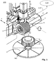
Eine Schleifmaschine 100 der Erfindung kann z.B. mit einer Werkzeugspindel 1 zum Aufnehmen und Drehantreiben eines Schleifwerkzeugs 2 um eine Werkzeugrotationsachse B (kurz auch als Werkzeugachse bezeichnet) ausgestattet sein. Weiterhin kann die Schleifmaschine 100 beispielsweise eine Werkstückspindel 3 zum Aufnehmen eines Werkstücks W1 umfassen. Außerdem umfasst die Maschine 100 eine Abrichtvorrichtung 112 mit einem Abrichter 4 und die Maschine 100 ist so ausgelegt, dass mittels des Abrichters 4 ein Abrichtvorgang ohne Umspannen des Schleifwerkzeugs 2 erfolgen kann. In
Weiterhin umfasst die Schleifmaschine 100 eine Steuerung 110. In
Bei einem Teil der Ausführungsformen übernimmt Steuerung 110 das lineare oder nicht-lineare Anpassen des Verhältnisses von Shiftweg zum Hubweg jeweils nach dem Abrichten der Schleifschnecke 2.In a portion of the embodiments,
Die Anordnung und Ausgestaltung der Achsen der Schleifmaschine 100 sind lediglich als Beispiel zu verstehen. Es gibt zahlreiche andere Achskonstellationen, die auch geeignet sind. Auch müssen die Relativbewegungen, die hier beschrieben sind, nicht durch das Bewegen einer einzelnen Achse (z.B. der Hubachse X) ausgeführt werden. Jede der Bewegungen kann auch durch die Überlagerung von zwei oder mehr als zwei Achsbewegungen erzeugt werden.The arrangement and configuration of the axes of the grinding
Das Anpassen des genannten Verhältnisses erfolgt vorzugsweise nach jedem Abrichten der Schleifschnecke 2. Das Anpassen des genannten Verhältnisses kann aber auch z.B. nur nach jedem zweiten Abrichten oder in einem anderen Intervall vorgenommen werden.The adaptation of said ratio is preferably carried out after each dressing of the grinding
Das Anpassen "nach dem Abrichten" schliesst auch ein Anpassen mit ein, das erst unmittelbar vor dem erneuten Einsatz einer zuvor abgerichteten Schleifschnecke 2 zum Wälzschleifen erfolgen kann.The adaptation "after dressing" also includes an adjustment that can be made only immediately before the re-use of a previously trained grinding
Das Anpassen des genannten Verhältnisses kann in kleinen Schritten erfolgen. Wenn z.B. mit einer bestimmten Schleifschnecke 2 insgesamt 2000 Werkstücke W1 geschliffen werden können und wenn die Eingriffsdichte EgD zwischen 0,01 und 0,03 liegt, dann kann die Differenz zwischen 0,03 und 0,01 durch 2000 geteilt werden. Dadurch erhält man 2000 Mikroschritte mit je 0,00001mm/mm. In diesem Fall nimmt die Steuerung 110 Schritt für Schritt kleine Änderungen des Verhältnisses jeweils nach jedem Abrichtvorgang vor.
Claims (20)
Applications Claiming Priority (1)
| Application Number | Priority Date | Filing Date | Title |
|---|---|---|---|
| DE102018109067.6A DE102018109067A1 (en) | 2018-04-17 | 2018-04-17 | A method of gear grinding a gear workpiece and a grinding machine with a control for generating grinding of a gear workpiece |
Publications (3)
| Publication Number | Publication Date |
|---|---|
| EP3556501A1 true EP3556501A1 (en) | 2019-10-23 |
| EP3556501B1 EP3556501B1 (en) | 2020-09-09 |
| EP3556501B2 EP3556501B2 (en) | 2024-01-10 |
Family
ID=66049063
Family Applications (1)
| Application Number | Title | Priority Date | Filing Date |
|---|---|---|---|
| EP19166536.3A Active EP3556501B2 (en) | 2018-04-17 | 2019-04-01 | Method for grinding a cogged workpiece and grinding machine with a controller for grinding a cogged workpiece |
Country Status (8)
| Country | Link |
|---|---|
| US (1) | US11559843B2 (en) |
| EP (1) | EP3556501B2 (en) |
| JP (1) | JP7430984B2 (en) |
| KR (1) | KR102790095B1 (en) |
| CN (1) | CN110385605B (en) |
| CA (1) | CA3038931A1 (en) |
| DE (1) | DE102018109067A1 (en) |
| MX (1) | MX2019003394A (en) |
Families Citing this family (10)
| Publication number | Priority date | Publication date | Assignee | Title |
|---|---|---|---|---|
| DE102018114820A1 (en) | 2018-06-20 | 2019-12-24 | Klingelnberg Gmbh | Method for topological generating grinding of gear workpieces and grinding machine with a control for topological generating grinding of gear workpieces |
| JP7310708B2 (en) * | 2020-05-20 | 2023-07-19 | トヨタ自動車株式会社 | Composite grinding wheel and grinding device equipped with it |
| CH718158A1 (en) * | 2020-12-15 | 2022-06-15 | Reishauer Ag | Process for machining a workpiece in a gear grinding machine with conditioning of a superabrasive grinding tool. |
| CN113400197B (en) * | 2021-06-23 | 2022-07-26 | 重庆大学 | Method for shaping and trimming drum-shaped worm grinding wheel for grinding face gear |
| CN114483914B (en) * | 2021-10-27 | 2023-05-09 | 长安大学 | A point contact grinding method for diagonally modified helical gears |
| CN114515872B (en) * | 2022-03-23 | 2023-12-08 | 陕西法士特齿轮有限责任公司 | Grinding wheel tool shifting method for processing anti-twisting grinding teeth |
| CH719789B1 (en) * | 2022-12-19 | 2023-12-29 | Reishauer Ag | Method and device for producing a modified surface structure on a tooth flank |
| CH721079B1 (en) * | 2024-02-26 | 2025-03-14 | Reishauer Ag | Process for machining pre-toothed workpieces by continuous generating grinding and corresponding gear cutting machine |
| CH721080B1 (en) * | 2024-02-26 | 2025-03-14 | Reishauer Ag | Process for machining pre-toothed workpieces by continuous generating grinding and corresponding gear cutting machine |
| CN119747757B (en) * | 2024-12-11 | 2025-09-23 | 河南科技大学 | Forming and grinding method for simultaneously grinding multiple tooth grooves of internal gear |
Citations (3)
| Publication number | Priority date | Publication date | Assignee | Title |
|---|---|---|---|---|
| DE102012017840B3 (en) * | 2012-09-08 | 2013-12-12 | Klingelnberg Gmbh | Gear grinding machine makes angle between straight line of axis of rotation of straightening roller and vector of straightening direction of straightening roller |
| DE112012006475T5 (en) * | 2012-06-06 | 2015-03-12 | Ai Machine Tech Co., Ltd. | Tooth flank processing device and gear manufacturing method |
| EP3242175A2 (en) * | 2016-04-28 | 2017-11-08 | Liebherr-Verzahntechnik GmbH | Method for cogging a workpiece |
Family Cites Families (8)
| Publication number | Priority date | Publication date | Assignee | Title |
|---|---|---|---|---|
| US7682222B2 (en) * | 2004-05-26 | 2010-03-23 | The Gleason Works | Variable rate method of machining gears |
| JP4202306B2 (en) | 2004-07-29 | 2008-12-24 | 三菱重工業株式会社 | Gear grinding machine |
| US8277285B2 (en) | 2006-05-24 | 2012-10-02 | The Gleason Works | Method of maintaining a constant grinding process |
| DE102011015447A1 (en) * | 2011-03-29 | 2012-10-25 | Liebherr-Verzahntechnik Gmbh | gear cutting |
| DE102015000975A1 (en) * | 2015-01-23 | 2016-07-28 | Liebherr-Verzahntechnik Gmbh | Method for producing a workpiece with corrected tooth geometry and / or modified surface structure |
| DE102015012308A1 (en) * | 2015-09-23 | 2017-03-23 | Liebherr-Verzahntechnik Gmbh | Method for producing a workpiece with modified tooth geometry |
| CN107552894A (en) | 2017-09-05 | 2018-01-09 | 盐城秦川华兴机床有限公司 | Vertical numerical control skiving machine |
| DE102018114820A1 (en) * | 2018-06-20 | 2019-12-24 | Klingelnberg Gmbh | Method for topological generating grinding of gear workpieces and grinding machine with a control for topological generating grinding of gear workpieces |
-
2018
- 2018-04-17 DE DE102018109067.6A patent/DE102018109067A1/en not_active Withdrawn
-
2019
- 2019-03-25 MX MX2019003394A patent/MX2019003394A/en unknown
- 2019-03-29 JP JP2019066092A patent/JP7430984B2/en active Active
- 2019-04-01 EP EP19166536.3A patent/EP3556501B2/en active Active
- 2019-04-02 CA CA3038931A patent/CA3038931A1/en active Pending
- 2019-04-04 KR KR1020190039355A patent/KR102790095B1/en active Active
- 2019-04-12 US US16/382,837 patent/US11559843B2/en active Active
- 2019-04-16 CN CN201910301831.5A patent/CN110385605B/en active Active
Patent Citations (3)
| Publication number | Priority date | Publication date | Assignee | Title |
|---|---|---|---|---|
| DE112012006475T5 (en) * | 2012-06-06 | 2015-03-12 | Ai Machine Tech Co., Ltd. | Tooth flank processing device and gear manufacturing method |
| DE102012017840B3 (en) * | 2012-09-08 | 2013-12-12 | Klingelnberg Gmbh | Gear grinding machine makes angle between straight line of axis of rotation of straightening roller and vector of straightening direction of straightening roller |
| EP3242175A2 (en) * | 2016-04-28 | 2017-11-08 | Liebherr-Verzahntechnik GmbH | Method for cogging a workpiece |
Also Published As
| Publication number | Publication date |
|---|---|
| MX2019003394A (en) | 2019-10-18 |
| CN110385605B (en) | 2022-10-14 |
| JP7430984B2 (en) | 2024-02-14 |
| DE102018109067A1 (en) | 2019-10-17 |
| KR102790095B1 (en) | 2025-04-01 |
| US20190314913A1 (en) | 2019-10-17 |
| US11559843B2 (en) | 2023-01-24 |
| KR20190121244A (en) | 2019-10-25 |
| CA3038931A1 (en) | 2019-10-17 |
| JP2019181688A (en) | 2019-10-24 |
| EP3556501B2 (en) | 2024-01-10 |
| CN110385605A (en) | 2019-10-29 |
| EP3556501B1 (en) | 2020-09-09 |
Similar Documents
| Publication | Publication Date | Title |
|---|---|---|
| EP3556501B1 (en) | Method for grinding a cogged workpiece and grinding machine with a controller for grinding a cogged workpiece | |
| DE102004057596B4 (en) | Profiling gear and method for profiling a grinding worm | |
| DE19706867C5 (en) | Profiling methods for the production of modified grinding worms | |
| EP2895290B1 (en) | Method for modifying the flanks of a tooth of a gear wheel with the aid of a tool | |
| EP2412467B1 (en) | Method for machining bevelled wheel cogging in a continuous machining method | |
| EP3584025A1 (en) | Method for topological grinding of a cogged workpiece and grinding machine with a controller for topological grinding of a cogged workpiece | |
| EP0074930B1 (en) | Generating method for cutting involute tooth flanks with profile and longitudinal corrections | |
| EP3147059B1 (en) | Method for the production of a workpiece with modified toothing geometry | |
| EP2397249A1 (en) | Method for processing a cog, workpiece with cog and machine tool | |
| EP3050660A1 (en) | Method for gear cutting a piece by means of a diagonal generating method | |
| EP2036673B1 (en) | Method for dressing a tool used for fine machining of gears | |
| WO2011047957A1 (en) | Method for hard fine machining of the flanks of a gear wheel | |
| EP3050659A1 (en) | Method and device for gear cutting a workpiece by means of a diagonal generating method | |
| DE102015009287A1 (en) | Method for producing a workpiece with a desired tooth geometry | |
| DE102015009017A1 (en) | Method for producing a toothed workpiece with a modified surface geometry | |
| EP0311778A2 (en) | Method for finishing crowned tooth flanks, in particular of hardened gears | |
| EP3348354B1 (en) | Method for processing bevel gears using an eccentrically moved, dressable cup grinding disc | |
| EP3838463A1 (en) | Method for fine processing of a toothed workpiece | |
| EP3053687B1 (en) | Method and device for gear cutting a workpiece by means of a diagonal milling method | |
| DE102007043404A1 (en) | Circular tool dressing method for e.g. fine machining gear of gear wheel, involves rotatingly driving dressing wheel and tool, where breadth of gear of wheel is smaller than tool's breadth so that wheel is moved around length in z-direction | |
| EP2851150B1 (en) | Tool, method and machine for generating a toothed profile on a workpiece by skiving | |
| DE102018126259A1 (en) | Process for dressing a grinding worm and device for dressing a grinding worm | |
| EP3139228B1 (en) | Method for producing one or more workpieces | |
| DD279627A1 (en) | METHOD AND DEVICE FOR PRODUCING STRAIGHT OR CROWNED HEADDRESSES WITH LENGTH AND HEAVY BALLIFIED MODIFIED TOOTHED FLANKS | |
| EP4257276A1 (en) | Method for dressing a multi-thread grinding worm |
Legal Events
| Date | Code | Title | Description |
|---|---|---|---|
| PUAI | Public reference made under article 153(3) epc to a published international application that has entered the european phase |
Free format text: ORIGINAL CODE: 0009012 |
|
| STAA | Information on the status of an ep patent application or granted ep patent |
Free format text: STATUS: THE APPLICATION HAS BEEN PUBLISHED |
|
| AK | Designated contracting states |
Kind code of ref document: A1 Designated state(s): AL AT BE BG CH CY CZ DE DK EE ES FI FR GB GR HR HU IE IS IT LI LT LU LV MC MK MT NL NO PL PT RO RS SE SI SK SM TR |
|
| AX | Request for extension of the european patent |
Extension state: BA ME |
|
| STAA | Information on the status of an ep patent application or granted ep patent |
Free format text: STATUS: REQUEST FOR EXAMINATION WAS MADE |
|
| 17P | Request for examination filed |
Effective date: 20191031 |
|
| RBV | Designated contracting states (corrected) |
Designated state(s): AL AT BE BG CH CY CZ DE DK EE ES FI FR GB GR HR HU IE IS IT LI LT LU LV MC MK MT NL NO PL PT RO RS SE SI SK SM TR |
|
| GRAP | Despatch of communication of intention to grant a patent |
Free format text: ORIGINAL CODE: EPIDOSNIGR1 |
|
| STAA | Information on the status of an ep patent application or granted ep patent |
Free format text: STATUS: GRANT OF PATENT IS INTENDED |
|
| INTG | Intention to grant announced |
Effective date: 20200211 |
|
| GRAJ | Information related to disapproval of communication of intention to grant by the applicant or resumption of examination proceedings by the epo deleted |
Free format text: ORIGINAL CODE: EPIDOSDIGR1 |
|
| STAA | Information on the status of an ep patent application or granted ep patent |
Free format text: STATUS: REQUEST FOR EXAMINATION WAS MADE |
|
| GRAS | Grant fee paid |
Free format text: ORIGINAL CODE: EPIDOSNIGR3 |
|
| STAA | Information on the status of an ep patent application or granted ep patent |
Free format text: STATUS: GRANT OF PATENT IS INTENDED |
|
| GRAP | Despatch of communication of intention to grant a patent |
Free format text: ORIGINAL CODE: EPIDOSNIGR1 |
|
| INTC | Intention to grant announced (deleted) | ||
| INTG | Intention to grant announced |
Effective date: 20200710 |
|
| GRAA | (expected) grant |
Free format text: ORIGINAL CODE: 0009210 |
|
| STAA | Information on the status of an ep patent application or granted ep patent |
Free format text: STATUS: THE PATENT HAS BEEN GRANTED |
|
| AK | Designated contracting states |
Kind code of ref document: B1 Designated state(s): AL AT BE BG CH CY CZ DE DK EE ES FI FR GB GR HR HU IE IS IT LI LT LU LV MC MK MT NL NO PL PT RO RS SE SI SK SM TR |
|
| REG | Reference to a national code |
Ref country code: GB Ref legal event code: FG4D Free format text: NOT ENGLISH |
|
| REG | Reference to a national code |
Ref country code: AT Ref legal event code: REF Ref document number: 1310953 Country of ref document: AT Kind code of ref document: T Effective date: 20200915 Ref country code: CH Ref legal event code: EP |
|
| REG | Reference to a national code |
Ref country code: DE Ref legal event code: R096 Ref document number: 502019000198 Country of ref document: DE |
|
| REG | Reference to a national code |
Ref country code: IE Ref legal event code: FG4D Free format text: LANGUAGE OF EP DOCUMENT: GERMAN |
|
| REG | Reference to a national code |
Ref country code: CH Ref legal event code: NV Representative=s name: TROESCH SCHEIDEGGER WERNER AG, CH |
|
| REG | Reference to a national code |
Ref country code: LT Ref legal event code: MG4D |
|
| PG25 | Lapsed in a contracting state [announced via postgrant information from national office to epo] |
Ref country code: LT Free format text: LAPSE BECAUSE OF FAILURE TO SUBMIT A TRANSLATION OF THE DESCRIPTION OR TO PAY THE FEE WITHIN THE PRESCRIBED TIME-LIMIT Effective date: 20200909 Ref country code: HR Free format text: LAPSE BECAUSE OF FAILURE TO SUBMIT A TRANSLATION OF THE DESCRIPTION OR TO PAY THE FEE WITHIN THE PRESCRIBED TIME-LIMIT Effective date: 20200909 Ref country code: FI Free format text: LAPSE BECAUSE OF FAILURE TO SUBMIT A TRANSLATION OF THE DESCRIPTION OR TO PAY THE FEE WITHIN THE PRESCRIBED TIME-LIMIT Effective date: 20200909 Ref country code: GR Free format text: LAPSE BECAUSE OF FAILURE TO SUBMIT A TRANSLATION OF THE DESCRIPTION OR TO PAY THE FEE WITHIN THE PRESCRIBED TIME-LIMIT Effective date: 20201210 Ref country code: BG Free format text: LAPSE BECAUSE OF FAILURE TO SUBMIT A TRANSLATION OF THE DESCRIPTION OR TO PAY THE FEE WITHIN THE PRESCRIBED TIME-LIMIT Effective date: 20201209 Ref country code: NO Free format text: LAPSE BECAUSE OF FAILURE TO SUBMIT A TRANSLATION OF THE DESCRIPTION OR TO PAY THE FEE WITHIN THE PRESCRIBED TIME-LIMIT Effective date: 20201209 Ref country code: SE Free format text: LAPSE BECAUSE OF FAILURE TO SUBMIT A TRANSLATION OF THE DESCRIPTION OR TO PAY THE FEE WITHIN THE PRESCRIBED TIME-LIMIT Effective date: 20200909 |
|
| REG | Reference to a national code |
Ref country code: NL Ref legal event code: MP Effective date: 20200909 |
|
| PG25 | Lapsed in a contracting state [announced via postgrant information from national office to epo] |
Ref country code: RS Free format text: LAPSE BECAUSE OF FAILURE TO SUBMIT A TRANSLATION OF THE DESCRIPTION OR TO PAY THE FEE WITHIN THE PRESCRIBED TIME-LIMIT Effective date: 20200909 Ref country code: PL Free format text: LAPSE BECAUSE OF FAILURE TO SUBMIT A TRANSLATION OF THE DESCRIPTION OR TO PAY THE FEE WITHIN THE PRESCRIBED TIME-LIMIT Effective date: 20200909 Ref country code: LV Free format text: LAPSE BECAUSE OF FAILURE TO SUBMIT A TRANSLATION OF THE DESCRIPTION OR TO PAY THE FEE WITHIN THE PRESCRIBED TIME-LIMIT Effective date: 20200909 |
|
| PG25 | Lapsed in a contracting state [announced via postgrant information from national office to epo] |
Ref country code: PT Free format text: LAPSE BECAUSE OF FAILURE TO SUBMIT A TRANSLATION OF THE DESCRIPTION OR TO PAY THE FEE WITHIN THE PRESCRIBED TIME-LIMIT Effective date: 20210111 Ref country code: RO Free format text: LAPSE BECAUSE OF FAILURE TO SUBMIT A TRANSLATION OF THE DESCRIPTION OR TO PAY THE FEE WITHIN THE PRESCRIBED TIME-LIMIT Effective date: 20200909 Ref country code: CZ Free format text: LAPSE BECAUSE OF FAILURE TO SUBMIT A TRANSLATION OF THE DESCRIPTION OR TO PAY THE FEE WITHIN THE PRESCRIBED TIME-LIMIT Effective date: 20200909 Ref country code: EE Free format text: LAPSE BECAUSE OF FAILURE TO SUBMIT A TRANSLATION OF THE DESCRIPTION OR TO PAY THE FEE WITHIN THE PRESCRIBED TIME-LIMIT Effective date: 20200909 Ref country code: SM Free format text: LAPSE BECAUSE OF FAILURE TO SUBMIT A TRANSLATION OF THE DESCRIPTION OR TO PAY THE FEE WITHIN THE PRESCRIBED TIME-LIMIT Effective date: 20200909 |
|
| PG25 | Lapsed in a contracting state [announced via postgrant information from national office to epo] |
Ref country code: IS Free format text: LAPSE BECAUSE OF FAILURE TO SUBMIT A TRANSLATION OF THE DESCRIPTION OR TO PAY THE FEE WITHIN THE PRESCRIBED TIME-LIMIT Effective date: 20210109 Ref country code: AL Free format text: LAPSE BECAUSE OF FAILURE TO SUBMIT A TRANSLATION OF THE DESCRIPTION OR TO PAY THE FEE WITHIN THE PRESCRIBED TIME-LIMIT Effective date: 20200909 Ref country code: ES Free format text: LAPSE BECAUSE OF FAILURE TO SUBMIT A TRANSLATION OF THE DESCRIPTION OR TO PAY THE FEE WITHIN THE PRESCRIBED TIME-LIMIT Effective date: 20200909 |
|
| REG | Reference to a national code |
Ref country code: DE Ref legal event code: R026 Ref document number: 502019000198 Country of ref document: DE |
|
| PLBI | Opposition filed |
Free format text: ORIGINAL CODE: 0009260 |
|
| PLAX | Notice of opposition and request to file observation + time limit sent |
Free format text: ORIGINAL CODE: EPIDOSNOBS2 |
|
| PG25 | Lapsed in a contracting state [announced via postgrant information from national office to epo] |
Ref country code: SK Free format text: LAPSE BECAUSE OF FAILURE TO SUBMIT A TRANSLATION OF THE DESCRIPTION OR TO PAY THE FEE WITHIN THE PRESCRIBED TIME-LIMIT Effective date: 20200909 |
|
| 26 | Opposition filed |
Opponent name: REISHAUER AG Effective date: 20210608 |
|
| PG25 | Lapsed in a contracting state [announced via postgrant information from national office to epo] |
Ref country code: DK Free format text: LAPSE BECAUSE OF FAILURE TO SUBMIT A TRANSLATION OF THE DESCRIPTION OR TO PAY THE FEE WITHIN THE PRESCRIBED TIME-LIMIT Effective date: 20200909 Ref country code: SI Free format text: LAPSE BECAUSE OF FAILURE TO SUBMIT A TRANSLATION OF THE DESCRIPTION OR TO PAY THE FEE WITHIN THE PRESCRIBED TIME-LIMIT Effective date: 20200909 |
|
| PLBB | Reply of patent proprietor to notice(s) of opposition received |
Free format text: ORIGINAL CODE: EPIDOSNOBS3 |
|
| PG25 | Lapsed in a contracting state [announced via postgrant information from national office to epo] |
Ref country code: MC Free format text: LAPSE BECAUSE OF FAILURE TO SUBMIT A TRANSLATION OF THE DESCRIPTION OR TO PAY THE FEE WITHIN THE PRESCRIBED TIME-LIMIT Effective date: 20200909 |
|
| PG25 | Lapsed in a contracting state [announced via postgrant information from national office to epo] |
Ref country code: LU Free format text: LAPSE BECAUSE OF NON-PAYMENT OF DUE FEES Effective date: 20210401 |
|
| REG | Reference to a national code |
Ref country code: BE Ref legal event code: MM Effective date: 20210430 |
|
| PG25 | Lapsed in a contracting state [announced via postgrant information from national office to epo] |
Ref country code: FR Free format text: LAPSE BECAUSE OF NON-PAYMENT OF DUE FEES Effective date: 20210430 |
|
| PG25 | Lapsed in a contracting state [announced via postgrant information from national office to epo] |
Ref country code: IE Free format text: LAPSE BECAUSE OF NON-PAYMENT OF DUE FEES Effective date: 20210401 |
|
| PG25 | Lapsed in a contracting state [announced via postgrant information from national office to epo] |
Ref country code: IS Free format text: LAPSE BECAUSE OF FAILURE TO SUBMIT A TRANSLATION OF THE DESCRIPTION OR TO PAY THE FEE WITHIN THE PRESCRIBED TIME-LIMIT Effective date: 20210109 |
|
| PG25 | Lapsed in a contracting state [announced via postgrant information from national office to epo] |
Ref country code: BE Free format text: LAPSE BECAUSE OF NON-PAYMENT OF DUE FEES Effective date: 20210430 |
|
| PG25 | Lapsed in a contracting state [announced via postgrant information from national office to epo] |
Ref country code: NL Free format text: LAPSE BECAUSE OF NON-PAYMENT OF DUE FEES Effective date: 20200923 Ref country code: CY Free format text: LAPSE BECAUSE OF FAILURE TO SUBMIT A TRANSLATION OF THE DESCRIPTION OR TO PAY THE FEE WITHIN THE PRESCRIBED TIME-LIMIT Effective date: 20200909 |
|
| PG25 | Lapsed in a contracting state [announced via postgrant information from national office to epo] |
Ref country code: HU Free format text: LAPSE BECAUSE OF FAILURE TO SUBMIT A TRANSLATION OF THE DESCRIPTION OR TO PAY THE FEE WITHIN THE PRESCRIBED TIME-LIMIT; INVALID AB INITIO Effective date: 20190401 |
|
| PUAH | Patent maintained in amended form |
Free format text: ORIGINAL CODE: 0009272 |
|
| STAA | Information on the status of an ep patent application or granted ep patent |
Free format text: STATUS: PATENT MAINTAINED AS AMENDED |
|
| GBPC | Gb: european patent ceased through non-payment of renewal fee |
Effective date: 20230401 |
|
| 27A | Patent maintained in amended form |
Effective date: 20240110 |
|
| AK | Designated contracting states |
Kind code of ref document: B2 Designated state(s): AL AT BE BG CH CY CZ DE DK EE ES FI FR GB GR HR HU IE IS IT LI LT LU LV MC MK MT NL NO PL PT RO RS SE SI SK SM TR |
|
| REG | Reference to a national code |
Ref country code: DE Ref legal event code: R102 Ref document number: 502019000198 Country of ref document: DE |
|
| PG25 | Lapsed in a contracting state [announced via postgrant information from national office to epo] |
Ref country code: GB Free format text: LAPSE BECAUSE OF NON-PAYMENT OF DUE FEES Effective date: 20230401 |
|
| PG25 | Lapsed in a contracting state [announced via postgrant information from national office to epo] |
Ref country code: GB Free format text: LAPSE BECAUSE OF NON-PAYMENT OF DUE FEES Effective date: 20230401 |
|
| PG25 | Lapsed in a contracting state [announced via postgrant information from national office to epo] |
Ref country code: MK Free format text: LAPSE BECAUSE OF FAILURE TO SUBMIT A TRANSLATION OF THE DESCRIPTION OR TO PAY THE FEE WITHIN THE PRESCRIBED TIME-LIMIT Effective date: 20200909 |
|
| PG25 | Lapsed in a contracting state [announced via postgrant information from national office to epo] |
Ref country code: MT Free format text: LAPSE BECAUSE OF FAILURE TO SUBMIT A TRANSLATION OF THE DESCRIPTION OR TO PAY THE FEE WITHIN THE PRESCRIBED TIME-LIMIT Effective date: 20200909 |
|
| REG | Reference to a national code |
Ref country code: AT Ref legal event code: MM01 Ref document number: 1310953 Country of ref document: AT Kind code of ref document: T Effective date: 20240401 |
|
| PGFP | Annual fee paid to national office [announced via postgrant information from national office to epo] |
Ref country code: DE Payment date: 20250422 Year of fee payment: 7 |
|
| PGFP | Annual fee paid to national office [announced via postgrant information from national office to epo] |
Ref country code: IT Payment date: 20250424 Year of fee payment: 7 |
|
| PGFP | Annual fee paid to national office [announced via postgrant information from national office to epo] |
Ref country code: CH Payment date: 20250501 Year of fee payment: 7 |
|
| PG25 | Lapsed in a contracting state [announced via postgrant information from national office to epo] |
Ref country code: AT Free format text: LAPSE BECAUSE OF NON-PAYMENT OF DUE FEES Effective date: 20240401 |
|
| PG25 | Lapsed in a contracting state [announced via postgrant information from national office to epo] |
Ref country code: TR Free format text: LAPSE BECAUSE OF FAILURE TO SUBMIT A TRANSLATION OF THE DESCRIPTION OR TO PAY THE FEE WITHIN THE PRESCRIBED TIME-LIMIT Effective date: 20200909 |