EP2412467B1 - Method for machining bevelled wheel cogging in a continuous machining method - Google Patents
Method for machining bevelled wheel cogging in a continuous machining method Download PDFInfo
- Publication number
- EP2412467B1 EP2412467B1 EP10171235.4A EP10171235A EP2412467B1 EP 2412467 B1 EP2412467 B1 EP 2412467B1 EP 10171235 A EP10171235 A EP 10171235A EP 2412467 B1 EP2412467 B1 EP 2412467B1
- Authority
- EP
- European Patent Office
- Prior art keywords
- cutting
- milling
- bevel gear
- continuous
- machine
- Prior art date
- Legal status (The legal status is an assumption and is not a legal conclusion. Google has not performed a legal analysis and makes no representation as to the accuracy of the status listed.)
- Active
Links
- 238000000034 method Methods 0.000 title claims description 47
- 238000003754 machining Methods 0.000 title description 11
- 238000005520 cutting process Methods 0.000 claims description 93
- 238000003801 milling Methods 0.000 claims description 28
- 230000008859 change Effects 0.000 claims description 11
- 238000011437 continuous method Methods 0.000 claims description 4
- 238000012986 modification Methods 0.000 claims description 4
- 230000004048 modification Effects 0.000 claims description 4
- 230000008569 process Effects 0.000 description 10
- 238000010924 continuous production Methods 0.000 description 8
- 238000013461 design Methods 0.000 description 5
- 238000004519 manufacturing process Methods 0.000 description 5
- 230000008901 benefit Effects 0.000 description 3
- 238000009795 derivation Methods 0.000 description 3
- 238000012545 processing Methods 0.000 description 3
- 238000006073 displacement reaction Methods 0.000 description 2
- 238000000227 grinding Methods 0.000 description 2
- 238000005096 rolling process Methods 0.000 description 2
- 238000004364 calculation method Methods 0.000 description 1
- 238000012937 correction Methods 0.000 description 1
- 230000000694 effects Effects 0.000 description 1
- 230000003628 erosive effect Effects 0.000 description 1
- 238000011031 large-scale manufacturing process Methods 0.000 description 1
- 238000005457 optimization Methods 0.000 description 1
- 230000002093 peripheral effect Effects 0.000 description 1
- 230000009467 reduction Effects 0.000 description 1
Images

Classifications
-
- B—PERFORMING OPERATIONS; TRANSPORTING
- B23—MACHINE TOOLS; METAL-WORKING NOT OTHERWISE PROVIDED FOR
- B23F—MAKING GEARS OR TOOTHED RACKS
- B23F9/00—Making gears having teeth curved in their longitudinal direction
- B23F9/08—Making gears having teeth curved in their longitudinal direction by milling, e.g. with helicoidal hob
- B23F9/10—Making gears having teeth curved in their longitudinal direction by milling, e.g. with helicoidal hob with a face-mill
- B23F9/105—Making gears having teeth curved in their longitudinal direction by milling, e.g. with helicoidal hob with a face-mill with continuous indexing, i.e. with continuous work rotation
-
- B—PERFORMING OPERATIONS; TRANSPORTING
- B23—MACHINE TOOLS; METAL-WORKING NOT OTHERWISE PROVIDED FOR
- B23F—MAKING GEARS OR TOOTHED RACKS
- B23F5/00—Making straight gear teeth involving moving a tool relatively to a workpiece with a rolling-off or an enveloping motion with respect to the gear teeth to be made
- B23F5/20—Making straight gear teeth involving moving a tool relatively to a workpiece with a rolling-off or an enveloping motion with respect to the gear teeth to be made by milling
- B23F5/24—Making straight gear teeth involving moving a tool relatively to a workpiece with a rolling-off or an enveloping motion with respect to the gear teeth to be made by milling the tool being a hob for making bevel gears
-
- B—PERFORMING OPERATIONS; TRANSPORTING
- B23—MACHINE TOOLS; METAL-WORKING NOT OTHERWISE PROVIDED FOR
- B23F—MAKING GEARS OR TOOTHED RACKS
- B23F1/00—Making gear teeth by tools of which the profile matches the profile of the required surface
- B23F1/06—Making gear teeth by tools of which the profile matches the profile of the required surface by milling
-
- B—PERFORMING OPERATIONS; TRANSPORTING
- B23—MACHINE TOOLS; METAL-WORKING NOT OTHERWISE PROVIDED FOR
- B23F—MAKING GEARS OR TOOTHED RACKS
- B23F21/00—Tools specially adapted for use in machines for manufacturing gear teeth
- B23F21/12—Milling tools
- B23F21/22—Face-mills for longitudinally-curved gear teeth
- B23F21/223—Face-mills for longitudinally-curved gear teeth with inserted cutting elements
- B23F21/226—Face-mills for longitudinally-curved gear teeth with inserted cutting elements in exchangeable arrangement
-
- B—PERFORMING OPERATIONS; TRANSPORTING
- B23—MACHINE TOOLS; METAL-WORKING NOT OTHERWISE PROVIDED FOR
- B23F—MAKING GEARS OR TOOTHED RACKS
- B23F23/00—Accessories or equipment combined with or arranged in, or specially designed to form part of, gear-cutting machines
-
- B—PERFORMING OPERATIONS; TRANSPORTING
- B23—MACHINE TOOLS; METAL-WORKING NOT OTHERWISE PROVIDED FOR
- B23F—MAKING GEARS OR TOOTHED RACKS
- B23F23/00—Accessories or equipment combined with or arranged in, or specially designed to form part of, gear-cutting machines
- B23F23/006—Equipment for synchronising movement of cutting tool and workpiece, the cutting tool and workpiece not being mechanically coupled
-
- B—PERFORMING OPERATIONS; TRANSPORTING
- B23—MACHINE TOOLS; METAL-WORKING NOT OTHERWISE PROVIDED FOR
- B23F—MAKING GEARS OR TOOTHED RACKS
- B23F5/00—Making straight gear teeth involving moving a tool relatively to a workpiece with a rolling-off or an enveloping motion with respect to the gear teeth to be made
- B23F5/20—Making straight gear teeth involving moving a tool relatively to a workpiece with a rolling-off or an enveloping motion with respect to the gear teeth to be made by milling
-
- Y—GENERAL TAGGING OF NEW TECHNOLOGICAL DEVELOPMENTS; GENERAL TAGGING OF CROSS-SECTIONAL TECHNOLOGIES SPANNING OVER SEVERAL SECTIONS OF THE IPC; TECHNICAL SUBJECTS COVERED BY FORMER USPC CROSS-REFERENCE ART COLLECTIONS [XRACs] AND DIGESTS
- Y10—TECHNICAL SUBJECTS COVERED BY FORMER USPC
- Y10T—TECHNICAL SUBJECTS COVERED BY FORMER US CLASSIFICATION
- Y10T409/00—Gear cutting, milling, or planing
- Y10T409/10—Gear cutting
- Y10T409/101431—Gear tooth shape generating
- Y10T409/103816—Milling with radial faced tool
- Y10T409/103975—Process
-
- Y—GENERAL TAGGING OF NEW TECHNOLOGICAL DEVELOPMENTS; GENERAL TAGGING OF CROSS-SECTIONAL TECHNOLOGIES SPANNING OVER SEVERAL SECTIONS OF THE IPC; TECHNICAL SUBJECTS COVERED BY FORMER USPC CROSS-REFERENCE ART COLLECTIONS [XRACs] AND DIGESTS
- Y10—TECHNICAL SUBJECTS COVERED BY FORMER USPC
- Y10T—TECHNICAL SUBJECTS COVERED BY FORMER US CLASSIFICATION
- Y10T409/00—Gear cutting, milling, or planing
- Y10T409/10—Gear cutting
- Y10T409/101431—Gear tooth shape generating
- Y10T409/105883—Using rotary cutter
- Y10T409/106042—Using rotary cutter having axially directed cutting edge
Definitions
- the invention relates to a method for milling a bevel gear in a continuous milling process. In particular, it is about the milling of a spiral bevel gear.
- a knife head tool with inner knives and outer knives arranged in groups is used to cut the convex and concave flanks of a workpiece. This means that the workpiece is cut in one clamping in the non-stop process.
- the continuous process is based on very complex, coupled motion sequences in which the tool and the workpiece to be machined perform a continuous pitching movement relative to each other. The pitch movement results from the coordinated driving multiple axle drives a corresponding machine.
- the rotation of the cutter head and the workpiece to be machined are coupled so that only one group of knives moves through a tooth gap and the next group of knives moves through the next gap. The division thus takes place continuously and all gaps are generated virtually simultaneously.
- an elongated epicycloid results as a flank longitudinal line on the face gear of the bevel gear to be generated.
- the knives of a knife group are at a phase angle one behind the other, with the cutting edges of the outer and inner knives overlapping in the projection in a common plane.
- a tooth gap is machined, then a relative displacement movement to move out of the tool from a tooth gap and a so-called pitching (pitch rotation), in which the workpiece rotates relative to the tool, before then the next Tooth gap is processed. It is thus produced step by step a gear.
- a first knife head with inner cutters and outer cutters can be used to cut inner flanks (convex tooth flanks) on the workpiece and to prepare outer flanks. The outer cutters do not produce the final geometry of the outer flanks.
- first knife head can be exchanged for a second knife head equipped with outer cutters to cut the outer flanks (concave tooth flanks) on the workpiece.
- This procedure is also referred to as single-sided cutting.
- the cutting edges of the tools are arranged in a circle (e.g., in a face cutter head) and the flank lines created on the workpiece are therefore in the form of a circular arc.
- the so-called completing process is a special single-part process, which is preferably used in large-scale production.
- the crown wheel and the pinion are completely finished during the completion process in the two-flute cut.
- the completing process is characterized by higher productivity (double cutting performance), but a change in the edge shape is more difficult since changes in the machine kinematics, as in all two-flute cutting processes, always have an influence on both flanks. It is thus a disadvantage of the completing method that always results in a change of an edge by means of machine kinematics, a change in the other edge. Changes are therefore only possible if they are "zweilankenmale blandness".
- Object of the present invention is to provide a method for milling the tooth flanks of a gear, which ensures a good contact pattern or good surface properties of the tooth flanks and which is characterized by a good productivity.
- the reduction of the processing time per gear is a main object of the invention.
- This object is achieved according to the present invention by a method that is somewhat similar to the semi-completing method, which is used for grinding in the single-part method of teeth pre-milled in the cyclo-palloid method.
- Characteristic of the method of the invention is that the two flanks (i.e., the convex inner flanks and the concave outer flanks) of the bevel gear are milled continuously with separate machine settings, but with the same tool.
- the tool radii necessary for the machining of the concave and convex flank must be accommodated on a common cutter head.
- the internal cutting edges for milling the convex inner flanks on the bevel gear wheel are located on a first circle radius.
- the outer cutting edges for milling the concave outer flanks on the bevel gear wheel are located on a second circle radius.
- the first circle radius is smaller than the second circle radius.
- Kegelradritzel and ring gear are manufactured on one side according to the invention and this each with a cutter head with two-sided tailors or with inner and outer cutters.
- a knife head is used, which is designed and equipped with knives such that the circle radius of the outer knife is greater than the circle radius of the inner knife. That There are different radius of the radii are provided.
- the convex and concave flanks of the bevel gear are milled with separate machine settings.
- the inventive method can be carried out both as dry or wet processing.
- both tooth flanks are machined with the same tool radius (apart from corrections for crowning, etc.).
- the main cutting edges of the corresponding inner and outer cutters intersect in the part plane.
- the inner cutter follows the outer cutter with angular distance ⁇ / z 0 .
- z 0 is the number of gears.
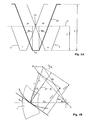
- the cutters When the inner cutter 2 is assembled with the outer cutter 3 into a single bar knife 10 with a tip width s a 0 , as is the case with the invention, the cutters must be pulled apart by 2 ⁇ ⁇ r . Either one of the two cutting edges is shifted by the total amount, or both cutting edges a and i (see FIG Fig. 1A ) shifted by half (ie by ⁇ r ). ⁇ r corresponds to the displacement of a knife in the direction of slope (27 in Fig. 1B ).
- the contours of an inner cutter 2 and an outer cutter 3 are in Fig. 1A represented by thin lines.
- the contour of the new rod 10 is shown by a thicker line.
- the knife edge for generating the convex edge is set to a smaller radius and the knife edge for generating the concave edge to a larger radius in such a way that a positive blade tip width s a 0 ⁇ 0.32 ⁇ m n is formed ( m n is average normal modulus).
- the corresponding radius change must not be radial, but must be in the direction of slope 27 (FIG. Fig. 1B ).
- the various geometric quantities are designated by an "x" for convex or a "v" for concave.
- Fig. 1A a representation is shown, from which it can be seen how two individual outer cutting a and inner cutting i can be placed together so that there is a positive peak width s a0 .
- v r w 2 - m n ⁇ z 0 2 2 ⁇ x v ⁇ ⁇ r r x .
- v r Fl x . v 2 + m n ⁇ z 0 2 2 2
- ⁇ FX is the knife edge angle for generating the convex tooth flank and ⁇ Fv the knife edge angle for generating the concave tooth flank.
- t represents the tip height of the bar blade 10 and dimensions the profile reference plane to the blade tip.
- the profile reference line is in Fig. 1A represented by the dash-dotted line 4.
- h is the blade profile height, which for practical reasons is slightly larger than the tooth profile to be produced.
- the knife profiles cross over at design point P1.
- the profile reference line 4 serves as a design variable for the design of bevel gear teeth.
- the two knives 2 and 3 have the same circle radius.
- r FLx , v the tool radii of the outer and inner diameter in the pitch direction are designated, r w stands for the cutter head nominal radius and m n for the average normal modulus.
- r x is the circle radius of the cutting edge for the convex flank and r v is the circle radius of the cutting edge for the concave flank.
- the radial ⁇ and the mean rolling position (also called roll angle) must also be ⁇ m (see Fig. 1B ) are adjusted so that the same desired mean spiral angle ⁇ m is formed on both flanks.
- Fig. 1B it can be seen that the radial ⁇ v differs from the radial ⁇ x .
- the Wälzwiegenwinkel ⁇ mx and ⁇ mv are different. When changing from a first machine setting to a second machine setting, these parameters are changed.
- ⁇ m is the mean spiral angle at the design point P1 and R m is the mean cone distance.
- a bar blade 10 preferably comes in accordance with Fig. 2A, 2B for use.
- the bar knife 10 has a shaft 11.
- the shape of the shaft 11 is chosen so that the bar blade 10 can be securely and accurately fixed in a corresponding blade groove or chamber 21 of a cutter head 20.
- the cross section of the shaft 11 may be, for example, rectangular or polygonal.
- first flank 14 A-side or flank A
- second flank 13 B-side or flank B
- top flank 15 a first flute 18, a second cutting edge 17 and a head cutting edge 16.
- the rake surface 12 intersects with the first flank 14 in a virtual cutting line which approximately corresponds to the course of the first blade 18, or which coincides exactly with the course of the first blade 18.
- the Span surface 12 intersects with the second free surface 13 in a virtual cutting line, which corresponds approximately to the course of the second cutting edge 17, or which coincides exactly with the course of the second cutting edge 17.
- the various surfaces of the bar blade 10, which form the actual blade profile, generated by grinding a rod-shaped body are provided.
- the knife profile of the bar cutter 10 in all embodiments has a special cutter head geometry (arrangement of surfaces, cutting edges, and angles) in which both the inner cutter and the outer cutter have been combined into a single bar cutter 10.
- the geometry of the bar blades 10 is preferably chosen so that when setting a first machine setting on the gear cutting machine, the first blade 18 serves as an active cutting edge, for example, to cut the convex inner flanks on the bevel gear in a continuous process.
- the second cutting edge 17 serves as an active cutting edge, for example, to cut the concave outer flanks on the same bevel gear in a continuous process, without for this purpose the cutter head 20 is recessed or a other knife head would have to be clamped.
- the first cutting edge 18 and the second cutting edge 17 are preferably arranged on a bar blade 10 in all embodiments such that the two cutting edges 17, 18 have a positive tip width (ie L1> 0 in FIG Fig. 2B ) establish.
- Fig. 2A the example of such a bar knife 10 is shown, in which the peak width is positive, ie in which a head cutting edge 16 with a length L1> 0 results in the tip region (see, for example, US Pat Fig. 2C ).
- the rake face 12 has, for example, a real point defined by the point of intersection P of the two cutting edges 17, 18 (see, eg Fig. 2D ).
- Fig. 2D represents a special case. In previous continuous methods, even a negative peak width would result, ie the peak P would then be lower in this case.
- these inner and outer blades are so in a spatial relationship to one another that in a projection of the inner and outer blades in a common plane yields a positive peak.
- FIG. 2B Further details of an embodiment of a bar cutter 10 are shown in a schematic plan view. In plan view, details of the geometry of the head portion of the bar cutter 10 can be seen, it being noted that the blades each have a slight radius of curvature, which is not shown in the schematic drawings.
- Fig. 2C is shown in a schematic view of a common rake face 12, which is bounded by two cutting edges 17, 18 and has a positive peak width.
- the rake surface 12 is preferably trapezoidal, with the two blades 17, 18 typically not having the same length or slope.
- the two cutting edges 17, 18 define an intersection point P which lies above (outside) the plane of the rake face 12.
- the rake surface 12 is limited in the upper region by a head cutting edge 16 with a cutting edge length L1.
- the head cutting edge 16 does not represent a straight line in practice.
- the edge cutting edges 17, 18 merge into the head cutting edge 16 with a radius which, in the schematic representations of FIGS. 2A to 2C not shown. Because of the curvature of the head cutting edge 16, the length of S a0 is greater than the length of L1.
- Fig. 2D is shown in a schematic view of a rake face 12 which is bounded by two cutting edges 17, 18 which do not define a positive tip width.
- this is a special case with a triangular rake surface 12, wherein the intersection P coincides with one of the three corners of the triangle.
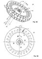
- the cutter head 20 here comprises twenty-six cutter grooves or chambers 21, which are inclined from the cutter head contact surface 25 to the cutter head end face 24 approximately in the pitch direction of the cutter head 20.
- the knife grooves or chambers 21 are opposite the circumferential direction by ⁇ ( Fig. 3B ) to obtain the most uniform clearance angle on the A side and B side of the bar blade 10.
- ⁇ Fig. 3A
- an auxiliary line HL is drawn to illustrate the inclination ⁇ .
- the dimension line 29 runs parallel to the knife head axis 28.
- Fig. 3B is a built-in bar blade 10 according Fig. 2B shown in a position I.
- the other knife grooves or chambers 21 are still unoccupied in the moment shown.
- It can be seen from this one bar knife 10 how the cutters 17, 18 would move in space if the cutter head 20 made a clockwise rotation about the axis of rotation (knife head axis 28) in the center.
- a clockwise rotation for example, with the first machine setting, the cutters 18 will cut one inside edge after the other at the bevel gear.
- a second machine setting has been set and set, the blades 17 cut one edge after the other on the bevel gear.
- the rotation ⁇ of the cutter grooves is in Fig. 3B located.
- the cutting edge 18 cuts an inner edge, while the cutting edge 17 intersects an opposite (temporary) edge. This happens, for example, when the bar blade 10 of the cutter head 20 in a Dip the blank where no gaps have been prefabricated.
- the bar blade 10 works in this case, virtually full-profile.
- the opposite provisional flank which is cut almost simultaneously with the inner flank, but does not correspond to the final outer flank of the same tooth gap.
- the outer edge is then cut only by the cutting edge 17 and finished, after the second machine setting has been specified.
- the method for milling a bevel gear can now be defined as follows. It is a continuous process, wherein a cutter head 20 (eg according to Fig. 3A, 3B ) is used, which comprises a plurality of pairs of inner cutting 18 and outer cutting 17. Depending on an inner cutter 18 and an outer cutter 17 can on a bar blade 10 (eg Fig. 2A, 2B ) may be arranged as a pair. The inner cutters 18 are arranged on a smaller circle radius than the outer cutters 17. The movements for cutting milling are carried out by a gear cutting machine so that both the bevel gear and the cutter head 20 run coupled.
- a cutter head 20 eg according to Fig. 3A, 3B
- a bar blade 10 eg Fig. 2A, 2B
- the movements for cutting milling are carried out by a gear cutting machine so that both the bevel gear and the cutter head 20 run coupled.
- a continuous cutting milling operation is performed by the gear cutting machine, wherein convex inner flanks are machined on the bevel gear by using the inner cutters 18, and wherein this first continuous cutting machining takes place with a first machine setting.
- a continuous cutting machining is performed by the gear cutting machine, wherein concave outer flanks are machined on the bevel gear by using the outer cutters 17, and wherein this second continuous machining milling is done with a second machine setting.
- the sequence of these process steps can also be the other way round. In this case, first the concave outer flanks and then the convex inner flanks would be machined.
- a first continuous cutting machining operation is performed by the gear cutting machine, wherein convex inner flanks are machined on the bevel gear by use of the inner cutters 18, and wherein this first continuous machining cut machining takes place with a first machine setting.
- a second continuous cutting milling operation is performed by the gear cutting machine, wherein concave outer flanks are machined on the bevel gear by using the outer cutters 17, and this second continuous cutting milling is done with a second machine setting.
- Per knife groove or chamber 21 are preferably two threaded holes 22 (see Fig. 3A ) is provided for fastening screws of the bar blade 10 in the peripheral surface of the cutter head 20.
- the corresponding blade head axis 28 is in Fig. 3A indicated.
- a monobloc cutter head (one-piece cutter head) is used as the cutter head 20.
- a cutter head 20 is used, in which all cutter grooves or chambers 21 have the same shape, position and inclination.
- the two different circle radii result from the geometry of the head portion of the bar blade 10.
- the knife grooves or chambers 21 have been made in all embodiments by an erosion process to make them fit.
- a bar blade 10 per blade group of the cutter head 20 is used.
- a corresponding cutter head 20 is shown. But it can also be used two bar knives per knife group.
- bar blades 10 are used whose rake angle is zero or near zero.
Description
Gegenstand der Erfindung ist ein Verfahren zum Fräsen einer Kegelradverzahnung im kontinuierlichen Fräsverfahren. Insbesondere geht es um das Fräsen einer spiralförmigen Kegelradverzahnung.The invention relates to a method for milling a bevel gear in a continuous milling process. In particular, it is about the milling of a spiral bevel gear.
Es gibt zahlreiche Verfahren zur Fertigung von Zahnrädern. Man unterscheidet bei der spanenden Herstellung von Spiralkegelrädern zwischen dem Einzelteilverfahren und dem kontinuierlichen Verfahren, das teilweise auch als kontinuierliches Teilungsverfahren bezeichnet wird.There are numerous methods of manufacturing gears. A distinction is made in the cutting production of spiral bevel gears between the single-part method and the continuous method, which is sometimes referred to as a continuous division method.
Beim kontinuierlichen Verfahren (auch Face Hobbing genannt) kommt beispielsweise ein Messerkopfwerkzeug mit gruppenweise angeordneten Innenmessern und Aussenmessern zum Einsatz, um die konvexen und konkaven Flanken eines Werkstücks zu schneiden. D.h., dass das Werkstück wird in einer Aufspannung im pausenlosen Verfahren fertig geschnitten. Das kontinuierliche Verfahren basiert auf sehr komplexen, gekoppelten Bewegungsabläufen, bei denen das Werkzeug und das zu bearbeitende Werkstück relativ zueinander eine kontinuierliche Teilungsbewegung ausführen. Die Teilungsbewegung ergibt sich aus dem koordinierten Antreiben mehrere Achsantriebe einer entsprechenden Maschine. Beim kontinuierlichen Teilverfahren sind die Drehung des Messerkopfes und die des zu bearbeitenden Werkstücks so gekoppelt, dass sich jeweils nur eine Messergruppe durch eine Zahnlücke bewegt und sich die nächste Messergruppe durch die nächste Lücke bewegt. Die Teilung erfolgt also kontinuierlich und alle Lücken werden quasi gleichzeitig erzeugt. Durch diese gekoppelten Bewegungen ergibt sich eine verlängerte Epizykloide als Flankenlängslinie auf dem Planrad des zu erzeugenden Kegelrads. Beim kontinuierlichen Verfahren stehen die Messer einer Messergruppe mit einem Phasenwinkel hintereinander, wobei sich die Schneiden der Aussen- und Innenmesser in der Projektion in eine gemeinsame Ebene überschneiden.In the case of a continuous process (also known as face hobbing), for example, a knife head tool with inner knives and outer knives arranged in groups is used to cut the convex and concave flanks of a workpiece. This means that the workpiece is cut in one clamping in the non-stop process. The continuous process is based on very complex, coupled motion sequences in which the tool and the workpiece to be machined perform a continuous pitching movement relative to each other. The pitch movement results from the coordinated driving multiple axle drives a corresponding machine. In the continuous part of the process, the rotation of the cutter head and the workpiece to be machined are coupled so that only one group of knives moves through a tooth gap and the next group of knives moves through the next gap. The division thus takes place continuously and all gaps are generated virtually simultaneously. Due to these coupled movements, an elongated epicycloid results as a flank longitudinal line on the face gear of the bevel gear to be generated. In the continuous process, the knives of a knife group are at a phase angle one behind the other, with the cutting edges of the outer and inner knives overlapping in the projection in a common plane.
Beim teilenden Verfahren (auch Einzelteilverfahren oder Face Milling genannt) wird eine Zahnlücke bearbeitet, dann erfolgt eine relative Verschiebungsbewegung zum Herausfahren des Werkzeugs aus einer Zahnlücke und eine sogenannte Teilungsbewegung (Teilungsdrehung), bei der sich das Werkstück relativ zum Werkzeug dreht, bevor dann die nächste Zahnlücke bearbeitet wird. Es wird somit Schritt für Schritt ein Zahnrad gefertigt. Beim Einzelteilverfahren kann ein erster Messerkopf mit Innenschneidern und Aussenschneidern eingesetzt werden, um Innenflanken (konvexe Zahnflanken) am Werkstück zu schneiden und Aussenflanken vorbereitend zu bearbeiten. Die Aussenschneider erzeugen nicht die endgültige Geometrie der Aussenflanken. Dann kann der erste Messerkopf gegen einen zweiten Messerkopf ausgetauscht werden, der mit Aussenschneidern bestückt ist, um die Aussenflanken (konkave Zahnflanken) am Werkstück fertig zu schneiden. Diese Vorgehensweise wird auch als einzelseitiges Schneiden bezeichnet. Die Schneiden der Werkzeuge sind kreisförmig angeordnet (z.B. bei einem Stirnmesserkopf) und die Flankenlinien, die am Werkstück erzeugt werden, haben daher die Form eines Kreisbogens.In the dividing method (also referred to as single part method or face milling), a tooth gap is machined, then a relative displacement movement to move out of the tool from a tooth gap and a so-called pitching (pitch rotation), in which the workpiece rotates relative to the tool, before then the next Tooth gap is processed. It is thus produced step by step a gear. In the single-part method, a first knife head with inner cutters and outer cutters can be used to cut inner flanks (convex tooth flanks) on the workpiece and to prepare outer flanks. The outer cutters do not produce the final geometry of the outer flanks. Then the first knife head can be exchanged for a second knife head equipped with outer cutters to cut the outer flanks (concave tooth flanks) on the workpiece. This procedure is also referred to as single-sided cutting. The cutting edges of the tools are arranged in a circle (e.g., in a face cutter head) and the flank lines created on the workpiece are therefore in the form of a circular arc.
Es findet beim beschriebenen Einzelteilverfahren ein Messerkopfwechsel statt, was einerseits zu einer Verlängerung der gesamten Bearbeitungsdauer führt und was andererseits Ungenauigkeiten mit sich bringen kann, da jedes Umspannen oder Neuaufspannen zu kleinen Abweichungen von der Idealposition führen kann. Das teilende Verfahren hat außerdem den Nachteil, dass es zu sogenannten Teilungsfehlern kommt. Es ist ein Vorteil des einzelseitigen Einzelteilverfahrens mit zwei separaten Messerköpfen, dass beide Zahnflanken quasi unabhängig voneinander optimiert werden können.There is a cutter head change in the described item process, which on the one hand leads to an extension of the total processing time and what on the other hand can bring inaccuracies, since each re-clamping or rebuilding can lead to small deviations from the ideal position. The dividing method also has the disadvantage that so-called division errors occur. It is an advantage of the single-sided component method with two separate cutter heads that both tooth flanks can be optimized virtually independently of each other.
Das sogenannte Completing-Verfahren ist ein spezielles Einzelteilverfahren, das vorzugsweise in der Grossserie eingesetzt wird. Das Tellerrad und das Ritzel werden beim Completing-Verfahren im Zweiflankenschnitt komplett fertig bearbeitet. Gegenüber anderen Einzelteilverfahren zeichnet sich das Completing-Verfahren durch höhere Produktivität (doppelte Zerspanleistung) aus, jedoch ist eine Veränderung der Flankenform schwieriger, da Veränderungen der Maschinenkinematik, wie bei allen Verfahren mit Zweiflankenschnitt, immer Einfluss auf beide Flanken haben. Es ist somit ein Nachteil des Completing-Verfahrens, dass sich bei einer Änderung einer Flanke mittels der Maschinenkinematik stets auch eine Änderung der anderen Flanke ergibt. Änderungen sind daher nur dann möglich, wenn sie "zweiflankenschnittverträglich" sind.The so-called completing process is a special single-part process, which is preferably used in large-scale production. The crown wheel and the pinion are completely finished during the completion process in the two-flute cut. Compared to other single-part processes, the completing process is characterized by higher productivity (double cutting performance), but a change in the edge shape is more difficult since changes in the machine kinematics, as in all two-flute cutting processes, always have an influence on both flanks. It is thus a disadvantage of the completing method that always results in a change of an edge by means of machine kinematics, a change in the other edge. Changes are therefore only possible if they are "zweilankenschnittverträglich".
Entsprechend unterscheidet man im Wesentlichen auch zwischen Maschinen, die im teilenden Verfahren arbeiten und Maschinen, die kontinuierlich arbeiten.Accordingly, a distinction is essentially made between machines that work in the dividing method and machines that work continuously.
Als nächstliegender Stand der Technik wird das sogenannte Multicut- oder Oerlikon Multicut-Verfahren bezeichnet, das zum Beispiel in dem Dokument "
Aufgabe der vorliegenden Erfindung ist es, ein Verfahren zum Fräsen der Zahnflanken eines Zahnrades bereitzustellen, das ein gutes Tragbild oder gute Oberflächeneigenschaften der Zahnflanken gewährleistet und das sich durch eine gute Produktivität auszeichnet. Die Reduktion der Bearbeitungszeit pro Zahnrad ist ein Hauptziel der Erfindung.Object of the present invention is to provide a method for milling the tooth flanks of a gear, which ensures a good contact pattern or good surface properties of the tooth flanks and which is characterized by a good productivity. The reduction of the processing time per gear is a main object of the invention.
Diese Aufgabe wird gemäß der vorliegenden Erfindung durch ein Verfahren gelöst, das ansatzweise mit dem Semi-Completing Verfahren vergleichbar ist, das zum Schleifen im Einzelteilverfahren von im Zyklo-Palloid-Verfahren vorgefrästen Verzahnungen eingesetzt wird.This object is achieved according to the present invention by a method that is somewhat similar to the semi-completing method, which is used for grinding in the single-part method of teeth pre-milled in the cyclo-palloid method.
Kennzeichnend für das Verfahren der Erfindung ist, dass die beiden Flanken (d.h. die konvexen Innenflanken und die konkaven Aussenflanken) des Kegelrades mit getrennten Maschineneinstellungen, jedoch mit demselben Werkzeug kontinuierlich gefräst werden. Hierzu müssen jedoch die für die Bearbeitung der konkaven und konvexen Flanke erforderlichen Werkzeugradien auf einem gemeinsamen Messerkopf untergebracht werden. Die Innenschneiden zur fräsenden Bearbeitung der konvexen Innenflanken am Kegelwerkrad sitzen auf einem ersten Flugkreisradius. Die Aussenschneiden zur fräsenden Bearbeitung der konkaven Aussenflanken am Kegelwerkrad sitzen auf einem zweiten Flugkreisradius. Der erste Flugkreisradius ist kleiner als der zweite Flugkreisradius. Durch die Vorgabe unterschiedlicher Flugkreisradien, können sowohl die Innenschneiden als auch die Aussenschneiden auf ein und demselben Messerkopf, und vorzugsweise sogar auf ein und demselben Stabmesser, untergebracht werden. Da der Flugkreisradius jedoch mit dem Folgewinkel zusammenhängt, müssen die Maschineneinstellungen angepasst werden.Characteristic of the method of the invention is that the two flanks (i.e., the convex inner flanks and the concave outer flanks) of the bevel gear are milled continuously with separate machine settings, but with the same tool. For this purpose, however, the tool radii necessary for the machining of the concave and convex flank must be accommodated on a common cutter head. The internal cutting edges for milling the convex inner flanks on the bevel gear wheel are located on a first circle radius. The outer cutting edges for milling the concave outer flanks on the bevel gear wheel are located on a second circle radius. The first circle radius is smaller than the second circle radius. By specifying different circle radii, both the inner and the outer cutters can be accommodated on the same cutter head, and preferably even on the same bar cutter. However, since the circle radius is related to the following angle, the machine settings must be adjusted.
Zum Beispiel führt eine Änderung des Winkels zwischen Innen- und Aussenmesser (dieser Winkel wird Folgewinkel genannt) beim kontinuierlichen Verfahren zu einer Veränderung der Zahndicke, während sie beim Einzelteilverfahren keine Auswirkungen hat. Es müssen daher beim erfindungsgemässen Verfahren Modifikationen der Maschineneinstellungen vorgenommen werden, um Veränderungen der Zahndicke (Zahndickenfehler), der Spiralwinkel (Spiralwinkelfehler) und anderer Aspekte zu kompensieren oder zu korrigieren.For example, a change in the angle between the inner and outer blades (this angle is called the following angle) in the continuous process leads to a change in tooth thickness, while it has no effect in the single part process. It must therefore be made in the inventive method modifications of the machine settings to compensate for changes in tooth thickness (tooth thickness error), the spiral angle (spiral angle error) and other aspects or correct.
Im Unterschied zum erwähnten Multicut-Verfahren werden gemäss Erfindung Kegelradritzel und Tellerrad einzelseitig gefertigt und diese jeweils mit einem Messerkopf mit beidseitigen Schneidern oder mit Innen- und Aussenschneidern.In contrast to the mentioned multicut method Kegelradritzel and ring gear are manufactured on one side according to the invention and this each with a cutter head with two-sided tailors or with inner and outer cutters.
Gemäss Erfindung kommt ein Messerkopf zum Einsatz, der so ausgelegt und mit Messern bestückt ist, dass der Flugkreisradius der Aussenmesser grösser ist als der Flugkreisradius der Innenmesser. D.h. es werden unterschiedliche Flugkreisradien vorgesehen.According to the invention, a knife head is used, which is designed and equipped with knives such that the circle radius of the outer knife is greater than the circle radius of the inner knife. That There are different radius of the radii are provided.
Gemäss Erfindung werden die konvexen und konkaven Flanken des Kegelrades mit getrennten Maschineneinstellungen gefräst.According to the invention, the convex and concave flanks of the bevel gear are milled with separate machine settings.
Es geht gemäss Erfindung also um ein kontinuierliches Semi-Completing Fräsverfahren, d.h. um ein Verfahren, bei dem Aspekte des Semi-Completings auf ein kontinuierliches Fräsverfahren angewendet werden.It is therefore according to the invention to a continuous semi-completing milling process, i. a method in which aspects of semi-completing are applied to a continuous milling process.
Gemäss Erfindung müssen jedoch, wie erwähnt, Modifikationen der Maschineneinstellungen vorgenommen werden, da sich das Semi-Completing Einzelteilverfahren nicht 1:1 übertragen lässt. Diese Modifikationen sind erforderlich, um das Tragbild ungefähr in der Zahnmitte der zu fertigenden Zähne zu positionieren.According to the invention, however, as mentioned, modifications of the machine settings must be made because the semi-completing item method can not be transferred 1: 1. These modifications are required to position the wear pattern approximately in the tooth center of the teeth to be manufactured.
Es ist ein Vorteil der Erfindung, dass weder das Werkzeug gewechselt (umgespannt) werden muss, noch dass eine Zweispindelmaschine mit zwei verschiedenen Werkzeugen eingesetzt werden muss.It is an advantage of the invention that neither the tool needs to be changed (re-clamped), nor that a two-spindle machine with two different tools must be used.
Das erfindungsgemässe Verfahren kann sowohl als Trocken- oder Nassbearbeitung durchgeführt werden.The inventive method can be carried out both as dry or wet processing.
Weitere Einzelheiten und Vorteile der Erfindung werden im Folgenden anhand von Ausführungsbeispielen und mit Bezug auf die Zeichnung beschrieben.
- FIG. 1A
- zeigt eine schematische Darstellung zur Kombination eines Innenmessers mit einem Aussenmesser zu einem Stabmesser mit Schneiden, die eine positive Spitzenweite aufweisen;
- FIG. 1B
- zeigt weitere Details der geometrischen Herleitung;
- FIG. 2A
- zeigt eine perspektivische Ansicht eines Stabmessers in einer ersten Ausführungsform;
- FIG. 2B
- zeigt eine Draufsicht des Stabmessers nach
Fig. 2A ; - FIG. 2C
- zeigt eine stark schematisierte Ansicht einer Spanfläche eines erfindungsgemässen Stabmessers mit positiver Spitzenweite;
- FIG. 2D
- zeigt eine stark schematisierte Ansicht einer Spanfläche eines nicht erfindungsgemässen Stabmessers mit negativer Spitzenweite;
- FIG. 3A
- zeigt eine perspektivische Ansicht eines Messerkopfs in einer ersten Ausführungsform;
- FIG. 3B
- zeigt eine Draufsicht des Messerkopfs nach
Fig. 3A .
- FIG. 1A
- shows a schematic representation of the combination of an inner diameter with an outer diameter to a bar knife with cutting edges, which have a positive tip width;
- FIG. 1B
- shows further details of the geometric derivation;
- FIG. 2A
- shows a perspective view of a bar blade in a first embodiment;
- FIG. 2 B
- shows a top view of the bar blade after
Fig. 2A ; - FIG. 2C
- shows a highly schematic view of a rake face of an inventive bar knife with positive peak width;
- FIG. 2D
- shows a highly schematic view of a rake face of a not according to the invention bar knife with negative peak width;
- FIG. 3A
- shows a perspective view of a cutter head in a first embodiment;
- FIG. 3B
- shows a top view of the cutter head after
Fig. 3A ,
Im Zusammenhang mit der vorliegenden Beschreibung werden Begriffe verwendet, die auch in einschlägigen Publikationen und Patenten Verwendung finden. Es sei jedoch angemerkt, dass die Verwendung dieser Begriffe lediglich dem besseren Verständnis dienen soll. Der erfinderische Gedanke und der Schutzumfang der Patentansprüche soll durch die spezifische Wahl der Begriffe nicht in der Auslegung eingeschränkt werden. Die Erfindung lässt sich ohne weiteres auf andere Begriffssysteme und/oder Fachgebiete übertragen. In anderen Fachgebieten sind die Begriffe sinngemäß anzuwenden.In the context of the present description, terms are used which are also used in relevant publications and patents. It should be noted, however, that the use of these terms is for the convenience of understanding only. The inventive idea and the scope of the claims should not be limited by the specific choice of the terms in the interpretation. The invention can be readily applied to other conceptual systems and / or fields. In other fields the terms are to be applied mutatis mutandis.
Beim vorbekannten kontinuierlichen Verfahren werden beide Zahnflanken mit dem gleichen Werkzeugradius (abgesehen von Korrekturen zur Balligkeitserzeugung etc.) bearbeitet. Die Hauptschneiden der entsprechenden Innen- und Außenschneider kreuzen sich in der Teilebene. Der Innenschneider folgt dem Außenschneider mit Winkelabstand π / z0. z0 ist die Gangzahl.In the prior art continuous process, both tooth flanks are machined with the same tool radius (apart from corrections for crowning, etc.). The main cutting edges of the corresponding inner and outer cutters intersect in the part plane. The inner cutter follows the outer cutter with angular distance π / z 0 . z 0 is the number of gears.
Wenn der Innenschneider 2 mit dem Außenschneider 3 zu einem einzigen Stabmesser 10 mit Spitzenweite s a0 zusammengefügt werden, wie dies bei der Erfindung der Fall ist, müssen die Schneiden um 2·Δr auseinander gezogen werden. Entweder wird eine der beiden Schneiden um den Gesamtbetrag verschoben, oder es werden beide Schneiden a und i (siehe
In diesem Fall wird die Messerflanke zur Erzeugung der konvexen Flanke auf einen kleineren Radius und die Messerflanke zur Erzeugung der konkaven Flanke auf einen größeren Radius gesetzt und zwar so, dass eine positive Messerspitzenbreite s a0≈0.32·mn entsteht (mn ist das mittlere Normalmodul). Die entsprechende Radienänderung darf nicht radial, sondern muss in Steigungsrichtung 27 (
In 


α FX ist der Messerflankenwinkel zur Erzeugung der konvexen Zahnflanke und α Fv der Messerflankenwinkel zur Erzeugung der konkaven Zahnflanke. t stellt die Spitzenhöhe des Stabmessers 10 dar und bemasst die Profilbezugsebene zur Messerspitze. Die Profilbezugslinie ist in
Mit dem geänderten Radius müssen auch die Radiale ϕ und die mittlere Wälzstellung (auch Wälzwiegenwinkel genannt) α m (siehe
In 
![]()

vx und vv sind geometrische Hilfsgrössen zur Herleitung, βm ist der mittlere Spiralwinkel im Auslegungspunkt P1 und Rm ist die mittlere Teilkegellänge.In ![]()
v x and v v are geometric auxiliary variables for the derivation, β m is the mean spiral angle at the design point P1 and R m is the mean cone distance.
Beim Umschalten von der Bearbeitung der konvexen Zahnflanke auf die Bearbeitung der konkaven Flanke , d.h. beim Umstellen von der ersten auf die zweite Maschineneinstellung, muss das Planrad um eine halbe Teilung verdreht werden, und das Werkstück (Kegelwerkrad) muss entsprechend dem Verhältnis der Planradzähnezahl Zp zur zugehörigen Zähnezahl z des Werkrades verdreht werden. Diese Verdrehung aβ ergibt sich aus der folgenden Gleichung: 
Gemäss Erfindung kommt vorzugsweise ein Stabmesser 10 gemäss
Im Kopfbereich des Stabmessers 10 befinden sich eine erste Freifläche 14 (A-Seite oder Freifläche A), eine zweite Freifläche 13 (B-Seite oder Freifläche B), eine (gemeinsame) Spanfläche 12, eine Kopffreifläche 15, eine erste Schneide 18, eine zweite Schneide 17 und eine Kopfschneide 16.In the head area of the
Die Spanfläche 12 schneidet sich mit der ersten Freifläche 14 in einer virtuellen Schnittlinie, die in etwa dem Verlauf der ersten Schneide 18 entspricht, oder die genau mit dem Verlauf der ersten Schneide 18 übereinstimmt. Die Spanfläche 12 schneidet sich mit der zweiten Freifläche 13 in einer virtuellen Schnittlinie, die in etwa dem Verlauf der zweiten Schneide 17 entspricht, oder die genau mit dem Verlauf der zweiten Schneide 17 übereinstimmt.The
Vorzugsweise werden bei allen Ausführungsformen die verschiedenen Flächen des Stabmessers 10, die das eigentliche Messerprofil bilden, durch Schleifen eines stabförmigen Grundkörpers erzeugt.Preferably, in all embodiments, the various surfaces of the
Vorzugsweise hat das Messerprofil des Stabmessers 10 bei allen Ausführungsformen eine spezielle Messerkopfgeometrie (Anordnung der Flächen, Schneiden, und Winkel), bei der sowohl das Innenmesser als auch das Aussenmesser in ein einziges Stabmesser 10 vereinigt wurde. Die Geometrie der Stabmesser 10 ist vorzugsweise so gewählt, dass bei der Vorgabe einer ersten Maschineneinstellung auf der Verzahnmaschine die erste Schneide 18 als aktive Schneidkante dient, um zum Beispiel die konvexen Innenflanken am Kegelwerkrad im kontinuierlichen Verfahren zu schneiden. Bei der Vorgabe einer zweiten Maschineneinstellung, die sich von der ersten Maschineneinstellung unterscheidet, dient die zweite Schneide 17 als aktive Schneidkante, um zum Beispiel die konkaven Aussenflanken am selben Kegelwerkrad im kontinuierlichen Verfahren zu schneiden, ohne dass zu diesem Zweck der Messerkopf 20 umgespannt oder ein anderer Messerkopf aufgespannt werden müsste.Preferably, the knife profile of the
Die erste Schneide 18 und die zweite Schneide 17 sind vorzugsweise bei allen Ausführungsformen so an einem Stabmesser 10 angeordnet, dass die beiden Schneiden 17, 18 eine positive Spitzenweite (d.h. L1 > 0 in
Bei Ausführungsformen der Erfindung, die mit getrennten Innen- und Außenmesser arbeiten (d.h. wenn Innen- und Außenmesser mit einem Folgewinkel zueinander stehen), stehen diese Innen- und Außenmesser so zueinander in einem räumlichen Bezug, dass sich bei einer Projektion der Innen- und Außenmesser in eine gemeinsame Ebene eine positive Spitzenweite ergibt.In embodiments of the invention which operate with separate inner and outer blades (ie, when inner and outer blades are at a follow angle to each other), these inner and outer blades are so in a spatial relationship to one another that in a projection of the inner and outer blades in a common plane yields a positive peak.
In
In
In
Dadurch, dass eine Stabmessergeometrie mit positiver Spitzenweite gewählt wird, lassen sich die Aussenschneide 17 und die Innenschneide 18 so an einem gemeinsamen Stabmesser 10 unterbringen, dass die konvexe Innenflanke mit einer ersten Maschineneinstellung und die konkave Aussenflanke am Kegelwerkrad unabhängig davon mit einer zweiten Maschineneinstellung geschnitten werden können, ohne dass eine der Schneiden 17, 18 Fehler oder Ungenauigkeiten beim Schneiden der jeweils anderen Flanke verursachen würde.Characterized in that a bar geometry is selected with positive peak width, let the
Eine Mehrzahl (hier N=26) solcher Stabmesser 10 wird in einen Messerkopf 20 eingebracht, der in den
In
Je nach Wahl der Maschineneinstellungen und der konkreten Geometrie des Stabmessers 10, kann es sein, dass bei der ersten Maschineneinstellung die Schneide 18 eine Innenflanke schneidet, während die Schneide 17 eine gegenüberliegende (provisorische) Flanke schneidet. Das geschieht zum Beispiel dann, wenn die Stabmesser 10 des Messerkopfs 20 in einen Rohling tauchen, an dem keine Zahnlücken vorgefertigt wurden. Das Stabmesser 10 arbeitet in diesem Fall quasi vollprofilig. Die gegenüberliegende provisorische Flanke, die quasi zeitgleich mit der Innenflanke geschnitten wird, entspricht aber nicht der endgültigen Aussenflanke derselben Zahnlücke. Die Aussenflanke wird dann erst durch die Schneide 17 geschnitten und fertig bearbeitet, nachdem die zweite Maschineneinstellung vorgegeben wurde.Depending on the choice of machine settings and the specific geometry of the
Das Verfahren zum Fräsen einer Kegelradverzahnung kann nun wie folgt definiert werden. Es handelt sich um ein kontinuierliches Verfahren, wobei ein Messerkopf 20 (z.B. gemäss
Gemäss Erfindung wird eine kontinuierliche spanabhebende Fräsbearbeitung durch die Verzahnungsmaschine ausgeführt, wobei konvexe Innenflanken am Kegelwerkrad durch Einsatz der Innenschneiden 18 bearbeitet werden, und wobei diese erste kontinuierliche spanabhebende Fräsbearbeitung mit einer ersten Maschineneinstellung erfolgt. Dann wird eine kontinuierliche spanabhebende Fräsbearbeitung durch die Verzahnungsmaschine ausgeführt, wobei konkave Aussenflanken am Kegelwerkrad durch Einsatz der Aussenschneiden 17 bearbeitet werden, und wobei diese zweite kontinuierliche spanabhebende Fräsbearbeitung mit einer zweiten Maschineneinstellung erfolgt. Die Reihenfolge dieser Verfahrensschritte kann aber auch andersherum sein. In diesem Fall würden zuerst die konkaven Aussenflanken und dann anschliessend die konvexen Innenflanken bearbeitet.According to the invention, a continuous cutting milling operation is performed by the gear cutting machine, wherein convex inner flanks are machined on the bevel gear by using the
An dieser Stelle sei nochmals darauf verwiesen, dass auch Ausführungsformen möglich sind, bei denen die Innenschneiden und Aussenschneiden auf getrennten Stabmessern, die mit einem Folgewinkel aufeinander folgen, angeordnet sein können.At this point it should be pointed out again that also embodiments are possible in which the inner cutting and Outer cutting on separate bar knives, which follow one another with a following angle, can be arranged.
Es wird eine erste kontinuierliche spanabhebende Fräsbearbeitung durch die Verzahnungsmaschine ausgeführt, wobei konvexe Innenflanken am Kegelwerkrad durch Einsatz der Innenschneiden 18 bearbeitet werden, und wobei diese erste kontinuierliche spanabhebende Fräsbearbeitung mit einer ersten Maschineneinstellung erfolgt. Dann wird eine zweite kontinuierliche spanabhebende Fräsbearbeitung durch die Verzahnungsmaschine ausgeführt, wobei konkave Aussenflanken am Kegelwerkrad durch Einsatz der Aussenschneiden 17 bearbeitet werden, und wobei diese zweite kontinuierliche spanabhebende Fräsbearbeitung mit einer zweiten Maschineneinstellung erfolgt.A first continuous cutting machining operation is performed by the gear cutting machine, wherein convex inner flanks are machined on the bevel gear by use of the
Pro Messernut oder -kammer 21 sind vorzugsweise zwei Gewindebohrungen 22 (siehe
Vorzugsweise kommt bei allen Ausführungsformen ein Monoblock-Messerkopf (einteiliger Messerkopf) als Messerkopf 20 zum Einsatz.Preferably, in all embodiments, a monobloc cutter head (one-piece cutter head) is used as the
Vorzugsweise kommt bei allen Ausführungsformen ein Messerkopf 20 zum Einsatz, bei dem alle Messernuten oder -kammern 21 dieselbe Form, Position und Neigung aufweisen. Die beiden unterschiedlichen Flugkreisradien ergeben sich durch die Geometrie des Kopfbereichs der Stabmesser 10. Durch die jeweiligen Maschineneinstellungen werden die jeweils aktiven Schneiden (z.B. die Schneiden 18 für das Fertigen der Innenflanken und die Schneiden 17 für das Fertigen der Aussenflanken) positioniert und durch den Werkstoff des Kegelwerkrads geführt.Preferably, in all embodiments, a
Vorzugsweise wurden die Messernuten oder -kammern 21 bei allen Ausführungsformen mittels eines Erosionsverfahrens hergestellt, um sie passgenau zu machen.Preferably, the knife grooves or
Vorzugsweise kommt bei allen Ausführungsformen ein Stabmesser 10 pro Messergruppe des Messerkopfs 20 zum Einsatz. In den
Vorzugsweise kommen bei allen Ausführungsformen Stabmesser 10 zum Einsatz, deren Spanwinkel Null oder nahe Null ist.Preferably, in all embodiments,
Claims (9)
- A method for milling a bevel gear toothing in a continuous method, wherein a milling head (20) is used which comprises several pairs of inner cutting edges (18) and outer cutting edges (17), wherein the inner cutting edges (18) are arranged on a smaller flight circle radius than the outer cutting edges (17), and wherein movements for cutting by milling are performed by a gear cutting machine in such a way that both the bevel gear workpiece and also the milling head (20) run in a coupled manner, characterized by the following steps:- performing continuous cutting by milling by the gear cutting machine, wherein convex inner flanks on the bevel gear workpiece are machined by using the inner cutting edges (18), and wherein sthis first continuous cutting by milling occurs with a first machine setting;- performing continuous cutting by milling by the gear cutting machine, wherein concave outer flanks on the bevel gear workpiece are machined by using the outer cutting edges (17), and wherein this second continuous cutting by milling occurs with a second machine setting,wherein the convex inner flanks and the concave outer flanks of the bevel gear are continuously milled with separate machine settings, but with the same tool.
- A method according to claim 1, characterized in that the milling head (20) is provided with several bar cutters (10), wherein each bar cutter (10) has a head geometry which comprises a first free surface (14), a second free surface (13) and a common cutting surface (12) disposed between the two free surfaces, wherein an inner cutting edge (18) is situated in the region of a virtual line of intersection which is obtained from the section of the first free surface (14) and the cutting surface (12), and wherein an outer cutting edge (17) is situated in the region of a virtual line of intersection which is obtained from the section of the second free surface (13) and the cutting surface (12).
- A method according to claim 1 or 2, characterized in that the milling head (20) is provided with several bar cutters (10), wherein one respective pair of inner cutting edges (18) and outer cutting edges (17) is arranged on each of the bar cutters (10), and wherein the inner cutting edge (18) and the outer cutting edge (17) of one pair do not intersect in the cutting surface (12) of the bar blade (10) in a projection in a plane of a cutting surface (12) of the bar cutter (10).
- A method according to claim 1, 2 or 3, characterized in that one respective pair of inner cutting edge (18) and outer cutting edge (17) forms a positive tip width.
- A method according to one of the preceding claims, characterized in that the bevel gear toothing is finally cut in the continuous milling process in clamping of the bevel gear workpiece in a continuous method, wherein a changeover is performed from the first machine setting to the second machine setting during a short interruption.
- A method according to one of the claims 1 to 5, characterized in that during the change from the first machine setting to the second machine setting- the virtual crown gear is twisted by half a pitch, and- the bevel gear workpiece is twisted according to the ratio of the associated number of gear teeth.
- A method according to one of the claims 1 to 5, characterized in that during the change from the first machine setting to the second machine setting a change is carried out from a first hobbing cradle angle (a mx ) to a second hobbing cradle angle (a mv ) and a change from a first radial (ϕ v ) to a second radial (ϕ x ).
- A method according to one of the claims 1 to 7, characterized in that a modification of the machine setting is performed in order to produce a contact pattern on the tooth flanks which is situated approximately in the middle of the tooth.
- A method according to one of the claims 1 to 8, characterized in that the milling method concerns a continuously dividing milling method in which both the crown wheel and also the pinion are hobbed.
Priority Applications (6)
| Application Number | Priority Date | Filing Date | Title |
|---|---|---|---|
| EP10171235.4A EP2412467B1 (en) | 2010-07-29 | 2010-07-29 | Method for machining bevelled wheel cogging in a continuous machining method |
| MX2011007773A MX2011007773A (en) | 2010-07-29 | 2011-07-21 | Method and system for milling a bevel gear tooth system in a continuous milling process. |
| CN201110212623.1A CN102398087B (en) | 2010-07-29 | 2011-07-27 | Method for machining bevelled wheel cogging in a continuous machining method |
| JP2011165794A JP5444296B2 (en) | 2010-07-29 | 2011-07-28 | Method for cutting a bevel gear tooth system in a continuous milling process |
| US13/194,045 US8882414B2 (en) | 2010-07-29 | 2011-07-29 | Method and system for milling a bevel gear tooth system in a continuous miling process |
| KR1020110076011A KR101900100B1 (en) | 2010-07-29 | 2011-07-29 | Method for milling a bevel gear tooth system in the continuous milling process |
Applications Claiming Priority (1)
| Application Number | Priority Date | Filing Date | Title |
|---|---|---|---|
| EP10171235.4A EP2412467B1 (en) | 2010-07-29 | 2010-07-29 | Method for machining bevelled wheel cogging in a continuous machining method |
Publications (2)
| Publication Number | Publication Date |
|---|---|
| EP2412467A1 EP2412467A1 (en) | 2012-02-01 |
| EP2412467B1 true EP2412467B1 (en) | 2014-01-08 |
Family
ID=43016104
Family Applications (1)
| Application Number | Title | Priority Date | Filing Date |
|---|---|---|---|
| EP10171235.4A Active EP2412467B1 (en) | 2010-07-29 | 2010-07-29 | Method for machining bevelled wheel cogging in a continuous machining method |
Country Status (6)
| Country | Link |
|---|---|
| US (1) | US8882414B2 (en) |
| EP (1) | EP2412467B1 (en) |
| JP (1) | JP5444296B2 (en) |
| KR (1) | KR101900100B1 (en) |
| CN (1) | CN102398087B (en) |
| MX (1) | MX2011007773A (en) |
Families Citing this family (13)
| Publication number | Priority date | Publication date | Assignee | Title |
|---|---|---|---|---|
| PL2181789T3 (en) * | 2008-10-30 | 2011-11-30 | Klingelnberg Ag | Universally usable bar blade cutter head and use of same |
| CN103008795A (en) * | 2012-12-11 | 2013-04-03 | 浙江晨龙锯床股份有限公司 | Rack sawing, drilling and milling unit |
| US10016825B2 (en) * | 2013-09-12 | 2018-07-10 | The Gleason Works | Internal bevel gear |
| US9608739B2 (en) * | 2013-10-15 | 2017-03-28 | Visteon Global Technologies, Inc. | System and method for a blended signal |
| DE102015104500A1 (en) * | 2015-03-25 | 2016-09-29 | Profilator Gmbh & Co. Kg | Method and device for gear cutting of gears by skiving |
| US20180243849A1 (en) * | 2015-09-21 | 2018-08-30 | The Gleason Works | Method and tool for manufacturing spiral tooth face couplings |
| CN108602145B (en) * | 2016-02-01 | 2021-04-09 | 格里森工场 | Single-blade bevel gear cutting tool |
| EP3287222A1 (en) * | 2016-08-23 | 2018-02-28 | Klingelnberg AG | Method for processing the tooth flanks of plan coupling workpieces in semi-completing method |
| EP3287221B1 (en) * | 2016-08-23 | 2019-04-24 | Klingelnberg AG | Method for processing the tooth flanks of plane coupling workpieces in semi-completing single part method |
| DE102017009924B4 (en) * | 2017-10-25 | 2021-06-17 | Klingelnberg Gmbh | Process for machining bevel gear workpieces |
| EP3511100B1 (en) * | 2018-01-15 | 2020-12-09 | Klingelnberg AG | Method for processing bevel gear workpieces |
| CN111687493B (en) * | 2020-06-08 | 2021-05-28 | 西安交通大学 | Variable tool path machining method for cycloidal-tooth bevel gear based on integral cutter head |
| CN112122714B (en) * | 2020-10-14 | 2023-01-31 | 天津大学 | Fly cutter for machining curve face gear and machining and using method thereof |
Family Cites Families (23)
| Publication number | Priority date | Publication date | Assignee | Title |
|---|---|---|---|---|
| US1788639A (en) * | 1928-03-22 | 1931-01-13 | Harold E Stonebraker | Method of cutting curved-tooth gears |
| US1969843A (en) * | 1931-01-02 | 1934-08-14 | Gleason Works | Cutter for and method of cutting gears |
| US2324182A (en) * | 1937-12-31 | 1943-07-13 | Gleason Works | Method of producing gears |
| US2334366A (en) * | 1942-05-22 | 1943-11-16 | Gleason Works | Method of producing face clutches |
| CH317210A (en) * | 1951-10-06 | 1956-11-15 | Klingelnberg Soehne Ferd | Method and machine for the production of bevel gears with tooth flank longitudinal lines curved according to cyclic curves |
| US2978964A (en) * | 1954-12-02 | 1961-04-11 | Wildhaber Ernest | Method and apparatus for cutting gears |
| US3222990A (en) * | 1961-03-25 | 1965-12-14 | Fred Klingelnberg Sohne W | Method of separately roughing and finishing bevel gears |
| CH417284A (en) * | 1963-01-07 | 1966-07-15 | Oerlikon Buehrle Holding Ag | Method and cutter head pair for longitudinally crowned toothing of a bevel gear or hypoid gear pair with longitudinally curved teeth |
| US5000632A (en) * | 1989-09-04 | 1991-03-19 | Werkzeugmaschinenfabrik Oerlikon-Buhrle Ag | Duplex method of manufacturing a generated spiral-toothed bevel gear of a bevel-gear or hypoid-gear drive |
| DE19646189C2 (en) * | 1996-11-08 | 1999-08-26 | Klingelnberg Soehne Gmbh | Machine for producing bevel gears with curved teeth |
| US5895180A (en) * | 1997-09-05 | 1999-04-20 | The Gleason Works | Method of determining cutting blade positional errors in face hobbing cutters |
| BR9906311A (en) * | 1998-04-01 | 2000-07-11 | Mitsubishi Heavy Ind Ltd | Process and apparatus for milling gears to generate a bevel gear, and spiral bevel gear tool |
| AU3548800A (en) * | 1999-12-01 | 2001-06-12 | Lambert Ag | Method for grinding straight toothed conical gear wheels |
| JP2002273623A (en) * | 2001-03-16 | 2002-09-25 | Komatsu Ltd | Spiral bevel gear manufacturing device and spiral bevel gear manufacturing method |
| US6536999B1 (en) * | 2001-09-12 | 2003-03-25 | Torque-Traction Technologies, Inc. | Gear cutter blade |
| JP3717447B2 (en) | 2001-11-28 | 2005-11-16 | 旭化成せんい株式会社 | Polytrimethylene terephthalate composition |
| RU2306209C2 (en) * | 2003-05-22 | 2007-09-20 | КЛИНГЕЛЬНБЕРГ ГмбХ | Method for milling spiral cone gear wheels and hypoid gear wheels, finely sharpened cutter for performing the same and method of using such cutter |
| DE102005058536B4 (en) * | 2004-12-16 | 2010-07-08 | The Gleason Works | Cutting tool system, in particular for splining bevel gears in the single-part method |
| US8267624B2 (en) * | 2005-06-27 | 2012-09-18 | The Gleason Works | Full point width cutting blades |
| CN201026542Y (en) * | 2007-04-27 | 2008-02-27 | 哈尔滨工具厂 | Arcuated cusp, gear milling cutter |
| PL2181789T3 (en) * | 2008-10-30 | 2011-11-30 | Klingelnberg Ag | Universally usable bar blade cutter head and use of same |
| CN201500830U (en) * | 2009-10-23 | 2010-06-09 | 哈尔滨工具厂 | Hard-alloy soft tooth surface arc-shaped tooth bevel gear milling cutter |
| CN101733483B (en) * | 2009-12-10 | 2012-10-03 | 吉林大学 | Spiral bevel gear cutting machine tool and gear cutting method |
-
2010
- 2010-07-29 EP EP10171235.4A patent/EP2412467B1/en active Active
-
2011
- 2011-07-21 MX MX2011007773A patent/MX2011007773A/en active IP Right Grant
- 2011-07-27 CN CN201110212623.1A patent/CN102398087B/en active Active
- 2011-07-28 JP JP2011165794A patent/JP5444296B2/en active Active
- 2011-07-29 KR KR1020110076011A patent/KR101900100B1/en active IP Right Grant
- 2011-07-29 US US13/194,045 patent/US8882414B2/en active Active
Also Published As
| Publication number | Publication date |
|---|---|
| EP2412467A1 (en) | 2012-02-01 |
| KR20120033961A (en) | 2012-04-09 |
| MX2011007773A (en) | 2012-01-30 |
| KR101900100B1 (en) | 2018-09-18 |
| JP5444296B2 (en) | 2014-03-19 |
| US8882414B2 (en) | 2014-11-11 |
| CN102398087A (en) | 2012-04-04 |
| JP2012030354A (en) | 2012-02-16 |
| US20120027531A1 (en) | 2012-02-02 |
| CN102398087B (en) | 2014-11-05 |
Similar Documents
| Publication | Publication Date | Title |
|---|---|---|
| EP2412467B1 (en) | Method for machining bevelled wheel cogging in a continuous machining method | |
| EP2535134B1 (en) | Method for pre-toothing multiple different bevelled wheels | |
| EP2520391B1 (en) | Method for skiving | |
| EP0278512B1 (en) | Method for the machining of gears | |
| DE69735631T2 (en) | APPARATUS AND METHOD FOR PRECISION GRINDING CROWN WHEELS | |
| EP3230001B1 (en) | Method for machining a set of teeth, tool arrangement, and tooth-cutting machine | |
| EP2570217A1 (en) | Semi-completing skiving method and device with skiving tool for performing a semi-completing skiving method | |
| EP2792442B1 (en) | Skiving tool for skiving teeth on a face gear | |
| EP3556501B2 (en) | Method for grinding a cogged workpiece and grinding machine with a controller for grinding a cogged workpiece | |
| WO2012159942A1 (en) | Method for hob peeling external teeth and device having a corresponding hob peeling tool | |
| DE102010061432B4 (en) | Method and tool for producing a gear with crowned teeth | |
| EP2596893A1 (en) | Semi-completing skiving method with two axis intersection angles and use of a corresponding skiving tool for semi-completing skiving | |
| EP3287221B1 (en) | Method for processing the tooth flanks of plane coupling workpieces in semi-completing single part method | |
| DE896905C (en) | Gears and methods and tools for cutting gears | |
| EP2851150B1 (en) | Tool, method and machine for generating a toothed profile on a workpiece by skiving | |
| EP1592529A1 (en) | Method, bar blade, and use thereof for milling spiral bevel gears and hypoid gears | |
| EP2537616B1 (en) | Robust method for skiving and corresponding device with skiving tool | |
| WO2021121730A1 (en) | Tool and method for machining a workpiece | |
| EP3287222A1 (en) | Method for processing the tooth flanks of plan coupling workpieces in semi-completing method | |
| EP2527072B1 (en) | Method for hob peeling external gears and device with hop peeling tool | |
| WO2011089190A1 (en) | Method and device for generating finger structures | |
| DE102017009924B4 (en) | Process for machining bevel gear workpieces | |
| DE656423C (en) | Device for finishing pre-cut spur gears with straight or helical teeth by rolling on a tool that is designed as a rack or spur gear | |
| DE102022103513A1 (en) | Procedure for gearing bevel gears of different sizes | |
| DE102020131362A1 (en) | PROCESS FOR MANUFACTURING CURVED SPUR GEARS, SPUR GEAR AND SPUR GEAR PAIRING |
Legal Events
| Date | Code | Title | Description |
|---|---|---|---|
| AK | Designated contracting states |
Kind code of ref document: A1 Designated state(s): AL AT BE BG CH CY CZ DE DK EE ES FI FR GB GR HR HU IE IS IT LI LT LU LV MC MK MT NL NO PL PT RO SE SI SK SM TR |
|
| AX | Request for extension of the european patent |
Extension state: BA ME RS |
|
| PUAI | Public reference made under article 153(3) epc to a published international application that has entered the european phase |
Free format text: ORIGINAL CODE: 0009012 |
|
| 17P | Request for examination filed |
Effective date: 20120725 |
|
| GRAP | Despatch of communication of intention to grant a patent |
Free format text: ORIGINAL CODE: EPIDOSNIGR1 |
|
| INTG | Intention to grant announced |
Effective date: 20130719 |
|
| GRAS | Grant fee paid |
Free format text: ORIGINAL CODE: EPIDOSNIGR3 |
|
| GRAA | (expected) grant |
Free format text: ORIGINAL CODE: 0009210 |
|
| RAP1 | Party data changed (applicant data changed or rights of an application transferred) |
Owner name: KLINGELNBERG AG |
|
| AK | Designated contracting states |
Kind code of ref document: B1 Designated state(s): AL AT BE BG CH CY CZ DE DK EE ES FI FR GB GR HR HU IE IS IT LI LT LU LV MC MK MT NL NO PL PT RO SE SI SK SM TR |
|
| REG | Reference to a national code |
Ref country code: GB Ref legal event code: FG4D Free format text: NOT ENGLISH |
|
| REG | Reference to a national code |
Ref country code: CH Ref legal event code: EP |
|
| REG | Reference to a national code |
Ref country code: IE Ref legal event code: FG4D Free format text: LANGUAGE OF EP DOCUMENT: GERMAN |
|
| REG | Reference to a national code |
Ref country code: CH Ref legal event code: NV Representative=s name: OK PAT AG PATENTE MARKEN LIZENZEN, CH |
|
| REG | Reference to a national code |
Ref country code: AT Ref legal event code: REF Ref document number: 648379 Country of ref document: AT Kind code of ref document: T Effective date: 20140215 |
|
| REG | Reference to a national code |
Ref country code: DE Ref legal event code: R096 Ref document number: 502010005872 Country of ref document: DE Effective date: 20140227 |
|
| REG | Reference to a national code |
Ref country code: NL Ref legal event code: T3 |
|
| REG | Reference to a national code |
Ref country code: LT Ref legal event code: MG4D |
|
| PG25 | Lapsed in a contracting state [announced via postgrant information from national office to epo] |
Ref country code: IS Free format text: LAPSE BECAUSE OF FAILURE TO SUBMIT A TRANSLATION OF THE DESCRIPTION OR TO PAY THE FEE WITHIN THE PRESCRIBED TIME-LIMIT Effective date: 20140508 Ref country code: LT Free format text: LAPSE BECAUSE OF FAILURE TO SUBMIT A TRANSLATION OF THE DESCRIPTION OR TO PAY THE FEE WITHIN THE PRESCRIBED TIME-LIMIT Effective date: 20140108 Ref country code: NO Free format text: LAPSE BECAUSE OF FAILURE TO SUBMIT A TRANSLATION OF THE DESCRIPTION OR TO PAY THE FEE WITHIN THE PRESCRIBED TIME-LIMIT Effective date: 20140408 |
|
| PG25 | Lapsed in a contracting state [announced via postgrant information from national office to epo] |
Ref country code: SE Free format text: LAPSE BECAUSE OF FAILURE TO SUBMIT A TRANSLATION OF THE DESCRIPTION OR TO PAY THE FEE WITHIN THE PRESCRIBED TIME-LIMIT Effective date: 20140108 Ref country code: ES Free format text: LAPSE BECAUSE OF FAILURE TO SUBMIT A TRANSLATION OF THE DESCRIPTION OR TO PAY THE FEE WITHIN THE PRESCRIBED TIME-LIMIT Effective date: 20140108 Ref country code: PT Free format text: LAPSE BECAUSE OF FAILURE TO SUBMIT A TRANSLATION OF THE DESCRIPTION OR TO PAY THE FEE WITHIN THE PRESCRIBED TIME-LIMIT Effective date: 20140508 Ref country code: CY Free format text: LAPSE BECAUSE OF FAILURE TO SUBMIT A TRANSLATION OF THE DESCRIPTION OR TO PAY THE FEE WITHIN THE PRESCRIBED TIME-LIMIT Effective date: 20140108 Ref country code: FI Free format text: LAPSE BECAUSE OF FAILURE TO SUBMIT A TRANSLATION OF THE DESCRIPTION OR TO PAY THE FEE WITHIN THE PRESCRIBED TIME-LIMIT Effective date: 20140108 |
|
| PG25 | Lapsed in a contracting state [announced via postgrant information from national office to epo] |
Ref country code: LV Free format text: LAPSE BECAUSE OF FAILURE TO SUBMIT A TRANSLATION OF THE DESCRIPTION OR TO PAY THE FEE WITHIN THE PRESCRIBED TIME-LIMIT Effective date: 20140108 Ref country code: HR Free format text: LAPSE BECAUSE OF FAILURE TO SUBMIT A TRANSLATION OF THE DESCRIPTION OR TO PAY THE FEE WITHIN THE PRESCRIBED TIME-LIMIT Effective date: 20140108 |
|
| REG | Reference to a national code |
Ref country code: DE Ref legal event code: R097 Ref document number: 502010005872 Country of ref document: DE |
|
| PG25 | Lapsed in a contracting state [announced via postgrant information from national office to epo] |
Ref country code: CZ Free format text: LAPSE BECAUSE OF FAILURE TO SUBMIT A TRANSLATION OF THE DESCRIPTION OR TO PAY THE FEE WITHIN THE PRESCRIBED TIME-LIMIT Effective date: 20140108 Ref country code: RO Free format text: LAPSE BECAUSE OF FAILURE TO SUBMIT A TRANSLATION OF THE DESCRIPTION OR TO PAY THE FEE WITHIN THE PRESCRIBED TIME-LIMIT Effective date: 20140108 Ref country code: DK Free format text: LAPSE BECAUSE OF FAILURE TO SUBMIT A TRANSLATION OF THE DESCRIPTION OR TO PAY THE FEE WITHIN THE PRESCRIBED TIME-LIMIT Effective date: 20140108 Ref country code: EE Free format text: LAPSE BECAUSE OF FAILURE TO SUBMIT A TRANSLATION OF THE DESCRIPTION OR TO PAY THE FEE WITHIN THE PRESCRIBED TIME-LIMIT Effective date: 20140108 |
|
| PLBE | No opposition filed within time limit |
Free format text: ORIGINAL CODE: 0009261 |
|
| STAA | Information on the status of an ep patent application or granted ep patent |
Free format text: STATUS: NO OPPOSITION FILED WITHIN TIME LIMIT |
|
| PG25 | Lapsed in a contracting state [announced via postgrant information from national office to epo] |
Ref country code: SK Free format text: LAPSE BECAUSE OF FAILURE TO SUBMIT A TRANSLATION OF THE DESCRIPTION OR TO PAY THE FEE WITHIN THE PRESCRIBED TIME-LIMIT Effective date: 20140108 Ref country code: PL Free format text: LAPSE BECAUSE OF FAILURE TO SUBMIT A TRANSLATION OF THE DESCRIPTION OR TO PAY THE FEE WITHIN THE PRESCRIBED TIME-LIMIT Effective date: 20140108 |
|
| 26N | No opposition filed |
Effective date: 20141009 |
|
| REG | Reference to a national code |
Ref country code: DE Ref legal event code: R097 Ref document number: 502010005872 Country of ref document: DE Effective date: 20141009 |
|
| PG25 | Lapsed in a contracting state [announced via postgrant information from national office to epo] |
Ref country code: LU Free format text: LAPSE BECAUSE OF FAILURE TO SUBMIT A TRANSLATION OF THE DESCRIPTION OR TO PAY THE FEE WITHIN THE PRESCRIBED TIME-LIMIT Effective date: 20140729 |
|
| REG | Reference to a national code |
Ref country code: IE Ref legal event code: MM4A |
|
| PG25 | Lapsed in a contracting state [announced via postgrant information from national office to epo] |
Ref country code: SI Free format text: LAPSE BECAUSE OF FAILURE TO SUBMIT A TRANSLATION OF THE DESCRIPTION OR TO PAY THE FEE WITHIN THE PRESCRIBED TIME-LIMIT Effective date: 20140108 |
|
| PG25 | Lapsed in a contracting state [announced via postgrant information from national office to epo] |
Ref country code: IE Free format text: LAPSE BECAUSE OF NON-PAYMENT OF DUE FEES Effective date: 20140729 |
|
| PG25 | Lapsed in a contracting state [announced via postgrant information from national office to epo] |
Ref country code: MC Free format text: LAPSE BECAUSE OF FAILURE TO SUBMIT A TRANSLATION OF THE DESCRIPTION OR TO PAY THE FEE WITHIN THE PRESCRIBED TIME-LIMIT Effective date: 20140108 Ref country code: SM Free format text: LAPSE BECAUSE OF FAILURE TO SUBMIT A TRANSLATION OF THE DESCRIPTION OR TO PAY THE FEE WITHIN THE PRESCRIBED TIME-LIMIT Effective date: 20140108 |
|
| PG25 | Lapsed in a contracting state [announced via postgrant information from national office to epo] |
Ref country code: MT Free format text: LAPSE BECAUSE OF FAILURE TO SUBMIT A TRANSLATION OF THE DESCRIPTION OR TO PAY THE FEE WITHIN THE PRESCRIBED TIME-LIMIT Effective date: 20140108 Ref country code: BG Free format text: LAPSE BECAUSE OF FAILURE TO SUBMIT A TRANSLATION OF THE DESCRIPTION OR TO PAY THE FEE WITHIN THE PRESCRIBED TIME-LIMIT Effective date: 20140108 Ref country code: GR Free format text: LAPSE BECAUSE OF FAILURE TO SUBMIT A TRANSLATION OF THE DESCRIPTION OR TO PAY THE FEE WITHIN THE PRESCRIBED TIME-LIMIT Effective date: 20140409 |
|
| REG | Reference to a national code |
Ref country code: FR Ref legal event code: PLFP Year of fee payment: 7 |
|
| PG25 | Lapsed in a contracting state [announced via postgrant information from national office to epo] |
Ref country code: TR Free format text: LAPSE BECAUSE OF FAILURE TO SUBMIT A TRANSLATION OF THE DESCRIPTION OR TO PAY THE FEE WITHIN THE PRESCRIBED TIME-LIMIT Effective date: 20140108 Ref country code: HU Free format text: LAPSE BECAUSE OF FAILURE TO SUBMIT A TRANSLATION OF THE DESCRIPTION OR TO PAY THE FEE WITHIN THE PRESCRIBED TIME-LIMIT; INVALID AB INITIO Effective date: 20100729 |
|
| REG | Reference to a national code |
Ref country code: FR Ref legal event code: PLFP Year of fee payment: 8 |
|
| PG25 | Lapsed in a contracting state [announced via postgrant information from national office to epo] |
Ref country code: MK Free format text: LAPSE BECAUSE OF FAILURE TO SUBMIT A TRANSLATION OF THE DESCRIPTION OR TO PAY THE FEE WITHIN THE PRESCRIBED TIME-LIMIT Effective date: 20140108 |
|
| REG | Reference to a national code |
Ref country code: FR Ref legal event code: PLFP Year of fee payment: 9 |
|
| PG25 | Lapsed in a contracting state [announced via postgrant information from national office to epo] |
Ref country code: AL Free format text: LAPSE BECAUSE OF FAILURE TO SUBMIT A TRANSLATION OF THE DESCRIPTION OR TO PAY THE FEE WITHIN THE PRESCRIBED TIME-LIMIT Effective date: 20140108 |
|
| REG | Reference to a national code |
Ref country code: CH Ref legal event code: PFUS Owner name: KLINGELNBERG AG, CH Free format text: FORMER OWNER: KLINGELNBERG AG, CH |
|
| PGFP | Annual fee paid to national office [announced via postgrant information from national office to epo] |
Ref country code: NL Payment date: 20220720 Year of fee payment: 13 |
|
| PGFP | Annual fee paid to national office [announced via postgrant information from national office to epo] |
Ref country code: IT Payment date: 20220726 Year of fee payment: 13 Ref country code: GB Payment date: 20220720 Year of fee payment: 13 Ref country code: AT Payment date: 20220721 Year of fee payment: 13 |
|
| PGFP | Annual fee paid to national office [announced via postgrant information from national office to epo] |
Ref country code: FR Payment date: 20220720 Year of fee payment: 13 Ref country code: BE Payment date: 20220720 Year of fee payment: 13 |
|
| PGFP | Annual fee paid to national office [announced via postgrant information from national office to epo] |
Ref country code: CH Payment date: 20230802 Year of fee payment: 14 |
|
| PGFP | Annual fee paid to national office [announced via postgrant information from national office to epo] |
Ref country code: DE Payment date: 20230719 Year of fee payment: 14 |
|
| REG | Reference to a national code |
Ref country code: NL Ref legal event code: MM Effective date: 20230801 |
|
| REG | Reference to a national code |
Ref country code: AT Ref legal event code: MM01 Ref document number: 648379 Country of ref document: AT Kind code of ref document: T Effective date: 20230729 |
|
| GBPC | Gb: european patent ceased through non-payment of renewal fee |
Effective date: 20230729 |