EP3050659A1 - Method and device for gear cutting a workpiece by means of a diagonal generating method - Google Patents
Method and device for gear cutting a workpiece by means of a diagonal generating method Download PDFInfo
- Publication number
- EP3050659A1 EP3050659A1 EP15195123.3A EP15195123A EP3050659A1 EP 3050659 A1 EP3050659 A1 EP 3050659A1 EP 15195123 A EP15195123 A EP 15195123A EP 3050659 A1 EP3050659 A1 EP 3050659A1
- Authority
- EP
- European Patent Office
- Prior art keywords
- tool
- workpiece
- modification
- diagonal
- function
- Prior art date
- Legal status (The legal status is an assumption and is not a legal conclusion. Google has not performed a legal analysis and makes no representation as to the accuracy of the status listed.)
- Granted
Links
- 238000000034 method Methods 0.000 title claims abstract description 203
- 238000005520 cutting process Methods 0.000 title claims description 55
- 238000003754 machining Methods 0.000 claims abstract description 96
- 238000005096 rolling process Methods 0.000 claims abstract description 94
- 238000012545 processing Methods 0.000 claims abstract description 75
- 238000012986 modification Methods 0.000 claims description 527
- 230000004048 modification Effects 0.000 claims description 527
- 238000004364 calculation method Methods 0.000 claims description 66
- 230000008859 change Effects 0.000 claims description 47
- 238000004519 manufacturing process Methods 0.000 claims description 35
- 230000008569 process Effects 0.000 claims description 32
- 238000007906 compression Methods 0.000 claims description 15
- 230000006835 compression Effects 0.000 claims description 15
- 238000004513 sizing Methods 0.000 claims description 13
- 238000012885 constant function Methods 0.000 claims description 11
- 230000001419 dependent effect Effects 0.000 claims description 4
- 238000003384 imaging method Methods 0.000 claims description 2
- 230000006870 function Effects 0.000 description 192
- 230000033001 locomotion Effects 0.000 description 21
- 239000013598 vector Substances 0.000 description 20
- 238000010586 diagram Methods 0.000 description 19
- 238000012937 correction Methods 0.000 description 18
- 238000012905 input function Methods 0.000 description 12
- 230000009467 reduction Effects 0.000 description 11
- 230000007704 transition Effects 0.000 description 11
- 238000013459 approach Methods 0.000 description 8
- 238000004088 simulation Methods 0.000 description 7
- 230000009466 transformation Effects 0.000 description 7
- 210000002346 musculoskeletal system Anatomy 0.000 description 5
- 238000006073 displacement reaction Methods 0.000 description 4
- 239000000463 material Substances 0.000 description 4
- 238000007730 finishing process Methods 0.000 description 3
- 230000003137 locomotive effect Effects 0.000 description 3
- 238000013507 mapping Methods 0.000 description 3
- 238000002360 preparation method Methods 0.000 description 3
- 210000002023 somite Anatomy 0.000 description 3
- 101000864324 Boswellia serrata Basic secretory protease Proteins 0.000 description 2
- 239000000654 additive Substances 0.000 description 2
- 230000000996 additive effect Effects 0.000 description 2
- 238000004422 calculation algorithm Methods 0.000 description 2
- 230000008878 coupling Effects 0.000 description 2
- 238000010168 coupling process Methods 0.000 description 2
- 238000005859 coupling reaction Methods 0.000 description 2
- 238000013461 design Methods 0.000 description 2
- 238000011161 development Methods 0.000 description 2
- 238000009826 distribution Methods 0.000 description 2
- 230000010006 flight Effects 0.000 description 2
- 239000011159 matrix material Substances 0.000 description 2
- 238000005259 measurement Methods 0.000 description 2
- 238000004904 shortening Methods 0.000 description 2
- 238000013519 translation Methods 0.000 description 2
- 241001674044 Blattodea Species 0.000 description 1
- 230000004075 alteration Effects 0.000 description 1
- 238000004458 analytical method Methods 0.000 description 1
- 238000007630 basic procedure Methods 0.000 description 1
- 230000009286 beneficial effect Effects 0.000 description 1
- 230000008901 benefit Effects 0.000 description 1
- 230000005540 biological transmission Effects 0.000 description 1
- 230000015572 biosynthetic process Effects 0.000 description 1
- 238000004590 computer program Methods 0.000 description 1
- 230000008030 elimination Effects 0.000 description 1
- 238000003379 elimination reaction Methods 0.000 description 1
- 238000011156 evaluation Methods 0.000 description 1
- 238000009472 formulation Methods 0.000 description 1
- 238000009434 installation Methods 0.000 description 1
- 239000000203 mixture Substances 0.000 description 1
- 230000000737 periodic effect Effects 0.000 description 1
- 238000007790 scraping Methods 0.000 description 1
- 238000007493 shaping process Methods 0.000 description 1
- 238000010408 sweeping Methods 0.000 description 1
- 238000012549 training Methods 0.000 description 1
- 238000000844 transformation Methods 0.000 description 1
Images


Classifications
-
- B—PERFORMING OPERATIONS; TRANSPORTING
- B23—MACHINE TOOLS; METAL-WORKING NOT OTHERWISE PROVIDED FOR
- B23F—MAKING GEARS OR TOOTHED RACKS
- B23F9/00—Making gears having teeth curved in their longitudinal direction
- B23F9/02—Making gears having teeth curved in their longitudinal direction by grinding
-
- B—PERFORMING OPERATIONS; TRANSPORTING
- B23—MACHINE TOOLS; METAL-WORKING NOT OTHERWISE PROVIDED FOR
- B23F—MAKING GEARS OR TOOTHED RACKS
- B23F5/00—Making straight gear teeth involving moving a tool relatively to a workpiece with a rolling-off or an enveloping motion with respect to the gear teeth to be made
- B23F5/02—Making straight gear teeth involving moving a tool relatively to a workpiece with a rolling-off or an enveloping motion with respect to the gear teeth to be made by grinding
- B23F5/04—Making straight gear teeth involving moving a tool relatively to a workpiece with a rolling-off or an enveloping motion with respect to the gear teeth to be made by grinding the tool being a grinding worm
-
- B—PERFORMING OPERATIONS; TRANSPORTING
- B23—MACHINE TOOLS; METAL-WORKING NOT OTHERWISE PROVIDED FOR
- B23F—MAKING GEARS OR TOOTHED RACKS
- B23F19/00—Finishing gear teeth by other tools than those used for manufacturing gear teeth
- B23F19/002—Modifying the theoretical tooth flank form, e.g. crowning
-
- B—PERFORMING OPERATIONS; TRANSPORTING
- B23—MACHINE TOOLS; METAL-WORKING NOT OTHERWISE PROVIDED FOR
- B23F—MAKING GEARS OR TOOTHED RACKS
- B23F19/00—Finishing gear teeth by other tools than those used for manufacturing gear teeth
- B23F19/05—Honing gear teeth
- B23F19/052—Honing gear teeth by making use of a tool in the shape of a worm
-
- B—PERFORMING OPERATIONS; TRANSPORTING
- B23—MACHINE TOOLS; METAL-WORKING NOT OTHERWISE PROVIDED FOR
- B23F—MAKING GEARS OR TOOTHED RACKS
- B23F21/00—Tools specially adapted for use in machines for manufacturing gear teeth
- B23F21/005—Tools specially adapted for use in machines for manufacturing gear teeth with plural tools on a common axis
-
- B—PERFORMING OPERATIONS; TRANSPORTING
- B23—MACHINE TOOLS; METAL-WORKING NOT OTHERWISE PROVIDED FOR
- B23F—MAKING GEARS OR TOOTHED RACKS
- B23F21/00—Tools specially adapted for use in machines for manufacturing gear teeth
- B23F21/02—Grinding discs; Grinding worms
- B23F21/026—Grinding worms
-
- B—PERFORMING OPERATIONS; TRANSPORTING
- B23—MACHINE TOOLS; METAL-WORKING NOT OTHERWISE PROVIDED FOR
- B23F—MAKING GEARS OR TOOTHED RACKS
- B23F23/00—Accessories or equipment combined with or arranged in, or specially designed to form part of, gear-cutting machines
- B23F23/10—Arrangements for compensating irregularities in drives or indexing mechanisms
-
- B—PERFORMING OPERATIONS; TRANSPORTING
- B23—MACHINE TOOLS; METAL-WORKING NOT OTHERWISE PROVIDED FOR
- B23F—MAKING GEARS OR TOOTHED RACKS
- B23F23/00—Accessories or equipment combined with or arranged in, or specially designed to form part of, gear-cutting machines
- B23F23/12—Other devices, e.g. tool holders; Checking devices for controlling workpieces in machines for manufacturing gear teeth
- B23F23/1225—Arrangements of abrasive wheel dressing devices on gear-cutting machines
-
- B—PERFORMING OPERATIONS; TRANSPORTING
- B24—GRINDING; POLISHING
- B24B—MACHINES, DEVICES, OR PROCESSES FOR GRINDING OR POLISHING; DRESSING OR CONDITIONING OF ABRADING SURFACES; FEEDING OF GRINDING, POLISHING, OR LAPPING AGENTS
- B24B53/00—Devices or means for dressing or conditioning abrasive surfaces
- B24B53/06—Devices or means for dressing or conditioning abrasive surfaces of profiled abrasive wheels
- B24B53/075—Devices or means for dressing or conditioning abrasive surfaces of profiled abrasive wheels for workpieces having a grooved profile, e.g. gears, splined shafts, threads, worms
-
- G—PHYSICS
- G05—CONTROLLING; REGULATING
- G05B—CONTROL OR REGULATING SYSTEMS IN GENERAL; FUNCTIONAL ELEMENTS OF SUCH SYSTEMS; MONITORING OR TESTING ARRANGEMENTS FOR SUCH SYSTEMS OR ELEMENTS
- G05B19/00—Programme-control systems
- G05B19/02—Programme-control systems electric
- G05B19/18—Numerical control [NC], i.e. automatically operating machines, in particular machine tools, e.g. in a manufacturing environment, so as to execute positioning, movement or co-ordinated operations by means of programme data in numerical form
- G05B19/182—Numerical control [NC], i.e. automatically operating machines, in particular machine tools, e.g. in a manufacturing environment, so as to execute positioning, movement or co-ordinated operations by means of programme data in numerical form characterised by the machine tool function, e.g. thread cutting, cam making, tool direction control
- G05B19/186—Generation of screw- or gearlike surfaces
-
- G—PHYSICS
- G05—CONTROLLING; REGULATING
- G05B—CONTROL OR REGULATING SYSTEMS IN GENERAL; FUNCTIONAL ELEMENTS OF SUCH SYSTEMS; MONITORING OR TESTING ARRANGEMENTS FOR SUCH SYSTEMS OR ELEMENTS
- G05B2219/00—Program-control systems
- G05B2219/30—Nc systems
- G05B2219/36—Nc in input of data, input key till input tape
- G05B2219/36198—Gear, thread cutting
Definitions
- the present invention relates to a method for tooth processing a workpiece by a diagonal rolling process.
- a Diagonal maybelz compiler the workpiece is toothed by the rolling of a tool.
- the invention relates to a Diagonal tediouslz compiler in which an axial feed of the tool during processing with a given by the ratio between axial feed of the tool and axial feed of the workpiece diagonal ratio.
- axial feed of the tool means a relative movement of the tool to the workpiece in the axial direction of the tool.
- axial feed of the workpiece is meant a relative movement of the tool to the workpiece in the axial direction of the workpiece.
- different machine axes can be used to generate the axial feed of the tool and the axial feed of the workpiece.
- the tool can be moved both in the direction of its axis, as well as in the direction of the axis of the workpiece. Since it is a rolling process, the rotational movements of the tool and the workpiece are further coupled.
- the workpiece may in particular be a gear.
- the object of the present invention is to develop and improve the known from the prior art Diagonal Anlagenlzclar.
- One possible aim of the present invention may be to improve the flexibility of the machining process, in particular with regard to the producible modifications.
- Another object of the present invention may be to make better use of the available grinding areas of the grinding tools.
- the present invention shows a method of tooth processing a workpiece by a diagonal rolling process, with which the workpiece by the rolling of a Tool is dovetailed.
- an axial feed of the tool takes place with a diagonal ratio given by the ratio between the axial feed of the tool and the axial feed of the workpiece.
- the diagonal ratio is changed during the machining of a workpiece.
- the method according to the invention for gear cutting can be a method for hard fine machining and / or a grinding method.
- the workpiece is preferably a gear.
- a grinding worm is preferably used according to the invention as a tool.
- the method according to the invention can be used in particular for machining cylindrical or conical workpieces or toothings.
- the teeth can be symmetrical or asymmetrical.
- the alteration of the diagonal ratio according to the invention preferably takes place in the context of a method for producing a workpiece having a corrected tooth geometry and / or modified surface structure, by means of a specific modification of the surface geometry of the tool and of a diagonal relationship-dependent imaging of the surface of the tool on the surface of the workpiece a corresponding modification on the surface of the workpiece is generated.
- the diagonal ratio can be changed in order to provide additional possibilities of variation in the generation of the modifications.
- the targeted modification of the surface geometry of the tool can be generated by the position of the dresser is varied to the tool during dressing in dependence on the tool rotation angle and / or the tool width position. This results in a particularly simple way to produce modifications of the surface geometry of the tool.
- the dressing can be done on one or two sides. Furthermore, the dressing can be done in one stroke, or in several strokes.
- the profile roller can be in contact with the tooth of the tool during dressing from the foot area to the head area, so that the modification takes place over the entire tooth height in one stroke.
- the profile role in dressing only in partial areas between the foot and head are in contact with the tooth of the tool, so that the modification takes place over the tooth height in several strokes.
- the dressing of the tooth head can be done via a Kopfabrichter.
- the present invention can also be used with non-dressable tools.
- the modifications of the tool are not generated during the dressing, but already during the production of the tools.
- a method corresponding to the dressing can be used for this purpose.
- the present invention is used in dressable tools.
- the modification of the surface geometry of the workpiece on the tooth flank in the rolling image has a constant value at least in a first region and / or locally in a first direction of the workpiece, while the modification in a second direction of the workpiece, which is perpendicular to the first direction, is given by a function F Ft2 .
- the modification of the surface geometry of the tool used in the rolling pattern for producing the modification of the surface geometry of the workpiece has a constant value at least in a first region and / or locally in a first direction of the tool and furthermore preferably in a second direction of the tool Tool, which is perpendicular to the first direction, given by a function F Ft1 .
- the function F Ft1 on the tool is the same, optionally linear compressed by a factor function as the function F Ft2 on the workpiece.
- the linear compression can relate to the argument of the function, and / or the size of the function.
- the macrogeometry of the tool and / or the engagement line of the dressing tool and / or the diagonal ratio and / or the compression factor can be selected such that the modification of the tool along a first line on which the contact point in the machining of the workpiece on the Tool moves, the desired modification of the workpiece along a second line on which the contact point moves on the workpiece corresponds.
- the parameters are chosen such that the modification desired on the workpiece is generated by the modification produced on the tool.
- the variation of the diagonal ratio according to the present invention can be applied not only to such methods of manufacturing a workpiece having a corrected gear geometry, but also to a diagonal rolling method using unmodified tools and / or to which the workpieces are not modified.
- involute gears are preferably produced.
- the modifications specified according to the invention relate to a modification with respect to a given by an involute toothing surface geometry.
- involute tools which are possibly modified accordingly, are used.
- the diagonal ratio can be changed while the workpiece is in contact with the tool and is tooth-processed by the tool, ie during an ongoing machining step.
- the diagonal ratios used for advancing the tool differ at at least two points of the axial feed of the tool and / or workpiece during machining.
- the diagonal ratio can be used be changed while the width of the toothing is traversed in a processing step.
- the two different areas of the tool can be used to machine the same area of the workpiece.
- a constant diagonal ratio can be worked within the respective regions.
- two or more regions can be provided, within each of which a constant diagonal ratio is used, the diagonal ratios of at least two regions being different.
- the diagonal ratio can be varied during machining of the workpiece as a function of the axial feed of the tool. At least in a range of the axial feed, the diagonal ratio can be given as a non-constant and possibly continuous function of the axial feed. In particular, the diagonal ratio can be freely specified as a function of the axial feed.
- the change of the diagonal ratio according to the invention can be used to influence the modifications resulting according to the invention in the above-described method for producing modified surfaces of a workpiece. In particular, the change of the diagonal ratio can be used to change the orientation of the resulting on the workpiece modifications.
- the modified surface of the tool is imaged on the surface of the workpiece in the diagonal rolling process, this figure depending on the selected diagonal ratio.
- the first direction of the workpiece to which the first direction of the tool in which the modification is constant, depends on the selected diagonal ratio.
- the course of at least one line of constant modification can be specified and from this the variation of the diagonal ratio as a function of the axial feed and in particular the non-constant function by which it is given can be determined.
- a line of constant modification which forms no straight line in the rolling diagram, leads to a non-constant function.
- the course of at least one line of constant modification can be freely specified, at least within certain boundary conditions.
- the function which describes the diagonal ratio as a function of the axial advance may have at least one region in which it has a continuous non-constant course. This would correspond to a continuous curvature of the line of constant modification.
- the variation of the diagonal ratio preferably takes place when passing over a modified area of the workpiece, so that the orientation of the modification changes in this area.
- the variation of the diagonal ratio according to the invention can be used both when using a cylindrical and when using a conical tool.
- the modification of the workpiece in both cases can be influenced by the variation of the diagonal ratio.
- a conical tool for carrying out a method according to the invention in which a change in the diagonal ratio takes place while the tool is being guided along the workpiece in the width direction, a conical tool can be used, i. a tool with a conical basic shape.
- the modifications resulting from the variation of the diagonal ratio can additionally be influenced in a targeted manner by setting certain parameters of the tool or of the machining method.
- a conical tool is used when the diagonal ratio is given as a continuous, non-constant function.
- the tool according to the invention with a conical basic shape preferably has an involute toothing, which may, however, have modifications.
- Evolventic gears have a geometry that results from the Hüllites between a cylinder and a rack.
- the basic conical shape results from the fact that in the context of this Hülliteses the axis of rotation of the cylinder is tilted against the main plane of the rack.
- the cone angle of the tool is greater than 1 ', more preferably greater than 30', and more preferably greater than 1 °.
- the cone angle of the tool is preferably less than 50 °, more preferably less than 20 °, and further preferably less than 10 °.
- the modifications achievable by the change in the diagonal ratio can be achieved by a suitable choice of at least one and preferably several parameters of the machining process and / or the macrogeometry of the tool, in particular the Achsnchwinkels and / or the center distance and / or the cone angle and / or the profile angle of the tool can be influenced.
- the present method comprises a step of specifying a desired orientation of the modification on the left and right tooth flanks, and determining a parameter suitable for this and / or a suitable combination of parameters of the machining process and / or the macrogeometry of the tool.
- the modification on a tooth flank as such can also be influenced.
- the orientation and / or slope of the modification in different regions of the tooth flank can be influenced.
- the tool according to the invention can have at least one modified and one unmodified area in a first variant.
- the tool preferably has two modified regions, between which lies an unmodified region. If two modified regions are provided, the orientation of the modifications and in particular the first direction of the modifications in these regions can be identical. This results in a particularly simple dressing method.
- work is then carried out in the two modified regions with different diagonal ratios in order to achieve a different orientation of the modification on the workpiece.
- the tool can have two areas with different modifications.
- the modifications may have a different orientation, in particular a different first direction. This results in even greater degrees of freedom in the production of differently oriented modifications on the workpiece.
- the second variant can also be combined with the first variant in that, in addition to the two regions with different modifications, an unmodified region is provided, which can be arranged in particular between the two modified regions.
- the modifications in the two regions may differ with respect to the shape F Ft of the modification in the second direction.
- modified tools can be used in particular to make different modifications to different areas of the workpiece, for example, to produce at the top and bottom edges of different and especially differently oriented redemptions.
- the tool may have at least two areas, which are used successively for machining the same area of the workpiece.
- the two areas can be a roughing area and a sizing area.
- the roughing area is used to achieve a larger material removal with lower accuracy.
- the sizing area is used after roughing to improve the quality of the surface geometry.
- the processing steps are carried out with the two areas with different diagonal ratios.
- the diagonal ratios during the respective processing steps can be kept constant.
- the areas used for machining the workpiece preferably utilize the entire tool width.
- the sizing region is modified.
- the roughing area does not necessarily have to be modified. However, it can also be modified.
- the modifications in one possible embodiment each have a different orientation.
- the modification that is to be generated by the two areas on the workpiece, respectively is the same in each case. Due to the different diagonal ratios, however, identical modifications in the two areas would be mapped differently on the workpiece. Preferably, the modifications in the two areas are therefore oriented differently, so that they are mapped to the same direction on the workpiece, taking into account the different diagonal ratio.
- a non-dressable tool can be used, since in the production of the modifications on such a tool greater freedom exist.
- dressable tools there may be a restriction due to the contact line of the dresser.
- both regions and in particular both the roughing and the sizing region, be modified and have an identical orientation of the modifications.
- Such tools are easier to produce by the dressing process described above, since the engagement line of the dresser in the tool and thus the direction of the modification on the tool are hardly changed. Although this results in different orientation of the modification on the workpiece due to the different diagonal ratios in the two areas.
- the roughing area is used only for roughing anyway, and the final surface shape is produced only by the sizing step, in some cases this can be tolerated.
- the modification of the roughing area only approximately leads to the desired modification on the toothing, but the actual modification is within the permitted tolerance range.
- the diagonal ratio for the sizing step is selected such that the desired alignment of the diagonal ratio results.
- the diagonal ratio for the roughing step is preferably chosen such that the actual modification is within the permitted tolerance range. Possibly. It is also possible to change the form of the modification, in particular the function F Ft1, in the roughing area with respect to the finishing area.
- the modification in at least one area of the tool, in particular in the roughing area, in the diagonal ratio used only approximately lead to the desired modification on the toothing is chosen so that the actual modification is within the permitted tolerance range.
- the tool can have at least two regions, which are used successively for processing different regions of the workpiece.
- the machining can take place in the one area with a different diagonal ratio than in the other area.
- Such an approach is also advantageous for unmodified tools, for example, when a certain area of the tool is subjected to greater stress during machining than another area. Preference is given to working with a larger diagonal ratio and thus a faster axial feed of the tool when the tool is more stressed, and with a smaller diagonal ratio in areas in which the tool is less heavily loaded. The greater burden can result in particular that more material is removed than in other areas. Such a procedure results in a more uniform wear of the tool over the tool width, so that less training is required. Alternatively or additionally, in areas in which lower tolerances with regard to the geometry of the workpiece surface are permitted, a larger diagonal ratio can be used so that the tool wears less in this area.
- the tool can also have a modified and an unmodified region in which different diagonal ratios are used.
- the diagonal ratio in the unmodified region can be made smaller than in the modified region in order to reduce the width of the tool, since the unmodified region can be used for machining a larger region of the workpiece and can be shorter than at a constant diagonal ratio.
- the larger diagonal ratio in the modified range may be due to the desired orientation of the modification on the tooth flank or the desired resolution in the be determined in the second direction.
- the diagonal ratio in the unmodified region may be greater than in the modified region in order to reduce the load on the tool in this region. Such a procedure makes sense, in particular, when the unmodified area has to remove more material than the modified area.
- a smaller diagonal ratio can be used than in a region used for machining a middle region of the workpiece. Because when processing the upper or lower end of the workpiece not yet dive the entire tool in the workpiece, so that the burden is lower here.
- the tool can have two modified regions between which there is an unmodified region, the regions being used successively for processing different regions of the workpiece.
- different diagonal ratios are used.
- different modifications can thereby be produced in the respective regions of the workpiece, and in particular modifications with different orientation and in particular with different first direction.
- the two modified areas of the tool can have the same orientation of the modification. Alternatively, however, different orientations of the modification can also be selected here.
- the two modified areas may be areas for processing the lower upper edge of the workpiece.
- the modified and the unmodified region are arranged so that the course of the contact point between the tool and the workpiece during machining in at least one grinding position is completely in the unmodified region.
- This ensures that a position is available at which the diagonal ratio can be changed without this affecting the geometry of the toothing on the workpiece.
- This is achieved by changing the diagonal ratio in a grinding position in which the point of contact between the tool and the workpiece passes only the unmodified area of the tool, so that there is no modification here which would be influenced by the diagonal ratio. It can be worked in the two modified areas each with a constant diagonal ratio. In this case, that will Diagonal ratio preferably kept constant as long as the contact point between the tool and the workpiece passes through one of the modified areas.
- the present invention furthermore comprises a tool for carrying out a method as described above.
- the tool can have at least two regions which can be used successively for machining the same region of the workpiece, the two regions having a different width.
- the width of the two areas is adapted to the respective diagonal ratio.
- the two areas may in particular be a roughing area and a finishing area.
- the at least two areas together take preferably the entire width of the tool to complete.
- the tool can have at least one modified and one unmodified region, which can be used successively for processing different regions of the workpiece.
- the tool may have two modified regions, between which an unmodified region lies, which can be used successively for processing different regions of the workpiece.
- the two modified regions of the tool can be modified differently, and in particular have modifications with different orientation.
- the tool according to the invention is designed in this way, as has already been described in more detail above.
- the tool may have a conical basic shape.
- the cone angle of the tool is greater than 1 ', more preferably greater than 30', and more preferably greater than 1 °.
- the cone angle of the tool is preferably less than 50 °, more preferably less than 20 °, and further preferably less than 10 °.
- the present invention further comprises a method for dressing a tool for providing a tool, as described above, or as it can be used in a method according to the invention for machining a workpiece.
- the desired modification of the tool is produced by a change in the machine kinematics during the dressing process.
- the position of the dresser relative to the tool can be varied depending on the tool rotation angle and / or the tool width position.
- the tool can have a modification with the same orientation over its entire active surface.
- at least one modified region and at least one unmodified region and / or at least two regions with different modifications are preferably produced.
- a modified tool as already described above, generated.
- the present invention further comprises a gear cutting machine for carrying out a machining method according to the invention and / or for carrying out a dressing method according to the invention, as described in more detail above.
- the gear cutting machine advantageously has an input and / or calculation function via which different diagonal ratios and / or a variable diagonal ratio can be predetermined and / or determined.
- it may allow the input function to specify different diagonal ratios in different areas, and / or to specify a variable diagonal ratio over the tool width.
- the input function may allow input of a desired modification and determines the diagonal ratios necessary to produce such a modification.
- the gear cutting machine further has a drive function, which changes the diagonal ratio as part of the machining of a workpiece.
- the drive function automatically modifies the diagonal ratio.
- the control function according to the invention can thereby carry out at least two successive processing steps in which a respective different area of the tool is used for machining the same area of the workpiece.
- these steps may be at least one roughing and at least one finishing step.
- control by the control function is carried out so that the processing steps with different Diagonal ratios are made.
- the roughing step and the finishing step can be carried out with different diagonal ratios.
- a non-dressable tool can be used.
- control function can change the diagonal ratio at least once in the course of a processing step.
- control function can change the diagonal ratio, while the width of the toothing is traversed as part of a processing step.
- the control function works to process different areas of the workpiece with different diagonal ratios.
- a function variant may be provided which operates within the respective areas with a constant diagonal ratio.
- an input function is provided in this case, which allows a definition of the areas and a specification of the respectively provided there diagonal ratios.
- the control function may vary the diagonal ratio during machining of the workpiece depending on the axial feed of the workpiece.
- the variation can take place in such a way that the diagonal ratio is given at least in a region of the axial advance as a non-constant, possibly continuous, function of the axial advance.
- the gear cutting machine preferably has an input function which allows the specification of the non-constant function.
- the gear cutting machine has a selection option by which two or more of the different input and / or control functions described above can be selected.
- the gear cutting machine according to the invention is a gear grinding machine.
- the gear grinding machine preferably has a tool spindle, a workpiece spindle and / or a spindle for receiving a dresser, in particular a dressing wheel, and machine axes for carrying out the method according to the invention necessary relative movements between the workpiece and tool and / or between the tool and dresser according to the present invention.
- both dressable and non-dressable tools can be used.
- the dressing can be done with a profile roll one or two lines, but also one or two lines in line dressing.
- the machining process is performed using a tool length modified tool, which is moved in the axial direction during the process (diagonal rolling).
- a previously used method of producing pure flank line modification is to change the axial distance between the tool and the workpiece while the workpiece is being displaced axially.
- this method only provides the desired flank line modification in the case of straight-toothed cylindrical wheels, since only in these does the course of the contact point, also referred to below as the contact path, run between the tool and the workpiece on both flanks in a frontal section plane, and thus does the surface modification caused by the axial distance change in only one face section plane.
- the contact point also referred to below as the contact path
- EP1995010 (Faulstich ) is also proposed for Wälzschleifen to apply the Diagonal stiilzschleifen with a freely selectable within wide limits diagonal ratio in conjunction with a matched (hollow) spherical screw.
- This parameterization makes it possible to calculate simple relationships for the course of the contact point on tool and workpiece. This course is continuously shifted both on the workpiece and on the tool by the axial feed of the workpiece and the shift movement of the tool.
- the knowledge of these gradients makes it possible to uniquely assign a point on the workpiece to a point on the tool and vice versa. With this assignment, the ratio between axial feed of the workpiece and shift movement of the tool, referred to below as the diagonal ratio, and the surface modification on the tool can be adjusted so that the desired modification is produced on the workpiece.
- coordinates are used here for generalized, not necessarily independent coordinates.
- the axis of rotation of a gearing always coincides with the z-axis in its rest system.
- the calculation of the coordinates A 1 , ..., A N s can be performed by means of a coordinate transformation.
- H R z ⁇ B 1 ⁇ T z - v V 1 ⁇ R x 90 ° - ⁇ A 1 ⁇ T z - v Z 1 ⁇ T x - v X 1 ⁇ R z ⁇ C 2
- Example 2 R z ⁇ B 1 ⁇ R x 90 ° - ⁇ A 1 ⁇ T z - v Y 1 ⁇ T z - v Z 1 ⁇ T x - v X 1 ⁇ R z ⁇ C 2
- FIG. 16 schematically showing a gear cutting by a method described by H Ex 1 musculoskeletal system.
- the z V 2 coordinate is traversed, thus realizing the feed of the workpiece.
- this is the axial feed
- this feed is not axial, but tilted by the cone angle ⁇ 2 with respect to the axis of the toothing.
- the z V 1 coordinate is additionally moved, which realizes the feed of the tool.
- this is the Axiavorschub, with conical wheels, this feed is not axial, but tilted by the cone angle ⁇ 1 relative to the axis of the tool.
- feed is also used for cylindrical tools or workpieces for z V 1 or z V 2 .
- K Z V 1 Here is the diagonal ratio and z V 01 a fixed offset, which makes it possible to place the modifications described here at different locations on the tool or to select the area on the screw to be used. Is K Z V 1 ⁇ 0 is spoken by the diagonal rolling process.
- the four possible combinations of cylindrical or conical tools and workpieces are considered separately.
- the starting point is in each case the mathematical description of the course of the contact point on the tool and workpiece during generating grinding as a relation between the rolling path ( w ) and the position in the width direction ( z ) as a function of the feed positions z V 1 and z V 2 .
- This type of modification is very advantageous especially for dressable grinding worms, since this can be easily produced when dressing with a dressing wheel on the worm.
- ⁇ F1 defines the direction of this line. This can be slightly influenced by the number of flights, the diameter of the screw, the diameter of the dressing wheel, the profile angle of the screw and the relative position of the screw to the dresser.
- X F 1 defines the position of the line on the worm. While the screw is trued along its length, X F 1 changes accordingly. If corrections of the relative position between the worm and the dressing wheel are made during the dressing process, then modifications can be applied to the worm. These corrections always affect the current touch line.
- the calculation of the coordinates B 1 , ..., B N A can be performed by means of a coordinate transformation.
- H BBSP 1 R z - ⁇ B 1 ⁇ T z - v V 1 ⁇ R x - ⁇ A 1 ⁇ T x - v X 1 ⁇ T y v Z 1 ⁇ R y ⁇ C 5 ⁇ R z ⁇ B 3
- H BBSP 2 R z - ⁇ B 1 ⁇ T z - v V 1 ⁇ R x - ⁇ A 1 ⁇ T x - v X 1 ⁇ T y v Z 1 ⁇ R z ⁇ B 3
- the corrections of the relative position can be chosen so that are applied independently of each other within certain limits any constant modifications f tl 1 and f tr 1 along the current lines of contact left and right.
- This, within certain limits, free choice of modifications on the left and right flank is due to the fact that the above-described corrections of the relative position do not all affect the left and right flanks as it were.
- a change in the center distance leads to a modification on the left and right flank with the same sign, in the case of a symmetrical cylindrical screw also with the same amount.
- a change in the angle of rotation of the worm leads to a modification on the left and right flank with different signs, in the case of a symmetrical cylindrical worm with the same amount.
- the axial distance and angle of rotation of the screw can be adjusted so that the desired modifications f tl 1 and f tr 1 are achieved along the current contact line.
- screws are required which have a modification as described in equation (1), the direction ⁇ F being predetermined by the direction of the contact line during dressing ⁇ F 1 .
- the function F Ft 1 is within certain limits a freely definable continuous function.
- the modifications f tl 1 and f tr 1 defined above describe a constant modification along the direction defined by ⁇ F 1 at a certain position of the contact line X F 1 and thus correspond exactly to the functions F tl 1 ( X l 1 ) and F tr 1 ( X r 1 ) for left and right flank.
- Equation (20) allows the required corrections of the coordinates ⁇ B 1 ,..., ⁇ B N to be determined A determine. This calculation is carried out for all z S necessary to cover the part of the worm to be dressed with the left and right flank contact lines.
- C Fw 1 , C Fc 1 , C Fw 2 and C Fc 2 introduced here have the following dependencies:
- C fw 1 C fw 1 ⁇ bF 1
- C Fc 1 C Fc 1 ⁇ bF 1 ⁇ bF 2 r bF 1 d ⁇
- C fw 2 C fw 2 ⁇ bF 2
- C Fc 2 C Fc 2 ⁇ bF 1 ⁇ bF 2 r bF 2 d ⁇
- the basic idea of the invention is now to use the above relationships, together with the constant diagonal ratio from equation (12), to assign a point on the worm to each point on the workpiece.
- the screw can be any, within certain limits modification according to equation (1) and on the workpiece, a modification according to the same equation of a given function F F 1 and a given angle ⁇ F 1 to be produced.
- the aim is to map the points on the screw lying on a straight line given by X F 1 and ⁇ F 1 to a straight line on the workpiece given by X F 2 and ⁇ F 2 .
- Equation (26) and (27) are resolved to z V 1 and z V 2 and used in equation (12), then equation (2) used for screw and workpiece to eliminate z F 1 and z F 2 and with equation (32) w F 1 replaced.
- equation (2) used for screw and workpiece to eliminate z F 1 and z F 2 and with equation (32) w F 1 replaced.
- C ⁇ Fc + C ⁇ fw 2 ⁇ w F 2 0 . which must apply to all w F 2 .
- Fw 2 has a dependence on K Z V 1
- C Fc on the other hand, additionally has a dependence on X F 1 and X F 2 .
- K Z V 1 both for left and for Calculate right flank, as well as X 2 F as a function of X F 1, also for the left and right flank.
- K ZV 1 As defined in Equation (12), the diagonal ratio with which the machining process must be performed so that the mapping of the points on the screw to the points on the workpiece along the direction defined by ⁇ F 2 determines.
- C Fw 1 , C Fc 1 , C Fw 2 , C FzV 11 , C FzV 12 and C Fc 2 have the following dependencies:
- C fw 1 C fw 1 ⁇ bF 1
- C Fc 1 C Fc 1 ⁇ bF 1 ⁇ bF 2 r bF 1 d ⁇ ⁇ 1
- C fw 2 C fw 2 ⁇ bF 2
- C Fc 2 C Fc 2 ⁇ bF 1 ⁇ bF 2 r bF 2 d ⁇ ⁇ 1
- C Fz V 1 1 C Fz V 1 1 ⁇ bF 1 ⁇ bF 2 r bF 1 d ⁇ ⁇ 1
- C Fz V 1 2 C Fz V 1 2 ⁇ bF 1 ⁇ bF 2 r bF 2 d ⁇ ⁇ 1
- C Fz V 1 2 C Fz V 1 2 ⁇ bF 1 ⁇ bF 2 r
- a change in ⁇ 1 generally requires a change in the base circle radii and the base taper angle of the worm, so that the worm and the workpiece can continue to mesh with one another, thus forming a helical gear.
- ⁇ 1 and thus also changing the base circle radii and Grundschrägungswinkel, this change affects K ZV 1 different on left and right flank. This different influence makes it possible to determine a ⁇ 1 such that K ZV 1 are equal for left and right flank.
- the profile angles of the rack generating the worm and the axis cross angle ⁇ also influence the value K ZV in conical screws 1 ,
- these quantities can be varied to the same K ZV 1 to get left and right flank.
- This change in the profile angle also leads to a change in the base circle radii and the base angle of the worm.
- C Fw 1 , C Fc 1 , C Fw 2 , C FzV 22 , C FzV 21 and C Fc 2 have the following dependencies:
- C fw 1 C fw 1 ⁇ bF 1
- C Fc 1 C Fc 1 ⁇ bF 1 ⁇ bF 2 r bF 1 d ⁇ ⁇ 2
- C fw 2 C fw 2 ⁇ bF 2
- C Fc 2 C Fc 2 ⁇ bF 1 ⁇ bF 2 r bF 2 d ⁇ ⁇ 2
- C Fz V 1 2 C Fz V 1 2 ⁇ bF 1 ⁇ bF 2 r bF 2 d ⁇ ⁇ 2
- C Fz V 2 1 C Fz V 2 1 ⁇ bF 1 ⁇ bF 2 r bF 2 d ⁇ ⁇ 2
- C Fz V 2 1 C Fz V 2 1 ⁇ bF 1 ⁇ bF 2 r
- C Fw 1 , C Fc 1 , C Fw 2 , C FzV 22 , C FzV 21 , C FzV 12 , C FzV 11 and C Fc 2 have the following dependencies:
- C fw 1 C fw 1 ⁇ bF 1
- C Fc 1 C Fc 1 ⁇ bF 1 ⁇ bF 2 r bF 1 d ⁇ ⁇ 1 ⁇ 2
- C fw 2 C fw 2 ⁇ bF 2
- C Fc 2 C Fc 2 ⁇ bF 1 ⁇ bF 2 r bF 2 d ⁇ ⁇ 1 ⁇ 2
- C Fz V 2 2 C Fz V 2 2 ⁇ bF 1 ⁇ bF 2 r bF 2 d ⁇ ⁇ 1 ⁇ 2
- C Fz V 2 1 C Fz V 2 1 ⁇ bF 1 ⁇ bF 2 r bF 1 d ⁇ ⁇ 1 ⁇ 2
- FIG. 14 shows by way of example the touch of a right involute flank with a generating rack with profile angle ⁇ twr in the end section.
- the toothing is rotated by the rotation angle ⁇ .
- the contact between flank and rack takes place in the engagement plane P r , which is inclined by ⁇ twr .
- the contact point between the flank and the rack results for all angles of rotation ⁇ as the point of intersection between flank and engagement plane.
- the toothed rack is moved horizontally, so that it unrolls without slip on the pitch circle with radius r w .
- flank and rack remain in contact.
- the relative position of the rack to the teeth in 3D must be considered.
- the end cuts can be determined for any width positions and in them the point of contact between toothed rack and flank. All these points of contact in the individual end sections form a straight line (contact straight line) in the engagement plane for a rotation angle ⁇ . If one describes these points of contact via w and z from the parameterization in equation (3), one obtains a linear relationship (R1) between w, z and ⁇ . If the rack is held in space, so it is possible for cylindrical gears, these in axial To shift direction. This axial feed z V is typically set for the workpiece to process over the entire toothed width and set for the tool to set the diagonal ratio.
- the toothing To ensure that the toothing continues to touch the toothed rack, usually two-sided, the toothing must be rotated in addition to the movement about its axis.
- the amount of rotation results from the pitch of the teeth and the amount of displacement, the sense of rotation from the pitch direction.
- the advance z V does not take place in the axial direction but is tilted relative to the latter by the cone angle ⁇ .
- the height required for the calculation of the angle of rotation correction is calculated according to the same formula as for cylindrical gears from ⁇ w and m t .
- the end sections depending on the axial feed or feed with the correspondingly corrected rotation angles are to be considered.
- (R1) results in a linear relationship (R2) between w, z, z V and ⁇ .
- the point of contact of the two teeth can be determined directly by calculating the point of intersection of the two contact straight lines.
- the parameters z F 1 and w F 1 or z F 2 and w F 2 which describe the contact point on toothing 1 or toothing 2, depend linearly on ⁇ 1 , ⁇ 2 , z V 1 and z V 2 (R5 ). If the angles of rotation are eliminated in these relations, the sought-after contact paths (R6) follow.
- a, usually not modified workpiece is considered first.
- vectors are placed in the normal direction with a predetermined length.
- the length of the vectors corresponds to the allowance of the workpiece before grinding, relative to the unmodified workpiece.
- the allowance is typically chosen so large that each vector is truncated at least once during the simulation described below.
- the number of points on the teeth determines the accuracy of the result. Preferably, these points are chosen equidistantly.
- the relative position of the workpiece to the screw is given at any time, for example by the kinematic chains K r . At each of the discrete times, the intersection of all vectors with the screw is calculated.
- a vector does not cut the screw, it will remain unchanged. However, if it cuts the screw, the intersection is calculated and the vector is shortened so far that it ends just at the intersection. Furthermore, the distance of the point of intersection from the screw axis, that is, the radius on the screw r F 1 of the point of intersection is calculated and stored as additional information to the just shortened vector.
- the corrections of the coordinates are not changed during grinding, after the simulation has been performed on the whole width of the screw, all the vectors on a given radius of the workpiece r F 2 and a given pitch w F 2 have approximately the same length.
- the small differences in the lengths are due to the fact that the algorithm described here causes markings, similar to the envelope cuts during hobbing, due to the discretization of the time. These markings, and thus also the differences in the lengths of the vectors on a given radius of the workpiece, can be achieved by a finer discretization of time, equivalent to a shortening of the time steps be reduced. If the simulation is not performed over the entire width of the workpiece, but aborted at a given axial shift position z V 2 of the workpiece, then, for a given radius on the screw, only the vectors of approximately the same length already swept by the contact path.
- the remaining vectors either still have the originally chosen length or have already been truncated at least once, but do not yet have the final length, as they will be truncated at a later date (see FIG. 15 ).
- This fact can be used to determine the contact path for the actual feed rates of the workpiece and the worm very accurately.
- all vectors are considered for a given radius on the workpiece r F 2 or Wälzweg w V and determines at which latitudinal line position, the transition from vectors of approximately equal length to those with a different length. Since the lingermélzgetriebe is symmetrical against swapping of workpiece and screw, can be determined in the same way, the contact path on the screw.
- the coefficients from equation (26) or (27) can be determined from the points calculated in this way on the contact path, for example by means of a compensation calculation. If the vectors along which the contact path runs are determined, the radii previously stored thereon can be read out on the worm r F 1 and thus determined for each radius on the workpiece r F 2 , of which radius on the worm r F 1 of this was ground. These radii can be converted into Wälzwege. From these pairs of values, the coefficients from equation (32) can be determined for cylindrical workpieces and cylindrical screws, for example by means of a compensation calculation.
- the contact path must be determined for at least two different feeds z V 1 to additionally determine the coefficients before z V 1 in equations (37), (38) and (45).
- at least two different feed rates z V 2 must be considered if the workpiece is conical and the screw is cylindrical. If the workpiece and worm are conical, then the contact paths must be considered for at least two feeds z V 1 and at least two feeds z V 2 in order to determine all the coefficients from equations (63), (64) and (73).
- the diagonal ratio calculated here depends on the macro geometry of the screw, in particular the number of flights, the base angle, the base circle radii, the outside diameter (in the case of a conical tool on a defined z-position) and possibly the cone angle. These sizes can therefore be used to influence the diagonal ratio to be set in given directions ⁇ F. This also makes it possible to extend or shorten the work area, which can be advantageous for the tool layout. Also, influencing the diagonal ratio for technological reasons may be useful.
- the method described so far requires that the machining process be carried out with a constant predetermined diagonal ratio.
- the diagonal ratio and the width of the workpiece including overflow determine the feed of the workpiece required for machining.
- the feed determines the length of the part of the tool involved in the machining, also referred to as the work area.
- the length of the working area determines, on the one hand, the minimum length of the tool or, in the case of short work areas and long tools, the number of modified areas that can be placed on the worm. In either case, it may be beneficial to extend or shorten the length of the work area.
- One way to change the length of the work area is to change the geometry of the tool, especially the base circle radii and the base skew angle.
- the modification is such that the course of the contact point sweeps over areas that are not modified, the parts of the worm which are currently in engagement are also not modified.
- This allows, while sweeping this area, to freely choose the diagonal ratio.
- the diagonal ratio can be set to 0. A reduction of the diagonal ratio, however, leads to a greater stress on the tool, which makes a technological analysis necessary. If the removal is particularly large while the unmodified area is being manufactured, then it may also be useful to increase the diagonal ratio in these areas.
- Typical examples of modifications which consist of an unmodified region are end reductions or triangular end reductions.
- FIG. 1 shows the example of two triangular end return division into modified (41 and 41 ') and unmodified (42, 42', 42 ") areas. While the course of the Kotaktretes (43 and 43 ') covers the area 42, just do not come In this range, the diagonal ratio can be freely selected: If an area above 43 or below 43 'is swept over, the contact point extends at least partially over a modified area However, it is also possible to disregard the diagonal ratio and to accept deviations If two sides are ground, then both flanks must be taken into account In order to produce a deviation - free modification, the diagonal ratio can only be freely selected during the Contact path on both flanks an unmodified n area sweeps over.
- modifications that consist of unmodified areas and areas with mutually-differentiated modifications. If the modification is such that the course of the contact point between the modified areas sweeps over areas which are not modified, then the diagonal ratio can again be selected arbitrarily in these areas. If modified areas are swept over, the diagonal ratio must be adjusted according to the direction of the modification just swept over. The unmodified areas can be used to adjust the diagonal ratio from one modified area to the next.
- FIG. 2 shows, by the example of two triangular end return, which run in different directions, a division into modified (51 and 51 ') and unmodified (52, 52', 52 ") regions
- the directions ⁇ F 2 (50 and 50 ') of Modifications according to equation (1) are different for the modified regions, so that different diagonal ratios have to be set for the machining of the two regions, while the course of the Kotaktretes (53 or 53 ') covers the region 52, the diagonal ratio can be chosen freely
- the straight lines 53 and 53 'must be at the same height or 53 above 53', but if 53 'exceeds 53, the contact point extends both over the region 51 and over the region 51', for which different ones This results in a deviation on at least one of the two areas
- a consideration of both flanks needed If you want to ground without deviation, make sure that the areas ground on both sides at the same time require the same diagonal ratio. If this is not the case, the modification is generated with
- F Z is V 1 any continuous function that describes a relation between z V 1 and z V 2 .
- the diagonal ratio is due to the derivative of F Z V 1 ( z V 2 ) given to z V 2 and thus generally not constant. Is F Z V 1 non-linear, straight lines on the worm in the wz diagram are no longer mapped to straight lines on the workpiece in the wz diagram.
- the curve which describes the course of the points in the wz diagram on the workpiece, which are imaged onto a straight line defined by X F 1 on the worm, can be described by a function z F 2 ( w F 2 , X F 1 ) .
- a relation (R20) between F Z V 1 ( z V 2 ), z F 2 ( w F 2 , X F 1 ), w F 2 and X F 1 by dissolving the system of equations from equations (63) and (64) to z V 1 and z V 2 , employing the two feeds in equation (81) and then for F 1 and F w 1 by using the equations (13) and (73) are replaced.
- FIG. 3a shows this example of a cylindrical workpiece. This can be used to F Z V 1 ( z V 2 ) piecemeal from the gradients for different X F 1 fauxzupaten, or expand the definition area. Alternatively, it is also possible F Z V 1 ( z V 2 ) from a course for an X F 1 , which was continued beyond the limits of the wz diagram to determine.
- FIG. 3a shows how such a course can be chosen.
- the function F ZV 1 ( z V 2 ) then be determined from one of the four curves 60-63.
- this calculation yields that a trace X F 1 results from passing through for another X F 1 by shifting along an excellent direction.
- this direction is represented by the two parallel lines 65 and 66.
- the direction of this line is independent of the geometry of the screw and thus depends only on the geometry of the workpiece.
- conical screws can be used. On the geometry of the conical screw (r bF 1 and ⁇ bF 1) and crossed-axes angle and center distance, in particular the cone angle of this direction may be affected.
- the resulting course on edge 2 is influenced by the geometry of the worm ( r bF 1 or ⁇ bF 1 , ⁇ 1 ) and axis cross angle and center distance. This influence can be used to F ZV 1 ( z V 2 ) to match the geometry of the worm and the axis intersection angle and center distance so that the curves on both flanks correspond as well as possible to the desired progressions.
- a concrete application example is in FIG. 4 shown.
- the modification is chosen to approximate the combination of a triangular end return and a end return in the flank line direction.
- the transition between the beginning of the two redemptions is selected here as an example tangentially, whereby the curve 70 is given by a differentiable curve.
- the value of the modification along 70 is here selected to be 0.
- the value of the modification drops in the direction of the course 71. Since the distance between 70 and 71 in the area of the final return in the flank line direction is smaller than the distance between 70 and 71 in the area of the triangular end return, the slope of the modification in the area of the end return in the flank line direction is greater than in the area of the triangular end return.
- the ratio of these two gradients is significantly influenced by the direction of the displacement of the gradients (75 and 76). This direction can be adjusted by the use of conical screws and by choosing a suitable geometry of the screw. Thus, the ratio between the slopes can be adjusted as desired.
- the functions F KFt can be any continuous functions. From the functions F KFt for left and right flank, the necessary corrections of the grinding kinematics can be calculated. For example, naturally entangled crowns or distorted end reductions can be produced with this method.
- F is a modification of F added, it can also be decomposed exactly for example by means of a compensation calculation in the three terms of equation (86) is generally approximately, in individual cases.
- the functions F Ft , f PFt and F KFt and the directions ⁇ F are determined such that the deviations between f GFT and f F are optimal, in particular minimal.
- This deviation can be calculated, for example, at discrete points ( w Fi , z Fi ) or continuously over the entire wz diagram.
- the continuous calculation of the deviation can be carried out, for example, by means of an integral of a distance function over all values of w and z . It is also possible to calculate the deviations weighted depending on the position of the points in a wz diagram.
- a typical variant of the compensation calculation is the method of least squares, which uses the 2-norm as a distance function.
- the desired modification may, for example, be given by a continuous function f F , by a point cloud ( w Fj , z Fj , f Fj ) or a combination of both.
- the functions F Ft , f PFt and F KFt can be calculated as continuous functions using the compensation calculation. Alternatively, it is also possible to calculate the function values only at discrete points (w Fk, Fk z). From these discrete points, continuous functions can be calculated by interpolation.
- the teeth are often machined in roughing and finishing cuts. These different processing steps can be performed both with the same areas on the tool as well as with different areas or with different tools.
- the roughing cuts may be performed in whole or in part by the method described herein. However, it is also possible to perform other methods for the roughing cuts, in particular axial grinding with a diagonal ratio of zero or a very small, technologically determined diagonal ratio. Such roughing makes it possible to make better use of the roughing zone (s) on the worm, but does not produce the desired modification on the gearing. If the method described here is already used during roughing, the allowance is distributed more uniformly at the beginning of the finishing process and the sizing area is loaded more uniformly.
- the method of the invention was based on the example of Wälzschleifens with dressable tools and dressing by means of a profile roller described.
- non-dressable tools can also be used as long as they have a modification according to equation (1).
- ⁇ F direction constant modification free or at least within certain limits free, which in turn can affect the diagonal ratio when generating grinding and thus the work area. This free choice of ⁇ F is also possible when line dressing the tool.
- the method can also be used in other manufacturing processes that use a toothed tool and the kinematics of a screw gear and allow a feed of the tool.
- These other manufacturing processes include, for example, hobbing, peeling hobbing, scraping and honing.
- the tools must also have a modification according to equation (1). Depending on the manufacturing process of the tool, a free choice of ⁇ F on the tool is also possible here.
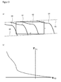
- FIG. 6 shows a naturally entangled flank line crown, as this can be generated by a mere correction of the grinding kinematics.
- the direction along which the generated modification is constant is given by the contact path 10. With the method described here, however, this direction can be chosen freely.
- the direction chosen so that the line with constant modification 12 parallel to the w axis.
- the modification produced along the contact path 11 has no constant value.
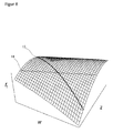
- the direction of constant modification can also be arbitrarily chosen so that one, as in FIG. 8 shown running in a targeted direction crowning can be generated.
- Such crowns produce a purposeful entanglement and, like unconstrained flank line crowns, are free from deviations in form.
- final returns can according to the prior art only in distorted form 16, as in FIG. 9 shown to be made by corrected grinding kinematics.
- the line of constant modification runs along the contact path 15. However, a course of this line is desired parallel to the w axis, as 18 in FIG. 10 shows what is possible with the method described here. This leads to an undistorted final withdrawal 19.
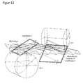
- a variation of the final redemptions are triangular end reductions 22, as in FIG. 11 shown.
- the line of constant modification 21 runs here in a deliberately predetermined direction, typically parallel to the engagement line of the toothing.
- the final reductions and triangular final reductions shown here have linear gradients without transition areas. However, circular, logarithmic, parabolic and exponential courses, with and without a transitional area or any other form of course, are also possible here.
Landscapes
- Engineering & Computer Science (AREA)
- Mechanical Engineering (AREA)
- Human Computer Interaction (AREA)
- Manufacturing & Machinery (AREA)
- Physics & Mathematics (AREA)
- General Physics & Mathematics (AREA)
- Automation & Control Theory (AREA)
- Grinding-Machine Dressing And Accessory Apparatuses (AREA)
- Gear Processing (AREA)
Abstract
Die vorliegende Erfindung zeigt ein Verfahren zur Verzahnbearbeitung eines Werkstückes durch ein Diagonalwälzverfahren, bei welchem das Werkstück durch das Abwälzen eines Werkzeuges verzahnbearbeitet wird, wobei während der Bearbeitung ein Axialvorschub des Werkzeuges mit einem durch das Verhältnis zwischen Axialvorschub des Werkzeuges und Axialvorschub des Werkstückes gegebenen Diagonalverhältnis erfolgt. Dabei wird im Rahmen der Bearbeitung eines Werkstückes das Diagonalverhältnis verändert.The present invention shows a method of tooth processing a workpiece by a diagonal rolling method, in which the workpiece is toothed by rolling a tool, wherein during machining axial feed of the tool with a given by the ratio between axial feed of the tool and axial feed of the workpiece diagonal ratio , The diagonal ratio is changed during the machining of a workpiece.
Description
Die vorliegende Erfindung betrifft ein Verfahren zur Verzahnbearbeitung eines Werkstückes durch ein Diagonalwälzverfahren. Bei einem solchen Diagonalwälzverfahren wird das Werkstück durch das Abwälzen eines Werkzeuges verzahnbearbeitet.The present invention relates to a method for tooth processing a workpiece by a diagonal rolling process. In such a Diagonalwälzverfahren the workpiece is toothed by the rolling of a tool.
Die Erfindung betrifft dabei ein Diagonalwälzverfahren, bei welchem während der Bearbeitung ein Axialvorschub des Werkzeuges mit einem durch das Verhältnis zwischen Axialvorschub des Werkzeuges und Axialvorschub des Werkstückes gegebenen Diagonalverhältnis erfolgt. Mit dem Begriff "Axialvorschub des Werkzeuges" ist dabei eine Relativbewegung des Werkzeuges zum Werkstück in Axialrichtung des Werkzeuges gemeint. Mit dem Begriff "Axialvorschub des Werkstückes" ist eine Relativbewegung des Werkzeuges zum Werkstück in Axialrichtung des Werkstückes gemeint. Je nach Ausgestaltung der Verzahnbearbeitungsmaschine, auf welcher das erfindungsgemäße Verfahren durchgeführt wird, können dabei unterschiedliche Maschinenachsen zur Erzeugung des Axialvorschubs des Werkzeuges und der Axialvorschubs des Werkstückes herangezogen werden. Beispielsweise kann dabei ausschließlich das Werkzeug sowohl in Richtung seiner Achse, als auch in Richtung der Achse des Werkstückes verfahren werden. Da es sich um ein Wälzverfahren handelt, sind weiterhin die Rotationsbewegungen des Werkzeuges und des Werkstückes gekoppelt. Bei dem Werkstück kann es sich insbesondere um ein Zahnrad handeln.The invention relates to a Diagonalwälzverfahren in which an axial feed of the tool during processing with a given by the ratio between axial feed of the tool and axial feed of the workpiece diagonal ratio. The term "axial feed of the tool" means a relative movement of the tool to the workpiece in the axial direction of the tool. By the term "axial feed of the workpiece" is meant a relative movement of the tool to the workpiece in the axial direction of the workpiece. Depending on the configuration of the gear cutting machine on which the method according to the invention is carried out, different machine axes can be used to generate the axial feed of the tool and the axial feed of the workpiece. For example, only the tool can be moved both in the direction of its axis, as well as in the direction of the axis of the workpiece. Since it is a rolling process, the rotational movements of the tool and the workpiece are further coupled. The workpiece may in particular be a gear.
Bei der Verzahnbearbeitung im Diagonalwälzverfahren kommen durch den Axialvorschub des Werkzeuges, welcher auch als Vershiften bezeichnet wird, nacheinander unterschiedliche Bereiche des Werkzeuges mit dem Werkstück in Kontakt. Solche Diagonalwälzverfahren werden üblicherweise dazu eingesetzt, um eine möglichst gleichmäßige Abnutzung der Werkzeugoberfläche zu erreichen.In the gear processing in the diagonal rolling process come through the axial feed of the tool, which is also referred to as Vershiften, successively different areas of the tool with the workpiece in contact. Such Diagonalwälzverfahren are usually used to achieve the most uniform wear of the tool surface.
Aus der
Aus der
Aufgabe der vorliegenden Erfindung ist es, die aus dem Stand der Technik bekannten Diagonalwälzverfahren weiterzuentwickeln und zu verbessern. Ein mögliches Ziel der vorliegenden Erfindung kann dabei sein, die Flexibilität des Bearbeitungsverfahrens zu verbessern, insbesondere im Hinblick auf die erzeugbaren Modifikationen. Ein anderes Ziel der vorliegenden Erfindung kann darin liegen, die zur Verfügung stehenden Schleifbereiche der Schleifwerkzeuge besser nutzen zu können.The object of the present invention is to develop and improve the known from the prior art Diagonalwälzverfahren. One possible aim of the present invention may be to improve the flexibility of the machining process, in particular with regard to the producible modifications. Another object of the present invention may be to make better use of the available grinding areas of the grinding tools.
Diese Aufgabe wird erfindungsgemäß durch die unabhängigen Ansprüche der vorliegenden Anmeldung gelöst. Vorteilhafte Ausgestaltungen der vorliegenden Erfindung sind Gegenstand der Unteransprüche.This object is achieved by the independent claims of the present application. Advantageous embodiments of the present invention are the subject of the dependent claims.
Die vorliegende Erfindung zeigt ein Verfahren zur Verzahnbearbeitung eines Werkstückes durch ein Diagonalwälzverfahren, mit welchem das Werkstück durch das Abwälzen eines Werkzeuges verzahnbearbeitet wird. Während der Bearbeitung erfolgt ein Axialvorschub des Werkzeuges mit einem durch das Verhältnis zwischen Axialvorschub des Werkzeuges und Axialvorschub des Werkstückes gegebenen Diagonalverhältnis. Erfindungsgemäß wird dabei im Rahmen der Bearbeitung eines Werkstückes das Diagonalverhältnis verändert. Bei dem erfindungsgemäßen Verfahren zur Verzahnbearbeitung kann es sich dabei insbesondere um ein Verfahren zur Hartfeinbearbeitung und / oder ein Schleifverfahren handeln. Bei dem Werkstück handelt es sich bevorzugt um ein Zahnrad. Weiterhin kommt erfindungsgemäß als Werkzeug bevorzugt eine Schleifschnecke zum Einsatz.The present invention shows a method of tooth processing a workpiece by a diagonal rolling process, with which the workpiece by the rolling of a Tool is dovetailed. During machining, an axial feed of the tool takes place with a diagonal ratio given by the ratio between the axial feed of the tool and the axial feed of the workpiece. According to the invention, the diagonal ratio is changed during the machining of a workpiece. In particular, the method according to the invention for gear cutting can be a method for hard fine machining and / or a grinding method. The workpiece is preferably a gear. Furthermore, a grinding worm is preferably used according to the invention as a tool.
Das erfindungsgemäße Verfahren kann dabei insbesondere zur Bearbeitung zylindrischer oder konischer Werkstücke bzw. Verzahnungen eingesetzt werden. Die Verzahnungen können dabei symmetrisch oder asymmetrisch ausgeführt sein.The method according to the invention can be used in particular for machining cylindrical or conical workpieces or toothings. The teeth can be symmetrical or asymmetrical.
Bei den aus dem Stand der Technik bekannten Diagonalwälzverfahren war es zwar bekannt, vor der Durchführung des Verfahrens ein spezifisches Diagonalverhältnis auszuwählen, mit welchem dann die Verzahnbearbeitung erfolgte. Während der Bearbeitung des Werkstückes selbst wurde jedoch mit einem konstanten Diagonalverhältnis gearbeitet. Der Erfinder der vorliegenden Erfindung hat nun erkannt, dass durch eine Veränderung des Diagonalverhältnisses im Rahmen der Bearbeitung eines Werkstückes vielfältige neue Möglichkeiten eröffnet werden.In the case of the diagonal rolling methods known from the prior art, it was admittedly known to select a specific diagonal ratio before the method was carried out, with which the toothing processing then took place. During the processing of the workpiece itself, however, worked with a constant diagonal ratio. The inventor of the present invention has now recognized that a variety of new possibilities are opened by a change in the diagonal ratio in the context of processing a workpiece.
Bevorzugt erfolgt die erfindungsgemäße Veränderung des Diagonalverhältnisses dabei im Rahmen eines Verfahrens zur Herstellung eines Werkstückes mit korrigierter Verzahnungsgeometrie und / oder modifizierter Oberflächenstruktur, bei welchem mittels einer gezielten Modifikation der Oberflächengeometrie des Werkzeuges und einer durch das Diagonalwälzverfahren erzeugten, vom Diagonalverhältnis abhängigen Abbildung der Oberfläche des Werkzeuges auf die Oberfläche des Werkstückes eine entsprechende Modifikation auf der Oberfläche des Werkstückes erzeugt wird. Insbesondere kann im Rahmen eines solchen Verfahrens das Diagonalverhältnis verändert werden, um zusätzliche Variationsmöglichkeiten bei der Erzeugung der Modifikationen zur Verfügung zu stellen.The alteration of the diagonal ratio according to the invention preferably takes place in the context of a method for producing a workpiece having a corrected tooth geometry and / or modified surface structure, by means of a specific modification of the surface geometry of the tool and of a diagonal relationship-dependent imaging of the surface of the tool on the surface of the workpiece a corresponding modification on the surface of the workpiece is generated. In particular, in the context of such a method, the diagonal ratio can be changed in order to provide additional possibilities of variation in the generation of the modifications.
Im Rahmen eines solchen Verfahrens zur Erzeugung einer modifizierten Oberflächengeometrie des Werkstückes kann die gezielte Modifikation der Oberflächengeometrie des Werkzeuges erzeugt werden, indem die Position des Abrichters zum Werkzeug beim Abrichten in Abhängigkeit von dem Werkzeugdrehwinkel und / oder der Werkzeugbreitenposition variiert wird. Hierdurch ergibt sich eine besonders einfache Möglichkeit, Modifikationen der Oberflächengeometrie des Werkzeuges zu erzeugen.As part of such a method for producing a modified surface geometry of the workpiece, the targeted modification of the surface geometry of the tool can be generated by the position of the dresser is varied to the tool during dressing in dependence on the tool rotation angle and / or the tool width position. This results in a particularly simple way to produce modifications of the surface geometry of the tool.
Das Abrichten kann dabei ein- oder zweiflankig erfolgen. Weiterhin kann das Abrichten in einem Hub erfolgen, oder in mehreren Hüben.The dressing can be done on one or two sides. Furthermore, the dressing can be done in one stroke, or in several strokes.
Insbesondere kann die Profilrolle dabei beim Abrichten vom Fußbereich bis zum Kopfbereich mit dem Zahn des Werkzeuges in Kontakt stehen, so dass die Modifikation über die gesamte Zahnhöhe in einem Hub erfolgt.In particular, the profile roller can be in contact with the tooth of the tool during dressing from the foot area to the head area, so that the modification takes place over the entire tooth height in one stroke.
Alternativ kann die Profilrolle beim Abrichten nur in Teilbereichen zwischen Fuß und Kopf mit dem Zahn des Werkzeuges in Kontakt stehen, so dass die Modifikation über die Zahnhöhe in mehreren Hüben erfolgt.Alternatively, the profile role in dressing only in partial areas between the foot and head are in contact with the tooth of the tool, so that the modification takes place over the tooth height in several strokes.
Das Abrichten des Zahnkopfes kann über einen Kopfabrichter erfolgen.The dressing of the tooth head can be done via a Kopfabrichter.
Die vorliegende Erfindung kann jedoch auch bei nicht-abrichtbaren Werkzeugen zum Einsatz kommen. In diesem Fall werden die Modifikationen des Werkzeugs nicht während des Abrichtens, sondern bereits bei der Herstellung der Werkzeuge erzeugt. Hierzu kann jedoch ggf. ein dem Abrichten entsprechendes Verfahren eingesetzt werden. Bevorzugt kommt die vorliegende Erfindung aber bei abrichtbaren Werkzeugen zum Einsatz.However, the present invention can also be used with non-dressable tools. In this case, the modifications of the tool are not generated during the dressing, but already during the production of the tools. However, if necessary, a method corresponding to the dressing can be used for this purpose. Preferably, however, the present invention is used in dressable tools.
Bevorzugt weist die Modifikation der Oberflächengeometrie des Werkstückes auf der Zahnflanke im Wälzbild zumindest in einem ersten Bereich und / oder lokal in einer ersten Richtung des Werkstückes einen konstanten Wert auf, während die Modifikation in einer zweiten Richtung des Werkstückes, welche senkrecht zur erstens Richtung verläuft, durch eine Funktion FFt2 gegeben ist.Preferably, the modification of the surface geometry of the workpiece on the tooth flank in the rolling image has a constant value at least in a first region and / or locally in a first direction of the workpiece, while the modification in a second direction of the workpiece, which is perpendicular to the first direction, is given by a function F Ft2 .
Weiterhin kann vorgesehen sein, dass die zur Herstellung der Modifikation der Oberflächengeometrie des Werkstückes verwendete Modifikation der Oberflächengeometrie des Werkzeuges im Wälzbild zumindest in einem ersten Bereich und / oder lokal in einer ersten Richtung des Werkzeuges einen konstanten Wert aufweist und weiterhin bevorzugt in einer zweiten Richtung des Werkzeuges, welche senkrecht zur ersten Richtung verläuft, durch eine Funktion FFt1 gegeben ist. Bevorzugt ist die Funktion FFt1 auf dem Werkzeug dabei die gleiche, gegebenenfalls linear um einen Faktor gestauchte Funktion wie die Funktion FFt2 auf dem Werkstück. Die lineare Stauchung kann dabei das Argument der Funktion betreffen, und/oder die Größe der Funktion. Selbstverständlich hat die Modifikation auf dem Werkstück dabei das umgekehrte Vorzeichen wie die Modifikation auf dem Werkzeug, da Erhebungen auf der Werkzeugoberfläche Vertiefungen auf der Werkstückoberfläche erzeugen und umgekehrt. Im Normalschnitt kann dabei insbesondere FFt1(x) = - FFt2(cx) gelten, d.h. es liegt lediglich in Bezug auf das Argument eine Stauchung vor, im Stirnschnitt kann dagegen ein zusätzlicher konstanter Faktor k im Hinblick auf die Größe der Funktion vorliegen, d.h. FFt1(x) = - k * FFt2(cx). Die Faktoren k und c können dabei je nach den konkreten Randbedingungen größer oder kleiner 1 sein.Furthermore, it can be provided that the modification of the surface geometry of the tool used in the rolling pattern for producing the modification of the surface geometry of the workpiece has a constant value at least in a first region and / or locally in a first direction of the tool and furthermore preferably in a second direction of the tool Tool, which is perpendicular to the first direction, given by a function F Ft1 . Preferably, the function F Ft1 on the tool is the same, optionally linear compressed by a factor function as the function F Ft2 on the workpiece. The linear compression can relate to the argument of the function, and / or the size of the function. Of course, the modification on the workpiece has the opposite sign as the modification on the tool, since surveys on the tool surface produce depressions on the workpiece surface and vice versa. In the normal section, F Ft1 (x) = - F Ft2 (cx) can apply in particular, ie there is a compression only in relation to the argument, whereas in the endcut an additional constant factor k can be present with regard to the size of the function. ie F Ft1 (x) = - k * F Ft2 (cx). The factors k and c can be greater or less than 1, depending on the specific boundary conditions.
Erfindungsgemäß kann dabei die Makrogeometrie des Werkzeuges und / oder die Eingriffslinie des Abrichtwerkzeuges und / oder das Diagonalverhältnis und / oder der Stauchungsfaktor so gewählt werden, dass die Modifikation des Werkzeuges entlang einer ersten Linie, auf welcher sich der Berührpunkt bei der Bearbeitung des Werkstückes auf dem Werkzeug bewegt, der gewünschten Modifikation des Werkstückes entlang einer zweiten Linie, auf welcher sich der Berührpunkt auf dem Werkstück bewegt, entspricht. Insbesondere werden die Parameter dabei so gewählt, dass durch die auf dem Werkzeug erzeugte Modifikation die auf dem Werkstück gewünschte Modifikation erzeugt wird.According to the invention, the macrogeometry of the tool and / or the engagement line of the dressing tool and / or the diagonal ratio and / or the compression factor can be selected such that the modification of the tool along a first line on which the contact point in the machining of the workpiece on the Tool moves, the desired modification of the workpiece along a second line on which the contact point moves on the workpiece corresponds. In particular, the parameters are chosen such that the modification desired on the workpiece is generated by the modification produced on the tool.
Die Veränderung des Diagonalverhältnisses gemäß der vorliegenden Erfindung kann jedoch nicht nur bei solchen Verfahren zur Herstellung eines Werkstückes mit korrigierter Verzahnungsgeometrie eingesetzt werden, sondern auch bei einem Diagonalwälzverfahren, bei welchem unmodifizierte Werkzeuge zum Einsatz kommen und/oder bei welchen die Werkstücke nicht modifiziert werden.However, the variation of the diagonal ratio according to the present invention can be applied not only to such methods of manufacturing a workpiece having a corrected gear geometry, but also to a diagonal rolling method using unmodified tools and / or to which the workpieces are not modified.
Gemäß der vorliegenden Erfindung werden bevorzugt evolventische Verzahnungen erzeugt. Die erfindungsgemäß angegebenen Modifikationen beziehen sich dabei auf eine Modifikation gegenüber einer durch eine Evolventenverzahnung gegebenen Oberflächengeometrie. Vorteilhafterweise werden dabei evolventische Werkzeuge, welche ggf. entsprechend modifiziert sind, eingesetzt.According to the present invention, involute gears are preferably produced. The modifications specified according to the invention relate to a modification with respect to a given by an involute toothing surface geometry. Advantageously, involute tools, which are possibly modified accordingly, are used.
Gemäß einer ersten Variante der vorliegenden Erfindung kann zur Bearbeitung unterschiedlicher Bereiche des Werkstückes mit unterschiedlichen Diagonalverhältnissen gearbeitet werden. Insbesondere kann bei einem solchen Verfahren das Diagonalverhältnis geändert werden, während das Werkstück mit dem Werkzeug in Kontakt steht und durch das Werkzeug verzahnbearbeitet wird, d.h. während eines laufenden Bearbeitungsschrittes. Alternativ oder zustätzlich unterscheiden sich dabei während der Durchfürhung eines Bearbeitungsschrittes die zum Vorschub des Werkzeuges eingesetzten Diagonalverhältnisse an mindestens zwei Punkten des während der Bearbeitung zurückgelegten Axialvorschubs des Werkzeuges und / oder Werkstückes. Insbesondere kann dabei das Diagonalverhältnis verändert werden, während im Rahmen eines Bearbeitungsschrittes die Breite der Verzahnung abgefahren wird.According to a first variant of the present invention can be used for processing different areas of the workpiece with different diagonal ratios. In particular, in such a method, the diagonal ratio can be changed while the workpiece is in contact with the tool and is tooth-processed by the tool, ie during an ongoing machining step. Alternatively or additionally, during the execution of a machining step, the diagonal ratios used for advancing the tool differ at at least two points of the axial feed of the tool and / or workpiece during machining. In particular, the diagonal ratio can be used be changed while the width of the toothing is traversed in a processing step.
In einer zweiten Variante, welche in einer möglichen Ausführungsform mit der ersten Variante kombiniert wird, kann bei der Verwendung unterschiedlicher Bereiche des Werkzeuges mit unterschiedlichen Diagonalverhältnissen gearbeitet werden.In a second variant, which is combined in a possible embodiment with the first variant, it is possible to work with different diagonal ratios when using different regions of the tool.
Zum einen kann bei Verwendung unterschiedlicher Bereiche des Werkzeuges, welche jedoch zu einem zusammenhängenden, während eines Bearbeitungsschrittes zum Bearbeiten des Werkstückes eingesetzten Bearbeitungsbereich gehören, mit unterschiedlichen Diagonalverhältnissen gearbeitet wird. Ein solches Vorgehen ergibt sich aufgrund des erfindungsgemäßen Diagonalschleifverfahrens, bei welchen während eines Bearbeitungsschrittes unterschiedliche Bereiche des Werkstückes mit unterschiedlichen Bereichen des Werkzeuges bearbeitet werden, automatisch, wenn gemäß der ersten Variante zur Bearbeitung unterschiedlicher Bereiche des Werkstückes mit unterschiedlichen Diagonalverhältnissen gearbeitet wird.On the one hand, when using different areas of the tool, which, however, belong to a contiguous, used during a machining step for machining the workpiece processing area, is operated with different diagonal ratios. Such a procedure is due to the diagonal grinding method according to the invention, in which different areas of the workpiece are machined with different areas of the tool during a processing step, automatically when working according to the first variant for processing different areas of the workpiece with different diagonal ratios.
Jedoch können auch dann, wenn das Werkzeug zwei separate, für unterschiedliche Bearbeitungsschritte eingesetzte Bereiche aufweist, in diesen unterschiedlichen Bereichen mit unterschiedlichen Diagonalverhältnissen gearbeitet werden. In diesem Fall können die beiden unterschiedlichen Bereiche des Werkzeuges dazu eingesetzt werden, um den gleichen Bereich des Werkstückes zu bearbeiten.However, even if the tool has two separate areas used for different processing steps, different diagonal ratios can be used in these different areas. In this case, the two different areas of the tool can be used to machine the same area of the workpiece.
Bei beiden Varianten der vorliegenden Erfindung kann in einer möglichen Ausführungsform der vorliegenden Erfindung innerhalb der jeweiligen Bereiche mit einem konstanten Diagonalverhältnis gearbeitet werden. Insbesondere können dabei zwei oder mehr Bereiche vorgesehen sein, innerhalb welcher jeweils mit einem konstanten Diagonalverhältnis gearbeitet wird, wobei sich die Diagonalverhältnisse mindestens zweier Bereiche unterscheiden.In both variants of the present invention, in one possible embodiment of the present invention, a constant diagonal ratio can be worked within the respective regions. In particular, two or more regions can be provided, within each of which a constant diagonal ratio is used, the diagonal ratios of at least two regions being different.
Alternativ hierzu kann das Diagonalverhältnis während der Bearbeitung des Werkstückes in Abhängigkeit von dem Axialvorschub des Werkzeuges variiert werdenDabei kann das Diagonalverhältnis zumindest in einem Bereich des Axialvorschubs als eine nicht konstante und ggf. stetige Funktion des Axialvorschubs gegeben sein. Insbesondere kann das Diagonalverhältnis dabei in Abhängigkeit von dem Axialvorschub frei vorgegeben werden. Wie bereits oben dargestellt, kann die erfindungsgemäße Veränderung des Diagonalverhältnisses dazu eingesetzt werden, um die sich erfindungsgemäß bei dem oben beschriebenen Verfahren zur Erzeugung von modifizierten Oberflächen eines Werkstückes ergebenden Modifikationen zu beeinflussen. Insbesondere kann dabei die Veränderung des Diagonalverhältnisses dazu eingesetzt werden, um die Ausrichtung der sich auf dem Werkstück ergebenden Modifikationen zu verändern.Alternatively, the diagonal ratio can be varied during machining of the workpiece as a function of the axial feed of the tool. At least in a range of the axial feed, the diagonal ratio can be given as a non-constant and possibly continuous function of the axial feed. In particular, the diagonal ratio can be freely specified as a function of the axial feed. As already stated above, the change of the diagonal ratio according to the invention can be used to influence the modifications resulting according to the invention in the above-described method for producing modified surfaces of a workpiece. In particular, the change of the diagonal ratio can be used to change the orientation of the resulting on the workpiece modifications.
Dabei wird im Diagonalwälzverfahren die modifizierte Oberfläche des Werkzeuges auf die Oberfläche des Werkstückes abgebildet, wobei diese Abbildung vom gewählten Diagonalverhältnis abhängt. Insbesondere hängt dabei die erste Richtung des Werkstückes, auf welche die erste Richtung des Werkzeuges, in welcher die Modifikation konstant ist, abgebildet wird, von dem gewählten Diagonalverhältnis ab. Durch die Veränderung des Diagonalverhältnisses während der Bearbeitung unterschiedlicher Bereiche des Werkstückes kann damit in diesen unterschiedlichen Bereichen des Werkstückes eine unterschiedliche Ausrichtung der Modifikation erreicht werden.In this case, the modified surface of the tool is imaged on the surface of the workpiece in the diagonal rolling process, this figure depending on the selected diagonal ratio. In particular, the first direction of the workpiece, to which the first direction of the tool in which the modification is constant, depends on the selected diagonal ratio. By changing the diagonal ratio during the processing of different areas of the workpiece, a different orientation of the modification can thus be achieved in these different areas of the workpiece.
Wird dabei in zwei oder mehr Bereichen jeweils mit einem konstanten, jedoch unterschiedlichen Diagonalverhältnis gearbeitet, ergeben sich dementsprechend unterschiedliche, jedoch innerhalb der Bereiche konstante Ausrichtungen der Modifikationen. Wird dagegen das Diagonalverhältnis innerhalb eines Bereiches variiert, ergibt sich eine entsprechende Variation in der Ausrichtung. Ist das Diagonalverhältnis dabei durch eine stetige, nicht konstante Funktion gegeben, ergibt sich dementsprechend eine stetige Veränderung in der Ausrichtung der Modifikation.If in each case a constant, but different diagonal ratio is used in two or more regions, correspondingly different, but within the ranges constant alignments of the modifications result. If, on the other hand, the diagonal ratio varies within a range, there is a corresponding variation in the orientation. If the diagonal ratio is given by a continuous, non-constant function, the result is a constant change in the orientation of the modification.
In einer möglichen Ausführungsform der vorliegenden Erfindung kann der Verlauf mindestens einer Linie konstanter Modifikation vorgeben werden und hieraus die Variation des Diagonalverhältnisses in Abhängigkeit des Axialvorschubs und insbesondere die nicht-konstante Funktion, durch welche dieser gegeben ist, bestimmt werden. Insbesondere führt dabei eine Linien konstanter Modifikation, welche im Wälzdiagramm keine Gerade bildet, zu einer nicht-konstanten Funktion. Bevorzugt kann dabei der Verlauf zumindest einer Linie konstanter Modifikation zumindest innerhalb gewisser Randbedingungen frei vorgegeben werden.In one possible embodiment of the present invention, the course of at least one line of constant modification can be specified and from this the variation of the diagonal ratio as a function of the axial feed and in particular the non-constant function by which it is given can be determined. In particular, a line of constant modification, which forms no straight line in the rolling diagram, leads to a non-constant function. Preferably, the course of at least one line of constant modification can be freely specified, at least within certain boundary conditions.
Dabei kann die Funktion, welche das Diagonalverhältnisses in Abhängigkeit des Axialvorschubs beschreibt, zumindest einen Bereich aufweisen, in dem sie einen stetigen nicht-konstanten Verlauf aufweist. Dies würde einer stetigen Krümmung der Linie konstanter Modifikation entsprechen.In this case, the function which describes the diagonal ratio as a function of the axial advance may have at least one region in which it has a continuous non-constant course. This would correspond to a continuous curvature of the line of constant modification.
Bevorzugt erfolgt die Variation des Diagonalverhältnisses dabei beim Überstreichen eines modifizierten Bereichs des Werkstücks, so dass sich in diesem Bereich die Ausrichtung der Modifikation ändert.In this case, the variation of the diagonal ratio preferably takes place when passing over a modified area of the workpiece, so that the orientation of the modification changes in this area.
Die erfindungsgemäße Variation des Diagonalverhältnisses kann dabei sowohl beim Einsatz eines zylindrischen, als auch beim Einsatz eines konischen Werkzeuges eingesetzt werden. Dabei kann die Modifikation des Werkstücks in beiden Fällen durch die Variation des Diagonalverhältnisses beeinflusst werden.The variation of the diagonal ratio according to the invention can be used both when using a cylindrical and when using a conical tool. In this case, the modification of the workpiece in both cases can be influenced by the variation of the diagonal ratio.
Bevorzugt kann für die Durchführung eines erfindungsgemäßen Verfahrens, bei welchem eine Veränderung des Diagonalverhältnisses erfolgt, während das Werkzeug am Werkstück in Breitenrichtung entlanggeführt wird, ein konisches Werkzeug eingesetzt werden, d.h. ein Werkzeug mit einer konischen Grundform. Hierdurch können die sich durch die Variation des Diagonalverhältnisses ergebenden Modifikationen zusätzlich durch die Einstellung bestimmter Parameter des Werkzeuges oder des Bearbeitungsverfahrens gezielt beeinflusst werden. Bevorzugt wird dabei ein konisches Werkzeug eingesetzt, wenn das Diagonalverhältnis als eine stetige, nicht konstante Funktion gegeben ist.Preferably, for carrying out a method according to the invention in which a change in the diagonal ratio takes place while the tool is being guided along the workpiece in the width direction, a conical tool can be used, i. a tool with a conical basic shape. As a result, the modifications resulting from the variation of the diagonal ratio can additionally be influenced in a targeted manner by setting certain parameters of the tool or of the machining method. Preferably, a conical tool is used when the diagonal ratio is given as a continuous, non-constant function.
Das erfindungsgemäße Werkzeug mit einer konischen Grundform weist dabei bevorzugt eine Evolventenverzahnung auf, welche jedoch gegebenenfalls Modifikationen aufweisen kann. Evolventische Verzahnungen weisen dabei eine Geometrie auf, welche sich durch den Hüllschnitt zwischen einem Zylinder und einer Zahnstange ergibt. Die konische Grundform ergibt sich dabei dadurch, dass im Rahmen dieses Hüllschnittes die Drehachse des Zylinders gegen die Hauptebene der Zahnstange verkippt ist.The tool according to the invention with a conical basic shape preferably has an involute toothing, which may, however, have modifications. Evolventic gears have a geometry that results from the Hüllschnitt between a cylinder and a rack. The basic conical shape results from the fact that in the context of this Hüllschnittes the axis of rotation of the cylinder is tilted against the main plane of the rack.
Gemäß einer bevorzugten Ausführungsform ist der Konuswinkel des Werkzeuges größer als 1', weiterhin bevorzugt größer als 30', und weiter bevorzugt größer als 1°. Bevorzugt ist der Konuswinkel des Werkzeuges jedoch kleiner als 50°, weiter bevorzugt kleiner als 20°, und weiterhin bevorzugt kleiner als 10°.According to a preferred embodiment, the cone angle of the tool is greater than 1 ', more preferably greater than 30', and more preferably greater than 1 °. However, the cone angle of the tool is preferably less than 50 °, more preferably less than 20 °, and further preferably less than 10 °.
Insbesondere können die durch die Veränderung des Diagonalverhältnisses erzielbaren Modifikationen dabei beim Einsatz eines konischen Werkzeuges durch eine geeignete Wahl mindestens eines und bevorzugt mehrerer Parameters des Bearbeitungsvorgangs und/oder der Makrogeometrie des Werkzeuges, insbesondere des Achskreuzwinkels und/oder des Achsabstands und/oder des Konuswinkels und/oder des Profilwinkels des Werkzeuges gezielt beeinflusst werden.In particular, the modifications achievable by the change in the diagonal ratio can be achieved by a suitable choice of at least one and preferably several parameters of the machining process and / or the macrogeometry of the tool, in particular the Achskreuzwinkels and / or the center distance and / or the cone angle and / or the profile angle of the tool can be influenced.
Zum einen kann hierdurch eine gewünschte Ausrichtung der Modifikation auf der linken und rechten Zahnflanke erreicht werden. Insbesondere umfasst das vorliegende Verfahren dabei einen Schritt der Vorgabe einer gewünschten Ausrichtung der Modifikation auf der linken und rechten Zahnflanke, und der Bestimmung eines hierfür geeigneten Parameters und/oder einer hierfür geeigneten Kombination an Parametern des Bearbeitungsvorgangs und/oder der Makrogeometrie des Werkzeuges.On the one hand, this makes it possible to achieve a desired alignment of the modification on the left and right tooth flanks. In particular, the present method comprises a step of specifying a desired orientation of the modification on the left and right tooth flanks, and determining a parameter suitable for this and / or a suitable combination of parameters of the machining process and / or the macrogeometry of the tool.
Weiterhin kann durch die geeignete Wahl mindestens eines und bevorzugt mehrerer Parameters des Bearbeitungsvorgangs und/oder der Makrogeometrie des Werkzeuges auch die Modifikation auf einer Zahnflanke als solche beeinflusst werden. Insbesondere kann dabei die Ausrichtung und/oder Steigung der Modifikation in unterschiedlichen Bereichen der Zahnflanke beeinflusst werden.Furthermore, by the suitable choice of at least one and preferably several parameters of the machining process and / or the macrogeometry of the tool, the modification on a tooth flank as such can also be influenced. In particular, the orientation and / or slope of the modification in different regions of the tooth flank can be influenced.
Die gleichen Möglichkeiten ergeben sich auch, wenn das Werkstück eine konische Verzahnung aufweist, und zwar sowohl beim Einsatz eines konischen, als auch eines zylindrischen Werkzeugs.The same possibilities arise when the workpiece has a conical toothing, both when using a conical, as well as a cylindrical tool.
Das erfindungsgemäße Werkzeug kann dabei in einer ersten Variante mindestens einen modifizierten und einen unmodifizierten Bereich aufweisen. Bevorzugt weist das Werkzeug dabei zwei modifizierte Bereiche auf, zwischen welchen ein unmodifizierter Bereich liegt. Sind dabei zwei modifizierte Bereiche vorgesehen, können die Ausrichtung der Modifikationen und insbesondere die erste Richtung der Modifikationen in diesen Bereichen identisch sein. Hierdurch ergibt sich ein besonders einfaches Abrichtverfahren. Bevorzugt wird dann in den beiden modifizierten Bereichen mit unterschiedlichen Diagonalverhältnissen gearbeitet, um hierdurch eine unterschiedliche Ausrichtung der Modifikation auf dem Werkstück zu erreichen.The tool according to the invention can have at least one modified and one unmodified area in a first variant. In this case, the tool preferably has two modified regions, between which lies an unmodified region. If two modified regions are provided, the orientation of the modifications and in particular the first direction of the modifications in these regions can be identical. This results in a particularly simple dressing method. Preferably, work is then carried out in the two modified regions with different diagonal ratios in order to achieve a different orientation of the modification on the workpiece.
In einer zweiten Variante kann das Werkzeug zwei Bereiche mit unterschiedlichen Modifikationen aufweisen. Insbesondere können die Modifikationen dabei eine unterschiedliche Ausrichtung, insbesondere eine unterschiedliche erste Richtung, aufweisen. Hierdurch ergeben sich noch größere Freiheitsgrade bei der Erzeugung unterschiedlich ausgerichteter Modifikationen auf dem Werkstück.In a second variant, the tool can have two areas with different modifications. In particular, the modifications may have a different orientation, in particular a different first direction. This results in even greater degrees of freedom in the production of differently oriented modifications on the workpiece.
Weiterhin kann die zweite Variante auch mit der ersten Variante kombiniert werden, indem zusätzlich zu den zwei Bereichen mit unterschiedlichen Modifikationen ein unmodifizierter Bereich vorgesehen ist, welcher insbesondere zwischen den beiden modifizierten Bereichen angeordnet sein kann.Furthermore, the second variant can also be combined with the first variant in that, in addition to the two regions with different modifications, an unmodified region is provided, which can be arranged in particular between the two modified regions.
Sind mehrere modifizierte Bereiche vorgesehen, können sich die Modifikationen in den beiden Bereichen im Hinblick auf die Form FFt der Modifikation in der zweiten Richtung unterscheiden.If several modified regions are provided, the modifications in the two regions may differ with respect to the shape F Ft of the modification in the second direction.
Erfindungsgemäß modifizierte Werkzeuge können dabei insbesondere dazu eingesetzt werden, um auf unterschiedlichen Bereichen des Werkstückes unterschiedliche Modifikationen vorzunehmen, beispielsweise an der Ober- und Unterkante unterschiedliche und insbesondere unterschiedlich ausgerichtete Rücknahmen zu erzeugen.According to the invention modified tools can be used in particular to make different modifications to different areas of the workpiece, for example, to produce at the top and bottom edges of different and especially differently oriented redemptions.
In einer alternativen Ausgestaltung der vorliegenden Erfindung kann das Werkzeug mindestens zwei Bereiche aufweisen, welche nacheinander zur Bearbeitung des gleichen Bereiches des Werkstückes eingesetzt werden. Insbesondere kann es sich bei den beiden Bereichen dabei um einen Schruppbereich und einen Schlichtbereich handeln. Der Schruppbereich wird dabei eingesetzt, um einen größeren Materialabtrag bei geringerer Genauigkeit zu erreichen. Der Schlichtbereich wird dagegen nach der Schruppbearbeitung eingesetzt, um die Qualität der Oberflächengeometrie zu verbessern.In an alternative embodiment of the present invention, the tool may have at least two areas, which are used successively for machining the same area of the workpiece. In particular, the two areas can be a roughing area and a sizing area. The roughing area is used to achieve a larger material removal with lower accuracy. The sizing area, on the other hand, is used after roughing to improve the quality of the surface geometry.
Vorteilhafterweise werden dabei die Bearbeitungsschritte mit den beiden Bereichen mit unterschiedlichen Diagonalverhältnissen durchgeführt. Insbesondere kann dabei beim Schruppschritt mit einem anderen Diagonalverhältnis gearbeitet werden als beim Schlichtschritt. Die Diagonalverhältnisse während der jeweiligen Bearbeitungsschritte können dagegen konstant gehalten werden.Advantageously, the processing steps are carried out with the two areas with different diagonal ratios. In particular, it is possible to work with a different diagonal ratio during the roughing step than during the finishing step. The diagonal ratios during the respective processing steps, however, can be kept constant.
Der Einsatz unterschiedlicher Diagonalverhältnisse in den beiden Werkzeugbereichen erlaubt es, die gegebene Werkzeugbreite besser zu nutzen. Insbesondere kann dabei einer der beiden Bereiche kürzer sein als der andere Bereich, obwohl diese zur Bearbeitung des gleichen Werkstückes eingesetzt werden. Entsprechend muss nur das Diagonalverhältnis an die jeweilige Breite des Bearbeitungsbereiches des Werkzeuges angepasst werden.The use of different diagonal ratios in the two tool areas makes it possible to make better use of the given tool width. In particular, while one of the two areas may be shorter than the other area, although they are used for processing the same workpiece. Accordingly, only the diagonal ratio must be adapted to the respective width of the machining area of the tool.
Bevorzugt nutzen dabei die zur Bearbeitung des Werkstücks eingesetzten Bereiche die gesamte Werkzeugbreite.The areas used for machining the workpiece preferably utilize the entire tool width.
Ein solches Vorgehen ist unabhängig davon, ob mit einem modifizierten Werkzeug gearbeitet wird oder nicht, von Vorteil.Such a procedure is advantageous regardless of whether working with a modified tool or not.
In einer bevorzugten Ausführungsform der vorliegenden Erfindung ist jedoch insbesondere der Schlichtbereich modifiziert. Je nach Größe der Modifikation muss der Schruppbereich dagegen nicht unbedingt modifiziert sein. Er kann jedoch ebenfalls modifiziert sein.However, in a preferred embodiment of the present invention, in particular, the sizing region is modified. However, depending on the size of the modification, the roughing area does not necessarily have to be modified. However, it can also be modified.
Sind dabei beide Bereiche, und insbesondere sowohl der Schrupp- als auch der Schlichtbereich, modifiziert, so weisen die Modifikationen in einer möglichen Ausführungsform jeweils eine unterschiedliche Ausrichtung auf. Dabei ist die Modifikation, welche durch die beiden Bereiche auf dem Werkstück erzeugt werden soll, natürlich jeweils die gleiche. Durch die jeweils unterschiedlichen Diagonalverhältnisse würden identische Modifikationen in den beiden Bereichen jedoch unterschiedlich auf das Werkstück abgebildet. Bevorzugt sind die Modifikationen in den beiden Bereichen daher unterschiedlich ausgerichtet, sodass sie unter Berücksichtigung des unterschiedlichen Diagonalverhältnisses jeweils auf die gleiche Richtung auf dem Werkstück abgebildet werden. Insbesondere kann hierbei ein nicht-abrichtbares Werkzeug eingesetzt werden, da bei der Herstellung der Modifikationen auf einem solchen Werkzeug größere Freiheiten bestehen. Bei abrichtbaren Werkzeuges kann dagegen ggf. durch die Berührlinie des Abrichters eine Einschränkung bestehen.If both regions, and in particular both the roughing and the sizing region, are modified, the modifications in one possible embodiment each have a different orientation. Of course, the modification that is to be generated by the two areas on the workpiece, respectively, is the same in each case. Due to the different diagonal ratios, however, identical modifications in the two areas would be mapped differently on the workpiece. Preferably, the modifications in the two areas are therefore oriented differently, so that they are mapped to the same direction on the workpiece, taking into account the different diagonal ratio. In particular, in this case a non-dressable tool can be used, since in the production of the modifications on such a tool greater freedom exist. In the case of dressable tools, on the other hand, there may be a restriction due to the contact line of the dresser.
In einer alternativen Ausführungsform beide Bereiche, und insbesondere sowohl der Schrupp- als auch der Schlichtbereich, modifiziert sein und eine identische Ausrichtung der Modifikationen aufweisen. Solche Werkzeuge sind leichter durch den oben beschriebenen Abrichtprozess herstellbar, da die Eingriffslinie des Abrichters in das Werkzeug und damit die Richtung der Modifikation auf dem Werkzeug kaum veränderbar sind. Durch die unterschiedlichen Diagonalverhältnisse in den beiden Bereichen führt dies zwar zu unterschiedlichen Ausrichtung der Modifikation auf dem Werkstück. Da der Schruppbereich jedoch ohnehin nur für eine Grobbearbeitung eingesetzt wird, und die endgültige Oberflächenform erst durch den Schlichtschritt erzeugt wird, kann dies in manchen Fällen hingenommen werden.In an alternative embodiment, both regions, and in particular both the roughing and the sizing region, be modified and have an identical orientation of the modifications. Such tools are easier to produce by the dressing process described above, since the engagement line of the dresser in the tool and thus the direction of the modification on the tool are hardly changed. Although this results in different orientation of the modification on the workpiece due to the different diagonal ratios in the two areas. However, since the roughing area is used only for roughing anyway, and the final surface shape is produced only by the sizing step, in some cases this can be tolerated.
In diesem Fall führt die Modifikation des Schruppbereichs nur näherungsweise zu der gewünschten Modifikation auf der Verzahnung, wobei die tatsächliche Modifikation jedoch im erlaubten Toleranzbereich liegt. Bevorzugt wird das Diagonalverhältnis für den Schlichtschritt dabei so gewählt, dass sich die gewünschte Ausrichtung des Diagonalverhältnisses ergibt. Bevorzugt wird das Diagonalverhältnis für den Schruppschritt dagegen so gewählt, dass die tatsächliche Modifikation im erlaubten Toleranzbereich liegt. Ggf. kann dabei auch die Form der Modifikation, insbesondere die Funktion FFt1 im Schruppbereich gegenüber dem Schlichtbereich geändert werden.In this case, the modification of the roughing area only approximately leads to the desired modification on the toothing, but the actual modification is within the permitted tolerance range. Preferably, the diagonal ratio for the sizing step is selected such that the desired alignment of the diagonal ratio results. On the other hand, the diagonal ratio for the roughing step is preferably chosen such that the actual modification is within the permitted tolerance range. Possibly. It is also possible to change the form of the modification, in particular the function F Ft1, in the roughing area with respect to the finishing area.
Auch allgemein kann gemäß der vorliegenden Erfindung die Modifikation in mindestens einem Bereich des Werkzeuges, insbesondere im Schruppbereich, bei dem eingesetzten Diagonalverhältnis nur näherungsweise zu der gewünschten Modifikation auf der Verzahnung führen. Vorteilhafterweise werden die Form der Modifikation und das Diagonalverhältnis dabei so gewählt, dass die tatsächliche Modifikation im erlaubten Toleranzbereich liegt.Also generally, according to the present invention, the modification in at least one area of the tool, in particular in the roughing area, in the diagonal ratio used only approximately lead to the desired modification on the toothing. Advantageously, the shape of the modification and the diagonal ratio are chosen so that the actual modification is within the permitted tolerance range.
In einer weiteren Ausführungsform der vorliegenden Erfindung kann das Werkzeug mindestens zwei Bereiche aufweisen, welche nacheinander zur Bearbeitung unterschiedlicher Bereiche des Werkstückes eingesetzt werden. Erfindungsgemäß kann dabei die Bearbeitung in dem einen Bereich mit einem anderen Diagonalverhältnis erfolgen als in dem anderen Bereich.In a further embodiment of the present invention, the tool can have at least two regions, which are used successively for processing different regions of the workpiece. According to the invention, the machining can take place in the one area with a different diagonal ratio than in the other area.
Ein solches Vorgehen ist auch bei unmodifizierten Werkzeugen beispielsweise dann von Vorteil, wenn ein bestimmter Bereich des Werkzeuges während der Bearbeitung stärker beansprucht wird als ein anderer Bereich. Bevorzugt wird dabei mit einem größeren Diagonalverhältnis und damit einem schnelleren Axialvorschub des Werkzeuges gearbeitet, wenn das Werkzeug stärker beansprucht wird, und mit einem kleineren Diagonalverhältnis in Bereichen, in welchen das Werkzeug weniger stark belastet wird. Die größere Belastung kann sich insbesondere dadurch ergeben, dass mehr Material abzutragen ist als in anderen Bereichen. Durch ein solches Vorgehen ergibt sich ein gleichmäßigerer Verschleiß des Werkzeuges über die Werkzeugbreite, sodass seltener abgerichtet werden muss. Alternativ oder zusätzlich kann in Bereichen, in welchen geringere Toleranzen im Hinblick auf die Geometrie der Werkstückoberfläche zulässig sind, mit einem größeren Diagonalverhältnis gearbeitet werden, sodass das Werkzeug in diesem Bereich weniger stark verschleißt.Such an approach is also advantageous for unmodified tools, for example, when a certain area of the tool is subjected to greater stress during machining than another area. Preference is given to working with a larger diagonal ratio and thus a faster axial feed of the tool when the tool is more stressed, and with a smaller diagonal ratio in areas in which the tool is less heavily loaded. The greater burden can result in particular that more material is removed than in other areas. Such a procedure results in a more uniform wear of the tool over the tool width, so that less training is required. Alternatively or additionally, in areas in which lower tolerances with regard to the geometry of the workpiece surface are permitted, a larger diagonal ratio can be used so that the tool wears less in this area.
In einer weiteren Variante kann das Werkzeug jedoch auch einen modifizierten und einen unmodifizierten Bereich aufweisen, in welchen mit unterschiedlichen Diagonalverhältnissen gearbeitet wird.In a further variant, however, the tool can also have a modified and an unmodified region in which different diagonal ratios are used.
Dabei kann das Diagonalverhältnis in dem unmodifizierten Bereich kleiner gewählt werden als in dem modifizierten Bereich, um die Breite des Werkzeuges zu verringern, da so der unmodifizierte Bereich zur Bearbeitung eines größeren Bereiches des Werkstückes einsetzbar ist und kürzer sein kann als bei einem konstanten Diagonalverhältnis. Das größere Diagonalverhältnis im modifizierten Bereich kann dagegen durch die gewünschte Ausrichtung der Modifikation auf der Zahnflanke oder die gewünschte Auflösung in die zweite Richtung bestimmt sein. In einer anderen Variante kann das Diagonalverhältnis im unmodifizierten Bereich größer sein als in dem modifizierten Bereich, um in diesem Bereich die Belastung des Werkzeuges zu verringern. Ein solches Vorgehen macht insbesondere dann Sinn, wenn der unmodifizierte Bereich mehr Material abtragen muss als der modifizierte Bereich.In this case, the diagonal ratio in the unmodified region can be made smaller than in the modified region in order to reduce the width of the tool, since the unmodified region can be used for machining a larger region of the workpiece and can be shorter than at a constant diagonal ratio. The larger diagonal ratio in the modified range, on the other hand, may be due to the desired orientation of the modification on the tooth flank or the desired resolution in the be determined in the second direction. In another variant, the diagonal ratio in the unmodified region may be greater than in the modified region in order to reduce the load on the tool in this region. Such a procedure makes sense, in particular, when the unmodified area has to remove more material than the modified area.
Erfindungsgemäß kann dabei beispielsweise in einem Bereich, welcher zur Bearbeitung eines oberen oder unteren Endbereiches des Werkstückes eingesetzt wird, mit einem kleineren Diagonalverhältnis gearbeitet werden als in einem zur Bearbeitung eines mittleren Bereiches des Werkstückes eingesetzten Bereich. Denn bei der Bearbeitung des oberen oder unteren Endbereiches des Werkstückes taucht noch nicht das gesamte Werkzeug in das Werkstück ein, sodass die Belastungen hier niedriger sind.According to the invention, for example, in a region which is used for machining an upper or lower end region of the workpiece, a smaller diagonal ratio can be used than in a region used for machining a middle region of the workpiece. Because when processing the upper or lower end of the workpiece not yet dive the entire tool in the workpiece, so that the burden is lower here.
In einer weiteren Variante der vorliegenden Erfindung kann das Werkzeug zwei modifizierte Bereiche aufweisen, zwischen welchen ein unmodifizierter Bereich liegt, wobei die Bereiche nacheinander zur Bearbeitung unterschiedlicher Bereiche des Werkstückes eingesetzt werden. Bevorzugt wird dabei zumindest in den beiden modifizierten Bereichen mit unterschiedlichen Diagonalverhältnissen gearbeitet. Insbesondere können hierdurch in den jeweiligen Bereichen des Werkstückes unterschiedliche Modifikationen erzeugt werden, und insbesondre Modifikationen mit unterschiedlicher Ausrichtung und insbesondere mit unterschiedlicher erster Richtung. Die beiden modifizierten Bereiche des Werkzeuges können dabei die gleiche Ausrichtung der Modifikation aufweisen. Alternativ können jedoch auch hier bereits unterschiedliche Ausrichtungen der Modifikation gewählt werden. Insbesondere kann es sich bei den beiden modifizierten Bereichen dabei um Bereiche zur Bearbeitung der unteren oberen Kante des Werkstückes handeln.In a further variant of the present invention, the tool can have two modified regions between which there is an unmodified region, the regions being used successively for processing different regions of the workpiece. Preferably, at least in the two modified regions, different diagonal ratios are used. In particular, different modifications can thereby be produced in the respective regions of the workpiece, and in particular modifications with different orientation and in particular with different first direction. The two modified areas of the tool can have the same orientation of the modification. Alternatively, however, different orientations of the modification can also be selected here. In particular, the two modified areas may be areas for processing the lower upper edge of the workpiece.
Bevorzugt sind die modifizierten und der unmodifizierte Bereich so angeordnet, dass der Verlauf des Kontaktpunktes zwischen dem Werkzeug und dem Werkstück bei der Bearbeitung in mindestens einer Schleifposition komplett im unmodifizierten Bereich liegt. Hierdurch wird sichergestellt, dass eine Position zur Verfügung steht, an welcher das Diagonalverhältnis geändert werden kann, ohne dass hierdurch die Geometrie der Verzahnung auf dem Werkstück beeinflusst würde. Dies wird dadurch erreicht, dass das Diagonalverhältnis in einer Schleifposition geändert wird, in welcher der Kontaktpunkt zwischen Werkzeug und Werkstück ausschließlich den unmodifizierten Bereich des Werkzeuges überstreicht, sodass hier keine Modifikation existiert, die durch das Diagonalverhältnis beeinflusst würde. Dabei kann in den beiden modifizierten Bereichen jeweils mit einem konstanten Diagonalverhältnis gearbeitet werden. In diesem Fall wird das Diagonalverhältnis bevorzugt solange konstant gehalten, wie der Kontaktpunkt zwischen Werkzeug und Werkstück durch einen der modifizierten Bereiche verläuft.Preferably, the modified and the unmodified region are arranged so that the course of the contact point between the tool and the workpiece during machining in at least one grinding position is completely in the unmodified region. This ensures that a position is available at which the diagonal ratio can be changed without this affecting the geometry of the toothing on the workpiece. This is achieved by changing the diagonal ratio in a grinding position in which the point of contact between the tool and the workpiece passes only the unmodified area of the tool, so that there is no modification here which would be influenced by the diagonal ratio. It can be worked in the two modified areas each with a constant diagonal ratio. In this case, that will Diagonal ratio preferably kept constant as long as the contact point between the tool and the workpiece passes through one of the modified areas.
Alternativ zu einem solchen Vorgehen ist es jedoch denkbar, das Diagonalverhältnis beispielsweise in einem Übergangsbereich zwischen einem modifizierten und einem unmodifizierten Bereich stetig zu verändern. Hierdurch verlaufen die ersten Richtungen, in welchen die Modifikation konstant ist, in diesem Übergangsbereich jedoch nicht mehr parallel zueinander.As an alternative to such a procedure, however, it is conceivable to continuously change the diagonal ratio, for example, in a transition region between a modified and an unmodified region. As a result, the first directions, in which the modification is constant, are no longer parallel to one another in this transition region.
Neben dem erfindungsgemäßen Verfahren umfasst die vorliegende Erfindung weiterhin ein Werkzeug zur Durchführung eines Verfahrens, wie es oben beschrieben wurde. Insbesondere kann das Werkzeug dabei mindestens zwei Bereiche aufweisen, welche nacheinander zur Bearbeitung des gleichen Bereiches des Werkstückes einsetzbar sind, wobei die beiden Bereiche eine unterschiedliche Breite aufweisen. Dabei wird die Breite der beiden Bereiche an das jeweilige Diagonalverhältnis angepasst. Bei den beiden Bereichen kann es sich insbesondere um einen Schrupp- und einen Schlichtbereich handeln.In addition to the method according to the invention, the present invention furthermore comprises a tool for carrying out a method as described above. In particular, the tool can have at least two regions which can be used successively for machining the same region of the workpiece, the two regions having a different width. The width of the two areas is adapted to the respective diagonal ratio. The two areas may in particular be a roughing area and a finishing area.
Die mindestens zwei Bereiche nehmen dabei zusammen bevorzugt die gesamte Breite des Werkzeuges in Anspruch.The at least two areas together take preferably the entire width of the tool to complete.
Alternativ oder zusätzlich kann das Werkzeug mindestens einen modifizierten und einen unmodifizierten Bereich aufweisen, welche nacheinander zur Bearbeitung unterschiedlicher Bereiche des Werkstückes einsetzbar sind. Alternativ oder zusätzlich kann das Werkzeug zwei modifizierte Bereiche, zwischen welchen ein unmodifizierter Bereich liegt, aufweisen, welche nacheinander zur Bearbeitung unterschiedlicher Bereiche des Werkstückes einsetzbar sind. In einer möglichen Ausführungsform der vorliegenden Erfindung können die beiden modifizierten Bereiche des Werkzeuges unterschiedlich modifiziert sein, und insbesondere Modifikationen mit unterschiedlicher Ausrichtung aufweisen. Bevorzugt ist das erfindungsgemäße Werkzeug dabei so ausgestaltet, wie dies bereits oben näher dargestellt wurde.Alternatively or additionally, the tool can have at least one modified and one unmodified region, which can be used successively for processing different regions of the workpiece. Alternatively or additionally, the tool may have two modified regions, between which an unmodified region lies, which can be used successively for processing different regions of the workpiece. In one possible embodiment of the present invention, the two modified regions of the tool can be modified differently, and in particular have modifications with different orientation. Preferably, the tool according to the invention is designed in this way, as has already been described in more detail above.
Das Werkzeug kann dabei in einer möglichen Ausführungsform eine konische Grundform aufweisen. Gemäß einer bevorzugten Ausführungsform ist der Konuswinkel des Werkzeuges größer als 1', weiterhin bevorzugt größer als 30', und weiter bevorzugt größer als 1°. Bevorzugt ist der Konuswinkel des Werkzeuges jedoch kleiner als 50°, weiter bevorzugt kleiner als 20°, und weiterhin bevorzugt kleiner als 10°.In one possible embodiment, the tool may have a conical basic shape. According to a preferred embodiment, the cone angle of the tool is greater than 1 ', more preferably greater than 30', and more preferably greater than 1 °. However, the cone angle of the tool is preferably less than 50 °, more preferably less than 20 °, and further preferably less than 10 °.
Die vorliegende Erfindung umfasst weiterhin ein Verfahren zum Abrichten eines Werkzeuges zur Bereitstellung eines Werkzeuges, wie es oben beschrieben wurde, oder wie es in einem erfindungsgemäßen Verfahren zur Bearbeitung eines Werkstückes einsetzbar ist. Dabei wird erfindungsgemäß die gewünschte Modifikation des Werkzeuges durch eine Veränderung der Maschinenkinematik während des Abrichtprozesses erzeugt. Insbesondere kann dabei die Position des Abrichters relativ zum Werkzeug abhängig von dem Werkzeugdrehwinkel und / oder der Werkzeugbreitenposition variiert werden.The present invention further comprises a method for dressing a tool for providing a tool, as described above, or as it can be used in a method according to the invention for machining a workpiece. In this case, according to the invention, the desired modification of the tool is produced by a change in the machine kinematics during the dressing process. In particular, the position of the dresser relative to the tool can be varied depending on the tool rotation angle and / or the tool width position.
Dabei kann das Werkzeug über seine gesamte aktive Oberfläche eine Modifikation mit gleicher Ausrichtung aufweisen. Bevorzugt werden jedoch mindestens ein modifizierter Bereich und mindestens ein unmodifizierter Bereich und / oder mindestens zwei Bereiche mit unterschiedlichen Modifikationen erzeugt. Weiterhin bevorzugt wird dabei ein modifiziertes Werkzeug, wie es bereits oben beschrieben wurde, erzeugt.In this case, the tool can have a modification with the same orientation over its entire active surface. However, at least one modified region and at least one unmodified region and / or at least two regions with different modifications are preferably produced. Further preferred is a modified tool, as already described above, generated.
Die vorliegende Erfindung umfasst weiterhin eine Verzahnmaschine zur Durchführung eines erfindungsgemäßen Bearbeitungsverfahrens und / oder zur Durchführung eines erfindungsgemäßen Abrichtverfahrens, wie es oben näher beschrieben wurde. Die Verzahnmaschine weist dabei vorteilhafterweise eine Eingabe- und / oder Berechnungsfunktion auf, über welche unterschiedliche Diagonalverhältnisse und / oder ein variables Diagonalverhältnis vorgebbar und / oder bestimmbar sind. Insbesondere kann es die Eingabefunktion dabei erlauben, in unterschiedlichen Bereichen unterschiedliche Diagonalverhältnisse vorzugeben, und / oder ein über die Werkzeugbreite variables Diagonalverhältnis vorzugeben. Alternativ oder zusätzlich kann die Eingabefunktion eine Eingabe einer gewünschten Modifikation erlauben, und bestimmt die zur Erzeugung einer solchen Modifikation notwendigen Diagonalverhältnisse. Bevorzugt weist die Verzahnmaschine weiterhin eine Ansteuerungsfunktion auf, welche im Rahmen der Bearbeitung eines Werkstücks das Diagonalverhältnis verändert. Bevorzugt verändert die Ansteuerungsfunktion das Diagonalverhältnis dabei automatisiert.The present invention further comprises a gear cutting machine for carrying out a machining method according to the invention and / or for carrying out a dressing method according to the invention, as described in more detail above. The gear cutting machine advantageously has an input and / or calculation function via which different diagonal ratios and / or a variable diagonal ratio can be predetermined and / or determined. In particular, it may allow the input function to specify different diagonal ratios in different areas, and / or to specify a variable diagonal ratio over the tool width. Alternatively or additionally, the input function may allow input of a desired modification and determines the diagonal ratios necessary to produce such a modification. Preferably, the gear cutting machine further has a drive function, which changes the diagonal ratio as part of the machining of a workpiece. Preferably, the drive function automatically modifies the diagonal ratio.
Die erfindungsgemäße Steuerungsfunktion kann dabei mindestens zwei nacheinander erfolgende Bearbeitungsschritte durchführen, bei welchen ein jeweils anderer Bereich des Werkzeugs zur Bearbeitung des gleichen Bereiches des Werkstückes eingesetzt wird. Insbesondere kann es sich bei diesen Schritten um mindestens einen Schrupp- und mindestens einen Schlichtschritt handeln.The control function according to the invention can thereby carry out at least two successive processing steps in which a respective different area of the tool is used for machining the same area of the workpiece. In particular, these steps may be at least one roughing and at least one finishing step.
In einer möglichen Ausführungsform der vorliegenden Erfindung erfolgt die Ansteuerung durch die Steuerungsfunktion dabei so, dass die Bearbeitungsschritte mit unterschiedlichen Diagonalverhältnissen erfolgen. Insbesondere kann dabei der Schruppschritt und der Schlichtschritt mit unterschiedlichen Diagonalverhältnissen durchgeführt werden. Insbesondere kann hierbei ein nicht-abrichtbares Werkzeug eingesetzt werden.In one possible embodiment of the present invention, the control by the control function is carried out so that the processing steps with different Diagonal ratios are made. In particular, the roughing step and the finishing step can be carried out with different diagonal ratios. In particular, in this case a non-dressable tool can be used.
Alternativ oder zusätzlich kann die Steuerungsfunktion im Verlauf eines Bearbeitungsschrittes mindestens einmal das Diagonalverhältnis ändern. Insbesondere kann die Steuerungsfunktion dabei das Diagonalverhältnis verändern, während im Rahmen eines Bearbeitungsschrittes die Breite der Verzahnung abgefahren wird. Bevorzugt arbeitet die Steuerungsfunktion dabei zur Bearbeitung unterschiedlicher Bereiche des Werkstückes mit unterschiedlichen Diagonalverhältnissen. Dabei kann eine Funktionsvariante vorgesehen sein, welche innerhalb der jeweiligen Bereiche mit einem konstanten Diagonalverhältnis arbeitet. Bevorzugt ist in diesem Fall eine Eingabefunktion vorgesehen, welche eine Definition der Bereiche und eine Vorgabe der jeweils dort vorgesehenen Diagonalverhältnisse erlaubt. Alternativ kann die Steuerungsfunktion das Diagonalverhältnis während der Bearbeitung des Werkstückes in Abhängigkeit von dem Axialvorschub des Werkstückes variieren. Insbesondere kann die Variation dabei so erfolgen, dass das Diagonalverhältnis zumindest in einem Bereich des Axialvorschubs als eine nicht-konstante, ggf. stetige Funktion des Axialvorschubs gegeben ist. Bevorzugt weist die Verzahnmaschine dabei eine Eingabefunktion auf, welche die Vorgabe der nicht-konstanten Funktion erlaubt.Alternatively or additionally, the control function can change the diagonal ratio at least once in the course of a processing step. In particular, the control function can change the diagonal ratio, while the width of the toothing is traversed as part of a processing step. Preferably, the control function works to process different areas of the workpiece with different diagonal ratios. In this case, a function variant may be provided which operates within the respective areas with a constant diagonal ratio. Preferably, an input function is provided in this case, which allows a definition of the areas and a specification of the respectively provided there diagonal ratios. Alternatively, the control function may vary the diagonal ratio during machining of the workpiece depending on the axial feed of the workpiece. In particular, the variation can take place in such a way that the diagonal ratio is given at least in a region of the axial advance as a non-constant, possibly continuous, function of the axial advance. In this case, the gear cutting machine preferably has an input function which allows the specification of the non-constant function.
Weiterhin bevorzugt weist die Verzahnmaschine eine Auswahloption auf, durch welche zwei oder mehr der oben näher dargestellten unterschiedlichen Eingabe- und / oder Steuerungsfunktionen ausgewählt werden können.Further preferably, the gear cutting machine has a selection option by which two or more of the different input and / or control functions described above can be selected.
Weiterhin bevorzugt handelt es sich bei der erfindungsgemäßen Verzahnmaschine um eine Verzahnschleifmaschine. Bevorzugt weist die Verzahnschleifmaschine eine Werkzeugspindel, eine Werkstückspindel und/oder eine Spindel für die Aufnahme eines Abrichters, insbesondere einer Abrichtscheibe auf, und Maschinenachsen zur Durchführung der erfindungsgemäßen Verfahren notwendigen Relativbewegungen zwischen Werkstück und Werkzeug und / oder zwischen Werkzeug und Abrichter gemäß der vorliegenden Erfindung.Further preferably, the gear cutting machine according to the invention is a gear grinding machine. The gear grinding machine preferably has a tool spindle, a workpiece spindle and / or a spindle for receiving a dresser, in particular a dressing wheel, and machine axes for carrying out the method according to the invention necessary relative movements between the workpiece and tool and / or between the tool and dresser according to the present invention.
Die vorliegende Erfindung wird nun anhand von Ausführungsbeispielen und Figuren näher erläutert.The present invention will now be explained in more detail with reference to embodiments and figures.
Die Figuren zeigen beispielhaft nur w-z-Diagramme zylindrischer Verzahnungen. Die w-z-Diagramme konischer Verzahnungen sind im Allgemeinen nicht rechteckig, meist trapezförmig, da sich der Auswertebereich des Wälzwegs über die Verzahnbreite ändert.
- Figur 1:
-
Figur 1Die Geraden 40 und 40' verlaufen in der durch ρ F2 gegebenen Richtung.Die Geraden 43 und 43' entsprechen dem Verlauf des Kontaktpunkts. - Figur 2:
-
Figur 2Die Bereiche 51 und 51' haben Modifikationen mit unterschiedlichen Richtungen ρ F2.Die Geraden 50 und 50' verlaufen in der durch die jeweiligen ρ F2 gegebene Richtung.Die Geraden 53 und 53' entsprechen dem Verlauf des Kontaktpunkts. - Figur 3:
-
Figur 3a zeigt am Beispiel einer rechten Flanke eines rechtsschrägen zylindrischen Werkstücks vier Kurven 60-63, welche jeweils den Verlauf der Punkte im w-z-Diagramm auf dem Werkstück beschreiben, welche auf eine Gerade auf der Schnecke abgebildet werden. Die vier Kurven entsprechen vier verschiedenen Werten X F1 und somit vier verschiedenen Geraden auf der Schnecke. Die Kurven sind gegeneinander entlang der parallelen Geraden 65 bzw. 66 verschoben.
Figur 3b zeigt, passend zuFigur 3a , die Funktion F ZV1 (zV2 ), welche die Abhängigkeit von z V1 von z V2 beschreibt. - Figur 4:
-
Figur 4Linie 70 markiert den Verlauf der Punkte, welche auf die durch X F1 = 0 definierte Gerade auf der Schnecke abgebildet werden.Line 71 markiert den Verlauf der Punkte, welche auf die durch ein X F1 > 0 definierten Gerade auf der Schnecke abgebildet werden. Entlang der jeweiligen Verläufe ist der Wert der Modifikation konstant. - Figur 5:
-
Figur 5a zeigt, in einem Schema wie inFigur 3den Verlauf 70 der Punkte auf dem Werkstück, welche in demBeispiel aus Figur 4 auf die durch X F1 = 0 definierte Gerade auf der Schnecke abgebildet werden.Die Geraden 75 bzw. 76 definieren die Richtung, entlang der die Verläufe für verschiedene X F1 gegeneinander verschoben werden.
Figur 5b zeigt die im Beispiel inFigur 4V1 (z V2), welche die Abhängigkeit von z V1 von z V2 beschreibt.
Figur 5c zeigt die im Beispiel inFigur 4 - Figur 6:
-
Figur 6 zeigt ein w-z-Diagramm einer natürlichen verschränkten Flankenlinienballigkeit.Linie 10 markiert einen Kontaktpfad. Dieser entspricht hier einer Linie mit konstantem Wert der Modifikation. - Figur 7:
-
Figur 7 zeigt ein w-z-Diagramm einer reinen Flankenlinienballigkeit.Linie 11 markiert einen Kontaktpfad.Line 12 markiert eine Gerade mit konstantem Wert der Modifikation. - Figur 8:
-
Figur 8 zeigt ein w-z-Diagramm einer in einer gezielten Richtung verlaufenden Balligkeit.Linie 13 markiert einen Kontaktpfad.Line 14 markiert eine Gerade mit konstantem Wert der Modifikation. - Figur 9:
-
Figur 9 zeigt eine lineare Endrücknahme 16 ohne Übergangsbereich, wie diese durch korrigierte Schleifkinematik nach dem Stand der Technik gefertigt wird.Line 15 markiert einen Kontaktpfad, welcher gleichzeitig einer Geraden mit konstantem Wert der Modifikation entspricht. - Figur 10:
-
Figur 10Line 17 markiert einen Kontaktpfad.Line 18 markiert eine Gerade mit konstantem Wert der Modifikation. - Figur 11:
-
Figur 11Line 20 markiert einen Kontaktpfad.Line 21 markiert eine Gerade mit konstantem Wert der Modifikation. - Figur 12:
-
Figur 12Aus Niemann, G; Winter, H: Maschinenelemente Band 3 2. Auflage, Springer Verlag, Berlin, 1983 - Figur 13:
-
Figur 13 - Figur 14:
-
Figur 14 - Figur 15:
-
Figur 15Die Vektoren 1 und 1' wurden bereits vom Kontaktpfad überstrichen und sind somit vollständig gekürzt.Die Vektoren 2 und 2' wurden bereits mindestens einmal gekürzt, jedoch noch nicht vom Kontaktpfad überstrichen.Die Vektoren 3 und 3' wurden noch nicht gekürzt und haben somit noch die Länge dem gewählten Aufmaß entsprechend. - Figur 16:
-
Figur 16
- FIG. 1:
-
FIG. 1 1 shows a wz diagram of a modification consisting ofregions 41 and 41 'modified according to equation (1) and ofunmodified regions straight lines 40 and 40 'run in the direction given by ρ F 2 Thestraight lines 43 and 43 'correspond to the course of the contact point. - FIG. 2:
-
FIG. 2 1 shows a wz diagram of a modification consisting ofregions 51 and 51 'modified according to equation (1) and ofunmodified regions regions 51 and 51 'have modifications with different directions ρ F 2 . Thestraight lines 50 and 50 'extend in the direction given by the respective ρ F 2. Thestraight lines 53 and 53' correspond to the course of the contact point. - FIG. 3:
-
FIG. 3a shows the example of a right flank of a right-angled cylindrical workpiece four curves 60-63, which each describe the course of the points in the wz diagram on the workpiece, which are mapped to a straight line on the screw. The four curves correspond to four different values of X F 1 and thus four different lines on the screw. The curves are shifted against each other along theparallel lines
FIG. 3b shows, fitting toFIG. 3a , the function F ZV 1 ( egV 2 ), which describes the dependence of z V 1 of z V 2 . - FIG. 4:
-
FIG. 4 Fig. 10 shows a wz diagram of a right flank of a left-slope cylindrical workpiece to which a variable diagonal ratio modification has been applied.Line 70 marks the course of the points which are mapped onto the line defined by X F 1 = 0 on the worm.Line 71 marks the course of the points which are mapped onto the line defined by an X F 1 > 0 on the worm. Along the respective courses, the value of the modification is constant. - FIG. 5:
-
FIG. 5a shows, in a scheme like inFIG. 3 , thecourse 70 of the points on the workpiece, which in the example ofFIG. 4 be mapped to the line defined by X F 1 = 0 on the worm. Thestraight lines
FIG. 5b shows in the example inFIG. 4 used function F ZV 1 ( z V 2 ), which describes the dependence of z V 1 of z V 2 .
FIG. 5c shows in the example inFIG. 4 used function F Ft 1 ( X F 1 ), which defines the modification on the screw according to equation (1). - FIG. 6:
-
FIG. 6 shows a wz diagram of a natural entangled flank line crown.Line 10 marks a contact path. This corresponds here to a line with a constant value of the modification. - FIG. 7:
-
FIG. 7 shows an wz diagram of pure flank line crowning.Line 11 marks a contact path.Line 12 marks a line with a constant value of the modification. - FIG. 8:
-
FIG. 8 shows a wz diagram of running in a targeted direction crown.Line 13 marks a contact path.Line 14 marks a line with a constant value of the modification. - FIG. 9:
-
FIG. 9 FIG. 5 shows alinear end return 16 without a transition region as fabricated by prior art corrected grinding kinematics.Line 15 marks a contact path, which at the same time corresponds to a straight line with a constant value of the modification. - FIG. 10:
-
FIG. 10 shows alinear end withdrawal 19 without transition region, as can be made with the method described here.Line 17 marks a contact path.Line 18 marks a line with a constant value of the modification. - FIG. 11:
-
FIG. 11 shows alinear triangular Endrücknahme 22 without transition region, as this can be manufactured by the method described here.Line 20 marks a contact path.Line 21 marks a line with a constant value of the modification. - FIG. 12:
-
FIG. 12 shows a representation of two gears in a Schraubwälzgetriebe including the common rack and the engagement levels of both gears. For better illustration, the relative position of the two gears does not correspond to that in the Schraubwälzgetriebe. This figure also shows the relative position of a cylindrical toothing to the generating rack. (From Niemann, G; Winter, H: Maschinenelemente Volume 3 2nd edition, Springer Verlag, Berlin, 1983 - FIG. 13:
-
FIG. 13 shows a representation of a conical toothing with a generating rack. The rack is pivoted by the helix angle β k = β w and tilted by the cone angle θ = θ . (From Zierau, S: The Geometric Design of Conical Gears and Pairings with Parallel Axes, Report No. 32, Institute of Design, Technical University of Braunschweig) - FIG. 14:
-
FIG. 14 shows the engagement of a right flank with a generating asymmetric rack in the endcut. The profile angle in the end section α twr defines the inclination of the engagement planes P r . The toothing is rotated by the rotation angle φ . - FIG. 15:
-
FIG. 15 schematically shows a portion of the edge of a workpiece tooth with vectors in the normal direction for a not ground over the entire width workpiece. The number of vectors was significantly reduced compared to a simulation calculation here. Theplane 4 shown schematically here corresponds to the generally curved flank of the unmodified workpiece on which the vectors are placed. Thevectors 1 and 1 'have already been overlined by the contact path and are thus completely shortened.Vectors 2 and 2 'have already been truncated at least once but have not yet been crossed over by the contact path. Thevectors 3 and 3 'have not yet been shortened and thus still have the length corresponding to the selected allowance. - FIG. 16:
-
FIG. 16 schematically shows a gear cutting machine with the locomotives listed here as examples.
Die Erfindung beschreibt ein Verfahren zur Erzeugung einer bestimmten Klasse an topologischen Oberflächenmodifikationen auf Zahnflanken sowohl zylindrischer als auch konischer (Beveloids) Evolventenverzahnungen. Die Verzahnungen können sowohl symmetrisch als auch asymmetrisch sein, d.h. die Profilwinkel der linken und rechten Flanken können, müssen aber nicht unterschiedlich sein. Das Verfahren kann unter anderem bei folgenden Fertigungsverfahren angewandt werden:
- Wälzfräsen
- Schälwälzfräsen
- Schaben
- Wälzschleifen
- Honen
- hobbing
- skiving
- Scrape
- Generating grinding
- honing
Wird das Verfahren beim Wälzschleifen angewandt, können sowohl abrichtbare als auch nicht abrichtbare Werkzeuge eingesetzt werden. Das Abrichten kann mit einer Profilrolle ein- oder zweiflankig erfolgen, aber ebenso ein- oder zweiflankig im Zeilenabrichten.When the method is used in generating grinding, both dressable and non-dressable tools can be used. The dressing can be done with a profile roll one or two lines, but also one or two lines in line dressing.
Der Bearbeitungsprozess erfolgt mit einem über die Werkzeuglänge modifizierten Werkzeug, welches während des Prozesses in axialer Richtung verschoben wird (Diagonalwälzverfahren).The machining process is performed using a tool length modified tool, which is moved in the axial direction during the process (diagonal rolling).
Größen, die für linke und rechte Flanken unterschiedlich sind bzw. sein können, werden mit dem Index F versehen. F kann l (links) oder r (rechts) sein. Gleichungen, in den der Index F vorkommt, gelten immer für linke und rechte Flanken. Die hier betrachteten Evolventenverzahnungen werden abhängig von den Grundkreisradien (rbr,rbl ) und den Grundschrägungswinkeln (βbr,βbl ) in folgende vier Typen unterteilt.
- 1. Zylindrisch symmetrisch: rb := rbr = rbl und βb := βbr = βbl
- 2. Zylindrisch asymmetrisch: rbr ≠ rbl und

- 3. Konisch symmetrisch: βbr ≠ βbl und rbr cosβbr = rbl cosβbl
- 4. Konisch asymmetrisch: βbr ≠ βbl und rbr cosβbr ≠ rbl cosβbl und

- 1. Cylindrically symmetric: r b : = r br = r bl and β b : = β br = β bl
- 2. Cylindrical asymmetric: r br ≠ r bl and
- 3. Conical symmetrical: β ≠ β br bl and br r cos β cos β br = r bl bl
- 4. Conically asymmetric: β br ≠ β bl and r br cos β br bl r bl cos β bl and
Im Folgenden wird die Klasse der topologischen Oberflächenmodifikationen definiert, welche mit dem hier zunächst beschriebenen Verfahren erzeugt werden können. Zunächst wird dazu die übliche Beschreibung topologischer Oberflächenmodifikationen betrachtet. Diese werden beschrieben über eine Funktion fFt (wF,zF ), wobei wF der Wälzweg und zF die Position in Breitenlinienrichtung ist. Eine topologische Oberflächenmodifikation gehört zur hier betrachten Klasse an Oberflächenmodifikationen, wenn eine Funktion FFt existiert, mit ![]()
![]()
wobei XF eine beliebige reelle Zahl ist, denselben Wert hat. Jedes XF definiert so eindeutig eine Gerade auf der Flanke in den Koordinaten wF und zF . Für den Spezialfall ρF = 0, ist die Oberflächenmodifikation eine reine Flankenlinienmodifikation, d.h. die Oberflächenmodifikation ist in jedem gegebenen Stirnschnitt über das gesamte Profil konstant. Die folgende Aufzählung nennt bekannte Beispiele der hier betrachteten Oberflächenmodifikationen, von denen einige in FVA Nr. 609 detailliert beschrieben sind:
- Flankenlinienendrücknahme
- Flankenlinienballigkeit
- Dreieckförmige Endrücknahme (Kopf, Fuß oder beidseitig)
- Freie Flankenlinienform
where X F is an arbitrary real number, has the same value. Each X F thus uniquely defines a straight line on the flank in the coordinates w F and z F. For the special case ρ F = 0, the surface modification is a pure flank line modification, ie the surface modification is constant over the entire profile in any given incision cut. The following list mentions known examples of the surface modifications considered here, some of which are described in detail in FVA No. 609:
- Flankenlinienendrücknahme
- Flankenlinienballigkeit
- Triangular end return (head, foot or both sides)
- Free flank line shape
Bisher ist kein Verfahren bekannt, mit dem mit einem der hier betrachteten Fertigungsverfahren die hier betrachteten Oberflächenmodifikation abweichnungsfrei hergestellt werden können, mit Ausnahme reiner Flankenlinienmodifikation bei geradverzahnten zylindrischen Rädern. Mit abweichnungsfrei herstellbaren Oberflächenmodifikationen sind hier Oberflächenmodifikationen gemeint, die sich, abgesehen von Vorschubmarkierungen und ggf. Hüllschnitten theoretisch ohne Abweichung von der Sollmodifikation herstellen lassen.So far, no method is known with which one of the manufacturing methods considered here, the surface modification considered here can be made without deviation, with the exception of pure flank line modification in straight-toothed cylindrical wheels. With surface modifications that can be produced devoid of deviations, here are meant surface modifications which, apart from feed marks and possibly envelope cuts, can theoretically be produced without deviation from the desired modification.
Eine bisher gebräuchliche Methode, reine Flankenlinienmodifikation zu erzeugen, besteht darin, den Achsabstand zwischen Werkzeug und Werkstück, während das Werkstück axial verschoben wird, zu verändern. Diese Methode liefert jedoch nur bei geradverzahnten zylindrischen Rädern die gewünschte Flankenlinienmodifikation, da nur bei diesen der Verlauf des Kontaktpunkts, im Folgenden auch als Kontaktpfad bezeichnet, zwischen Werkzeug und Werkstück auf beiden Flanken in einer Stirnschnittebenen verläuft und sich so, die durch die Achsabstandsänderung verursachte Oberflächenmodifikation in nur einer Stirnschnittebene auswirkt. Bei allen andern Verzahnungen entsteht auf mindestens einer Flanke eine Verzerrung der Modifikation, auf welche im weiteren Verlauf der Beschreibung dieser Erfindung noch detailliert eingegangen wird.A previously used method of producing pure flank line modification is to change the axial distance between the tool and the workpiece while the workpiece is being displaced axially. However, this method only provides the desired flank line modification in the case of straight-toothed cylindrical wheels, since only in these does the course of the contact point, also referred to below as the contact path, run between the tool and the workpiece on both flanks in a frontal section plane, and thus does the surface modification caused by the axial distance change in only one face section plane. In all other gears arises on at least one edge distortion of the modification, which will be discussed in more detail in the further course of the description of this invention.
Für den Spezialfall der Flankenlinienballigkeit, ist diese als Verschränkung bekannte ungewollte Verzerrung schon lange bekannt und es existieren Methoden, diese in gewissem Maße zu kompensieren.For the special case of flank line crowning, this unwanted distortion known as entanglement has been known for a long time and there are methods to compensate for this to a certain extent.
In
In
Bei diesen beiden Methoden werden nur die Profilwinkelfehler fHα in einer oberen und einer unteren Stirnschnittebene betrachtet und aus diesen die Verschränkung ermittelt bzw. auf diese Weise die Verschänkung so eingestellt, dass sie der Sollvorgabe entspricht. Diese, auf nur zwei Stirnschnittebenen beschränkte Betrachtung, führt jedoch zu Formabweichungen auf der Flanke, welche bei einer typischen Verschränkungsmessung nicht erfasst werden, jedoch bei topologischen Messungen sichtbar werden. Die Methode nach Sulzer hat zudem den Nachteil, dass sie Profilballigkeiten verursacht. Diese können zwar durch einen entsprechenden Vorhalt im Abrichter kompensiert werden, dieser Vorhalt ist dann jedoch nur für eine bestimmte Flankenlinienballigkeit passend. Darüber hinaus berücksichtigen beide Methoden weder das Bearbeiten asymmetrischer und/oder konischer Verzahnungen, noch das Erzeugen asymmetrischer Balligkeiten beim zweiflankigen Bearbeiten.In these two methods, only the profile angle errors f Hα are considered in an upper and a lower end section plane and from this the entanglement is determined or adjusted in this way, the variation that it corresponds to the target specification. However, this consideration, which is limited to only two end-cutting planes, leads to form deviations on the flank, which are not detected in a typical entanglement measurement, but become visible in topological measurements. The Sulzer method also has the disadvantage of causing profile crowning. Although these can be compensated by a corresponding Vorhalt in dresser, but this guideline is only suitable for a particular flank line crown. In addition, both methods do not consider either the machining of asymmetric and / or conical gears, nor the creation of asymmetrical crowns in the case of two-sided machining.
Im Folgenden wird näher auf die der Erfindung zu Grunde liegende Idee eingegangen. Diese wird am Beispiel des Wälzschleifens beschrieben, sie ist jedoch auf Grund der Ähnlichkeit der hier betrachteten Fertigungsverfahren für all diese gleichermaßen anwendbar. Für das Wälzschleifen evolventischer Verzahnungen wird eine Schnecke verwendet, welche ebenfalls eine Evolventenverzahnung, in der Regel mit großem Schrägungswinkel ist. Während des Bearbeitungsprozesses gibt es theoretischen Punktkontakt zwischen der Schnecke und der Endgeometrie der zu fertigenden Verzahnung. Die Oberflächen der Zahnflanken, sowohl des Werkstücks als auch des Werkzeugs, werden typischerweise über den Wälzweg (wF ) und die Position in Breitenlinienrichtung (zF ) parametrisiert. 
sF dient dazu, Gleichungen für linke und rechte Flanken in einer kompakten Form zu schreiben und ist definiert durch: ![]()
![]()
Diese Parametrisierung erlaubt es einfache Beziehungen für den Verlauf des Kontaktpunkts auf Werkzeug und Werkstück zu berechnen. Dieser Verlauf wird sowohl auf dem Werkstück als auch auf dem Werkzeug durch den Axialvorschub des Werkstücks und der Shiftbewegung des Werkzeugs kontinuierlich verschoben. Die Kenntnis über diese Verläufe ermöglicht es, einem Punkt auf dem Werkzeug eindeutig einen Punkt auf dem Werkstück zuzuordnen und umgekehrt. Mit dieser Zuordnung lassen sich das Verhältnis zwischen Axialvorschub des Werkstücks und Shiftbewegung des Werkzeugs, im Folgenden Diagonalverhältnis genannt, und die Oberflächenmodifikation auf dem Werkzeug so abstimmen, dass auf dem Werkstück die gewünschte Modifikation erzeugt wird.This parameterization makes it possible to calculate simple relationships for the course of the contact point on tool and workpiece. This course is continuously shifted both on the workpiece and on the tool by the axial feed of the workpiece and the shift movement of the tool. The knowledge of these gradients makes it possible to uniquely assign a point on the workpiece to a point on the tool and vice versa. With this assignment, the ratio between axial feed of the workpiece and shift movement of the tool, referred to below as the diagonal ratio, and the surface modification on the tool can be adjusted so that the desired modification is produced on the workpiece.
Um die Zusammenhänge mathematisch zu formulieren werden folgende Definitionen gemacht:
- Für Transformationen werden folgende Bezeichnungen verwendet:
- Rx (ϕ) Rotation um den Winkel ϕ um die x-Achse. Analog für y und z
- Tx (v) Translation um die Strecke v in x-Richtung. Analog für y und z
- H(A 1,...,AN ) allgemeine Transformation beschreibbar durch eine homogene Matrix mit insgesamt N Koordinaten A 1 bis AN.
- The following terms are used for transformations:
- R x ( φ ) rotation about the angle φ about the x-axis. Analogous to y and z
- T x ( v ) translation by the distance v in the x- direction. Analogous to y and z
- H ( A 1 , ..., A N ) general transformation describable by a homogeneous matrix with a total of N coordinates A 1 to A N.
Der Begriff "Koordinaten" wird hier für generalisierte, nicht notwendigerweise unabhängige Koordinaten verwendet.The term "coordinates" is used here for generalized, not necessarily independent coordinates.
Die Rotationsachse einer Verzahnung fällt in ihrem Ruhesystem immer mit der z-Achse zusammen. Die Verzahnungsmitte liegt bei z = 0.The axis of rotation of a gearing always coincides with the z-axis in its rest system. The tooth center is at z = 0.
Weiterhin wichtig für die Formulierung der Zusammenhänge ist es, die kinematischen Ketten, welche die Relativstellungen zwischen Werkstück und Werkzeug beschreiben, zu definieren. Diese hängt davon ab, ob Werkzeug bzw. Werkstück zylindrisch oder konisch ausgeführt sind. Betrachtet werden hier alle vier möglichen Kombinationen. Im Folgenden werden Größen, welche sich auf das Werkzeug beziehen mit Index 1 versehen und solche, die sich auf das Werkstück beziehen mit Index 2.It is also important for the formulation of the relationships to define the kinematic chains, which describe the relative positions between the workpiece and the tool. This depends on whether the tool or workpiece is cylindrical or conical. Here are considered all four possible combinations. In the following, variables relating to the tool are given
Die relative Lage zwischen Werkzeug und Werkstück wird durch die folgende kinematische Kette KR beschrieben: ![]()
- ϕ 1: Drehwinkel Werkzeug.
- ϕ 2: Drehwinkel Werkstück.
- z V1: Axialvorschub des Werkzeugs (auch Shiftposition genannt).
- z V2: Axialvorschub des Werkstücks.
- d: Achsabstand (Werkzeug/Werkstück)
- y: Achskreuzwinkel (Werkzeug/Werkstück)
- φ 1 : rotation angle tool.
- φ 2 : rotation angle workpiece.
- z V 1 : axial feed of the tool (also called shift position).
- z V 2 : axial feed of the workpiece.
- d: axial distance (tool / workpiece)
- y: axis cross angle (tool / workpiece)
Die relative Lage zwischen Werkzeug und Werkstück wird durch die folgende kinematische Kette KR beschrieben: ![]()
- ϕ 1: Drehwinkel Werkzeug.
- ϕ 2: Drehwinkel Werkstück.
- z V1: Vorschub des Werkzeug (auch Shiftposition genannt).
- z V2: Axialvorschub des Werkstücks.
- d: Maß für Achsabstand (Werkzeug/Werkstück)
- y: Achskreuzwinkel (Werkzeug/Werkstück)
- ϑ 1: Konuswinkel Werkzeug
- r w1: Wälzkreisradius des Werkzeugs
- φ 1 : rotation angle tool.
- φ 2 : rotation angle workpiece.
- z V 1 : Feed of the tool (also called shift position).
- z V 2 : axial feed of the workpiece.
- d: dimension for center distance (tool / workpiece)
- y: axis cross angle (tool / workpiece)
- θ 1 : cone angle tool
- r w 1 : pitch circle radius of the tool
Die relative Lage zwischen Werkzeug und Werkstück wird durch die folgende kinematische Kette KR beschrieben: ![]()
- ϕ 1: Drehwinkel Werkzeug.
- ϕ 2: Drehwinkel Werkstück.
- z V1: Axialvorschub des Werkzeugs (auch Shiftposition genannt).
- z V2: Vorschub des Werkstücks.
- d: Maß für Achsabstand (Werkzeug/Werkstück)
- y: Achskreuzwinkel (Werkzeug/Werkstück)
- ϑ 2 Konuswinkel Werkstück
- r w2: Wälzkreisradius des Werkstücks
- φ 1 : rotation angle tool.
- φ 2 : rotation angle workpiece.
- z V 1 : axial feed of the tool (also called shift position).
- z V 2 : Feed of the workpiece.
- d: dimension for center distance (tool / workpiece)
- y: axis cross angle (tool / workpiece)
- θ 2 cone angle workpiece
- r w 2 : pitch circle radius of the workpiece
Die relative Lage zwischen Werkzeug und Werkstück wird durch die folgende kinematische Kette KR beschrieben: 
- ϕ 1: Drehwinkel Werkzeug.
- ϕ 2: Drehwinkel Werkstück.
- z V1: Vorschub des Werkzeugs (auch Shiftposition genannt).
- z V2: Vorschub des Werkstücks.
- d: Maß für Achsabstand (Werkzeug/Werkstück)
- y: Achskreuzwinkel (Werkzeug/Werkstück)
- ϑ 1: Konuswinkel Werkzeug
- ϑ 2: Konuswinkel Werkstück
- r w1: Wälzkreisradius des Werkzeugs
- r w2: Wälzkreisradius des Werkstücks
- φ 1 : rotation angle tool.
- φ 2 : rotation angle workpiece.
- z V 1 : Feed of the tool (also called shift position).
- z V 2 : Feed of the workpiece.
- d: dimension for center distance (tool / workpiece)
- y: axis cross angle (tool / workpiece)
- θ 1 : cone angle tool
- θ 2: taper angle workpiece
- r w 1 : pitch circle radius of the tool
- r w 2 : pitch circle radius of the workpiece
Diese kinematischen Ketten dienen zunächst erst einmal nur der mathematischen Beschreibung der hier beschriebenen Erfindung. Sie müssen nicht mit den physikalischen Achsen der Maschine, auf der die Erfindung angewendet wird, übereinstimmen. Verfügt die Maschine über einen Bewegungsapparat, der Relativstellungen zwischen Werkzeug und Werkstück gemäß einer Transformation ![]()
![]()
![]()
![]()
Die Berechnung der Koordinaten A 1,...,AN
Typische Bewegungsapparate, die alle geforderten Relativstellungen ermöglichen sind beispielsweise durch folgende kinematischen Ketten beschrieben: ![]()
![]()
![]()
![]()
Während des Bearbeitungsprozesses wird die z V2-Koordinate verfahren und so der Vorschub des Werkstücks realisiert. Bei zylindrischen Rädern ist dies der Axialvorschub, bei konischen Rädern ist dieser Vorschub nicht axial, sondern um den Konuswinkel ϑ 2 gegenüber der Achse der Verzahnung verkippt.During the machining process, the z V 2 coordinate is traversed, thus realizing the feed of the workpiece. For cylindrical wheels, this is the axial feed, with conical wheels, this feed is not axial, but tilted by the cone angle θ 2 with respect to the axis of the toothing.
Wird im Diagonalwälzverfahren bearbeitet, wird zusätzlich die z V1-Koordinate verfahren, welche den Vorschub des Werkzeugs realisiert. Bei zylindrischen Werkzeugen ist dies der Axiavorschub, bei konischen Rädern ist dieser Vorschub nicht axial, sondern um den Konuswinkel ϑ 1 gegenüber der Achse des Werkzeugs verkippt.If processing in the diagonal rolling process, the z V 1 coordinate is additionally moved, which realizes the feed of the tool. For cylindrical tools, this is the Axiavorschub, with conical wheels, this feed is not axial, but tilted by the cone angle θ 1 relative to the axis of the tool.
Im weiteren Verlauf wird jedoch auch für zylindrische Werkzeuge bzw. Werkstücke für z V1 bzw. z V2 der Begriff Vorschub verwendet.In the further course, however, the term feed is also used for cylindrical tools or workpieces for z V 1 or z V 2 .
Wird mit einem konstanten Diagonalverhältnis geschliffen, so ist z V1 eine Funktion von z V2 und es gilt folgender Zusammenhang: ![]()
![]()
K Z
Wie sich die Drehzahl des Werkstücks und/oder des Werkzeugs und/oder der Vorschub des Werkzeugs und/oder des Werkstücks während der Bearbeitung zeitlich und/oder relativ zu einander verhalten, spielt bei diesem Verfahren keine Rolle, da allein die Kopplung zwischen z V1 und z V2 betrachtet wird. Die Drehzahlen und Vorschübe können während der Bearbeitung verändert werden, solange die geforderten Kopplungen eingehalten werden.As the rotational speed of the workpiece and / or the tool and / or the feed of the tool and / or of the workpiece during machining behave in time and / or relative to one another plays no role in this process, since only the coupling between z V 1 and z V 2 is considered. The speeds and feed rates can be changed during processing, as long as the required couplings are met.
Die vier möglichen Kombinationen aus zylindrischen bzw. konischen Werkzeugen und Werkstücken werden separat betrachtet. Ausgangspunkt ist jeweils die mathematische Beschreibung des Verlaufs des Kontaktpunkts auf Werkzeug und Werkstück beim Wälzschleifen als Relation zwischen dem Wälzweg (w) und der Position in Breitenlinienrichtung (z) in Abhängigkeit der Vorschubpositionen z V1 und z V2.The four possible combinations of cylindrical or conical tools and workpieces are considered separately. The starting point is in each case the mathematical description of the course of the contact point on the tool and workpiece during generating grinding as a relation between the rolling path ( w ) and the position in the width direction ( z ) as a function of the feed positions z V 1 and z V 2 .
Vorbereitend hierfür werden zunächst die hierfür benötigten Modifikationen auf den Schnecken sowie deren Erzeugung mittels Abrichten diskutiert.In preparation for this, the required modifications to the screws and their production by means of dressing are discussed first.
Die Werkzeuge, zylindrische und konische Schnecken, symmetrisch oder asymmetrisch, welche hier betrachtet werden, haben ebenfalls eine Modifikation gemäß Gleichung (1). Diese Art der Modifikation ist insbesondere bei abrichtbaren Schleifschnecken sehr vorteilhaft, da sich diese leicht beim Abrichten mit einer Abrichtscheibe auf der Schnecke erzeugen lässt. Beim Abrichten mit einer Abrichtscheibe besteht ein Linienkontakt zwischen Abrichtscheibe und den Flanken der Schnecke. Beschreibt man diese Berührlinie als Relation zwischen w F1 und z F1 für beide Flanken, so erhält man in sehr guter Näherung eine Gerade, gegeben durch: ![]()
![]()
ρ F1 definiert die Richtung dieser Geraden. Diese kann durch die Gangzahl, den Durchmesser der Schnecke, den Durchmesser der Abrichtscheibe, den Profilwinkel der Schnecke und die Relativstellung der Schnecke zum Abrichter geringfügig beeinflusst werden. ρ F1 defines the direction of this line. This can be slightly influenced by the number of flights, the diameter of the screw, the diameter of the dressing wheel, the profile angle of the screw and the relative position of the screw to the dresser.
X F1 definiert die Lage der Geraden auf der Schnecke. Während die Schnecke entlang ihrer Länge abgerichtet wird, verändert sich X F1 entsprechend. Werden während des Abrichtvorgangs Korrekturen der Relativstellung zwischen Schnecke und Abrichtscheibe vorgenommen, so lassen sich Modifikationen auf der Schnecke aufbringen. Diese Korrekturen wirken sich immer entlang der aktuellen Berührlinie aus. X F 1 defines the position of the line on the worm. While the screw is trued along its length, X F 1 changes accordingly. If corrections of the relative position between the worm and the dressing wheel are made during the dressing process, then modifications can be applied to the worm. These corrections always affect the current touch line.
Die relative Lage zwischen Schnecke und Abrichter wird durch die folgende kinematische Kette KBR beschrieben: ![]()
- ϕS : Drehwinkel Schnecke
- ϕA : Drehwinkel Abrichter
- yA : y-Position des Abrichters
- zS : Axiale Position der Schnecke
- d: Achsabstand
- γB : Achskreuzwinkel
- φ S : rotation angle worm
- φ A : rotation angle dresser
- y A : y position of the dresser
- z S: Axial position of the screw
- d : center distance
- γ B : axis cross angle
Diese kinematische Kette dient zunächst erst einmal nur der mathematischen Beschreibung der hier beschriebenen Erfindung. Sie muss nicht mit den physikalischen Achsen der Maschine, auf der die Erfindung angewendet wird, übereinstimmen. Verfügt die Maschine über einen Bewegungsapparat, der Relativstellungen zwischen Schnecke und Abrichter gemäß einer Transformation ![]()
![]()
![]()
![]()
Die Berechnung der Koordinaten B 1,...,BN
Typische Bewegungsapparate, die alle geforderten Relativstellungen ermöglichen sind beispielsweise durch folgende kinematischen Ketten beschrieben: ![]()
![]()
![]()
![]()
- Achsabstand und/oder
- Axiale Position der Schnecke und/oder
- y-Position des Abrichters und/oder
- Drehwinkel der Schnecke und/oder
- Achskreuzwinkel zwischen der Schnecken- und der Abrichterachse
- Center distance and / or
- Axial position of the screw and / or
- y- position of the dresser and / or
- Angle of rotation of the worm and / or
- Achskreuzwinkel between the worm and the dresser axis
Wird eine Schnecke nicht modifiziert abgerichtet, so werden nur die axiale Position der Schnecke und über die Steigungshöhe der Schnecke gekoppelt der Drehwinkel der Schnecke während des Abrichtvorgangs verändert. Dadurch wandert die Berührlinie gemäß einer Schraubenline entlang der Schneckenlänge und überstreicht einen gewissen Bereich der Flanke und richtet diesen ab. X F1 ist somit eine Funktion der axialen Position der Schnecke: ![]()
![]()
Dieser Zusammenhang gilt sowohl für das einflankige als auch für das zweiflankige Abrichten.This relationship applies to both single-sided and double-sided dressing.
Wird zweiflankig abgerichtet, so können die Korrekturen der Relativstellung so gewählt werden, dass auf beiden Flanken der Schnecke unabhängig von einander in gewissen Grenzen beliebige konstante Modifikationen f tl1 und f tr1 entlang der aktuellen Berührlinien links und rechts aufgebracht werden. Diese, in gewissen Grenzen freie Wahl der Modifikationen auf linker und rechter Flanke rührt daher, dass die oben beschriebenen Korrekturen der Relativstellung sich nicht alle gleichsam auf linke und rechte Flanke auswirken. Beispielsweise führt eine Änderung des Achsabstands zu einer Modifikation auf linker und rechter Flanke mit gleichem Vorzeichen, im Fall einer symmetrischen zylindrischen Schnecke auch mit gleichem Betrag. Eine Änderung des Drehwinkels der Schnecke hingegen führt zu einer Modifikation auf linker und rechter Flanke mit unterschiedlichen Vorzeichen, im Fall einer symmetrischen zylindrischen Schnecke mit gleichem Betrag. Somit können beispielsweise Achsabstand und Drehwinkel der Schnecke so eingestellt werden, dass die gewünschten Modifikationen f tl1 und f tr1 entlang der aktuellen Berührline erreicht werden. Allgemein lässt sich dies wie folgt beschreiben: Verfügt die Maschine über einen, während des Abrichtvorgangs nutzbaren Bewegungsapparats mit den Koordinaten B 1,...,BN![]()
![]()
Wird eine Schnecke unmodifiziert abgerichtet, so wird nur die axiale Position der Schnecke zS , wie oben beschreiben verändert. Diese Position wird durch die Koordinaten B 1,...,BN![]()
![]()
Aus den letzten beiden Beziehungen folgt für die Koordinaten B 1,...,BN![]()
![]()
Die Korrekturen der Koordinaten ΔB 1,...,ΔBN![]()
![]()
Für das hier beschriebene Verfahren, werden Schnecken benötig, die eine Modifikation wie in Gleichung (1) beschrieben haben, wobei die Richtung ρF durch die Richtung der Berührline beim Abrichten ρ F1 vorgegeben ist. Die Funktion F Ft1 ist jedoch in gewissen Grenzen eine frei vorgebbare stetige Funktion. Die oben definierten Modifikationen f tl1 und f tr1 beschreiben eine konstante Modifikation entlang der durch ρ F1 definierten Richtung bei einer bestimmten Lage der Berührline X F1 und entsprechen somit genau den Funktionen F tl1(X l1) und F tr1(X r1) für linke und rechte Flanke.For the method described here, screws are required which have a modification as described in equation (1), the direction ρ F being predetermined by the direction of the contact line during dressing ρ F 1 . However, the function F Ft 1 is within certain limits a freely definable continuous function. The modifications f tl 1 and f tr 1 defined above describe a constant modification along the direction defined by ρ F 1 at a certain position of the contact line X F 1 and thus correspond exactly to the functions F tl 1 ( X l 1 ) and F tr 1 ( X r 1 ) for left and right flank.
Sind die Modifikationen F tl1(X l1) und F tr1(X r1) bekannt, so lassen sich diese, zusammen mit Gleichung (20) in Gleichung (23) einsetzten: ![]()
![]()
Mit diesem Gleichungssystem können zu gegebener axialer Position der Schnecke z die Lagen der Berührline X F1, im allgemeinen numerisch, berechnet werden. Mit Gleichung (20) lassen sich damit dann die benötigten Korrekturen der Koordinaten ΔB 1,...,ΔBN
Das hier für das zweiflankige Abrichten vorgestellte Verfahren lässt sich direkt auf das einflankige Abrichten übertragen. In dem Fall entkoppeln die Gleichungen für linke und rechte Flanke vollständig und die Berechnung kann für jede Flanke separat durchgeführt werden.The procedure presented here for double-sided dressing can be transferred directly to single-sided dressing. In that case, the left and right edge equations completely decouple and the calculation can be performed separately for each edge.
Eine Modifikation f nF1 an einem Punkt auf der Schnecke, definiert in Normalenrichtung auf der Schneckengangoberfläche führt zu einer Modifikation f nF2 = -f nF1 auf dem Werkstück, definiert in Normalenrichtung auf der Zahnflankenoberfläche, an dem entsprechenden Punkt auf dem Werkstück. Modifikationen auf Zahnrädern werden typischerweise im Stirnschnitt (fFt ) definiert, nicht in Normalenrichtung (fFn ). Zwischen diesen beiden Definitionen der Modifikationen kann jedoch leicht umgerechnet werden: ![]()
![]()
Im Folgenden wird für den Fall eines zylindrischen Werkzeugs und eines zylindrischen Werkstücks aufgezeigt, wie mit Hilfe einer Schnecke, welche eine Modifikation gemäß Gleichung (1) hat, im Diagonalwälzschleifen eine Modifikation gemäß derselben Gleichung, jedoch mit in gewissen Grenzen frei vorgebbarem Winkel ρ F2 erzeugt werden kann. Dazu wird zunächst der Verlauf des Kontaktpunkts (Kontaktpfad) zwischen Werkstück und Schnecke, abhängig von den Axialvorschüben z V1 und z V2 beschrieben. Dieser Verlauf hängt von den Grundkreisradien und Grundschrägungswinkeln des Werkstücks und der Schnecke sowie vom Achsabstand d und dem Achskreuzwinkel γ ab. Die Relative Lage von Werkstück zu Schnecke wird bei dieser Betrachtung durch Gleichung (4) beschrieben. Mathematisch beschrieben werden kann dieser Verlauf als Relation (R6) zwischen Position in Breitenlinienrichtung (zF ) und Wälzweg (wF ) für Schnecke (Index 1) und Werkstück (Index 2) wie folgt: ![]()
![]()
![]()
![]()
Die hier eingeführten Koeffizienten C Fw1, C Fc1, C Fw2 und C Fc2 haben folgende Abhängigkeiten: ![]()
![]()
![]()
![]()
![]()
![]()
![]()
![]()
Diese Relation zeigt auf, dass es einen linearen Zusammenhang zwischen zF , wF und zV sowohl für Schnecke aus auch für Werkstück gibt.This relation shows that there is a linear relationship between z F , w F and z V for both the worm and the workpiece.
Betrachtet man im Herstellprozesses alle Punkte auf dem Werkstück mit einen festen Wälzweg w F2, so berühren all diese Punkte auf der Schnecke nur Punkte mit einem daraus resultierenden Wälzweg w F1. Die Relation (R7) zwischen den Wälzwegen sich berührender Punkte auf Schnecke und Werkstück ist gegeben durch: ![]()
![]()
Die hier eingeführten Koeffizienten Ĉ Fw1, Ĉ Fw2 und ĈFc haben folgende Abhängigkeiten: ![]()
![]()
![]()
![]()
![]()
![]()
Die gerade vorgestellten Relationen folgen direkt aus einer analytischen Berechnung der Berührpunkte zweier Evolventenverzahnungen, welche gemäß der kinematischen Kette aus Gleichung (4) zueinander orientiert sind.The relations just presented follow directly from an analytical calculation of the contact points of two involute gears, which are oriented according to the kinematic chain from equation (4) to each other.
Die Grundidee der Erfindung liegt nun darin, die obigen Beziehungen, zusammen mit dem konstanten Diagonalverhältnis aus Gleichung (12) zu nutzen, um jedem Punkt auf dem Werkstück einen Punkt auf der Schnecke zuzuordnen. Dabei wird ausgenutzt, dass die Schnecke eine in gewissen Grenzen beliebige Modifikation gemäß Gleichung (1) aufweisen kann und auf dem Werkstück eine Modifikation gemäß derselben Gleichung mit gegebener Funktion F F1 und gegebenem Winkel ρ F1 erzeugt werden soll. Ziel ist es, die Punkte auf der Schnecke die auf einer durch X F1 und ρ F1 gegebenen Gerade liegen, auf eine durch X F2 und ρ F2 gegebene Gerade auf dem Werkstück abzubilden. Dazu werden die Gleichungen (26) und (27) nach z V1 bzw. z V2 aufgelöst und in Gleichung (12) eingesetzt, anschließend Gleichung (2) für Schnecke und Werkstück genutzt um z F1 und z F2 zu eliminieren und mit Gleichung (32) w F1 ersetzt. Dies führt zu einer Relation der Form: ![]()
![]()
Für ρ l2 = ρ r2 führt diese Berechnung bei einer symmetrischen Verzahnung zu gleichen Diagonalverhältnissen K ZV
Ist jedoch ρ l2 ≠ ρ r2 und/oder die Verzahnung asymmetrisch, so führt die Berechnung im Allgemeinen zu unterschiedlichen Diagonalverhältnissen K ZV
Ein einflankiges abweichungsfreies Wälzschleifen ist jedoch möglich, wobei für die Bearbeitung der linken und rechten Flanken unterschiedliche Diagonalverhältnisse K ZV
Ein Verfahren, mit dem auch Modifikationen mit unterschiedlichen Richtungen ρ F1 auf linker und rechter Flanke und/oder asymmetrische Verzahnungen zweiflankig und abweichungsfrei wälzgeschliffen werden können, wird im Folgenden vorgestellt. Dafür wird das zylindrische Werkzeug durch ein konisches ersetzt.A method with which modifications with different directions ρ F 1 on the left and right flank and / or asymmetric toothing can be double-fluted and deviating freely is presented below. For this, the cylindrical tool is replaced by a conical.
Bisher ist Wälzschleifen nur mit zylindrischen Schnecken bekannt. Es ist jedoch auch möglich, konische Schnecken als Werkzeug einzusetzen. Die Kinematik dieses Prozesses kann durch ein Schraubwälzgetriebe mit einem konischen und einem zylindrischen Rad beschrieben werden. Diese Kinematik wird durch die in Gleichung (5) angegebene kinematische Kette beschrieben. Wie beim Schraubwälzgetriebe, bestehend aus zwei zylindrischen Rädern, gibt es auch hier zwischen beiden Rädern einen theoretischen Punktkontakt. Dies erlaubt es, denselben Ansatz wie für zylindrische Werkzeuge zu verwenden. d.h. es wird eine Schnecke mit einer Modifikation gemäß Gleichung (1) im Diagonalwälzverfahren verwendet, um auf dem Werkstück eine Modifikation ebenfalls gemäß Gleichung (1) zu erzeugen. Der Verlauf des Kontaktpunkts zwischen Werkstück und Schnecke kann wie folgt mathematisch beschrieben werden. ![]()
![]()
![]()
![]()
Die hier eingeführten Koeffizienten C Fw1, C Fc1, C Fw2, C FzV ![]()
![]()
![]()
![]()
![]()
![]()
![]()
![]()
![]()
![]()
![]()
![]()
Gleichung (32) wird ersetzt durch: ![]()
![]()
Die hier eingeführten Koeffizienten Ĉ Fw1, Ĉ Fw2, Ĉ FzV ![]()
![]()
![]()
![]()
![]()
![]()
![]()
![]()
Mit der Kenntnis dieser Beziehungen kann analog zum Fall zylindrischer Werkzeuge und Werkstücke eine Abbildung von Punkten auf der Schnecke zu Punkten auf dem Werkstück berechnet werden. Nimmt man hier wieder eine Modifikation auf der Schnecke gemäß Gleichung (1) an, führt dies zu einer Relation analog zu Gleichung (36), jedoch mit anderen Koeffizienten
Das hier beschriebene Verfahren lässt sich direkt auf das Wälzschleifen konischer Werkstücke im Diagonalwälzverfahren übertragen. Zunächst wird hier der Fall einer zylindrischen Schnecke betrachtet, welche eine Modifikation gemäß Gleichung (1) aufweist. Schnecke und Werkstück bilden wieder ein Schraubwälzgetriebe, dessen Kinematik durch Gleichung (6) gegeben ist. Auch hier liegt wieder theoretischer Punktkontakt zwischen Schnecke und Werkstück vor. Der Verlauf des Kontaktpunkts zwischen Werkstück und Schnecke kann wie folgt mathematisch beschrieben werden. ![]()
![]()
![]()
![]()
Die hier eingeführten Koeffizienten C Fw1, C Fc1, C Fw2, C FzV ![]()
![]()
![]()
![]()
![]()
![]()
![]()
![]()
![]()
![]()
![]()
![]()
Gleichung (32) wird ersetzt durch: ![]()
![]()
Die hier eingeführten Koeffizienten Ĉ Fw1, Ĉ Fw2 , Ĉ FzV ![]()
![]()
![]()
![]()
![]()
![]()
![]()
![]()
Der bekannte Rechenansatz führt auch hier wieder zu einer Relation analog zu Gleichung (36), jedoch mit anderen Koeffizienten
Die Berechnung für ein konisches Werkzeug und ein konisches Werkstück erfolgt analog zu den bisher behandelten Kombinationen. Schnecke und Werkstück bilden wieder ein Schraubwälzgetriebe, dessen Kinematik durch Gleichung (7) gegeben ist. Auch hier liegt wieder theoretischer Punktkontakt zwischen Schnecke und Werkstück vor. Der Verlauf des Kontaktpunkts zwischen Werkstück und Schnecke kann wie folgt mathematisch beschrieben werden. ![]()
![]()
![]()
![]()
Die hier eingeführten Koeffizienten C Fw1, C Fc1, C Fw2 , C FzV ![]()
![]()
![]()
![]()
![]()
![]()
![]()
![]()
![]()
![]()
![]()
![]()
![]()
![]()
![]()
![]()
Gleichung (32) wird ersetzt durch: ![]()
![]()
Die hier eingeführten Koeffizienten Ĉ Fw1, Ĉ Fw2, Ĉ FzV ![]()
![]()
![]()
![]()
![]()
![]()
![]()
![]()
![]()
![]()
Der bekannte Rechenansatz führt auch hier wieder zu einer Relation analog zu Gleichung (36), jedoch mit anderen Koeffizienten
Bei allen hier beschriebenen Kombinationen ist die auf der Schnecke nötige Modifikation F t1(X F1) gegeben durch: ![]()
![]()
Im Folgenden wird ein Berechnungsansatz aufgezeigt, mit dem sich die oben verwendeten Kontaktpfade, abhängig von den Vorschüben berechnen lassen. Diese Berechnung der Berührung zwischen Werkstück und Werkzeug wird mit Hilfe zweier theoretischer Zahnstangen (auch Planverzahnungen genannt), je einer für Werkstück und Werkzeug, jeweils mit trapezförmigen im Allgemeinen asymmetrischen Profilen, welche die Verzahnungen generieren können, durchgeführt. Da sowohl Werkzeug als auch Werkstück Evolventenverzahnungen sind, ist diese Betrachtung symmetrisch gegen Vertauschen von Werkzeug und Werkstück.In the following, a calculation approach is shown, with which the contact paths used above, can be calculated depending on the feeds. This calculation of the contact between workpiece and tool is carried out with the aid of two theoretical racks (also called face gears), one each for workpiece and tool, each with trapezoidal generally asymmetric profiles that can generate the gears. Since both the tool and the workpiece are involute gears, this consideration is symmetrical against swapping tool and workpiece.
Sind Geometrie und relative Lage der Zahnstange zur Verzahnung bekannt, so können die Stirnschnitte für beliebige Breitenpositionen bestimmt werden und in ihnen der Berührpunkt zwischen Zahnstange und Flanke. All diese Berührpunkte in den einzelnen Stirnschnitten bilden für einen Drehwinkel ϕ eine Gerade (Berührgerade) in der Eingriffsebene. Beschreibt man diese Berührpunkte über w und z aus der Parametrisierung in Gleichung (3), so erhält man einen linearen Zusammenhang (R1) zwischen w, z und ϕ. Wird die Zahnstange im Raum festgehalten, so ist es für zylindrische Verzahnungen möglich, diese in axialer Richtung zu verschieben. Dieser Axialvorschub zV wird typischerweise für das Werkstück eingestellt, um dieses über die ganze verzahnte Breite zu bearbeiten und für das Werkzeug eingestellt, um das Diagonalverhältnis einzustellen. Damit die Verzahnung weiterhin, in der Regel zweiflankig die Zahnstange berührt, muss die Verzahnung zusätzlich zur Verschiebung um ihre Achse gedreht werden. Der Betrag der Drehung ergibt sich aus der Steigungshöhe der Verzahnung und dem Betrag der Verschiebung, der Drehsinn aus der Steigungsrichtung. Bei konischen Verzahnungen erfolgt der Vorschub zV nicht in axialer Richtung, sondern gegenüber dieser um den Konuswinkel ϑ gekippt. Die für die Berechnung der Drehwinkelkorrektur nötige Steigunsghöhe errechnet sich nach derselben Formel wie für zylindrische Verzahnungen aus βw und mt . Zur Berechnung der Berührpunkte in den einzelnen Stirnschnitten sind die Stirnschnitte, abhängig vom Axialvorschub bzw. Vorschub mit den entsprechend korrigierten Drehwinkeln zu betrachten. Für die Beschreibung der Berührpunkte ergibt sich aus (R1) ein linearer Zusammenhang (R2) zwischen w, z, zV und ϕ.If geometry and relative position of the toothed rack are known for toothing, then the end cuts can be determined for any width positions and in them the point of contact between toothed rack and flank. All these points of contact in the individual end sections form a straight line (contact straight line) in the engagement plane for a rotation angle φ . If one describes these points of contact via w and z from the parameterization in equation (3), one obtains a linear relationship (R1) between w, z and φ . If the rack is held in space, so it is possible for cylindrical gears, these in axial To shift direction. This axial feed z V is typically set for the workpiece to process over the entire toothed width and set for the tool to set the diagonal ratio. To ensure that the toothing continues to touch the toothed rack, usually two-sided, the toothing must be rotated in addition to the movement about its axis. The amount of rotation results from the pitch of the teeth and the amount of displacement, the sense of rotation from the pitch direction. In the case of conical toothing, the advance z V does not take place in the axial direction but is tilted relative to the latter by the cone angle θ . The height required for the calculation of the angle of rotation correction is calculated according to the same formula as for cylindrical gears from β w and m t . To calculate the points of contact in the individual end sections, the end sections, depending on the axial feed or feed with the correspondingly corrected rotation angles are to be considered. For the description of the points of contact, (R1) results in a linear relationship (R2) between w, z, z V and φ .
Werden zwei Verzahnungen in einem Schraubwälzgetriebe gepaart, so müssen deren beiden Zahnstangen zu jeder Zeit deckungsgleich sein, wie in
Damit die Zahnstangen zu jeder Zeit deckungsgleich sind, ergibt sich eine lineare Zwangsbedingung (R4) zwischen den beiden Drehwinkel und den beiden Vorschüben.So that the racks are congruent at all times, a linear constraint (R4) results between the two angles of rotation and the two feeds.
Sind die beiden Drehwinkel und die beiden Vorschübe bekannt, so lässt sich der Berührpunkt der beiden Verzahnungen direkt durch Berechnung des Schnittpunkts der beiden Berührgeraden bestimmen. Die Parameter z F1 und w F1 bzw. z F2 und w F2, welche den Berührpunkt auf Verzahnung 1 bzw. Verzahnung 2 beschreiben, hängen linear von ϕ 1, ϕ 2, z V1 und z V2 ab (R5). Eliminiert man in diesen Relationen die Drehwinkel, so folgen die gesuchten Kontaktpfade (R6).If the two angles of rotation and the two feed rates are known, the point of contact of the two teeth can be determined directly by calculating the point of intersection of the two contact straight lines. The parameters z F 1 and w F 1 or z F 2 and w F 2 , which describe the contact point on
Aus (R4) und (R2) für beide Verzahnungen ergibt sich durch Eliminieren von ϕ 1 und ϕ 2 ein linearer Zusammenhang (R7) zwischen w F1, w F2, z V1 und z V2, welche, abhängig vom Vorschub beschreibt, welcher Wälzweg auf Verzahnung 1 welchen Wälzweg auf Verzahnung 2 berührt.From (R4) and (R2) for both sets of teeth resulting from elimination of φ 1 and φ 2 is a linear relationship (R7) between w F1, w F2, z V 1 and z V 2, which, depending on the feed describes which Wälzweg on
Damit Werkzeug und Werkstück miteinander kämmen, muss gelten: ![]()
![]()
Alternativ zum gerade beschriebenen Ansatz ist es auch möglich, die Kontaktpfade (R6) und den Zusammenhang zwischen den Wälzwinkeln (R7) mit Hilfe einer Simulationsrechnung durchzuführen. Mit solchen Simulationen ist es möglich, aus einem gegebenen Werkzeug, insbesondere einer Schnecke und einer gegebenen Kinematik, insbesondere einer gegebenen Relativstellung zwischen Werkzeug und Werkstück, die exakte Geometrie des Werkstücks zu berechnen. Solche Simulationen lassen sich dahingehend erweitern, dass mit ihnen auch ermittelt werden kann, welcher Punkt auf dem Werkzeug welchen Punkt auf dem Werkstück fertigt, abhängig vom Vorschub des Werkzeugs und des Werkstücks. Ein dazu geeigneter Algorithmus wird im Folgenden beschrieben.As an alternative to the approach just described, it is also possible to carry out the contact paths (R6) and the relationship between the rolling angles (R7) with the aid of a simulation calculation. With such simulations, it is possible to calculate the exact geometry of the workpiece from a given tool, in particular a worm and a given kinematics, in particular a given relative position between tool and workpiece. Such simulations can be extended so that they can also be used to determine which point on the tool produces which point on the workpiece, depending on the feed of the tool and the workpiece. A suitable algorithm will be described below.
Hierzu wird zunächst eine, in der Regel nicht modifiziertes Werkstück betrachtet. Auf einzelnen Punkten mit den Koordinaten (w F2,z F2) auf den Zähnen dieses Werkstücks werden Vektoren in Normalenrichtung mit einer zuvor festgelegten Länge platziert. Die Länge der Vektoren entspricht dem Aufmaß des Werkstücks vor dem Schleifen, bezogen auf das nicht modifizierte Werkstück. Das Aufmaß wird typischerweise so groß gewählt, dass jeder Vektor während der nachfolgend beschriebenen Simulation mindestens einmal gekürzt wird. Die Anzahl der Punkte auf den Zähnen bestimmt die Genauigkeit des Ergebnisses. Bevorzugt werden diese Punkte äquidistant gewählt. Die relative Lage des Werkstücks zur Schnecke wird zu jedem Zeitpunkt vorgegeben, beispielsweise durch die kinematischen Ketten Kr . Zu jedem der diskreten Zeitpunkte wird der Schnitt aller Vektoren mit der Schnecke berechnet. Schneidet ein Vektor die Schnecke nicht, bleibt dieser unverändert. Schneidet er jedoch die Schnecke, so wird der Schnittpunkt berechnet und der Vektor soweit gekürzt, dass er gerade an dem Schnittpunkt endet. Weiterhin wird der Abstand des Schnittpunkts von der Schneckenachse, das heißt, der Radius auf der Schnecke r F1 des Schnittpunkts berechnet und als zusätzliche Information zum gerade gekürzten Vektor abgespeichert. Da die Korrekturen der Koordinaten hier während des Schleifens nicht verändert werden, haben, nachdem die Simulation über die ganze Breite der Schnecke durchgeführt wurde, alle Vektoren auf einem gegebenen Radius des Werkstücks r F2 bzw. einem gegebenen Wälzweg w F2 annährend dieselbe Länge.For this purpose, a, usually not modified workpiece is considered first. On individual points with the coordinates ( w F 2 , z F 2 ) on the teeth of this workpiece, vectors are placed in the normal direction with a predetermined length. The length of the vectors corresponds to the allowance of the workpiece before grinding, relative to the unmodified workpiece. The allowance is typically chosen so large that each vector is truncated at least once during the simulation described below. The number of points on the teeth determines the accuracy of the result. Preferably, these points are chosen equidistantly. The relative position of the workpiece to the screw is given at any time, for example by the kinematic chains K r . At each of the discrete times, the intersection of all vectors with the screw is calculated. If a vector does not cut the screw, it will remain unchanged. However, if it cuts the screw, the intersection is calculated and the vector is shortened so far that it ends just at the intersection. Furthermore, the distance of the point of intersection from the screw axis, that is, the radius on the screw r F 1 of the point of intersection is calculated and stored as additional information to the just shortened vector. Here, since the corrections of the coordinates are not changed during grinding, after the simulation has been performed on the whole width of the screw, all the vectors on a given radius of the workpiece r F 2 and a given pitch w F 2 have approximately the same length.
Die geringfügen Unterschiede in den Längen rühren daher, dass der hier beschriebene Algorithmus aufgrund der Diskretisierung der Zeit Markierungen, ähnlich den Hüllschnitten beim Wälzfräsen verursacht. Diese Markierungen und somit auch die Unterschiede in den Längen der Vektoren auf einem gegebenen Radius des Werkstücks können durch eine feinere Diskretisierung der Zeit, gleichbedeutend mit einer Verkürzung der Zeitschritte reduziert werden. Wird die Simulation nicht über die gesamte Breite des Werkstücks durchgeführt, sondern bei einer gegebenen axialen Shiftposition z V2 des Werkstücks abgebrochen, so haben, für einen gegebenen Radius auf der Schnecke nur die Vektoren annährend dieselbe Länge, die von dem Kontaktpfad bereits überstrichen wurden. Die übrigen Vektoren haben entweder noch die ursprünglich gewählte Länge oder wurden bereits mindestens einmal gekürzt, haben jedoch noch nicht die endgültige Länge, da sie zu einem späteren Zeitpunkt erneut gekürzt werden (siehe
Ist die Schnecke konisch und das Werkstück zylindrisch, so muss der Kontaktpfad für mindestens zwei verschiedene Vorschübe z V1 bestimmt werden, um zusätzlich die Koeffizienten vor z V1 in den Gleichungen (37), (38) und (45) zu bestimmen. Analog müssen mindestens zwei verschiedene Vorschübe z V2 betrachtet werden, wenn Werkstück konisch und Schnecke zylindrisch sind. Sind Werkstück und Schnecke konisch, so müssen die Kontakpfade für mindestens zwei Vorschübe z V1 und mindestens zwei Vorschübe z V2 betrachtet werden, um alle Koeffizienten aus den Gleichungen (63), (64) und (73) zu bestimmen.If the worm is conical and the workpiece is cylindrical, the contact path must be determined for at least two different feeds z V 1 to additionally determine the coefficients before z V 1 in equations (37), (38) and (45). Similarly, at least two different feed rates z V 2 must be considered if the workpiece is conical and the screw is cylindrical. If the workpiece and worm are conical, then the contact paths must be considered for at least two feeds z V 1 and at least two feeds z V 2 in order to determine all the coefficients from equations (63), (64) and (73).
Das hier berechnete Diagonalverhältnis hängt unter anderem auch von der Makrogeometrie der Schnecke, insbesondere der Gangzahl, dem Grundschrägungswinkel, den Grundkreisradien, dem Außendurchmesser (im Falle eines konischen Werkzeugs an einer definierten z-Position) und ggf. dem Konuswinkel ab. Diese Größen können daher genutzt werden, um bei gegebenen Richtungen ρF das einzustellende Diagonalverhältnis zu beeinflussen. Dies ermöglicht es somit auch, den Arbeitsbereich zu verlängern oder zu verkürzen, was für die Werkzeugaufteilung von Vorteil sein kann. Auch kann eine Beeinflussung des Diagonalverhältnisses aus technologischen Gründen sinnvoll sein.Among other things, the diagonal ratio calculated here depends on the macro geometry of the screw, in particular the number of flights, the base angle, the base circle radii, the outside diameter (in the case of a conical tool on a defined z-position) and possibly the cone angle. These sizes can therefore be used to influence the diagonal ratio to be set in given directions ρ F. This also makes it possible to extend or shorten the work area, which can be advantageous for the tool layout. Also, influencing the diagonal ratio for technological reasons may be useful.
Das hier bisher beschriebene Verfahren erfordert, dass der Bearbeitungsprozess mit einem konstanten vorgegebenen Diagonalverhältnis durchzuführen ist. Das Diagonalverhältnis und die Breite des Werkstücks inklusive Überlauf bestimmen den für die Bearbeitung nötigen Vorschub des Werkstücks. Zusammen mit der Ausdehnung des Kontaktpfads auf dem Werkzeug bestimmt der Vorschub die Länge des an der Bearbeitung beteiligten Teils des Werkzeugs, auch als Arbeitsbereich bezeichnet. Die Länge des Arbeitsbereiches bestimmt zum einen die Mindestlänge des Werkzeug bzw. bei kurzen Arbeitsbereichen und langen Werkzeugen die Anzahl der modifizierten Bereiche, die auf der Schnecke platziert werden können. In beiden Fällen kann es von Vorteil sein, die Länge des Arbeitsbereichs zu verlängern oder zu verkürzen. Eine Möglichkeit die Länge des Arbeitsbereichs zu verändern besteht darin, die Geometrie des Werkzeugs zu ändern, insbesondere die Grundkreisradien und Grundschrägungswinkel. Der Einfluss dieser Variante auf die Länge des Arbeitsbereichs ist im Allgemeinen jedoch recht gering. Eine weitere Möglichkeit die Länge des Arbeitsbereichs zu verändern besteht darin, das Diagonalverhältnis während der Bearbeitung zu verändern. Geschieht dies, während der Verlauf des Kontaktpunkts einen modifizierten Bereich überstreicht, so führt dies zu Abweichungen der Modifikation. Ist die Abweichung dann noch innerhalb der Toleranz, ist hier eine Änderung des Diagonalverhältnisses sinnvoll einsetzbar.The method described so far requires that the machining process be carried out with a constant predetermined diagonal ratio. The diagonal ratio and the width of the workpiece including overflow determine the feed of the workpiece required for machining. Along with the extent of the contact path on the tool, the feed determines the length of the part of the tool involved in the machining, also referred to as the work area. The length of the working area determines, on the one hand, the minimum length of the tool or, in the case of short work areas and long tools, the number of modified areas that can be placed on the worm. In either case, it may be beneficial to extend or shorten the length of the work area. One way to change the length of the work area is to change the geometry of the tool, especially the base circle radii and the base skew angle. However, the influence of this variant on the length of the work area is generally quite small. Another way to change the length of the workspace is to change the diagonal ratio during editing. If this occurs while the course of the contact point covers a modified area, this leads to deviations of the modification. If the deviation is still within the tolerance, a change in the diagonal ratio can be usefully used here.
Ist die Modifikation so geartet, dass der Verlauf des Kontaktpunkts Bereiche überstreicht, die nicht modifiziert sind, so sind die zu diesem Zeitpunkt im Eingriff befindlichen Teile der Schnecke auch nicht modifiziert. Dies erlaubt es, während dieser Bereich überstrichen wird, das Diagonalverhältnis frei zu wählen. Um beispielsweise die Länge des Arbeitsbereichs zu minimieren, kann das Diagonalverhältnis auf 0 gesetzt werden. Eine Reduktion des Diagonalverhältnisses führt jedoch zu einer stärkeren Beanspruchung des Werkzeugs, was eine technologische Betrachtung nötig macht. Ist der Abtrag besonders groß, während der nicht modifizierte Bereich gefertigt wird, so kann es auch sinnvoll sein, das Diagonalverhältnis in diesen Bereichen zu erhöhen.If the modification is such that the course of the contact point sweeps over areas that are not modified, the parts of the worm which are currently in engagement are also not modified. This allows, while sweeping this area, to freely choose the diagonal ratio. For example, to minimize the length of the work area, the diagonal ratio can be set to 0. A reduction of the diagonal ratio, however, leads to a greater stress on the tool, which makes a technological analysis necessary. If the removal is particularly large while the unmodified area is being manufactured, then it may also be useful to increase the diagonal ratio in these areas.
Typische Beispiele für Modifikationen, die aus einem nicht modifizierten Bereich bestehen, sind Endrücknahmen oder auch dreieckförmige Endrücknahme.Typical examples of modifications which consist of an unmodified region are end reductions or triangular end reductions.
Möglich sind auch Modifikationen, die sich aus nicht modifizierten Bereichen und aus Bereichen mit in unterschiedlichen Richtungen verlaufenden Modifikationen zusammensetzten. Ist die Modifikation so geartet, dass der Verlauf des Kontaktpunkts zwischen den modifizierten Bereichen, Bereiche überstreicht, die nicht modifiziert sind, so kann in diesen Bereichen das Diagonalverhältnis wieder beliebig gewählt werden. Werden modifizierte Bereiche überstrichen, so muss das Diagonalverhältnis entsprechend der Richtung der gerade überstrichenen Modifikation eingestellt werden. Die nicht modifizierten Bereiche können genutzt werden, um das Diagonalverhältnis von einem modifizierten Bereich zum nächsten anzupassen.Also possible are modifications that consist of unmodified areas and areas with mutually-differentiated modifications. If the modification is such that the course of the contact point between the modified areas sweeps over areas which are not modified, then the diagonal ratio can again be selected arbitrarily in these areas. If modified areas are swept over, the diagonal ratio must be adjusted according to the direction of the modification just swept over. The unmodified areas can be used to adjust the diagonal ratio from one modified area to the next.
Es ist jedoch auch möglich, das Diagonalverhältnis gezielt zu verändern, während der Kontaktpfad auf dem Werkstück modifizierte Bereiche überstreicht. Um dies mathematisch zu beschreiben, wird Gleichung (12) durch eine, im Allgemeinen nicht lineare Variante ersetzt: ![]()
![]()
Hierbei ist F Z
Wird für ein X F1 nur der Teil des Verlaufs betrachtet, welcher auf der Flanke, d.h. innerhalb des w-z-Diagramms liegt, so definiert dies im Allgemeinen die Funktion F Z
Insbesondere wenn F ZV
- Berechnen von F ZV
1 (z V2) aus dem Verlauf für ein X F1 - Berechnen des Verlauf für ein anderes X F1 aus dem zuvor bestimmten F ZV
1 (z V2)
- Calculate F ZV
1 ( z V 2 ) from the course for an X F 1 - Calculate the course for another X F 1 from the previously determined F ZV
1 ( z V 2 )
Ist die Verzahnung zylindrisch, so ergibt diese Berechnung, dass sich ein Verlauf X F1 aus dem Verlauf durch für ein anderes X F1 durch Verschieben entlang einer ausgezeichneten Richtung ergibt. In
Ist die Verzahnung konisch, kann die Änderung des Verlaufs von einem X F1 zu einem anderen, sowohl für konische als auch für zylindrische Schnecken über die Geometrie der Schnecke (r bF1 bzw. β bF1, ϑ 1) und Achskreuzwinkel beeinflusst werden. Der Zusammenhang lässt sich in dem Fall jedoch nicht mehr leicht anschaulich beschreiben und muss durch die oben beschriebenen Schritte ermittelt werden.If the toothing conical, the change in the course of a X F 1 to another can, for both conical and cylindrical screw for the geometry of the screw (r bF 1 and β bF 1, θ 1) and axis intersection angle can be influenced. However, the relationship can no longer be easily described in this case and must be determined by the steps described above.
Wird einflankig Wälzgeschliffen, so kann F ZV
Wird zweiflankig Wälzgeschliffen, so beeinflusst ein F ZV
- Berechnen von F ZV
1 (z V2) aus demVerlauf von Flanke 1 - Berechnen des
Verlaufs von Flanke 2 aus F ZV1 (z V2)
- Calculate F ZV
1 ( z V 2 ) from the course ofedge 1 - Calculate the course of
edge 2 from F ZV1 ( z V 2 )
Ist der Verlauf auf einer Flanke 1 vorgeben, so wird der sich daraus ergebende Verlauf auf Flanke 2 beeinflusst durch die Geometrie der Schnecke (r bF1 bzw. β bF1, ϑ 1) und Achskreuzwinkel und Achsabstand. Diese Beeinflussung kann genutzt werden, um F ZV
Hat die Schnecke eine Modifikation gemäß Gleichung (1), so ist der Wert der Modifikation auf dem Werkstück entlang eines Verlaufs z F2(w F2 ,X F1) gleich : ![]()
![]()
Sind die Werte der Modifikation für alle Verläufe auf dem Werkstück bekannt, so ergibt sich daraus die Funktion F Ft1(X F1), welche die Modifikation auf der Schnecke definiert. Parametrisiert über w F2 und z F2 kann die Modifikation f Ft2(w F2 ,zF2 ) auf dem Werkstück geschrieben werden als: ![]()
![]()
Ein konkretes Anwendungsbeispiel ist in
Den mit dem hier beschriebenen Verfahren herstellbaren Modifikationen lassen sich ungestört Modifikationen additiv überlagern, die aus dem Stand der Technik bekannt sind. Zum einen sind das reine Profilmodifikationen. Solche Modifikationen fPFt , welche für linke und rechte Flanke separat vorgegeben werden können, hängen nur vom Wälzweg und nicht von der z-Position ab. Mathematisch beschrieben werden können sie durch folgende Gleichung: ![]()
![]()
Reine Profilmodifikationen lassen sich durch ein in Profillinienrichtung modifiziertes Werkzeug realisieren. Solche Modifikationen in Profillinienrichtung lassen sich ungestört mit den Modifikationen aus Gleichung (1) additiv überlagern. Beim Wälzschleifen mit abrichtbaren Schnecken wird diese Modifikation in der Regel in den Abrichter gelegt. Der Abrichtprozess kann dann unverändert durchgeführt werden und die Profilmodifikationen bilden sich, wie gewünscht auf der Schnecke und später beim Schleifen auf dem Werkstück ab.Pure profile modifications can be realized by a tool modified in the profile line direction. Such modifications in the profile line direction can be unduly overlaid with the modifications of equation (1) additively. In generating grinding with dressable screws, this modification is usually placed in the dresser. The dressing process can then be carried out unchanged and the profile modifications are formed on the worm as desired and later on the workpiece during grinding.
Eine weitere, aus dem Stand der Technik [![]()
![]()
Hierbei können die Funktionen FKFt beliebige stetige Funktionen sein. Aus den Funktionen FKFt für linke und rechte Flanke lassen sich die nötigen Korrekturen der Schleifkinematik berechnen. Mit diesem Verfahren lassen sich beispielsweise natürlich verschränkte Balligkeiten oder auch verzerrte Endrücknahmen herstellen.Here, the functions F KFt can be any continuous functions. From the functions F KFt for left and right flank, the necessary corrections of the grinding kinematics can be calculated. For example, naturally entangled crowns or distorted end reductions can be produced with this method.
Da bei dem dieser Anmeldung zugrunde liegenden Erfindung keine Korrektur der Schleifkinematik nötig ist, abgesehen vom Diagonalshiften, kann eine Korrektur der Schleifkinematik und somit eine Modifikation gemäß Gleichung (85) störungsfrei additiv überlagert werden.Since the invention underlying this application does not require a correction of the grinding kinematics, apart from the diagonal shifting, a correction of the grinding kinematics and thus a modification according to equation (85) can be superimposed additive without interference.
Zusammengefasst lassen sich die herstellbaren Modifikationen fGFt wie folgt beschreiben: ![]()
![]()
Ist eine Modifikation fF gegeben, kann diese im Allgemeinen näherungsweise, in Einzelfällen auch exakt beispielsweise mit Hilfe einer Ausgleichsrechnung in die drei Terme aus Gleichung (86) zerlegt werden. Dazu werden die Funktionen FFt , fPFt und FKFt und die Richtungen ρF so bestimmt, dass die Abweichungen zwischen fGFT und fF optimal, insbesondere minimal ist. Diese Abweichung kann beispielsweise an diskreten Punkten (wFi,zFi ) oder kontinuierlich über das ganze w-z-Diagramm berechnet werden. Die kontinuierliche Berechnung der Abweichung kann beispielsweise mit Hilfe eines Integrals einer Abstandsfunktion über alle Werte von w und z durchgeführt werden. Möglich ist es auch, die Abweichungen abhängig von der Position der Punkte in einem w-z-Diagramm gewichtet zu berechnet. Dies ist insbesondere dann von Vorteil, wenn die einzuhaltende Toleranz nicht überall gleich ist. Um diesen Vorgaben Rechnung zu tragen, ist es als Erweiterung auch möglich, die für die Ausgleichsrechnung verwende Abstandsfunktion nicht für alle Werte von wF und zF gleich zu wählen. Eine typische Variante der Ausgleichsrechnung ist die Methode der kleinsten Quadrate, welche als Abstandsfunktion die 2-Norm verwendet. F is a modification of F added, it can also be decomposed exactly for example by means of a compensation calculation in the three terms of equation (86) is generally approximately, in individual cases. For this purpose, the functions F Ft , f PFt and F KFt and the directions ρ F are determined such that the deviations between f GFT and f F are optimal, in particular minimal. This deviation can be calculated, for example, at discrete points ( w Fi , z Fi ) or continuously over the entire wz diagram. The continuous calculation of the deviation can be carried out, for example, by means of an integral of a distance function over all values of w and z . It is also possible to calculate the deviations weighted depending on the position of the points in a wz diagram. This is particularly advantageous if the tolerance to be maintained is not the same everywhere. In order to take these specifications into account, it is also possible as an extension not to select the distance function used for the equalization calculation for all values of w F and z F equal. A typical variant of the compensation calculation is the method of least squares, which uses the 2-norm as a distance function.
Die gewünschte Modifikation kann beispielsweise durch eine stetige Funktion fF, durch eine Punktewolke (wFj,zFj,fFj ) oder eine Kombination aus beidem gegeben sein. Die Funktionen FFt , fPFt und FKFt können mit Hilfe der Ausgleichrechnung als stetige Funktionen berechnet werden. Alternativ ist es auch möglich, die Funktionswerte nur an diskreten Punkten (wFk,zFk ) zu berechnen. Aus diesen diskreten Punkten lassen sich durch Interpolation stetige Funktionen berechnen.The desired modification may, for example, be given by a continuous function f F , by a point cloud ( w Fj , z Fj , f Fj ) or a combination of both. The functions F Ft , f PFt and F KFt can be calculated as continuous functions using the compensation calculation. Alternatively, it is also possible to calculate the function values only at discrete points (w Fk, Fk z). From these discrete points, continuous functions can be calculated by interpolation.
In der Ausgleichsrechnung können optional zusätzlich auch technologische Gesichtspunkte berücksichtig werden. So kann es beispielsweise von Vorteil sein, aus technologischen Gründen die Diagonalverhältnisse und somit die Richtungen ρF einzuschränken. Im Allgemeinen kann die in der Ausgleichsrechnung verwendete und zu minimierende Abstandsfunktion, neben der Abweichung zwischen fGFT und fF auch von technologischen Größen abhängen:
- Wird das Verfahren mit nicht konstantem Diagonalverhältnis angewendet, so muss Gleichung (86) dahingehend modifiziert werden, dass FFt durch eine Modifikation gemäß Gleichung (83) zu ersetzten ist. Soll durch eine Ausgleichsrechnung eine gegeben Modifikation durch eine so zusammengesetzte Modifikation angenähert bzw. exakt in eine solche zerlegt werden, können die Funktionen F Ft1, F ZV
1 , fPFt und FKFt und Makrogeometrie der Schnecke, insbesondere Konuswinkel und Profilwinkel so bestimmt werden, dass der Abstand zur Sollmodifikation minimal wird. Wird die Option des Schleifens mit einer konischen Schnecke in Betracht gezogen, so können zusätzlich die Geometrie der Schnecke, insbesondere Konuswinkel und die Profilwinkel der erzeugenden Zahnstange, sowie der Achskreuzwinkel bei der Ausgleichsrechnung mit optimiert werden. Dies ist insbesondere dann besonders hilfreich, wenn zweiflankig geschliffen werden soll. In diesem Fall ist die Funktion F ZV1 für linke und rechte Flanke gleich. Die Funktionen F Ft1 , fPFt und FKFt sind für linke und rechte Flanke, sowohl beim einflankigen aus auch beim zweiflankigen Schleifen im Allgemeinen verschieden.
- If the non-constant diagonal ratio method is used, then equation (86) must be modified to replace F Ft with a modification according to equation (83). If a given modification is to be approximated or exactly decomposed into such a modification by a modification thus composed, the functions F Ft 1 , F ZV
1 , f PFt and F KFt and macrogeometry of the screw, in particular cone angle and profile angle are determined so that the Distance to the target modification is minimal. If the option of grinding with a conical worm is considered, then the geometry of the worm, in particular cone angle and the profile angle of the generating rack, as well as the axis cross angle can be optimized in the compensation calculation. This is especially helpful when you want to grind double-sided. In this case, the function F is ZV1 same for left and right flank. The functions F Ft 1 , f PFt and F KFt are generally different for the left and right flanks, both for single-ended and double-ended grinding.
Die Bearbeitung der Verzahnungen erfolgt häufig in Schrupp- und Schlichtschnitten. Diese unterschiedlichen Bearbeitungsschritte können sowohl mit denselben Bereichen auf dem Werkzeug als auch mit verschiedenen Bereichen oder mit verschiedenen Werkzeugen durchgeführt werden. Die Schruppschnitte können alle oder teilweise mit dem hier beschriebenen Verfahren durchgeführt werden. Es jedoch auch möglich, für die Schruppschnitte andere Verfahren, insbesondere das Axialschleifen mit Diagonalverhältnis Null oder einem sehr kleinen, technologisch bedingten Diagonalverhältnis durchzuführen. Eine solche Schruppbearbeitung erlaubt es, den oder die Schruppbereiche auf der Schnecke besser auszunutzen, erzeugt jedoch nicht die gewünschte Modifikation auf der Verzahnung. Wird beim Schruppen bereits das hier beschriebene Verfahren eingesetzt, ist das Aufmaß zu Beginn der Schlichtbearbeitung gleichmäßiger verteilt und der Schlichtbereich wird gleichmäßiger belastet. Möglich ist es auch, bei der Schruppbearbeitung das hier beschriebene Verfahren zu verwenden, jedoch die Modifikation betragsmäßig kleiner zu wählen im Vergleich zur Schlichtbearbeitung, um die Schnecke an den Bereichen des Schruppbereichs, die viel Material abtragen müssen, nicht zu überlasten. Werden mehrere Schruppschnitte durchgeführt, kann der Betrag der Modifikation von Schnitt zu Schnitt erhöht werden. Möglich ist es auch, beim Schruppen die auf der Verzahnung erzeugte Modifikation nur anzunähern, insbesondere die durch ρF gegebene Richtung, um dadurch den Arbeitsbereich zu verlängern oder zu verkürzen, um so die Schnecke aus technologischen Gesichtspunkten optimiert aufzuteilen. Schrupp- und Schlichtbereiche können, sowohl bei zylindrischen als auch bei konischen Schnecken, beliebig über die Schneckenbreite platziert werden.The teeth are often machined in roughing and finishing cuts. These different processing steps can be performed both with the same areas on the tool as well as with different areas or with different tools. The roughing cuts may be performed in whole or in part by the method described herein. However, it is also possible to perform other methods for the roughing cuts, in particular axial grinding with a diagonal ratio of zero or a very small, technologically determined diagonal ratio. Such roughing makes it possible to make better use of the roughing zone (s) on the worm, but does not produce the desired modification on the gearing. If the method described here is already used during roughing, the allowance is distributed more uniformly at the beginning of the finishing process and the sizing area is loaded more uniformly. It is also possible to use the method described here in the roughing, but to select the modification in terms of absolute size compared to the finishing process in order not to overload the screw at the areas of the roughing area, which need to remove a lot of material. If several roughing cuts are made, the amount of modification can be increased from cut to cut. It is also possible to only approximate the modification produced on the toothing during roughing, in particular the direction given by ρ F , thereby lengthening or shortening the working area so as to split up the screw in an optimized manner from a technological point of view. Roughing and finishing areas can be placed anywhere on the worm width, both for cylindrical and conical screws.
Bisher wurde das der Erfindung zugrunde liegende Verfahren am Beispiel des Wälzschleifens mit abrichtbaren Werkzeugen und Abrichten mittels einer Profilrolle beschrieben. Es können aber ebenso nicht abrichtbare Werkzeuge verwendet werden, solange diese eine Modifikation gemäß Gleichung (1) aufweisen. Je nach Herstellverfahren, mit dem diese nichtabrichtbaren Werkzeuge hergestellt werden, ist es möglich, die durch ρF gegebene Richtung konstanter Modifikation frei oder zumindest in gewissen Grenzen frei zu wählen, womit sich wiederum das Diagonalverhältnis beim Wälzschleifen und somit auch der Arbeitsbereich beeinflussen lassen. Diese freie Wahl von ρF ist auch beim Zeilenabrichten des Werkzeuges möglich.So far, the method of the invention was based on the example of Wälzschleifens with dressable tools and dressing by means of a profile roller described. However, non-dressable tools can also be used as long as they have a modification according to equation (1). Depending on the production process by which these nichtabrichtbaren tools are manufactured, it is possible to choose, given by ρ F direction constant modification free or at least within certain limits free, which in turn can affect the diagonal ratio when generating grinding and thus the work area. This free choice of ρ F is also possible when line dressing the tool.
Das Verfahren kann auch bei anderen Fertigungsverfahren eingesetzt werden, die ein verzahntes Werkzeug und die Kinematik eines Schraubwälzgetriebes nutzen und einen Vorschub des Werkzeugs erlauben. Diese weiteren Fertigungsverfahren sind beispielsweise Wälzfräsen, Schälwälzfräsen, Schaben und Honen. Die Werkzeuge müssen dabei ebenfalls eine Modifikation gemäß Gleichung (1) aufweisen. Je nach Fertigungsverfahren des Werkzeugs, ist auch hier eine freie Wahl von ρF auf dem Werkzeug möglich.The method can also be used in other manufacturing processes that use a toothed tool and the kinematics of a screw gear and allow a feed of the tool. These other manufacturing processes include, for example, hobbing, peeling hobbing, scraping and honing. The tools must also have a modification according to equation (1). Depending on the manufacturing process of the tool, a free choice of ρ F on the tool is also possible here.
Im Folgenden werden einige Anwendungsbeispiele beschrieben, an denen auch der Vorteil der hier beschriebenen Erfindung gegenüber dem Stand der Technik aufgezeigt wird.In the following some application examples are described, which also show the advantage of the invention described here compared to the prior art.
Ein weiteres Anwendungsbeispiel sind Endrücknahmen. Diese können gemäß dem Stand der Technik nur in verzerrter Form 16, wie in
Im folgenden werden noch einmal wichtige Aspekte der vorliegenden Erfindung dargestellt, welche sowohl für sich genommen, als auch in Kombination untereinander und in Kombination mit den in der bisherigen Beschreibung dargestellten Aspekten, Gegenstand der vorliegenden Anmeldung sind:In the following, important aspects of the present invention are again presented, which are the subject of the present application both individually and in combination with one another and in combination with the aspects presented in the previous description:
-
1. Verfahren zur Herstellung eines Werkstückes mit korrigierter Verzahnungsgeometrie und/oder modifizierter Oberflächenstruktur durch ein Diagonalwälzverfahren mittels eines modifizierten Werkzeuges,
wobei eine gezielte Modifikation der Oberflächengeometrie des Werkzeuges erzeugt wird, wobei die gezielte Modifikation im Wälzbild zumindest lokal in einer ersten Richtung des Werkzeuges einen konstanten Wert aufweist und in einer zweiten Richtung des Werkzeuges, welche senkrecht zur ersten Richtung verläuft, durch eine Funktion FFt1 gegeben ist, und/oder wobei die gezielte Modifikation dadurch erzeugt wird, dass die Position des Abrichters zum Werkzeug beim Abrichten in Abhängigkeit von dem Werkzeugdrehwinkel und/oder der Werkzeugbreitenposition variiert wird, und wobei die gezielte Modifikation des Werkzeuges durch das Diagonalwälzverfahren eine entsprechende Modifikation auf der Oberfläche des Werkstückes erzeugt.1. A method for producing a workpiece having a corrected tooth geometry and / or a modified surface structure by a diagonal rolling method using a modified tool,
wherein a targeted modification of the surface geometry of the tool is generated, wherein the targeted modification in the rolling image at least locally in a first direction of the tool has a constant value and in a second direction of the tool, which is perpendicular to the first direction, given by a function F Ft1 is and / or wherein the targeted modification is produced in that the position of the dresser is varied to the tool during dressing in dependence on the tool rotation angle and / or the tool width position, and wherein the targeted modification of the tool by the diagonal rolling a corresponding modification to the Surface of the workpiece generated. -
2. Verfahren nach Aspekt 1, wobei eine gewünschte Modifikation der Oberflächengeometrie des Werkstückes vorgegeben wird und die für die Erzeugung dieser gewünschten Modifikation notwendige Modifikation der Oberflächengeometrie des Werkzeuges bestimmt wird.2. The method according to
aspect 1, wherein a desired modification of the surface geometry of the workpiece is specified and the necessary for the generation of this desired modification modification of the surface geometry of the tool is determined. -
3. Verfahren nach Aspekt 2, wobei die Modifikation der Oberflächengeometrie des Werkzeuges aus der gewünschten Modifikation der Oberflächengeometrie des Werkstückes mittels der Umkehrung einer Zuordnungsfunktion, welche die Abbildung der Oberfläche des Werkzeugs auf die Oberfläche des Werkstücks beim Diagonalwälzschleifen beschreibt, bestimmt wird, wobei die Bestimmung bevorzugt unter Verwendung einer Funktion erfolgt, welche die Abbildung der Oberfläche des Werkzeugs auf die Oberfläche des Werkstücks beim Diagonalwälzschleifen analytisch beschreibt.3. The method according to
aspect 2, wherein the modification of the surface geometry of the tool from the desired modification of the surface geometry of the workpiece by means of the reversal of a mapping function, which describes the image of the surface of the tool on the surface of the workpiece in the diagonal rolling, is determined preferably by using a function which analytically describes the image of the surface of the tool on the surface of the workpiece in the diagonal rolling. -
4. Verfahren nach Aspekt 2 oder 3, wobei die gewünschte Modifikation der Oberflächengeometrie des Werkstückes als stetige Funktion und/oder auf einer Punktewolke vorgegeben wird, wobei die stetige Funktion bevorzugt auf einer Fläche auf der Zahnflanke vorgegeben ist und/oder die Punktewolke bevorzugt eine Fläche auf der Zahnflanke aufspannt.4. The method according to
aspect -
5. Verfahren nach einem der Aspekte 2 bis 4, wobei die Modifikationen der Oberflächengeometrie des Werkzeuges als stetige Funktion und/oder auf einer Punktewolke bestimmt wird, wobei die stetige Funktion bevorzugt auf einer Fläche auf der Zahnflanke bestimmt wird und/oder die Punktewolke bevorzugt eine Fläche auf der Zahnflanke aufspannt.5. The method according to one of
aspects 2 to 4, wherein the modifications of the surface geometry of the tool as a continuous function and / or on a cloud of points is determined, wherein the continuous function is preferably determined on a surface on the tooth flank and / or the point cloud preferably one Spans the surface on the tooth flank. -
6. Verfahren nach einem der Aspekte 2 bis 5, wobei die gewünschte Modifikationen der Oberflächengeometrie des Werkstückes als eine Funktion vorgebbar ist, welche im Wälzbild zumindest lokal in einer zweiten Richtung des Werkstückes durch eine Funktion FFt2 gegeben ist, wobei bevorzugt die Funktion FFt2 und/oder die zweite Richtung zumindest innerhalb bestimmter Randbedingungen frei vorgebbar ist.6. The method according to any one of
aspects 2 to 5, wherein the desired modifications of the surface geometry of the workpiece as a function is predetermined, which is given in the rolling image at least locally in a second direction of the workpiece by a function F Ft2 , preferably the function F Ft2 and / or the second direction is freely definable at least within certain boundary conditions. -
7. Verfahren nach einem der Aspekte 2 bis 5, wobei die gewünschte Modifikationen der Oberflächengeometrie des Werkstückes als eine Modifikation vorgebbar ist, welche im Wälzbild zumindest lokal in einer ersten Richtung des Werkstückes einen konstanten Wert aufweist und in einer zweiten Richtung des Werkstückes, welche senkrecht zur ersten Richtung verläuft, durch eine Funktion FFt2 gegeben ist, wobei bevorzugt die Funktion FFt2 und/oder die erste Richtung zumindest innerhalb bestimmter Randbedingungen frei vorgebbar ist.7. The method according to any one of
aspects 2 to 5, wherein the desired modifications of the surface geometry of the workpiece as a modification can be predetermined, which has a constant value in the rolling image at least locally in a first direction of the workpiece and in a second direction of the workpiece, which vertically to the first direction, is given by a function F Ft2 , wherein preferably the function F Ft2 and / or the first direction, at least within certain boundary conditions is freely definable. - 8. Verfahren nach einem der vorangegangenen Aspekten, wobei eine gewünschte Modifikation der Oberflächengeometrie des Werkstückes vorgegeben wird, wobei in Abhängigkeit der gewünschten Modifikation der Oberflächengeometrie des Werkstückes eine geeignete erste Richtung der Modifikation der Oberflächengeometrie des Werkzeuges und/oder der Eingriffslinie des Abrichters an das Werkzeug beim Abrichten bestimmt wird.8. The method according to one of the preceding aspects, wherein a desired modification of the surface geometry of the workpiece is specified, wherein in Depending on the desired modification of the surface geometry of the workpiece a suitable first direction of the modification of the surface geometry of the tool and / or the line of engagement of the dresser is determined to the tool during dressing.
- 9. Verfahren nach einem der vorangegangenen Aspekten, wobei eine gewünschte Modifikation der Oberflächengeometrie des Werkstückes vorgegeben wird, wobei in Abhängigkeit der gewünschten Modifikation der Oberflächengeometrie des Werkstückes eine geeignete Funktion FFt2 der Oberflächengeometrie des Werkzeuges bestimmt wird, und/oder wobei in Abhängigkeit der gewünschten Modifikation der Oberflächengeometrie des Werkstückes eine geeignete Variation der Position des Abrichters zum Werkzeug beim Abrichten in Abhängigkeit von dem Werkzeugdrehwinkel und/oder der Werkzeugbreitenposition bestimmt wird.9. Method according to one of the preceding aspects, wherein a desired modification of the surface geometry of the workpiece is specified, wherein a suitable function F Ft2 of the surface geometry of the tool is determined depending on the desired modification of the surface geometry of the workpiece, and / or depending on the desired Modification of the surface geometry of the workpiece, a suitable variation of the position of the dresser to the tool during dressing in dependence on the tool rotation angle and / or the tool width position is determined.
- 10. Verfahren nach Aspekt 8 oder 9, wobei in Abhängigkeit der gewünschten Modifikation der Oberflächengeometrie des Werkstückes zusätzlich ein geeignetes Diagonalverhältnis für das Bearbeitungsverfahren bestimmt wird.10. The method according to aspect 8 or 9, wherein in addition a suitable diagonal ratio for the machining method is determined depending on the desired modification of the surface geometry of the workpiece.
-
11. Verfahren insbesondere nach einem der vorangegangenen Aspekte, insbesondere durch einen Hartfeinbearbeitungsprozess, insbesondere durch Wälzschleifen oder Honen,
wobei mittels einer gezielten Modifikation der Oberflächengeometrie des Werkzeuges eine Modifikation auf der aktiven Oberfläche des damit bearbeiteten Werkstückes erzeugt wird, wobei
die gewünschte Modifikation der Oberflächengeometrie des Werkstückes auf der Zahnradflanke im Wälzbild zumindest lokal in einer ersten Richtung des Werkstückes einen konstanten Wert aufweist und in einer zweiten Richtung des Werkstückes, welche senkrecht zur ersten Richtung verläuft, durch eine Funktion FFt2 gegeben ist, und die zur Herstellung dieser Modifikation der Oberflächengeometrie des Werkstückes verwendete Modifikation der Oberflächengeometrie des Werkzeuges im Wälzbild zumindest lokal in einer ersten Richtung des Werkzeuges einen konstanten Wert aufweist und weiterhin bevorzugt in einer zweiten Richtung des Werkzeuges, welche senkrecht zur ersten Richtung verläuft, durch die gleiche, gegebenenfalls linear um einen Faktor gestauchte, Funktion FFt1 gegeben ist.11. Method in particular according to one of the preceding aspects, in particular by a hard finishing process, in particular by hobbing or honing,
wherein by means of a targeted modification of the surface geometry of the tool, a modification is produced on the active surface of the workpiece machined therewith, wherein
the desired modification of the surface geometry of the workpiece on the gear edge in the rolling pattern has a constant value at least locally in a first direction of the workpiece and in a second direction of the workpiece, which is perpendicular to the first direction, given by a function F Ft2 , and the Making this modification of the surface geometry of the workpiece used modification of the surface geometry of the tool in the rolling image at least locally in a first direction of the tool has a constant value and further preferably in a second direction of the tool, which is perpendicular to the first direction, by the same, optionally linear given by a factor, function F Ft1 is given. -
12. Verfahren nach einem der vorangegangenen Aspekte, wobei das Werkzeug zum Erzeugen der gezielten Modifikation beim Abrichten modifiziert abgerichtet wird, und/oder wobei mittels der gezielten Modifikation der Oberfläche des Werkzeuges erreicht wird, dass eine vergleichbare definierte Modifikation im Diagonalwälzverfahren auf der aktiven Oberfläche des damit bearbeiteten Werkstückes erzeugt wird,
wobei bevorzugt das Werkzeug mittels einer Formrolle modifiziert abgerichtet wird, wobei weiterhin bevorzugt die Formrolle beim Abrichten vom Fußbereich bis zum Kopfbereich mit dem Zahn des Werkzeuges in Kontakt steht, so dass die Modifikation über die gesamte Zahnhöhe in einem Hub erfolgt
oder alternativ
die Formrolle beim Abrichten nur in Teilbereichen zwischen Fuß und Kopf mit dem Zahn des Werkzeuges in Kontakt steht, so dass die gezielte Modifikation über die gesamte Zahnhöhe in mehreren Hüben und jeweils unterschiedlicher relativen Positionierung des Abrichters erfolgt.12. Method according to one of the preceding aspects, wherein the tool for producing the targeted modification during dressing is dressed in a modified manner, and / or wherein by means of the targeted modification of the surface of the tool it is achieved that a comparable defined modification is produced in the diagonal rolling process on the active surface of the workpiece machined therewith,
wherein preferably the tool is dressed by means of a shaping roller modified, wherein furthermore preferably the forming roller during dressing from the foot area to the head area is in contact with the tooth of the tool, so that the modification takes place over the entire tooth height in one stroke
or alternatively
the form role when dressing only in partial areas between the foot and head with the tooth of the tool is in contact, so that the targeted modification over the entire tooth height in several strokes and each different relative positioning of the dresser. -
13. Verfahren nach einem der vorangegangenen Aspekte, wobei das Erzeugen der gezielten Modifikation auf dem Werkzeug erfolgt, indem eine oder mehrere der folgenden Korrekturen der Achsbewegungen zur herkömmlichen Abrichtkinematik vorgenommen werden:
- a) Variation des Achsabstandes des Abrichters zum Werkzeug in Abhängigkeit des Werkzeugdrehwinkels oder der Werkzeugbreite (Zustellung)
- b) Variation des Axialvorschubs des Werkzeugs bzw. des Abrichters in Abhängigkeit des Werkzeugdrehwinkels oder der Werkzeugbreite (Shiften)
- c) Variation des Achskreuzwinkels des Werkzeuges und des Abrichters in Abhängigkeit des Werkzeugdrehwinkels oder der Werkzeugbreite (Schwenken)
- d) Variation der Werkzeugdrehzahl in Abhängigkeit des Werkzeugdrehwinkels oder der Werkzeugbreite
- a) Variation of the center distance of the dresser to the tool as a function of the tool rotation angle or the tool width (infeed)
- b) Variation of the axial feed of the tool or of the dresser as a function of the tool rotation angle or the tool width (shifts)
- c) Variation of the axis cross angle of the tool and the dresser as a function of the tool rotation angle or the tool width (pivoting)
- d) Variation of the tool speed as a function of the tool rotation angle or the tool width
-
14. Verfahren nach einem der vorangegangenen Aspekte, wobei die gewünschte Modifikation der Oberflächengeometrie des Werkstückes auf der Zahnradflanke im Wälzbild an der Wälzlängenposition L2 und der Zahnbreitenposition b2 zumindest lokal durch die Formel:

wobei bevorzugt
die hierzu eingesetzte Modifikation der Oberflächengeometrie des Werkzeuges im Wälzbild an der Wälzlängenposition L1 und der Zahnbreitenposition b1 zumindest lokal durch die Formel:
definiert ist, wobei der Winkel psi1 die erste Richtung auf der Werkzeugflanke angibt, auf der die Modifikation einen konstanten Wert hat, während die Modifikation entlang jeder anderen Richtung die Form von FFt1 aufweist,
und/oder wobei bevorzugt die erste Richtung des Werkzeuges, in welcher die Modifikation einen konstanten Wert aufweist, der Eingrifflinie des Abrichtwerkzeuges, insbesondere einer Formrolle, mit dem Werkzeug beim Abrichten entspricht, wobei diese Richtung vorzugsweise zumindest lokal durch eine Gerade angenähert wird.14. Method according to one of the preceding aspects, wherein the desired modification of the surface geometry of the workpiece on the tooth flank in Rolling image at the Wälzlängenposition L 2 and the tooth width position b 2 at least locally by the formula:
being preferred
the modification of the surface geometry of the tool used for this purpose in the rolling pattern at the rolling length position L 1 and the tooth width position b 1 at least locally by the formula:
where the angle psi 1 indicates the first direction on the tool edge on which the modification has a constant value, while the modification along each other direction is in the form of F Ft1 ,
and / or wherein preferably the first direction of the tool, in which the modification has a constant value, corresponds to the engagement line of the dressing tool, in particular a forming roller, with the tool during dressing, this direction preferably being approximated at least locally by a straight line. - 15. Verfahren nach einem der vorangegangenen Aspekten, wobei die Modifikation eine Welligkeit ist, wobei die Funktion FFt1/2 bevorzugt periodisch ist, wobei bevorzugt lambda2 bei einer Periodizität von FFt1/2 über 2*pi die Wellenlänge der Modifikation in einer Richtung senkrecht zu der ersten Richtung definiert und wobei weiterhin bevorzugt lambda1 bei einer Periodizität von FFt1/2 über 2*pi die Wellenlänge der Modifikation in einer Richtung senkrecht zu der ersten Richtung definiert.15. The method according to one of the preceding aspects, wherein the modification is a ripple, wherein the function F Ft1 / 2 is preferably periodic, wherein preferably lambda 2 at a periodicity of F Ft1 / 2 over 2 * pi the wavelength of the modification in one direction defined perpendicular to the first direction and further preferably lambda 1 at a periodicity of F Ft1 / 2 over 2 * pi defines the wavelength of the modification in a direction perpendicular to the first direction.
-
16. Verfahren nach einem der vorangegangenen Aspekte, wobei die Makrogeometrie des Werkzeuges und/oder die Eingrifflinie des Abrichtwerkzeuges und/oder der Axialvorschub des Werkstückes und/oder die Shift-Bewegung des Werkzeuges und/oder der Stauchungsfaktor so gewählt werden, dass die Modifikation des Werkzeuges entlang einer ersten Linie, auf welcher sich der Berührpunkt bei der Bearbeitung des Werkstückes auf dem Werkzeug bewegt, der gewünschten Modifikation des Werkstückes entlang einer zweiten Linie, auf welcher sich der Berührpunkt auf dem Werkstück bewegt, entspricht,
wobei bevorzugt
bei vorgegebener Makrogeometrie des Werkzeuges und Eingrifflinie des Abrichtwerkzeuges der Axialvorschub des Werkstückes und/oder die Shift-Bewegung des Werkzeuges und/oder der Stauchungsfaktor entsprechend gewählt werden, wobei weiterhin bevorzugt bei vorgegebenen Axialvorschub des Werkstückes die Shift-Bewegung des Werkzeuges und/oder der Stauchungsfaktor entsprechend gewählt werden,
wobei bevorzugt
die Makrogeometrie des Werkzeuges und/oder die Eingrifflinie des Abrichtwerkzeuges und/oder der Axialvorschub des Werkstückes und/oder die Shift-Bewegung des Werkzeuges und/oder der Stauchungsfaktor so gewählt werden, dass die Modifikationen des Werkzeuges und des Werkstückes sich auch entlang von dritten und vierten Linien entsprechen, auf welchen sich die Berührpunkte bei der Bearbeitung des gleichen Zahnes des Werkstückes mit dem gleichem Gang des Werkzeuges zu einem späteren Zeitpunkt des Bearbeitungsverfahrens bewegen, wobei diese Linien durch den Axialvorschub des Werkstückes und ggf. durch das Vershiften des Werkzeuges gegenüber den ersten und zweiten Linien verschoben sind,
wobei weiterhin bevorzugt
bei vorgegebener Makrogeometrie des Werkzeuges und Eingrifflinie des Abrichtwerkzeuges der Axialvorschub des Werkstückes und/oder die Shift-Bewegung des Werkzeuges und/oder der Stauchungsfaktor entsprechend gewählt werden, wobei weiterhin bevorzugt bei vorgegebenen Axialvorschub des Werkstückes die Shift-Bewegung des Werkzeuges und/oder der Stauchungsfaktor entsprechend gewählt werden.16. The method according to one of the preceding aspects, wherein the macrogeometry of the tool and / or the engagement line of the dressing tool and / or the axial feed of the workpiece and / or the shift movement of the tool and / or the compression factor are selected so that the modification of Tool along a first line on which moves the point of contact in the machining of the workpiece on the tool, the desired Modification of the workpiece along a second line on which the contact point moves on the workpiece corresponds,
being preferred
in the case of a given macrogeometry of the tool and engagement line of the dressing tool, the axial feed of the workpiece and / or the shift movement of the tool and / or the compression factor are selected accordingly, with the shift movement of the tool and / or the compression factor preferably being preferred for a given axial feed of the workpiece be selected accordingly
being preferred
the macrogeometry of the tool and / or the engagement line of the dressing tool and / or the axial feed of the workpiece and / or the shift movement of the tool and / or the compression factor are selected so that the modifications of the tool and the workpiece are also along third and correspond to fourth lines on which the contact points move during the processing of the same tooth of the workpiece with the same gear of the tool at a later time of the machining process, these lines by the axial feed of the workpiece and possibly by the Vershiften of the tool relative to the first and second lines are shifted,
furthermore preferred
in the case of a given macrogeometry of the tool and engagement line of the dressing tool, the axial feed of the workpiece and / or the shift movement of the tool and / or the compression factor are selected accordingly, with the shift movement of the tool and / or the compression factor preferably being preferred for a given axial feed of the workpiece be selected accordingly. - 17. Verfahren nach einem der vorangegangenen Aspekte, wobei im Normalschnitt FFt1(x) = - FFt2 (cx) gilt, wobei c ein konstanter Parameter ist, und/oder wobei im Stirnschnitt FFt1(x) = - k * FFt2(cx) gilt, wobei c und k konstante Parameter sind.17. Method according to one of the preceding aspects, wherein in the normal section F Ft1 (x) = -F Ft2 (cx), where c is a constant parameter, and / or wherein in the end section F Ft1 (x) = - k * F Ft2 (cx), where c and k are constant parameters.
- 18. Verfahren nach einem der vorangegangenen Aspekte, dadurch gekennzeichnet, dass die durch das Verfahren erzeugten Modifikationen dazu verwendet werden, um ungewollte Abweichungen und/oder Welligkeiten der Oberfläche des Werkstückes zu kompensieren, insbesondere um Abweichungen und/oder Welligkeiten der Oberfläche des Werkstückes zu eliminieren, die durch Ungenauigkeiten der Maschinenmechanik und/oder durch die Maschinendynamik und/oder durch unzureichende Wuchtgüte bedingt sind.18. Method according to one of the preceding aspects, characterized in that the modifications produced by the method are used to compensate for unwanted deviations and / or undulations of the surface of the workpiece, in particular to eliminate deviations and / or waviness of the surface of the workpiece caused by inaccuracies of machine mechanics and / or due to the machine dynamics and / or due to insufficient balancing quality.
-
19. Verfahren zum Hartfeinbearbeiten eines Werkstückes mit einer korrigierten Verzahnungsgeometrie und/oder modifizierter Oberflächenstruktur nach einem der vorhergehenden Aspekte,
mit den Schritten: Vorgabe einer gewünschten Modifikation; und gezieltes Erzeugen einer Werkzeugmodifikation beim Abrichten des Werkzeuges zur Herstellung eines Werkstückes mit der gewünschten Flankenmodifikation
und/oder
mit den Schritten: Vorgabe einer gewünschten Ausrichtung der Modifikation; und Verfahren des Werkzeugs kontinuierlich in Achsrichtung des Werkstückes und/oder Vershiften des Werkzeuges tangential zum Werkstück, um die gewünschte Ausrichtung der Modifikation zu erhalten.19. Method for hard finishing a workpiece with a corrected tooth geometry and / or modified surface structure according to one of the preceding aspects,
with the steps: specification of a desired modification; and specific generation of a tool modification when dressing the tool for producing a workpiece with the desired edge modification
and or
with the steps: specification of a desired orientation of the modification; and moving the tool continuously in the axial direction of the workpiece and / or shifting the tool tangentially to the workpiece to obtain the desired orientation of the modification. - 20. Werkzeug zur Durchführung eines Verfahrens nach einem der vorhergehenden Aspekte, dadurch gekennzeichnet, dass das Werkzeug zumindest in einem Teilbereich modifiziert abgerichtet ist, wobei das Werkzeug vorteilhafterweise wenigstens zwei verschiedene Bearbeitungsbereiche aufweist, insbesondere wenigstens einen Schruppbereich und wenigstens einen modifizierten abgerichteten Schlichtbereich.20. Tool for carrying out a method according to one of the preceding aspects, characterized in that the tool is dressed dressed modified at least in a partial area, wherein the tool advantageously has at least two different processing areas, in particular at least one roughing area and at least one modified abraded sizing area.
-
21. Verzahnmaschine zur Durchführung des Verfahrens nach einem der Aspekte 1 bis 19, wobei die Verzahnmaschine vorteilhafterweise eine Eingabefunktion, über welche eine gewünschte Modifikation vorgebbar ist und eine Ansteuerungsfunktion, welche die zur Bereitstellung der Modifikation benötigte Werkzeugmodifikation bestimmt und während des Abrichtens auf dem Werkzeug erzeugt, umfasst, und/oder mit einer Funktion zur Erzeugung einer gewünschten Modifikation des Werkstückes mittels eines modifiziert abgerichteten Werkzeugs.21. Gear cutting machine for carrying out the method according to one of
aspects 1 to 19, wherein the gear cutting machine advantageously an input function, via which a desired modification can be predetermined and a driving function, which determines the time required for providing the modification tool modification and generates during the dressing on the tool , and / or having a function of producing a desired modification of the workpiece by means of a modified-tooling. - 22. Verzahnmaschine zum Abrichten einer Schleifschnecke mit einem Abrichtwerkzeug, insbesondere Verzahnmaschine nach einem der vorangegangenen Aspekte, dadurch gekennzeichnet, dass die Verzahnmaschine eine Funktion zum modifizierten Abrichten der Schleifschnecke aufweist, welche vorteilhafterweise die Position des Abrichters zum Werkzeug beim Abrichten in Abhängigkeit von dem Werkzeugdrehwinkel und/oder der Werkzeugbreitenposition variiert, wobei die Funktion bevorzugt zumindest die Eingriffstiefe des Abrichtwerkzeugs in die Schleifschnecke in Abhängigkeit vom Drehwinkel der Schleifschnecke einstellt.22 gear cutting machine for dressing a grinding worm with a dressing tool, in particular gear cutting machine according to one of the preceding aspects, characterized in that the gear cutting machine has a function for the modified dressing of the grinding worm, which advantageously the position of the dresser to the tool during dressing in dependence on the tool rotation angle and / or the tool width position varies, wherein the function preferably sets at least the engagement depth of the dressing tool in the grinding worm in dependence on the rotation angle of the grinding worm.
-
23. Verzahnmaschine nach Aspekt 21 oder 22, wobei die Eingabefunktion die Vorgabe der gewünschten Modifikation der Oberflächengeometrie des Werkstückes als stetige Funktion und/oder auf einer Punktewolke erlaubt, wobei die stetige Funktion bevorzugt auf einer Fläche auf der Zahnflanke vorgebbar ist und/oder die Punktewolke bevorzugt eine Fläche auf der Zahnflanke aufspannt.23. Gear cutting machine according to
aspect -
24. Verzahnmaschine nach einem der Aspekte 21 bis 23, wobei die Verzahnmaschine die Modifikationen der Oberflächengeometrie des Werkzeuges als stetige Funktion und/oder auf einer Punktewolke bestimmt und/oder wobei die Verzahnmaschine die Vorgabe der Modifikationen der Oberflächengeometrie des Werkzeuges als stetige Funktion und/oder auf einer Punktewolke erlaubt, wobei die stetige Funktion bevorzugt auf einer Fläche auf der Zahnflanke bestimmt wird und/Oder vorgebbar ist und/oder die Punktewolke bevorzugt eine Fläche auf der Zahnflanke aufspannt.24. Gear cutting machine according to one of
aspects 21 to 23, wherein the gear cutting machine determines the modifications of the surface geometry of the tool as a continuous function and / or on a point cloud and / or wherein the gear cutting machine specification of the modifications of the surface geometry of the tool as a continuous function and / or allowed on a point cloud, wherein the continuous function is preferably determined on a surface on the tooth flank and / or can be specified and / or the point cloud preferably spans a surface on the tooth flank. -
25. Verzahnmaschine nach einem der Aspekte 21 bis 24, wobei die Verzahnmaschine die Vorgabe einer gewünschten Modifikationen der Oberflächengeometrie des Werkstückes als eine Funktion erlaubt, welche im Wälzbild zumindest lokal in einer zweiten Richtung des Werkstückes durch eine Funktion FFt2 gegeben ist, wobei bevorzugt die Funktion FFt2 und/oder die zweite Richtung zumindest innerhalb bestimmter Randbedingungen frei vorgebbar ist.25. Gear cutting machine according to one of
aspects 21 to 24, wherein the gear cutting machine allows the specification of a desired modifications of the surface geometry of the workpiece as a function which is given in the rolling image at least locally in a second direction of the workpiece by a function F Ft2 , preferably the Function F Ft2 and / or the second direction, at least within certain boundary conditions is freely definable. -
26. Verzahnmaschine nach einem der Aspekte 21 bis 24, wobei die Verzahnmaschine die Vorgabe einer gewünschten Modifikationen der Oberflächengeometrie des Werkstückes als eine Funktion erlaubt, welche im Wälzbild zumindest lokal in einer ersten Richtung des Werkstückes einen konstanten Wert aufweist und in einer zweiten Richtung des Werkstückes, welche senkrecht zur ersten Richtung verläuft, durch eine Funktion FFt2 gegeben ist, wobei bevorzugt die Funktion FFt2 und/oder die erste Richtung zumindest innerhalb bestimmter Randbedingungen frei vorgebbar ist.26. A gear cutting machine according to any one of
aspects 21 to 24, wherein the gear cutting machine allows the specification of a desired modifications of the surface geometry of the workpiece as a function having a constant value in the rolling image at least locally in a first direction of the workpiece and in a second direction of the workpiece , which is perpendicular to the first direction, is given by a function F Ft2 , wherein preferably the function F Ft2 and / or the first direction, at least within certain boundary conditions is freely definable. -
27. Verzahnmaschine nach einem der Aspekte 21 bis 24, wobei die Verzahnmaschine die Vorgabe und/oder Bestimmung einer Modifikationen der Oberflächengeometrie des Werkzeuges durch den Abrichtprozess als eine Funktion erlaubt, welche im Wälzbild zumindest lokal in einer ersten Richtung des Werkstückes einen konstanten Wert aufweist und in einer zweiten Richtung des Werkstückes, welche senkrecht zur ersten Richtung verläuft, durch eine Funktion FFt1 gegeben ist, wobei bevorzugt die Funktion FFt2 und/oder die erste Richtung zumindest innerhalb bestimmter Randbedingungen frei vorgebbar ist.27. Gear cutting machine according to one of
aspects 21 to 24, wherein the gear cutting machine allows the specification and / or determination of a modifications of the surface geometry of the tool by the dressing process as a function which has a constant value in the rolling image at least locally in a first direction of the workpiece and in a second direction of the workpiece, which is perpendicular to the first direction, given by a function F Ft1 , preferably the function F Ft2 and / or the first direction, at least within certain boundary conditions is freely definable. - 28. Computerprogramm, insbesondere zur Installation auf einer Verzahnmaschine und/oder mit einer Ausgabefunktion für Daten zur Verwendung auf einer Verzahnmaschine, mit einer Eingabefunktion zur Eingabe von Daten zu einer gewünschten Modifikation des Werkstückes und mit einer Funktion zur Bestimmung der Makrogeometrie des Werkzeuges und/oder der Eingriffslinie des Abrichtwerkzeuges und/oder des Axialvorschubs des Werkstückes und/oder der Shift-Bewegung des Werkzeuges und/oder des Stauchungsfaktors in der Art, dass die Modifikation des Werkzeuges entlang einer ersten Linie, auf welcher sich der Berührpunkt bei der Bearbeitung des Werkstückes auf dem Werkzeug bewegt, der gewünschten Modifikation des Werkstückes entlang einer zweiten Linie, auf welcher sich der Berührpunkt auf dem Werkstück bewegt, entspricht, wobei die Funktionen bevorzugt ein Verfahren nach einem der vorangegangenen Aspekte implementieren.28. Computer program, in particular for installation on a gear cutting machine and / or with an output function for data for use on a gear cutting machine, with an input function for inputting data on a desired modification of the workpiece and with a function for determining the macrogeometry of the tool and / or the engagement line of the dressing tool and / or the axial feed of the workpiece and / or the shift movement of the tool and / or the compression factor in such a way that the modification of the tool along a first line on which the contact point in the processing of the workpiece moving the tool, the desired modification of the workpiece along a second line on which the contact point moves on the workpiece, the functions preferably implementing a method according to one of the preceding aspects.
-
1. Verfahren zur Herstellung eines Werkstückes mit korrigierter Verzahnungsgeometrie und/oder modifizierter Oberflächenstruktur durch ein Diagonalwälzverfahren mittels eines modifizierten Werkzeuges,
wobei eine gezielte Modifikation der Oberflächengeometrie des Werkzeuges erzeugt wird, wobei die gezielte Modifikation im Wälzbild zumindest lokal in einer ersten Richtung des Werkzeuges einen konstanten Wert aufweist und in einer zweiten Richtung des Werkzeuges, welche senkrecht zur ersten Richtung verläuft, durch eine Funktion FFt1 gegeben ist, und/oder wobei die gezielte Modifikation dadurch erzeugt wird, dass die Position des Abrichters zum Werkzeug beim Abrichten in Abhängigkeit von dem Werkzeugdrehwinkel und/oder der Werkzeugbreitenposition variiert wird, wobei die gezielte Modifikation des Werkzeuges durch das Diagonalwälzverfahren eine entsprechende Modifikation auf der Oberfläche des Werkstückes erzeugt,
dadurch gekennzeichnet,
dass die durch die gezielte Modifikation erzeugte Modifikation des Werkstücks mit einer Profilmodifikation und/oder einer durch ein Veränderung der Maschinenkinematik während des Bearbeitungsprozesses hervorgerufenen Modifikation überlagert wird.1. A method for producing a workpiece having a corrected tooth geometry and / or a modified surface structure by a diagonal rolling method using a modified tool,
wherein a targeted modification of the surface geometry of the tool is generated, wherein the targeted modification in the rolling image at least locally in a first direction of the tool has a constant value and in a second direction of the tool, which is perpendicular to the first direction, given by a function F Ft1 is and / or wherein the targeted modification is produced in that the position of the dresser to the tool during dressing in dependence on the tool rotation angle and / or the tool width position is varied, wherein the targeted modification of the tool by the diagonal rolling a corresponding modification on the surface generated the workpiece,
characterized,
that the modification of the workpiece produced by the targeted modification is superimposed with a profile modification and / or a modification caused by a change in the machine kinematic during the machining process. -
2. Verfahren nach Aspekt 1, wobei die Form und/oder Anteile und/oder Parameter der jeweiligen Modifikationen durch eine Ausgleichsrechnung bestimmt werden.2. The method according to
aspect 1, wherein the shape and / or proportions and / or parameters of the respective modifications are determined by a compensation calculation. -
3. Verfahren zur Herstellung eines Werkstückes mit korrigierter Verzahnungsgeometrie und/oder modifizierter Oberflächenstruktur durch ein Diagonalwälzverfahren mittels eines modifizierten Werkzeuges,
wobei eine gewünschte Modifikation der Oberflächengeometrie des Werkstückes vorgegeben wird und
auf Grundlage der gewünschten Modifikation der Oberflächengeometrie des Werkstückes eine gezielte Modifikation der Oberflächengeometrie des Werkzeuges ermittelt wird, welche durch das Diagonalwälzverfahren eine Modifikation auf der Oberfläche des Werkstückes erzeugt,
dadurch gekennzeichnet,
dass die Form der gezielten Modifikation der Oberflächengeometrie des Werkzeuges und/oder mindestens ein und bevorzugt mehrere Parameter des Bearbeitungsvorgangs und/oder der Makrogeometrie des Werkzeuges durch eine Ausgleichsrechnung bestimmt werden.3. Method for producing a workpiece having a corrected tooth geometry and / or a modified surface structure by a diagonal rolling method using a modified tool,
wherein a desired modification of the surface geometry of the workpiece is specified and
based on the desired modification of the surface geometry of the workpiece, a specific modification of the surface geometry of the tool is determined, which generates a modification on the surface of the workpiece by the diagonal rolling method,
characterized,
that the form of the targeted modification of the surface geometry of the tool and / or at least one and preferably a plurality of parameters of the machining process and / or the macrogeometry of the tool are determined by a compensation calculation. -
4. Verfahren nach Aspekt 3, wobei die Form der gezielten Modifikation der Oberflächengeometrie des Werkzeuges und/oder das Diagonalverhältnis und/oder der Achskreuzwinkel während des Diagonalwälzverfahrens und/oder des Konuswinkel und/oder des Profilwinkels des Werkzeuges bestimmt werden, wobei bevorzugt ein über die Werkzeugbreite konstantes Diagonalverhältnis bestimmt wird oder wobei bevorzugt das Diagonalverhältnis als eine nicht-konstante Funktion der Vorschubposition bestimmt wird, und/oder wobei die gezielte Modifikation des Werkzeuges im Wälzbild zumindest lokal in einer ersten Richtung des Werkzeuges einen konstanten Wert aufweist und in einer zweiten Richtung des Werkzeuges, welche senkrecht zur ersten Richtung verläuft, durch eine Funktion FFt1 gegeben ist, und/oder wobei die gezielte Modifikation dadurch erzeugt wird, dass die Position des Abrichters zum Werkzeug beim Abrichten in Abhängigkeit von dem Werkzeugdrehwinkel und/oder der Werkzeugbreitenposition variiert wird.4. The method according to
aspect 3, wherein the shape of the targeted modification of the surface geometry of the tool and / or the diagonal ratio and / or the Achskreuzwinkel during the Diagonalwälzverfahrens and / or the cone angle and / or the profile angle of the tool are determined, preferably one of the Tool width constant diagonal ratio is determined or preferably wherein the diagonal ratio is determined as a non-constant function of the feed position, and / or wherein the targeted modification of the tool in the rolling image at least locally in a first direction of the tool has a constant value and in a second direction of the Tool, which is perpendicular to the first direction, given by a function F Ft1 , and / or wherein the targeted modification is generated in that the position of the dresser to the tool when dressing in dependence on the tool rotation angle and / or the tool width position varies t will. -
5. Verfahren zur Herstellung eines Werkstückes mit korrigierter Verzahnungsgeometrie und/oder modifizierter Oberflächenstruktur durch ein modifiziertes Werkzeug,
wobei zur Herstellung des Werkstücks mindestens zwei unterschiedliche Modifikationen, welche durch eine Modifikation des Abrichtvorgangs des Werkzeugs und/oder des zum Abrichten des Werkzeuges verwendeten Abrichters und/oder des Bearbeitungsvorgangs des Werkstückes erzeugbar sind, überlagert werden,
dadurch gekennzeichnet,
dass eine gewünschte Modifikation des Werkstücks durch eine Ausgleichsrechnung zumindest näherungsweise in mindestens zwei unterschiedliche Modifikationen des Werkstücks zerlegt wird.5. Method for Producing a Workpiece with Corrected Gear Geometry and / or Modified Surface Texture by a Modified Tool
wherein for the production of the workpiece at least two different modifications, which by a modification of the dressing process of the tool and / or the dresser used to dress the tool and / or the machining process of the workpiece can be generated superimposed,
characterized,
a desired modification of the workpiece is decomposed at least approximately into at least two different modifications of the workpiece by a compensation calculation. - 6. Verfahren nach Aspekt 5, wobei aus den so bestimmten Modifikationen des Werkstücks die zu deren Erzeugung benötigten Modifikation des Abrichtvorgangs des Werkzeugs und/oder des zum Abrichten des Werkzeuges verwendeten Abrichters und/oder des Bearbeitungsvorgangs des Werkstückes bestimmt werden.6. The method according to aspect 5, wherein from the thus determined modifications of the workpiece, the modification of the dressing process of the tool and / or the dressing used for dressing the tool and / or the machining process of the workpiece are determined to produce them.
-
7. Verfahren nach einem der vorangegangenen Aspekte, wobei mindestens zwei der folgenden Modifikationen überlagert werden:
- eine erste Modifikation der Oberfläche des Werkstückes, welche durch eine gezielte Modifikation der Oberflächengeometrie des Werkzeuges erzeugt wird, welche wiederum dadurch erzeugt wird, dass die Position des Abrichters zum Werkzeug beim Abrichten in Abhängigkeit von dem Werkzeugdrehwinkel und/oder der Werkzeugbreitenposition variiert wird, und/oder welche im Wälzbild zumindest lokal in einer ersten Richtung des Werkstückes einen konstanten Wert aufweist und in einer zweiten Richtung des Werkstückes durch eine Funktion FFt2 gegeben ist,
- eine zweite Modifikation der Oberfläche des Werkstückes, welche durch eine Profilmodifikation des Abrichters erzeugt wird und/oder
- eine dritte Modifikation der Oberfläche des Werkstückes, welche durch ein Veränderung der Maschinenkinematik während des Bearbeitungsprozesses des Werkstückes erzeugt wird,
- eine erste Modifikation, welche im Wälzbild zumindest lokal in einer ersten Richtung des Werkstückes einen konstanten Wert aufweist und in einer zweiten Richtung des Werkstückes, welche senkrecht zur ersten Richtung verläuft, durch eine Funktion FFt2 gegeben ist,
- eine zweite Modifikation, welche durch eine reine Profilmodifikation gegeben ist, und/oder
- eine dritte Modifikation, welche im Wälzbild zumindest lokal in einer dritten Richtung des Werkstückes einen konstanten Wert aufweist und in einer vierten Richtung des Werkstückes, welche senkrecht zur dritten Richtung verläuft, durch eine Funktion FKFt gegeben ist.
- a first modification of the surface of the workpiece, which is produced by a specific modification of the surface geometry of the tool, which in turn is produced by varying the position of the dresser to the tool during dressing in dependence on the tool rotation angle and / or the tool width position, and / or which has a constant value at least locally in the rolling pattern in a first direction of the workpiece and is given in a second direction of the workpiece by a function F Ft2 ,
- a second modification of the surface of the workpiece, which is produced by a profile modification of the dresser and / or
- a third modification of the surface of the workpiece, which is produced by a change in the machine kinematic during the machining process of the workpiece,
- a first modification which has a constant value in the rolling image at least locally in a first direction of the workpiece and is given by a function F Ft2 in a second direction of the workpiece which is perpendicular to the first direction,
- a second modification, which is given by a pure profile modification, and / or
- a third modification, which in a third direction of the workpiece has a constant value in Wälzbild at least locally and is placed in a fourth direction of the workpiece which is perpendicular to the third direction by a function F KFt.
- 8. Verfahren nach einem der vorangegangenen Aspekte, wobei eine gewünschte Modifikation vorgegeben wird und mittels der Ausgleichsrechnung diejenigen Parameter des Bearbeitungsvorgangs und/oder der Makrogeometrie des Werkzeuges und/oder diejenige gezielte Modifikation der Oberflächengeometrie des Werkzeuges und/oder Kombination von Modifikationen ermittelt wird, welche die gewünschte Modifikation möglichst optimal annähert und/oder exakt erzeugt, wobei die gewünschte Modifikation bevorzugt als stetige Funktion und/oder Punktewolke vorgegeben wird, wobei die Punktewolke bevorzugt eine Fläche auf der Zahnflanke aufspannt, und/oder wobei die Form der Modifikation und/oder der Modifikationen bevorzugt an einer Vielzahl von Punkten und/oder als stetige Funktionen bestimmt werden.8. The method according to one of the preceding aspects, wherein a desired modification is specified and by means of the compensation calculation those parameters of the machining process and / or the macrogeometry of the tool and / or that specific modification of the surface geometry of the tool and / or combination of modifications is determined, which optimally approximates the desired modification and / or generated exactly, wherein the desired modification is preferably given as a continuous function and / or point cloud, the point cloud preferably spans a surface on the tooth flank, and / or wherein the shape of the modification and / or the Modifications preferably at a plurality of points and / or be determined as continuous functions.
-
9. Verfahren zur Bestimmung der zur Herstellung eines Werkstückes mit einer gewünschten Modifikation der Verzahnungsgeometrie und/oder Oberflächenstruktur notwendigen Kombination an Modifikationen,
wobei eine gezielte Modifikation der Oberflächengeometrie des Werkzeuges, welche im Wälzbild zumindest lokal in einer ersten Richtung des Werkzeuges einen konstanten Wert aufweist und in einer zweiten Richtung des Werkzeuges, welche senkrecht zur ersten Richtung verläuft, durch eine Funktion FFt1 gegeben ist, mit einer Profilmodifikation und/oder einer durch ein Veränderung der Maschinenkinematik während des Bearbeitungsprozesses hervorgerufenen Modifikation überlagert wird, wobei eine gewünschte Modifikation vorgegeben wird und mittels einer Ausgleichsrechnung diejenige Kombination von Modifikationen ermittelt wird, welche die gewünschte Modifikation optimal annähert und/oder exakt erzeugt,
und/oder
wobei eine vorgegebene, gewünschte Modifikation zumindest näherungsweise in mindestens zwei der folgenden Modifikationen zerlegt wird:- eine erste, durch gezielte Modifikation des Werkszeuges beim Abrichten erzeugbare Modifikation der Oberflächengeometrie des Werkstückes, welche im Wälzbild zumindest lokal in einer ersten Richtung des Werkstückes einen konstanten Wert aufweist und in einer zweiten Richtung des Werkstückes, welche senkrecht zur ersten Richtung verläuft, durch eine Funktion FFt2 gegeben ist,
- eine zweite, durch die Form des Abrichters erzeugbare reine Profilmodifikation und/oder
- eine dritte, durch ein Veränderung der Maschinenkinematik während des Bearbeitungsprozesses erzeugbare Modifikation, welche im Wälzbild zumindest lokal in einer dritten Richtung des Werkstückes einen konstanten Wert aufweist und in einer vierten Richtung des Werkstückes, welche senkrecht zur dritten Richtung verläuft, durch eine Funktion FKFt gegeben ist.
wherein a specific modification of the surface geometry of the tool, which has a constant value in the rolling image at least locally in a first direction of the tool and in a second direction of the tool, which is perpendicular to the first direction, given by a function F Ft1 , with a profile modification and / or a modification caused by a change in the machine kinematics during the machining process is superimposed, wherein a desired modification is specified and by means of a compensation calculation that combination of modifications is determined which optimally approximates and / or exactly generates the desired modification,
and or
wherein a predetermined, desired modification is at least approximately decomposed into at least two of the following modifications:- a first, by targeted modification of the tool during dressing producible modification of the surface geometry of the workpiece, which has a constant value in the rolling image at least locally in a first direction of the workpiece and in a second direction of the workpiece, which is perpendicular to the first direction, by a function Given F Ft2 ,
- a second, by the shape of the dresser producible pure profile modification and / or
- a third modification, which can be generated by a change in the machine kinematics during the machining process, which has a constant value in the rolling image at least locally in a third direction of the workpiece and in a fourth direction of the workpiece, which is perpendicular to the third direction, given by a function F KFt is.
-
10. Verfahren zur Bestimmung der zur Herstellung eines Werkstückes mit einer gewünschten Modifikation der Verzahnungsgeometrie und/oder Oberflächenstruktur notwendigen gezielten Modifikation der Oberflächengeometrie des hierfür eingesetzten Werkzeuges, wobei es sich bei dem Bearbeitungsvorgang um ein Diagonalwälzverfahren handelt, bei welchem die gezielten Modifikation der Oberflächengeometrie des Werkzeuges eine Modifikation der Oberflächengeometrie des Werkstücks erzeugt,
dadurch gekennzeichnet,
dass die Form der gezielten Modifikation der Oberflächengeometrie des Werkzeuges und/oder mindestens ein und bevorzugt mehrere Parameter des Bearbeitungsvorgangs und/oder der Makrogeometrie des Werkzeuges durch eine Ausgleichsrechnung bestimmt werden.10. A method for determining the required for the preparation of a workpiece with a desired modification of the tooth geometry and / or surface structure targeted modification of the surface geometry of the tool used for this purpose, wherein it is a diagonal rolling in the machining process, in which the targeted modification of the surface geometry of the tool produces a modification of the surface geometry of the workpiece,
characterized,
that the form of the targeted modification of the surface geometry of the tool and / or at least one and preferably a plurality of parameters of the machining process and / or the macrogeometry of the tool are determined by a compensation calculation. -
11. Verfahren nach einem der vorangegangenen Aspekte, wobei im Rahmen der Ausgleichsrechnung eine Abstandsfunktion eingesetzt wird, welche den Unterschied zwischen der durch die gezielte Modifikation des Werkzeuges erzeugten Modifikation auf der Oberfläche des Werkstückes oder der durch die Summe der jeweiligen Modifikationen gegebenen Modifikation und der gewünschten Modifikation quantifiziert, wobei die Abstandsfunktion bevorzugt eine Mittelwertbildung über eine Vielzahl an Punkten oder das gesamte Wälzbild vornimmt, und/oder wobei im Rahmen der Ausgleichsrechnung eine Abstandsfunktion A(wF, zF) eingesetzt wird, welche von dem Wälzweg wF und der Zahnbreitenposition zF abhängt und/oder wobei im Rahmen der Ausgleichsrechung eine gewichtete Abstandsfunktion eingesetzt wird, wobei bevorzugt Abweichungen in bestimmten Bereichen des Werkstückes stärker gewichtet werden als Abweichungen in anderen Bereichen,
und/oder
wobei im Rahmen der Ausgleichsrechnung diejenige gezielte Modifikation der Oberflächengeometrie des Werkstückes, welche im Wälzbild zumindest lokal in einer ersten Richtung des Werkstückes einen konstanten Wert aufweist und in einer zweiten Richtung des Werkstückes durch eine Funktion FFt2 gegeben ist, bestimmt wird, welche ggf. zusammen mit mindestens einer weiteren Modifikation die gewünschte Modifikation optimal annähert und/oder exakt erzeugt, wobei aus der gezielten Modifikation der Oberflächengeometrie des Werkstückes die hierfür notwendige Modifikation der Oberflächengeometrie des Werkzeugs und/oder die hierfür beim Abrichten notwendige Maschinenkinematik bestimmt wird
und/oder
wobei im Rahmen der Ausgleichsrechnung mindestens ein und bevorzugt mehrere Parameter des Bearbeitungsvorgangs und/oder der Makrogeometrie des Werkzeuges und/oder die Form und/oder der Anteil und/oder die Parameter mindestens einer und bevorzugt zweier oder dreier der möglichen Modifikationen variiert wird, um diejenigen Parameter und/oder diejenige Modifikation und/oder Kombination von Modifikationen zu ermitteln, welche die gewünschte Modifikation möglichst optimal annähert und/oder exakt erzeugt, wobei bevorzugt die Form der Funktion FFt1/2 und/oder der Funktion FKFt und/oder der Profilmodifikation und/oder die erste Richtung variiert wird, und/oder wobei bevorzugt die Form der Funktion FFt1/2 und / oder die erste Richtung der ersten Modifikation und/oder das Diagonalverhältnis und/oder der Achskreuzwinkel während des Diagonalwälzverfahrens und/oder des Konuswinkel und/oder des Profilwinkels des Werkzeuges variiert werden, wobei bevorzugt ein über die Werkzeugbreite konstantes Diagonalverhältnis variiert wird oder wobei bevorzugt das Diagonalverhältnis als eine nicht-konstante Funktion der Vorschubposition variiert wird.11. The method according to one of the preceding aspects, wherein a distance function is used as part of the compensation calculation, which determines the difference between the modification produced by the targeted modification of the tool on the surface of the workpiece or given by the sum of the respective modifications modification and the desired modification quantified, wherein the distance function preferably a mean value formation over a plurality of points or all Wälzbild makes, and / or wherein in the framework of the adjustment calculation, a distance function, a (w F z F) is used which w of the rolling path F and the tooth width position z F and / or wherein a weighted distance function is used in the context of the compensation calculation, wherein preferably deviations in certain areas of the workpiece are weighted more heavily than deviations in other areas,
and or
wherein in the context of the compensation calculation that specific modification of the surface geometry of the workpiece, which has a constant value in the rolling image at least locally in a first direction of the workpiece and in a second Direction of the workpiece is given by a function F Ft2 is determined, which optionally together with at least one further modification optimally approximates the desired modification and / or generated exactly, from the targeted modification of the surface geometry of the workpiece, the necessary modification of the surface geometry of the Tool and / or necessary for dressing this machine kinematics is determined
and or
wherein at least one and preferably several parameters of the machining process and / or the macrogeometry of the tool and / or the shape and / or the proportion and / or the parameters of at least one and preferably two or three of the possible modifications are varied within the scope of the compensation calculation Determine parameters and / or the modification and / or combination of modifications that optimally approximates the desired modification and / or generates exactly, preferably the form of the function F Ft1 / 2 and / or the function F KFt and / or the profile modification and / or the first direction is varied, and / or wherein preferably the shape of the function F Ft1 / 2 and / or the first direction of the first modification and / or the diagonal ratio and / or the Achskreuzwinkel during the diagonal rolling process and / or the cone angle and / or the profile angle of the tool can be varied, preferably a constant over the tool width antes diagonal ratio is varied or wherein preferably the diagonal ratio is varied as a non-constant function of the feed position. -
12. Verfahren zum Abrichten eines Werkzeuges zur Bereitstellung eines Werkzeuges für ein Verfahren nach einem der Aspekte 1 bis 7 und/oder zur Umsetzung der durch ein Verfahren gemäß Aspekt 8 ermittelten Kombination, wobei die gezielte Modifikation der Oberflächengeometrie des Werkzeuges durch eine Veränderung der Maschinenkinematik während des Abrichtprozesses in Abhängigkeit von dem Werkzeugdrehwinkel und/oder der Werkzeugbreitenposition erzeugt wird, insbesondere dadurch, dass eine oder mehrere der folgenden Korrekturen der Achsbewegungen zur herkömmlichen Abrichtkinematik vorgenommen werden:
- a) Variation des Achsabstandes des Abrichters zum Werkzeug in Abhängigkeit des Werkzeugdrehwinkels oder der Werkzeugbreite (Zustellung)
- b) Variation des Axialvorschubs des Werkzeugs bzw. des Abrichters in Abhängigkeit des Werkzeugdrehwinkels oder der Werkzeugbreite (Shiften)
- c) Variation des Achskreuzwinkels des Werkzeuges und des Abrichters in Abhängigkeit des Werkzeugdrehwinkels oder der Werkzeugbreite (Schwenken)
- d) Variation der Werkzeugdrehzahl in Abhängigkeit des Werkzeugdrehwinkels oder der Werkzeugbreite
aspects 1 to 7 and / or for implementing the combination determined by a method according to aspect 8, wherein the targeted modification of the surface geometry of the tool by a change in the machine kinematic during the dressing process in dependence on the tool rotation angle and / or the tool width position is generated, in particular by making one or more of the following corrections of the axis movements to the conventional dressing kinematics:- a) Variation of the center distance of the dresser to the tool as a function of the tool rotation angle or the tool width (infeed)
- b) Variation of the axial feed of the tool or of the dresser as a function of the tool rotation angle or the tool width (shifts)
- c) Variation of the axis cross angle of the tool and the dresser as a function of the tool rotation angle or the tool width (pivoting)
- d) Variation of the tool speed as a function of the tool rotation angle or the tool width
-
13. Verzahnmaschine zur Durchführung eines Verfahrens zur Herstellung eines Werkstückes nach einem der Aspekte 1 bis 11 und/oder eines Verfahrens zum Abrichten eines Werkzeuges nach Aspekt 12, wobei die Verzahnmaschine vorteilhafterweise eine Eingabe- und/oder Berechnungsfunktion aufweist, über welche die kinematischen Veränderungen der Maschinenkinematik während des Bearbeitungsprozesses und/oder Abrichtprozesses vorgebbar und/oder bestimmbar sind, und/oder eine Ansteuerungsfunktion, welche die Maschinenkinematik während des Bearbeitungsprozesses und/oder Abrichtprozesses verändert, wobei die Eingabefunktion bevorzugt die Eingabe einer gewünschten Modifikation erlaubt und die Berechnungsfunktion die zu deren Herstellung notwendigen Modifikationen und/oder die zur Erzeugung der Modifikationen benötigten Veränderungen der Maschinenkinematik während des Bearbeitungsprozesses und/oder Abrichtprozesses bestimmt.13. gear cutting machine for carrying out a method for producing a workpiece according to one of
aspects 1 to 11 and / or a method for dressing a tool according toaspect 12, wherein the gear cutting machine advantageously has an input and / or calculation function, via which the kinematic changes of Maschinenkinematik during the machining process and / or dressing process can be predetermined and / or determinable, and / or a control function that changes the machine kinematics during the machining process and / or dressing process, the input function preferably allows the input of a desired modification and the calculation function for their production necessary modifications and / or required for generating the modifications changes in the machine kinematic during the machining process and / or dressing process determined. -
14. Computersystem und/oder Softwareprogramm zur Bestimmung der zur Herstellung eines Werkstückes mit einer gewünschten Modifikation notwendigen Kombination an Modifikationen,
mit einer Funktion zur Vorgabe einer gewünschten Modifikation und einer Ausgleichsrechnungsfunktion,
wobei die Ausgleichrechnungsfunktion eine Kombination von Modifikationen ermittelt wird, welche die gewünschte Modifikation möglichst optimal annähert und/oder exakt bestimmt,
wobei die Ausgleichsrechnungsfunktion eine hierfür geeignete Kombination einer durch eine gezielte Modifikation der Oberflächengeometrie des Werkzeuges erzeugbaren Modifikation des Werkstücks mit einer Profilmodifikation und/oder einer durch ein Veränderung der Maschinenkinematik während des Bearbeitungsprozesses hervorgerufenen Modifikation ermittelt,
und/oder wobei die Ausgleichsrechnungsfunktion eine vorgegebene, gewünschte Modifikation des Werkstücks durch eine Ausgleichsrechnung zumindest näherungsweise in mindestens zwei unterschiedliche Modifikationen des Werkstücks zerlegt, welche jeweils durch eine Modifikation des Abrichtvorgangs des Werkzeugs und/oder des zum Abrichten des Werkzeuges verwendeten Abrichters und/oder des Bearbeitungsvorgangs des Werkstückes erzeugbar sind,
und/oder wobei die Ausgleichsrechnungsfunktion die Form einer gezielten Modifikation der Oberflächengeometrie des Werkzeuges und/oder mindestens einen und bevorzugt mehrere Parameter der Makrogeometrie des Werkzeuges und/oder mindestens einen und bevorzugt mehrere Parameter eines Diagonalwälzverfahrens ermittelt, durch welche die gewünschte Modifikation möglichst optimal annähert und/oder exakt erzeugt werden kann,
und bevorzugt mit einer Berechnungsfunktion, welche aus den so bestimmten Modifikationen des Werkstücks und/oder Werkzeugs die zu deren Erzeugung benötigten Modifikation des Abrichtvorgangs des Werkzeugs und/oder des zum Abrichten des Werkzeuges verwendeten Abrichters und/oder des Bearbeitungsvorgangs des Werkstückes bestimmt,
wobei weiterhin bevorzugt die Ausgleichsrechnungsfunktion eine vorgegebene, gewünschte Modifikation zumindest näherungsweise in mindestens zwei der folgenden Modifikationen zerlegt:- eine erste Modifikation, welche im Wälzbild zumindest lokal in einer ersten Richtung des Werkstückes einen konstanten Wert aufweist und in einer zweiten Richtung des Werkstückes, welche senkrecht zur ersten Richtung verläuft, durch eine Funktion FFt gegeben ist,
- eine zweite Modifikation, welche durch eine reine Profilmodifikation gegeben ist, und/oder
- eine dritte Modifikation, welche im Wälzbild zumindest lokal in einer dritten Richtung des Werkstückes einen konstanten Wert aufweist und in einer vierten Richtung des Werkstückes, welche senkrecht zur dritten Richtung verläuft, durch eine Funktion FKFt gegeben ist.
with a function for specifying a desired modification and a compensation calculation function,
wherein the compensation calculation function determines a combination of modifications which approximates and / or exactly determines the desired modification as optimally as possible,
the compensation calculation function determining a combination of a modification of the workpiece which can be generated by a specific modification of the surface geometry of the tool with a profile modification and / or a modification caused by a change in the machine kinematic during the machining process,
and / or wherein the compensation function divides a predetermined, desired modification of the workpiece by a compensation calculation at least approximately into at least two different modifications of the workpiece, each by a modification of the dressing of the tool and / or used for dressing the tool dresser and / or Machining operation of the workpiece are generated,
and / or wherein the compensating calculation function determines the form of a specific modification of the surface geometry of the tool and / or at least one and preferably several parameters of the macrogeometry of the tool and / or at least one and preferably several parameters of a diagonal rolling method by which the desired modification approaches as optimally as possible and / or can be generated exactly
and preferably with a calculation function which determines the modifications of the tool and / or the dresser used for dressing the tool and
wherein further preferably the compensation calculation function decomposes a predetermined, desired modification at least approximately into at least two of the following modifications:- a first modification which has a constant value in the rolling image at least locally in a first direction of the workpiece and is given by a function F Ft in a second direction of the workpiece which is perpendicular to the first direction,
- a second modification, which is given by a pure profile modification, and / or
- a third modification, which in a third direction of the workpiece has a constant value in Wälzbild at least locally and is placed in a fourth direction of the workpiece which is perpendicular to the third direction by a function F KFt.
-
15. Computersystem und/oder Softwareprogramm nach Aspekt 14, welches die Berechnungsschritte eines Verfahren gemäß einem der Aspekte 1 bis 12 implementiert, und/oder mit einer Schnittstelle zur oder installierbar auf einer Verzahnmaschine nach Aspekt 13, so dass durch das Computersystem und/oder Softwareprogramm die Veränderungen der Maschinenkinematik während des Bearbeitungsprozesses und/oder Abrichtprozesses vorgebbar und/oder bestimmbar sind.A computer system and / or software program according to
aspect 14, which implements the calculation steps of a method according to any one ofaspects 1 to 12, and / or with an interface to or installable on a gearing machine according toaspect 13, such that by the computer system and / or software program the changes of the machine kinematic during the Machining process and / or dressing process can be specified and / or determined.
-
1. Verfahren zur Herstellung eines Werkstückes mit korrigierter Verzahnungsgeometrie und/oder modifizierter Oberflächenstruktur durch ein Diagonalwälzverfahren mittels eines modifizierten Werkzeuges,
wobei eine gezielte Modifikation der Oberflächengeometrie des Werkzeuges erzeugt wird, indem die Position des Abrichters zum Werkzeug beim Abrichten in Abhängigkeit von dem Werkzeugdrehwinkel und/oder der Werkzeugbreitenposition variiert wird, und/oder wobei eine gezielte Modifikation der Oberflächengeometrie des Werkzeuges erzeugt wird, welche im Wälzbild zumindest lokal in einer ersten Richtung des Werkzeuges einen konstanten Wert aufweist und in einer zweiten Richtung des Werkzeuges, welche senkrecht zur ersten Richtung verläuft, durch eine Funktion FFt1 gegeben ist,
wobei die Modifikation des Werkzeuges durch das Diagonalwälzverfahren eine entsprechende Modifikation auf der Oberfläche des Werkstückes erzeugt,
dadurch gekennzeichnet,
dass die gezielte Modifikation auf der Oberfläche des Werkstückes eine gerichtete Balligkeit ohne Formabweichungen ist.1. A method for producing a workpiece having a corrected tooth geometry and / or a modified surface structure by a diagonal rolling method using a modified tool,
wherein a specific modification of the surface geometry of the tool is produced by varying the position of the dresser relative to the tool rotation angle and / or the tool width position during dressing, and / or producing a targeted modification of the surface geometry of the tool, which is in the roll pattern at least locally in a first direction of the tool has a constant value and in a second direction of the tool, which is perpendicular to the first direction, given by a function F Ft1 ,
wherein the modification of the tool by the diagonal rolling method produces a corresponding modification on the surface of the workpiece,
characterized,
that the targeted modification on the surface of the workpiece is a directed crown without form deviations. -
2. Verfahren nach Aspekt 1, wobei die Balligkeit verschränkungsfrei ist oder wobei die Balligkeit eine Verschränkung mit einer frei vorgegebenen Richtung auf der Zahnflanke aufweist, wobei die Richtung der Verschränkung vorteilhafterweise so gewählt wird, dass die Linien konstanter Modifikation mit einem Winkel kleiner 60°, vorteilhafterweise kleiner 30°, weiter vorteilhafterweise kleiner 10°, weiter bevorzugt parallel zur Eingriffslinie der Verzahnung verlaufen, und/oder wobei eine vorgegebene Richtung der Balligkeit durch eine entsprechende Wahl der ersten bzw. zweiten Richtung der Modifikation auf dem Werkzeug und des Diagonalverhältnisses erreicht wird und/oder wobei die Balligkeit ausschließlich über die Modifikation des Werkzeuges und ohne einer Modifikation der Maschinenkinematik bei der Bearbeitung des Werkstückes erzeugt wird, und/oder wobei die Balligkeit kreisförmig oder parabelförmig oder logarithmisch ist oder aus mehreren kreis-, parabel- oder logarithmisch-förmigen Segmenten zusammengesetzt ist.2. The method according to
aspect 1, wherein the crown is free of entanglement or wherein the crown has an entanglement with a free predetermined direction on the tooth flank, wherein the direction of entanglement is advantageously chosen so that the lines of constant modification with an angle smaller than 60 °, advantageously less than 30 °, more preferably less than 10 °, more preferably parallel to the line of engagement of the teeth, and / or wherein a predetermined direction of the crown is achieved by an appropriate choice of the first or second direction of the modification on the tool and the diagonal ratio and / or wherein the crown is produced exclusively by the modification of the tool and without a modification of the machine kinematics in the machining of the workpiece, and / or wherein the crown is circular or parabolic or logarithmic or of a plurality of circular, parabola or logarithmic f örmigen segments is composed. -
3. Verfahren zur Herstellung eines Werkstückes mit korrigierter Verzahnungsgeometrie und/oder modifizierter Oberflächenstruktur durch ein Diagonalwälzverfahren mittels eines modifizierten Werkzeuges,
wobei eine gezielte Modifikation der Oberflächengeometrie des Werkzeuges erzeugt wird, indem die Position des Abrichters zum Werkzeug beim Abrichten in Abhängigkeit von dem Werkzeugdrehwinkel und/oder der Werkzeugbreitenposition variiert wird, und/oder wobei eine gezielte Modifikation der Oberflächengeometrie des Werkzeuges erzeugt wird, welche im Wälzbild zumindest lokal in einer ersten Richtung des Werkzeuges einen konstanten Wert aufweist und in einer zweiten Richtung des Werkzeuges, welche senkrecht zur ersten Richtung verläuft, durch eine Funktion FFt1 gegeben ist,
wobei die Modifikation des Werkzeuges durch das Diagonalwälzverfahren eine entsprechende Modifikation auf der Oberfläche des Werkstückes erzeugt,
dadurch gekennzeichnet,
dass die gezielte Modifikation eine reine Flankenlinienmodifikation darstellt.3. Method for producing a workpiece having a corrected tooth geometry and / or a modified surface structure by a diagonal rolling method using a modified tool,
wherein a specific modification of the surface geometry of the tool is produced by varying the position of the dresser relative to the tool rotation angle and / or the tool width position during dressing, and / or producing a targeted modification of the surface geometry of the tool which is present in the roll pattern at least locally in a first direction of the tool has a constant value and in a second direction of the tool, which is perpendicular to the first direction, given by a function F Ft1 ,
wherein the modification of the tool by the diagonal rolling method produces a corresponding modification on the surface of the workpiece,
characterized,
that the targeted modification represents a pure flank line modification. -
4. Verfahren nach Aspekt 3, wobei die Flankenlinienmodifikation zumindest innerhalb bestimmter Randbedingungen frei vorgegeben wird, wobei die Flankenlinienmodifikation bevorzugt als eine Funktion FFt2 vorgegeben wird, und/oder die Position des Abrichters zum Werkzeug beim Abrichten in Abhängigkeit von dem Werkzeugdrehwinkel und/oder der Werkzeugbreitenposition gemäß einer Funktion FFt1 variiert wird, und/oder wobei die erste bzw. zweite Richtung der Modifikation des Werkzeuges und das Diagonalverhältnis so gewählt werden, dass die erste Richtung auf Stirnschnittebenen des Werkstückes abgebildet wird.4. The method according to
aspect 3, wherein the flank line modification is freely specified at least within certain boundary conditions, wherein the flank line modification is preferably specified as a function F Ft2 , and / or the position of the dresser to the tool during dressing in dependence on the tool rotation angle and / or Tool width position is varied according to a function F Ft1 , and / or wherein the first and second direction of the modification of the tool and the diagonal ratio are selected so that the first direction is mapped to end cutting planes of the workpiece. -
5. Verfahren zur Herstellung eines Werkstückes mit korrigierter Verzahnungsgeometrie und/oder modifizierter Oberflächenstruktur durch ein Diagonalwälzverfahren mittels eines modifizierten Werkzeuges,
wobei eine gezielte Modifikation der Oberflächengeometrie des Werkzeuges erzeugt wird, indem die Position des Abrichters zum Werkzeug beim Abrichten in Abhängigkeit von dem Werkzeugdrehwinkel und/oder der Werkzeugbreitenposition variiert wird, und/oder wobei eine gezielte Modifikation der Oberflächengeometrie des Werkzeuges erzeugt wird, welche im Wälzbild zumindest lokal in einer ersten Richtung des Werkzeuges einen konstanten Wert aufweist und in einer zweiten Richtung des Werkzeuges, welche senkrecht zur ersten Richtung verläuft, durch eine Funktion FFt1 gegeben ist,
wobei die Modifikation des Werkzeuges durch das Diagonalwälzverfahren eine entsprechende Modifikation auf der Oberfläche des Werkstückes erzeugt,
dadurch gekennzeichnet,
dass die gezielte Modifikation eine Endrücknahme ist.5. A method for producing a workpiece having a corrected tooth geometry and / or a modified surface structure by a diagonal rolling method using a modified tool,
wherein a specific modification of the surface geometry of the tool is produced by varying the position of the dresser relative to the tool rotation angle and / or the tool width position during dressing, and / or producing a targeted modification of the surface geometry of the tool, which is in the roll pattern at least locally in a first direction of the tool has a constant value and in a second direction of the tool, which is perpendicular to the first direction, given by a function F Ft1 ,
wherein the modification of the tool by the diagonal rolling method produces a corresponding modification on the surface of the workpiece,
characterized,
that the targeted modification is a final withdrawal. - 6. Verfahren nach Aspekt 5, wobei die Linien konstanter Modifikation mit einem Winkel kleiner 60°, vorteilhafterweise kleiner 30°, weiter vorteilhafterweise kleiner 10°, weiter bevorzugt parallel zur Eingriffslinie der Verzahnung verlaufen und/oder wobei die Endrücknahme eine Dreiecksrücknahme ist, wobei die Linien konstanter Modifikation in einem Winkel α ungleich null mit der Zahnkante aufweisen.6. The method according to aspect 5, wherein the lines of constant modification with an angle less than 60 °, advantageously less than 30 °, more advantageously less than 10 °, more preferably parallel to the line of engagement of the teeth and / or wherein the final return is a triangular withdrawal, the Have lines of constant modification at an angle α not equal to zero with the tooth edge.
- 7. Verfahren nach einem der Aspekte 5 oder 6, wobei der Verlauf der Endrücknahme senkrecht zu den Linien konstanter Modifikation planar, parabelförmig, teilkreisförmig, logarithmisch, exponentiell oder elliptisch ist oder abschnittsweise aus solchen Formen besteht oder abschnittsweise solche Formen sowie Übergangsbereiche umfasst, welche bevorzugt einen tangentialen Übergang bereitstellen, wobei der Verlauf der Endrücknahme senkrecht zu den Linien konstanter Modifikation insbesondere in einem ersten Abschnitt planar sein kann und in einem Übergangsbereich in einen unmodifizierten Abschnitt oder einen Abschnitt mit einer anderen Modifikation übergeht, und/oder wobei die erste bzw. zweite Richtung der Modifikation des Werkzeuges und das Diagonalverhältnis in Abhängigkeit von der gewünschten Richtung der Endrücknahme gewählt werden.7. The method according to any one of aspects 5 or 6, wherein the course of the final return perpendicular to the lines of constant modification is planar, parabolic, part-circular, logarithmic, exponential or elliptical or sections consists of such forms or sections such forms and transition areas includes, which are preferred provide a tangential transition, wherein the course of the end return perpendicular to the lines of constant modification, in particular in a first section may be planar and merges in a transition region in an unmodified section or a section with a different modification, and / or wherein the first and second Direction of the modification of the tool and the diagonal ratio depending on the desired direction of the final return can be selected.
- 8. Verfahren nach einem der Aspekte 5 bis 7, wobei an Ober- und Unterkante unterschiedliche Endrücknahmen vorgesehen sind, und insbesondere Endrücknahmen mit unterschiedlichen Verläufen der Linien konstanter Modifikation, wobei zur Bearbeitung der beiden Endrücknahmen mit unterschiedlichen Diagonalverhältnissen gearbeitet wird, und/oder wobei das Werkzeug mindestens einen modifizierten und einen unmodifizierten Bereich und/oder mindestens zwei Bereiche mit unterschiedlichen Modifikationen, insbesondere mit Modifikationen mit unterschiedlicher Ausrichtung und insbesondere unterschiedlicher erster Richtung, und/oder zwei modifizierte Bereiche, zwischen welchen ein unmodifizierter Bereich liegt, aufweist, wobei bevorzugt in mindestens zwei Bereichen mit unterschiedlichen Diagonalverhältnissen gearbeitet wird.8. The method according to any one of aspects 5 to 7, wherein at the top and bottom edge are provided different end reductions, and in particular end reductions with different gradients of the lines of constant modification, being used to process the two end reductions with different diagonal ratios, and / or wherein the Tool has at least one modified and one unmodified area and / or at least two areas with different modifications, in particular with modifications with different orientation and in particular different first direction, and / or two modified areas, between which an unmodified area lies, wherein preferably in at least two areas with different diagonal ratios is worked.
-
9. Verfahren zur Herstellung eines Werkstückes mit korrigierter Verzahnungsgeometrie und/oder modifizierter Oberflächenstruktur durch ein Diagonalwälzverfahren mittels eines modifizierten Werkzeuges,
wobei eine gezielte Modifikation der Oberflächengeometrie des Werkzeuges erzeugt wird, indem die Position des Abrichters zum Werkzeug beim Abrichten in Abhängigkeit von dem Werkzeugdrehwinkel und/oder der Werkzeugbreitenposition variiert wird, und/oder wobei eine gezielte Modifikation der Oberflächengeometrie des Werkzeuges erzeugt wird, welche im Wälzbild zumindest lokal in einer ersten Richtung des Werkzeuges einen konstanten Wert aufweist und in einer zweiten Richtung des Werkzeuges, welche senkrecht zur ersten Richtung verläuft, durch eine Funktion FFt1 gegeben ist,
wobei die Modifikation des Werkzeuges durch das Diagonalwälzverfahren eine entsprechende Modifikation auf der Oberfläche des Werkstückes erzeugt,
dadurch gekennzeichnet,
dass die Linien konstanter Modifikation auf dem Werkstück mit einem Winkel kleiner 60°, vorteilhafterweise kleiner 30°, weiter vorteilhafterweise kleiner 10°, weiter bevorzugt parallel zur Eingriffslinie der Verzahnung verlaufen.9. A method for producing a workpiece having a corrected tooth geometry and / or a modified surface structure by a diagonal rolling method using a modified tool,
wherein a specific modification of the surface geometry of the tool is produced by varying the position of the dresser relative to the tool rotation angle and / or the tool width position during dressing, and / or producing a targeted modification of the surface geometry of the tool, which is in the roll pattern at least locally in a first direction of the tool has a constant value and in a second direction of the tool, which is perpendicular to the first direction, given by a function F Ft1 ,
wherein the modification of the tool by the diagonal rolling method produces a corresponding modification on the surface of the workpiece,
characterized,
that the lines of constant modification on the workpiece with an angle less than 60 °, advantageously less than 30 °, more advantageously less than 10 °, more preferably parallel to the line of engagement of the toothing. -
10. Verfahren nach einem der vorangegangenen Aspekte, wobei die gewünschte Modifikation der Oberflächengeometrie des Werkstückes auf der Zahnradflanke im Wälzbild zumindest lokal in einer ersten Richtung des Werkstückes einen konstanten Wert aufweist und in einer zweiten Richtung des Werkstückes, welche senkrecht zur ersten Richtung verläuft, durch eine Funktion FFt2 gegeben ist,
und die zur Herstellung dieser Modifikation der Oberflächengeometrie des Werkstückes verwendete Modifikation der Oberflächengeometrie des Werkzeuges im Wälzbild zumindest lokal in einer ersten Richtung des Werkzeuges einen konstanten Wert aufweist und weiterhin bevorzugt in einer zweiten Richtung des Werkzeuges, welche senkrecht zur ersten Richtung verläuft, durch die gleiche, gegebenenfalls linear um einen Faktor gestauchte Funktion FFt1 gegeben ist,
wobei die Makrogeometrie des Werkzeuges und/oder die Eingrifflinie des Abrichtwerkzeuges und/oder das Diagonalverhältnis und/oder der Stauchungsfaktor so gewählt werden, dass die Modifikation des Werkzeuges entlang einer ersten Linie, auf welcher sich der Berührpunkt bei der Bearbeitung des Werkstückes auf dem Werkzeug bewegt, der gewünschten Modifikation des Werkstückes entlang einer zweiten Linie, auf welcher sich der Berührpunkt auf dem Werkstück bewegt, entspricht,
und/oder wobei die gezielte Modifikation der Oberflächengeometrie des Werkzeuges durch eine Veränderung der Maschinenkinematik während des Abrichtprozesses in Abhängigkeit von dem Werkzeugdrehwinkel und/oder der Werkzeugbreitenposition erzeugt wird, insbesondere dadurch, dass eine oder mehrere der folgenden Korrekturen der Achsbewegungen zur herkömmlichen Abrichtkinematik vorgenommen werden:- a) Variation des Achsabstandes des Abrichters zum Werkzeug in Abhängigkeit des Werkzeugdrehwinkels oder der Werkzeugbreite (Zustellung)
- b) Variation des Axialvorschubs des Werkzeugs bzw. des Abrichters in Abhängigkeit des Werkzeugdrehwinkels oder der Werkzeugbreite (Shiften)
- c) Variation des Achskreuzwinkels des Werkzeuges und des Abrichters in Abhängigkeit des Werkzeugdrehwinkels oder der Werkzeugbreite (Schwenken)
- d) Variation der Werkzeugdrehzahl in Abhängigkeit des Werkzeugdrehwinkels oder der Werkzeugbreite.
and the modification of the surface geometry of the tool used in the rolling pattern used to produce this modification of the surface geometry of the workpiece has a constant value at least locally in a first direction of the tool and further preferably in a second direction of the tool perpendicular to the first direction through the same , optionally linearly compressed by a factor function F Ft1 ,
wherein the macrogeometry of the tool and / or the engagement line of the dressing tool and / or the diagonal ratio and / or the compression factor are selected so that the modification of the tool along a first line on which the contact point moves when machining the workpiece on the tool , the desired modification of the workpiece along a second line on which the contact point moves on the workpiece,
and / or wherein the targeted modification of the surface geometry of the tool by a change in the machine kinematics during the dressing process in Depending on the tool rotation angle and / or the tool width position is generated, in particular by one or more of the following corrections of the axis movements are made to the conventional dressing kinematics:- a) Variation of the center distance of the dresser to the tool as a function of the tool rotation angle or the tool width (infeed)
- b) Variation of the axial feed of the tool or of the dresser as a function of the tool rotation angle or the tool width (shifts)
- c) Variation of the axis cross angle of the tool and the dresser as a function of the tool rotation angle or the tool width (pivoting)
- d) Variation of the tool speed as a function of the tool rotation angle or the tool width.
-
11. Verzahnmaschine zur Durchführung des Verfahrens nach einem der Aspekte 1 bis 10, wobei die Verzahnmaschine vorteilhafterweise eine Eingabe- und/oder Berechnungsfunktion aufweist, über welche die Modifikation und/oder die Ausrichtung der Modifikation vorgebbar und/oder bestimmbar sind, und/oder eine Ansteuerungsfunktion, welche im Rahmen der Bearbeitung eines Werkstückes die gezielte Modifikation erzeugt, wobei die Eingabefunktion bevorzugt die Eingabe einer gewünschten Modifikation erlaubt und die Berechnungsfunktion die zu deren Herstellung notwendigen Modifikationen und/oder die zur Erzeugung der Modifikationen benötigten Veränderungen der Maschinenkinematik während des Bearbeitungsprozesses und/oder ggf. während des Abrichtprozesses bestimmt, wobei bevorzugt eine Ansteuerungsfunktion vorgesehen ist, welche die Maschinenkinematik während des Bearbeitungsprozesses und/oder ggf. während des Abrichtprozesses entsprechend verändert.11. Gear cutting machine for carrying out the method according to one of
aspects 1 to 10, wherein the gear cutting machine advantageously has an input and / or calculation function, via which the modification and / or the orientation of the modification can be predetermined and / or determined, and / or a Control function, which generates the targeted modification as part of the machining of a workpiece, wherein the input function preferably allows the input of a desired modification and the calculation function required for their preparation modifications and / or required for generating the modifications of the machine kinematics during the machining process and / or optionally determined during the dressing process, wherein preferably a control function is provided which changes the machine kinematic during the machining process and / or possibly during the dressing process accordingly. - 12. Computersystem und/oder Softwareprogramm zur Bestimmung der zur Herstellung eines Werkstückes mit einer gewünschten Modifikation notwendigen Modifikationen des Werkzeuges und/oder der notwendigen Bearbeitungsparameter bei der Durchführung eines Verfahrens nach einem der vorangegangenen Aspekte, mit einer Funktion zur Eingabe einer gewünschten Modifikation und einer Berechnungsfunktion, welche aus den gewünschten Modifikationen des Werkstücks die zu deren Erzeugung benötigten Parameter des Bearbeitungsvorgangs des Werkstückes und/oder die benötigte Modifikation des Werkzeugs und/oder die zur Bereitstellung der Modifikation des Werkzeugs benötigte Modifikation des Abrichtvorgangs des Werkzeugs bestimmt.12. Computer system and / or software program for determining the necessary for the production of a workpiece with a desired modification modifications of the tool and / or the necessary processing parameters when performing a method according to one of the preceding aspects, with a function for entering a desired modification and a calculation function which consists of the desired modifications of the workpiece the required for their production parameters of the machining process of the workpiece and / or the required modification of the tool and / or the required to provide the modification of the tool modification of the dressing process of the tool determined.
-
13. Computersystem und/oder Softwareprogramm nach Aspekt 12 mit einer Schnittstelle zur oder installierbar auf einer Verzahnmaschine, so dass durch das Computersystem und/oder Softwareprogramm die Veränderungen der Maschinenkinematik während des Abrichtprozesses und/oder die Parameter des Bearbeitungsvorgangs vorgebbar und/oder bestimmbar sind.13. Computer system and / or software program according to
aspect 12 with an interface to or installable on a gear cutting machine, so that the changes in the machine kinematics during the dressing process and / or the parameters of the processing operation can be predetermined and / or determined by the computer system and / or software program. - 14. Verzahntes Werkstück, insbesondere Zahnrad, mit einer ballig modifizierten Zahnflanke, und/oder Getriebe mit einem oder mehreren verzahnten Werkstücken mit einer ballig modifizierten Zahnflanke, dadurch gekennzeichnet, dass die Balligkeit eine gerichtete Balligkeit ohne Formabweichungen ist, wobei die Balligkeit bevorzugt verschränkungsfrei ist oder dass die Balligkeit eine Verschränkung aufweist, deren Richtung so gewählt ist, dass die Linien konstanter Modifikation mit einem Winkel kleiner 60°, vorteilhafterweise kleiner 30°, weiter vorteilhafterweise kleiner 10°, weiter bevorzugt parallel zur Eingriffslinie der Verzahnung verlaufen und/oder schrägverzahntes Werkstück, insbesondere Zahnrad, mit einer modifizierten Zahnflanke, und/oder Getriebe mit einem oder mehreren verzahnten Werkstücken mit einer modifizierten Zahnflanke, dadurch gekennzeichnet, das die Modifikation eine reine Flankenlinienmodifikation ist.14. toothed workpiece, in particular gear, with a convexly modified tooth flank, and / or gear with one or more toothed workpieces with a convex tooth flank, characterized in that the crown is a directional crown without form deviations, the crown is preferably without entanglement or that the crown has an entanglement, the direction of which is chosen so that the lines of constant modification with an angle less than 60 °, advantageously less than 30 °, more advantageously less than 10 °, more preferably parallel to the line of engagement of the teeth and / or helical workpiece, in particular gear, with a modified tooth flank, and / or gear with one or more toothed workpieces with a modified tooth flank, characterized in that the modification is a pure flank line modification.
- 15. Verzahntes Werkstück, insbesondere Zahnrad, mit mindestens einer Endrücknahme, und/oder Getriebe mit einem oder mehreren verzahnten Werkstücken mit mindestens einer Endrücknahme, dadurch gekennzeichnet, dass die Linien konstanter Modifikation mit einem Winkel kleiner 60°, vorteilhafterweise kleiner 30°, weiter vorteilhafterweise kleiner 10°, weiter bevorzugt parallel zur Eingriffslinie der Verzahnung verlaufen und/oder wobei die Endrücknahme eine Dreiecksrücknahme ist, wobei die Linien konstanter Modifikation in einem Winkel α ungleich null mit der Zahnkante aufweisen, und/oder wobei an Ober- und Unterkante unterschiedliche Endrücknahmen vorgesehen sind, und insbesondere Endrücknahmen mit unterschiedlichen Verläufen der Linien konstanter Modifikation, und/oder verzahntes Werkstück, insbesondere Zahnrad, mit einer modifizierten Zahnflanke, und/oder Getriebe mit einem oder mehreren verzahnten Werkstücken mit einer modifizierten Zahnflanke, wobei die Modifikation im Wälzbild zumindest lokal in einer ersten Richtung einen konstanten Wert aufweist und in einer zweiten Richtung, welche senkrecht zur ersten Richtung verläuft, durch eine Funktion FFt2 gegeben ist, dadurch gekennzeichnet, dass die Linien konstanter Modifikation mit einem Winkel kleiner 60°, vorteilhafterweise kleiner 30°, weiter vorteilhafterweise kleiner 10°, weiter bevorzugt parallel zur Eingriffslinie der Verzahnung verlaufen.15. toothed workpiece, in particular gear, with at least one end return, and / or gear with one or more toothed workpieces with at least one final return, characterized in that the lines of constant modification with an angle less than 60 °, advantageously less than 30 °, further advantageously less than 10 °, more preferably parallel to the line of engagement of the toothing and / or the end withdrawal is a triangular withdrawal, the lines of constant modification at an angle α not equal to zero with the tooth edge, and / or provided at the top and bottom edge of different end reductions are, and in particular Endrücknahmen with different gradients of the lines of constant modification, and / or toothed workpiece, in particular gear, with a modified tooth flank, and / or transmission with one or more toothed workpieces with a modified tooth flank, wherein the modification in the Wä lzbild at least locally in a first direction a constant Has value and in a second direction, which is perpendicular to the first direction, given by a function F Ft2 , characterized in that the lines of constant modification with an angle less than 60 °, advantageously less than 30 °, more advantageously less than 10 °, on preferably parallel to the line of engagement of the toothing.
-
1. Verfahren zur Verzahnbearbeitung eines Werkstückes durch ein Diagonalwälzverfahren, bei welchem das Werkstück durch das Abwälzen eines Werkzeuges verzahnbearbeitet wird, wobei während der Bearbeitung ein Axialvorschub des Werkzeuges mit einem durch das Verhältnis zwischen Axialvorschub des Werkzeuges und Axialvorschub des Werkstückes gegebenen Diagonalverhältnis erfolgt,
dadurch gekennzeichnet,
dass im Rahmen der Bearbeitung eines Werkstückes das Diagonalverhältnis verändert wird.1. A method for gear cutting a workpiece by a diagonal rolling, wherein the workpiece is toothed by the rolling of a tool, wherein during machining, an axial feed of the tool with a given by the ratio between axial feed of the tool and axial feed of the workpiece diagonal ratio,
characterized,
that during the processing of a workpiece, the diagonal ratio is changed. -
2. Verfahren nach Aspekt 1 zur Herstellung eines Werkstückes mit korrigierter Verzahnungsgeometrie und/oder modifizierter Oberflächenstruktur, wobei mittels einer gezielten Modifikation der Oberflächengeometrie des Werkzeuges und einer durch das Diagonalwälzverfahren erzeugten, vom Diagonalverhältnis abhängigen Abbildung der Oberfläche des Werkzeugs auf die Oberfläche des Werkstücks eine entsprechende Modifikation auf der Oberfläche des Werkstückes erzeugt wird,
wobei bevorzugt eine gezielte Modifikation der Oberflächengeometrie des Werkzeuges erzeugt wird, indem die Position des Abrichters zum Werkzeug beim Abrichten in Abhängigkeit von dem Werkzeugdrehwinkel und/oder der Werkzeugbreitenposition variiert wird, und/oder
wobei die Modifikation der Oberflächengeometrie des Werkstückes auf der Zahnflanke im Wälzbild zumindest lokal und/oder in einem ersten Bereich in einer ersten Richtung des Werkstückes einen konstanten Wert aufweist und in einer zweiten Richtung des Werkstückes, welche senkrecht zur ersten Richtung verläuft, durch eine Funktion FFt2 gegeben ist,
und/oder die zur Herstellung der Modifikation der Oberflächengeometrie des Werkstückes verwendete Modifikation der Oberflächengeometrie des Werkzeuges im Wälzbild zumindest lokal und/oder in einem ersten Bereich in einer ersten Richtung des Werkzeuges einen konstanten Wert aufweist und weiterhin bevorzugt in einer zweiten Richtung des Werkzeuges, welche senkrecht zur ersten Richtung verläuft, durch eine Funktion FFt1 gegeben ist, wobei bevorzugt die Funktion auf dem Werkzeug die gleiche, gegebenenfalls linear um einen Faktor gestauchte Funktion ist wie die Funktion auf dem Werkstück,
wobei bevorzugt die Makrogeometrie des Werkzeuges und/oder die Eingrifflinie des Abrichtwerkzeuges und/oder das Diagonalverhältnis und/oder der Stauchungsfaktor so gewählt werden, dass die Modifikation des Werkzeuges entlang einer ersten Linie, auf welcher sich der Berührpunkt bei der Bearbeitung des Werkstückes auf dem Werkzeug bewegt, der gewünschten Modifikation des Werkstückes entlang einer zweiten Linie, auf welcher sich der Berührpunkt auf dem Werkstück bewegt, entspricht.2. Method according toaspect 1 for producing a workpiece with corrected tooth geometry and / or modified surface structure, wherein by means of a targeted modification of the surface geometry of the tool and a generated by the Diagonalwälzverfahren, depending on the diagonal ratio mapping of the surface of the tool on the surface of the workpiece a corresponding Modification is produced on the surface of the workpiece,
wherein preferably a targeted modification of the surface geometry of the tool is produced by the position of the dresser is varied to the tool during dressing in dependence on the tool rotation angle and / or the tool width position, and / or
wherein the modification of the surface geometry of the workpiece on the tooth flank in the rolling pattern at least locally and / or in a first region in a first direction of the workpiece has a constant value and in a second direction of the workpiece, which is perpendicular to the first direction, by a function F Given Ft2 ,
and / or the modification of the surface geometry of the tool used in the rolling image, at least locally and / or in a first region in a first direction, for the purpose of producing the modification of the surface geometry of the workpiece of the tool has a constant value and further preferably in a second direction of the tool, which is perpendicular to the first direction, given by a function F Ft1 , wherein preferably the function on the tool is the same, optionally linearly compressed by a factor function as the function on the workpiece,
wherein preferably the macrogeometry of the tool and / or the engagement line of the dressing tool and / or the compression ratio and / or the compression factor are chosen so that the modification of the tool along a first line on which the contact point in the machining of the workpiece on the tool moves, the desired modification of the workpiece along a second line on which the contact point moves on the workpiece corresponds. -
3. Verfahren nach Aspekt 1 oder 2, wobei zur Bearbeitung unterschiedlicher Bereiche des Werkstückes und/oder bei der Verwendung unterschiedlicher Bereiche des Werkzeuges mit unterschiedlichen Diagonalverhältnissen gearbeitet wird, und/oder wobei das Diagonalverhältnis verändert wird, während im Rahmen der Verzahnbearbeitung die Breite der Verzahnung abgefahren wird.3. The method according to
aspect -
4. Verfahren nach Aspekt 3 , wobei innerhalb der jeweiligen Bereiche mit einem konstantem Diagonalverhältnis gearbeitet wird.4. The method according to
aspect 3, wherein working within the respective areas with a constant diagonal ratio. -
5. Verfahren nach Aspekt 1 oder 2, wobei das Diagonalverhältnis während der Bearbeitung des Werkstückes in Abhängigkeit von dem Axialvorschub des Werkstückes und/oder Werkzeuges variiert wird, wobei bevorzugt das Diagonalverhältnis zumindest in einem Bereich des Axialvorschubs als eine nicht-konstante Funktion des Axialvorschubs gegeben ist, und/oder wobei bevorzugt der Verlauf mindestens einer Linie konstanter Modifikation vorgeben wird und hieraus die Variation des Diagonalverhältnisses in Abhängigkeit vom Axialvorschubs und insbesondere die nicht-konstante Funktion, durch welche dieser gegeben ist, bestimmt wird, wobei die Funktion bevorzugt zumindest einen Bereich aufweist, in dem sie einen stetigen nicht-konstanten Verlauf aufweist, und/oder wobei bevorzugt die Variation des Diagonalverhältnisses beim Überstreichen eines modifizierten Bereichs des Werkstücks erfolgt.5. The method according to
aspect - 6. Verfahren nach einem der vorangegangenen Aspekte, wobei bei welchem eine Veränderung des Diagonalverhältnisses erfolgt, während das Werkzeug am Werkstück in Breitenrichtung entlanggeführt wird, wobei das Werkzeug eine konische Grundform aufweist, wobei bevorzugt die durch die Veränderung des Diagonalverhältnisses erzielbaren Modifikationen durch eine geeignete Wahl mindestens eines und bevorzugt mehrerer Parameters des Bearbeitungsvorgangs und/oder der Makrogeometrie des Werkzeuges, insbesondere des Achskreuzwinkels und/oder des Achsabstands und/oder des Konuswinkels und/oder des Profilwinkels des Werkzeuges, gezielt beeinflusst werden.6. The method according to one of the preceding aspects, wherein wherein a change in the diagonal ratio takes place while the tool is guided along the workpiece in the width direction, wherein the tool has a conical basic shape , wherein preferably the achievable by the change of the diagonal ratio modifications by a suitable choice of at least one and several parameters of the machining process and / or the macrogeometry of the tool, in particular the Achskreuzwinkels and / or the axial distance and / or the cone angle and / or the profile angle of the tool to be specifically influenced.
- 7. Verfahren nach einem der vorangegangenen Aspekte, wobei das Werkzeug mindestens einen modifizierten und einen unmodifizierten Bereich und/oder mindestens zwei Bereiche mit unterschiedlichen Modifikationen, insbesondere mit Modifikationen mit unterschiedlicher Ausrichtung, und/oder zwei modifizierte Bereiche, zwischen welchen ein unmodifizierter Bereich liegt, aufweist, wobei bevorzugt in mindestens zwei Bereichen mit unterschiedlichen Diagonalverhältnissen gearbeitet wird.7. Method according to one of the preceding aspects, wherein the tool has at least one modified and one unmodified region and / or at least two regions with different modifications, in particular with modifications with different orientation, and / or two modified regions between which an unmodified region lies, , wherein it is preferred to work in at least two regions with different diagonal ratios.
- 8. Verfahren nach einem der vorangegangenen Aspekte, wobei das Werkzeug mindestens zwei Bereiche aufweist, welche nacheinander zur Bearbeitung des gleichen Bereichs des Werkstückes eingesetzt werden, insbesondere mindestens einen Schrupp- und mindestens einen Schlichtbereich, wobei die Bearbeitungsschritte mit den beiden Bereichen, insbesondere der Schruppschnitt und der Schlichtschritt, mit unterschiedlichen Diagonalverhältnissen erfolgen, wobei bevorzugt die zur Bearbeitung eingesetzten Bereiche die gesamte Werkzeugbreite nutzen, und/oder wobei bevorzugt zumindest ein Bereich, insbesondere der Schlichtbereich, modifiziert ist, wobei für den Fall, dass beide Bereiche, insbesondere sowohl der Schrupp- als auch Schlichtbereich, modifiziert sind, die Modifikation jeweils eine unterschiedliche Ausrichtung aufweist, und/oder die Modifikation auf dem Schruppbereich nur näherungsweise zu der gewünschten Modifikation auf der Verzahnung führt.8. The method according to one of the preceding aspects, wherein the tool has at least two areas, which are used successively for processing the same area of the workpiece, in particular at least one roughing and at least one finishing area, wherein the processing steps with the two areas, in particular the roughing cut and the sizing step take place with different diagonal ratios, wherein preferably the areas used for processing utilize the entire tool width, and / or preferably at least one area, in particular the sizing area, is modified, wherein for the case that both areas, in particular both the roughing - As well as finishing area, are modified, the modification each having a different orientation, and / or the modification on the roughing area only approximately leads to the desired modification on the toothing.
- 9. Verfahren nach einem der vorangegangenen Aspekte, wobei das Werkzeug mindestens zwei Bereiche aufweist, welche nacheinander zur Bearbeitung unterschiedlicher Bereiche des Werkstückes eingesetzt werden, wobei die Bearbeitung in dem einen Bereich mit einem anderen Diagonalverhältnis erfolgt als in dem anderen Bereich, wobei das Werkzeug bevorzugt einen modifizierten und einen unmodifizierten Bereich aufweist, wobei bevorzugt das Diagonalverhältnis in dem unmodifizierten Bereich kleiner ist als im modifizierten Bereich, um die Breite des Werkzeuges zu verringern, oder wobei das Diagonalverhältnis in dem unmodifizierten Bereich größer ist als im modifizierten Bereich, um in diesem Bereich die Belastung des Werkzeuges zu verringern.9. Method according to one of the preceding aspects, wherein the tool has at least two areas, which are used successively for processing different areas of the workpiece, wherein the machining is performed in the one area with a different diagonal ratio than in the other area, the tool being preferred a modified and an unmodified region, wherein preferably the diagonal ratio in the unmodified region is smaller than in the modified region in order to reduce the width of the tool, or wherein the diagonal ratio in the unmodified region larger is as in the modified area to reduce the load on the tool in this area.
- 10. Verfahren nach einem der vorangegangenen Aspekte, wobei das Werkzeug zwei modifizierte Bereiche, zwischen welchen ein unmodifizierter Bereich liegt, aufweist, welche nacheinander zur Bearbeitung unterschiedlicher Bereiche des Werkstückes eingesetzt werden, wobei zumindest in den modifizierten Bereichen mit unterschiedlichen Diagonalverhältnissen gearbeitet wird, um in den jeweiligen Bereichen des Werkstückes unterschiedliche Modifikationen, insbesondere Modifikationen mit unterschiedlicher Ausrichtung, zu erzeugen, wobei die Bereiche bevorzugt so angeordnet sind, dass der Verlauf des Kontaktpunktes zwischen Werkzeug und Werkstück in mindestens einer Schleifposition komplett im unmodifizierten Bereich liegt.10. The method according to one of the preceding aspects, wherein the tool has two modified areas, between which an unmodified area is located, which are used successively for processing different areas of the workpiece, wherein at least in the modified areas with different diagonal ratios is used to the different areas of the workpiece to produce different modifications, in particular modifications with different orientation, the areas are preferably arranged so that the course of the contact point between the tool and workpiece in at least one grinding position is completely in the unmodified area.
- 11. Werkzeug zur Durchführung eines Verfahrens nach einem der vorhergehenden Aspekte, dadurch gekennzeichnet, dass das Werkzeug mindestens zwei Bereiche aufweist, welche nacheinander zur Bearbeitung des gleichen Bereichs des Werkstückes einsetzbar sind, insbesondere mindestens einen Schrupp- und mindestens einen Schlichtbereich, wobei die beiden Bereiche eine unterschiedliche Breite aufweisen, und/oder wobei das Werkzeug mindestens einen modifizierten und einen unmodifizierten Bereich aufweist, welche nacheinander zur Bearbeitung unterschiedlicher Bereiche des Werkstückes einsetzbar sind, und/oder wobei das Werkzeug zwei modifizierte Bereiche, zwischen welchen ein unmodifizierter Bereich liegt, aufweist, welche nacheinander zur Bearbeitung unterschiedlicher Bereiche des Werkstückes einsetzbar sind, wobei die beiden modifizierten Bereiche des Werkzeuges bevorzugt unterschiedlich modifiziert sind, und insbesondere Modifikationen mit unterschiedlicher Ausrichtung aufweisen., und/oder wobei das Werkzeug eine konische Grundform aufweist, wobei der Konuswinkel des Werkzeuges größer 1', bevorzugt größer 30', weiter bevorzugt größer 1° ist und/oder wobei der Konuswinkel des Werkzeuges kleiner 50°, bevorzugt kleiner 20°, weiter bevorzugt kleiner 10° ist.11. Tool for carrying out a method according to one of the preceding aspects, characterized in that the tool has at least two areas, which are successively used for processing the same area of the workpiece, in particular at least one roughing and at least one finishing area, wherein the two areas have a different width, and / or wherein the tool has at least one modified and one unmodified area, which can be used successively for processing different areas of the workpiece, and / or wherein the tool has two modified areas, between which an unmodified area lies, which are successively used for processing different areas of the workpiece, wherein the two modified areas of the tool are preferably modified differently, and in particular have modifications with different orientation, and / or wherein the tool has a conical basic shape, wherein the cone angle of the tool is greater than 1 ', preferably greater than 30', more preferably greater than 1 ° and / or wherein the cone angle of the tool is less than 50 °, preferably less than 20 °, more preferably less than 10 ° is.
-
12. Verfahren zum Abrichten eines Werkzeuges zur Bereitstellung eines Werkzeuges für ein Verfahren nach einem der Aspekte 1 bis 9 und/oder zur Bereitstellung eines Werkzeuges nach Aspekt 10, wobei die gewünschte Modifikation des Werkzeuges durch eine Veränderung der Maschinenkinematik während des Abrichtprozesses erzeugt wird, insbesondere dadurch, dass die Position des Abrichters relativ zum Werkzeug abhängig von dem Werkzeugdrehwinkel und/oder der Werkzeugbreitenposition variiert wird, wobei bevorzugt das Werkzeug über seine gesamte aktive Oberfläche eine Modifikation mit gleicher Ausrichtung aufweist und/oder mindestens ein modifizierter Bereich und mindestens ein unmodifizierter Bereich und/oder mindestens zwei Bereiche mit unterschiedlichen Modifikationen erzeugt werden.12. A method of dressing a tool for providing a tool for a method according to any one of
aspects 1 to 9 and / or for providing a tool according toaspect 10, wherein the desired modification of the tool by changing the machine kinematics during the dressing process is produced, in particular by the fact that the position of the dresser is varied relative to the tool depending on the tool rotation angle and / or the tool width position, wherein preferably the tool over its entire active surface has a modification with the same orientation and / or at least one modified region and at least an unmodified area and / or at least two areas with different modifications are generated. -
13. Verzahnmaschine zur Durchführung des Verfahrens nach einem der Aspekte 1 bis 11, wobei die Verzahnmaschine vorteilhafterweise eine Eingabe- und/oder Berechnungsfunktion aufweist, über welche unterschiedliche Diagonalverhältnisse und/oder ein variables Diagonalverhältnis vorgebbar und/oder bestimmbar sind, und/oder eine Ansteuerungsfunktion, welche im Rahmen der Bearbeitung eines Werkstückes das Diagonalverhältnis verändert.13. Gear cutting machine for carrying out the method according to one of
aspects 1 to 11, wherein the gear cutting machine advantageously has an input and / or calculation function, via which different diagonal ratios and / or a variable diagonal ratio can be predetermined and / or determined, and / or a control function , which changes the diagonal ratio as part of the machining of a workpiece. -
14. Verzahnmaschine nach Aspekt 13, wobei die Steuerungsfunktion mindestens zwei nacheinander erfolgende Bearbeitungsschritte durchführt, bei welchen ein jeweils anderer Bereich des Werkzeuges zur Bearbeitung des gleichen Bereichs des Werkstückes eingesetzt werden, insbesondere mindestens einen Schrupp- und mindestens einen Schlichtschritt durchführt, wobei die Bearbeitungsschritte, insbesondere der Schruppschritt und der Schlichtschritt, mit unterschiedlichen Diagonalverhältnissen erfolgen.14. Gear cutting machine according to
aspect 13, wherein the control function carries out at least two successive processing steps in which a respective different area of the tool is used for machining the same area of the workpiece, in particular performs at least one roughing and at least one finishing step, wherein the processing steps, in particular the roughing step and the finishing step, with different diagonal ratios. -
15. Verzahnmaschine nach Aspekt 13 oder 14, wobei die Steuerungsfunktion im Verlauf eines Bearbeitungsschrittes mindestens einmal das Diagonalverhältnis ändert und/oder das Diagonalverhältnis verändert wird, während im Rahmen der Verzahnbearbeitung die Breite der Verzahnung abgefahren wird, wobei die Steuerungsfunktion bevorzugt zur Bearbeitung unterschiedlicher Bereiche des Werkstückes mit unterschiedlichen Diagonalverhältnissen arbeitet, und weiter bevorzugt innerhalb der jeweiligen Bereiche mit einem konstantem Diagonalverhältnis arbeitet, und/oder wobei die Steuerungsfunktion das Diagonalverhältnis während der Bearbeitung des Werkstückes in Abhängigkeit von dem Axialvorschub des Werkstückes und/oder Werkzeuges variiert, wobei das Diagonalverhältnis zumindest in einem Bereich des Axialvorschubs als eine nicht-konstante und ggf. stetige Funktion des Axialvorschubs gegeben ist.15. Gear cutting machine according to
aspect
- Wälzschleifen mit nicht konstantem Diagonalverhältnis, um Geraden auf der Schnecke auf einen gezielt vorgegebenen Verlauf auf dem Werkstück abzubilden, sodass die Modifikation entlang dieses Verlaufs auf dem Werkstück einen konstanten Wert hat.Non-constant diagonal ratio generating loops to map straight lines on the worm to a specific predetermined course on the workpiece, so that the modification along this course has a constant value on the workpiece.
- Auswahl einer geeigneten Schneckengeometrie, insbesondere des Konuswinkels, des Profilwinkels und einer geeigneten Schleifkinematik, insbesondere Achskreuzwinkel, um die Verschiebung der Verläufe auf einer oder beiden Seiten zu beeinflussen.Selection of a suitable screw geometry, in particular the cone angle, the profile angle and a suitable grinding kinematics, in particular Achskreuzwinkel to influence the displacement of the courses on one or both sides.
-
Ausgleichsrechnung um F z
V1 , F Ft1 , ƒPFt, FKFt und Makrogeometrie der Schnecke, insbesondere Konuswinkel und Profilwinkel, sowie Achskreuzwinkel bei der Bearbeitung zu bestimmen um Modifikation möglichst gut anzunähern.Compensation calculation by F zV 1 , F Ft 1 , ƒ PFt , F KFt and macrogeometry of the worm, in particular cone angle and profile angle, as well as the axis cross angle during machining to be determined in order to approximate modification as well as possible. - Software zur Berechnung möglicher Verläufe und deren Verschiebung/Entwicklung für verschiedene X F1 , insbesondere für konische Verzahnungen, da diese dann nicht trivial ist. Für zylindrische Verzahnungen Ist diese Entwicklung eine reine Verschiebung. Wird mit einer konischen Schnecke geschliffen, ist die Richtung in der verschoben wird, zu berechnen.Software for calculating possible gradients and their displacement / development for different X F 1 , in particular for conical gears, as this is then not trivial. For cylindrical gears This development is a pure shift. When grinding with a conical screw, the direction in which it is shifted is calculated.
- Software zur Berechnung möglicher Verläufe beim zweiflankigen Schleifen. In dem Fall beeinflusst der Verlauf auf der einen Flanke den auf der anderen.Software for calculating possible gradients in double-sided grinding. In this case, the course on one flank influences the other.
- Eine Verzahnung mit einer Modifikation gemäß Gleichung (83), optional mit additiv überlagerten Modifikationen aus Schleifkinematik und/oder reiner Profilmodifikation.A toothing with a modification according to equation (83), optionally with additive superimposed modifications of grinding kinematics and / or pure profile modification.
-
1. Verfahren zur Verzahnbearbeitung eines Werkstückes durch ein Diagonalwälzverfahren, bei welchem das Werkstück durch das Abwälzen eines Werkzeuges verzahnbearbeitet wird, wobei während der Bearbeitung ein Axialvorschub des Werkzeuges mit einem durch das Verhältnis zwischen Axialvorschub des Werkzeuges und Axialvorschub des Werkstückes gegebenen Diagonalverhältnis erfolgt,
dadurch gekennzeichnet,
dass das Werkzeug eine konische Grundform aufweist.1. A method for gear cutting a workpiece by a diagonal rolling, wherein the workpiece is toothed by the rolling of a tool, wherein during machining, an axial feed of the tool with a given by the ratio between axial feed of the tool and axial feed of the workpiece diagonal ratio,
characterized,
that the tool has a conical basic shape. -
2. Verfahren nach Aspekt 1 zur Herstellung eines Werkstückes mit korrigierter Verzahnungsgeometrie und/oder modifizierter Oberflächenstruktur, wobei mittels einer gezielten Modifikation der Oberflächengeometrie des Werkzeuges und einer durch das Diagonalwälzverfahren erzeugten Abbildung der Oberfläche des Werkzeugs auf die Oberfläche des Werkstücks eine entsprechende Modifikation auf der Oberfläche des Werkstückes erzeugt wird, wobei bevorzugt eine gezielte Modifikation der Oberflächengeometrie des Werkzeuges erzeugt wird, indem die Position des Abrichters zum Werkzeug beim Abrichten zusätzlich zu der durch den Konuswinkel notwendigen Zustellung in Abhängigkeit von dem Werkzeugdrehwinkel und/oder der Werkzeugbreitenposition variiert wird, und/oder
wobei die Modifikation der Oberflächengeometrie des Werkstückes auf der Zahnradflanke im Wälzbild zumindest lokal in einer ersten Richtung des Werkstückes einen konstanten Wert aufweist und in einer zweiten Richtung des Werkstückes, welche senkrecht zur ersten Richtung verläuft, durch eine Funktion FFt2 gegeben ist, und/oder die zur Herstellung der Modifikation der Oberflächengeometrie des Werkstückes verwendete Modifikation der Oberflächengeometrie des Werkzeuges im Wälzbild zumindest lokal in einer ersten Richtung des Werkzeuges einen konstanten Wert aufweist und weiterhin bevorzugt in einer zweiten Richtung des Werkzeuges, welche senkrecht zur ersten Richtung verläuft, durch eine Funktion FFt1 gegeben ist, wobei bevorzugt die Funktion auf dem Werkzeug die gleiche, gegebenenfalls linear um einen Faktor gestauchte Funktion ist wie die Funktion auf dem Werkstück.2. The method according toaspect 1 for the production of a workpiece with a corrected tooth geometry and / or modified surface structure, wherein by means of a targeted modification of the surface geometry of the tool and a through the Diagonal rolling process generated image of the surface of the tool on the surface of the workpiece is a corresponding modification on the surface of the workpiece is generated, preferably a targeted modification of the surface geometry of the tool is generated by the position of the dresser to the tool during dressing in addition to the by the cone angle necessary delivery depending on the tool rotation angle and / or the tool width position is varied, and / or
wherein the modification of the surface geometry of the workpiece on the tooth flank in the rolling pattern has a constant value at least locally in a first direction of the workpiece and is given by a function F Ft2 in a second direction of the workpiece which is perpendicular to the first direction, and / or the modification of the surface geometry of the tool used in the rolling pattern for producing the modification of the surface geometry of the workpiece has a constant value at least locally in a first direction of the tool and further preferably in a second direction of the tool which is perpendicular to the first direction by a function F Ft1 is given, wherein preferably the function on the tool, the same, optionally linearly compressed by a factor function as the function on the workpiece. -
3. Verfahren nach Aspekt 1 oder 2, wobei auf linker und rechter Zahnflanke des Werkstückes unterschiedliche Modifikationen erzeugt werden, insbesondere Modifikationen mit unterschiedlicher Ausrichtung.3. The method according to
aspect - 4. Verfahren nach einem der vorangegangenen Aspekte, wobei die Verzahnung des Werkstückes auf linker und rechter Zahnflanke asymmetrisch ist.4. The method according to one of the preceding aspects, wherein the teeth of the workpiece on the left and right tooth flank is asymmetrical.
- 5. Verfahren nach einem der vorangegangenen Aspekte, wobei die Bearbeitung des Werkstückes zweiflankig erfolgt.5. The method according to one of the preceding aspects, wherein the machining of the workpiece is two-sided.
- 6. Verfahren nach einem der vorangegangenen Aspekte, wobei das Werkstück eine zylindrische oder eine konische Grundform aufweist.6. The method according to one of the preceding aspects, wherein the workpiece has a cylindrical or a conical basic shape.
- 7. Verfahren nach einem der vorangegangenen Aspekte, wobei der Konuswinkel des Werkzeuges größer 1', bevorzugt größer 30', weiter bevorzugt größer 1° ist und/oder wobei der Konuswinkel des Werkzeuges kleiner 50°, bevorzugt kleiner 20°, weiter bevorzugt kleiner 10° ist.7. The method according to one of the preceding aspects, wherein the cone angle of the tool is greater than 1 ', preferably greater than 30', more preferably greater than 1 ° and / or wherein the cone angle of the tool is less than 50 °, preferably less than 20 °, more preferably less than 10 ° is.
- 8. Verfahren nach einem der vorangegangenen Aspekte, wobei durch die geeignete Wahl mindestens eines und bevorzugt mehrerer Parameters des Bearbeitungsvorgangs und/oder der Makrogeometrie des Werkzeuges, insbesondere des Diagonalverhältnisses und/oder des Achskreuzwinkels beim Schleifen und/oder des Konuswinkels und/oder des Profilwinkels des Werkzeuges eine gewünschte Ausrichtung der Modifikationen auf der linken und rechten Zahnflanke erreicht wird.8. The method according to one of the preceding aspects, wherein by the suitable choice of at least one and preferably several parameters of the machining process and / or the macrogeometry of the tool, in particular the diagonal ratio and / or the Achskreuzwinkels when grinding and / or the cone angle and / or the profile angle the tool a desired alignment of the modifications on the left and right tooth flank is achieved.
- 9. Verfahren nach einem der vorangegangenen Aspekte, wobei der Axialvorschub des Werkzeuges mit einer Zustellbewegung des Werkzeuges an das Werkstück überlagert wird, wobei bevorzugt die überlagerte Bewegung in Konusrichtung erfolgt.9. The method according to one of the preceding aspects, wherein the axial feed of the tool is superposed with a feed movement of the tool to the workpiece, wherein preferably the superimposed movement takes place in the cone direction.
- 10. Verfahren nach einem der vorangegangenen Aspekte, wobei die Makrogeometrie des Werkzeuges, insbesondere der Konuswinkel und/oder der Profilwinkel des Werkzeuges, und/oder die Eingrifflinie des Abrichtwerkzeuges und/oder das Diagonalverhältnis und/oder der Stauchungsfaktor so gewählt werden, dass die Modifikation des Werkzeuges entlang einer ersten Linie, auf welcher sich der Berührpunkt bei der Bearbeitung des Werkstückes auf dem Werkzeug bewegt, der gewünschten Modifikation des Werkstückes entlang einer zweiten Linie, auf welcher sich der Berührpunkt auf dem Werkstück bewegt, entspricht.10. The method according to one of the preceding aspects, wherein the macrogeometry of the tool, in particular the cone angle and / or the profile angle of the tool, and / or the engagement line of the dressing tool and / or the diagonal ratio and / or the compression factor are chosen so that the modification of the tool along a first line on which the point of contact moves when machining the workpiece on the tool, the desired modification of the workpiece along a second line on which the contact point moves on the workpiece corresponds.
-
11. Werkzeug zur Verzahnbearbeitung eines Werkstückes durch ein Diagonalwälzverfahren, insbesondere Schleifschnecke,
dadurch gekennzeichnet,
das Werkzeug eine konische Grundform aufweist.11. Tool for gear processing of a workpiece by a diagonal rolling process, in particular grinding worm,
characterized,
the tool has a conical basic shape. -
12. Werkzeug nach Aspekt 11, wobei es sich um eine Schleifschnecke handelt und/oder wobei der Konuswinkel des Werkzeuges größer 1', bevorzugt größer 30', weiter bevorzugt größer 1° ist und/oder wobei der Konuswinkel des Werkzeuges kleiner 50°, bevorzugt kleiner 20°, weiter bevorzugt kleiner 10° ist.12. Tool according to
aspect 11, wherein it is a grinding worm and / or wherein the cone angle of the tool is greater than 1 ', preferably greater than 30', more preferably greater than 1 ° and / or wherein the cone angle of the tool is less than 50 °, preferably less than 20 °, more preferably less than 10 °. -
13. Werkzeug nach Aspekt 11 oder 12, wobei es eine gezielte Modifikation der Oberflächengeometrie aufweist, so dass über die durch das Diagonalwälzverfahren erzeugte Abbildung der Oberfläche des Werkzeugs auf die Oberfläche des Werkstücks eine entsprechende Modifikation auf der Oberfläche des Werkstückes erzeugbar ist, wobei bevorzugt die Modifikation der Oberflächengeometrie des Werkzeuges im Wälzbild zumindest lokal in einer ersten Richtung des Werkzeuges einen konstanten Wert aufweist und weiterhin bevorzugt in einer zweiten Richtung des Werkzeuges, welche senkrecht zur ersten Richtung verläuft, durch eine Funktion FFt1 gegeben ist, wobei bevorzugt die Modifikation auf rechter und linker Flanke unterschiedlich ist, und bevorzugt unterschiedliche Ausrichtungen aufweist und/oder durch unterschiedlicher Funktionen FFt1 gegeben ist.13. Tool according to
aspect - 14. Verzahnmaschine zur Durchführung des Verfahrens nach einem der Aspekte 1 bis 10, wobei die Verzahnmaschine vorteilhafterweise eine Eingabefunktion aufweist, über welche der Konuswinkel und/oder der Profilwinkel des Werkzeuges und/oder des Werkstückes ein- und/oder vorgebbar sind, und/oder vorteilhafterweise eine Ansteuerungsfunktion aufweist, welche die NC-Achsen der Verzahnmaschine so ansteuert, dass bei der Bearbeitung ein Werkzeug mit einer konischen Grundform im Diagonalwälzverfahren auf dem Werkstück abwälzt, wobei bevorzugt der Axialvorschub des Werkzeuges mit einer Zustellbewegung des Werkzeuges an das Werkstück überlagert wird, wobei bevorzugt die überlagerte Bewegung in Konusrichtung erfolgt, und/oder wobei die Verzahnmaschine eine Ansteuerungsfunktion aufweist, welche die NC-Achsen der Verzahnmaschine so ansteuert, dass bei dem Abrichten eines Werkzeuges mit einer konischen Grundform der Abrichter der konischen Grundform folgt, und/oder wobei die Verzahnmaschine eine Eingabefunktion umfasst, die die Eingabe einer gewünschten Modifikation des Werkstückes erlaubt, und eine Berechnungsfunktion, die die zur Erzeugung der Modifikationen benötigten Veränderungen der Maschinenkinematik während des Abrichtprozesses und/oder den Konuswinkel und/oder den Profilwinkel des Werkzeugs bestimmt, und/oder wobei die Verzahnmaschine eine Eingabefunktion umfasst, durch welche eine gewünschte Modifikationen des Werkzeuges und/oder der Konuswinkel und/oder der Profilwinkel und/oder die zur Erzeugung dieser Modifikationen benötigten Veränderungen der Maschinenkinematik während des Abrichtprozesses eingebbar sind, wobei bevorzugt eine Ansteuerungsfunktion vorgesehen ist, welche die Maschinenkinematik während des Bearbeitungsprozesses und/oder Abrichtprozesses entsprechend verändert.14. gear cutting machine for carrying out the method according to one of aspects 1 to 10, wherein the gear cutting machine advantageously has an input function, via which the cone angle and / or the profile angle of the tool and / or the workpiece and / or can be specified, and / or advantageously has a control function, which controls the NC axes of the gear cutting machine so that during machining a tool with a conical basic shape in the diagonal rolling on the workpiece rolls, wherein preferably the axial feed of the tool is superimposed with a feed movement of the tool to the workpiece Preferably, the superimposed movement takes place in the direction of the cone, and / or wherein the gear cutting machine has a drive function, which controls the NC axes of the gear cutting machine so that when dressing a tool with a conical basic shape of the dresser follows the basic conical shape, and / or gear cutting an input function, which allows the input of a desired modification of the workpiece, and / or a calculation function, which determines the required for generating the modifications machine kinematics during the dressing process and / or the cone angle and / or the profile angle of the tool, and / or Gear machine includes an input function by which a desired modifications of the tool and / or the cone angle and / or the profile angle and / or the required for generating these modifications changes the machine kinematics during the dressing process can be entered, wherein preferably a driving function is provided which the machine kinematics changed during the machining process and / or dressing process accordingly.
-
15. Verzahnmaschine nach Aspekt 14, wobei die Verzahnmaschine mit einem Werkzeug gemäß einem der Aspekte 11 bis 13 ausgestattet ist.15. Gear cutting machine according to
aspect 14, wherein the gear cutting machine is equipped with a tool according to one of theaspects 11 to 13.
-
Bearbeitung einer Verzahnung mit einem Werkzeug mit einer Modifikation gemäß Gleichung ƒ Ft1(wF,zF ) = F Ft1(wF tan ρ F1 + zF ) im Diagonalwälzverfahren zur Erzeugung einer Modifikation gemäß Gleichung ƒ Ft2(wF,zF ) = F Ft2(wF tan ρ F2 + zF ) auf der Verzahnung. Die Bearbeitung kann mit Verfahren, welche ein verzahntes Werkzeug und die Kinematik eines Schraubwälzgetriebes nutzen, beispielsweise mit einem der folgenden:
- o Wälzschleifen
- o Wälzfräsen
- o Schälwälzfräsen
- o Schaben
- o Innen und außen Honen
- o generating grinding
- o hobbing
- o skiving hobbing
- o cockroaches
- o Honing inside and out
- Das Verfahren kann ein- und zweiflankig angewandt werdenThe method can be applied with one or two layers
- Werkzeug und Werkstück können sowohl konisch als auch zylindrisch sein.Tool and workpiece can be both conical and cylindrical.
- Richtung ρ F2 und Form F F2(X F2) können auf beiden Flanken frei vorgebeben werden.Direction ρ F 2 and form F F 2 ( X F 2 ) can be given freely on both flanks.
- Spezielle Anwendungsfälle: Freie Flankenform, Endrücknahme, Dreieckförmige Endrücknahme, Flankenlinienballigkeit, Balligkeit entlang einer beliebigen RichtungSpecial applications: Free flank form, final return, triangular final return, flank crown crowning, crowning along any direction
- Beim Wälzschleifen können abrichtbare und nicht abrichtbare Werkezeug eingesetzt werden. Das Abrichten kann einflankig oder zweiflankig, jeweils mit einer Profilrolle mit Linienkontakt über das ganze Profil oder im Zeilenabrichten erfolgen.For generating grinding, dressable and non-dressable tools can be used. Dressing can be single-sided or double-sided, each with a profile roller with line contact over the entire profile or in line dressing.
- Beim Zeilenabrichten oder bei nicht abrichtbaren Werkzeugen kann die durch ρ F1 gegebene Richtung konstanter Modifikation, abhängig vom Fertigungsverfahren des Werkzeugs frei gewählt werden.In line dressing or with non-dressable tools, the direction of constant modification given by ρ F 1 can be freely selected depending on the manufacturing process of the tool.
- Aufteilung des Werkzeugs in Schrupp- und Schlichtbereiche, wobei die Schruppbereiche sowohl modifiziert als auch nicht modifiziert sein können.Division of the tool into roughing and finishing areas, where the roughing areas can be both modified and unmodified.
- Erzeugung der Modifikation auf der Verzahnung beim Schruppen nur näherungsweise, um beispielsweise die Belastung oder die Aufteilung des Werkzeugs zu optimieren.Generation of the modification on the teeth when roughing only approximately, for example, to optimize the load or the distribution of the tool.
- Erzeugung der Modifikation auf der Verzahnung nur näherungsweise, um die Aufteilung des Werkzeugs zu optimieren. Einstellung des Diagonalverhältnisses unabhängig von den Modifikationen einstellen.Generation of the modification on the toothing only approximately, in order to optimize the division of the tool. Setting the diagonal ratio independently of the modifications.
- Überlagerung der Modifikation auf der Verzahnung gemäß Gleichung ƒ Ft2(wF,zF ) = F Ft2(wF tan ρ F2 + zF ) mit reiner Profilmodifikation und/oder Modifikation aus korrigierter Bearbeitungskinematik, insbesondere gemäß ƒ GFt2(wF,zF ) = F Ft2(wF tan ρ F2 + zF ) + ƒPFt (wF ) + FKFt (wF tan ρKF + zF )Superposition of the modification on the toothing according to the equation ƒ Ft 2 ( w F , z F ) = F Ft 2 ( w F tan ρ F 2 + z F ) with pure profile modification and / or modification from corrected machining kinematics , in particular according to ƒ GFt 2 ( w F , z F ) = F Ft 2 ( w F tan ρ F 2 + z F ) + ƒ PFt ( w F ) + F KFt ( w F tan ρ KF + z F )
- Ausgleichsrechnung zur Bestimmung von FFt1 und ρ F1 Compensation calculation to determine F Ft1 and ρ F 1
- Ausgleichsrechnung zur Bestimmung von F Ft1/2 und ρ F1/2 und/oder ƒPFt und/oder FKFt Compensation calculation to determine F Ft 1/2 and ρ F 1/2 and / or ƒ PFt and / or F KFt
- Ausgleichsrechnung zur Bestimmung von F Ft1/2 und ρ F1/2 und/oder ƒPFt und/oder FKFt unter Berücksichtigung technologischer GesichtspunkteCompensation calculation for determining Ft F 1/2 and F 1/2 ρ and / or ƒ PFt and / or F KFt taking into account technological aspects
- Aufteilung der Zahnflanke in modifizierte und nicht modifizierte Bereiche, wobei die Modifikationen auf den modifizierten Bereichen durch unterschiedliche ρ F2 beschrieben werden können. Einstellen unterschiedlicher Diagonalverhältnisse während der Bearbeitung.Splitting the tooth flank into modified and unmodified regions, wherein the modifications on the modified regions can be described by different ρ F 2 . Setting different diagonal ratios during processing.
-
Wahl der Makrogeometrie des Werkzeugs, insbesondere Gangzahl und/oder Grundschrägungswinkel und/oder Grundkreisradien und/oder Außendurchmesser (im Falle eines konischen Werkzeugs an einer definierten z-Position) und/oder des Konuswinkels, so dass
- o das nach dem hier beschriebenen Verfahren berechnete Diagonalverhältnis einen gegebenen Wert annimmt bzw. in einem gegebenen Bereich liegt und/oder
- o der nach dem hier beschriebenen Verfahren berechnete Arbeitsbereich einen gegebenen Wert annimmt bzw. in einem gegebenen Bereich liegt
- the diagonal ratio calculated according to the method described here assumes a given value or lies in a given range and / or
- o the working range calculated according to the method described here assumes a given value or lies within a given range
- Bearbeitung einer Evolventenverzahnung mit einem konischen Werkzeug, insbesondere einem konischen evolventischen Werkzeug, auch unabhängig davon, ob das Werkzeug oder die damit erzeugte Verzahnung modifiziert ist.Processing an involute toothing with a conical tool, in particular a conical involute tool, also irrespective of whether the tool or the toothing produced therewith is modified.
Claims (15)
dadurch gekennzeichnet,
dass im Rahmen der Bearbeitung eines Werkstückes das Diagonalverhältnis verändert wird.Method for gear processing a workpiece by a diagonal rolling method in which the workpiece is toothed by the rolling of a tool, wherein an axial feed of the tool during processing with a given by the ratio between axial feed of the tool and axial feed of the workpiece diagonal ratio,
characterized,
that during the processing of a workpiece, the diagonal ratio is changed.
wobei bevorzugt eine gezielte Modifikation der Oberflächengeometrie des Werkzeuges erzeugt wird, indem die Position des Abrichters zum Werkzeug beim Abrichten in Abhängigkeit von dem Werkzeugdrehwinkel und/oder der Werkzeugbreitenposition variiert wird, und/oder
wobei die Modifikation der Oberflächengeometrie des Werkstückes auf der Zahnflanke im Wälzbild zumindest lokal und/oder in einem ersten Bereich in einer ersten Richtung des Werkstückes einen konstanten Wert aufweist und in einer zweiten Richtung des Werkstückes, welche senkrecht zur ersten Richtung verläuft, durch eine Funktion FFt2 gegeben ist,
und/oder die zur Herstellung der Modifikation der Oberflächengeometrie des Werkstückes verwendete Modifikation der Oberflächengeometrie des Werkzeuges im Wälzbild zumindest lokal und/oder in einem ersten Bereich in einer ersten Richtung des Werkzeuges einen konstanten Wert aufweist und weiterhin bevorzugt in einer zweiten Richtung des Werkzeuges, welche senkrecht zur ersten Richtung verläuft, durch eine Funktion FFt1 gegeben ist, wobei bevorzugt die Funktion auf dem Werkzeug die gleiche, gegebenenfalls linear um einen Faktor gestauchte Funktion ist wie die Funktion auf dem Werkstück, wobei bevorzugt die Makrogeometrie des Werkzeuges und/oder die Eingrifflinie des Abrichtwerkzeuges und/oder das Diagonalverhältnis und/oder der Stauchungsfaktor so gewählt werden, dass die Modifikation des Werkzeuges entlang einer ersten Linie, auf welcher sich der Berührpunkt bei der Bearbeitung des Werkstückes auf dem Werkzeug bewegt, der gewünschten Modifikation des Werkstückes entlang einer zweiten Linie, auf welcher sich der Berührpunkt auf dem Werkstück bewegt, entspricht.Method according to claim 1 for the production of a workpiece having a corrected tooth geometry and / or modified surface structure, wherein by means of a targeted modification of the surface geometry of the tool and of a diagonal relationship-dependent imaging of the surface of the tool on the surface, produced by the diagonal rolling method the workpiece is produced a corresponding modification on the surface of the workpiece,
wherein preferably a targeted modification of the surface geometry of the tool is produced by the position of the dresser is varied to the tool during dressing in dependence on the tool rotation angle and / or the tool width position, and / or
wherein the modification of the surface geometry of the workpiece on the tooth flank in the rolling pattern at least locally and / or in a first region in a first direction of the workpiece has a constant value and in a second direction of the workpiece, which is perpendicular to the first direction, by a function F Given Ft2 ,
and / or the modification of the surface geometry of the tool used in the rolling pattern used for producing the modification of the surface geometry of the workpiece at least locally and / or in a first region in a first direction of the tool has a constant value and further preferably in a second direction of the tool perpendicular to the first direction, is given by a function F Ft1 , wherein preferably the function on the tool is the same, optionally linear compressed by a factor function as the function on the workpiece, preferably the macrogeometry of the tool and / or the Eingrifflinie of the dressing tool and / or the diagonal ratio and / or the compression factor are selected so that the modification of the tool along a first line on which moves the point of contact in the machining of the workpiece on the tool, the desired modification of the workpiece along a r second line on which moves the point of contact on the workpiece corresponds.
Applications Claiming Priority (1)
| Application Number | Priority Date | Filing Date | Title |
|---|---|---|---|
| DE102015000974.5A DE102015000974A1 (en) | 2015-01-23 | 2015-01-23 | Method and device for gear processing a workpiece by a diagonal rolling process |
Publications (2)
| Publication Number | Publication Date |
|---|---|
| EP3050659A1 true EP3050659A1 (en) | 2016-08-03 |
| EP3050659B1 EP3050659B1 (en) | 2022-12-28 |
Family
ID=54697456
Family Applications (1)
| Application Number | Title | Priority Date | Filing Date |
|---|---|---|---|
| EP15195123.3A Active EP3050659B1 (en) | 2015-01-23 | 2015-11-18 | Method and device for gear cutting a workpiece by means of a diagonal generating method |
Country Status (6)
| Country | Link |
|---|---|
| US (1) | US9873160B2 (en) |
| EP (1) | EP3050659B1 (en) |
| JP (1) | JP6185614B2 (en) |
| KR (1) | KR102593364B1 (en) |
| CN (1) | CN105817717B (en) |
| DE (1) | DE102015000974A1 (en) |
Cited By (1)
| Publication number | Priority date | Publication date | Assignee | Title |
|---|---|---|---|---|
| WO2021001055A1 (en) * | 2019-07-02 | 2021-01-07 | Rheinisch-Westfälische Technische Hochschule (Rwth) Aachen | Method for producing tooth flank modifications on toothing of workpieces and tools for performing said method |
Families Citing this family (7)
| Publication number | Priority date | Publication date | Assignee | Title |
|---|---|---|---|---|
| DE102015000908A1 (en) * | 2015-01-23 | 2016-07-28 | Liebherr-Verzahntechnik Gmbh | Method and device for gear processing a workpiece by a diagonal rolling process |
| DE102016005305A1 (en) * | 2016-05-02 | 2017-11-02 | KAPP Werkzeugmaschinen GmbH | A method of hard finishing the toothing of a gear or a gear-like profile of a workpiece |
| DE102016222987A1 (en) * | 2016-11-22 | 2018-05-24 | Sms Group Gmbh | Method of grinding the contour of the bale of a roll |
| DE102017000072A1 (en) * | 2017-01-05 | 2018-07-05 | Liebherr-Verzahntechnik Gmbh | Method for automatically determining the geometric dimensions of a tool in a gear cutting machine |
| CN109794856B (en) * | 2019-01-30 | 2021-02-09 | 西安交通大学 | Method for acquiring trimming data of forming grinding wheel |
| CN110850810B (en) * | 2019-11-19 | 2021-02-02 | 中国航空制造技术研究院 | Finish machining registration method based on double-reference constraint |
| CN116348877A (en) * | 2022-09-03 | 2023-06-27 | 重庆大学 | Method for collaborative optimization and decision-making of rolling-grinding-honing process parameters |
Citations (8)
| Publication number | Priority date | Publication date | Assignee | Title |
|---|---|---|---|---|
| DE3704607A1 (en) | 1987-02-13 | 1988-08-25 | Liebherr Verzahntech Gmbh | METHOD FOR MACHINING GEARS |
| US4961289A (en) * | 1987-03-10 | 1990-10-09 | Liebherr-Verzahntecknik Gmbh | Machine tool for fine machining the tooth flanks of pretoothed gearwheels |
| DE19706867A1 (en) * | 1997-02-21 | 1998-08-27 | Reishauer Ag | Method for profiling grinding screw |
| DE10208531A1 (en) | 2002-02-27 | 2003-09-04 | Reishauer Ag | Method for modifying flank lines and / or for correcting flank line deviations of a gear wheel |
| EP1995010A1 (en) | 2007-05-22 | 2008-11-26 | GLEASON-PFAUTER, Maschinenfabrik GmbH | Diagonal milling method for creating crowned tooth flanks with pre-defined offsets |
| US20110250029A1 (en) * | 2008-11-25 | 2011-10-13 | Gleason-Pfauter Maschinenfabrik Gmbh | Method for machining the flanks of substantially cylindrical gearing having modified crowning, in a diagonal rolling method |
| DE102012015846A1 (en) | 2012-04-17 | 2013-10-17 | Liebherr-Verzahntechnik Gmbh | Method and device for hard finishing of modified gears |
| DE102012019492A1 (en) * | 2012-10-04 | 2014-04-10 | Liebherr-Verzahntechnik Gmbh | Method for roll grinding of work piece, involves driving feed motion of grinding tool in axial direction to work piece, which is controlled depending on number of gears of worm grinding wheel and number of teeth of work piece |
Family Cites Families (21)
| Publication number | Priority date | Publication date | Assignee | Title |
|---|---|---|---|---|
| DE692127C (en) | 1936-02-25 | 1940-06-13 | Klingelnberg Soehne Ferd | Process for machining the tooth flanks of bevel gears with longitudinally curved teeth using a conical grinding worm |
| JPS6315825A (en) * | 1986-07-04 | 1988-01-22 | Sakamoto Yakuhin Kogyo Kk | Flame retardant for synthetic resin |
| DD279627A1 (en) | 1989-01-24 | 1990-06-13 | Werkzeugmaschinenbau Fz | METHOD AND DEVICE FOR PRODUCING STRAIGHT OR CROWNED HEADDRESSES WITH LENGTH AND HEAVY BALLIFIED MODIFIED TOOTHED FLANKS |
| DE4012432C1 (en) * | 1990-04-19 | 1991-07-04 | Hermann Pfauter Gmbh & Co, 7140 Ludwigsburg, De | |
| DE4323935C1 (en) * | 1993-07-16 | 1994-10-06 | Hurth Maschinen Werkzeuge | Machine for the fine machining of tooth flanks of gear-shaped workpieces with an internally toothed tool |
| AU3106899A (en) * | 1998-03-18 | 1999-10-11 | Gleason Works, The | Threaded grinding wheel and method of dressing |
| DE19829880A1 (en) | 1998-07-04 | 1999-08-26 | Klingelnberg Soehne Gmbh | CNC machine for grinding and sharpening the tooth flanks of a spiral bevel gear |
| DE19844388C2 (en) | 1998-09-28 | 2001-02-22 | Blw Praez Sschmiede Gmbh | Gear pairs consisting of two spur gears for straight or helical gears |
| DE19911235B4 (en) * | 1999-03-15 | 2007-08-16 | Gleason-Pfauter Maschinenfabrik Gmbh | Process for machining the flanks of substantially cylindrical, but breitballig modified gears in the continuous diagonal rolling process |
| DE10012647B4 (en) * | 2000-03-15 | 2009-09-24 | Reishauer Ag | Setup process for a machining tool or workpiece on a gear cutting machine |
| JP3980375B2 (en) * | 2002-02-21 | 2007-09-26 | 本田技研工業株式会社 | Gear grinding method and gear grinding apparatus |
| DE102004057596B4 (en) * | 2004-04-22 | 2009-06-04 | Reishauer Ag | Profiling gear and method for profiling a grinding worm |
| DE102008010301A1 (en) * | 2008-02-21 | 2009-09-03 | Liebherr-Verzahntechnik Gmbh | Method for operating a gear grinding machine |
| DE102009000774A1 (en) | 2009-02-11 | 2010-08-12 | Zf Friedrichshafen Ag | Method for determining the profile of a substantially involute grinding worm |
| DE102010026412A1 (en) * | 2010-07-07 | 2012-01-12 | Stoyan Radev | Method of manufacturing periodic tooth flank modifications, machine tool and computer readable medium |
| JP5705567B2 (en) * | 2011-01-31 | 2015-04-22 | 三菱重工業株式会社 | Gear grinding method |
| DE202011050054U1 (en) | 2011-05-06 | 2011-09-15 | Klingelnberg Ag | Skiving tool with knife bars |
| DE102011120449A1 (en) * | 2011-12-07 | 2013-06-13 | Gleason-Pfauter Maschinenfabrik Gmbh | Method for grinding toothed workpieces and apparatus designed for this purpose |
| JP5984615B2 (en) | 2012-10-17 | 2016-09-06 | 三菱重工工作機械株式会社 | Dressing device and gear grinding device |
| DE102013003795A1 (en) * | 2013-03-05 | 2014-09-11 | Liebherr-Verzahntechnik Gmbh | Machining process for hard finishing of noise optimized gears on a gear cutting machine |
| DE102015012308A1 (en) * | 2015-09-23 | 2017-03-23 | Liebherr-Verzahntechnik Gmbh | Method for producing a workpiece with modified tooth geometry |
-
2015
- 2015-01-23 DE DE102015000974.5A patent/DE102015000974A1/en active Pending
- 2015-11-18 EP EP15195123.3A patent/EP3050659B1/en active Active
-
2016
- 2016-01-21 KR KR1020160007623A patent/KR102593364B1/en active IP Right Grant
- 2016-01-22 JP JP2016010684A patent/JP6185614B2/en active Active
- 2016-01-25 CN CN201610049270.0A patent/CN105817717B/en active Active
- 2016-01-25 US US15/005,843 patent/US9873160B2/en active Active
Patent Citations (9)
| Publication number | Priority date | Publication date | Assignee | Title |
|---|---|---|---|---|
| DE3704607A1 (en) | 1987-02-13 | 1988-08-25 | Liebherr Verzahntech Gmbh | METHOD FOR MACHINING GEARS |
| US4961289A (en) * | 1987-03-10 | 1990-10-09 | Liebherr-Verzahntecknik Gmbh | Machine tool for fine machining the tooth flanks of pretoothed gearwheels |
| DE19706867A1 (en) * | 1997-02-21 | 1998-08-27 | Reishauer Ag | Method for profiling grinding screw |
| DE10208531A1 (en) | 2002-02-27 | 2003-09-04 | Reishauer Ag | Method for modifying flank lines and / or for correcting flank line deviations of a gear wheel |
| EP1995010A1 (en) | 2007-05-22 | 2008-11-26 | GLEASON-PFAUTER, Maschinenfabrik GmbH | Diagonal milling method for creating crowned tooth flanks with pre-defined offsets |
| EP1995010B1 (en) | 2007-05-22 | 2012-10-31 | GLEASON-PFAUTER, Maschinenfabrik GmbH | Diagonal milling method for creating crowned tooth flanks with pre-defined offsets |
| US20110250029A1 (en) * | 2008-11-25 | 2011-10-13 | Gleason-Pfauter Maschinenfabrik Gmbh | Method for machining the flanks of substantially cylindrical gearing having modified crowning, in a diagonal rolling method |
| DE102012015846A1 (en) | 2012-04-17 | 2013-10-17 | Liebherr-Verzahntechnik Gmbh | Method and device for hard finishing of modified gears |
| DE102012019492A1 (en) * | 2012-10-04 | 2014-04-10 | Liebherr-Verzahntechnik Gmbh | Method for roll grinding of work piece, involves driving feed motion of grinding tool in axial direction to work piece, which is controlled depending on number of gears of worm grinding wheel and number of teeth of work piece |
Non-Patent Citations (1)
| Title |
|---|
| NIEMANN, G; WINTER, H: "Maschinenelemente", vol. 3 2, 1983, SPRINGER VERLAG |
Cited By (1)
| Publication number | Priority date | Publication date | Assignee | Title |
|---|---|---|---|---|
| WO2021001055A1 (en) * | 2019-07-02 | 2021-01-07 | Rheinisch-Westfälische Technische Hochschule (Rwth) Aachen | Method for producing tooth flank modifications on toothing of workpieces and tools for performing said method |
Also Published As
| Publication number | Publication date |
|---|---|
| DE102015000974A1 (en) | 2016-07-28 |
| EP3050659B1 (en) | 2022-12-28 |
| JP2016135537A (en) | 2016-07-28 |
| KR20160091272A (en) | 2016-08-02 |
| CN105817717B (en) | 2019-02-15 |
| CN105817717A (en) | 2016-08-03 |
| US20160214194A1 (en) | 2016-07-28 |
| US9873160B2 (en) | 2018-01-23 |
| KR102593364B1 (en) | 2023-10-25 |
| JP6185614B2 (en) | 2017-08-23 |
Similar Documents
| Publication | Publication Date | Title |
|---|---|---|
| EP3050660B1 (en) | Method for gear cutting a piece by means of a diagonal generating method | |
| EP3050658A1 (en) | Method for the production of a workpiece with corrected toothing geometry and/or modified surface structure | |
| EP3050659A1 (en) | Method and device for gear cutting a workpiece by means of a diagonal generating method | |
| EP3242175B1 (en) | Method for cogging a workpiece | |
| EP3139229B1 (en) | Method for aligning a tool | |
| DE19706867C5 (en) | Profiling methods for the production of modified grinding worms | |
| EP3139226B1 (en) | Method for aligning a tool | |
| EP3139227B1 (en) | Method for the production of a workpiece with desired toothing geometry | |
| EP3118699B1 (en) | Method for producing a toothed workpiece with modified surface geometry | |
| EP3139231B1 (en) | Method for producing a toothed workpiece with modified surface geometry | |
| EP3147059B1 (en) | Method for the production of a workpiece with modified toothing geometry | |
| EP2397249A1 (en) | Method for processing a cog, workpiece with cog and machine tool | |
| EP3053687B1 (en) | Method and device for gear cutting a workpiece by means of a diagonal milling method | |
| DE102016008991A1 (en) | Method for dressing a grinding worm and dressing gear | |
| EP3139228B1 (en) | Method for producing one or more workpieces | |
| EP3242176B1 (en) | Method for cogging a workpiece | |
| EP3139230A2 (en) | Method for producing a toothed workpiece with modified surface geometry | |
| EP3281733B1 (en) | Method of aligning a grinding worm | |
| DE102016008907A1 (en) | Method for dressing a grinding worm | |
| DE102017129613A1 (en) | Method for tooth machining a workpiece |
Legal Events
| Date | Code | Title | Description |
|---|---|---|---|
| PUAI | Public reference made under article 153(3) epc to a published international application that has entered the european phase |
Free format text: ORIGINAL CODE: 0009012 |
|
| AK | Designated contracting states |
Kind code of ref document: A1 Designated state(s): AL AT BE BG CH CY CZ DE DK EE ES FI FR GB GR HR HU IE IS IT LI LT LU LV MC MK MT NL NO PL PT RO RS SE SI SK SM TR |
|
| AX | Request for extension of the european patent |
Extension state: BA ME |
|
| STAA | Information on the status of an ep patent application or granted ep patent |
Free format text: STATUS: REQUEST FOR EXAMINATION WAS MADE |
|
| 17P | Request for examination filed |
Effective date: 20170203 |
|
| RIN1 | Information on inventor provided before grant (corrected) |
Inventor name: WUERFEL, ROBERT |
|
| STAA | Information on the status of an ep patent application or granted ep patent |
Free format text: STATUS: EXAMINATION IS IN PROGRESS |
|
| 17Q | First examination report despatched |
Effective date: 20200211 |
|
| STAA | Information on the status of an ep patent application or granted ep patent |
Free format text: STATUS: EXAMINATION IS IN PROGRESS |
|
| STAA | Information on the status of an ep patent application or granted ep patent |
Free format text: STATUS: EXAMINATION IS IN PROGRESS |
|
| GRAP | Despatch of communication of intention to grant a patent |
Free format text: ORIGINAL CODE: EPIDOSNIGR1 |
|
| STAA | Information on the status of an ep patent application or granted ep patent |
Free format text: STATUS: GRANT OF PATENT IS INTENDED |
|
| INTG | Intention to grant announced |
Effective date: 20220914 |
|
| GRAS | Grant fee paid |
Free format text: ORIGINAL CODE: EPIDOSNIGR3 |
|
| GRAA | (expected) grant |
Free format text: ORIGINAL CODE: 0009210 |
|
| STAA | Information on the status of an ep patent application or granted ep patent |
Free format text: STATUS: THE PATENT HAS BEEN GRANTED |
|
| AK | Designated contracting states |
Kind code of ref document: B1 Designated state(s): AL AT BE BG CH CY CZ DE DK EE ES FI FR GB GR HR HU IE IS IT LI LT LU LV MC MK MT NL NO PL PT RO RS SE SI SK SM TR |
|
| REG | Reference to a national code |
Ref country code: GB Ref legal event code: FG4D Free format text: NOT ENGLISH |
|
| REG | Reference to a national code |
Ref country code: CH Ref legal event code: EP |
|
| REG | Reference to a national code |
Ref country code: DE Ref legal event code: R096 Ref document number: 502015016220 Country of ref document: DE |
|
| REG | Reference to a national code |
Ref country code: AT Ref legal event code: REF Ref document number: 1540140 Country of ref document: AT Kind code of ref document: T Effective date: 20230115 |
|
| REG | Reference to a national code |
Ref country code: IE Ref legal event code: FG4D Free format text: LANGUAGE OF EP DOCUMENT: GERMAN |
|
| REG | Reference to a national code |
Ref country code: LT Ref legal event code: MG9D |
|
| PG25 | Lapsed in a contracting state [announced via postgrant information from national office to epo] |
Ref country code: SE Free format text: LAPSE BECAUSE OF FAILURE TO SUBMIT A TRANSLATION OF THE DESCRIPTION OR TO PAY THE FEE WITHIN THE PRESCRIBED TIME-LIMIT Effective date: 20221228 Ref country code: NO Free format text: LAPSE BECAUSE OF FAILURE TO SUBMIT A TRANSLATION OF THE DESCRIPTION OR TO PAY THE FEE WITHIN THE PRESCRIBED TIME-LIMIT Effective date: 20230328 Ref country code: LT Free format text: LAPSE BECAUSE OF FAILURE TO SUBMIT A TRANSLATION OF THE DESCRIPTION OR TO PAY THE FEE WITHIN THE PRESCRIBED TIME-LIMIT Effective date: 20221228 Ref country code: FI Free format text: LAPSE BECAUSE OF FAILURE TO SUBMIT A TRANSLATION OF THE DESCRIPTION OR TO PAY THE FEE WITHIN THE PRESCRIBED TIME-LIMIT Effective date: 20221228 |
|
| REG | Reference to a national code |
Ref country code: NL Ref legal event code: MP Effective date: 20221228 |
|
| PG25 | Lapsed in a contracting state [announced via postgrant information from national office to epo] |
Ref country code: RS Free format text: LAPSE BECAUSE OF FAILURE TO SUBMIT A TRANSLATION OF THE DESCRIPTION OR TO PAY THE FEE WITHIN THE PRESCRIBED TIME-LIMIT Effective date: 20221228 Ref country code: LV Free format text: LAPSE BECAUSE OF FAILURE TO SUBMIT A TRANSLATION OF THE DESCRIPTION OR TO PAY THE FEE WITHIN THE PRESCRIBED TIME-LIMIT Effective date: 20221228 Ref country code: HR Free format text: LAPSE BECAUSE OF FAILURE TO SUBMIT A TRANSLATION OF THE DESCRIPTION OR TO PAY THE FEE WITHIN THE PRESCRIBED TIME-LIMIT Effective date: 20221228 Ref country code: GR Free format text: LAPSE BECAUSE OF FAILURE TO SUBMIT A TRANSLATION OF THE DESCRIPTION OR TO PAY THE FEE WITHIN THE PRESCRIBED TIME-LIMIT Effective date: 20230329 |
|
| PG25 | Lapsed in a contracting state [announced via postgrant information from national office to epo] |
Ref country code: NL Free format text: LAPSE BECAUSE OF FAILURE TO SUBMIT A TRANSLATION OF THE DESCRIPTION OR TO PAY THE FEE WITHIN THE PRESCRIBED TIME-LIMIT Effective date: 20221228 |
|
| PG25 | Lapsed in a contracting state [announced via postgrant information from national office to epo] |
Ref country code: SM Free format text: LAPSE BECAUSE OF FAILURE TO SUBMIT A TRANSLATION OF THE DESCRIPTION OR TO PAY THE FEE WITHIN THE PRESCRIBED TIME-LIMIT Effective date: 20221228 Ref country code: RO Free format text: LAPSE BECAUSE OF FAILURE TO SUBMIT A TRANSLATION OF THE DESCRIPTION OR TO PAY THE FEE WITHIN THE PRESCRIBED TIME-LIMIT Effective date: 20221228 Ref country code: PT Free format text: LAPSE BECAUSE OF FAILURE TO SUBMIT A TRANSLATION OF THE DESCRIPTION OR TO PAY THE FEE WITHIN THE PRESCRIBED TIME-LIMIT Effective date: 20230428 Ref country code: ES Free format text: LAPSE BECAUSE OF FAILURE TO SUBMIT A TRANSLATION OF THE DESCRIPTION OR TO PAY THE FEE WITHIN THE PRESCRIBED TIME-LIMIT Effective date: 20221228 Ref country code: EE Free format text: LAPSE BECAUSE OF FAILURE TO SUBMIT A TRANSLATION OF THE DESCRIPTION OR TO PAY THE FEE WITHIN THE PRESCRIBED TIME-LIMIT Effective date: 20221228 Ref country code: CZ Free format text: LAPSE BECAUSE OF FAILURE TO SUBMIT A TRANSLATION OF THE DESCRIPTION OR TO PAY THE FEE WITHIN THE PRESCRIBED TIME-LIMIT Effective date: 20221228 |
|
| PG25 | Lapsed in a contracting state [announced via postgrant information from national office to epo] |
Ref country code: SK Free format text: LAPSE BECAUSE OF FAILURE TO SUBMIT A TRANSLATION OF THE DESCRIPTION OR TO PAY THE FEE WITHIN THE PRESCRIBED TIME-LIMIT Effective date: 20221228 Ref country code: PL Free format text: LAPSE BECAUSE OF FAILURE TO SUBMIT A TRANSLATION OF THE DESCRIPTION OR TO PAY THE FEE WITHIN THE PRESCRIBED TIME-LIMIT Effective date: 20221228 Ref country code: IS Free format text: LAPSE BECAUSE OF FAILURE TO SUBMIT A TRANSLATION OF THE DESCRIPTION OR TO PAY THE FEE WITHIN THE PRESCRIBED TIME-LIMIT Effective date: 20230428 Ref country code: AL Free format text: LAPSE BECAUSE OF FAILURE TO SUBMIT A TRANSLATION OF THE DESCRIPTION OR TO PAY THE FEE WITHIN THE PRESCRIBED TIME-LIMIT Effective date: 20221228 |
|
| REG | Reference to a national code |
Ref country code: DE Ref legal event code: R097 Ref document number: 502015016220 Country of ref document: DE |
|
| PG25 | Lapsed in a contracting state [announced via postgrant information from national office to epo] |
Ref country code: DK Free format text: LAPSE BECAUSE OF FAILURE TO SUBMIT A TRANSLATION OF THE DESCRIPTION OR TO PAY THE FEE WITHIN THE PRESCRIBED TIME-LIMIT Effective date: 20221228 |
|
| PLBE | No opposition filed within time limit |
Free format text: ORIGINAL CODE: 0009261 |
|
| STAA | Information on the status of an ep patent application or granted ep patent |
Free format text: STATUS: NO OPPOSITION FILED WITHIN TIME LIMIT |
|
| 26N | No opposition filed |
Effective date: 20230929 |
|
| PG25 | Lapsed in a contracting state [announced via postgrant information from national office to epo] |
Ref country code: SI Free format text: LAPSE BECAUSE OF FAILURE TO SUBMIT A TRANSLATION OF THE DESCRIPTION OR TO PAY THE FEE WITHIN THE PRESCRIBED TIME-LIMIT Effective date: 20221228 |
|
| PGFP | Annual fee paid to national office [announced via postgrant information from national office to epo] |
Ref country code: IT Payment date: 20231129 Year of fee payment: 9 Ref country code: DE Payment date: 20231121 Year of fee payment: 9 Ref country code: CH Payment date: 20231202 Year of fee payment: 9 |