EP3556452B1 - Installation d'absorption de composants individuels dans les gaz - Google Patents
Installation d'absorption de composants individuels dans les gaz Download PDFInfo
- Publication number
- EP3556452B1 EP3556452B1 EP19156841.9A EP19156841A EP3556452B1 EP 3556452 B1 EP3556452 B1 EP 3556452B1 EP 19156841 A EP19156841 A EP 19156841A EP 3556452 B1 EP3556452 B1 EP 3556452B1
- Authority
- EP
- European Patent Office
- Prior art keywords
- lamellae
- gas
- absorption
- plant according
- roof structure
- Prior art date
- Legal status (The legal status is an assumption and is not a legal conclusion. Google has not performed a legal analysis and makes no representation as to the accuracy of the status listed.)
- Active
Links
- 239000007789 gas Substances 0.000 title claims description 56
- 238000010521 absorption reaction Methods 0.000 title claims description 32
- 238000009826 distribution Methods 0.000 claims description 7
- 239000007921 spray Substances 0.000 claims description 6
- 239000003344 environmental pollutant Substances 0.000 claims description 4
- 231100000719 pollutant Toxicity 0.000 claims description 4
- 239000000463 material Substances 0.000 claims 1
- 238000005507 spraying Methods 0.000 claims 1
- UGFAIRIUMAVXCW-UHFFFAOYSA-N Carbon monoxide Chemical compound [O+]#[C-] UGFAIRIUMAVXCW-UHFFFAOYSA-N 0.000 description 11
- 239000003546 flue gas Substances 0.000 description 11
- 239000007788 liquid Substances 0.000 description 7
- 238000004140 cleaning Methods 0.000 description 5
- 241001311578 Calyptraea chinensis Species 0.000 description 4
- VEXZGXHMUGYJMC-UHFFFAOYSA-N Hydrochloric acid Chemical compound Cl VEXZGXHMUGYJMC-UHFFFAOYSA-N 0.000 description 4
- RAHZWNYVWXNFOC-UHFFFAOYSA-N Sulphur dioxide Chemical compound O=S=O RAHZWNYVWXNFOC-UHFFFAOYSA-N 0.000 description 4
- 241000446313 Lamella Species 0.000 description 3
- HEMHJVSKTPXQMS-UHFFFAOYSA-M Sodium hydroxide Chemical compound [OH-].[Na+] HEMHJVSKTPXQMS-UHFFFAOYSA-M 0.000 description 3
- 238000009434 installation Methods 0.000 description 3
- MWUXSHHQAYIFBG-UHFFFAOYSA-N nitrogen oxide Inorganic materials O=[N] MWUXSHHQAYIFBG-UHFFFAOYSA-N 0.000 description 3
- CDBYLPFSWZWCQE-UHFFFAOYSA-L Sodium Carbonate Chemical compound [Na+].[Na+].[O-]C([O-])=O CDBYLPFSWZWCQE-UHFFFAOYSA-L 0.000 description 2
- 238000002485 combustion reaction Methods 0.000 description 2
- 230000000694 effects Effects 0.000 description 2
- 230000002349 favourable effect Effects 0.000 description 2
- 230000035515 penetration Effects 0.000 description 2
- 230000001681 protective effect Effects 0.000 description 2
- 238000000746 purification Methods 0.000 description 2
- 238000005201 scrubbing Methods 0.000 description 2
- 239000000126 substance Substances 0.000 description 2
- KRHYYFGTRYWZRS-UHFFFAOYSA-N Fluorane Chemical compound F KRHYYFGTRYWZRS-UHFFFAOYSA-N 0.000 description 1
- 230000002378 acidificating effect Effects 0.000 description 1
- 230000015556 catabolic process Effects 0.000 description 1
- 238000010276 construction Methods 0.000 description 1
- 238000005516 engineering process Methods 0.000 description 1
- 230000009969 flowable effect Effects 0.000 description 1
- 230000001771 impaired effect Effects 0.000 description 1
- 238000011835 investigation Methods 0.000 description 1
- 238000004519 manufacturing process Methods 0.000 description 1
- 229910044991 metal oxide Inorganic materials 0.000 description 1
- 150000004706 metal oxides Chemical class 0.000 description 1
- 238000000034 method Methods 0.000 description 1
- 230000000149 penetrating effect Effects 0.000 description 1
- 238000009420 retrofitting Methods 0.000 description 1
- 239000013535 sea water Substances 0.000 description 1
- 229910000029 sodium carbonate Inorganic materials 0.000 description 1
- 235000011121 sodium hydroxide Nutrition 0.000 description 1
- 239000000725 suspension Substances 0.000 description 1
- 238000005406 washing Methods 0.000 description 1
Images


Classifications
-
- B—PERFORMING OPERATIONS; TRANSPORTING
- B01—PHYSICAL OR CHEMICAL PROCESSES OR APPARATUS IN GENERAL
- B01D—SEPARATION
- B01D53/00—Separation of gases or vapours; Recovering vapours of volatile solvents from gases; Chemical or biological purification of waste gases, e.g. engine exhaust gases, smoke, fumes, flue gases, aerosols
- B01D53/14—Separation of gases or vapours; Recovering vapours of volatile solvents from gases; Chemical or biological purification of waste gases, e.g. engine exhaust gases, smoke, fumes, flue gases, aerosols by absorption
- B01D53/18—Absorbing units; Liquid distributors therefor
-
- F—MECHANICAL ENGINEERING; LIGHTING; HEATING; WEAPONS; BLASTING
- F01—MACHINES OR ENGINES IN GENERAL; ENGINE PLANTS IN GENERAL; STEAM ENGINES
- F01N—GAS-FLOW SILENCERS OR EXHAUST APPARATUS FOR MACHINES OR ENGINES IN GENERAL; GAS-FLOW SILENCERS OR EXHAUST APPARATUS FOR INTERNAL COMBUSTION ENGINES
- F01N13/00—Exhaust or silencing apparatus characterised by constructional features ; Exhaust or silencing apparatus, or parts thereof, having pertinent characteristics not provided for in, or of interest apart from, groups F01N1/00 - F01N5/00, F01N9/00, F01N11/00
- F01N13/08—Other arrangements or adaptations of exhaust conduits
- F01N13/085—Other arrangements or adaptations of exhaust conduits having means preventing foreign matter from entering exhaust conduit
-
- B—PERFORMING OPERATIONS; TRANSPORTING
- B01—PHYSICAL OR CHEMICAL PROCESSES OR APPARATUS IN GENERAL
- B01D—SEPARATION
- B01D3/00—Distillation or related exchange processes in which liquids are contacted with gaseous media, e.g. stripping
- B01D3/14—Fractional distillation or use of a fractionation or rectification column
- B01D3/26—Fractionating columns in which vapour and liquid flow past each other, or in which the fluid is sprayed into the vapour, or in which a two-phase mixture is passed in one direction
-
- B—PERFORMING OPERATIONS; TRANSPORTING
- B01—PHYSICAL OR CHEMICAL PROCESSES OR APPARATUS IN GENERAL
- B01D—SEPARATION
- B01D53/00—Separation of gases or vapours; Recovering vapours of volatile solvents from gases; Chemical or biological purification of waste gases, e.g. engine exhaust gases, smoke, fumes, flue gases, aerosols
- B01D53/02—Separation of gases or vapours; Recovering vapours of volatile solvents from gases; Chemical or biological purification of waste gases, e.g. engine exhaust gases, smoke, fumes, flue gases, aerosols by adsorption, e.g. preparative gas chromatography
-
- B—PERFORMING OPERATIONS; TRANSPORTING
- B01—PHYSICAL OR CHEMICAL PROCESSES OR APPARATUS IN GENERAL
- B01D—SEPARATION
- B01D53/00—Separation of gases or vapours; Recovering vapours of volatile solvents from gases; Chemical or biological purification of waste gases, e.g. engine exhaust gases, smoke, fumes, flue gases, aerosols
- B01D53/34—Chemical or biological purification of waste gases
- B01D53/46—Removing components of defined structure
-
- B—PERFORMING OPERATIONS; TRANSPORTING
- B01—PHYSICAL OR CHEMICAL PROCESSES OR APPARATUS IN GENERAL
- B01D—SEPARATION
- B01D53/00—Separation of gases or vapours; Recovering vapours of volatile solvents from gases; Chemical or biological purification of waste gases, e.g. engine exhaust gases, smoke, fumes, flue gases, aerosols
- B01D53/34—Chemical or biological purification of waste gases
- B01D53/74—General processes for purification of waste gases; Apparatus or devices specially adapted therefor
-
- F—MECHANICAL ENGINEERING; LIGHTING; HEATING; WEAPONS; BLASTING
- F01—MACHINES OR ENGINES IN GENERAL; ENGINE PLANTS IN GENERAL; STEAM ENGINES
- F01N—GAS-FLOW SILENCERS OR EXHAUST APPARATUS FOR MACHINES OR ENGINES IN GENERAL; GAS-FLOW SILENCERS OR EXHAUST APPARATUS FOR INTERNAL COMBUSTION ENGINES
- F01N13/00—Exhaust or silencing apparatus characterised by constructional features ; Exhaust or silencing apparatus, or parts thereof, having pertinent characteristics not provided for in, or of interest apart from, groups F01N1/00 - F01N5/00, F01N9/00, F01N11/00
- F01N13/004—Exhaust or silencing apparatus characterised by constructional features ; Exhaust or silencing apparatus, or parts thereof, having pertinent characteristics not provided for in, or of interest apart from, groups F01N1/00 - F01N5/00, F01N9/00, F01N11/00 specially adapted for marine propulsion, i.e. for receiving simultaneously engine exhaust gases and engine cooling water
-
- F—MECHANICAL ENGINEERING; LIGHTING; HEATING; WEAPONS; BLASTING
- F01—MACHINES OR ENGINES IN GENERAL; ENGINE PLANTS IN GENERAL; STEAM ENGINES
- F01N—GAS-FLOW SILENCERS OR EXHAUST APPARATUS FOR MACHINES OR ENGINES IN GENERAL; GAS-FLOW SILENCERS OR EXHAUST APPARATUS FOR INTERNAL COMBUSTION ENGINES
- F01N3/00—Exhaust or silencing apparatus having means for purifying, rendering innocuous, or otherwise treating exhaust
- F01N3/08—Exhaust or silencing apparatus having means for purifying, rendering innocuous, or otherwise treating exhaust for rendering innocuous
- F01N3/0807—Exhaust or silencing apparatus having means for purifying, rendering innocuous, or otherwise treating exhaust for rendering innocuous by using absorbents or adsorbents
-
- F—MECHANICAL ENGINEERING; LIGHTING; HEATING; WEAPONS; BLASTING
- F23—COMBUSTION APPARATUS; COMBUSTION PROCESSES
- F23J—REMOVAL OR TREATMENT OF COMBUSTION PRODUCTS OR COMBUSTION RESIDUES; FLUES
- F23J13/00—Fittings for chimneys or flues
- F23J13/06—Mouths; Inlet holes
-
- F—MECHANICAL ENGINEERING; LIGHTING; HEATING; WEAPONS; BLASTING
- F23—COMBUSTION APPARATUS; COMBUSTION PROCESSES
- F23J—REMOVAL OR TREATMENT OF COMBUSTION PRODUCTS OR COMBUSTION RESIDUES; FLUES
- F23J15/00—Arrangements of devices for treating smoke or fumes
- F23J15/02—Arrangements of devices for treating smoke or fumes of purifiers, e.g. for removing noxious material
- F23J15/04—Arrangements of devices for treating smoke or fumes of purifiers, e.g. for removing noxious material using washing fluids
-
- B—PERFORMING OPERATIONS; TRANSPORTING
- B01—PHYSICAL OR CHEMICAL PROCESSES OR APPARATUS IN GENERAL
- B01D—SEPARATION
- B01D2252/00—Absorbents, i.e. solvents and liquid materials for gas absorption
- B01D2252/10—Inorganic absorbents
- B01D2252/103—Water
- B01D2252/1035—Sea water
-
- B—PERFORMING OPERATIONS; TRANSPORTING
- B01—PHYSICAL OR CHEMICAL PROCESSES OR APPARATUS IN GENERAL
- B01D—SEPARATION
- B01D2258/00—Sources of waste gases
- B01D2258/01—Engine exhaust gases
-
- B—PERFORMING OPERATIONS; TRANSPORTING
- B01—PHYSICAL OR CHEMICAL PROCESSES OR APPARATUS IN GENERAL
- B01D—SEPARATION
- B01D53/00—Separation of gases or vapours; Recovering vapours of volatile solvents from gases; Chemical or biological purification of waste gases, e.g. engine exhaust gases, smoke, fumes, flue gases, aerosols
- B01D53/14—Separation of gases or vapours; Recovering vapours of volatile solvents from gases; Chemical or biological purification of waste gases, e.g. engine exhaust gases, smoke, fumes, flue gases, aerosols by absorption
-
- B—PERFORMING OPERATIONS; TRANSPORTING
- B01—PHYSICAL OR CHEMICAL PROCESSES OR APPARATUS IN GENERAL
- B01D—SEPARATION
- B01D53/00—Separation of gases or vapours; Recovering vapours of volatile solvents from gases; Chemical or biological purification of waste gases, e.g. engine exhaust gases, smoke, fumes, flue gases, aerosols
- B01D53/34—Chemical or biological purification of waste gases
- B01D53/74—General processes for purification of waste gases; Apparatus or devices specially adapted therefor
- B01D53/77—Liquid phase processes
- B01D53/78—Liquid phase processes with gas-liquid contact
-
- F—MECHANICAL ENGINEERING; LIGHTING; HEATING; WEAPONS; BLASTING
- F01—MACHINES OR ENGINES IN GENERAL; ENGINE PLANTS IN GENERAL; STEAM ENGINES
- F01N—GAS-FLOW SILENCERS OR EXHAUST APPARATUS FOR MACHINES OR ENGINES IN GENERAL; GAS-FLOW SILENCERS OR EXHAUST APPARATUS FOR INTERNAL COMBUSTION ENGINES
- F01N2610/00—Adding substances to exhaust gases
- F01N2610/14—Arrangements for the supply of substances, e.g. conduits
- F01N2610/1453—Sprayers or atomisers; Arrangement thereof in the exhaust apparatus
-
- F—MECHANICAL ENGINEERING; LIGHTING; HEATING; WEAPONS; BLASTING
- F23—COMBUSTION APPARATUS; COMBUSTION PROCESSES
- F23J—REMOVAL OR TREATMENT OF COMBUSTION PRODUCTS OR COMBUSTION RESIDUES; FLUES
- F23J2219/00—Treatment devices
- F23J2219/40—Sorption with wet devices, e.g. scrubbers
Definitions
- the subject of this invention is a system for the absorption of individual components (e.g. pollutants or valuable substances) in gases, in which an absorption solution is brought into contact with the gas in an absorption space.
- the absorption solution is introduced into the absorption space via spray nozzles.
- the gas is fed into the absorption space from below via a vertical inlet channel, the inlet channel having an opening which is covered by a spaced-apart roof attachment.
- the floor plan of the roof attachment is larger than the floor plan of the inlet opening, so that the absorption solution cannot drip into the inlet opening.
- the current state of the art of mobile exhaust gas cleaning systems for example for ships, is technologically derived from stationary systems.
- the exhaust gas is either fed to the scrubber (absorption space) through a side opening or it is introduced into the scrubber from below.
- the shielding against the dispersed washing liquid (absorption solution) is provided by a single protective roof (Chinese hat) placed on the inlet channel. From the GB 120 304 A a protective roof consisting of several slats is also known.
- the side gas inlet in mobile systems represents the direct technical transfer of the stationary design and is considered a technically harmless solution, since the risk of the scrubbing liquid penetrating the exhaust gas tract can largely be prevented by pulling up the duct and constructing an artificial slope in the direction of the scrubber.
- greater safety reserves must be planned in, since surge flows (e.g. due to heeling of a ship) must be taken into account.
- a disadvantage of the flue gas inlet from the side is the resulting large space requirement for the side introduction of the exhaust gas into the scrubber.
- the feed channel is transferred from the vertical axis via a generous deflection bend into a horizontal channel piece, the underside of the channel is equipped with a clear slope or a weir to prevent the above-mentioned liquid entry. Since the exhaust gas is introduced in the lower part of the scrubber, the installation area of the scrubber is roughly doubled, depending on the type of construction.
- the vertical gas supply into the scrubber with a simple roof attachment is a structurally attractive alternative to the side entry, but in general there is no complete protection against the penetration of the scrubbing liquid into the exhaust system and can only be used without risk in special cases.
- the pressure loss is greatly increased through the use of the simple roof attachment, because the gas flow through the roof attachment is deflected twice and has to pass around the roof flanks in a narrow radius. This constriction has the effect that only a small part of the available free passage area is used.
- the remaining cross-section of the channel is either not adequately traversed or a recirculation zone is formed. The latter affects the local pressure conditions in such a way that parts of the free cross section are flowed through in the opposite direction. As a result, there is a risk that drops will be carried away into the exhaust system.
- the associated increase in pressure loss has the effect that the requirements of the overall system cannot be met or that the economic operation of the system is significantly impaired.
- the aim of the invention is to provide a flue gas or exhaust gas purification system which requires the smallest possible installation area, in which the pressure loss that occurs is minimized and in which the penetration of droplets of the absorption solution into the flue gas or exhaust gas line is largely excluded.
- the vertical gas inlet allows the necessary installation area of the cleaning system to be minimized and by means of the roof attachment according to the invention, which is made up of a plurality of lamellae arranged one above the other and spaced apart from one another, the pressure loss that occurs is kept low.
- the roof attachment according to the invention which is made up of a plurality of lamellae arranged one above the other and spaced apart from one another, the pressure loss that occurs is kept low.
- the lamellae are curved in their starting area in the direction of the gas inlet, since this supports the gas deflection and the pressure loss is further reduced.
- the slats first run vertically upwards, are then deflected in an arc shape and finally run obliquely downwards. This also ensures very good gas diversion.
- the system according to the invention is particularly suitable for cleaning ship exhaust gases.
- the pollutants are removed from the exhaust gases with the help of sea water, if necessary by adding caustic soda or sodium carbonate.
- the lamellae preferably run obliquely downwards towards the wall of the absorption space. Ideally with an angle of inclination ⁇ of 50 ° to 70 °, preferably 60 °. This area results in the optimal compromise between adequate protection against liquid ingress into the inlet channel and one As little gas diversion as possible to reduce the pressure loss.
- the roof attachment can be designed, for example, pyramidal or conical.
- a gas distribution plane is arranged above the roof attachment.
- the gas distribution level can for example consist of a multiplicity of pipes connected to one another.
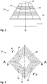
- Fig. 1 shows a cross section through an exhaust gas purification system 1 according to the invention.
- the exhaust gas flows in the vertical direction 6 via the inlet channel 5 from below into the preferably cuboid absorption space 3, which is delimited by the container wall 10. Compared to systems with a side entry, this results in a reduction in the footprint of the exhaust gas cleaning system, which depends to a large extent on the design of the laundry entry.
- the exhaust gas flows through the absorption space 3 from bottom to top and leaves it through the gas outlet 2.
- the opening 12 of the inlet channel 5 is covered by a pyramid-shaped roof attachment 13 with a square base.
- the gas distribution level 7, which consists of a large number of individual tubes 11, is located directly above the roof attachment 13. Due to the gas distribution plane 7, the exhaust gas is distributed more evenly within the absorption space 3 and, in addition, turbulence is induced in the flue gas, which leads to a more intensive mixing of the gas with the absorption solution.
- the absorption solution is introduced into the absorption space 3 via spray nozzles 20 of the spray levels 4 and comes into contact with the exhaust gas in the form of drops.
- the roof attachment 13 prevents the absorption solution from getting into the inlet channel 5 and thus into the exhaust tract.
- a rinsing device 8 and a droplet separator 9 are provided above the spray levels 4.
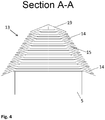
- the roof attachment 13 is shown in a side view. It consists of a plurality of lamellae 14 arranged one above the other, which are spaced apart from one another, so that the exhaust gas passes through the channels 15 formed between the lamellae 14 into the absorption space 3.
- the gas flow which initially runs vertically, is deflected in the distributor space within the roof attachment 13 in the direction of the lamellae 14 so that the passage areas are evenly loaded.
- the flanks of the roof attachment 13 are designed here to taper towards the top and meet at a point or in an auxiliary roof 19, which is small in terms of area. The primary aim of this arrangement is to maximize or optimize the passage area for the exhaust gas or flue gas flowing into the absorption space 3.
- the secondary aim of this arrangement compared to vertically arranged roof flanks is that the upwardly tapering roof attachment 13 provides additional space for the throughflow. Due to the enlargement of the freely flowable area, the exhaust gas or flue gas is braked directly after exiting the lamellas 14 and quickly deflected upwards. In contrast to the diversion with a Chinese hat, in which the flow rises unevenly in the form of strands, here the exhaust gas or flue gas rises unhindered in the sense of a plug flow.
- FIG. 3 a top view of the roof attachment 13 is shown.
- the struts 18 can be seen here, which connect the individual slats 14 at their outer ends, thereby preventing the slats 14 from fluttering.
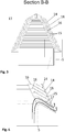
- FIG 6 shows a detailed view of the roof attachment 13 from Figure 5 .
- the lamellas 14 here have an arcuately curved starting area 16 in the direction of the gas inlet.
- the gas can flow evenly along the deflection between the individual lamellae 14 and a local breakdown or recirculation after the deflection is prevented.
- the gas flow is indicated by the two arrows 17. This optimized flow guidance minimizes the pressure loss significantly compared to the solution with a Chinese hat.
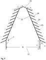
- Figure 7 shows a schematic view of the roof attachment 13 to illustrate individual dimensions and angles.
- the ratio between the cross-sectional area of the inlet channel 5 and the cross-sectional area of the absorption space 3 should be between 0.3 and 0.5.
- the side length of the square inlet channel 5 is here, for example, 1500 mm.
- the distance h of the lowermost lamella 14 from the scrubber floor is here 500 mm.
- the length y of the lamellae 14 and the lamellae spacing x are selected in such a way that the entry of drops against the outflow direction is prevented.
- the length y of the lamellae 14 is preferably between 150 and 300 mm, the lamellae spacing x being between 40 and 60 mm, preferably 50 mm.
- the slats 14 of the auxiliary roof 19 here have a length z of 290 mm.
- the angle of incidence ⁇ of the individual slats 14 based on a vertical should be 50 ° to 70 °, preferably 60 °. With regard to the pressure loss, this angle ⁇ was chosen so that the required deflection against the actual main flow direction is reduced to a minimum.
- the angle ⁇ of the sloping roof 21 should preferably be in the range from 140 ° to 170 ° with respect to a vertical, in particular 155 °.
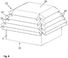
- FIG 8 a further embodiment of the roof attachment 13 according to the invention is shown.
- This roof attachment 13 has a square plan and has five slats 14 on each side. The top is closed by a flat auxiliary roof 19.
- FIG. 13 shows a sectional view through the roof attachment 13 from FIG Figure 8 .
- the shape of the lamellae 14 can be clearly seen here. Viewed in the direction of flow of the flue gas, the lamellae 14 have a vertical, straight starting area 16. This is followed by an arcuate section, which ultimately merges into a straight section that runs obliquely downwards. Due to this lamellar shape, the flue gas is deflected particularly gently in the channels 15. The gas flow 17 in the channels 15 is indicated by the two arrows. The uppermost slats 14 do not have a vertical or arched section, since they are connected directly to the auxiliary roof 19.
- the gas speed in the inlet channel 5 is 14-18 m / s, since significantly higher or lower flow speeds would lead to an inadequate flow distribution within the roof attachment 13.
- the gas velocity in the channels 15 should be in the range from 7 to 27 m / s.
Landscapes
- Engineering & Computer Science (AREA)
- Chemical & Material Sciences (AREA)
- Chemical Kinetics & Catalysis (AREA)
- Environmental & Geological Engineering (AREA)
- Oil, Petroleum & Natural Gas (AREA)
- General Chemical & Material Sciences (AREA)
- Analytical Chemistry (AREA)
- Mechanical Engineering (AREA)
- General Engineering & Computer Science (AREA)
- Combustion & Propulsion (AREA)
- Biomedical Technology (AREA)
- Health & Medical Sciences (AREA)
- Ocean & Marine Engineering (AREA)
- Treating Waste Gases (AREA)
- Gas Separation By Absorption (AREA)
Claims (8)
- Installation (1) d'absorption de différents composants tels que des polluants ou des substances valorisables dans des gaz, dans laquelle une solution d'absorption est mise en contact avec le gaz dans une chambre d'absorption (3), la solution d'absorption étant introduite par des buses de pulvérisation (20) d'un niveau de pulvérisation (4) dans la chambre d'absorption (3) et le gaz pouvant être acheminé par un canal d'entrée vertical (5) depuis le dessous dans la chambre d'absorption (3), le canal d'entrée (5) comportant un orifice (12), qui est recouvert d'un lanterneau (13), le plan du lanterneau (13) étant supérieur à celui de l'orifice d'admission (12) de manière à rendre impossible l'introduction de la solution d'absorption dans l'orifice d'admission (12), le lanterneau (13) étant composé d'une pluralité de lamelles (14) espacées les unes des autres et superposées les unes sur les autres, le lanterneau (13) étant fermé par un toit auxiliaire (19), caractérisée en ce que les lamelles (14) dans leur zone de commencement (16) sont arquées, ou en ce que les lamelles (14) dans leur zone de commencement (16) partent à la verticale vers le haut et ensuite sont arquées, aidant ainsi à faire dévier les gaz.
- Installation selon la revendication 1, caractérisée en ce que les lamelles (14) partent obliquement vers le bas vers la paroi de contenant (10) de la chambre d'absorption (3) de manière à ce que le gaz affluant verticalement soit dévié obliquement vers le bas, et puisse être acheminé par les canaux (15) formés entre les lamelles vers la chambre d'absorption (3).
- Installation selon la revendication 2, caractérisée en ce que l'angle α entre les lamelles (14) et les verticales est compris entre 50° et 70°, de préférence est égal à 60°.
- Installation selon la revendication 2 ou la revendication 3, caractérisée en ce que la longueur (y) des canaux (15) entre deux lamelles (14) est supérieure à la distance (x) entre les lamelles (14) formant les canaux (15).
- Installation selon l'une des revendications 1 à 4, caractérisée en ce que la pente (β) du bord de toit par rapport à une verticale est comprise entre 140° et 170°, de préférence est égale à 155°.
- Installation selon l'une des revendications 1 à 5, caractérisée en ce que les lamelles (14) forment un lanterneau (13) pyramidal.
- Installation selon l'une des revendications 1 à 5, caractérisée en ce que les lamelles (14) forment un lanterneau conique (13).
- Installation selon l'une des revendications 1 à 7, caractérisée en ce qu'au-dessus du lanterneau (13) est disposé un niveau de répartition de gaz (7) qui permet de générer des turbulences dans le flux de gaz acheminé.
Priority Applications (1)
| Application Number | Priority Date | Filing Date | Title |
|---|---|---|---|
| PL19156841T PL3556452T3 (pl) | 2018-04-19 | 2019-02-13 | Układ do absorpcji pojedynczych składników w gazach |
Applications Claiming Priority (1)
| Application Number | Priority Date | Filing Date | Title |
|---|---|---|---|
| ATA50330/2018A AT520534B1 (de) | 2018-04-19 | 2018-04-19 | Anlage zur Absorption von Einzelkomponenten aus Gasen |
Publications (2)
| Publication Number | Publication Date |
|---|---|
| EP3556452A1 EP3556452A1 (fr) | 2019-10-23 |
| EP3556452B1 true EP3556452B1 (fr) | 2021-03-31 |
Family
ID=65433542
Family Applications (1)
| Application Number | Title | Priority Date | Filing Date |
|---|---|---|---|
| EP19156841.9A Active EP3556452B1 (fr) | 2018-04-19 | 2019-02-13 | Installation d'absorption de composants individuels dans les gaz |
Country Status (5)
| Country | Link |
|---|---|
| US (1) | US11306643B2 (fr) |
| EP (1) | EP3556452B1 (fr) |
| CN (1) | CN110385016B (fr) |
| AT (1) | AT520534B1 (fr) |
| PL (1) | PL3556452T3 (fr) |
Families Citing this family (4)
| Publication number | Priority date | Publication date | Assignee | Title |
|---|---|---|---|---|
| AT523037B1 (de) * | 2020-02-07 | 2021-05-15 | Avl List Gmbh | Nasswäscher für gase |
| CN111804133A (zh) * | 2020-07-20 | 2020-10-23 | 中国船舶电站设备有限公司 | 一种船舶海水闭式脱硫系统 |
| CN113041750A (zh) * | 2021-02-07 | 2021-06-29 | 机械工业第九设计研究院有限公司 | 涂装车身立体库自动清洁系统 |
| CN113731132A (zh) * | 2021-08-05 | 2021-12-03 | 中石化宁波工程有限公司 | 一种用于烟气脱硫塔的高通气率气液分布器 |
Family Cites Families (26)
| Publication number | Priority date | Publication date | Assignee | Title |
|---|---|---|---|---|
| GB120304A (en) * | 1918-01-04 | 1918-11-07 | Robert Stuart Hilton | Improvements in and relating to Apparatus for Bringing Gases and Liquids into Intimate Contact. |
| JPS4631321B1 (fr) * | 1968-10-08 | 1971-09-11 | ||
| FR2215261A1 (en) * | 1973-01-26 | 1974-08-23 | Korvin Stanislas De | Air cleaner esp. for industrial fumes - combining cyclone, centrifugal, inertial and venturi scrubber sepn. methods in single unit |
| DE3222387A1 (de) * | 1982-06-15 | 1983-12-15 | G + H Montage Gmbh, 6700 Ludwigshafen | Abgaskanal, insbesondere mit eingebautem schalldaempfer aus mit mineralwolle gefuellten kulissen, sowie regenschutzvorrichtung hierfuer |
| DE9304777U1 (de) * | 1993-03-29 | 1994-06-09 | Dolata Tilo Dipl Ing | Vielzweck-Gaswäscher |
| CA2196217C (fr) | 1994-07-29 | 2000-11-28 | Hermann Bruggendick | Reacteur a adsorption utilise pour extraire les composants indesirables d'un fluide |
| AT402264B (de) * | 1995-09-07 | 1997-03-25 | Austrian Energy & Environment | Verfahren und einrichtung zur nassen abscheidung saurer gase |
| KR20010112081A (ko) * | 2001-06-02 | 2001-12-20 | 이동일 | 라멜라 분리기와 활성탄소섬유를 이용한 악취물질 제거장치 |
| US6868670B1 (en) * | 2003-02-28 | 2005-03-22 | Fleetguard, Inc. | Compact, reduced backpressure, vertical exhaust water trap assembly |
| DE10320079A1 (de) * | 2003-05-05 | 2004-12-02 | BSH Bosch und Siemens Hausgeräte GmbH | Ausblasfilter mit Luftleitdach |
| CN101288823B (zh) * | 2008-06-13 | 2010-08-25 | 武汉晶源环境工程有限责任公司 | 一种海船排烟洗涤装置及洗涤方法 |
| CN101362043B (zh) * | 2008-09-19 | 2010-12-22 | 姚立猛 | 工业炉窑脱硫除尘方法 |
| CN201988311U (zh) * | 2010-12-20 | 2011-09-28 | 詹清光 | 废气处理装置 |
| WO2012105905A1 (fr) | 2011-01-31 | 2012-08-09 | Viridis Harbour Inc. | Appareil et procédé d'élimination ou de réduction de polluants gazeux de courant de gaz d'échappement |
| CN103688031B (zh) * | 2011-07-01 | 2018-03-27 | 彭斯干 | 一种优化内燃机排气背压的方法、装置和系统 |
| AT512543B1 (de) * | 2012-07-17 | 2013-09-15 | Andritz Energy & Environment Gmbh | Anlage und Verfahren zur Absorption von Einzelkomponenten in Gasen |
| KR101448459B1 (ko) * | 2012-12-07 | 2014-10-08 | 주식회사 포스코플랜텍 | 흡수탑 |
| CN103041687B (zh) * | 2012-12-18 | 2015-05-06 | 北京威肯众合环保科技有限公司 | 一种集除尘、消烟、脱硫为一体的油炉烟气净化复合塔 |
| NO335786B1 (no) * | 2013-02-22 | 2015-02-16 | Marine Global Holding As | Marin eksosgassrensing |
| KR101608720B1 (ko) * | 2015-02-27 | 2016-04-04 | 부경대학교 산학협력단 | 배기가스 정화장치 |
| AT14588U1 (de) * | 2015-03-05 | 2016-02-15 | Andritz Ag Maschf | Abhebevorrichtung für Gasverteilungsmodule |
| CN205495321U (zh) * | 2016-04-08 | 2016-08-24 | 浙江科技学院 | 除尘脱硫塔 |
| FR3050654B1 (fr) * | 2016-04-27 | 2021-02-12 | Lab Sa | Procede et installation d'epuration par voie humide des fumees d'echappement d'un moteur d'un navire marin |
| FR3051436B1 (fr) * | 2016-05-17 | 2018-06-22 | Lab Sa | Dispositif d'introduction de fumees d'echappement d'un moteur de navire marin dans un laveur |
| EP3260187A1 (fr) | 2016-06-23 | 2017-12-27 | Yara Marine Technologies AS | Système et procédé permettant de réduire la quantité d'oxydes de soufre dans les gaz d'échappement |
| CN106512641A (zh) * | 2016-12-03 | 2017-03-22 | 福建众辉环保设备有限公司 | 一种有机废气净化装置 |
-
2018
- 2018-04-19 AT ATA50330/2018A patent/AT520534B1/de active
-
2019
- 2019-02-13 EP EP19156841.9A patent/EP3556452B1/fr active Active
- 2019-02-13 PL PL19156841T patent/PL3556452T3/pl unknown
- 2019-04-04 US US16/375,226 patent/US11306643B2/en active Active
- 2019-04-18 CN CN201910315276.1A patent/CN110385016B/zh active Active
Non-Patent Citations (1)
| Title |
|---|
| None * |
Also Published As
| Publication number | Publication date |
|---|---|
| AT520534B1 (de) | 2019-05-15 |
| US11306643B2 (en) | 2022-04-19 |
| US20190323409A1 (en) | 2019-10-24 |
| EP3556452A1 (fr) | 2019-10-23 |
| AT520534A4 (de) | 2019-05-15 |
| CN110385016B (zh) | 2022-05-10 |
| PL3556452T3 (pl) | 2021-11-22 |
| CN110385016A (zh) | 2019-10-29 |
Similar Documents
| Publication | Publication Date | Title |
|---|---|---|
| EP3556452B1 (fr) | Installation d'absorption de composants individuels dans les gaz | |
| DE4214094C1 (fr) | ||
| DE69828815T2 (de) | Gas-flüssigkeit-kontaktapparat mit einer flüssigkeits-wiederverteilungsvorrichtung | |
| DE112007000786T5 (de) | Rauchgas-Nassentschwefler | |
| DE2301469C3 (de) | Gaswäscher | |
| DE2725119C2 (de) | Separatorvorrichtung für Eindampfanlagen | |
| DE2246474A1 (de) | Vorrichtung zum waschen von gasen | |
| DE102006004069A1 (de) | Verfahren und Vorrichtung zum Vermischen eines Fluids mit einem großen Gasmengenstrom | |
| DE2526686A1 (de) | Ablenkplatte fuer waermeaustauschanlage | |
| EP1981622B2 (fr) | Procédé et dispositif pour mélanger un fluide gazeux à un flux gazeux important, notamment pour introduire un agent réducteur dans un gaz de combustion contenant des oxydes d'azote | |
| DE69820597T2 (de) | Offener kontaktreaktor | |
| DE3612218C1 (en) | Apparatus for uniformly impinging a catalyst bed with an exhaust gas to be purified | |
| DE3410110C2 (fr) | ||
| DE3634126A1 (de) | Waschturm mit einem waschturmmantel fuer eine anlage zur entschwefelung von rauchgas | |
| EP0310830B1 (fr) | Refroidisseur du type venturi pour une installation de désulfuration de fumées | |
| DE4344535C2 (de) | Reaktor für katalytische Gasphasenreaktionen mit einem Gaseinleitungsbereich und Verwendung zur katalytischen Behandlung von Abgas | |
| DE102009022673B4 (de) | Verteileinrichtung für einen Fluidstrom | |
| EP3204151B1 (fr) | Bassin d'oxydation et procédé de traitement de l'eau de décharge d'un dispositif d'épuration d'effluents gazeux à l'eau de mer | |
| EP0233998A1 (fr) | Dispositif de réglage à une valeur donnée de la température des fumées | |
| DE3436833A1 (de) | Entluefter fuer wasserumlaufsysteme | |
| DE202007007744U1 (de) | Kühlturm mit Reingasabführung | |
| EP0565886B1 (fr) | Cheminée industrielle avec dispositif de protection contre l'acide | |
| DE3004241A1 (de) | Vorrichtung zum abscheiden von fluessigkeitstropfen aus gasen | |
| DE620262C (de) | Saugaufsatz fuer Rauch- und Entlueftungskamine | |
| DE1571767C (de) | Gaswaschturm |
Legal Events
| Date | Code | Title | Description |
|---|---|---|---|
| PUAI | Public reference made under article 153(3) epc to a published international application that has entered the european phase |
Free format text: ORIGINAL CODE: 0009012 |
|
| STAA | Information on the status of an ep patent application or granted ep patent |
Free format text: STATUS: THE APPLICATION HAS BEEN PUBLISHED |
|
| AK | Designated contracting states |
Kind code of ref document: A1 Designated state(s): AL AT BE BG CH CY CZ DE DK EE ES FI FR GB GR HR HU IE IS IT LI LT LU LV MC MK MT NL NO PL PT RO RS SE SI SK SM TR |
|
| AX | Request for extension of the european patent |
Extension state: BA ME |
|
| STAA | Information on the status of an ep patent application or granted ep patent |
Free format text: STATUS: REQUEST FOR EXAMINATION WAS MADE |
|
| 17P | Request for examination filed |
Effective date: 20200317 |
|
| RBV | Designated contracting states (corrected) |
Designated state(s): AL AT BE BG CH CY CZ DE DK EE ES FI FR GB GR HR HU IE IS IT LI LT LU LV MC MK MT NL NO PL PT RO RS SE SI SK SM TR |
|
| GRAP | Despatch of communication of intention to grant a patent |
Free format text: ORIGINAL CODE: EPIDOSNIGR1 |
|
| STAA | Information on the status of an ep patent application or granted ep patent |
Free format text: STATUS: GRANT OF PATENT IS INTENDED |
|
| INTG | Intention to grant announced |
Effective date: 20201223 |
|
| GRAS | Grant fee paid |
Free format text: ORIGINAL CODE: EPIDOSNIGR3 |
|
| GRAA | (expected) grant |
Free format text: ORIGINAL CODE: 0009210 |
|
| STAA | Information on the status of an ep patent application or granted ep patent |
Free format text: STATUS: THE PATENT HAS BEEN GRANTED |
|
| AK | Designated contracting states |
Kind code of ref document: B1 Designated state(s): AL AT BE BG CH CY CZ DE DK EE ES FI FR GB GR HR HU IE IS IT LI LT LU LV MC MK MT NL NO PL PT RO RS SE SI SK SM TR |
|
| REG | Reference to a national code |
Ref country code: GB Ref legal event code: FG4D Free format text: NOT ENGLISH Ref country code: CH Ref legal event code: EP |
|
| REG | Reference to a national code |
Ref country code: AT Ref legal event code: REF Ref document number: 1376296 Country of ref document: AT Kind code of ref document: T Effective date: 20210415 |
|
| REG | Reference to a national code |
Ref country code: DE Ref legal event code: R096 Ref document number: 502019001071 Country of ref document: DE |
|
| REG | Reference to a national code |
Ref country code: IE Ref legal event code: FG4D Free format text: LANGUAGE OF EP DOCUMENT: GERMAN |
|
| REG | Reference to a national code |
Ref country code: NL Ref legal event code: FP |
|
| REG | Reference to a national code |
Ref country code: LT Ref legal event code: MG9D |
|
| PG25 | Lapsed in a contracting state [announced via postgrant information from national office to epo] |
Ref country code: BG Free format text: LAPSE BECAUSE OF FAILURE TO SUBMIT A TRANSLATION OF THE DESCRIPTION OR TO PAY THE FEE WITHIN THE PRESCRIBED TIME-LIMIT Effective date: 20210630 Ref country code: HR Free format text: LAPSE BECAUSE OF FAILURE TO SUBMIT A TRANSLATION OF THE DESCRIPTION OR TO PAY THE FEE WITHIN THE PRESCRIBED TIME-LIMIT Effective date: 20210331 Ref country code: FI Free format text: LAPSE BECAUSE OF FAILURE TO SUBMIT A TRANSLATION OF THE DESCRIPTION OR TO PAY THE FEE WITHIN THE PRESCRIBED TIME-LIMIT Effective date: 20210331 Ref country code: NO Free format text: LAPSE BECAUSE OF FAILURE TO SUBMIT A TRANSLATION OF THE DESCRIPTION OR TO PAY THE FEE WITHIN THE PRESCRIBED TIME-LIMIT Effective date: 20210630 |
|
| PG25 | Lapsed in a contracting state [announced via postgrant information from national office to epo] |
Ref country code: SE Free format text: LAPSE BECAUSE OF FAILURE TO SUBMIT A TRANSLATION OF THE DESCRIPTION OR TO PAY THE FEE WITHIN THE PRESCRIBED TIME-LIMIT Effective date: 20210331 Ref country code: LV Free format text: LAPSE BECAUSE OF FAILURE TO SUBMIT A TRANSLATION OF THE DESCRIPTION OR TO PAY THE FEE WITHIN THE PRESCRIBED TIME-LIMIT Effective date: 20210331 Ref country code: RS Free format text: LAPSE BECAUSE OF FAILURE TO SUBMIT A TRANSLATION OF THE DESCRIPTION OR TO PAY THE FEE WITHIN THE PRESCRIBED TIME-LIMIT Effective date: 20210331 |
|
| REG | Reference to a national code |
Ref country code: GR Ref legal event code: EP Ref document number: 20210401683 Country of ref document: GR Effective date: 20210813 |
|
| PG25 | Lapsed in a contracting state [announced via postgrant information from national office to epo] |
Ref country code: SM Free format text: LAPSE BECAUSE OF FAILURE TO SUBMIT A TRANSLATION OF THE DESCRIPTION OR TO PAY THE FEE WITHIN THE PRESCRIBED TIME-LIMIT Effective date: 20210331 Ref country code: LT Free format text: LAPSE BECAUSE OF FAILURE TO SUBMIT A TRANSLATION OF THE DESCRIPTION OR TO PAY THE FEE WITHIN THE PRESCRIBED TIME-LIMIT Effective date: 20210331 Ref country code: CZ Free format text: LAPSE BECAUSE OF FAILURE TO SUBMIT A TRANSLATION OF THE DESCRIPTION OR TO PAY THE FEE WITHIN THE PRESCRIBED TIME-LIMIT Effective date: 20210331 Ref country code: EE Free format text: LAPSE BECAUSE OF FAILURE TO SUBMIT A TRANSLATION OF THE DESCRIPTION OR TO PAY THE FEE WITHIN THE PRESCRIBED TIME-LIMIT Effective date: 20210331 |
|
| PG25 | Lapsed in a contracting state [announced via postgrant information from national office to epo] |
Ref country code: IS Free format text: LAPSE BECAUSE OF FAILURE TO SUBMIT A TRANSLATION OF THE DESCRIPTION OR TO PAY THE FEE WITHIN THE PRESCRIBED TIME-LIMIT Effective date: 20210731 Ref country code: SK Free format text: LAPSE BECAUSE OF FAILURE TO SUBMIT A TRANSLATION OF THE DESCRIPTION OR TO PAY THE FEE WITHIN THE PRESCRIBED TIME-LIMIT Effective date: 20210331 Ref country code: RO Free format text: LAPSE BECAUSE OF FAILURE TO SUBMIT A TRANSLATION OF THE DESCRIPTION OR TO PAY THE FEE WITHIN THE PRESCRIBED TIME-LIMIT Effective date: 20210331 Ref country code: PT Free format text: LAPSE BECAUSE OF FAILURE TO SUBMIT A TRANSLATION OF THE DESCRIPTION OR TO PAY THE FEE WITHIN THE PRESCRIBED TIME-LIMIT Effective date: 20210802 |
|
| REG | Reference to a national code |
Ref country code: DE Ref legal event code: R097 Ref document number: 502019001071 Country of ref document: DE |
|
| PG25 | Lapsed in a contracting state [announced via postgrant information from national office to epo] |
Ref country code: AL Free format text: LAPSE BECAUSE OF FAILURE TO SUBMIT A TRANSLATION OF THE DESCRIPTION OR TO PAY THE FEE WITHIN THE PRESCRIBED TIME-LIMIT Effective date: 20210331 Ref country code: DK Free format text: LAPSE BECAUSE OF FAILURE TO SUBMIT A TRANSLATION OF THE DESCRIPTION OR TO PAY THE FEE WITHIN THE PRESCRIBED TIME-LIMIT Effective date: 20210331 Ref country code: ES Free format text: LAPSE BECAUSE OF FAILURE TO SUBMIT A TRANSLATION OF THE DESCRIPTION OR TO PAY THE FEE WITHIN THE PRESCRIBED TIME-LIMIT Effective date: 20210331 |
|
| PLBE | No opposition filed within time limit |
Free format text: ORIGINAL CODE: 0009261 |
|
| STAA | Information on the status of an ep patent application or granted ep patent |
Free format text: STATUS: NO OPPOSITION FILED WITHIN TIME LIMIT |
|
| 26N | No opposition filed |
Effective date: 20220104 |
|
| PG25 | Lapsed in a contracting state [announced via postgrant information from national office to epo] |
Ref country code: IS Free format text: LAPSE BECAUSE OF FAILURE TO SUBMIT A TRANSLATION OF THE DESCRIPTION OR TO PAY THE FEE WITHIN THE PRESCRIBED TIME-LIMIT Effective date: 20210731 |
|
| PG25 | Lapsed in a contracting state [announced via postgrant information from national office to epo] |
Ref country code: MC Free format text: LAPSE BECAUSE OF FAILURE TO SUBMIT A TRANSLATION OF THE DESCRIPTION OR TO PAY THE FEE WITHIN THE PRESCRIBED TIME-LIMIT Effective date: 20210331 |
|
| REG | Reference to a national code |
Ref country code: CH Ref legal event code: PL |
|
| REG | Reference to a national code |
Ref country code: BE Ref legal event code: MM Effective date: 20220228 |
|
| PG25 | Lapsed in a contracting state [announced via postgrant information from national office to epo] |
Ref country code: LU Free format text: LAPSE BECAUSE OF NON-PAYMENT OF DUE FEES Effective date: 20220213 |
|
| PG25 | Lapsed in a contracting state [announced via postgrant information from national office to epo] |
Ref country code: FR Free format text: LAPSE BECAUSE OF NON-PAYMENT OF DUE FEES Effective date: 20220228 |
|
| PG25 | Lapsed in a contracting state [announced via postgrant information from national office to epo] |
Ref country code: LI Free format text: LAPSE BECAUSE OF NON-PAYMENT OF DUE FEES Effective date: 20220228 Ref country code: IE Free format text: LAPSE BECAUSE OF NON-PAYMENT OF DUE FEES Effective date: 20220213 Ref country code: CH Free format text: LAPSE BECAUSE OF NON-PAYMENT OF DUE FEES Effective date: 20220228 |
|
| PG25 | Lapsed in a contracting state [announced via postgrant information from national office to epo] |
Ref country code: BE Free format text: LAPSE BECAUSE OF NON-PAYMENT OF DUE FEES Effective date: 20220228 |
|
| PGFP | Annual fee paid to national office [announced via postgrant information from national office to epo] |
Ref country code: NL Payment date: 20230216 Year of fee payment: 5 |
|
| PGFP | Annual fee paid to national office [announced via postgrant information from national office to epo] |
Ref country code: PL Payment date: 20230206 Year of fee payment: 5 Ref country code: IT Payment date: 20230223 Year of fee payment: 5 Ref country code: GR Payment date: 20230220 Year of fee payment: 5 Ref country code: DE Payment date: 20230216 Year of fee payment: 5 |
|
| GBPC | Gb: european patent ceased through non-payment of renewal fee |
Effective date: 20230213 |
|
| PG25 | Lapsed in a contracting state [announced via postgrant information from national office to epo] |
Ref country code: GB Free format text: LAPSE BECAUSE OF NON-PAYMENT OF DUE FEES Effective date: 20230213 |
|
| PG25 | Lapsed in a contracting state [announced via postgrant information from national office to epo] |
Ref country code: GB Free format text: LAPSE BECAUSE OF NON-PAYMENT OF DUE FEES Effective date: 20230213 |
|
| PG25 | Lapsed in a contracting state [announced via postgrant information from national office to epo] |
Ref country code: MK Free format text: LAPSE BECAUSE OF FAILURE TO SUBMIT A TRANSLATION OF THE DESCRIPTION OR TO PAY THE FEE WITHIN THE PRESCRIBED TIME-LIMIT Effective date: 20210331 Ref country code: CY Free format text: LAPSE BECAUSE OF FAILURE TO SUBMIT A TRANSLATION OF THE DESCRIPTION OR TO PAY THE FEE WITHIN THE PRESCRIBED TIME-LIMIT Effective date: 20210331 |