EP3555899B1 - Stromkontaktor und fahrzeug mit solch einem kontaktor - Google Patents
Stromkontaktor und fahrzeug mit solch einem kontaktor Download PDFInfo
- Publication number
- EP3555899B1 EP3555899B1 EP17822005.9A EP17822005A EP3555899B1 EP 3555899 B1 EP3555899 B1 EP 3555899B1 EP 17822005 A EP17822005 A EP 17822005A EP 3555899 B1 EP3555899 B1 EP 3555899B1
- Authority
- EP
- European Patent Office
- Prior art keywords
- ground plane
- electrical ground
- electrical power
- electrical
- contactor
- Prior art date
- Legal status (The legal status is an assumption and is not a legal conclusion. Google has not performed a legal analysis and makes no representation as to the accuracy of the status listed.)
- Active
Links
Images



Classifications
-
- H—ELECTRICITY
- H01—ELECTRIC ELEMENTS
- H01H—ELECTRIC SWITCHES; RELAYS; SELECTORS; EMERGENCY PROTECTIVE DEVICES
- H01H9/00—Details of switching devices, not covered by groups H01H1/00 - H01H7/00
- H01H9/54—Circuit arrangements not adapted to a particular application of the switching device and for which no provision exists elsewhere
-
- B—PERFORMING OPERATIONS; TRANSPORTING
- B64—AIRCRAFT; AVIATION; COSMONAUTICS
- B64D—EQUIPMENT FOR FITTING IN OR TO AIRCRAFT; FLIGHT SUITS; PARACHUTES; ARRANGEMENT OR MOUNTING OF POWER PLANTS OR PROPULSION TRANSMISSIONS IN AIRCRAFT
- B64D41/00—Power installations for auxiliary purposes
-
- H—ELECTRICITY
- H01—ELECTRIC ELEMENTS
- H01H—ELECTRIC SWITCHES; RELAYS; SELECTORS; EMERGENCY PROTECTIVE DEVICES
- H01H47/00—Circuit arrangements not adapted to a particular application of the relay and designed to obtain desired operating characteristics or to provide energising current
-
- H—ELECTRICITY
- H01—ELECTRIC ELEMENTS
- H01H—ELECTRIC SWITCHES; RELAYS; SELECTORS; EMERGENCY PROTECTIVE DEVICES
- H01H47/00—Circuit arrangements not adapted to a particular application of the relay and designed to obtain desired operating characteristics or to provide energising current
- H01H47/22—Circuit arrangements not adapted to a particular application of the relay and designed to obtain desired operating characteristics or to provide energising current for supplying energising current for relay coil
-
- H—ELECTRICITY
- H01—ELECTRIC ELEMENTS
- H01H—ELECTRIC SWITCHES; RELAYS; SELECTORS; EMERGENCY PROTECTIVE DEVICES
- H01H50/00—Details of electromagnetic relays
- H01H50/02—Bases; Casings; Covers
- H01H50/04—Mounting complete relay or separate parts of relay on a base or inside a case
- H01H50/041—Details concerning assembly of relays
- H01H50/045—Details particular to contactors
-
- H—ELECTRICITY
- H01—ELECTRIC ELEMENTS
- H01H—ELECTRIC SWITCHES; RELAYS; SELECTORS; EMERGENCY PROTECTIVE DEVICES
- H01H50/00—Details of electromagnetic relays
- H01H50/54—Contact arrangements
- H01H50/541—Auxiliary contact devices
-
- H—ELECTRICITY
- H01—ELECTRIC ELEMENTS
- H01H—ELECTRIC SWITCHES; RELAYS; SELECTORS; EMERGENCY PROTECTIVE DEVICES
- H01H9/00—Details of switching devices, not covered by groups H01H1/00 - H01H7/00
- H01H9/12—Means for earthing parts of switch not normally conductively connected to the contacts
-
- B—PERFORMING OPERATIONS; TRANSPORTING
- B64—AIRCRAFT; AVIATION; COSMONAUTICS
- B64D—EQUIPMENT FOR FITTING IN OR TO AIRCRAFT; FLIGHT SUITS; PARACHUTES; ARRANGEMENT OR MOUNTING OF POWER PLANTS OR PROPULSION TRANSMISSIONS IN AIRCRAFT
- B64D2221/00—Electric power distribution systems onboard aircraft
Definitions
- the invention belongs to the field of power supply distribution networks.
- the invention belongs to the field of the distribution of electrical power on board in vehicles.
- the invention relates to an electrical power contactor, for example a contactor used in an aircraft.
- the return of the currents carried by the phases or the positive of the power supply is generally carried out by a separate dedicated conductor, neutral or potential with reference to the power supply, distinctly with respect to the electrical mass of the vehicle structure.
- This configuration illustrated in the example of installation of a contactor 100 illustrated on the Figure 1 is used in particular when the qualities required for the equipment supply circuits are incompatible with a nominal current return by the structure of the vehicle used as electrical ground.
- Such a configuration involves a large number of component / component and component / system interfaces, leading to a complexity and a weight of wiring as well as risks of electromagnetic coupling due to radiating radiofrequency current loops.
- the invention proposes an electrical power contactor reducing the complexity of the internal wiring, thus making it possible to limit the consequences of the problem mentioned above and to improve the reliability of the installation.
- the document FR 2 820 900 A1 discloses an electrical power contactor according to the preamble of claim 1.
- the at least one power contact, the at least one coil and the at least one auxiliary contact are enclosed in a mechanical housing.
- the electrical power contactor further comprises a local electrical ground plane intended to be electrically connected to the reference potential OVdc of the electrical power supply and to an electrical ground external to the electrical power contactor.
- a current return from the at least one controller is connected to the local electrical ground plane.
- the mechanical housing is connected to the local electrical ground plane by an independent conductor.
- the mechanical housing is connected to the local electrical ground plane by the common conductor connecting the current returns of the at least one coil and of the at least one auxiliary contact to said local electrical ground plane.
- a distance from the local electrical ground plane to the at least one controller and a distance from the local electrical ground plane to a mechanical housing comprising the switching elements is less than or equal to 30 cm.
- the resistance between any two points of the local electrical mass plane is less than 10 ⁇ , preferably 2 ⁇ .
- the local electrical ground plane is a rectangular plate of a material of resistivity less than or equal to 10 -6 ⁇ .m, of thickness e greater than or equal to 0.10 mm, preferably equal to 0 , 5mm, and whose ratio l / L of a plate width l over a length L of plate is greater than or equal to 2/3 and less than or equal to 1.
- the local electrical ground plane has a substantially square shape.
- the invention also relates to an aircraft comprising at least one electrical power contactor according to the invention.
- the aircraft further comprises a general electrical ground plane in charge of the aircraft current returns and to which the local electrical ground plane of the at least one power contactor is connected.
- the Figure 1 shows the wiring diagram of a contactor 100 of the prior art, conventionally used in an on-board electrical system of an aircraft.
- the inrush current likely to pass through the inrush L2 and holding L1 + L2 coils to close the power contact 111 is sometimes ten times greater than the holding current likely to pass through the L1 + L2 holding coil to keep the said contact closed. power contact.
- the inrush current may be 4A, and the holding current of 0.4A, which justifies the use of two coils to limit the electrical consumption and the heating over long periods of excitation of the power contactor.
- a contactor which can have several power contacts, normally open or normally closed, and a different number of secondary contacts normally open or normally closed.
- Terminals 1 to 11 are electrically and individually connected to the controller 120.
- the mechanical box 110 containing in particular the switching elements, that is to say the coils and the auxiliary contacts, is also connected to an electrical ground 310 by a grounding conductor 113 so as to convey the currents of leak and avoid an accumulation of electric charges on said housing implemented with electromagnetic shielding.
- the controller 120 is in turn supplied with voltage by an electrical supply 300 having a supply potential + Vdc and a potential reference 0Vdc.
- the power contactor 100 comprises six returns to the reference potential 0Vdc.
- the local electrical ground plane 230 is made of an electrically good conductive material, for example copper.
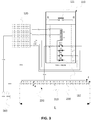
- connections to the reference potential 0Vdc associated with the coils L1, L2 and the auxiliary contactors of the power contactor 200 are grouped, inside the mechanical housing 110 of said contactor, as close as possible to the auxiliary contacts and the coils L1, L2 on a single 3 'connection terminal.
- a single common conductor for example an electric cable, is used to connect the connection terminal 3 'to the local electrical ground plane 230.
- the controller 120 and the mechanical housing 110 are connected independently of said common conductor to said electrical ground plane local.
- the local electrical ground plane 230 has substantially the shape of a rectangular plate, of minimum thickness e 0.1 mm and preferably equal to 0.5 mm, and of length L and width l such that a ratio l / L is greater than two thirds and less than or equal to 1.
- the plate is substantially square.
- Such characteristics make it possible to obtain a resistance, between any two points of the electrical ground plane, sufficiently low to reduce the risk of disturbances by common impedance when several signals share the same return electrical mass at a level compatible with the requirements of the equipment. on board.
- the use of a plate in favor of a braid makes it possible to limit the number of multi-contact connections, thus avoiding increases in electrical resistance locally, at the connection points, and also avoiding a deterioration in the reliability of the electrical system.
- the term "sufficiently low resistance” means a resistance of less than 10 ⁇ , preferably less than 2 ⁇ .
- the at least one electrical ground plane 230 may be made of a material that is a good electrical conductor, for example copper.
- the expression “good conductive material” must be understood in the sense commonly understood by a person skilled in the art of electrical power distribution systems. In general, a material having a resistivity of less than 10 -6 ⁇ .m under the conditions of use is considered to be “good conductor”.
- the local electrical ground plane 230 is located as close as possible to the mechanical housing 110 and the controller 120, so as to limit the length of the cables used, and therefore their weight.
- the arrangement of the local electrical ground plane 230 is such that the conductive cables used to connect the connection terminal 3 ', the mechanical box 110 and the controller 120 have a length of less than 30 cm.
- the local electrical ground plane 230 of a contactor according to the invention can serve as a local electrical ground plane 230 for another contactor 200 according to the invention, in particular in the environment of an electrical cabinet comprising a plurality of electrical contactors.
- the single common conductor used to connect the connection terminal 3 'to the local electrical ground plane 230 is also used to connect the mechanical housing 110 to said local electrical ground plane.
- the assembly according to the invention therefore allows the internal wiring of the power contactor 200 using the local electrical ground plane 230.
- the limitation of the number of cables makes it possible to limit, by about 30% in practice, the weight of wiring implemented in the contactor 200, and to minimize the radiating radiofrequency current loops, thus reducing the risks of electromagnetic coupling which can induce electrical system malfunctions.
- the invention as described here is suitable for any type of vehicle, and particularly for aircraft with a structure mainly made of composite materials. Indeed, such aircraft are provided with a general electric ground plane 400 because the leakage currents, always possible, are liable to damage said structure.
- the electrical power contactor 200 according to the invention can be advantageously implemented in such an aircraft, the electrical ground plane of which acts as the general electrical ground plane 400 as illustrated in the Figure 4 to which the reference potential of the local ground plane 230 is related via the power supply 300.
- the electric ground 310 of the embodiment of the Figure 2 is here advantageously replaced by the general electric ground plane 400.
- the invention is not limited to the sole field of aeronautics of the embodiment detailed here, but could be adapted to other industrial fields such as for example the automotive field.
Landscapes
- Physics & Mathematics (AREA)
- Electromagnetism (AREA)
- Engineering & Computer Science (AREA)
- Aviation & Aerospace Engineering (AREA)
- Electric Propulsion And Braking For Vehicles (AREA)
- Coupling Device And Connection With Printed Circuit (AREA)
- Emergency Protection Circuit Devices (AREA)
Claims (9)
- Elektrisches Leistungsschütz (200) zur Verbindung mit einer Gleichstromversorgung (300) die eine Potentialdifferenz zwischen einem Anschluss mit einem Potential Vdc und einem Anschluss mit einem Referenzpotential 0Vdc aufrechterhält, wobei das elektrische Schütz Folgendes aufweist:- mindestens eine Spule (L1; L2) die angeordnet ist, mindestens einen Leistungskontakt (111) zu betätigen; und- mindestens eine Steuerung (120), die die mindestens eine Spule mit einer Spannung +Vdc versorgt, die von der Stromversorgung (300) bereitgestellt wird; und- mindestens einen Hilfskontakt (112), der durch die mindestens eine Spule betätigt wird, wobei ein Anschluss des mindestens einen Hilfskontakts mit einem Eingang der Steuerung verbunden ist, um eine Spannung an dem Eingang zu definieren;wobei der mindestens eine Leistungskontakt (111), die mindestens eine Spule (L1; L2) und der mindestens eine Hilfskontakt (112) in einem mechanischen Gehäuse (110) eingeschlossen sind, wobei das elektrische Schütz dadurch gekennzeichnet ist, dass:- das elektrische Leistungsschütz (200) ferner eine lokale elektrische Massefläche (230) aufweist, die dazu bestimmt ist, mit dem Referenzpotential 0Vdc der Stromversorgung (300) und einer elektrischen Masse (310), die sich außerhalb des elektrischen Leistungsschützes (200) befindet, elektrisch verbunden zu sein;- Stromrückführungen von der mindestens einen Spule (L1; L2) und dem mindestens einen Hilfskontakt (112) durch einen gemeinsamen Leiter realisiert sind, der mit der lokalen elektrischen Massefläche verbunden ist;- eine Stromrückführung von der mindestens einen Steuerung (120) mit der lokalen elektrischen Massefläche verbunden ist.
- Elektrisches Leistungsschütz (200) nach Anspruch 1, dadurch gekennzeichnet, dass das mechanische Gehäuse (110) durch einen unabhängigen Leiter mit der lokalen elektrischen Massefläche (230) verbunden ist.
- Elektrisches Leistungsschütz (200) nach Anspruch 1 dadurch gekennzeichnet, dass das mechanische Gehäuse (110) durch den gemeinsamen Leiter mit der lokalen elektrischen Massefläche (230) verbunden ist, der die Stromrückführungen von der mindestens einen Spule (L1; L2) und von dem mindestens einen Hilfskontakt mit der lokalen elektrischen Massefläche (230) verbindet.
- Elektrisches Leistungsschütz (200) nach einem der vorhergehenden Ansprüche, dadurch gekennzeichnet, dass ein Abstand von der lokalen elektrischen Massefläche (230) zu der mindestens einen Steuerung (120) und ein Abstand von der lokalen elektrischen Massefläche (230) zu einem mechanischen Gehäuse (110), das die Schaltelemente umfasst, kleiner als oder gleich 30 cm ist.
- Elektrisches Leistungsschütz (200) nach einem der vorhergehenden Ansprüche, dadurch gekennzeichnet, dass der Widerstand zwischen zwei beliebigen Punkten der lokalen elektrischen Massefläche (230) weniger als 10 µΩ, vorzugsweise weniger als 2 µΩ beträgt.
- Elektrisches Leistungsschütz (200) nach einem der vorhergehenden Ansprüche, dadurch gekennzeichnet, dass die lokale elektrische Massefläche (230) eine rechteckige Platte aus einem Material mit einer Resistivität kleiner als oder gleich 10-6 Ω.m, einer Dicke e größer als oder gleich 0,10 mm, vorzugsweise gleich à 0,5mm ist, und wovon ein Verhältnis ℓ/L einer Plattenbreite ℓ zu einer Plattenlänge L größer als oder gleich 2/3 und kleiner als oder gleich 1 ist.
- Elektrisches Leistungsschütz (200) nach Anspruch 6, dadurch gekennzeichnet, dass die lokale elektrische Massefläche (230) eine im Wesentlichen quadratische Form aufweist.
- Luftfahrzeug aufweisend mindestens ein elektrisches Leistungsschütz (200) nach einem der vorhergehenden Ansprüche.
- Luftfahrzeug nach Anspruch 8, ferner aufweisend eine allgemeine elektrische Massefläche (400), die für die Stromrückführungen des Luftfahrzeugs zuständig sind, und mit der die lokale elektrische Massefläche (230) des mindestens einen Leistungsschützes (200) verbunden ist.
Applications Claiming Priority (2)
| Application Number | Priority Date | Filing Date | Title |
|---|---|---|---|
| FR1662604A FR3060832B1 (fr) | 2016-12-16 | 2016-12-16 | Contacteur electrique de puissance et vehicule comportant un tel contacteur |
| PCT/FR2017/053578 WO2018109404A1 (fr) | 2016-12-16 | 2017-12-14 | Contacteur électrique de puissance et véhicule comportant un tel contacteur |
Publications (2)
| Publication Number | Publication Date |
|---|---|
| EP3555899A1 EP3555899A1 (de) | 2019-10-23 |
| EP3555899B1 true EP3555899B1 (de) | 2020-04-15 |
Family
ID=58347586
Family Applications (1)
| Application Number | Title | Priority Date | Filing Date |
|---|---|---|---|
| EP17822005.9A Active EP3555899B1 (de) | 2016-12-16 | 2017-12-14 | Stromkontaktor und fahrzeug mit solch einem kontaktor |
Country Status (5)
| Country | Link |
|---|---|
| US (1) | US11251006B2 (de) |
| EP (1) | EP3555899B1 (de) |
| CN (1) | CN110168689B (de) |
| FR (1) | FR3060832B1 (de) |
| WO (1) | WO2018109404A1 (de) |
Family Cites Families (11)
| Publication number | Priority date | Publication date | Assignee | Title |
|---|---|---|---|---|
| US2821666A (en) * | 1954-02-19 | 1958-01-28 | Westinghouse Electric Corp | Control and protection of electric power systems |
| DE2103292A1 (de) * | 1971-01-25 | 1972-08-17 | Jager P De | Magnetschalter |
| US5301083A (en) * | 1991-09-30 | 1994-04-05 | Eaton Corporation | Remote control residential circuit breaker |
| FR2820900B1 (fr) * | 2001-02-09 | 2003-04-04 | Schneider Electric Ind Sa | Dispositif de depart-moteur |
| US6688894B2 (en) * | 2001-12-21 | 2004-02-10 | Caltek Corporation | Umbilical cable assembly |
| JP5805926B2 (ja) * | 2009-10-26 | 2015-11-10 | 矢崎総業株式会社 | 電源回路 |
| JP5043914B2 (ja) * | 2009-10-30 | 2012-10-10 | 三菱電機株式会社 | スタータ用電磁スイッチ装置 |
| FR2983629B1 (fr) * | 2011-12-02 | 2013-11-22 | Schneider Electric Ind Sas | Procede d'evaluation de la temperature d'un contacteur electromagnetique et contacteur pour la mise en oeuvre dudit procede |
| US8638531B2 (en) * | 2011-12-14 | 2014-01-28 | Eaton Corporation | Hybrid bi-directional DC contactor and method of controlling thereof |
| CN103996567B (zh) * | 2014-05-27 | 2016-06-22 | 华为技术有限公司 | 接触器驱动电路 |
| CN205028857U (zh) * | 2015-05-28 | 2016-02-10 | 上海法雷奥汽车电器系统有限公司 | 一种电磁开关及起动机 |
-
2016
- 2016-12-16 FR FR1662604A patent/FR3060832B1/fr not_active Expired - Fee Related
-
2017
- 2017-12-14 EP EP17822005.9A patent/EP3555899B1/de active Active
- 2017-12-14 WO PCT/FR2017/053578 patent/WO2018109404A1/fr not_active Ceased
- 2017-12-14 US US16/470,421 patent/US11251006B2/en active Active
- 2017-12-14 CN CN201780077699.3A patent/CN110168689B/zh active Active
Non-Patent Citations (1)
| Title |
|---|
| None * |
Also Published As
| Publication number | Publication date |
|---|---|
| FR3060832A1 (fr) | 2018-06-22 |
| WO2018109404A1 (fr) | 2018-06-21 |
| CN110168689A (zh) | 2019-08-23 |
| CN110168689B (zh) | 2021-04-13 |
| US11251006B2 (en) | 2022-02-15 |
| US20200227223A1 (en) | 2020-07-16 |
| EP3555899A1 (de) | 2019-10-23 |
| FR3060832B1 (fr) | 2019-05-17 |
Similar Documents
| Publication | Publication Date | Title |
|---|---|---|
| US12407155B2 (en) | High voltage laminated power distribution system with integrated fuses | |
| EP2726647A1 (de) | Beschichtung für einen elektrischen kontakt | |
| EP2771960A2 (de) | Verfahren zum ausgleichen des ladungs- und entladungsniveaus einer batterie durch umschaltung von deren zellenblöcken | |
| US10020613B2 (en) | Power terminal for arcless power connector | |
| CA2898070A1 (fr) | Systeme de connexion pour cartes de protection d'un systeme de distribution et rack integrant ledit systeme | |
| CN108321855B (zh) | 飞行器强电流开关模块 | |
| FR3060832A1 (fr) | Contacteur electrique de puissance et vehicule comportant un tel contacteur | |
| FR3110781A1 (fr) | Connecteur électrique à contrôle d’isolation | |
| FR2897206A1 (fr) | Dispositif de branchement en parallele d'une pluralite d'appareils d'alimentation electrique | |
| FR3076063A1 (fr) | Barre de fixation monobloc electriquement isolante pour equipement electrique de vehicule | |
| FR3104844A1 (fr) | Architecture modulaire de distribution secondaire d’énergie électrique | |
| EP3264109B1 (de) | Vorrichtung zur elektrischen isolierung | |
| FR2936661A1 (fr) | Architecture de reseau electrique pour milieux confines incorporant des sources d'energie electrique. | |
| EP3648134B1 (de) | Vorrichtung zur verbindung von elektrischen schaltgeräten | |
| WO2021198625A1 (fr) | Circuit électronique | |
| EP3639345B1 (de) | Stromspeichersystem für ein flugzeug | |
| FR2495835A1 (fr) | Dispositif a circuits integres a reseau metallique d'interconnexion, et procede de fabrication de ce dispositif | |
| EP4544883A1 (de) | Generische elektrische hochspannungs-gleichstromverteilertafel | |
| FR3063839A1 (fr) | Systeme de protection contre la foudre pour un aeronef | |
| FR3154234A1 (fr) | Architecture de batterie integrant un systeme de coupure | |
| FR2855918A1 (fr) | Systeme de distribution decentralisee de la puissance electrique pour satellite ou vehicule spatial | |
| FR3014284A1 (fr) | Module de circuit electrique et centre electrique pour vehicule comprenant un tel module | |
| FR2965657A1 (fr) | Coupleur electrique puissance/donnees et reseau comportant un tel coupleur | |
| FR3091048A1 (fr) | Barre de connexion électrique |
Legal Events
| Date | Code | Title | Description |
|---|---|---|---|
| STAA | Information on the status of an ep patent application or granted ep patent |
Free format text: STATUS: UNKNOWN |
|
| STAA | Information on the status of an ep patent application or granted ep patent |
Free format text: STATUS: THE INTERNATIONAL PUBLICATION HAS BEEN MADE |
|
| PUAI | Public reference made under article 153(3) epc to a published international application that has entered the european phase |
Free format text: ORIGINAL CODE: 0009012 |
|
| STAA | Information on the status of an ep patent application or granted ep patent |
Free format text: STATUS: REQUEST FOR EXAMINATION WAS MADE |
|
| 17P | Request for examination filed |
Effective date: 20190716 |
|
| AK | Designated contracting states |
Kind code of ref document: A1 Designated state(s): AL AT BE BG CH CY CZ DE DK EE ES FI FR GB GR HR HU IE IS IT LI LT LU LV MC MK MT NL NO PL PT RO RS SE SI SK SM TR |
|
| AX | Request for extension of the european patent |
Extension state: BA ME |
|
| GRAP | Despatch of communication of intention to grant a patent |
Free format text: ORIGINAL CODE: EPIDOSNIGR1 |
|
| STAA | Information on the status of an ep patent application or granted ep patent |
Free format text: STATUS: GRANT OF PATENT IS INTENDED |
|
| DAV | Request for validation of the european patent (deleted) | ||
| DAX | Request for extension of the european patent (deleted) | ||
| INTG | Intention to grant announced |
Effective date: 20200109 |
|
| RIN1 | Information on inventor provided before grant (corrected) |
Inventor name: MAROT, CHRISTIAN Inventor name: NGUYEN, PHI HUNG |
|
| GRAS | Grant fee paid |
Free format text: ORIGINAL CODE: EPIDOSNIGR3 |
|
| GRAA | (expected) grant |
Free format text: ORIGINAL CODE: 0009210 |
|
| STAA | Information on the status of an ep patent application or granted ep patent |
Free format text: STATUS: THE PATENT HAS BEEN GRANTED |
|
| AK | Designated contracting states |
Kind code of ref document: B1 Designated state(s): AL AT BE BG CH CY CZ DE DK EE ES FI FR GB GR HR HU IE IS IT LI LT LU LV MC MK MT NL NO PL PT RO RS SE SI SK SM TR |
|
| REG | Reference to a national code |
Ref country code: CH Ref legal event code: EP |
|
| REG | Reference to a national code |
Ref country code: DE Ref legal event code: R096 Ref document number: 602017014960 Country of ref document: DE |
|
| REG | Reference to a national code |
Ref country code: IE Ref legal event code: FG4D Free format text: LANGUAGE OF EP DOCUMENT: FRENCH |
|
| REG | Reference to a national code |
Ref country code: AT Ref legal event code: REF Ref document number: 1258264 Country of ref document: AT Kind code of ref document: T Effective date: 20200515 |
|
| REG | Reference to a national code |
Ref country code: NL Ref legal event code: MP Effective date: 20200415 |
|
| REG | Reference to a national code |
Ref country code: LT Ref legal event code: MG4D |
|
| PG25 | Lapsed in a contracting state [announced via postgrant information from national office to epo] |
Ref country code: LT Free format text: LAPSE BECAUSE OF FAILURE TO SUBMIT A TRANSLATION OF THE DESCRIPTION OR TO PAY THE FEE WITHIN THE PRESCRIBED TIME-LIMIT Effective date: 20200415 Ref country code: NL Free format text: LAPSE BECAUSE OF FAILURE TO SUBMIT A TRANSLATION OF THE DESCRIPTION OR TO PAY THE FEE WITHIN THE PRESCRIBED TIME-LIMIT Effective date: 20200415 Ref country code: SE Free format text: LAPSE BECAUSE OF FAILURE TO SUBMIT A TRANSLATION OF THE DESCRIPTION OR TO PAY THE FEE WITHIN THE PRESCRIBED TIME-LIMIT Effective date: 20200415 Ref country code: IS Free format text: LAPSE BECAUSE OF FAILURE TO SUBMIT A TRANSLATION OF THE DESCRIPTION OR TO PAY THE FEE WITHIN THE PRESCRIBED TIME-LIMIT Effective date: 20200815 Ref country code: GR Free format text: LAPSE BECAUSE OF FAILURE TO SUBMIT A TRANSLATION OF THE DESCRIPTION OR TO PAY THE FEE WITHIN THE PRESCRIBED TIME-LIMIT Effective date: 20200716 Ref country code: PT Free format text: LAPSE BECAUSE OF FAILURE TO SUBMIT A TRANSLATION OF THE DESCRIPTION OR TO PAY THE FEE WITHIN THE PRESCRIBED TIME-LIMIT Effective date: 20200817 Ref country code: NO Free format text: LAPSE BECAUSE OF FAILURE TO SUBMIT A TRANSLATION OF THE DESCRIPTION OR TO PAY THE FEE WITHIN THE PRESCRIBED TIME-LIMIT Effective date: 20200715 Ref country code: FI Free format text: LAPSE BECAUSE OF FAILURE TO SUBMIT A TRANSLATION OF THE DESCRIPTION OR TO PAY THE FEE WITHIN THE PRESCRIBED TIME-LIMIT Effective date: 20200415 |
|
| REG | Reference to a national code |
Ref country code: AT Ref legal event code: MK05 Ref document number: 1258264 Country of ref document: AT Kind code of ref document: T Effective date: 20200415 |
|
| PG25 | Lapsed in a contracting state [announced via postgrant information from national office to epo] |
Ref country code: LV Free format text: LAPSE BECAUSE OF FAILURE TO SUBMIT A TRANSLATION OF THE DESCRIPTION OR TO PAY THE FEE WITHIN THE PRESCRIBED TIME-LIMIT Effective date: 20200415 Ref country code: HR Free format text: LAPSE BECAUSE OF FAILURE TO SUBMIT A TRANSLATION OF THE DESCRIPTION OR TO PAY THE FEE WITHIN THE PRESCRIBED TIME-LIMIT Effective date: 20200415 Ref country code: RS Free format text: LAPSE BECAUSE OF FAILURE TO SUBMIT A TRANSLATION OF THE DESCRIPTION OR TO PAY THE FEE WITHIN THE PRESCRIBED TIME-LIMIT Effective date: 20200415 Ref country code: BG Free format text: LAPSE BECAUSE OF FAILURE TO SUBMIT A TRANSLATION OF THE DESCRIPTION OR TO PAY THE FEE WITHIN THE PRESCRIBED TIME-LIMIT Effective date: 20200715 |
|
| PG25 | Lapsed in a contracting state [announced via postgrant information from national office to epo] |
Ref country code: AL Free format text: LAPSE BECAUSE OF FAILURE TO SUBMIT A TRANSLATION OF THE DESCRIPTION OR TO PAY THE FEE WITHIN THE PRESCRIBED TIME-LIMIT Effective date: 20200415 |
|
| REG | Reference to a national code |
Ref country code: DE Ref legal event code: R097 Ref document number: 602017014960 Country of ref document: DE |
|
| PG25 | Lapsed in a contracting state [announced via postgrant information from national office to epo] |
Ref country code: RO Free format text: LAPSE BECAUSE OF FAILURE TO SUBMIT A TRANSLATION OF THE DESCRIPTION OR TO PAY THE FEE WITHIN THE PRESCRIBED TIME-LIMIT Effective date: 20200415 Ref country code: CZ Free format text: LAPSE BECAUSE OF FAILURE TO SUBMIT A TRANSLATION OF THE DESCRIPTION OR TO PAY THE FEE WITHIN THE PRESCRIBED TIME-LIMIT Effective date: 20200415 Ref country code: SM Free format text: LAPSE BECAUSE OF FAILURE TO SUBMIT A TRANSLATION OF THE DESCRIPTION OR TO PAY THE FEE WITHIN THE PRESCRIBED TIME-LIMIT Effective date: 20200415 Ref country code: EE Free format text: LAPSE BECAUSE OF FAILURE TO SUBMIT A TRANSLATION OF THE DESCRIPTION OR TO PAY THE FEE WITHIN THE PRESCRIBED TIME-LIMIT Effective date: 20200415 Ref country code: IT Free format text: LAPSE BECAUSE OF FAILURE TO SUBMIT A TRANSLATION OF THE DESCRIPTION OR TO PAY THE FEE WITHIN THE PRESCRIBED TIME-LIMIT Effective date: 20200415 Ref country code: DK Free format text: LAPSE BECAUSE OF FAILURE TO SUBMIT A TRANSLATION OF THE DESCRIPTION OR TO PAY THE FEE WITHIN THE PRESCRIBED TIME-LIMIT Effective date: 20200415 Ref country code: AT Free format text: LAPSE BECAUSE OF FAILURE TO SUBMIT A TRANSLATION OF THE DESCRIPTION OR TO PAY THE FEE WITHIN THE PRESCRIBED TIME-LIMIT Effective date: 20200415 Ref country code: ES Free format text: LAPSE BECAUSE OF FAILURE TO SUBMIT A TRANSLATION OF THE DESCRIPTION OR TO PAY THE FEE WITHIN THE PRESCRIBED TIME-LIMIT Effective date: 20200415 |
|
| PLBE | No opposition filed within time limit |
Free format text: ORIGINAL CODE: 0009261 |
|
| STAA | Information on the status of an ep patent application or granted ep patent |
Free format text: STATUS: NO OPPOSITION FILED WITHIN TIME LIMIT |
|
| PG25 | Lapsed in a contracting state [announced via postgrant information from national office to epo] |
Ref country code: PL Free format text: LAPSE BECAUSE OF FAILURE TO SUBMIT A TRANSLATION OF THE DESCRIPTION OR TO PAY THE FEE WITHIN THE PRESCRIBED TIME-LIMIT Effective date: 20200415 Ref country code: SK Free format text: LAPSE BECAUSE OF FAILURE TO SUBMIT A TRANSLATION OF THE DESCRIPTION OR TO PAY THE FEE WITHIN THE PRESCRIBED TIME-LIMIT Effective date: 20200415 |
|
| 26N | No opposition filed |
Effective date: 20210118 |
|
| REG | Reference to a national code |
Ref country code: CH Ref legal event code: PL |
|
| PG25 | Lapsed in a contracting state [announced via postgrant information from national office to epo] |
Ref country code: MC Free format text: LAPSE BECAUSE OF FAILURE TO SUBMIT A TRANSLATION OF THE DESCRIPTION OR TO PAY THE FEE WITHIN THE PRESCRIBED TIME-LIMIT Effective date: 20200415 |
|
| REG | Reference to a national code |
Ref country code: BE Ref legal event code: MM Effective date: 20201231 |
|
| PG25 | Lapsed in a contracting state [announced via postgrant information from national office to epo] |
Ref country code: IE Free format text: LAPSE BECAUSE OF NON-PAYMENT OF DUE FEES Effective date: 20201214 Ref country code: LU Free format text: LAPSE BECAUSE OF NON-PAYMENT OF DUE FEES Effective date: 20201214 |
|
| PG25 | Lapsed in a contracting state [announced via postgrant information from national office to epo] |
Ref country code: LI Free format text: LAPSE BECAUSE OF NON-PAYMENT OF DUE FEES Effective date: 20201231 Ref country code: CH Free format text: LAPSE BECAUSE OF NON-PAYMENT OF DUE FEES Effective date: 20201231 |
|
| PG25 | Lapsed in a contracting state [announced via postgrant information from national office to epo] |
Ref country code: TR Free format text: LAPSE BECAUSE OF FAILURE TO SUBMIT A TRANSLATION OF THE DESCRIPTION OR TO PAY THE FEE WITHIN THE PRESCRIBED TIME-LIMIT Effective date: 20200415 Ref country code: MT Free format text: LAPSE BECAUSE OF FAILURE TO SUBMIT A TRANSLATION OF THE DESCRIPTION OR TO PAY THE FEE WITHIN THE PRESCRIBED TIME-LIMIT Effective date: 20200415 Ref country code: CY Free format text: LAPSE BECAUSE OF FAILURE TO SUBMIT A TRANSLATION OF THE DESCRIPTION OR TO PAY THE FEE WITHIN THE PRESCRIBED TIME-LIMIT Effective date: 20200415 |
|
| PG25 | Lapsed in a contracting state [announced via postgrant information from national office to epo] |
Ref country code: MK Free format text: LAPSE BECAUSE OF FAILURE TO SUBMIT A TRANSLATION OF THE DESCRIPTION OR TO PAY THE FEE WITHIN THE PRESCRIBED TIME-LIMIT Effective date: 20200415 |
|
| PG25 | Lapsed in a contracting state [announced via postgrant information from national office to epo] |
Ref country code: BE Free format text: LAPSE BECAUSE OF NON-PAYMENT OF DUE FEES Effective date: 20201231 |
|
| PG25 | Lapsed in a contracting state [announced via postgrant information from national office to epo] |
Ref country code: SI Free format text: LAPSE BECAUSE OF FAILURE TO SUBMIT A TRANSLATION OF THE DESCRIPTION OR TO PAY THE FEE WITHIN THE PRESCRIBED TIME-LIMIT Effective date: 20200415 |
|
| PGFP | Annual fee paid to national office [announced via postgrant information from national office to epo] |
Ref country code: DE Payment date: 20251211 Year of fee payment: 9 |
|
| PGFP | Annual fee paid to national office [announced via postgrant information from national office to epo] |
Ref country code: GB Payment date: 20251219 Year of fee payment: 9 |
|
| PGFP | Annual fee paid to national office [announced via postgrant information from national office to epo] |
Ref country code: FR Payment date: 20251229 Year of fee payment: 9 |