EP3554927B1 - Aerodynamische ablenkvorrichtung für kraftfahrzeugrad - Google Patents
Aerodynamische ablenkvorrichtung für kraftfahrzeugrad Download PDFInfo
- Publication number
- EP3554927B1 EP3554927B1 EP17816981.9A EP17816981A EP3554927B1 EP 3554927 B1 EP3554927 B1 EP 3554927B1 EP 17816981 A EP17816981 A EP 17816981A EP 3554927 B1 EP3554927 B1 EP 3554927B1
- Authority
- EP
- European Patent Office
- Prior art keywords
- deflector
- elastic
- deflector device
- deflector wall
- frame
- Prior art date
- Legal status (The legal status is an assumption and is not a legal conclusion. Google has not performed a legal analysis and makes no representation as to the accuracy of the status listed.)
- Not-in-force
Links
Images

Classifications
-
- B—PERFORMING OPERATIONS; TRANSPORTING
- B62—LAND VEHICLES FOR TRAVELLING OTHERWISE THAN ON RAILS
- B62D—MOTOR VEHICLES; TRAILERS
- B62D35/00—Vehicle bodies characterised by streamlining
- B62D35/005—Front spoilers
-
- B—PERFORMING OPERATIONS; TRANSPORTING
- B62—LAND VEHICLES FOR TRAVELLING OTHERWISE THAN ON RAILS
- B62D—MOTOR VEHICLES; TRAILERS
- B62D35/00—Vehicle bodies characterised by streamlining
- B62D35/02—Streamlining the undersurfaces
-
- B—PERFORMING OPERATIONS; TRANSPORTING
- B62—LAND VEHICLES FOR TRAVELLING OTHERWISE THAN ON RAILS
- B62D—MOTOR VEHICLES; TRAILERS
- B62D37/00—Stabilising vehicle bodies without controlling suspension arrangements
- B62D37/02—Stabilising vehicle bodies without controlling suspension arrangements by aerodynamic means
-
- Y—GENERAL TAGGING OF NEW TECHNOLOGICAL DEVELOPMENTS; GENERAL TAGGING OF CROSS-SECTIONAL TECHNOLOGIES SPANNING OVER SEVERAL SECTIONS OF THE IPC; TECHNICAL SUBJECTS COVERED BY FORMER USPC CROSS-REFERENCE ART COLLECTIONS [XRACs] AND DIGESTS
- Y02—TECHNOLOGIES OR APPLICATIONS FOR MITIGATION OR ADAPTATION AGAINST CLIMATE CHANGE
- Y02T—CLIMATE CHANGE MITIGATION TECHNOLOGIES RELATED TO TRANSPORTATION
- Y02T10/00—Road transport of goods or passengers
- Y02T10/80—Technologies aiming to reduce greenhouse gasses emissions common to all road transportation technologies
- Y02T10/82—Elements for improving aerodynamics
-
- Y—GENERAL TAGGING OF NEW TECHNOLOGICAL DEVELOPMENTS; GENERAL TAGGING OF CROSS-SECTIONAL TECHNOLOGIES SPANNING OVER SEVERAL SECTIONS OF THE IPC; TECHNICAL SUBJECTS COVERED BY FORMER USPC CROSS-REFERENCE ART COLLECTIONS [XRACs] AND DIGESTS
- Y02—TECHNOLOGIES OR APPLICATIONS FOR MITIGATION OR ADAPTATION AGAINST CLIMATE CHANGE
- Y02T—CLIMATE CHANGE MITIGATION TECHNOLOGIES RELATED TO TRANSPORTATION
- Y02T10/00—Road transport of goods or passengers
- Y02T10/80—Technologies aiming to reduce greenhouse gasses emissions common to all road transportation technologies
- Y02T10/88—Optimized components or subsystems, e.g. lighting, actively controlled glasses
Definitions
- the present invention relates to an aerodynamic deflector device for a motor vehicle wheel.
- the aerodynamic deflectors used to control the air flow at the level of the wheels are generally in the form of either a flexible flap or a retractable deflector made of plastic or metal.
- Retractable deflectors are generally in the form of a flat or curved surface, inclined backwards, of a width comparable to the wheel in front of which they are placed. They can selectively be moved between at least two positions, a retracted position, where a deflector surface is contained in a housing, and a deployed position where the deflector surface protrudes from the vehicle body and deflects the air flow at the level of the body. wheel.
- Retractable deflectors are generally configured to assume the retracted position at low speeds, for example less than a speed limit, for example 50 or 60 km / h (speed generally adopted in built-up areas), and the deployed position when the vehicle reaches and exceeds the speed limit.
- a speed limit for example 50 or 60 km / h (speed generally adopted in built-up areas)
- the documents FR 2 927 303 A1 and EP 1 040 985 A1 reveal aerodynamic deflector devices with spring-loaded devices to prevent damage to the deflectors in the event of contact with obstacles. However, the two devices are passively actuated and do not have a separate actuation mechanism.
- Retractable deflectors are generally more efficient than flexible mud flaps, which have a reduced size to avoid contact with possible obstacles on the road (stones, branches, debris), but retractable deflectors, of larger dimensions, pass close to the road. road and can be damaged when the car rolls over such an obstacle.
- the deflectors can be deformed, come loose from their support or break. Proximity to the wheel entails a risk of a further accident in that a chip or one end of the deformed, detached or broken deflector can damage the wheel and in particular puncture a tire while the vehicle is traveling at high speed.
- the deflector device further comprises an elastic modulus elastically deformable, arranged so as to move the deflector wall to the deployed position when the deflector wall is no longer in the deployed position.
- the elastic module is placed in power take-off with a movable frame carrying a mechanism for deploying the deflector wall.
- the deflector device further comprises an elastic modulus elastically deformable between a state of least deformation and a deformed state, and configured so that, in the deformed state of the elastic modulus, the deflector wall is at least partially raised, or retracted. .
- the elastic modulus is able to move the deflector wall when it passes from one deformation state to another.
- the deflector device produced makes it possible to prevent damage to the deflector wall in the event of impact with an obstacle on the road. Indeed, the elastic modulus is able to absorb the energy of the impact while returning the deflector wall to its initial maximum deployed position.
- Said control module may have one or more of the following characteristics, taken alone or in combination.
- the elastic module comprises a helical spring, or a leaf spring, or a fluid circulation cylinder, or an elastic band, or else a compressible or stretchable body made of elastic material.
- It has a transverse axis around which the deflector wall is rotated, forming a hinge between the movable frame and a fixed frame, and the elastic module is arranged around the transverse axis and engages on the one hand with the frame mobile and on the other hand with the fixed frame.
- the elastic module comprises a torsionally deformable coil spring and the torsion spring surrounds the transverse axis, and said coil spring has two ends, respectively engaged with the fixed frame and the movable frame.
- It comprises several elastic modules deformable in vertical translation and arranged on the edges of the movable frame.
- the deflector wall is movable in rotation about an axis surrounding a fixed shaft, comprising an elastic return element configured to exert a return torque on the deflector wall
- the elastic module comprises an elastic element in torsion, connected on the one hand to an actuating pinion set in motion by a motor and on the other hand to the deflector wall, so as to exert a torque opposite to the return torque increasing with the rotation of the actuating pinion.
- the force required to bring the elastic modulus to the deformed state is less than 70% of a minimum force causing irreversible deformation or rupture of the deflector wall.
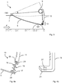
- FIG 1 is shown schematically a vehicle 100 with an aerodynamic deflector device 1 according to the invention.
- the vehicle 100 is shown in part and in side view, centered on its front part, at the level of one of the front wheels 3.
- the vehicle 100 shown in figure 1 advances from right to left, the air, considered immobile in the terrestrial frame of reference, therefore circulates from left to right in figure 1 .
- the orientation of the air flow F makes it possible to define a “downstream” and an “upstream” respectively in the direction of travel of the air flow and in the opposite direction. Terms such as “before”, “after”, “in front”, “behind” are defined using the direction and direction of travel of the car 100 as orientation.
- the transverse direction is given by the axis of rotation of the wheels 3, in a straight line.
- the aerodynamic deflector device 1 is arranged upstream of the wheel 3, under the bodywork at the front of the car 100.
- the aerodynamic device 1 is configured to switch between a retracted position and a deployed position.
- the aerodynamic deflector device 1, of which a deflector wall 5 is visible, is shown in the deployed position.
- the aerodynamic deflector device 1 is shown in more detail in figure 2 .
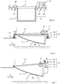
- the aerodynamic deflector device 1 shown comprises a deflector wall 5, which can be set in motion around an axis 7, a pinion 9 cooperating with a rack 11 for setting the deflector wall 5 in motion and an elastic module 13.
- the deflector wall 5 is movable in rotation about the axis 7 between a deployed position (shown in solid lines) and a retracted position (shown in dotted lines). In the deployed position, the deflector wall 5 is lowered and protrudes for the most part from the body of the vehicle 100. In the retracted position, the deflector wall 5 is raised in a housing of the body of the vehicle 100 where it is at least partially retracted. .
- the deflector device further comprises a fixed frame 39 serving as a support, illustrated in figure 9 , with the deflector wall 5 being movable in a retracted or deployed position relative to this fixed frame 39.
- the angle of rotation ⁇ has a maximum value ⁇ 0 .
- the deflector wall 5 has an aerodynamic profile in a ramp or in semi-ogive from the axis 7, up to a trailing edge located at the rear and downstream, towards the wheel 3 of the vehicle 100.
- the deflector wall 5 is made of a hard, light and impact-resistant material , for example molded plastic, in particular by injection.
- the plastic used can be supplemented with fibers, for example glass or carbon.
- the deflector wall 5 has a U-shaped section, the vertical branches of which are shortened as they approach the axis 7, and whose width at the level of the trailing edge corresponds to that of the wheel 3 to be covered.
- control unit The movement of the deflector wall 5 between the deployed and retracted positions is effected by rotating the pinion 9 by means of an actuator, in particular electric, for example by means of an electric motor, controlled by a control unit.
- control of the vehicle 100 Such a control unit generally comprises an electronic memory and calculation means, which are either dedicated or distributed in an electronic network of the vehicle 100.
- the control unit is configured to control one or more functions of the vehicle 100, in particular by means of electronic switches such as transistors.
- the deflector wall 5 In the deployed position, the deflector wall 5 is lowered, and is located outside the housing located in the body of the vehicle 100, and is in the path of the incoming air flow F, in the absence of the deflector wall 5, in the wheel arch 3 of the figure 1 .
- the air When entering the wheel arch, the air generates turbulence which increases the drag.
- the pinion 9 cooperates with the rack 11, which is translated vertically downward or upward depending on the direction of rotation of the pinion 9.
- the rack 11 is curved, in particular with a radius of curvature corresponding to the length of the deflector wall 5 , between the axis 7 and its rear end at the level of which it is connected to the rack 11.
- the rack 11 is here in particular of rectangular section, with the long sides in the longitudinal direction of the vehicle 100, and crenellations arranged on its front face.
- the lower end of the rack 11 is connected to an elastic module 13.
- the other end of the elastic module 13 is connected to the rear end (at the level of the trailing edge) of the deflector wall 5.
- the elastic module 13 is elastically deformable between two states: a state of least deformation, adopted in the absence of external actions, and a deformed state, adopted when an obstacle exerts a force, in particular a vertical force, on the deflector wall 5.
- state of least deformation is meant here a state adopted in normal operation in which the elastic energy of deformation is minimal. In particular, in the presence of mechanical stops, the state of least deformation may be different from the rest configuration of the elastic element considered.
- FIG. 3 The case of a collision with an obstacle O is represented in figure 3 .
- the obstacle O is of a height greater than the vertical interval between the ground and the lower edge of the deflector surface 5. Consequently, when the vehicle 100 rolls over said obstacle O , the obstacle O exerts a force normal to the deflector surface 5 at the point of contact. In particular, the force exerted by the obstacle O has a significant upward vertical component.
- the obstacle O can for example be a branch fallen from a tree on the roadway, a stone having rolled from a side, an object abandoned from a car further ahead in traffic.
- the obstacles O hit the deflector wall 5 at a speed close to or equal to that of the vehicle.
- the deflector wall 5 is lowered only when the speed is sufficiently high, in particular higher than the usual speeds in built-up areas (approximately 50 to 60 km / h).
- the deployment of the deflector wall 5 is done from a speed of 60 km / h, that is to say a speed greater than the legal limit speed in built-up areas (50 km / h).
- the deflector wall 5 is retracted when the vehicle speed returns to less than 40 km / h, speed slightly higher than the usual speeds for clearing fixed and signposted obstacles such as retarders.
- the difference between the deployment speed and the retraction speed makes it possible, by hysteresis, to avoid repeated and untimely actuation of the deployment mechanism of the deflector wall 5 when the speed oscillates around the deployment speed.
- An impact between an obstacle O and the deflecting wall 5 generates forces, torques and vibrations which may, in the absence of elastic modulus 13, lead to deformation or rupture of the deflecting wall 5.
- the obstacle O pushes the deflector wall 5 upwards, which brings the elastic modulus 13 to the deformed state.
- the elastic modulus 13 is compressed here, the position angle ⁇ of the deflector wall 5 is then less than ⁇ 0 , the deflector wall 5 is at least partially raised, so as to be erased and leave pass the obstacle O.
- the figure 4a shows in more detail an embodiment of elastic modulus 13 usable in the examples of figures 1, 2 and 3 .
- the elastic modulus 13 is shown in engagement with the rear portion of the deflector wall 5 and with the lower end of the rack 11.
- the elastic modulus 13 essentially comprises an elastic element 15, a lower base 17, a rod 19 and a upper base 21.
- the lower base 17 is integral with the rear portion of the deflector wall 5.
- Said lower base 17 comprises a flattened metal part, glued, screwed or riveted to the rear portion of the deflector wall 5.
- a rubber or flexible plastic sole 23 is implemented between the lower base 17 and the deflector wall 5. This sole 23 absorbs part of the low amplitude vibrations generated by the detachment of the current lines at the trailing edge. of the deflector wall 5. These vibrations can in the long term be detrimental to the possible sticking of the lower base 17 in the absence of an absorbing element.
- the rod 19 and the lower base 17 may be integral, and be produced during a single common machining step, for example by molding, turning or milling.
- the upper end of the rod 19 engages with the upper base 21 which it passes through partially vertically.
- the upper base 21 is flat, made of metal, and pierced in its center with a hole (see figure 4b ).
- a pin 25 is inserted transversely into the rod 19, at its upper end, above the upper base 21.
- the pin 25 prevents the rod 19 from coming loose from the upper base 21 by retaining a portion of the rod 19 at the top. above the upper base 21.
- the pin 25 may be a beta, split, annular or simply cylindrical type pin.
- the elastic element 15 here a helical spring in compression, surrounds the rod 19.
- the elastic modulus 13 is deformed by a stress, the rod 19 is pressed into the bore of the upper base 21, and the elastic element 13 is compressed between the lower base 17 and the upper base 19 which approach.
- the elastic element 15 is selected so that the stress required to compress the elastic modulus 13 is greater than the stress generated by the air pressure in the range of speeds expected in normal traffic (50 to 130 km / h) over the area of the deflecting wall 5, but less than the deformation or breaking stress of the deflecting wall 5.
- the deformation stress of the elastic modulus 13 is less than a predetermined fraction of the theoretical value of the minimum stresses, in particularly forces, causing irreversible deformation or rupture of the deflecting wall 5, for example 70% of this value.
- Alternative embodiments may substitute for the coil spring of the elastic element 15 with a leaf spring, an elastic band, a fluid circulation cylinder, or else a compressible or stretchable body of elastic material.
- the figure 4b illustrates a particular embodiment of the upper base 21.
- the figure 4b schematically represents the lower end of the rack 11 of the aerodynamic deflector device 1.
- the upper base 21 is here an angled end portion of the rack 11, in which a bore 27 is made, of shape and dimensions corresponding to the rod 19.
- the upper base 21 is thus obtained simply by drilling and then transversely bending the end portion. lower part of the rack 11. In this way, no separate part or additional fixing is required.
- FIG 5 schematically illustrates an alternative embodiment of elastic modulus 13 for other embodiments of the invention.
- the aerodynamic deflector device 1 is seen from behind, from the location of the wheel 3.
- the deflector wall 5 is thus seen from its trailing edge, looking in the longitudinal direction towards the axis 7.
- the axis 7 of the deflector wall 5 here surrounds a fixed shaft 29.
- the fixed shaft 29 is in particular made of metal, and connected at its ends to a frame integral with the vehicle 100.
- the aerodynamic deflector device 1 comprises an elastic return element, here a return spring 31.
- the return spring 31 is a torsionally helical spring surrounding an end portion of the fixed shaft 29. It is connected on the one hand to the frame. integral with the vehicle 100, and on the other hand to the deflector wall 5.
- the return spring 31 is configured to return the deflector wall 5 to the retracted position in the absence of other stresses by returning to a configuration of least deformation.
- the elastic module 13 which also serves to deploy the deflector wall 5.
- the elastic module 13 here comprises an actuating pinion 33 forming with the pinion 9 a gear set in motion. by actuating a motor 35, in particular by means of a control unit (not shown).
- the actuating pinion 33 is engaged with one end of the spring forming the elastic element 15.
- the elastic element 15 is here a torsional coil spring.
- the other end of the elastic element 15 is engaged with the deflector wall 5.
- the return spring 31 is then progressively deformed and exerts a return torque which increases with the rotation of the deflector wall 5.
- the presence of the elastic module 13 reduces the risk of damage to the aerodynamic deflector device 1 during collisions with an obstacle O. This makes it possible to extend the expected life of the product, and reduces the risks when traveling in a vehicle 100.
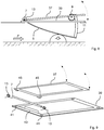
- the figure 6 shows a more general example of elastic modulus 13, adapted to various mechanisms of aerodynamic deflector devices 1.
- the deflector device 1 comprises a pinion 9 and a rack 11 similar to embodiments of figures 2 and 3 .
- the aerodynamic device embodiment 1 of the figure 6 in particular comprises a movable frame 37.
- the movable frame 37 is of the form rectangular, open in its center.
- the movable frame 37 forms a support for the elements of the aerodynamic deflector device 1.
- the axis 7 is in particular connected and articulated to the movable frame 37.
- the pinion 9 is also integral with the movable frame 37 relative to which the motor drives it. in rotation.
- Such mobile frames 37 are used as a support to obtain a modular aerodynamic deflector device 1, which can be easily assembled and transported as a whole between the various assembly workshops of the vehicle 100.
- the frame 37 is intended to cover the edge of an opening in the body or the sill of the vehicle 100, upstream of the wheel arch 3 of the vehicle 100.
- the frame 37 rests on elastic modules 13, located at each of the corners of the frame 37.
- the elastic modules 13 are here deformable by vertical translation of the frame 37, and therefore of the aerodynamic deflector device 1 attached to the frame 37.
- the elastic modules 13 are in the state of least deformation when they are compressed, which maintains the frame 37 and the aerodynamic deflector device 1 in the low position, corresponding to the deployed state of the deflector wall 5.
- Another directly derived embodiment provides for the use of extension springs, arranged under the movable frame 37.
- the elastic modules 13 each comprise a rod 19, which in this embodiment surrounds an elastic element 15, here a helical spring deformable in stretching, arranged between the movable frame 37 and a lower base 17 of the elastic modules 13.
- the rod 19 passes through a bore in the movable frame 37 and guides the movable frame 37 in vertical translation.
- the aerodynamic deflector module 1 produced according to a different mode, again comprises a movable frame 37, here movable in rotation about the axis 7 of the deflector wall 5.
- the movable frame 37 is here engaged at its front end with the axis 7, and at its rear end with at least one elastic module 13, preferably two, one at each transverse end of the rear side of the movable frame 37.
- the elastic modulus 13 visible in figure 7 comprises a curved rod 19, which guides in rotation the movable frame 37 in rotation.
- the elastic element 13 is here a helical spring deformable in compression, surrounding the rod 19, arranged between the movable frame 37 and an upper base of the elastic modulus 13.
- the lower base 17 of the elastic module 13 on which the movable frame 37 comes to rest in the absence of an obstacle O forms a stop and may comprise a disc of material absorbing vibrations, for example a rubber or soft plastic sole.
- FIG. 8 and 9 is shown another embodiment of the aerodynamic deflector module 1, which further comprises a fixed frame 39.
- the fixed frame 39 is rectangular in shape, with a rectangular opening in its center (see figure 9 ). It has holes 41 in its corners, which are used to attach by screwing or riveting the fixed frame 39 to a bottom of the vehicle 100.
- the fixed frame 39 also comprises a hinge 43 which interacts with the axis 7.
- the axis 7 is surrounded by torsionally deformable helical springs forming the elastic modules 13.
- the helical springs 13 each have two ends, respectively integral with the frame. mobile 37 and fixed frame 39.
- the axis 7 is also engaged with the movable frame 37 via hinges 45, so that the movable frame 37 is movable in rotation about the axis 7.
- the coil springs 13 are in their state of least deformation when the frame mobile 37 is arranged parallel to the fixed frame 39.
- the mobile frame 37 again carries the constituent elements of the aerodynamic deflector module 1 such as the pinion 9, the rack 11 and the deflector wall 5.
- Such aerodynamic deflector modules 1 with a fixed frame 39 and a movable frame 37 carrying the deflector wall 5 and its actuating mechanism 9, 11, can be produced with different actuating mechanisms 9, 11, for example with a longitudinal axis and a deflecting wall 5 movable in rotation about this axis.
- the invention makes it possible to obtain aerodynamic deflector modules 1, the deflector wall 5 of which is erased upon impact with an obstacle O before deformation or rupture of said deflector wall 5.
Landscapes
- Engineering & Computer Science (AREA)
- Chemical & Material Sciences (AREA)
- Combustion & Propulsion (AREA)
- Transportation (AREA)
- Mechanical Engineering (AREA)
- Physics & Mathematics (AREA)
- Fluid Mechanics (AREA)
- Body Structure For Vehicles (AREA)
Claims (5)
- Aerodynamische Ablenkvorrichtung für Kraftfahrzeug, umfassend:- eine Ablenkwand (5), die bezüglich eines festen Rahmens (39) zwischen einerseits einer eingeklappten Position, in der die Ablenkwand (5) bezüglich des festen Rahmens (39) angehoben ist, und einer ausgeklappten Position, in der die Ablenkwand (5) bezüglich des festen Rahmens (39) abgesenkt ist, beweglich montiert ist,
dadurch gekennzeichnet, dass sie ferner ein elastisches Modul (13) aufweist, das elastisch verformbar ist und dazu angeordnet ist, die Ablenkwand (5) in die ausgeklappte Position zu verschieben, wenn sich die Ablenkwand nicht mehr in der ausgeklappten Position befindet, wobei das elastische Modul (13) mit einem beweglichen Rahmen (37), der einen Mechanismus zum Ausklappen der Ablenkwand (5) trägt, kraftschlüssig verbunden ist. - Ablenkvorrichtung nach Anspruch 1, dadurch gekennzeichnet, dass das elastische Modul (13) eine Schraubenfeder oder eine Blattfeder oder einen Druckmittelzylinder oder ein elastisches Band oder auch einen komprimierbaren oder dehnbaren Körper aus elastischem Material umfasst.
- Ablenkvorrichtung nach Anspruch 1 oder 2, dadurch gekennzeichnet, dass sie eine Querachse (7) aufweist, um die die Ablenkwand (5) in Drehung versetzt wird und die ein Scharnier zwischen dem beweglichen Rahmen (37) und einem festen Rahmen (39) bildet, und dass das elastische Modul (13) um die Querachse (7) angeordnet und ist und in Eingriff einerseits mit dem beweglichen Rahmen (37) und andererseits mit dem festen Rahmen (39) steht.
- Ablenkvorrichtung nach Anspruch 1 oder 2, dadurch gekennzeichnet, dass das elastische Modul (13) eine Schraubenfeder umfasst, die torsionsverformbar ist, und dass die Torsionsfeder die Querachse (7) umgibt, und dass die Schraubenfeder zwei Enden aufweist, die mit dem festen Rahmen (39) bzw. dem beweglichen Rahmen (37) in Eingriff stehen.
- Ablenkvorrichtung nach Anspruch 1 oder 2, dadurch gekennzeichnet, dass sie mehrere elastische Module (13) aufweist, die in vertikaler Translation verformbar und an den Rändern des beweglichen Rahmens (37) angeordnet sind.
Applications Claiming Priority (2)
| Application Number | Priority Date | Filing Date | Title |
|---|---|---|---|
| FR1662345A FR3059978B1 (fr) | 2016-12-13 | 2016-12-13 | Dispositif deflecteur aerodynamique pour roue de vehicule automobile |
| PCT/FR2017/053375 WO2018109311A1 (fr) | 2016-12-13 | 2017-12-04 | Dispositif déflecteur aérodynamique pour roue de véhicule automobile |
Publications (2)
| Publication Number | Publication Date |
|---|---|
| EP3554927A1 EP3554927A1 (de) | 2019-10-23 |
| EP3554927B1 true EP3554927B1 (de) | 2021-01-06 |
Family
ID=57965979
Family Applications (1)
| Application Number | Title | Priority Date | Filing Date |
|---|---|---|---|
| EP17816981.9A Not-in-force EP3554927B1 (de) | 2016-12-13 | 2017-12-04 | Aerodynamische ablenkvorrichtung für kraftfahrzeugrad |
Country Status (5)
| Country | Link |
|---|---|
| US (1) | US10953934B2 (de) |
| EP (1) | EP3554927B1 (de) |
| CN (1) | CN110431065B (de) |
| FR (1) | FR3059978B1 (de) |
| WO (1) | WO2018109311A1 (de) |
Families Citing this family (31)
| Publication number | Priority date | Publication date | Assignee | Title |
|---|---|---|---|---|
| EP3243679B1 (de) * | 2016-05-11 | 2019-07-10 | Ningbo Geely Automobile Research & Development Co., Ltd. | Ladeluftverschluss |
| FR3059978B1 (fr) * | 2016-12-13 | 2019-04-19 | Valeo Systemes Thermiques | Dispositif deflecteur aerodynamique pour roue de vehicule automobile |
| DE102017128791B4 (de) * | 2017-12-05 | 2022-04-28 | Dr. Ing. H.C. F. Porsche Aktiengesellschaft | Frontdiffusor für ein Fahrzeug |
| DE102018119825B4 (de) | 2018-08-15 | 2023-09-21 | Dr. Ing. H.C. F. Porsche Aktiengesellschaft | Unterbodenstruktur für ein Kraftfahrzeug |
| DE102018123487A1 (de) * | 2018-09-24 | 2020-03-26 | Röchling Automotive SE & Co. KG | Aktiv verlagerbarer Radspoiler mit Überlastschutz durch Knickelement |
| KR102540890B1 (ko) * | 2018-10-29 | 2023-06-08 | 현대자동차주식회사 | 회전가림 방식 휠 가드 시스템 및 차량 |
| FR3088294B1 (fr) * | 2018-11-14 | 2022-07-08 | Valeo Systemes Thermiques | Dispositif deflecteur pour roue de vehicule automobile et vehicule comprenant un tel dispositif |
| FR3089483A1 (fr) * | 2018-12-07 | 2020-06-12 | Valeo Systemes Thermiques | Dispositif déflecteur pour roue de véhicule automobile |
| FR3089482A1 (fr) * | 2018-12-10 | 2020-06-12 | Valeo Systemes Thermiques | Dispositif déflecteur pour roue de véhicule automobile |
| DE102019210771B4 (de) | 2019-07-19 | 2022-04-28 | Magna Exteriors Gmbh | Aktive Radluftabweiseranordnung |
| FR3100219B1 (fr) * | 2019-08-26 | 2023-01-13 | Flex N Gate France | Dispositif de gestion des flux d’air et véhicule comprenant un tel dispositif |
| DE102019006675B4 (de) * | 2019-09-23 | 2022-05-19 | Mercedes-Benz Group AG | Luftleiteinrichtung im Unterbodenbereich eines Kraftwagens |
| DE102020215389B3 (de) * | 2020-09-10 | 2021-11-18 | Magna Exteriors Gmbh | Hebelgetriebe für einen Radwindabweiser sowie Verfahren zum Betrieb eines Hebelgetriebes mit Überlastschutz |
| DE102020128214A1 (de) * | 2020-10-27 | 2022-04-28 | Röchling Automotive Se & Co.Kg | Lageveränderliche Kfz-Aerodynamikbaugruppe mit verformbarer Verbindungsstruktur |
| US11679823B2 (en) | 2021-01-06 | 2023-06-20 | Honda Motor Co., Ltd. | Retractable aerodynamic side skirts for vehicles |
| US12116047B1 (en) | 2021-03-03 | 2024-10-15 | Apple Inc. | Cover panel |
| CN115892257A (zh) | 2021-09-30 | 2023-04-04 | 本田技研工业株式会社 | 车体下部结构 |
| CN115892259A (zh) | 2021-09-30 | 2023-04-04 | 本田技研工业株式会社 | 车体下部结构 |
| CN115892258A (zh) * | 2021-09-30 | 2023-04-04 | 本田技研工业株式会社 | 车体下部结构 |
| CN115892260A (zh) | 2021-09-30 | 2023-04-04 | 本田技研工业株式会社 | 车体下部结构 |
| CN116198613A (zh) * | 2021-11-30 | 2023-06-02 | 本田技研工业株式会社 | 车体下部结构 |
| JP2023095561A (ja) * | 2021-12-24 | 2023-07-06 | 株式会社東海理化電機製作所 | 整流装置 |
| CN116552658B (zh) | 2022-01-28 | 2025-09-05 | 本田技研工业株式会社 | 车体下部结构 |
| DE102022112916B4 (de) | 2022-05-23 | 2025-07-31 | Dr. Ing. H.C. F. Porsche Aktiengesellschaft | Luftleitanordnung für ein Kraftfahrzeug |
| JP7476931B2 (ja) * | 2022-09-07 | 2024-05-01 | トヨタ自動車株式会社 | ガード部材 |
| NL2033854B1 (en) * | 2022-12-27 | 2024-07-08 | Daf Trucks Nv | Vehicle comprising a bottom plate with a movable section |
| US12473036B2 (en) * | 2023-08-08 | 2025-11-18 | Toyota Motor Engineering & Manufacturing North America, Inc. | Vehicle tire guard device |
| FR3152785B1 (fr) * | 2023-09-13 | 2025-10-03 | Renault Sas | véhicule doté d’un déflecteur résistant placé devant chaque roue avant |
| US20250145228A1 (en) * | 2023-11-08 | 2025-05-08 | GM Global Technology Operations LLC | Reactive panel aerodynamic system for vehicle underbody |
| DE102023134733B3 (de) * | 2023-12-12 | 2024-12-24 | Dr. Ing. H.C. F. Porsche Aktiengesellschaft | Aufhängung zur Befestigung eines aerodynamischen Bauteils an einem Fahrzeug |
| CN119796355B (zh) * | 2025-01-03 | 2025-12-16 | 广州汽车集团股份有限公司 | 扰流板组件、车辆和车辆的控制方法 |
Family Cites Families (26)
| Publication number | Priority date | Publication date | Assignee | Title |
|---|---|---|---|---|
| US4159140A (en) * | 1978-03-24 | 1979-06-26 | Ford Motor Company | Self-deployable air spoiler assembly |
| IT1153678B (it) * | 1982-12-10 | 1987-01-14 | Alfa Romeo Spa | Spoiler a posizionamento automatico per un autoveicolo |
| JPS63110078A (ja) * | 1986-10-27 | 1988-05-14 | Tsutomu Miwa | 下垂式エヤダムスカ−ト |
| FR2791630B1 (fr) * | 1999-04-01 | 2001-06-15 | Rehau Sa | Vehicule automobile a element aerodynamique escamotable |
| CN1308178C (zh) * | 2000-12-23 | 2007-04-04 | 宝马公司 | 汽车车身外壳的平坦部分 |
| FR2845334B1 (fr) * | 2002-10-02 | 2004-11-19 | Plastic Omnium Cie | Pare-chocs de vehicule comportant un spoiler articule entre trois positions d'equilibre stable |
| FR2858793B1 (fr) * | 2003-08-13 | 2006-12-01 | Peugeot Citroen Automobiles Sa | Element aerodynamique pour la reduction de la trainee et de la portance d'un vehicule automobile |
| US7686382B2 (en) * | 2005-10-12 | 2010-03-30 | Gm Global Technology Operations, Inc. | Reversibly deployable air dam |
| US7845709B2 (en) * | 2006-10-31 | 2010-12-07 | Gm Global Technology Operations, Inc. | Active material actuated flow trips |
| FR2927303A1 (fr) * | 2008-02-08 | 2009-08-14 | Peugeot Citroen Automobiles Sa | Dispositif pour reduire la trainee et/ou la portance d'un vehicule automobile et vehicule automobile equipe d'un tel dispositif |
| DE102009034906A1 (de) * | 2009-07-28 | 2011-02-03 | GM Global Technology Operations, Inc., Detroit | Vorderteil für eine Kraftfahrzeugkarosserie |
| US8186746B2 (en) * | 2010-02-01 | 2012-05-29 | GM Global Technology Operations LLC | Passively deployable air dam for a vehicle |
| FR2959195B1 (fr) * | 2010-04-23 | 2012-06-01 | Peugeot Citroen Automobiles Sa | Vehicule automobile comportant des moyens aerodynamiques positiones en avant d'une roue et de son dispositif de freinage |
| US8727425B1 (en) * | 2010-05-27 | 2014-05-20 | Strehl, Llc | Aerodynamic trucking systems |
| KR101583920B1 (ko) * | 2014-05-02 | 2016-01-13 | 현대자동차주식회사 | 차량용 프런트 스포일러 장치 |
| EP3178730B1 (de) * | 2015-12-09 | 2019-01-30 | C.R.F. Società Consortile per Azioni | Aerodynamische vorrichtung für kraftfahrzeug |
| FR3045550B1 (fr) * | 2015-12-17 | 2019-05-17 | Valeo Systemes Thermiques | Dispositif deflecteur aerodynamique pour roue de vehicule automobile |
| FR3059978B1 (fr) * | 2016-12-13 | 2019-04-19 | Valeo Systemes Thermiques | Dispositif deflecteur aerodynamique pour roue de vehicule automobile |
| US10081400B2 (en) * | 2016-12-14 | 2018-09-25 | GM Global Technology Operations LLC | Onboard diagnostics of an active air dam assembly |
| FR3060512B1 (fr) * | 2016-12-21 | 2019-05-17 | Compagnie Plastic Omnium | Deflecteur aerodynamique retractable |
| US10370042B2 (en) * | 2017-08-02 | 2019-08-06 | GM Global Technology Operations LLC | Adjustable aerodynamic assembly and a method |
| EP3476701B1 (de) * | 2017-10-25 | 2021-01-06 | Batz, S.Coop. | Aerodynamisches system für einen radkasten eines fahrzeugs |
| JP7060783B2 (ja) * | 2017-11-20 | 2022-04-27 | 株式会社アイシン | 車両用整流装置 |
| JP7095347B2 (ja) * | 2018-03-23 | 2022-07-05 | マツダ株式会社 | 車体下面構造 |
| JP7176324B2 (ja) * | 2018-09-26 | 2022-11-22 | 株式会社アイシン | スポイラ装置 |
| US11155312B2 (en) * | 2018-11-22 | 2021-10-26 | Aisin Seiki Kabushiki Kaisha | Movable spoiler device |
-
2016
- 2016-12-13 FR FR1662345A patent/FR3059978B1/fr not_active Expired - Fee Related
-
2017
- 2017-12-04 WO PCT/FR2017/053375 patent/WO2018109311A1/fr not_active Ceased
- 2017-12-04 EP EP17816981.9A patent/EP3554927B1/de not_active Not-in-force
- 2017-12-04 CN CN201780084226.6A patent/CN110431065B/zh not_active Expired - Fee Related
- 2017-12-04 US US16/469,347 patent/US10953934B2/en not_active Expired - Fee Related
Non-Patent Citations (1)
| Title |
|---|
| None * |
Also Published As
| Publication number | Publication date |
|---|---|
| EP3554927A1 (de) | 2019-10-23 |
| CN110431065B (zh) | 2021-12-31 |
| CN110431065A (zh) | 2019-11-08 |
| FR3059978A1 (fr) | 2018-06-15 |
| WO2018109311A1 (fr) | 2018-06-21 |
| US20200010128A1 (en) | 2020-01-09 |
| FR3059978B1 (fr) | 2019-04-19 |
| US10953934B2 (en) | 2021-03-23 |
Similar Documents
| Publication | Publication Date | Title |
|---|---|---|
| EP3554927B1 (de) | Aerodynamische ablenkvorrichtung für kraftfahrzeugrad | |
| EP3416874B1 (de) | Aerodynamischer deflektor für ein kraftfahrzeugrad | |
| FR3072640A1 (fr) | Diffuseur arriere mobile de vehicule automobile a panneaux multiples | |
| EP3426544B1 (de) | Raddeflektor und entsprechendes frontendmodul | |
| FR3056185B1 (fr) | Becquet arriere d’un vehicule | |
| WO2019229200A1 (fr) | Diffuseur arriere mobile de vehicule a panneau escamotable | |
| WO2005120908A1 (fr) | Element formant support pour une partie de vehicule automobile | |
| FR2917025A1 (fr) | Ensemble d'absorption d'energie muni de deux dispositifs d'absorption | |
| WO2019063730A1 (fr) | Dispositif déflecteur de véhicule automobile | |
| FR2897038A1 (fr) | Dispositif aerodynamique pour vehicule | |
| EP3898304B1 (de) | Kraftfahrzeug mit einem motorträger und einem fahrgestell | |
| FR3066445A1 (fr) | Dispositif de regulation d'un flux d'air d'une entree d'air, pour la face avant d'un vehicule | |
| EP3060455B1 (de) | Kraftfahrzeugvorderstruktur mit einem unter dem stossfänger angeordneten beweglichen spoiler | |
| EP1645465B1 (de) | System zur Montage eines Scheinwerfers an einem Fahrzeug und Fahrzeug mit einem solchen Montagesystem | |
| EP1977934B1 (de) | Puffer zum Schutz eines Elements beim Zusammentreffen mit einem anderen Element | |
| FR2885574A1 (fr) | Pedalier de vehicule automobile apte, en cas de choc frontal sur le vehicule, a se retracter | |
| EP2782807A1 (de) | Sicherheitsvorrichtung zur verhinderung von entgleisung und zur eingleisung für eine führungseinheit mit rollen auf einer führungsschiene | |
| EP3344485B1 (de) | Vorrichtung zum abdichten eines frontlufteinlasses eines kraftfahrzeugs und frontmodul für ein kraftfahrzeug | |
| FR2995257A1 (fr) | Systeme d'attenuation de vibrations d'une vitre de vehicule, porte de vehicule et vehicule pourvu d'un tel systeme. | |
| FR3073809A1 (fr) | Diffuseur arriere mobile de vehicule a panneau translatant | |
| FR3059696A1 (fr) | Mecanisme d'entrainement d'un ouvrant de vehicule | |
| EP4051543B1 (de) | Aktives scharnier für motorhaube eines kraftfahrzeugs | |
| FR2946586A1 (fr) | Dossier de siege pour vehicule. | |
| FR3156883A1 (fr) | Dispositif de signalisation visuelle rabattable et véhicule équipé d’un tel dispositif | |
| FR3125788A1 (fr) | Véhicule automobile avec au moins une pièce de guidage en déplacement du capot en cas de choc frontal. |
Legal Events
| Date | Code | Title | Description |
|---|---|---|---|
| STAA | Information on the status of an ep patent application or granted ep patent |
Free format text: STATUS: UNKNOWN |
|
| STAA | Information on the status of an ep patent application or granted ep patent |
Free format text: STATUS: THE INTERNATIONAL PUBLICATION HAS BEEN MADE |
|
| PUAI | Public reference made under article 153(3) epc to a published international application that has entered the european phase |
Free format text: ORIGINAL CODE: 0009012 |
|
| STAA | Information on the status of an ep patent application or granted ep patent |
Free format text: STATUS: REQUEST FOR EXAMINATION WAS MADE |
|
| 17P | Request for examination filed |
Effective date: 20190522 |
|
| AK | Designated contracting states |
Kind code of ref document: A1 Designated state(s): AL AT BE BG CH CY CZ DE DK EE ES FI FR GB GR HR HU IE IS IT LI LT LU LV MC MK MT NL NO PL PT RO RS SE SI SK SM TR |
|
| AX | Request for extension of the european patent |
Extension state: BA ME |
|
| DAV | Request for validation of the european patent (deleted) | ||
| DAX | Request for extension of the european patent (deleted) | ||
| GRAP | Despatch of communication of intention to grant a patent |
Free format text: ORIGINAL CODE: EPIDOSNIGR1 |
|
| STAA | Information on the status of an ep patent application or granted ep patent |
Free format text: STATUS: GRANT OF PATENT IS INTENDED |
|
| INTG | Intention to grant announced |
Effective date: 20200806 |
|
| GRAS | Grant fee paid |
Free format text: ORIGINAL CODE: EPIDOSNIGR3 |
|
| GRAA | (expected) grant |
Free format text: ORIGINAL CODE: 0009210 |
|
| STAA | Information on the status of an ep patent application or granted ep patent |
Free format text: STATUS: THE PATENT HAS BEEN GRANTED |
|
| AK | Designated contracting states |
Kind code of ref document: B1 Designated state(s): AL AT BE BG CH CY CZ DE DK EE ES FI FR GB GR HR HU IE IS IT LI LT LU LV MC MK MT NL NO PL PT RO RS SE SI SK SM TR |
|
| REG | Reference to a national code |
Ref country code: GB Ref legal event code: FG4D Free format text: NOT ENGLISH |
|
| REG | Reference to a national code |
Ref country code: AT Ref legal event code: REF Ref document number: 1352057 Country of ref document: AT Kind code of ref document: T Effective date: 20210115 Ref country code: CH Ref legal event code: EP |
|
| REG | Reference to a national code |
Ref country code: DE Ref legal event code: R096 Ref document number: 602017031115 Country of ref document: DE |
|
| REG | Reference to a national code |
Ref country code: IE Ref legal event code: FG4D Free format text: LANGUAGE OF EP DOCUMENT: FRENCH |
|
| REG | Reference to a national code |
Ref country code: NL Ref legal event code: MP Effective date: 20210106 |
|
| REG | Reference to a national code |
Ref country code: AT Ref legal event code: MK05 Ref document number: 1352057 Country of ref document: AT Kind code of ref document: T Effective date: 20210106 |
|
| REG | Reference to a national code |
Ref country code: LT Ref legal event code: MG9D |
|
| PG25 | Lapsed in a contracting state [announced via postgrant information from national office to epo] |
Ref country code: LT Free format text: LAPSE BECAUSE OF FAILURE TO SUBMIT A TRANSLATION OF THE DESCRIPTION OR TO PAY THE FEE WITHIN THE PRESCRIBED TIME-LIMIT Effective date: 20210106 Ref country code: BG Free format text: LAPSE BECAUSE OF FAILURE TO SUBMIT A TRANSLATION OF THE DESCRIPTION OR TO PAY THE FEE WITHIN THE PRESCRIBED TIME-LIMIT Effective date: 20210406 Ref country code: PT Free format text: LAPSE BECAUSE OF FAILURE TO SUBMIT A TRANSLATION OF THE DESCRIPTION OR TO PAY THE FEE WITHIN THE PRESCRIBED TIME-LIMIT Effective date: 20210506 Ref country code: NO Free format text: LAPSE BECAUSE OF FAILURE TO SUBMIT A TRANSLATION OF THE DESCRIPTION OR TO PAY THE FEE WITHIN THE PRESCRIBED TIME-LIMIT Effective date: 20210406 Ref country code: HR Free format text: LAPSE BECAUSE OF FAILURE TO SUBMIT A TRANSLATION OF THE DESCRIPTION OR TO PAY THE FEE WITHIN THE PRESCRIBED TIME-LIMIT Effective date: 20210106 Ref country code: FI Free format text: LAPSE BECAUSE OF FAILURE TO SUBMIT A TRANSLATION OF THE DESCRIPTION OR TO PAY THE FEE WITHIN THE PRESCRIBED TIME-LIMIT Effective date: 20210106 Ref country code: GR Free format text: LAPSE BECAUSE OF FAILURE TO SUBMIT A TRANSLATION OF THE DESCRIPTION OR TO PAY THE FEE WITHIN THE PRESCRIBED TIME-LIMIT Effective date: 20210407 |
|
| PG25 | Lapsed in a contracting state [announced via postgrant information from national office to epo] |
Ref country code: SE Free format text: LAPSE BECAUSE OF FAILURE TO SUBMIT A TRANSLATION OF THE DESCRIPTION OR TO PAY THE FEE WITHIN THE PRESCRIBED TIME-LIMIT Effective date: 20210106 Ref country code: RS Free format text: LAPSE BECAUSE OF FAILURE TO SUBMIT A TRANSLATION OF THE DESCRIPTION OR TO PAY THE FEE WITHIN THE PRESCRIBED TIME-LIMIT Effective date: 20210106 Ref country code: LV Free format text: LAPSE BECAUSE OF FAILURE TO SUBMIT A TRANSLATION OF THE DESCRIPTION OR TO PAY THE FEE WITHIN THE PRESCRIBED TIME-LIMIT Effective date: 20210106 Ref country code: PL Free format text: LAPSE BECAUSE OF FAILURE TO SUBMIT A TRANSLATION OF THE DESCRIPTION OR TO PAY THE FEE WITHIN THE PRESCRIBED TIME-LIMIT Effective date: 20210106 Ref country code: AT Free format text: LAPSE BECAUSE OF FAILURE TO SUBMIT A TRANSLATION OF THE DESCRIPTION OR TO PAY THE FEE WITHIN THE PRESCRIBED TIME-LIMIT Effective date: 20210106 |
|
| PG25 | Lapsed in a contracting state [announced via postgrant information from national office to epo] |
Ref country code: IS Free format text: LAPSE BECAUSE OF FAILURE TO SUBMIT A TRANSLATION OF THE DESCRIPTION OR TO PAY THE FEE WITHIN THE PRESCRIBED TIME-LIMIT Effective date: 20210506 |
|
| REG | Reference to a national code |
Ref country code: DE Ref legal event code: R097 Ref document number: 602017031115 Country of ref document: DE |
|
| PG25 | Lapsed in a contracting state [announced via postgrant information from national office to epo] |
Ref country code: CZ Free format text: LAPSE BECAUSE OF FAILURE TO SUBMIT A TRANSLATION OF THE DESCRIPTION OR TO PAY THE FEE WITHIN THE PRESCRIBED TIME-LIMIT Effective date: 20210106 Ref country code: EE Free format text: LAPSE BECAUSE OF FAILURE TO SUBMIT A TRANSLATION OF THE DESCRIPTION OR TO PAY THE FEE WITHIN THE PRESCRIBED TIME-LIMIT Effective date: 20210106 Ref country code: SM Free format text: LAPSE BECAUSE OF FAILURE TO SUBMIT A TRANSLATION OF THE DESCRIPTION OR TO PAY THE FEE WITHIN THE PRESCRIBED TIME-LIMIT Effective date: 20210106 |
|
| PLBE | No opposition filed within time limit |
Free format text: ORIGINAL CODE: 0009261 |
|
| STAA | Information on the status of an ep patent application or granted ep patent |
Free format text: STATUS: NO OPPOSITION FILED WITHIN TIME LIMIT |
|
| PG25 | Lapsed in a contracting state [announced via postgrant information from national office to epo] |
Ref country code: SK Free format text: LAPSE BECAUSE OF FAILURE TO SUBMIT A TRANSLATION OF THE DESCRIPTION OR TO PAY THE FEE WITHIN THE PRESCRIBED TIME-LIMIT Effective date: 20210106 Ref country code: DK Free format text: LAPSE BECAUSE OF FAILURE TO SUBMIT A TRANSLATION OF THE DESCRIPTION OR TO PAY THE FEE WITHIN THE PRESCRIBED TIME-LIMIT Effective date: 20210106 Ref country code: RO Free format text: LAPSE BECAUSE OF FAILURE TO SUBMIT A TRANSLATION OF THE DESCRIPTION OR TO PAY THE FEE WITHIN THE PRESCRIBED TIME-LIMIT Effective date: 20210106 |
|
| 26N | No opposition filed |
Effective date: 20211007 |
|
| PG25 | Lapsed in a contracting state [announced via postgrant information from national office to epo] |
Ref country code: ES Free format text: LAPSE BECAUSE OF FAILURE TO SUBMIT A TRANSLATION OF THE DESCRIPTION OR TO PAY THE FEE WITHIN THE PRESCRIBED TIME-LIMIT Effective date: 20210106 Ref country code: AL Free format text: LAPSE BECAUSE OF FAILURE TO SUBMIT A TRANSLATION OF THE DESCRIPTION OR TO PAY THE FEE WITHIN THE PRESCRIBED TIME-LIMIT Effective date: 20210106 |
|
| PG25 | Lapsed in a contracting state [announced via postgrant information from national office to epo] |
Ref country code: SI Free format text: LAPSE BECAUSE OF FAILURE TO SUBMIT A TRANSLATION OF THE DESCRIPTION OR TO PAY THE FEE WITHIN THE PRESCRIBED TIME-LIMIT Effective date: 20210106 |
|
| PG25 | Lapsed in a contracting state [announced via postgrant information from national office to epo] |
Ref country code: IT Free format text: LAPSE BECAUSE OF FAILURE TO SUBMIT A TRANSLATION OF THE DESCRIPTION OR TO PAY THE FEE WITHIN THE PRESCRIBED TIME-LIMIT Effective date: 20210106 |
|
| PG25 | Lapsed in a contracting state [announced via postgrant information from national office to epo] |
Ref country code: IS Free format text: LAPSE BECAUSE OF FAILURE TO SUBMIT A TRANSLATION OF THE DESCRIPTION OR TO PAY THE FEE WITHIN THE PRESCRIBED TIME-LIMIT Effective date: 20210506 |
|
| PG25 | Lapsed in a contracting state [announced via postgrant information from national office to epo] |
Ref country code: MC Free format text: LAPSE BECAUSE OF FAILURE TO SUBMIT A TRANSLATION OF THE DESCRIPTION OR TO PAY THE FEE WITHIN THE PRESCRIBED TIME-LIMIT Effective date: 20210106 |
|
| REG | Reference to a national code |
Ref country code: CH Ref legal event code: PL |
|
| GBPC | Gb: european patent ceased through non-payment of renewal fee |
Effective date: 20211204 |
|
| REG | Reference to a national code |
Ref country code: BE Ref legal event code: MM Effective date: 20211231 |
|
| PG25 | Lapsed in a contracting state [announced via postgrant information from national office to epo] |
Ref country code: LU Free format text: LAPSE BECAUSE OF NON-PAYMENT OF DUE FEES Effective date: 20211204 Ref country code: IE Free format text: LAPSE BECAUSE OF NON-PAYMENT OF DUE FEES Effective date: 20211204 Ref country code: GB Free format text: LAPSE BECAUSE OF NON-PAYMENT OF DUE FEES Effective date: 20211204 |
|
| PG25 | Lapsed in a contracting state [announced via postgrant information from national office to epo] |
Ref country code: BE Free format text: LAPSE BECAUSE OF NON-PAYMENT OF DUE FEES Effective date: 20211231 |
|
| PG25 | Lapsed in a contracting state [announced via postgrant information from national office to epo] |
Ref country code: LI Free format text: LAPSE BECAUSE OF NON-PAYMENT OF DUE FEES Effective date: 20211231 Ref country code: CH Free format text: LAPSE BECAUSE OF NON-PAYMENT OF DUE FEES Effective date: 20211231 |
|
| PG25 | Lapsed in a contracting state [announced via postgrant information from national office to epo] |
Ref country code: NL Free format text: LAPSE BECAUSE OF NON-PAYMENT OF DUE FEES Effective date: 20210206 Ref country code: CY Free format text: LAPSE BECAUSE OF FAILURE TO SUBMIT A TRANSLATION OF THE DESCRIPTION OR TO PAY THE FEE WITHIN THE PRESCRIBED TIME-LIMIT Effective date: 20210106 |
|
| P01 | Opt-out of the competence of the unified patent court (upc) registered |
Effective date: 20230528 |
|
| PG25 | Lapsed in a contracting state [announced via postgrant information from national office to epo] |
Ref country code: HU Free format text: LAPSE BECAUSE OF FAILURE TO SUBMIT A TRANSLATION OF THE DESCRIPTION OR TO PAY THE FEE WITHIN THE PRESCRIBED TIME-LIMIT; INVALID AB INITIO Effective date: 20171204 |
|
| PGFP | Annual fee paid to national office [announced via postgrant information from national office to epo] |
Ref country code: FR Payment date: 20231220 Year of fee payment: 7 Ref country code: DE Payment date: 20231208 Year of fee payment: 7 |
|
| PG25 | Lapsed in a contracting state [announced via postgrant information from national office to epo] |
Ref country code: MK Free format text: LAPSE BECAUSE OF FAILURE TO SUBMIT A TRANSLATION OF THE DESCRIPTION OR TO PAY THE FEE WITHIN THE PRESCRIBED TIME-LIMIT Effective date: 20210106 |
|
| PG25 | Lapsed in a contracting state [announced via postgrant information from national office to epo] |
Ref country code: MT Free format text: LAPSE BECAUSE OF FAILURE TO SUBMIT A TRANSLATION OF THE DESCRIPTION OR TO PAY THE FEE WITHIN THE PRESCRIBED TIME-LIMIT Effective date: 20210106 |
|
| REG | Reference to a national code |
Ref country code: DE Ref legal event code: R119 Ref document number: 602017031115 Country of ref document: DE |
|
| PG25 | Lapsed in a contracting state [announced via postgrant information from national office to epo] |
Ref country code: DE Free format text: LAPSE BECAUSE OF NON-PAYMENT OF DUE FEES Effective date: 20250701 |
|
| PG25 | Lapsed in a contracting state [announced via postgrant information from national office to epo] |
Ref country code: FR Free format text: LAPSE BECAUSE OF NON-PAYMENT OF DUE FEES Effective date: 20241231 |
|
| PG25 | Lapsed in a contracting state [announced via postgrant information from national office to epo] |
Ref country code: TR Free format text: LAPSE BECAUSE OF FAILURE TO SUBMIT A TRANSLATION OF THE DESCRIPTION OR TO PAY THE FEE WITHIN THE PRESCRIBED TIME-LIMIT Effective date: 20210106 |