EP3554918B1 - Articulation pour la liaison articulée d'une barre d'attelage à une caisse de wagon - Google Patents
Articulation pour la liaison articulée d'une barre d'attelage à une caisse de wagon Download PDFInfo
- Publication number
- EP3554918B1 EP3554918B1 EP17811882.4A EP17811882A EP3554918B1 EP 3554918 B1 EP3554918 B1 EP 3554918B1 EP 17811882 A EP17811882 A EP 17811882A EP 3554918 B1 EP3554918 B1 EP 3554918B1
- Authority
- EP
- European Patent Office
- Prior art keywords
- plate
- face
- base plate
- coupling rod
- spring plate
- Prior art date
- Legal status (The legal status is an assumption and is not a legal conclusion. Google has not performed a legal analysis and makes no representation as to the accuracy of the status listed.)
- Active
Links
Images


Classifications
-
- B—PERFORMING OPERATIONS; TRANSPORTING
- B61—RAILWAYS
- B61G—COUPLINGS; DRAUGHT AND BUFFING APPLIANCES
- B61G9/00—Draw-gear
- B61G9/20—Details; Accessories
- B61G9/24—Linkages between draw-bar and framework
-
- B—PERFORMING OPERATIONS; TRANSPORTING
- B61—RAILWAYS
- B61G—COUPLINGS; DRAUGHT AND BUFFING APPLIANCES
- B61G7/00—Details or accessories
- B61G7/10—Mounting of the couplings on the vehicle
Definitions
- the invention relates to an articulation for the articulated connection of a coupling rod to a car body.
- Such a linkage is, for example, from EP 1 785 329 A1 famous.
- the invention relates in particular to an articulation for the articulated connection of a coupling rod to a car body, the articulation having a base plate which can be connected to a car body and in which a feed-through opening is formed, through which an end region of the coupling rod on the car body side extends.
- the linkage also has a draw/buffing device arranged on the end region of the coupling rod on the car body side, with a front spring plate attached to the coupling rod in front of the base plate in the longitudinal direction of the coupling rod and a rear spring plate attached to the coupling rod behind the base plate in the longitudinal direction of the coupling rod.
- the draw/buffing gear also has at least one front spring element made of elastic material arranged between the base plate and the front spring plate and at least one rear spring element made of elastic material arranged between the base plate and the rear spring plate, the front spring element and the at least one rear spring element in the unloaded state are each ring- or torus-shaped.
- Such a linkage for the articulated connection of a coupling rod to a car body is, for example, from EP 1 785 329 A1 known and is used in rail vehicle technology as a rule in couplings and joints for connecting car bodies or complete trains to one another by means of automatic couplings or close couplings.
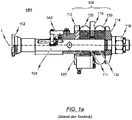
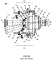
- FIG. 1a and FIG. 1b show a conventional, used in rail vehicle articulation in a side view or top view.
- the linkage is shown in a state in which no compressive or tensile forces act on the coupling rod.
- the conventional articulation 101 has a base plate 110 which can be connected to a car body (not shown) and in which a feed-through opening 111 is formed.
- the lead-through opening 111 receives the end region 103 of a coupling rod 102 on the car body side in such a way that the end region 103 of the coupling rod 102 on the car body side extends through the lead-through opening 111 .
- a drawbar/buffing device 109 which has a front spring plate 112 attached to the coupling rod 102 in front of the base plate 110 in the longitudinal direction L of the coupling rod and a rear spring plate attached to the coupling rod 102 behind the base plate 110 in the longitudinal direction L of the coupling rod 114 has.
- a spring element 120, 130 in the form of an annular rubber spring is arranged between the base plate 110 and the front spring plate 112 and between the base plate 110 and the rear spring plate 114 in such a way that the end region 103 of the coupling rod 102 on the car body side extends axially to the end region in the base plate 110 formed passage opening 111 in the spring elements 120, 130 formed openings 122, 132 extends.
- the two spring elements 120 , 130 are pushed onto the end region 103 of the coupling rod 102 on the car body side and braced with the aid of the front and rear spring plates 112 , 114 and with the aid of a locking nut 118 .
- the coupling rod 102 or the end region 103 of the coupling rod 102 on the car body side is displaced in the direction of the car body with the front spring plate 112 on the coupling rod side. so that the distance between the front spring plate 112 and the base plate 110 connected to the car body compared to the unloaded and, for example, in the Figures 1a and 1b shown state is reduced.
- the front elastomer spring element 120 arranged between the front spring plate 112 and the base plate 110 is compressed as a result of the action of the compressive forces acting on it, so that the compressive forces are transmitted in a dampened manner via the compressed front spring element 120 to the base plate 110 and the car body (not shown). .
- rear spring plate 114 is displaced relative to base plate 110 in the direction of base plate 110, so that rear spring element 130 is compressed and the tensile forces are transmitted in dampened form via the compressed rear spring element 130 to the base plate 110 and the car body, which is not shown.
- spring elements 120, 130 are in the draw / buffing gear 109 of the conventional, used in rail vehicle technology and in the Figures 1a and 1b articulation 101 illustrated as an example, hollow springs made of an elastomer material are usually used, the cross-sectional shape of these hollow springs usually having a circular shape due to the design.
- the spring elements 120, 130 assume the function of damping the tensile and impact forces occurring when power is transmitted from the coupling rod 102 to the car body.
- a further function is that in the spring elements 120, 130 part of the energy occurring during the power transmission is dissipated.
- Linkages for the articulated connection of a coupling rod to a car body must be designed to permit the horizontal and vertical pivoting movements of the coupling rod that occur during operation relative to the base plate connected to the car body, in order to be able to drive over elevations and to enable driving through depressions and cornering.
- the horizontal and vertical pivoting movements of the coupling rod relative to the base plate are absorbed by the spring elements of the draw/buffing gear. It is also desirable that the hitch rod be able to rotate to some degree relative to the base plate.
- the resetting and anti-twist device has two resetting arms 140, 140' arranged in a horizontal plane to the left and right of the car body-side end region 103 of the coupling rod 102, which are firmly connected on the one hand to the car body-side end region 103 of the coupling rod 102 and on the other hand to the base plate 110.
- Each restoring arm 140, 140' has a leg spring consisting of a helical spring 141, 141' and lever-like legs 142, 143, 142', 143'.
- the helical springs 141, 141' of the torsion springs are designed and arranged in such a way that they are subjected to torsion when the coupling rod 102 rotates about its axis.
- the end area on the car body and the opposite end area of the helical spring each merge into the lever-like legs 142, 143, 142', 143', with the legs 142, 143 on the car body being firmly connected to the base plate 110 of the linkage 101 with the aid of a screw 150.
- the opposite legs 142', 143' of the leg springs are each firmly connected via a connecting arm 144, 144' to the end region 103 of the coupling rod 102 on the car body.
- the coupling rod 102 When the coupling rod 102 is deflected horizontally or vertically relative to the base plate 110, the two coil springs 141, 141' of the torsion springs are subjected to torsion about their axis, so that the Coupling rod 102 acts a restoring force and the provision of the coupling rod 102 is made possible in the starting position.
- the coupling rod 102 pivoted in the horizontal plane relative to the base plate 110 is in FIG. 1b indicated by dotted lines.
- the construction consisting of the two torsion springs not only enables a return of a coupling rod 102 that is deflected in the horizontal and/or vertical direction relative to the base plate 110, but also serves at the same time as an anti-twist device, since the end region 103 of the coupling rod 102 on the car body side is fixed via the torsion springs is connected to the base plate 110.
- the EP 2 243 680 A1 also relates to an articulation for the articulated connection of a coupling rod to a car body, the articulation having a base plate which can be connected to the car body and has a feed-through opening through which the end area of the coupling rod on the car body side extends, and a drawbar/buffing device arranged on the end area of the coupling rod on the car body side.
- the drawbar/buffing device has a front spring plate attached to the coupling rod in front of the base plate in the longitudinal direction of the coupling rod and a rear spring plate attached to the coupling rod behind the base plate in the longitudinal direction of the coupling rod.
- a front elastomer spring element is arranged between the base plate and the front spring plate.
- a rear elastomeric spring element is positioned between the base plate and the rear spring seat.
- the front spring element and/or the rear spring element are/are in engagement with the base plate in such a way that rotational forces transmitted by the coupling rod are introduced into the base plate at right angles without slippage will.
- the invention is based on the object of further developing a linkage of the type mentioned at the outset in such a way that a centering and in particular a resetting of a twisted coupling rod during operation can be effected in a manner that is simple to implement but effective without additional components being required for this purpose.
- the linkage should be simpler in its entirety compared to the solution known from the prior art and shown above as an example.
- the object on which the invention is based is achieved according to the invention with a linkage of the type mentioned at the outset in that the rear spring plate has an end face that faces the at least one rear spring element and is contoured at least in regions, and the base plate has an end face that faces the at least one rear spring element, at least in regions having a contoured end face, the contour of the end face of the rear spring plate being at least partially complementary to the contour of the end face of the base plate.
- the term “contoured end face” used herein designates a regular surface—in the sense of differential geometry.
- regular surface or “differentiable surface” is a mathematical object from differential geometry. With the help of this term, the commonly used term of area is defined more precisely in the mathematical context. The definition of this term clearly means that pieces of a plane are deformed and stapled together in such a way that there are no corners or edges, so that a tangential plane can be created at any point in the resulting structure. In contrast to the topological surface, a derivation of a mapping can be explained on the regular surface - due to the existence of a tangential plane.
- the at least one spring element of the drawbar/buffing device arranged on the end region of the coupling rod on the car body side i.e. the front spring element and/or the at least one rear spring element, is clamped between correspondingly contoured surfaces, the annular or toroidal spring element correspondingly deformed at least in certain areas.
- the preload acting on the spring element is selected such that even in the unloaded state of the draw/buffing device arranged on the car body end region of the coupling rod, the ring-shaped or toroidal spring element is elastically deformed in the unloaded state.
- the Elastic deformation of the spring element caused by the contoured surfaces causes the spring element to engage the base plate in such a way that rotational forces transmitted by the coupling rod are introduced perpendicularly into the base plate without slipping.
- a form-fitting interlocking of at least one spring element of the drawbar/buffing gear and the base plate is achieved, so that when the coupling rod is twisted, the rotational forces transmitted by the coupling rod are transmitted via the at least one spring element, which is in form-fitting engagement with the base plate, at right angles to the base plate are initiated. Due to the normal forces in the connection points between the at least one spring element and the base plate, there are no shifting transverse forces, so that no slippage occurs.
- this anti-rotation device can only be implemented with spring elements that are annular or toroidal in the unloaded state because the corresponding spring element is clamped between suitably contoured surfaces and deformed accordingly.
- the solution according to the invention also has a whole range of other advantages compared to the articulation known from the prior art: in that the at least one front and/or rear spring element between the base plate with the end face that is contoured at least in certain areas and the associated spring plate with the at least partially contoured end face are arranged / is, the corresponding spring element is supported on the corresponding areas of the base plate, with which the spring element is positively engaged due to the selected bias.
- the base plate is provided with corresponding spring element receptacles, via which the corresponding spring elements can be accommodated at least in regions.
- the spring elements of the draw/buffing gear not only serve to dampen the tensile and impact forces transmitted by the coupling rod, but also take on the function of supporting the coupling rod on the base plate in the vertical and horizontal directions. Accordingly, in the solution according to the invention, the forces transmitted relative to the base plate during a horizontal and vertical pivoting movement of the coupling rod are also at least partially absorbed by the spring elements. After the load has been relieved, the spring elements ensure that the coupling rod returns to its original position.
- the spring elements used in the solution according to the invention also have the function of preventing rotation or restoring a twisted coupling rod.
- the coupling rod is twisted relative to the base plate, the rotational forces are introduced at right angles into the base plate due to the at least regionally positive engagement of the front and/or rear spring element and the base plate.
- the solution according to the invention thus represents a simple variant of a linkage, the basic structure of the linkage according to the invention being similar to the basic structure of a linkage known from the prior art, in which elastomer spring elements in the form of hollow rubber springs are used.
- the solution according to the invention can also be used in conventional couplings and joints for connecting car bodies or complete trains to one another by means of, for example, an automatic coupling or close coupling.
- the spring elements used in the linkage according to the invention preferably have circular cross sections and primarily assume the function of damping the tensile and impact forces transmitted by the linkage.
- the basic structure of the linkage according to the invention consists of a bolted coupling rod with spring plates, a front and rear elastomer spring element and a base plate together.
- the end faces of the base plate and of the spring plate facing at least one spring element are contoured accordingly and that the at least one spring element is clamped between the contoured end faces in such a way that it deforms correspondingly elastically in order to form a form-fitting engagement with the base plate, so that a slip-free transmission of rotational forces acting on the coupling rod to the base plate and in particular a reset of a twisted coupling rod is made possible. Since the anti-twist device is implemented with the help of at least one of the spring elements, the rotational forces are also dampened when they are transmitted to the base plate.
- one object of the linkage according to the invention is the transmission of tensile and impact forces or compressive forces as they occur during operation.
- the linkage is designed in such a way that tensile and compressive forces are introduced into the linkage via the coupling rod.
- the compressive forces are then transmitted to the base plate via the front spring plate and the adjacent spring element.
- Tensile forces are transferred to the base plate via the rear spring plate and the rear spring element.
- the base plate is firmly connected to the car body underframe, in particular screwed, so that the introduction of force into the underframe via the base plate is possible.
- the spring elements are supported at least in regions in the direction of rotation on the base plate in the solution according to the invention, an almost uniform loading of the spring elements can be achieved even with relatively high rotational forces transmitted by the coupling rod.
- the inventive arrangement of the spring elements relative to the base plate can in particular also effectively prevent premature wear of the spring elements.
- the basic idea on which the present invention is based is that the coupling rod or the elastomer spring elements are twisted by axial force/positive locking due to axial loading/deformation of the elastomer spring elements.
- the contour of the end face of the front spring plate and/or the contour of the end face of the rear spring plate is continuous and in particular has no sharp edges.
- the contour of the end face of the front spring plate and/or the contour of the end face of the rear spring plate is wavy at least in regions.
- the base plate is provided with a corresponding spring element receptacle, with both a spring plate serving as a pressure plate, which is fastened to the coupling rod, and a spring element receptacle on the base plate serving as a car body connection with a wavy Shape on the surface are fitted.
- An elastomeric spring element is positioned and preloaded between the two surfaces. A relatively high preload force makes it possible for the elastomer spring element to nestle against the two surfaces.
- the two wave surfaces are arranged in such a way that a wave crest on one side also coincides with a wave trough on the other side, so that the entire spring element is forced into a wavy shape and there is therefore no possibility of it pressing against the coupling rod or the Can twist connection to the car body. This also prevents the coupling rod from twisting against the car body connection.
- At least one of the two spring plates has at least two and preferably four wave crests pointing in the direction of the base plate, with between these wave crests there is a wave trough.
- the ones pointing towards the base plate Wave crests of the spring plate should lie on a common circular line, with the circular angle between adjacent wave crests being the same.
- the lead-through opening provided in the base plate is designed in terms of the shape of its opening cross-section in such a way that, in particular, horizontal pivoting of the end region of the coupling rod extending through the lead-through opening is possible in a definable angular range, in particular in an angular range of ⁇ 25°, thus enabling the coupling rod to be deflected around the Z-axis if the coupling rod is articulated to a car body via the linkage.
- the base plate and the lead-through opening formed therein are preferably formed in such a way that the coupling rod, when the full deflection is reached, rests flat against the correspondingly designed contour of the base plate.
- the term "X-axis” is the axis extending (horizontally) in the longitudinal direction of the coupling rod
- the term “Y-axis” is the horizontal axis at right angles thereto
- the term “Z-axis” is the axis extending vertically to the coupling rod in the longitudinal direction to understand extending axis.
- the respective spring elements rest flush against the base plate or against a spring element receptacle of the base plate, with the spring elements preferably being pretensioned between the respective spring plates and the base plate.
- the coupling rod can be supported and reset in the Y and Z directions.
- the return of the coupling rod with regard to the axis of rotation of the coupling rod is effected by the form-fitting engagement of the at least one spring element and the base plate, with--as already explained--in this way the rotational forces transmitted by the coupling rod are introduced at right angles into the base plate without slip.
- a bearing also being provided which is provided in the feed-through opening of the base plate and designed to support the end area of the coupling rod running through the feed-through opening.
- the front and/or rear spring plate has at least one cam pointing in the direction of the base plate and protruding from the end face of the corresponding spring plate.
- cam is intended to describe an area that protrudes from the contour of the end face and in particular tapers in the direction of the base plate, with the contour of the spring plate no longer describing a regular surface in the sense of differential geometry in the area of the cam.
- cams in particular arranged equidistantly, are preferably used.
- At least one cam is assigned to the base plate, which protrudes from the end face of the base plate facing the front or rear spring plate, pointing in the direction of the front or rear spring plate.
- cam-shaped areas leads to improved anti-twist protection, since the cam-shaped areas are designed to penetrate into the spring elements made of an elastic material. In other words, the cams work their way into the elastomeric elements, further preventing them from twisting.
- two spring elements made of elastic material are provided between the front spring plate and the base plate, with an intermediate plate being arranged between these two spring elements. Furthermore, it is provided that the intermediate plate has an end face facing the front spring plate and an end face facing the base plate. In this context it is conceivable if the dem front spring plate facing end face of the intermediate plate has at least partially a contour which is complementary to the contour of the front spring plate.
- the front spring plate has at least one cam, with the end face of the intermediate plate facing the front spring plate having a recess or a through hole in the axial extension of the at least one cam of the front spring plate, with a diameter that is preferably at least corresponds to the diameter of at least one cam of the front spring plate.
- the elastomeric material of the spring elements prefferably be able to penetrate into the recess or the through-hole of the intermediate plate, in particular when a corresponding cam is formed on the front spring plate. In this way, the security against torsion is further optimized.
- the intermediate plate to have at least one cam on its end face facing the front spring plate, with the front spring plate having a recess or a through hole on its end face facing the intermediate plate in an axial extension of the at least one cam of the intermediate plate, specifically with a diameter, preferably at least the diameter of the at least one cam of the intermediate plate.
- two spring elements made of elastic material are provided between the rear spring plate and the base plate, with an intermediate plate being arranged between the two spring elements, and with the intermediate plate having an end face facing the rear spring plate and a the base plate facing end face.
- the end face of the intermediate plate facing the rear spring plate has, at least in some areas, a contour that is complementary to the contour of the rear spring plate.
- the rear spring plate has at least one cam, with the cam facing the rear spring plate End face of the intermediate plate in the axial extension of the at least one cam of the rear spring plate has a recess or a through hole, with a diameter which preferably corresponds at least to the diameter of the at least one cam of the rear spring plate.
- the intermediate plate has at least one cam on its end face facing the rear spring plate, with the rear spring plate having a recess or a through hole on its end face facing the end plate in the axial extension of the at least one cam of the intermediate plate has, with a diameter which preferably corresponds at least to the diameter of the at least one cam of the intermediate plate.
- FIG. 1a shows a partially sectioned side view of a linkage 101 known from the prior art for the articulated connection of a drawbar 102 to a car body of a rail vehicle, not shown.
- FIG. 1b shows the conventional articulation 101 according to FIG FIG. 1a in a top view.
- the conventional articulation 101 has a base plate 110 which can be firmly connected to the car body of the rail vehicle and is provided with a lead-through opening 111 through which an end region 103 of the coupling rod 102 on the car body side extends.
- the body-side end portion 103 of the coupling rod 102 is connected to the coupling rod 102 in the Figures 1a and 1b is not shown in full, firmly connected. It is conceivable here that the end region 103 of the coupling rod 102 on the car body side is designed as an integral part of the coupling rod 102 . As an alternative to this, it is of course also conceivable that the end region 103 of the coupling rod 102 on the car body side is detachably connected to the coupling rod 102 .
- a drawbar/buffing device 109 is provided on the end region 103 of the coupling rod 102 on the car body side, which has a front spring plate 112 attached to the coupling rod 102 in front of the base plate 110 in the longitudinal direction L of the coupling rod and a rear spring plate 114 attached to the coupling rod 102 in the longitudinal direction L behind the base plate 110 having. Furthermore, a front elastomer spring element 120 arranged between the base plate 110 and the front spring plate 112 and a rear elastomer spring element 130 arranged between the base plate 110 and the rear spring plate 114 are provided.
- the other end of the coupling rod 102 (not shown) is connected, for example, to a coupling head (also not shown) for an automatic center buffer coupling.
- the rear spring plate 114 is fastened with the aid of a locking nut 118 at the end of the coupling rod 102 on the car body side.
- the spring elements 120, 130 used in the conventional linkage 101 are hollow rubber springs with a circular cross-section. In the drawbar/buffering device 109 of the linkage 101, they assume the function of damping the tensile and impact forces occurring during power transmission, so that the forces can be transmitted in damped form from the coupling rod 102 via the base plate 110 to the vehicle underframe (not shown).
- the illustrated embodiment of the linkage 101 known from the prior art is a so-called "donut solution" in which the elastomer spring elements 120, 130 resemble a donut, with the openings 122, 132 each have a circular cross-sectional shape.
- the end region 103 of the coupling rod 102 on the car body side extends through these openings 122, 132.
- the end region 103 of the coupling rod 102 on the car body side nevertheless runs through the feed-through opening 111 provided in the base plate 110.
- the coupling rod 102 can be pivoted on the car body, not shown, so that it can pivot horizontally and vertically
- the articulation 101 known from the prior art also has an anti-rotation device in the form of torsion springs 141, 141', which are mounted in a horizontal plane are arranged on both sides of the coupling rod 102 .
- the torsion springs 141, 141' are firmly connected to the base plate 110 via their leg regions 142, 143 pointing in the direction of the base plate 110.
- the opposite leg regions 142', 143' of the leg springs 141, 141' are each connected firmly to the coupling rod 102 via a connecting arm 144, 144'. This ensures that the coupling rod 102 cannot twist relative to the base plate 110 or is returned from a twisted position, while at the same time horizontal and vertical pivoting of the coupling rod 102 relative to the base plate 110 is made possible.
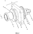
- FIG. 2 shows schematically an isometric representation of an exemplary embodiment of the articulation according to the invention.
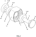
- the respective components of the linkage 1 according to FIG. 2 are based on the in FIG. 3 shown isometric exploded view in detail.
- FIG. 4 shows an isometric individual representation of a spring plate serving as a pressure plate of an exemplary embodiment of the linkage according to the invention, such as the linkage according to FIG. 2 .
- FIG. 5 shows a schematic sectional view of a spring element which rests flush on the base plate or on a spring element receptacle of the base plate.
- the exemplary embodiment of the articulation 1 according to the invention has a basic structure which essentially corresponds to the basic structure of a conventional one and, for example, previously with reference to the illustrations in FIGS Figures 1a and 1b described linkage 101 corresponds.
- a base plate 10 which can be connected, in particular screwed, to a car body of a track-guided vehicle, not shown in the drawings.
- a feed-through opening 11 runs through the base plate 10 and accommodates the end region 3 of a coupling rod 2 on the car body side.
- a draw/buffing device 9 is arranged on the end region 3 of the coupling rod 2 on the car body side.
- This drawbar/buffing device 9 has a front spring plate 12 attached to the coupling rod 2 in front of the base plate 10 in the longitudinal direction L of the coupling rod and a rear spring plate 14 attached to the coupling rod 2 behind the base plate 10 in the longitudinal direction L of the coupling rod.
- At least one--in the exemplary embodiment shown exactly two--front elastomer spring element 20 is arranged between the base plate 10 and the front spring plate 12, and at least one--exactly one in the exemplary embodiment of the articulation 1 according to the invention shown--between the base plate 10 and the rear spring plate 14 arranged rear elastomer spring element 30 is provided.
- Each spring element 20, 30 has an opening 22, 32 which is aligned axially with respect to the feed-through opening 11 formed in the base plate 10 and through which the end region 3 of the coupling rod 2 on the car body side runs.
- the two spring plates 12 , 14 can also have an opening formed axially with respect to the centrally arranged feed-through opening 11 of the base plate 10 . Accordingly, the front spring plate 12 can be slid onto the end region 3 of the coupling rod 2 on the car body side and fixed to a stop 19 which is firmly connected to the coupling rod 2 . Thereafter, the front spring element 20, the base plate 10, the rear spring element 30 and the rear spring plate 14 can be pushed onto the car body-side end region 3 of the coupling rod 2 in sequence. A locking nut 18 can then be pushed onto the body-side end of the end region 3 of the coupling rod 2, which fixes the rear spring plate 14 and at the same time prestresses the front and rear spring elements 20, 30 accordingly.
- the front spring plate 12 can also be formed integrally in the form of a flange-like projection with the end region 3 of the coupling rod 2 on the vehicle body.
- the front spring plate 12 - similar to the rear spring plate 14 - is pushed as a separate component onto the car body end region 3 of the coupling rod 2 and fixed accordingly at a suitable point.
- the end region 3 of the coupling rod 2 on the car body side rests flush against the respective spring elements 20 , 30 in the openings 22 , 32 formed in the front spring element 20 and rear spring element 30 .
- at least the end region 3 of the coupling rod 2 on the car body side has a circular cross-sectional geometry with a cross section which is at least the same size and preferably slightly larger than the diameter of the openings 22, 32 provided centrally in the spring elements 20, 30.
- the exemplary embodiment of the linkage 1 provides that the ring-shaped or toroidal front spring element 20 and/or the ring-shaped or toroidal rear spring element 30 engage with the base plate 10 stand or stands that the rotational forces transmitted by the coupling rod 2 are introduced at right angles into the base plate 10 without slipping.
- the front spring plate 12 faces the front spring element 20, at least partially contoured end face and the base plate 10 has an at least partially contoured end face facing the front spring element 20, wherein the contour of the end face of the front spring plate 12 is at least partially complementary to the contour of the end face of the base plate.
- the rear spring plate 14 faces the at least one rear spring element 30 and is contoured at least in regions
- the base plate 10 faces the at least one rear spring element 30 and is contoured at least in regions Has end face, wherein the contour of the end face of the rear spring plate 12 is at least partially complementary to the contour of the end face of the base plate.
- the corresponding end faces of the base plate 10 or the spring plates 12, 14 in particular that they have a wavy contour at least in certain areas, with the wavy shape being aligned radially with regard to the longitudinal direction L of the coupling rod such that the respective wave troughs and wave crests are aligned with respect to the longitudinal direction L of the coupling rod.
- the cross-sectional view in FIG. 5 reference is also made to the cross-sectional view in FIG. 5 referred.
- FIG. 6 a further exemplary embodiment of a spring plate serving as a pressure plate is shown in an isometric individual representation.
- the spring plate serving as a pressure plate essentially corresponds to that in FIG. 4 shown spring plate, although in accordance with the embodiment FIG. 6 a more pronounced wave contour is chosen for the contoured end face compared to that in FIG. 4 embodiment shown.
- the representation in FIG. 6 It can also be seen that the contoured end face represents a regular surface in terms of differential geometry.
- cams 40 are provided on the components on which the spring elements rest.
- An embodiment of this is in FIG. 7a shown. Accordingly, it can be seen that in this embodiment, a plurality of in the direction of the base plate (in FIG. 7a not shown) pointing and protruding from the end face of the spring plate 12, 14 cams 40 are provided. These cams 40 are preferably arranged equidistantly around the passage opening in which the end region of a coupling rod is to be accommodated.
- the cams 40 work their way into the spring elements (elastomer elements) and thus additionally prevent them from twisting.
- an intermediate plate 41 is used between two spring elements, as shown in an isometric representation, for example in FIG. 7b is shown.
- This intermediate plate 41 has through holes 42 into which the elastomeric material of the spring elements can work itself in order to prevent further twisting. It is conceivable in this context if corresponding through-holes 42 are provided, which are associated with corresponding cams of an opposite spring plate or the opposite base plate, in order to press the elastomer material displaced by the cams into the corresponding through-holes 42 .
- the elastomeric material of the spring elements is deformed into the through holes 42 .
- the burrs of the holes 42 catch in the elastomer elements and thus effectively prevent the elastomer elements from twisting in relation to one another.
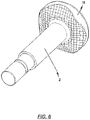
- a schematic sectional view of a linkage 1 with corresponding cams on the front spring plate 12, an intermediate plate 41 and a spring plate serving as a pressure plate with a pronounced or reinforced corrugated contour is according to the schematic sectional view FIG. 8th refer to.
- the base plate 10 is provided with a spring element receptacle, ie with a receptacle adapted to the outer contour of the spring element.
- Both a spring plate serving as a pressure plate, which is fastened to the coupling rod, and a spring element receptacle of the base plate on the car body connection are - according to the exemplary embodiment according to example FIG. 3 - Equipped with a wavy shape on the surface.
- a spring element is positioned and preloaded between the two surfaces.
- a relatively high pretensioning force makes it possible for the spring element to nestle against the two surfaces.
- the two wave surfaces are arranged so that a wave crest on one side with a wave trough on the other side collapses, so that the entire elastomer spring element is forced into a wavy shape and thus there is no possibility that it can twist against the coupling rod or the connection to the car body. This also prevents the coupling rod from twisting against the car body connection.
- an anti-twist device is provided in an easy-to-implement but nevertheless effective manner, with the need for the anti-twist device or reset of the twisted coupling rod 2 to provide supports etc. in the form of, for example, a complicated torsion spring arrangement in its starting position.
- a joint bearing can be accommodated in the feed-through opening 11 of the base plate 10 in order to mount the coupling rod 2 in the feed-through opening 11 of the base plate 10 and to enable a movement to allow the coupling rod 2 relative to the base plate 10 with the least possible material wear.
Landscapes
- Engineering & Computer Science (AREA)
- Mechanical Engineering (AREA)
- Springs (AREA)
- Closing And Opening Devices For Wings, And Checks For Wings (AREA)
Claims (15)
- Articulation (1) pour la liaison articulée d'une barre d'attelage (2) à une carrosserie, l'articulation (1) présentant les éléments suivants :- une plaque de base (10) pouvant être reliée à la carrosserie, dans laquelle la plaque est réalisée avec une ouverture de passage (11) qui est prévue pour qu'une zone d'extrémité côté carrosserie (3) de la barre d'attelage (2) s'étende à travers celle-ci ;et- un dispositif de tamponnement et de traction (9) prévu pour être agencé au niveau de la zone d'extrémité côté carrosserie (3) de la barre d'attelage (2), présentant une coupelle de ressort avant (12) située devant la plaque de base (10) dans la direction longitudinale (L) de la barre d'attelage, prévue pour être fixée à la barre d'attelage (2) et une coupelle de ressort arrière (14) située derrière la plaque de base (10) dans la direction longitudinale (L) de la barre d'attelage, prévue pour être fixée à la barre d'attelage (2),le dispositif de tamponnement et de traction (9) présentant au moins un élément ressort avant (20) en matériau élastique, agencé entre la plaque de base (10) et la coupelle de ressort avant (12), et au moins un élément ressort arrière (30) en matériau élastique, agencé entre la plaque de base (10) et la coupelle de ressort arrière (14), l'élément ressort avant (20) et ledit au moins un élément ressort arrière (30) étant réalisés, à l'état non sollicité, à chaque fois sous forme d'anneau ou de tore et en particulier avec des surfaces non profilées, la plaque de base (10) présentant une face frontale au moins partiellement profilée, orientée vers l'élément ressort avant (20) et la plaque de base (10) présentant une face frontale au moins partiellement profilée orientée vers ledit au moins un élément ressort arrière (30), le profil de la face frontale de la coupelle de ressort avant (12) et le profil de la face frontale de la coupelle de ressort arrière (14) étant continus et ne présentant en particulier pas de bords tranchants,
caractérisée en ce que la coupelle de ressort avant (12) présente une face frontale au moins partiellement profilée, orientée vers l'élément ressort avant (20), le profil de la face frontale de la coupelle de ressort avant (12) étant au moins partiellement complémentaire au profil de la face frontale de la plaque de base ; ou en ce que la coupelle de ressort arrière (14) présente une face frontale au moins partiellement profilée, orientée vers ledit au moins un élément ressort arrière (30), le profil de la face frontale de la coupelle de ressort arrière (14) étant au moins partiellement complémentaire au profil de la face frontale de la plaque de base. - Articulation (1) selon la revendication 1,la face frontale au moins partiellement profilée de la coupelle de ressort avant (12) étant une surface régulière - dans le sens de la géométrie différentielle - et/oula face frontale au moins partiellement profilée de la coupelle de ressort arrière (14) étant une surface régulière - dans le sens de la géométrie différentielle.
- Articulation (1) selon la revendication 1 ou 2,l'élément ressort avant (20) étant précontraint entre la coupelle de ressort avant (12) et la plaque de base (10) de manière telle que l'élément ressort avant (20) suit au moins partiellement le profil de la face frontale de la coupelle de ressort avant (12) et le profil de la face frontale orientée vers l'élément ressort avant (20) de la plaque de base et/ouledit au moins un élément ressort arrière (30) étant précontraint entre la coupelle de ressort arrière (14) et la plaque de base (10) de manière telle que ledit au moins un élément ressort arrière (30) suit au moins partiellement le profil de la face frontale de la coupelle de ressort arrière (14) et le profil de la face frontale de la plaque de base orientée vers ledit au moins un élément ressort arrière (30).
- Articulation (1) selon l'une quelconque des revendications 1 à 3,
le profil de la face frontale de la coupelle de ressort avant (12) et/ou le profil de la face frontale de la coupelle de ressort arrière (14) étant au moins partiellement ondulés. - Articulation (1) selon l'une quelconque des revendications 1 à 4,le profil de la face frontale de la coupelle de ressort avant (12) et/ou le profil de la face frontale de la coupelle de ressort arrière (14) variant dans la direction radiale de la coupelle de ressort correspondante,le degré de profilage augmentant de préférence dans le sens vers le bord périphérique de la coupelle de ressort correspondante.
- Articulation (1) selon l'une quelconque des revendications 1 à 5, l'ouverture de passage (11) prévue dans la plaque de base (10) étant réalisée, en ce qui concerne la mise en forme de sa section d'ouverture, de manière à permettre une oscillation horizontale de la zone d'extrémité (3) de la barre d'attelage (2) s'étendant à travers l'ouverture de passage (11) dans une zone angulaire définissable, en particulier dans une zone angulaire de ± 25° et par conséquent à permettre un déplacement de la barre d'attelage (2) autour de l'axe Z lorsque la barre d'attelage (2) est reliée de manière articulée à une carrosserie par l'intermédiaire de l'articulation (1).
- Articulation (1) selon l'une quelconque des revendications 1 à 6, ledit au moins un élément ressort avant (20) et ledit au moins un élément ressort arrière (30) présentant à chaque fois une ouverture (22, 32) orientée axialement par rapport à l'ouverture de passage (11) réalisée dans la plaque de base (10), à travers laquelle ouverture s'étend la zone d'extrémité côté carrosserie (3) de la barre d'attelage (2) et ledit au moins un élément ressort avant (20) et ledit au moins un élément ressort arrière (30) étant réalisés de manière telle qu'ils s'appuient à chaque fois dans la direction verticale et dans la direction horizontale contre les faces frontales respectives (A1, A2) de la plaque de base (10).
- Articulation (1) selon l'une quelconque des revendications 1 à 7,
au moins la zone d'extrémité côté carrosserie (3) de la barre d'attelage (2) présentant une section circulaire et un palier, en particulier un palier rotatif, étant en outre prévu, qui est agencé dans l'ouverture de passage (11) de la plaque de base (10) et réalisé pour recevoir la zone d'extrémité (3) de la barre d'attelage (2) s'étendant à travers l'ouverture de passage (11). - Articulation (1) selon l'une quelconque des revendications 1 à 8,
la coupelle de ressort avant et/ou arrière (12, 14) présentant au moins un bossage (40) pointant dans la sens de la plaque de base (10) et s'écartant de la face frontale de la coupelle de ressort (12, 14) correspondante, une multitude de bossages (40) de préférence agencés de manière équidistante étant de préférence prévus. - Articulation (1) selon l'une quelconque des revendications 1 à 9,
au moins un bossage (40) étant associé à la plaque de base (10), lequel bossage s'écarte de la face frontale de la plaque de base (10) orientée vers la coupelle de ressort avant ou arrière (12, 14) et pointe dans le sens de la coupelle de ressort avant ou arrière (12, 14). - Articulation (1) selon l'une quelconque des revendications 1 à 10,au moins deux éléments ressort (20) en matériau élastique étant prévus entre la coupelle de ressort avant (12) et la plaque de base (10) et/ou entre la plaque de base (10) et la coupelle de ressort arrière (14),une plaque intermédiaire (41) étant de préférence prévue, qui est agencée entre lesdits au moins deux éléments ressort (20).
- Articulation (1) selon l'une quelconque des revendications 1 à 11,
au moins deux éléments ressort (20) en matériau élastique étant prévus entre la coupelle de ressort avant (12) et la plaque de base (10), une plaque intermédiaire (41) étant agencée entre les deux éléments ressort (20) et la plaque intermédiaire (41) présentant une face frontale orientée vers la coupelle de ressort avant (12) et une face frontale orientée vers la plaque de base (10), la face frontale de la plaque intermédiaire (41) orientée vers la coupelle de ressort avant (12) présentant au moins partiellement un profil qui est complémentaire au profil de la coupelle de ressort avant (12). - Articulation (1) selon la revendication 11,la coupelle de ressort avant (12) présentant au moins un bossage (40) et la face frontale de la plaque intermédiaire (41) orientée vers la coupelle de ressort avant (12) présentant un évidement ou un trou de passage (42) dans le prolongement axial dudit au moins un bossage (40) de la coupelle de ressort avant (12), lequel évidement ou trou présente un diamètre qui correspond de préférence au moins au diamètre dudit au moins un bossage (40) de la coupelle de ressort avant (12) oula plaque intermédiaire (41) présentant au moins un bossage (40) sur sa face frontale orientée vers la coupelle de ressort avant (12) et la coupelle de ressort avant (12) présentant un évidement ou un trou de passage (42) sur sa face frontale orientée vers la plaque intermédiaire (41), dans le prolongement axial dudit au moins un bossage (40) de la plaque intermédiaire (41), lequel évidement ou trou présente un diamètre qui correspond de préférence au moins au diamètre dudit au moins un bossage (40) de la plaque intermédiaire (41).
- Articulation (1) selon l'une quelconque des revendications 1 à 13,
au moins deux éléments ressort (20) en matériau élastique étant prévus entre la coupelle de ressort arrière (14) et la plaque de base (10), une plaque intermédiaire (41) étant agencée entre les deux éléments ressort (20) et la plaque intermédiaire (41) présentant une face frontale orientée vers la coupelle de ressort arrière (14) et une face frontale orientée vers la plaque de base (10), la face frontale de la plaque intermédiaire (41) orientée vers la coupelle de ressort arrière (14) présentant au moins partiellement un profil qui est complémentaire au profil de la coupelle de ressort arrière (14). - Articulation (1) selon la revendication 14,la coupelle de ressort arrière (14) présentant au moins un bossage (40) et la face frontale de la plaque intermédiaire (41) orientée vers la coupelle de ressort arrière (14) présentant un évidement ou un trou de passage (42) dans le prolongement axial dudit au moins un bossage (40) de la coupelle de ressort arrière (14), lequel évidement ou trou présente un diamètre qui correspond de préférence au moins au diamètre dudit au moins un bossage (40) de la coupelle de ressort arrière (14) oula plaque intermédiaire (41) présentant au moins un bossage (40) sur sa face frontale orientée vers la coupelle de ressort arrière (14) et la coupelle de ressort arrière (14) présentant un évidement ou un trou de passage (42) sur sa face frontale orientée vers la plaque intermédiaire (41), dans le prolongement axial dudit au moins un bossage (40) de la plaque intermédiaire (41), lequel évidement ou trou présente un diamètre qui correspond de préférence au moins au diamètre dudit au moins un bossage (40) de la plaque intermédiaire (41).
Applications Claiming Priority (2)
| Application Number | Priority Date | Filing Date | Title |
|---|---|---|---|
| DE102016124808.8A DE102016124808A1 (de) | 2016-12-19 | 2016-12-19 | Anlenkung zum gelenkigen verbinden einer kupplungsstange mit einem wagenkasten |
| PCT/EP2017/080598 WO2018114236A1 (fr) | 2016-12-19 | 2017-11-28 | Articulation pour la liaison articulée d'une barre d'attelage à une caisse de wagon |
Publications (2)
| Publication Number | Publication Date |
|---|---|
| EP3554918A1 EP3554918A1 (fr) | 2019-10-23 |
| EP3554918B1 true EP3554918B1 (fr) | 2023-01-04 |
Family
ID=60654937
Family Applications (1)
| Application Number | Title | Priority Date | Filing Date |
|---|---|---|---|
| EP17811882.4A Active EP3554918B1 (fr) | 2016-12-19 | 2017-11-28 | Articulation pour la liaison articulée d'une barre d'attelage à une caisse de wagon |
Country Status (4)
| Country | Link |
|---|---|
| EP (1) | EP3554918B1 (fr) |
| CN (1) | CN110049910B (fr) |
| DE (1) | DE102016124808A1 (fr) |
| WO (1) | WO2018114236A1 (fr) |
Families Citing this family (1)
| Publication number | Priority date | Publication date | Assignee | Title |
|---|---|---|---|---|
| DE102018114745A1 (de) * | 2018-06-20 | 2019-12-24 | Voith Patent Gmbh | Horizontale Mittenrückstellung für eine Mittelpufferkupplung |
Family Cites Families (14)
| Publication number | Priority date | Publication date | Assignee | Title |
|---|---|---|---|---|
| CN2135683Y (zh) * | 1992-04-21 | 1993-06-09 | 丹东市橡胶二厂 | 橡胶空气弹簧 |
| US5351844A (en) * | 1993-06-01 | 1994-10-04 | Miner Enterprises, Inc. | Elastomeric spring unit |
| EP1785329B1 (fr) * | 2005-11-15 | 2008-04-02 | Voith Turbo Scharfenberg GmbH & Co. KG | Structure de joint |
| EP1785330A1 (fr) * | 2005-11-15 | 2007-05-16 | Voith Turbo Scharfenberg GmbH & Co. KG | Articulation d'un attelage avec une structure de joint |
| US7624884B2 (en) * | 2007-05-23 | 2009-12-01 | Miner Enterprises, Inc. | Railroad car draft gear |
| DE102008030284B4 (de) * | 2008-06-30 | 2011-04-07 | Siemens Aktiengesellschaft | Hochleistungs- Schwingplattenrichtgelenk |
| ATE522421T1 (de) * | 2009-04-23 | 2011-09-15 | Voith Patent Gmbh | Anlenkung zum gelenkigen verbinden einer kupplungsstange mit einem wagenkasten |
| CN202326873U (zh) * | 2011-11-28 | 2012-07-11 | 烟台北方星空自控科技有限公司 | 摩擦片式旋转阻尼器 |
| CN103161868A (zh) * | 2011-12-12 | 2013-06-19 | 湖北三环离合器有限公司 | 可变可控阻尼的阻尼垫片 |
| CN202703734U (zh) * | 2012-04-20 | 2013-01-30 | 株洲时代新材料科技股份有限公司 | 履带用橡胶弹性体 |
| JP5823447B2 (ja) * | 2013-06-20 | 2015-11-25 | 株式会社日本製鋼所 | ダブル形緩衝器 |
| CN203651048U (zh) * | 2013-06-20 | 2014-06-18 | 四川内江鸿强机床有限公司 | 压力机双转键式刚性离合器 |
| ES2688528T3 (es) * | 2014-10-06 | 2018-11-05 | Dellner Couplers Ab | Dispositivo de conexión adecuado para conectar una barra de acoplamiento o una barra de conexión a un vagón de un vehículo de múltiples vagones |
| CN107531258A (zh) * | 2015-04-29 | 2018-01-02 | 福伊特专利有限公司 | 用于将耦联器杆的车厢侧的端部区域与车厢铰链式连接的铰接部 |
-
2016
- 2016-12-19 DE DE102016124808.8A patent/DE102016124808A1/de not_active Withdrawn
-
2017
- 2017-11-28 EP EP17811882.4A patent/EP3554918B1/fr active Active
- 2017-11-28 CN CN201780075835.5A patent/CN110049910B/zh active Active
- 2017-11-28 WO PCT/EP2017/080598 patent/WO2018114236A1/fr not_active Ceased
Also Published As
| Publication number | Publication date |
|---|---|
| CN110049910B (zh) | 2022-03-01 |
| WO2018114236A1 (fr) | 2018-06-28 |
| DE102016124808A1 (de) | 2018-06-21 |
| CN110049910A (zh) | 2019-07-23 |
| EP3554918A1 (fr) | 2019-10-23 |
Similar Documents
| Publication | Publication Date | Title |
|---|---|---|
| EP2243680B1 (fr) | Articulation destinée à la liaison articulée d'une tige d'embrayage et d'une caisse de voiture | |
| EP1916180A2 (fr) | Dispositif d'attelage entre deux éléments de véhicule articulés, par exemple d'un véhicule articulé | |
| DE2926436A1 (de) | Universalgelenk | |
| DE2701984C2 (fr) | ||
| EP3448733B1 (fr) | Ensemble support de palier | |
| DE102015108228A1 (de) | Vorrichtung zum Verbinden eines Kupplungsschafts mit einem Wagenkasten eines spurgeführten Fahrzeuges | |
| WO2015110230A1 (fr) | Attache de composant avec surface de support supportant les forces transversales | |
| DE202012100950U1 (de) | Lenksäule für ein Kraftfahrzeug | |
| DE2452657A1 (de) | Kreuzzapfengelenk | |
| DE20009859U1 (de) | Vorrichtung zur elastischen Lagerung des Kupplungsarmes einer Mittelpufferkupplung an einem Schienenfahrzeug | |
| DE2457941A1 (de) | Schwingfaehiges wellenlager | |
| EP3554918B1 (fr) | Articulation pour la liaison articulée d'une barre d'attelage à une caisse de wagon | |
| EP1946988A1 (fr) | Dispositif de liaison articulée d'une barre d'attelage sur un véhicule | |
| DE102008048388B4 (de) | Längswellenanordnung für ein Kraftfahrzeug | |
| WO2011063951A1 (fr) | Dispositif de transmission de couple | |
| EP3623251B1 (fr) | Dispositif stabilisateur pour véhicules ferroviaires, en particulier stabilisateur de roulis | |
| EP1956252B1 (fr) | Unité de déplacement longitudinal pour arbres de transmission | |
| DE102019130321A1 (de) | Radlagereinheit für ein Kraftfahrzeug sowie Verfahren zum Herstellen einer Radlagereinheit | |
| DE202006000285U1 (de) | Elastomer-Metall-Gelenklager, insbesondere als Zentralgelenklager eines Dreieckslenkers zur Verbindung eines Achskörpers mit einem Fahrzeugaufbau | |
| DE102007021059A1 (de) | Flexibles Gelenk | |
| EP3371029B1 (fr) | Liaison articulée immobile en rotation pour relier de façon articulée une barre d'accouplement à un corps de véhicule | |
| AT16770U1 (de) | Elastischer Übergang für Gleitstückadapter | |
| DE2616633C3 (de) | Gelenkkompensator | |
| DE202012007978U1 (de) | Doppelgelenk zur Verbindung zweier gegeneinander winkelverstellbarer Wellen, vorzugsweise für den Einsatz bei Lenkwellen von Fahrzeugen, insbesondere Kraftfahrzeugen | |
| DE102010046548A1 (de) | Stabilisierungsgelenk für Schienenfahrzeug |
Legal Events
| Date | Code | Title | Description |
|---|---|---|---|
| STAA | Information on the status of an ep patent application or granted ep patent |
Free format text: STATUS: UNKNOWN |
|
| STAA | Information on the status of an ep patent application or granted ep patent |
Free format text: STATUS: THE INTERNATIONAL PUBLICATION HAS BEEN MADE |
|
| PUAI | Public reference made under article 153(3) epc to a published international application that has entered the european phase |
Free format text: ORIGINAL CODE: 0009012 |
|
| STAA | Information on the status of an ep patent application or granted ep patent |
Free format text: STATUS: REQUEST FOR EXAMINATION WAS MADE |
|
| 17P | Request for examination filed |
Effective date: 20190613 |
|
| AK | Designated contracting states |
Kind code of ref document: A1 Designated state(s): AL AT BE BG CH CY CZ DE DK EE ES FI FR GB GR HR HU IE IS IT LI LT LU LV MC MK MT NL NO PL PT RO RS SE SI SK SM TR |
|
| AX | Request for extension of the european patent |
Extension state: BA ME |
|
| RAP1 | Party data changed (applicant data changed or rights of an application transferred) |
Owner name: VOITH PATENT GMBH |
|
| DAV | Request for validation of the european patent (deleted) | ||
| DAX | Request for extension of the european patent (deleted) | ||
| STAA | Information on the status of an ep patent application or granted ep patent |
Free format text: STATUS: EXAMINATION IS IN PROGRESS |
|
| 17Q | First examination report despatched |
Effective date: 20210804 |
|
| GRAP | Despatch of communication of intention to grant a patent |
Free format text: ORIGINAL CODE: EPIDOSNIGR1 |
|
| STAA | Information on the status of an ep patent application or granted ep patent |
Free format text: STATUS: GRANT OF PATENT IS INTENDED |
|
| INTG | Intention to grant announced |
Effective date: 20220727 |
|
| GRAS | Grant fee paid |
Free format text: ORIGINAL CODE: EPIDOSNIGR3 |
|
| GRAA | (expected) grant |
Free format text: ORIGINAL CODE: 0009210 |
|
| STAA | Information on the status of an ep patent application or granted ep patent |
Free format text: STATUS: THE PATENT HAS BEEN GRANTED |
|
| AK | Designated contracting states |
Kind code of ref document: B1 Designated state(s): AL AT BE BG CH CY CZ DE DK EE ES FI FR GB GR HR HU IE IS IT LI LT LU LV MC MK MT NL NO PL PT RO RS SE SI SK SM TR |
|
| REG | Reference to a national code |
Ref country code: GB Ref legal event code: FG4D Free format text: NOT ENGLISH |
|
| REG | Reference to a national code |
Ref country code: DE Ref legal event code: R096 Ref document number: 502017014305 Country of ref document: DE |
|
| REG | Reference to a national code |
Ref country code: CH Ref legal event code: EP |
|
| REG | Reference to a national code |
Ref country code: AT Ref legal event code: REF Ref document number: 1541752 Country of ref document: AT Kind code of ref document: T Effective date: 20230115 |
|
| REG | Reference to a national code |
Ref country code: IE Ref legal event code: FG4D Free format text: LANGUAGE OF EP DOCUMENT: GERMAN |
|
| REG | Reference to a national code |
Ref country code: SE Ref legal event code: TRGR |
|
| REG | Reference to a national code |
Ref country code: LT Ref legal event code: MG9D |
|
| REG | Reference to a national code |
Ref country code: NL Ref legal event code: MP Effective date: 20230104 |
|
| PG25 | Lapsed in a contracting state [announced via postgrant information from national office to epo] |
Ref country code: NL Free format text: LAPSE BECAUSE OF FAILURE TO SUBMIT A TRANSLATION OF THE DESCRIPTION OR TO PAY THE FEE WITHIN THE PRESCRIBED TIME-LIMIT Effective date: 20230104 |
|
| P01 | Opt-out of the competence of the unified patent court (upc) registered |
Effective date: 20230613 |
|
| PG25 | Lapsed in a contracting state [announced via postgrant information from national office to epo] |
Ref country code: RS Free format text: LAPSE BECAUSE OF FAILURE TO SUBMIT A TRANSLATION OF THE DESCRIPTION OR TO PAY THE FEE WITHIN THE PRESCRIBED TIME-LIMIT Effective date: 20230104 Ref country code: PT Free format text: LAPSE BECAUSE OF FAILURE TO SUBMIT A TRANSLATION OF THE DESCRIPTION OR TO PAY THE FEE WITHIN THE PRESCRIBED TIME-LIMIT Effective date: 20230504 Ref country code: NO Free format text: LAPSE BECAUSE OF FAILURE TO SUBMIT A TRANSLATION OF THE DESCRIPTION OR TO PAY THE FEE WITHIN THE PRESCRIBED TIME-LIMIT Effective date: 20230404 Ref country code: LV Free format text: LAPSE BECAUSE OF FAILURE TO SUBMIT A TRANSLATION OF THE DESCRIPTION OR TO PAY THE FEE WITHIN THE PRESCRIBED TIME-LIMIT Effective date: 20230104 Ref country code: LT Free format text: LAPSE BECAUSE OF FAILURE TO SUBMIT A TRANSLATION OF THE DESCRIPTION OR TO PAY THE FEE WITHIN THE PRESCRIBED TIME-LIMIT Effective date: 20230104 Ref country code: HR Free format text: LAPSE BECAUSE OF FAILURE TO SUBMIT A TRANSLATION OF THE DESCRIPTION OR TO PAY THE FEE WITHIN THE PRESCRIBED TIME-LIMIT Effective date: 20230104 Ref country code: ES Free format text: LAPSE BECAUSE OF FAILURE TO SUBMIT A TRANSLATION OF THE DESCRIPTION OR TO PAY THE FEE WITHIN THE PRESCRIBED TIME-LIMIT Effective date: 20230104 |
|
| PG25 | Lapsed in a contracting state [announced via postgrant information from national office to epo] |
Ref country code: PL Free format text: LAPSE BECAUSE OF FAILURE TO SUBMIT A TRANSLATION OF THE DESCRIPTION OR TO PAY THE FEE WITHIN THE PRESCRIBED TIME-LIMIT Effective date: 20230104 Ref country code: IS Free format text: LAPSE BECAUSE OF FAILURE TO SUBMIT A TRANSLATION OF THE DESCRIPTION OR TO PAY THE FEE WITHIN THE PRESCRIBED TIME-LIMIT Effective date: 20230504 Ref country code: GR Free format text: LAPSE BECAUSE OF FAILURE TO SUBMIT A TRANSLATION OF THE DESCRIPTION OR TO PAY THE FEE WITHIN THE PRESCRIBED TIME-LIMIT Effective date: 20230405 Ref country code: FI Free format text: LAPSE BECAUSE OF FAILURE TO SUBMIT A TRANSLATION OF THE DESCRIPTION OR TO PAY THE FEE WITHIN THE PRESCRIBED TIME-LIMIT Effective date: 20230104 |
|
| REG | Reference to a national code |
Ref country code: DE Ref legal event code: R097 Ref document number: 502017014305 Country of ref document: DE |
|
| PG25 | Lapsed in a contracting state [announced via postgrant information from national office to epo] |
Ref country code: SM Free format text: LAPSE BECAUSE OF FAILURE TO SUBMIT A TRANSLATION OF THE DESCRIPTION OR TO PAY THE FEE WITHIN THE PRESCRIBED TIME-LIMIT Effective date: 20230104 Ref country code: RO Free format text: LAPSE BECAUSE OF FAILURE TO SUBMIT A TRANSLATION OF THE DESCRIPTION OR TO PAY THE FEE WITHIN THE PRESCRIBED TIME-LIMIT Effective date: 20230104 Ref country code: EE Free format text: LAPSE BECAUSE OF FAILURE TO SUBMIT A TRANSLATION OF THE DESCRIPTION OR TO PAY THE FEE WITHIN THE PRESCRIBED TIME-LIMIT Effective date: 20230104 Ref country code: DK Free format text: LAPSE BECAUSE OF FAILURE TO SUBMIT A TRANSLATION OF THE DESCRIPTION OR TO PAY THE FEE WITHIN THE PRESCRIBED TIME-LIMIT Effective date: 20230104 Ref country code: CZ Free format text: LAPSE BECAUSE OF FAILURE TO SUBMIT A TRANSLATION OF THE DESCRIPTION OR TO PAY THE FEE WITHIN THE PRESCRIBED TIME-LIMIT Effective date: 20230104 |
|
| PLBE | No opposition filed within time limit |
Free format text: ORIGINAL CODE: 0009261 |
|
| STAA | Information on the status of an ep patent application or granted ep patent |
Free format text: STATUS: NO OPPOSITION FILED WITHIN TIME LIMIT |
|
| PG25 | Lapsed in a contracting state [announced via postgrant information from national office to epo] |
Ref country code: SK Free format text: LAPSE BECAUSE OF FAILURE TO SUBMIT A TRANSLATION OF THE DESCRIPTION OR TO PAY THE FEE WITHIN THE PRESCRIBED TIME-LIMIT Effective date: 20230104 |
|
| 26N | No opposition filed |
Effective date: 20231005 |
|
| PG25 | Lapsed in a contracting state [announced via postgrant information from national office to epo] |
Ref country code: SI Free format text: LAPSE BECAUSE OF FAILURE TO SUBMIT A TRANSLATION OF THE DESCRIPTION OR TO PAY THE FEE WITHIN THE PRESCRIBED TIME-LIMIT Effective date: 20230104 |
|
| PG25 | Lapsed in a contracting state [announced via postgrant information from national office to epo] |
Ref country code: IT Free format text: LAPSE BECAUSE OF FAILURE TO SUBMIT A TRANSLATION OF THE DESCRIPTION OR TO PAY THE FEE WITHIN THE PRESCRIBED TIME-LIMIT Effective date: 20230104 |
|
| REG | Reference to a national code |
Ref country code: CH Ref legal event code: PL |
|
| PG25 | Lapsed in a contracting state [announced via postgrant information from national office to epo] |
Ref country code: MC Free format text: LAPSE BECAUSE OF FAILURE TO SUBMIT A TRANSLATION OF THE DESCRIPTION OR TO PAY THE FEE WITHIN THE PRESCRIBED TIME-LIMIT Effective date: 20230104 |
|
| PG25 | Lapsed in a contracting state [announced via postgrant information from national office to epo] |
Ref country code: LU Free format text: LAPSE BECAUSE OF NON-PAYMENT OF DUE FEES Effective date: 20231128 |
|
| PG25 | Lapsed in a contracting state [announced via postgrant information from national office to epo] |
Ref country code: CH Free format text: LAPSE BECAUSE OF NON-PAYMENT OF DUE FEES Effective date: 20231130 |
|
| GBPC | Gb: european patent ceased through non-payment of renewal fee |
Effective date: 20231128 |
|
| PG25 | Lapsed in a contracting state [announced via postgrant information from national office to epo] |
Ref country code: MC Free format text: LAPSE BECAUSE OF FAILURE TO SUBMIT A TRANSLATION OF THE DESCRIPTION OR TO PAY THE FEE WITHIN THE PRESCRIBED TIME-LIMIT Effective date: 20230104 Ref country code: LU Free format text: LAPSE BECAUSE OF NON-PAYMENT OF DUE FEES Effective date: 20231128 Ref country code: CH Free format text: LAPSE BECAUSE OF NON-PAYMENT OF DUE FEES Effective date: 20231130 |
|
| REG | Reference to a national code |
Ref country code: BE Ref legal event code: MM Effective date: 20231130 |
|
| REG | Reference to a national code |
Ref country code: IE Ref legal event code: MM4A |
|
| PG25 | Lapsed in a contracting state [announced via postgrant information from national office to epo] |
Ref country code: IE Free format text: LAPSE BECAUSE OF NON-PAYMENT OF DUE FEES Effective date: 20231128 |
|
| PG25 | Lapsed in a contracting state [announced via postgrant information from national office to epo] |
Ref country code: GB Free format text: LAPSE BECAUSE OF NON-PAYMENT OF DUE FEES Effective date: 20231128 |
|
| PG25 | Lapsed in a contracting state [announced via postgrant information from national office to epo] |
Ref country code: BE Free format text: LAPSE BECAUSE OF NON-PAYMENT OF DUE FEES Effective date: 20231130 |
|
| PG25 | Lapsed in a contracting state [announced via postgrant information from national office to epo] |
Ref country code: FR Free format text: LAPSE BECAUSE OF NON-PAYMENT OF DUE FEES Effective date: 20231130 |
|
| PG25 | Lapsed in a contracting state [announced via postgrant information from national office to epo] |
Ref country code: IE Free format text: LAPSE BECAUSE OF NON-PAYMENT OF DUE FEES Effective date: 20231128 Ref country code: GB Free format text: LAPSE BECAUSE OF NON-PAYMENT OF DUE FEES Effective date: 20231128 Ref country code: FR Free format text: LAPSE BECAUSE OF NON-PAYMENT OF DUE FEES Effective date: 20231130 Ref country code: BE Free format text: LAPSE BECAUSE OF NON-PAYMENT OF DUE FEES Effective date: 20231130 |
|
| PG25 | Lapsed in a contracting state [announced via postgrant information from national office to epo] |
Ref country code: BG Free format text: LAPSE BECAUSE OF FAILURE TO SUBMIT A TRANSLATION OF THE DESCRIPTION OR TO PAY THE FEE WITHIN THE PRESCRIBED TIME-LIMIT Effective date: 20230104 |
|
| PG25 | Lapsed in a contracting state [announced via postgrant information from national office to epo] |
Ref country code: BG Free format text: LAPSE BECAUSE OF FAILURE TO SUBMIT A TRANSLATION OF THE DESCRIPTION OR TO PAY THE FEE WITHIN THE PRESCRIBED TIME-LIMIT Effective date: 20230104 |
|
| REG | Reference to a national code |
Ref country code: AT Ref legal event code: MM01 Ref document number: 1541752 Country of ref document: AT Kind code of ref document: T Effective date: 20231128 |
|
| PG25 | Lapsed in a contracting state [announced via postgrant information from national office to epo] |
Ref country code: AT Free format text: LAPSE BECAUSE OF NON-PAYMENT OF DUE FEES Effective date: 20231128 |
|
| PG25 | Lapsed in a contracting state [announced via postgrant information from national office to epo] |
Ref country code: AT Free format text: LAPSE BECAUSE OF NON-PAYMENT OF DUE FEES Effective date: 20231128 |
|
| PG25 | Lapsed in a contracting state [announced via postgrant information from national office to epo] |
Ref country code: CY Free format text: LAPSE BECAUSE OF FAILURE TO SUBMIT A TRANSLATION OF THE DESCRIPTION OR TO PAY THE FEE WITHIN THE PRESCRIBED TIME-LIMIT; INVALID AB INITIO Effective date: 20171128 |
|
| PG25 | Lapsed in a contracting state [announced via postgrant information from national office to epo] |
Ref country code: HU Free format text: LAPSE BECAUSE OF FAILURE TO SUBMIT A TRANSLATION OF THE DESCRIPTION OR TO PAY THE FEE WITHIN THE PRESCRIBED TIME-LIMIT; INVALID AB INITIO Effective date: 20171128 |
|
| PG25 | Lapsed in a contracting state [announced via postgrant information from national office to epo] |
Ref country code: TR Free format text: LAPSE BECAUSE OF FAILURE TO SUBMIT A TRANSLATION OF THE DESCRIPTION OR TO PAY THE FEE WITHIN THE PRESCRIBED TIME-LIMIT Effective date: 20230104 |
|
| PGFP | Annual fee paid to national office [announced via postgrant information from national office to epo] |
Ref country code: DE Payment date: 20251119 Year of fee payment: 9 |
|
| PGFP | Annual fee paid to national office [announced via postgrant information from national office to epo] |
Ref country code: SE Payment date: 20251119 Year of fee payment: 9 |