EP3554788B1 - Geteilter formeinsatz zur herstellung eines reliefabschnitts eines formartikels und formstapel damit - Google Patents
Geteilter formeinsatz zur herstellung eines reliefabschnitts eines formartikels und formstapel damit Download PDFInfo
- Publication number
- EP3554788B1 EP3554788B1 EP17881792.0A EP17881792A EP3554788B1 EP 3554788 B1 EP3554788 B1 EP 3554788B1 EP 17881792 A EP17881792 A EP 17881792A EP 3554788 B1 EP3554788 B1 EP 3554788B1
- Authority
- EP
- European Patent Office
- Prior art keywords
- split mold
- mold insert
- offset
- split
- cavity
- Prior art date
- Legal status (The legal status is an assumption and is not a legal conclusion. Google has not performed a legal analysis and makes no representation as to the accuracy of the status listed.)
- Active
Links
Images


Classifications
-
- B—PERFORMING OPERATIONS; TRANSPORTING
- B29—WORKING OF PLASTICS; WORKING OF SUBSTANCES IN A PLASTIC STATE IN GENERAL
- B29C—SHAPING OR JOINING OF PLASTICS; SHAPING OF MATERIAL IN A PLASTIC STATE, NOT OTHERWISE PROVIDED FOR; AFTER-TREATMENT OF THE SHAPED PRODUCTS, e.g. REPAIRING
- B29C45/00—Injection moulding, i.e. forcing the required volume of moulding material through a nozzle into a closed mould; Apparatus therefor
- B29C45/17—Component parts, details or accessories; Auxiliary operations
- B29C45/26—Moulds
-
- B—PERFORMING OPERATIONS; TRANSPORTING
- B29—WORKING OF PLASTICS; WORKING OF SUBSTANCES IN A PLASTIC STATE IN GENERAL
- B29B—PREPARATION OR PRETREATMENT OF THE MATERIAL TO BE SHAPED; MAKING GRANULES OR PREFORMS; RECOVERY OF PLASTICS OR OTHER CONSTITUENTS OF WASTE MATERIAL CONTAINING PLASTICS
- B29B11/00—Making preforms
- B29B11/06—Making preforms by moulding the material
- B29B11/08—Injection moulding
-
- B—PERFORMING OPERATIONS; TRANSPORTING
- B29—WORKING OF PLASTICS; WORKING OF SUBSTANCES IN A PLASTIC STATE IN GENERAL
- B29C—SHAPING OR JOINING OF PLASTICS; SHAPING OF MATERIAL IN A PLASTIC STATE, NOT OTHERWISE PROVIDED FOR; AFTER-TREATMENT OF THE SHAPED PRODUCTS, e.g. REPAIRING
- B29C45/00—Injection moulding, i.e. forcing the required volume of moulding material through a nozzle into a closed mould; Apparatus therefor
- B29C45/17—Component parts, details or accessories; Auxiliary operations
- B29C45/26—Moulds
- B29C45/34—Moulds having venting means
-
- B—PERFORMING OPERATIONS; TRANSPORTING
- B29—WORKING OF PLASTICS; WORKING OF SUBSTANCES IN A PLASTIC STATE IN GENERAL
- B29B—PREPARATION OR PRETREATMENT OF THE MATERIAL TO BE SHAPED; MAKING GRANULES OR PREFORMS; RECOVERY OF PLASTICS OR OTHER CONSTITUENTS OF WASTE MATERIAL CONTAINING PLASTICS
- B29B11/00—Making preforms
- B29B11/14—Making preforms characterised by structure or composition
-
- B—PERFORMING OPERATIONS; TRANSPORTING
- B29—WORKING OF PLASTICS; WORKING OF SUBSTANCES IN A PLASTIC STATE IN GENERAL
- B29C—SHAPING OR JOINING OF PLASTICS; SHAPING OF MATERIAL IN A PLASTIC STATE, NOT OTHERWISE PROVIDED FOR; AFTER-TREATMENT OF THE SHAPED PRODUCTS, e.g. REPAIRING
- B29C45/00—Injection moulding, i.e. forcing the required volume of moulding material through a nozzle into a closed mould; Apparatus therefor
- B29C45/17—Component parts, details or accessories; Auxiliary operations
- B29C45/1753—Cleaning or purging, e.g. of the injection unit
-
- B—PERFORMING OPERATIONS; TRANSPORTING
- B29—WORKING OF PLASTICS; WORKING OF SUBSTANCES IN A PLASTIC STATE IN GENERAL
- B29C—SHAPING OR JOINING OF PLASTICS; SHAPING OF MATERIAL IN A PLASTIC STATE, NOT OTHERWISE PROVIDED FOR; AFTER-TREATMENT OF THE SHAPED PRODUCTS, e.g. REPAIRING
- B29C45/00—Injection moulding, i.e. forcing the required volume of moulding material through a nozzle into a closed mould; Apparatus therefor
- B29C45/17—Component parts, details or accessories; Auxiliary operations
- B29C45/26—Moulds
- B29C45/33—Moulds having transversely, e.g. radially, movable mould parts
-
- B—PERFORMING OPERATIONS; TRANSPORTING
- B29—WORKING OF PLASTICS; WORKING OF SUBSTANCES IN A PLASTIC STATE IN GENERAL
- B29C—SHAPING OR JOINING OF PLASTICS; SHAPING OF MATERIAL IN A PLASTIC STATE, NOT OTHERWISE PROVIDED FOR; AFTER-TREATMENT OF THE SHAPED PRODUCTS, e.g. REPAIRING
- B29C49/00—Blow-moulding, i.e. blowing a preform or parison to a desired shape within a mould; Apparatus therefor
- B29C49/071—Preforms or parisons characterised by their configuration, e.g. geometry, dimensions or physical properties
-
- B—PERFORMING OPERATIONS; TRANSPORTING
- B29—WORKING OF PLASTICS; WORKING OF SUBSTANCES IN A PLASTIC STATE IN GENERAL
- B29C—SHAPING OR JOINING OF PLASTICS; SHAPING OF MATERIAL IN A PLASTIC STATE, NOT OTHERWISE PROVIDED FOR; AFTER-TREATMENT OF THE SHAPED PRODUCTS, e.g. REPAIRING
- B29C49/00—Blow-moulding, i.e. blowing a preform or parison to a desired shape within a mould; Apparatus therefor
- B29C49/02—Combined blow-moulding and manufacture of the preform or the parison
- B29C2049/023—Combined blow-moulding and manufacture of the preform or the parison using inherent heat of the preform, i.e. 1 step blow moulding
-
- B—PERFORMING OPERATIONS; TRANSPORTING
- B29—WORKING OF PLASTICS; WORKING OF SUBSTANCES IN A PLASTIC STATE IN GENERAL
- B29C—SHAPING OR JOINING OF PLASTICS; SHAPING OF MATERIAL IN A PLASTIC STATE, NOT OTHERWISE PROVIDED FOR; AFTER-TREATMENT OF THE SHAPED PRODUCTS, e.g. REPAIRING
- B29C2949/00—Indexing scheme relating to blow-moulding
- B29C2949/07—Preforms or parisons characterised by their configuration
- B29C2949/0715—Preforms or parisons characterised by their configuration the preform having one end closed
-
- B—PERFORMING OPERATIONS; TRANSPORTING
- B29—WORKING OF PLASTICS; WORKING OF SUBSTANCES IN A PLASTIC STATE IN GENERAL
- B29C—SHAPING OR JOINING OF PLASTICS; SHAPING OF MATERIAL IN A PLASTIC STATE, NOT OTHERWISE PROVIDED FOR; AFTER-TREATMENT OF THE SHAPED PRODUCTS, e.g. REPAIRING
- B29C2949/00—Indexing scheme relating to blow-moulding
- B29C2949/07—Preforms or parisons characterised by their configuration
- B29C2949/073—Preforms or parisons characterised by their configuration having variable diameter
- B29C2949/0732—Preforms or parisons characterised by their configuration having variable diameter at flange portion
-
- B—PERFORMING OPERATIONS; TRANSPORTING
- B29—WORKING OF PLASTICS; WORKING OF SUBSTANCES IN A PLASTIC STATE IN GENERAL
- B29C—SHAPING OR JOINING OF PLASTICS; SHAPING OF MATERIAL IN A PLASTIC STATE, NOT OTHERWISE PROVIDED FOR; AFTER-TREATMENT OF THE SHAPED PRODUCTS, e.g. REPAIRING
- B29C2949/00—Indexing scheme relating to blow-moulding
- B29C2949/07—Preforms or parisons characterised by their configuration
- B29C2949/074—Preforms or parisons characterised by their configuration having ribs or protrusions
- B29C2949/0744—Preforms or parisons characterised by their configuration having ribs or protrusions at neck portion
-
- B—PERFORMING OPERATIONS; TRANSPORTING
- B29—WORKING OF PLASTICS; WORKING OF SUBSTANCES IN A PLASTIC STATE IN GENERAL
- B29C—SHAPING OR JOINING OF PLASTICS; SHAPING OF MATERIAL IN A PLASTIC STATE, NOT OTHERWISE PROVIDED FOR; AFTER-TREATMENT OF THE SHAPED PRODUCTS, e.g. REPAIRING
- B29C2949/00—Indexing scheme relating to blow-moulding
- B29C2949/07—Preforms or parisons characterised by their configuration
- B29C2949/074—Preforms or parisons characterised by their configuration having ribs or protrusions
- B29C2949/0745—Preforms or parisons characterised by their configuration having ribs or protrusions at flange portion
-
- B—PERFORMING OPERATIONS; TRANSPORTING
- B29—WORKING OF PLASTICS; WORKING OF SUBSTANCES IN A PLASTIC STATE IN GENERAL
- B29C—SHAPING OR JOINING OF PLASTICS; SHAPING OF MATERIAL IN A PLASTIC STATE, NOT OTHERWISE PROVIDED FOR; AFTER-TREATMENT OF THE SHAPED PRODUCTS, e.g. REPAIRING
- B29C2949/00—Indexing scheme relating to blow-moulding
- B29C2949/07—Preforms or parisons characterised by their configuration
- B29C2949/076—Preforms or parisons characterised by their configuration characterised by the shape
- B29C2949/0768—Preforms or parisons characterised by their configuration characterised by the shape characterised by the shape of specific parts of preform
- B29C2949/0769—Preforms or parisons characterised by their configuration characterised by the shape characterised by the shape of specific parts of preform characterised by the lip, i.e. very top of preform neck
-
- B—PERFORMING OPERATIONS; TRANSPORTING
- B29—WORKING OF PLASTICS; WORKING OF SUBSTANCES IN A PLASTIC STATE IN GENERAL
- B29C—SHAPING OR JOINING OF PLASTICS; SHAPING OF MATERIAL IN A PLASTIC STATE, NOT OTHERWISE PROVIDED FOR; AFTER-TREATMENT OF THE SHAPED PRODUCTS, e.g. REPAIRING
- B29C2949/00—Indexing scheme relating to blow-moulding
- B29C2949/07—Preforms or parisons characterised by their configuration
- B29C2949/076—Preforms or parisons characterised by their configuration characterised by the shape
- B29C2949/0768—Preforms or parisons characterised by their configuration characterised by the shape characterised by the shape of specific parts of preform
- B29C2949/077—Preforms or parisons characterised by their configuration characterised by the shape characterised by the shape of specific parts of preform characterised by the neck
- B29C2949/0772—Closure retaining means
- B29C2949/0773—Threads
- B29C2949/0774—Interrupted threads
-
- B—PERFORMING OPERATIONS; TRANSPORTING
- B29—WORKING OF PLASTICS; WORKING OF SUBSTANCES IN A PLASTIC STATE IN GENERAL
- B29C—SHAPING OR JOINING OF PLASTICS; SHAPING OF MATERIAL IN A PLASTIC STATE, NOT OTHERWISE PROVIDED FOR; AFTER-TREATMENT OF THE SHAPED PRODUCTS, e.g. REPAIRING
- B29C2949/00—Indexing scheme relating to blow-moulding
- B29C2949/07—Preforms or parisons characterised by their configuration
- B29C2949/076—Preforms or parisons characterised by their configuration characterised by the shape
- B29C2949/0768—Preforms or parisons characterised by their configuration characterised by the shape characterised by the shape of specific parts of preform
- B29C2949/078—Preforms or parisons characterised by their configuration characterised by the shape characterised by the shape of specific parts of preform characterised by the bottom
-
- B—PERFORMING OPERATIONS; TRANSPORTING
- B29—WORKING OF PLASTICS; WORKING OF SUBSTANCES IN A PLASTIC STATE IN GENERAL
- B29C—SHAPING OR JOINING OF PLASTICS; SHAPING OF MATERIAL IN A PLASTIC STATE, NOT OTHERWISE PROVIDED FOR; AFTER-TREATMENT OF THE SHAPED PRODUCTS, e.g. REPAIRING
- B29C49/00—Blow-moulding, i.e. blowing a preform or parison to a desired shape within a mould; Apparatus therefor
- B29C49/02—Combined blow-moulding and manufacture of the preform or the parison
- B29C49/06—Injection blow-moulding
-
- B—PERFORMING OPERATIONS; TRANSPORTING
- B29—WORKING OF PLASTICS; WORKING OF SUBSTANCES IN A PLASTIC STATE IN GENERAL
- B29K—INDEXING SCHEME ASSOCIATED WITH SUBCLASSES B29B, B29C OR B29D, RELATING TO MOULDING MATERIALS OR TO MATERIALS FOR MOULDS, REINFORCEMENTS, FILLERS OR PREFORMED PARTS, e.g. INSERTS
- B29K2105/00—Condition, form or state of moulded material or of the material to be shaped
- B29K2105/25—Solid
- B29K2105/253—Preform
- B29K2105/258—Tubular
-
- B—PERFORMING OPERATIONS; TRANSPORTING
- B29—WORKING OF PLASTICS; WORKING OF SUBSTANCES IN A PLASTIC STATE IN GENERAL
- B29L—INDEXING SCHEME ASSOCIATED WITH SUBCLASS B29C, RELATING TO PARTICULAR ARTICLES
- B29L2031/00—Other particular articles
- B29L2031/712—Containers; Packaging elements or accessories, Packages
- B29L2031/7158—Bottles
Definitions
- the present disclosure relates to injection molding, and in particular to a split mold insert for forming a relief portion of a molded article and a mold stack incorporating same.
- a molding system such as an injection molding system, forms molded articles from a molding material.
- the molding material may be a plastic or resin material, such as Polyethylene Terephthalate (PET) for example.
- PET Polyethylene Terephthalate
- the molded article may be a container, or a container precursor such as a preform capable of being subsequently blown into a beverage container (e.g. a plastic bottle).
- An injection molding system may heat the molding material to a homogeneous molten state, in which state the molding material may be referred to as "melt.”
- the melt may be injected, under pressure, into a molding cavity that is defined by a collection of components referred to as a "mold stack.”
- the mold stack typically includes, among other components, a female cavity piece and a male core piece attached to a cavity plate and a core plate respectively.
- the molding cavity that is defined by the mold stack may have a shape that substantially corresponds to a final cold-state shape of the article to be molded.
- a clamp force is applied to the cavity and core plates that is sufficient to keep the cavity and the core pieces together despite the opposing force of the pressurized melt within the molding cavity.
- a molded article such as a preform may have a neck portion (or "neck finish") having various features in relief.
- the neck portion features may include one or more of: threads for accepting and retaining a closure assembly (e.g. a bottle cap); an anti-pilferage assembly configured to cooperate with the closure assembly to indicate whether the end product (e.g. a beverage container filled with a beverage) has been tampered with; and a support ledge that cooperates with parts of the molding system.
- the relief of these features is such that removal of the neck portion from a molding cavity defined by a unitary female cavity piece would be difficult or impossible.
- the neck portion is typically defined by a split mold insert (also referred to as a neck ring) designed to separate laterally into two or more parts/halves to release the neck portion of the cooled molded article for axial ejection from the core piece.
- a split mold insert also referred to as a neck ring
- a molding cavity is empty, i.e. filled with air.
- the air is typically vented from the molding cavity through vents that are defined between mold stack components at or near the end of the melt flow path within the molding cavity. Vents may be sized to permit passage of a gas (normally air) therethrough without permitting passage of melt therethrough.
- the vent sizes may be set based on the type and/or viscosity of the melt to be used. For example, in the case where the molding material is PET, the vents may comprise gaps approximately 30 to 40 microns wide. The venting may promote molded article quality by reducing or eliminating a risk of trapped air within the molding cavity, which might otherwise cause imperfections in the molded article.
- WO 2016/149800A1 and WO 2013/016816A1 both disclose split mold inserts having offsets in their split lines.
- a split mold insert for defining a relief portion of a molded article, comprising: a body defining a mold cavity for the relief portion of the molded article, the body having a male projecting portion with a shutoff face, the shutoff face for selectively defining, in a molding configuration of the split mold insert, a parting line with an adjacent mold stack component and, in a cleaning configuration of the split mold insert, a molding surface, the male projecting portion having an outer surface configured to cooperate with a female receptacle associated with the adjacent mold stack component to provide a melt barrier in the cleaning configuration of the split mold insert, the body being split into a plurality of split mold insert parts that are separable for ejection of the molded article, each split mold insert part having a mating face for mating with a complementary mating face of an adjacent one of the split mold insert parts, the mating face having an inner face region adjacent to the mold cavity, an offset, and an outer face region on an opposite side of the offset from the
- the inner and outer face regions occupy different planes.
- the offset may be orthogonal to each of the planes occupied by the inner face region and the outer face region respectively.
- the second portion of the offset of each split mold insert part may be substantially orthogonal to the first portion of the offset.
- the offset of each split mold insert part may be substantially L-shaped.
- the second portion of the offset of each split mold insert part may be at least partially curved.
- the offset or each split mold insert part may be substantially J-shaped.
- the offsets of the complementary mating faces overlap with one another and define a gap therebetween, the gap being substantially constant regardless of whether the split mold insert is in the cleaning configuration or in a molding configuration, the gap defining a vent permitting passage of gas, but preventing passage of melt, therethrough.
- the male projecting portion of the split mold insert is tapered.
- the outer surface of the male projecting portion may be frustoconical, and the offset may terminate at the frustoconical outer surface.
- the shutoff face of the male projecting portion is annular and has a rounded peripheral edge
- the male projecting portion has a flared base
- the offset terminates in an outer surface of the male projecting portion between the rounded peripheral edge of the shutoff face and the flared base of the male projecting portion.
- the plurality of split mold insert parts is a pair of split mold insert halves.
- a mold stack for molding a molded article having relief portion comprising: a split mold insert as described above; and an adjacent mold stack component having an associated a female receptacle, the split mold insert having a cleaning configuration wherein: the shutoff face of the male projecting portion acts as a molding surface; the male projecting portion cooperates with the female receptacle to define a melt barrier, the complementary inner face regions of the split mold insert parts are spaced apart to form an extension of the mold cavity, the mold cavity extension terminating, at least in part, at the shutoff face of the split mold insert that acts as the molding surface; and the complementary offsets cooperate to prevent melt from passing therebetween and to guide melt towards the melt barrier.
- the adjacent mold stack component is a cavity insert and the female receptacle is defined in a cavity flange associated with the cavity insert.
- the inner and outer face regions of the mating face of each split mold insert part occupy different planes.
- each mating face may be orthogonal to each of the planes occupied by the inner face region and the outer face region, respectively, of the mating face.
- the second portion of the offset of each split mold insert part may be substantially orthogonal to the first portion of the offset.
- the second portion of the offset of each split mold insert part may be at least partially curved.
- the offset of each split mold insert part may be substantially J-shaped.
- the offsets of the respective complementary mating faces overlap with one another and define a gap therebetween, the gap being substantially constant regardless of whether the split mold insert is in the cleaning configuration or in a molding configuration, the gap defining a vent permitting passage of gas, but preventing passage of melt, therethrough.
- the outer surface of the male projecting portion is frustoconical and the offset terminates at the frustoconical outer surface.
- the shutoff face of the male projecting portion of the split mold insert is annular and has a rounded peripheral edge, wherein the male projecting portion has a flared base, and wherein the offset terminates in an outer surface of the male projecting portion between the rounded peripheral edge of the shutoff face and the flared base of the male projecting portion.
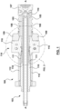
- FIG. 1 there is depicted a longitudinal cross-section of a single mold stack 103.
- the example mold stack 103 produces a molded article, which in this example is a preform 101 illustrated in FIG. 2 .
- the mold stack 103 may be one of many similar mold stacks (not illustrated) within a mold 100 that may collectively mold numerous preforms in a single batch during a single injection molding cycle.
- the mold 100 may include other components, which have been omitted from FIG. 1 for the sake of brevity.
- the mold stack 103 of FIG. 1 is in a production or molding configuration, i.e. in a configuration suitable for receiving melt into the molding cavity 105 and forming the preform 101 shown in FIG. 2 .
- the mold stack 103 also has other configurations, including a vent-cleaning configuration (also referred to as a "residue-cleaning configuration” or simply as a “cleaning configuration”), that will be described below.
- a vent-cleaning configuration also referred to as a "residue-cleaning configuration” or simply as a “cleaning configuration”
- the mold stack 103 includes a cavity insert 106 (a form of cavity piece), a gate insert 107, and a cavity flange 109.
- the cavity flange 109 is considered to be associated with the cavity insert 106, and serves to retain the cavity insert 106, and gate insert 107, within a bore in a cavity plate (not depicted).
- the cavity insert 106 and cavity flange 109 could be a unitary component.
- the cavity insert 106 defines an exterior shape of a body 113 ( FIG. 2 ) of the preform 101 to be molded, which in this case is substantially cylindrical.
- the gate insert 107 defines an exterior shape of a closed end 115 ( FIG. 2 ) of the preform 101 to be molded, which in this case is substantially conical.
- the gate insert 107 also defines a gate (aperture) through which melted molded material is injected into the molding cavity 105.
- the components 106 and 107 may be referred to as "inserts" because they are designed as modular components for insertion into a bore in a cavity plate (not depicted), to facilitate mold manufacturing and servicing.
- the cavity piece 106 and gate insert 107 could be integral with a cavity plate for example.
- the mold stack 103 further includes a core insert 110 (a form of core piece) that defines an interior surface of the preform 101 to be molded, a core ring 111 configured to define a portion of the top sealing surface 121 of the preform 101 ( FIG. 2 ), and a lock ring 112.
- the core ring 111 and lock ring 112 are configured to retain the core insert 110 with a core plate (not depicted).
- the mold stack 103 further includes a split mold insert 114 for defining the neck finish 119 of the preform 101 ( FIG. 2 ).
- the split mold insert 114 of the present embodiment comprises a pair of complementary split mold insert halves 116, 118 which are laterally (vertically in FIG. 1 ) separable, e.g. for preform ejection.
- the mold stack 103 has an operational axis A ( FIG. 1 ).
- the operational axis A may be considered as an axis along which major components of the mold 100 are moved during operation of the mold through an injection molding cycle.
- the core insert 110, core ring 111, lock ring 112 and split mold insert 114 may be movable as a unit along operational axis A away from cavity insert 106, gate insert 107, and cavity flange 109, e.g. when opening the mold for ejecting the preform 101 or closing the mold in preparation for a subsequent injection molding cycle.
- the split mold insert 114 may be movable along operational axis A relative to the core 110, while supporting the neck finish 119 of a freshly molded preform 101, to facilitate stripping of the preform 101 from the core insert 110 during normal molding operation.
- the mold stack 103 depicted in FIG. 1 may be referred to as a core lock type of mold stack.
- the term "core lock” reflects a design whereby the split mold insert halves 116, 118 are “locked” together laterally (vertically in FIG. 1 ) by virtue of being snugly seated within a female receptacles defined on adjacent mold stack components, which in this case is a cavity flange 109 and the lock ring 112, as clamping pressure is applied to the mold stack 103 in the axial direction. This relationship is illustrated in greater detail in FIG. 3 .
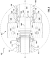
- FIG. 3 a close-up cross-sectional elevation view of a portion of mold stack 103 is depicted.
- FIG. 3 illustrates the interaction between the core ring 111, split mold insert 114, cavity flange 109 and cavity insert 106 when the example core lock type mold stack 103 is in the molding configuration.
- the core insert 110 is omitted from FIG. 3 , so that split line 143 between the split mold insert halves 116, 118 is visible.
- the cavity flange 109 defines a tapered female receptacle 130 having a generally frustoconical shape.
- the adjacent split mold insert 114 has a tapered male projecting portion 132 with a complementary shape (i.e. generally frusto-conical) that allows the tapered male projecting portion 132 to be snugly received within the tapered female receptacle 130 when the split mold insert 114 and the cavity insert 106 are in the mated molding configuration of FIG. 3 .
- the male projecting portion 132 has a shutoff face 142, which is annular in the present embodiment.
- the cavity insert 106 which is also adjacent to split mold insert 114 in the present embodiment, has a complementary shutoff face 133. As will be described, these shutoff faces will become molding surfaces when the mold stack 103 is placed into a cleaning configuration.
- the split mold insert 114 is shown in perspective view and plan view, respectively, in isolation from other mold stack components. In each of FIGS. 4 and 5 , the split mold insert 114 is shown in a molding configuration in which its halves 116, 118 are mated.
- the split line 143 that splits split mold insert 114 into two halves 116 and 118 has, relative to the central mold cavity 105, a proximal portion 141, an offset portion 145, and a distal portion 147.
- the proximal and distal portions 141 and 147 of split line 143 are each orthogonal to the axis L of lateral separation of the two halves 116, 118, whereas the offset portion 145 is parallel to the axis L.
- the offset portion 145 terminates at the tapered outer surface 139 of the male projecting portion 132 (see FIG. 4 ).
- the offset portion 145 terminates at the frustoconical face 139 of the male projecting portion 132.
- the offset portion 145 is one of the mechanisms used to prevent uncontrolled flashing from between the split mold insert halves 116, 118 when slightly separated in a cleaning configuration, as will be described.
- the split mold insert 114 also has a tapered male portion 164, on an opposite side from male projecting portion 132, for mating with a complementary female seat defined in lock ring 112 ( FIG. 4 ; see also FIG. 3 ).
- the central portion of split mold insert 114 that defines the mold cavity 105, e.g. extending between and including male portions 132 and 164, may be considered as the body of the split mold insert 114.
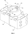
- FIG. 6 illustrates the split mold insert 114 in perspective view with the split mold insert halves 116, 118 oriented so that their respective mating faces 190, 192 are visible. It will be appreciated that the view of FIG. 6 is for illustration purposes only and that the split mold insert halves 116, 118 are not actually used in this orientation.
- Each of the complementary mating faces 190, 192 has an inner face region 200, 220 and an outer face region 204, 224 separated by an offset 202, 222 respectively.
- the inner face region 200, 220 occupies a first plane P1 and the outer face region 204, 224 occupies a different plane P2 (see FIG. 5 ).
- the offset 202, 222 defines a step or jog in the mating face. For this reason, the illustrated mating faces 190, 192 may be considered as offset mating faces.
- mating face 190 of the first split mold insert half 116 defines (on each side of mold cavity 105) an inner face region 200, an offset 202, and an outer face region 204 (see FIG. 6 ).
- the inner face region 200 is adjacent to the mold cavity 105, and terminates partly at the shutoff face 142 and partly at the outer surface 139 of the male projecting portion 132.
- the outer face region 204 is on an opposite side of the offset 202 from the inner face region 200. Because the outer face region 204 of split mold insert half 116 protrudes relative to the inner face region 200, the split mold insert half 116 of FIG. 6 may be considered to define a slot or recess bounded laterally by the protruding outer face regions 204.
- the offset 202 has a J-shape characterized by a first, substantially straight portion 206 and a second, curved portion 208.
- the first portion 206 is elongate and is substantially parallel to the operational axis A of the mold stack 103, and the second, curved portion 208 diverges away from the operational axis A.
- the second portion 208 of the offset 202 terminates at the outer surface 139 of the male projecting portion 132.
- the offset 202 terminates at a frustoconical outer surface 139 of the male projecting portion 132, between a rounded peripheral edge of the annular shutoff face 142 (at the top of the male projecting portion 132) and the flared base at the bottom of the male projecting portion 132 (where the male projecting portion 132 connects with the remainder of the split mold insert 114).
- the complementary mating face 192 of the second split mold insert half 118 similarly defines (on each side of mold cavity 105) an inner face region 220 adjacent to mold cavity 105, an offset 222, and an outer face region 224 on an opposite side of the offset 222 from the inner face regions 220.
- the inner face region 220 terminates partly at the shutoff face 142 and partly at the outer surface 139 of male projecting portion 132.
- the inner face region 220 protrudes relative to the outer face region 224. Therefore, the split mold insert half 118 may be considered to define a key (the two protruding inner face regions 220 collectively) that fits into the slot defined between the outer face regions 204 of the other split mold insert half 116.
- the offset 222 in mating face 192 has a J-shape complementary to that of offset 202 of split mold insert half 116.
- the offset 222 is characterized by a first, substantially straight portion 226 and a second, curved portion 228.
- the first portion 226 is elongate and is parallel to the operational axis A of the mold stack 103.
- the second, curved portion 228 diverges away from the axis A and terminates at the outer surface 139 of the male projecting portion 132.
- the inner face region 220 of split mold insert half 118 includes a vent 230 near the portion of mold cavity 105 that defines the neck finish 119 (relief portion) of the preform 101.
- the vent 230 is intended to vent air during melt injection, with a view to decreasing the likelihood of trapped air in the relief areas of the mold cavity 105. Trapped air can result in defects in the neck finish 119 of the preform 101 and is therefore generally undesirable.
- the example vent 230 has a serpentine shape, which follows the contours of the molding surface for molding the neck finish 119.
- the flat face of the serpentine shape is slightly recessed or indented relative to the remainder of inner face region 220.
- the degree of indentation is deliberately chosen so that, when the inner face region 220 is mated, in a molding configuration, with flat complementary inner face region 200 of the other split mold insert half 116 (e.g. as in FIGS. 4 and 5 ), the vent 230 defines a gap that permits air, but not melt (in any substantial amount), to pass therethrough.
- the width of the gap that is suitable for causing vent 230 to vent air while blocking melt may depend upon the properties of the melt to be used in mold stack 103.
- the gap may be in the range of 30-40 microns.
- An air collector groove 232 is disposed adjacent to vent 230 ( FIG. 6 ). Air collector groove 232 collects air vented from the mold cavity via vent 230. The air collector groove 232 is recessed or indented relative to the remainder of inner face region 220 to an even greater extent than vent 230. This indentation facilitates egress of air from molding cavity 105 via vent 230. The air collector groove 232 aligns with another groove 234 in the outer face region 204 of the complementary mating face 190, which channels air towards an outlet for venting to the atmosphere.
- split mold insert halves 116, 118 are held together in the molding configuration despite the exertion of an opposing outward force pressurized melt within the neck finish area of the molding cavity 105.
- shutoff faces 133 and 142 define a parting line between the cavity insert 106 and the split mold insert 114.
- the term "parting line" as used herein refers to a junction between two mold stack components that prevents melt from passing therethrough and, unlike a vent, is not intended or otherwise relied upon to vent gas therethrough.
- vent residue may accumulate within the vent 230 defined between the split mold insert halves 116, 118.
- the residue may for example be made up of molding material dust, contaminants or other particles.
- removal of vent residue may be performed by taking the molding system out of operation, opening the mold stacks and manually scraping and/or cleaning the affected vent surfaces.
- a possible disadvantage of such an approach is the corresponding loss of production capacity and the manual labor involved and significant risk of damaging the mold.
- the example mold stack 103 is configurable between the standard molding configuration, discussed above, and a vent-cleaning (or simply "cleaning") configuration.
- a vent-cleaning (or simply "cleaning") configuration In the cleaning configuration, mold stack surfaces that normally cooperate to define vents therebetween are slightly separated from one another to allow melt to enter therebetween. Put another way, vents to be cleaned are reconfigured to become extensions of the molding cavity.
- melt from the molding cavity enters the widened vents as "intentional flashing.” Residue within the vents adheres to, or becomes incorporated with, the flashing and may thus be removed when the molded article, complete with integral flashing, is ejected from the molding cavity.
- Such cleaning cycles may be scheduled to occur as needed, e.g. at predetermined time intervals, after a predetermined number of molding cycles, or on demand.
- FIGS. 7-11 illustrate the example mold stack 103, or components thereof, in a cleaning configuration. More specifically, FIG. 7 is a cross-sectional elevation view of the mold stack 103 similar to that of FIG. 1 but in a cleaning configuration, with the core insert 110 omitted for better visibility of split mold insert 114.
- FIG. 8 provides a close-up cross-sectional elevation view, similar to FIG. 3 , of a portion of mold stack 103 illustrating interaction between the split mold insert 114, cavity flange 109 and cavity insert 106 when in the cleaning configuration.
- FIGS. 9 and 10 illustrate split mold insert 114 in the cleaning configuration in perspective view and plan view, respectively, in isolation from other mold stack components.
- FIG. 11 schematically depicts the split mold insert 114 of FIG. 10 in the cleaning configuration using a simplified representation wherein certain features (e.g. gaps) are exaggerated for improved comprehensibility.
- the mold stack 103 depicted therein differs from the one depicted in FIGS. 1 and 3 in that gaps G1 and G2 have been introduced on opposite sides of the split mold insert 114.
- the first gap G1 is between the split mold insert 114 and the core ring 111.
- the second gap G2 is between the split mold insert 114 and the cavity insert 106.
- the gaps may be introduced by a shut height adjustment mechanism associated with the mold 100 (not depicted).
- the gap G2 is formed between the shutoff face 133 of cavity insert 106 and shutoff face 142 of split mold insert 114.
- the extent of gap G2 is sufficient for melt to enter between the shutoff faces 133, 142.
- the gap G2 acts as an extension of the mold cavity 105, with the shutoff faces 133, 142 accordingly behaving as molding surfaces.
- the split mold insert halves 116, 118 are free to separate laterally (vertically in FIG. 8 ) to a limited extent to form a gap G3 between their mating faces 190, 192. Separation may for example be responsive to an injection of pressurized melt into the mold cavity 105.
- the tapered female receptacle 130 of cavity flange 109 may limit the degree of separating of the split mold insert halves 116, 118 by limiting a degree of separating of the associated halves 136, 138 of the tapered male portion 132 (see FIG. 8 ).
- proximal portion 141 of split line 143 between the split mold insert halves 116, 118 has widened to form gap G3 and that the distal portion 147 of split line 143 has similarly widened to form gap G3.
- FIG. 11 provides a simplified schematic view of the split mold insert 114, in the cleaning configuration, in the same general view and orientation as FIG. 10 .
- FIG. 11 is intended to promote a better understanding of how the various features of complementary mating faces 190, 192 of split mold insert halves 116, 118 respectively interact when the split mold insert 114 is in the cleaning configuration. It will be appreciated that the dimensions of FIG. 11 are not to scale and that some features (e.g. gap sizes) are exaggerated to facilitate comprehension.
- gap G3 is intentionally set, e.g. through suitable dimensioning of gaps G1 and/or G2 using a shut height adjustment mechanism, to be wide enough to allow melt to flow therein.
- the separated inner face regions 200, 220 of mating faces 190, 192 respectively define an extension 170 of the molding cavity 105 on opposite side of the cavity 105.
- complementary (opposing) outer face region 204, 224 are separated by the same extent (G3) as the inner face regions 200, 220 when the split mold insert half 114 is in the cleaning configuration.
- the resultant distal gap 172 is unbounded at a periphery of split mold insert 114 ( FIG. 10 ), presenting a risk that any melt entering the distal gap may flash uncontrollably from the split mold insert 114.
- Possible disadvantages of uncontrolled flashing from distal gap 172 may include: wastage of melted molding material; increased risk of fouling mold stack areas that should be clean for proper mold operation; and increased risk of "daisy chaining" of adjacent molded articles (whereby flashing from adjacent mold stacks merges and causes adjacent preforms, which are intended to be formed as discrete articles, to unintentionally become connected in rows or chains).
- the offsets 202, 222 cooperate to form a melt barrier or "fence." Because the offsets 202, 222 are parallel, rather than orthogonal, to the separation dimension L (see FIG. 11 ), separation of the split mold insert halves 116, 118 into their cleaning configuration does not cause complementary offsets 202, 222 to separate like the inner and outer face regions 200, 220 and 204, 224. Instead, the offsets 202, 222 slide relative to one another, with no change in their separation distance D. The substantially constant separation distance D between the offsets 202, 222 (i.e.
- Suitable dimensioning of separation distance D may allow air, but not melt, to pass between offsets 202, 222, so that the offsets collectively define vents on either side of mold cavity 105 over their entire lengths. However, this is not absolutely required.
- FIGS. 12 and 13 illustrate two stages of injection molding a preform 101' (i.e. preform 101 plus intentional flashing) using the mold stack 103 in the cleaning configuration.
- FIGS. 12 and 13 show three components of mold stack 103: cavity insert 106, cavity flange 109, and split mold insert half 118. The first two components are illustrated in transverse cross section, with only the lower portion of cavity insert 106 being visible. The latter component, i.e. split mold insert half 118, is shown in full but without the complementary split mold insert half 116. Core insert 110 is omitted for clarity.
- inflowing melt 300 which flows from the top down in FIG. 12 , has filled the cylindrical upper portion of mold cavity 105 in the area of cavity insert 106.
- the melt 300 has further entered into the annular gap G2 formed between the downwardly facing annular shutoff face 133 of cavity insert 106 and the upwardly facing annular shutoff face 142 of split mold insert half 118.
- the gap G2 is peripherally bounded by the tapered female receptacle 130 of cavity flange 109 (see also FIG. 8 ).
- the outer surface 139 of the male projecting portion 132 cooperates with the tapered female receptacle 130 to provide a melt barrier at an underside of a periphery of annular gap G2 (see FIG. 12 ). As such, further radial melt flow is precluded.
- the melt within gap G2 accordingly forms an annular flange 302 that extends from, and is integral with, preform 101'.
- the melt 300 has continued to flow downwardly within split mold insert 114 (of which only split mold insert half 118 is visible in FIG. 12 ). Due to the separation of the split mold insert halves 116, 118 as depicted in FIGS. 7-11 , some melt 300 has begun to flow laterally into the mold cavity extension 170 defined between the inner face region 220 of split mold insert half 118 and the inner face region 200 of split mold insert half 116 (see FIG. 11 ).
- the preform 101' is fully formed.
- the mold cavity extension 170 between inner face regions 200 and 220, on either side of mold cavity 105, has been entirely filled with melt, forming wings 304 (intentional flashing) whose thickness is determined by the width of gap G3.
- the wings 304 are integral with annular flange 302 and are flared outwardly at their upper ends. The flaring is due to the outward divergence of offsets 202, 222 away from mold cavity 105 and towards the outer surface 139 of the male projecting portion 132.
- vents 230 may be incorporated into wings 304 for removal upon ejection of preform 101'.
- a vent-cleaning purpose may thereby be achieved.
- the preform 101' may have the appearance shown in the perspective view of FIG. 14 .
- relief features resulting from vent 230 and groove 232 which relief features are disposed on an underside of wings 304 as they appear in FIG. 14 , may be visible from the opposite side of the wings 304 in FIG. 14 in view of a translucency of the molding material from the example preform 101' is made.
- FIG. 15 an alternative split mold insert 314 is depicted in FIG. 15 in a similar perspective view to what is provided in FIG. 6 .
- the split mold insert 314 illustrated in FIG. 15 is, in most respects, similar to the split mold insert 114 described above.
- the split mold insert 314 is split into two halves 316, 318, each having a respective offset mating face 390, 392.
- the mating faces 390, 392 are complementary.
- the mating face 390 of first split mold insert half 316 defines, on each side of mold cavity 305, an inner face region 400, an offset 402, and an outer face region 404.
- the inner face region 400 is adjacent to the mold cavity 305 and terminates partly at the shutoff face 342 and partly at a rounded transition region 343 adjacent to the shutoff face 342.
- the outer face region 404 is on an opposite side of the offset 402 from the inner face region 400 and terminates partly at the outer surface 339 of male projecting portion 332 and partly at a rounded peripheral edge 343 adjacent of the shutoff face 342.
- the outer face regions 404 protrude relative to the inner face regions 400.
- the complementary mating face 392 of the second split mold insert half 318 similarly defines, on each side of mold cavity 305, an inner face region 420 adjacent to mold cavity 305, an offset 422, and an outer face region 424 on an opposite side of the offset 422 from the inner face region 420.
- the offsets 402, 422 of split mold insert are substantially straight, terminating at the transition area 343 between shutoff face 342 and outer surface 339, rather than at the outer surface 339 of the male projecting portion 332 (see FIG. 15 ; see also the perspective close-up view of the split mold insert 314 of FIG. 16 ).
- melt from mold cavity 305 or from mold cavity extension 370 i.e. the gap formed between opposing inner face regions 400, 420 when the split mold insert 314 is in the cleaning configuration
- distal gap 372 i.e. the gap formed between opposing outer face region 404, 424 when the split mold insert 314 is in the cleaning configuration.
- the innermost extent of the distal gap 372 is open to the influx of melt from the gap between shutoff face 342 and the shutoff face of the adjacent cavity insert (not depicted).
- the distal gap 172 terminates fully in the outer surface 139 of the male projecting portion 132, with the result that melt is blocked from entering the distal gap 172 (see e.g. FIG. 11 ).
- the result may be a daisy chaining of adjacent preforms into an array 450 of interconnected preforms, as depicted in the perspective view of FIG. 17 for example.
- This potential risk may not be well-appreciated by the person of ordinary skill, e.g. because vent-cleaning configurations of split mold inserts are relatively new to the industry and/or because vent cleaning may be performed relatively infrequently.
- Disadvantages of daisy chaining may include the unexpected interruption of the molding cycle, resulting from cleaning parts that cannot be fully ejected, or the partial ejection of cleaning parts, fooling the machine's part detection sensors, allowing the mold to close with parts of the molded article remaining between the split mold inserts or other areas in and around them, and resulting in fouled mold stacks or other mold areas that should be clean for proper mold operation.
- the offsets 202, 222 in the complementary mating faces 190, 192 are J-shaped (see e.g. FIG. 6 ). It will be appreciated that the offsets of other split mold insert embodiments may have other shapes.
- FIG. 18 shows an alternative embodiment of split mold insert 514 in which the offsets are substantially L-shaped.
- the split mold insert may for example be substitutable for split mold insert 114 in mold stack 103.
- the split mold insert 514 is shown in perspective view, with the two halves 516, 518 oriented so that their respective mating faces 590, 592 are visible.
- the mating face 590 of first split mold insert half 516 defines, on each side of mold cavity 505, an inner face region 600, an offset 602, and an outer face region 604.
- the inner face region 600 is adjacent to the mold cavity 505 and terminates partly at the shutoff face 542 and partly at the outer surface 539 of tapered male projecting portion 532.
- the outer face region 604 is on an opposite side of the offset 602 from the inner face region 600 and terminates (at least in part) at the outer surface 539 of male projecting portion 532.
- the outer face regions 604 protrude relative to the inner face regions 600.
- the complementary mating face 592 of the second split mold insert half 518 similarly defines, on each side of mold cavity 505, an inner face region 620 adjacent to mold cavity 505, an offset 622, and an outer face region 624 on an opposite side of the offset 622 from the inner face region 620.
- each of the offsets 602, 622 of the present embodiment has an L-shape characterized by a first, longer straight portion 606, 626 and a second, shorter straight portion 608, 628 extending orthogonally from the longer portion 606.
- the first portion 606 is substantially parallel to the operational axis A of the mold stack 103, which extends through the middle of the mold cavity 505 (in a similar manner as axis A extends through mold cavity 105 of FIG. 6 ).
- the second portion 608, 628 of the offset 602, 622 is substantially orthogonal to the axis A (substantially parallel to shutoff face 542) and terminates at the outer surface 539 of the male projecting portion 532.
- FIG. 19 shows a further alternative embodiment of split mold insert 714 in which portions of the offsets are slightly bent at an obtuse angle of about 170 degrees.
- the split mold insert 714 may similarly be substitutable for split mold insert 114 in mold stack 103.
- the split mold insert 714 is shown in perspective view, with the two halves 716, 718 oriented so that their respective mating faces 790, 792 are visible.
- the mating face 790 of first split mold insert half 716 defines, on each side of mold cavity 705, an inner face region 800, an offset 802, and an outer face region 804.
- the inner face region 800 is adjacent to the mold cavity 705 and terminates partly at the shutoff face 742 and partly at the outer surface 739 of tapered male projecting portion 732.
- the outer face region 804 is on an opposite side of the offset 802 from the inner face region 800 and terminates (at least in part) at the outer surface 739 of male projecting portion 732.
- the outer face regions 804 protrude relative to the inner face regions 800.
- the complementary mating face 792 of the second split mold insert half 718 similarly defines, on each side of mold cavity 705, an inner face region 820 adjacent to mold cavity 705, an offset 822, and an outer face region 824 on an opposite side of the offset 822 from the inner face region 820.
- each of the offsets 802, 822 of the present embodiment is characterized by a first, longer straight portion 806, 826 and a second, shorter straight portion 808, 828 extending at an obtuse angle from the longer portion 806, 826 respectively.
- each portion 806, 826 and 808, 828 is substantially parallel to the portion of molding surface 810 of the molding cavity 705 to which it is adjacent (the upper portion of the mold cavity 705 being slightly outwardly flared in the present embodiment).
- the portions 808, 828 may also be substantially parallel to the operational axis A of the mold stack 103.
- the second portion 806, 826 of the offset 802, 822 terminates at the outer surface 739 of the male projecting portion 732. It will be appreciated that the portion 806, 826 of offsets 802, 822 does not necessarily have to be longer than the portion 808, 828 respectively.
- the former could be of equal length or shorter than the latter in alternative embodiments.
- split mold inserts 514, 714 of FIGS. 18 and 19 for preventing uncontrolled flashing within the distal gap formed between outer face regions 604, 624 and 804, 824 is analogous to that of split mold insert 114.
- the outer surface 539, 739 of the male projecting portion 532, 732 cooperates with the tapered female receptacle 130 of cavity flange 109 to provide a melt barrier.
- the interface acts as a fence, blocking any melt from flowing between the offsets 602, 622 and 802, 822. Instead, the melt may be guided towards the melt barrier.
- the example split mold insert 114 of FIGS. 1 and 3-13 is designed for use in core lock type mold stack 103. It will be appreciated that similar split mold inserts could be used with other mold stacks types, such as cavity lock type mold stacks (i.e. the split insert has a female taper on the bottom thereof), to mitigate the above-described type of uncontrolled flashing.
- split mold inserts are depicted as being split into two halves, alternative embodiments of split mold insert may be split into a larger number of parts separable for molded article ejection.
- each of the inner face regions 200, 220, 600, 620 and 800, 820 occupies a first plane (e.g. plane P1 in the case of split mold insert 114) and each of the outer face regions 204, 224, 604, 624 and 804, 824 occupied a different plane (e.g. plane P2 in the case of split mold insert 114—see FIG. 5 ).
- the inner and outer face regions of split mold insert part could occupy the same plane.
- one offset e.g. offset 202, 602 and 802 could be a tongue and the complementary offset (e.g. offset 122, 622 and 822) could be a groove.
- the male projecting portions of the split mold insert embodiments disclosed herein are frustoconical.
- the male projecting portions could have other shapes. Tapered shapes may facilitate alignment of the split mold insert with adjacent mold stack components having corresponding female receptacles.
- the shape of some male projecting portion embodiments could be non-tapered (e.g. cylindrical).
Landscapes
- Engineering & Computer Science (AREA)
- Mechanical Engineering (AREA)
- Manufacturing & Machinery (AREA)
- Physics & Mathematics (AREA)
- Geometry (AREA)
- Moulds For Moulding Plastics Or The Like (AREA)
- Injection Moulding Of Plastics Or The Like (AREA)
Claims (13)
- Geteilter Formeinsatz (114, 514, 714) zur Definition eines Reliefabschnitts eines Formgegenstands, umfassend:einen Körper, der einen Formhohlraum (105, 505, 705) für den Reliefabschnitt (119) des Formgegenstands (101) definiert, wobei der Körper einen positiven vorspringenden Abschnitt (132, 532, 732) mit einer Sperrfläche (142, 542, 742) aufweist, wobei die Sperrfläche selektiv in einer Spritzgießkonfiguration des geteilten Formeinsatzes eine Trennlinie zu einer benachbarten Etagenwerkzeug-Komponente (106) und in einer Reinigungskonfiguration des geteilten Formeinsatzes eine Formoberfläche definiert, wobei der positive vorspringende Abschnitt eine äußere Oberfläche (139, 539, 739) aufweist, die dazu ausgestaltet ist, mit einem negativen Aufnehmer (130) zusammenzuwirken, welcher der benachbarten Etagenwerkzeug-Komponente zugeordnet ist, um in der Reinigungskonfiguration des geteilten Formeinsatzes eine Schmelzebarriere bereitzustellen,wobei der Körper in eine Vielzahl von Teilen des geteilten Formeinsatzes (116, 118, 516, 518, 716, 718) unterteilt ist, die zum Auswerfen des Formgegenstands trennbar sind, wobei jeder Teil des geteilten Formeinsatzes (116, 118, 516, 518, 716, 718) eine Passfläche (190, 192, 590, 592, 790, 792) zur Passung mit einer komplementären Passfläche eines benachbarten der Teile des geteilten Formeinsatzes aufweist, wobei die Passfläche eine innere Flächenregion (200, 220, 600, 620, 800, 820) benachbart zu dem Formhohlraum, einen Versatz (202, 222, 602, 622, 802, 822) und eine äußere Flächenregion (204, 224, 604, 624, 804, 824) an einer der inneren Flächenregion gegenüberliegenden Seite des Versatzes aufweist,wobei der Versatz eines jeden Teils des geteilten Formeinsatzes (116, 118, 516, 518, 716, 718) einen ersten Abschnitt (206, 226, 606, 626, 806, 826) aufweist, der im Wesentlichen parallel zu einer Achse (A) des Teils des geteilten Formeinsatzes ist;dadurch gekennzeichnet, dass der Versatz eines jeden Teils des geteilten Formeinsatzes (116, 118, 516, 518, 716, 718) einen zweiten Abschnitt (208, 228, 608, 628, 808, 828) aufweist, der von der Achse zu der äußeren Oberfläche des positiven vorspringendes Abschnitts (139, 539, 739) abweicht und an der äußeren Oberfläche endet, wobei zumindest ein Teil der inneren Flächenregion eines jeden Teils des geteilten Formeinsatzes an der Sperrfläche (142, 542, 742) des positiven vorspringenden Abschnitts endet, und wobei der Versatz eines jeden Teils des geteilten Formeinsatzes (116, 118, 516, 518, 716, 718) dazu ausgestaltet ist, mit dem Versatz des benachbarten der Teile des geteilten Formeinsatzes (116, 118, 516, 518, 716, 718) zusammenzuwirken, um zu verhindern, das Schmelze zwischen den Versätzen hindurchgelangt, und um die Schmelze zu der Schmelzebarriere hin zu führen.
- Geteilter Formeinsatz nach Anspruch 1, wobei die inneren und äußeren Flächenregionen in unterschiedlichen Ebenen (P1, P2) liegen.
- Geteilter Formeinsatz nach Anspruch 2, wobei der Versatz senkrecht auf jede der Ebenen steht, in welchen die innere Flächenregion und die äußere Flächenregion liegen.
- Geteilter Formeinsatz nach Anspruch 1, wobei der zweite Abschnitt des Versatzes (608, 628) im Wesentlichen senkrecht zu dem ersten Abschnitt des Versatzes (606, 626) ist.
- Geteilter Formeinsatz nach Anspruch 4, wobei der Versatz eines jeden Teils des geteilten Formeinsatzes im Wesentlichen L-förmig ist.
- Geteilter Formeinsatz nach Anspruch 1, wobei der zweite Abschnitt des Versatzes (208, 228) eines jeden Teils des geteilten Formeinsatzes zumindest zum Teil gekrümmt ist.
- Geteilter Formeinsatz nach Anspruch 6, wobei der Versatz (202, 222) eines jeden Teils des geteilten Formeinsatzes im Wesentlichen J-förmig ist.
- Geteilter Formeinsatz nach einem der vorhergehenden Ansprüche, wobei die Versätze der komplementären Passflächen einander überlappen und einen Spalt dazwischen definieren, wobei der Spalt im Wesentlichen konstant ist, unabhängig davon, ob der geteilte Formeinsatz in der Reinigungskonfiguration oder in einer Spritzgießkonfiguration ist, wobei der Spalt eine Entlüftung definiert, die den Durchgang von Gas dorthindurch erlaubt, den Durchgang von Schmelze jedoch verhindert.
- Geteilter Formeinsatz nach einem der vorhergehenden Ansprüche, wobei der positive vorspringende Abschnitt des geteilten Formeinsatzes sich verjüngt.
- Geteilter Formeinsatz nach einem der vorhergehenden Ansprüche, wobei die Sperrfläche des positiven vorspringenden Abschnitts ringförmig ist und einen abgerundeten umlaufenden Rand aufweist, wobei der positive vorspringende Abschnitt eine aufgeweitete Basis aufweist, und wobei der Versatz in der kegelstumpfförmigen äußeren Oberfläche des positiven vorspringenden Abschnitts zwischen dem abgerundeten umlaufenden Rand der Sperrfläche und der aufgeweiteten Basis des positiven vorspringenden Abschnitts endet,
- Geteilter Formeinsatz nach einem der vorhergehenden Ansprüche, wobei die Vielzahl von Teilen des geteilten Formeinsatzes ein Paar von Hälften des geteilten Formeinsatzes ist.
- Etagenwerkzeug (103) zur Formung eines Formgegenstands (101) mit einem Reliefabschnitt (119), umfassend:einen geteilten Formeinsatz (114, 514, 714) nach einem der vorhergehenden Ansprüche; undeine benachbarte Etagenwerkzeug-Komponente (106), die einen zugehörigen negativen Aufnehmer (130) aufweist,wobei der geteilte Formeinsatz eine Reinigungskonfiguration aufweist, in welcher:die Sperrfläche des positiven vorspringenden Abschnitts als eine Formoberfläche wirkt;der positive vorspringende Abschnitt mit dem negativen Aufnehmer zusammenwirkt, um eine Schmelzebarriere zu definieren;die komplementären inneren Flächenregionen der Teile des geteilten Formeinsatzes beabstandet sind, um eine Erweiterung des Formhohlraums (170) zu bilden, wobei die Formhohlraum-Erweiterung zumindest zum Teil an der Sperrfläche des geteilten Formeinsatzes endet, die als die Formoberfläche wirkt; unddie komplementären Versätze zusammenwirken, um zu verhindern, dass Schmelze dorthindurch gelangt, und um Schmelze zu der Schmelzebarriere hin zu führen.
- Etagenwerkzeug nach Anspruch 12, wobei die benachbarte Etagenwerkzeug-Komponente ein Hohlraumeinsatz (106) ist, und wobei der negative Aufnehmer in einem Hohlraumflansch (109) definiert ist, der dem Hohlraumeinsatz zugehörig ist.
Priority Applications (1)
| Application Number | Priority Date | Filing Date | Title |
|---|---|---|---|
| EP21190606.0A EP3925757B1 (de) | 2016-12-14 | 2017-11-22 | Geteilter formeinsatz zur herstellung eines reliefabschnitts eines formartikels und formstapel damit |
Applications Claiming Priority (2)
| Application Number | Priority Date | Filing Date | Title |
|---|---|---|---|
| US201662433883P | 2016-12-14 | 2016-12-14 | |
| PCT/CA2017/051396 WO2018107273A1 (en) | 2016-12-14 | 2017-11-22 | Split mold insert for forming a relief portion of a molded article and mold stack incorporating same |
Related Child Applications (2)
| Application Number | Title | Priority Date | Filing Date |
|---|---|---|---|
| EP21190606.0A Division-Into EP3925757B1 (de) | 2016-12-14 | 2017-11-22 | Geteilter formeinsatz zur herstellung eines reliefabschnitts eines formartikels und formstapel damit |
| EP21190606.0A Division EP3925757B1 (de) | 2016-12-14 | 2017-11-22 | Geteilter formeinsatz zur herstellung eines reliefabschnitts eines formartikels und formstapel damit |
Publications (3)
| Publication Number | Publication Date |
|---|---|
| EP3554788A1 EP3554788A1 (de) | 2019-10-23 |
| EP3554788A4 EP3554788A4 (de) | 2020-08-12 |
| EP3554788B1 true EP3554788B1 (de) | 2023-07-19 |
Family
ID=62557706
Family Applications (2)
| Application Number | Title | Priority Date | Filing Date |
|---|---|---|---|
| EP17881792.0A Active EP3554788B1 (de) | 2016-12-14 | 2017-11-22 | Geteilter formeinsatz zur herstellung eines reliefabschnitts eines formartikels und formstapel damit |
| EP21190606.0A Active EP3925757B1 (de) | 2016-12-14 | 2017-11-22 | Geteilter formeinsatz zur herstellung eines reliefabschnitts eines formartikels und formstapel damit |
Family Applications After (1)
| Application Number | Title | Priority Date | Filing Date |
|---|---|---|---|
| EP21190606.0A Active EP3925757B1 (de) | 2016-12-14 | 2017-11-22 | Geteilter formeinsatz zur herstellung eines reliefabschnitts eines formartikels und formstapel damit |
Country Status (5)
| Country | Link |
|---|---|
| US (1) | US11794375B2 (de) |
| EP (2) | EP3554788B1 (de) |
| JP (1) | JP6884864B2 (de) |
| CN (2) | CN108215069B (de) |
| WO (1) | WO2018107273A1 (de) |
Families Citing this family (6)
| Publication number | Priority date | Publication date | Assignee | Title |
|---|---|---|---|---|
| CN108215069B (zh) * | 2016-12-14 | 2020-10-23 | 赫斯基注塑系统有限公司 | 对开式模具插入件以及模具堆叠 |
| EP3898164B1 (de) | 2018-12-11 | 2024-05-29 | Husky Injection Molding Systems Ltd. | Spritzgussform zur führung einer klemmlast durch formstapel |
| IT201900000667A1 (it) * | 2019-01-16 | 2020-07-16 | Sipa Progettazione Automaz | Componente di stampo per preforme |
| USD958208S1 (en) | 2019-06-04 | 2022-07-19 | Husky Injection Molding Systems Ltd. | Molding machine part |
| IT202200021594A1 (it) * | 2022-10-19 | 2024-04-19 | Sipa Progettazione Automaz | Preforma di un contenitore in plastica |
| EP4673294A1 (de) * | 2023-02-27 | 2026-01-07 | Husky Injection Molding Systems Luxembourg IP Development S.à.r.l | Formen, formanordnungen und stapelkomponenten |
Family Cites Families (37)
| Publication number | Priority date | Publication date | Assignee | Title |
|---|---|---|---|---|
| CH387884A (de) | 1961-11-21 | 1965-02-15 | Buehler Ag Geb | Formschliessvorrichtung |
| US4133260A (en) | 1976-10-15 | 1979-01-09 | Packaging Industries, Inc. | Shut height adjustment mechanism |
| US4971803A (en) | 1985-04-08 | 1990-11-20 | California Institute Of Technology | Lamellar vesicles formed of cholesterol derivatives |
| US4790173A (en) | 1987-05-29 | 1988-12-13 | Amp Incorporated | Shut height adjustment means in pressing apparatus |
| US5002479A (en) | 1989-05-30 | 1991-03-26 | John Brown Inc. | Apparatus for adjusting the shut height of a mold in a differential pressure forming machine |
| JPH03184808A (ja) | 1989-12-15 | 1991-08-12 | Ube Ind Ltd | 成形機の型締装置 |
| JP2867519B2 (ja) | 1989-12-28 | 1999-03-08 | 東洋製罐株式会社 | 射出成形用金型及びその保守方法 |
| US5397230A (en) | 1993-08-04 | 1995-03-14 | Gencorp Inc. | Vent apparatus for an injection mold |
| EP0704292A4 (de) | 1994-03-30 | 1996-12-27 | Sankyokasei Kabushiki Kaisha | Giessverfahren und giessvorrichtung für kunststoff |
| US5536166A (en) | 1995-02-10 | 1996-07-16 | Husky Injection Molding Systems Ltd. | Injection molding machine with open access to the mold area |
| US5753153A (en) | 1996-01-02 | 1998-05-19 | Husky Injection Molding Systems Ltd. | Method for mold clamping units |
| CA2160644C (en) | 1995-10-16 | 2005-05-24 | Jobst Ulrich Gellert | Cooled thread split inserts for injection molding preforms |
| US5964134A (en) | 1997-06-11 | 1999-10-12 | Arends; Albert W. | Trim apparatus and method for trimming an article from a thermoplastic sheet |
| US6258311B1 (en) * | 1997-08-25 | 2001-07-10 | Velcro Industries B.V. | Forming mold cavities |
| US5884520A (en) | 1997-11-17 | 1999-03-23 | The Whitaker Corporation | Die set having shut height adjust and stripper plate actuator mechanisms |
| US6055904A (en) | 1998-12-28 | 2000-05-02 | Brown Machine, Llc | Shut height adjustment and crank support arrangements and methods for a thermoforming press |
| US6200122B1 (en) | 1999-08-03 | 2001-03-13 | Brown Machine, Llc. | Thermoforming apparatus with improved press |
| DE19941925B4 (de) | 1999-09-03 | 2007-11-29 | Schuler Pressen Gmbh & Co. Kg | Verstellplatte für eine Presse |
| US20030070693A1 (en) | 2001-10-15 | 2003-04-17 | Scott Stratford | Method for cleaning and injection mold |
| US7128865B2 (en) | 2003-12-17 | 2006-10-31 | Husky Injection Molding Systems Ltd. | Apparatus and method for two stage ejection of a molded preform from a mold |
| US7481642B2 (en) | 2004-04-23 | 2009-01-27 | Husky Injection Molding Systems Ltd. | Method and apparatus for controlling a vent gap with active material elements |
| ITRE20040127A1 (it) | 2004-10-12 | 2005-01-12 | Sacmi | Metodo e gruppo per la formatura a compressione di preforme per contenitori in materiale polimerico |
| CA2509181C (en) * | 2005-06-03 | 2009-04-28 | Husky Injection Molding Systems Ltd. | A mold split insert |
| US7381049B2 (en) | 2006-03-08 | 2008-06-03 | Husky Injection Molding Systems Ltd. | Injection mold |
| JP2008093727A (ja) | 2006-10-16 | 2008-04-24 | Sintokogio Ltd | 鋳型 |
| US7452199B2 (en) | 2006-12-15 | 2008-11-18 | D-M-E Company | Apparatus for injection molding |
| EP2343176A1 (de) | 2010-01-11 | 2011-07-13 | La Seda De Barcelona S.A. | Spritzgießwerkzeugstapel und Formvorrichtung |
| JP5684498B2 (ja) | 2010-06-15 | 2015-03-11 | 住友重機械工業株式会社 | 射出成形方法及び射出成形機 |
| CN103097102B (zh) * | 2010-08-12 | 2015-11-25 | 赫斯基注塑系统有限公司 | 模制设备 |
| EP3827959B1 (de) * | 2011-08-04 | 2023-07-26 | Husky Injection Molding Systems Ltd. | Formkomponente mit einer rückstandsreinigungsfunktion |
| USD699769S1 (en) * | 2012-04-10 | 2014-02-18 | Husky Injection Molding Systems, Ltd. | Mold split insert |
| CN104918765B (zh) | 2013-02-01 | 2017-05-17 | 赫斯基注塑系统有限公司 | 具有可调模具闭合高度的模制系统 |
| USD699770S1 (en) | 2013-06-17 | 2014-02-18 | Husky Injection Molding Systems, Ltd. | Mold |
| USD714368S1 (en) | 2013-06-17 | 2014-09-30 | Husky Injection Molding Systems Ltd. | Mold |
| CN105813820B (zh) | 2013-12-19 | 2018-07-13 | 东洋制罐集团控股株式会社 | 塑料材料的成形方法 |
| JP6679627B2 (ja) * | 2015-03-20 | 2020-04-15 | ハスキー インジェクション モールディング システムズ リミテッドHusky Injection Molding Systems Limited | クリーニング構成及びシャットハイト調整機構を備えた金型スタックを有する成形システム |
| CN108215069B (zh) * | 2016-12-14 | 2020-10-23 | 赫斯基注塑系统有限公司 | 对开式模具插入件以及模具堆叠 |
-
2017
- 2017-11-20 CN CN201711160640.9A patent/CN108215069B/zh active Active
- 2017-11-20 CN CN201721555454.0U patent/CN207669673U/zh not_active Withdrawn - After Issue
- 2017-11-22 EP EP17881792.0A patent/EP3554788B1/de active Active
- 2017-11-22 US US16/463,204 patent/US11794375B2/en active Active
- 2017-11-22 WO PCT/CA2017/051396 patent/WO2018107273A1/en not_active Ceased
- 2017-11-22 JP JP2019531909A patent/JP6884864B2/ja active Active
- 2017-11-22 EP EP21190606.0A patent/EP3925757B1/de active Active
Also Published As
| Publication number | Publication date |
|---|---|
| CN108215069A (zh) | 2018-06-29 |
| CN207669673U (zh) | 2018-07-31 |
| JP2020513358A (ja) | 2020-05-14 |
| CN108215069B (zh) | 2020-10-23 |
| EP3554788A4 (de) | 2020-08-12 |
| EP3554788A1 (de) | 2019-10-23 |
| JP6884864B2 (ja) | 2021-06-09 |
| US11794375B2 (en) | 2023-10-24 |
| US20190375134A1 (en) | 2019-12-12 |
| CA3044268A1 (en) | 2018-06-21 |
| EP3925757B1 (de) | 2023-01-25 |
| WO2018107273A1 (en) | 2018-06-21 |
| EP3925757A1 (de) | 2021-12-22 |
Similar Documents
| Publication | Publication Date | Title |
|---|---|---|
| EP3554788B1 (de) | Geteilter formeinsatz zur herstellung eines reliefabschnitts eines formartikels und formstapel damit | |
| CN108189318B (zh) | 用于预制件的模具堆 | |
| US11826936B2 (en) | Molding system having a mold stack with a cleaning configuration and a shut height adjustment mechanism | |
| US8398392B2 (en) | Neck ring for forming a neck portion of a preform and the mold stack incorporating same | |
| CA2815890C (en) | A split mold insert for forming a neck portion of a preform and the mold stack incorporating same | |
| CA3044268C (en) | Split mold insert for forming a relief portion of a molded article and mold stack incorporating same |
Legal Events
| Date | Code | Title | Description |
|---|---|---|---|
| STAA | Information on the status of an ep patent application or granted ep patent |
Free format text: STATUS: THE INTERNATIONAL PUBLICATION HAS BEEN MADE |
|
| PUAI | Public reference made under article 153(3) epc to a published international application that has entered the european phase |
Free format text: ORIGINAL CODE: 0009012 |
|
| STAA | Information on the status of an ep patent application or granted ep patent |
Free format text: STATUS: REQUEST FOR EXAMINATION WAS MADE |
|
| 17P | Request for examination filed |
Effective date: 20190715 |
|
| AK | Designated contracting states |
Kind code of ref document: A1 Designated state(s): AL AT BE BG CH CY CZ DE DK EE ES FI FR GB GR HR HU IE IS IT LI LT LU LV MC MK MT NL NO PL PT RO RS SE SI SK SM TR |
|
| AX | Request for extension of the european patent |
Extension state: BA ME |
|
| DAV | Request for validation of the european patent (deleted) | ||
| DAX | Request for extension of the european patent (deleted) | ||
| A4 | Supplementary search report drawn up and despatched |
Effective date: 20200714 |
|
| RIC1 | Information provided on ipc code assigned before grant |
Ipc: B29C 45/33 20060101AFI20200708BHEP Ipc: B29C 49/06 20060101ALN20200708BHEP Ipc: B29K 105/00 20060101ALN20200708BHEP Ipc: B29C 45/34 20060101ALI20200708BHEP Ipc: B29B 11/14 20060101ALN20200708BHEP |
|
| RAP1 | Party data changed (applicant data changed or rights of an application transferred) |
Owner name: HUSKY INJECTION MOLDING SYSTEMS LUXEMBOURG IP DEVELOPMENT S.A.R.L |
|
| RAP1 | Party data changed (applicant data changed or rights of an application transferred) |
Owner name: HUSKY INJECTION MOLDING SYSTEMS LUXEMBOURG IP DEVELOPMENT S.A.R.L |
|
| STAA | Information on the status of an ep patent application or granted ep patent |
Free format text: STATUS: EXAMINATION IS IN PROGRESS |
|
| 17Q | First examination report despatched |
Effective date: 20210426 |
|
| REG | Reference to a national code |
Ref legal event code: R079 Ipc: B29C0045330000 Ref country code: DE Ref legal event code: R079 Ref document number: 602017071627 Country of ref document: DE Free format text: PREVIOUS MAIN CLASS: B29C0045260000 Ipc: B29C0045330000 |
|
| GRAP | Despatch of communication of intention to grant a patent |
Free format text: ORIGINAL CODE: EPIDOSNIGR1 |
|
| STAA | Information on the status of an ep patent application or granted ep patent |
Free format text: STATUS: GRANT OF PATENT IS INTENDED |
|
| RIC1 | Information provided on ipc code assigned before grant |
Ipc: B29C 49/00 20060101ALN20230117BHEP Ipc: B29B 11/08 20060101ALN20230117BHEP Ipc: B29C 49/06 20060101ALN20230117BHEP Ipc: B29B 11/14 20060101ALN20230117BHEP Ipc: B29K 105/00 20060101ALN20230117BHEP Ipc: B29C 45/34 20060101ALI20230117BHEP Ipc: B29C 45/33 20060101AFI20230117BHEP |
|
| RIC1 | Information provided on ipc code assigned before grant |
Ipc: B29C 49/00 20060101ALN20230126BHEP Ipc: B29B 11/08 20060101ALN20230126BHEP Ipc: B29C 49/06 20060101ALN20230126BHEP Ipc: B29B 11/14 20060101ALN20230126BHEP Ipc: B29K 105/00 20060101ALN20230126BHEP Ipc: B29C 45/34 20060101ALI20230126BHEP Ipc: B29C 45/33 20060101AFI20230126BHEP |
|
| INTG | Intention to grant announced |
Effective date: 20230207 |
|
| GRAS | Grant fee paid |
Free format text: ORIGINAL CODE: EPIDOSNIGR3 |
|
| GRAA | (expected) grant |
Free format text: ORIGINAL CODE: 0009210 |
|
| STAA | Information on the status of an ep patent application or granted ep patent |
Free format text: STATUS: THE PATENT HAS BEEN GRANTED |
|
| P01 | Opt-out of the competence of the unified patent court (upc) registered |
Effective date: 20230516 |
|
| P02 | Opt-out of the competence of the unified patent court (upc) changed |
Effective date: 20230518 |
|
| RAP1 | Party data changed (applicant data changed or rights of an application transferred) |
Owner name: HUSKY INJECTION MOLDING SYSTEMS LTD. |
|
| AK | Designated contracting states |
Kind code of ref document: B1 Designated state(s): AL AT BE BG CH CY CZ DE DK EE ES FI FR GB GR HR HU IE IS IT LI LT LU LV MC MK MT NL NO PL PT RO RS SE SI SK SM TR |
|
| REG | Reference to a national code |
Ref country code: GB Ref legal event code: FG4D |
|
| REG | Reference to a national code |
Ref country code: CH Ref legal event code: EP |
|
| REG | Reference to a national code |
Ref country code: DE Ref legal event code: R096 Ref document number: 602017071627 Country of ref document: DE |
|
| REG | Reference to a national code |
Ref country code: IE Ref legal event code: FG4D |
|
| REG | Reference to a national code |
Ref country code: LT Ref legal event code: MG9D |
|
| REG | Reference to a national code |
Ref country code: NL Ref legal event code: MP Effective date: 20230719 |
|
| REG | Reference to a national code |
Ref country code: AT Ref legal event code: MK05 Ref document number: 1589019 Country of ref document: AT Kind code of ref document: T Effective date: 20230719 |
|
| PG25 | Lapsed in a contracting state [announced via postgrant information from national office to epo] |
Ref country code: NL Free format text: LAPSE BECAUSE OF FAILURE TO SUBMIT A TRANSLATION OF THE DESCRIPTION OR TO PAY THE FEE WITHIN THE PRESCRIBED TIME-LIMIT Effective date: 20230719 |
|
| PG25 | Lapsed in a contracting state [announced via postgrant information from national office to epo] |
Ref country code: GR Free format text: LAPSE BECAUSE OF FAILURE TO SUBMIT A TRANSLATION OF THE DESCRIPTION OR TO PAY THE FEE WITHIN THE PRESCRIBED TIME-LIMIT Effective date: 20231020 |
|
| PG25 | Lapsed in a contracting state [announced via postgrant information from national office to epo] |
Ref country code: IS Free format text: LAPSE BECAUSE OF FAILURE TO SUBMIT A TRANSLATION OF THE DESCRIPTION OR TO PAY THE FEE WITHIN THE PRESCRIBED TIME-LIMIT Effective date: 20231119 |
|
| PG25 | Lapsed in a contracting state [announced via postgrant information from national office to epo] |
Ref country code: SE Free format text: LAPSE BECAUSE OF FAILURE TO SUBMIT A TRANSLATION OF THE DESCRIPTION OR TO PAY THE FEE WITHIN THE PRESCRIBED TIME-LIMIT Effective date: 20230719 Ref country code: RS Free format text: LAPSE BECAUSE OF FAILURE TO SUBMIT A TRANSLATION OF THE DESCRIPTION OR TO PAY THE FEE WITHIN THE PRESCRIBED TIME-LIMIT Effective date: 20230719 Ref country code: PT Free format text: LAPSE BECAUSE OF FAILURE TO SUBMIT A TRANSLATION OF THE DESCRIPTION OR TO PAY THE FEE WITHIN THE PRESCRIBED TIME-LIMIT Effective date: 20231120 Ref country code: NO Free format text: LAPSE BECAUSE OF FAILURE TO SUBMIT A TRANSLATION OF THE DESCRIPTION OR TO PAY THE FEE WITHIN THE PRESCRIBED TIME-LIMIT Effective date: 20231019 Ref country code: LV Free format text: LAPSE BECAUSE OF FAILURE TO SUBMIT A TRANSLATION OF THE DESCRIPTION OR TO PAY THE FEE WITHIN THE PRESCRIBED TIME-LIMIT Effective date: 20230719 Ref country code: LT Free format text: LAPSE BECAUSE OF FAILURE TO SUBMIT A TRANSLATION OF THE DESCRIPTION OR TO PAY THE FEE WITHIN THE PRESCRIBED TIME-LIMIT Effective date: 20230719 Ref country code: IS Free format text: LAPSE BECAUSE OF FAILURE TO SUBMIT A TRANSLATION OF THE DESCRIPTION OR TO PAY THE FEE WITHIN THE PRESCRIBED TIME-LIMIT Effective date: 20231119 Ref country code: HR Free format text: LAPSE BECAUSE OF FAILURE TO SUBMIT A TRANSLATION OF THE DESCRIPTION OR TO PAY THE FEE WITHIN THE PRESCRIBED TIME-LIMIT Effective date: 20230719 Ref country code: GR Free format text: LAPSE BECAUSE OF FAILURE TO SUBMIT A TRANSLATION OF THE DESCRIPTION OR TO PAY THE FEE WITHIN THE PRESCRIBED TIME-LIMIT Effective date: 20231020 Ref country code: FI Free format text: LAPSE BECAUSE OF FAILURE TO SUBMIT A TRANSLATION OF THE DESCRIPTION OR TO PAY THE FEE WITHIN THE PRESCRIBED TIME-LIMIT Effective date: 20230719 Ref country code: AT Free format text: LAPSE BECAUSE OF FAILURE TO SUBMIT A TRANSLATION OF THE DESCRIPTION OR TO PAY THE FEE WITHIN THE PRESCRIBED TIME-LIMIT Effective date: 20230719 |
|
| PG25 | Lapsed in a contracting state [announced via postgrant information from national office to epo] |
Ref country code: PL Free format text: LAPSE BECAUSE OF FAILURE TO SUBMIT A TRANSLATION OF THE DESCRIPTION OR TO PAY THE FEE WITHIN THE PRESCRIBED TIME-LIMIT Effective date: 20230719 |
|
| REG | Reference to a national code |
Ref country code: DE Ref legal event code: R097 Ref document number: 602017071627 Country of ref document: DE |
|
| PG25 | Lapsed in a contracting state [announced via postgrant information from national office to epo] |
Ref country code: ES Free format text: LAPSE BECAUSE OF FAILURE TO SUBMIT A TRANSLATION OF THE DESCRIPTION OR TO PAY THE FEE WITHIN THE PRESCRIBED TIME-LIMIT Effective date: 20230719 |
|
| PG25 | Lapsed in a contracting state [announced via postgrant information from national office to epo] |
Ref country code: SM Free format text: LAPSE BECAUSE OF FAILURE TO SUBMIT A TRANSLATION OF THE DESCRIPTION OR TO PAY THE FEE WITHIN THE PRESCRIBED TIME-LIMIT Effective date: 20230719 Ref country code: ES Free format text: LAPSE BECAUSE OF FAILURE TO SUBMIT A TRANSLATION OF THE DESCRIPTION OR TO PAY THE FEE WITHIN THE PRESCRIBED TIME-LIMIT Effective date: 20230719 Ref country code: EE Free format text: LAPSE BECAUSE OF FAILURE TO SUBMIT A TRANSLATION OF THE DESCRIPTION OR TO PAY THE FEE WITHIN THE PRESCRIBED TIME-LIMIT Effective date: 20230719 Ref country code: DK Free format text: LAPSE BECAUSE OF FAILURE TO SUBMIT A TRANSLATION OF THE DESCRIPTION OR TO PAY THE FEE WITHIN THE PRESCRIBED TIME-LIMIT Effective date: 20230719 Ref country code: CZ Free format text: LAPSE BECAUSE OF FAILURE TO SUBMIT A TRANSLATION OF THE DESCRIPTION OR TO PAY THE FEE WITHIN THE PRESCRIBED TIME-LIMIT Effective date: 20230719 Ref country code: SK Free format text: LAPSE BECAUSE OF FAILURE TO SUBMIT A TRANSLATION OF THE DESCRIPTION OR TO PAY THE FEE WITHIN THE PRESCRIBED TIME-LIMIT Effective date: 20230719 |
|
| PLBE | No opposition filed within time limit |
Free format text: ORIGINAL CODE: 0009261 |
|
| STAA | Information on the status of an ep patent application or granted ep patent |
Free format text: STATUS: NO OPPOSITION FILED WITHIN TIME LIMIT |
|
| 26N | No opposition filed |
Effective date: 20240422 |
|
| PG25 | Lapsed in a contracting state [announced via postgrant information from national office to epo] |
Ref country code: MC Free format text: LAPSE BECAUSE OF FAILURE TO SUBMIT A TRANSLATION OF THE DESCRIPTION OR TO PAY THE FEE WITHIN THE PRESCRIBED TIME-LIMIT Effective date: 20230719 |
|
| PG25 | Lapsed in a contracting state [announced via postgrant information from national office to epo] |
Ref country code: MC Free format text: LAPSE BECAUSE OF FAILURE TO SUBMIT A TRANSLATION OF THE DESCRIPTION OR TO PAY THE FEE WITHIN THE PRESCRIBED TIME-LIMIT Effective date: 20230719 Ref country code: SI Free format text: LAPSE BECAUSE OF FAILURE TO SUBMIT A TRANSLATION OF THE DESCRIPTION OR TO PAY THE FEE WITHIN THE PRESCRIBED TIME-LIMIT Effective date: 20230719 |
|
| REG | Reference to a national code |
Ref country code: BE Ref legal event code: MM Effective date: 20231130 |
|
| REG | Reference to a national code |
Ref country code: IE Ref legal event code: MM4A |
|
| PG25 | Lapsed in a contracting state [announced via postgrant information from national office to epo] |
Ref country code: IE Free format text: LAPSE BECAUSE OF NON-PAYMENT OF DUE FEES Effective date: 20231122 |
|
| PG25 | Lapsed in a contracting state [announced via postgrant information from national office to epo] |
Ref country code: BE Free format text: LAPSE BECAUSE OF NON-PAYMENT OF DUE FEES Effective date: 20231130 |
|
| PG25 | Lapsed in a contracting state [announced via postgrant information from national office to epo] |
Ref country code: IE Free format text: LAPSE BECAUSE OF NON-PAYMENT OF DUE FEES Effective date: 20231122 Ref country code: BE Free format text: LAPSE BECAUSE OF NON-PAYMENT OF DUE FEES Effective date: 20231130 |
|
| PG25 | Lapsed in a contracting state [announced via postgrant information from national office to epo] |
Ref country code: BG Free format text: LAPSE BECAUSE OF FAILURE TO SUBMIT A TRANSLATION OF THE DESCRIPTION OR TO PAY THE FEE WITHIN THE PRESCRIBED TIME-LIMIT Effective date: 20230719 |
|
| PG25 | Lapsed in a contracting state [announced via postgrant information from national office to epo] |
Ref country code: BG Free format text: LAPSE BECAUSE OF FAILURE TO SUBMIT A TRANSLATION OF THE DESCRIPTION OR TO PAY THE FEE WITHIN THE PRESCRIBED TIME-LIMIT Effective date: 20230719 |
|
| PG25 | Lapsed in a contracting state [announced via postgrant information from national office to epo] |
Ref country code: CY Free format text: LAPSE BECAUSE OF FAILURE TO SUBMIT A TRANSLATION OF THE DESCRIPTION OR TO PAY THE FEE WITHIN THE PRESCRIBED TIME-LIMIT; INVALID AB INITIO Effective date: 20171122 |
|
| PG25 | Lapsed in a contracting state [announced via postgrant information from national office to epo] |
Ref country code: HU Free format text: LAPSE BECAUSE OF FAILURE TO SUBMIT A TRANSLATION OF THE DESCRIPTION OR TO PAY THE FEE WITHIN THE PRESCRIBED TIME-LIMIT; INVALID AB INITIO Effective date: 20171122 |
|
| PGFP | Annual fee paid to national office [announced via postgrant information from national office to epo] |
Ref country code: LU Payment date: 20251010 Year of fee payment: 9 |
|
| REG | Reference to a national code |
Ref country code: CH Ref legal event code: U11 Free format text: ST27 STATUS EVENT CODE: U-0-0-U10-U11 (AS PROVIDED BY THE NATIONAL OFFICE) Effective date: 20251201 |
|
| PG25 | Lapsed in a contracting state [announced via postgrant information from national office to epo] |
Ref country code: TR Free format text: LAPSE BECAUSE OF FAILURE TO SUBMIT A TRANSLATION OF THE DESCRIPTION OR TO PAY THE FEE WITHIN THE PRESCRIBED TIME-LIMIT Effective date: 20230719 |
|
| PGFP | Annual fee paid to national office [announced via postgrant information from national office to epo] |
Ref country code: DE Payment date: 20250912 Year of fee payment: 9 |
|
| PGFP | Annual fee paid to national office [announced via postgrant information from national office to epo] |
Ref country code: GB Payment date: 20251010 Year of fee payment: 9 |
|
| PGFP | Annual fee paid to national office [announced via postgrant information from national office to epo] |
Ref country code: IT Payment date: 20251103 Year of fee payment: 9 |
|
| PGFP | Annual fee paid to national office [announced via postgrant information from national office to epo] |
Ref country code: FR Payment date: 20251010 Year of fee payment: 9 |
|
| PGFP | Annual fee paid to national office [announced via postgrant information from national office to epo] |
Ref country code: CH Payment date: 20251201 Year of fee payment: 9 |
|
| PGFP | Annual fee paid to national office [announced via postgrant information from national office to epo] |
Ref country code: RO Payment date: 20251107 Year of fee payment: 9 |