EP3554661B1 - Amusement ride - Google Patents
Amusement ride Download PDFInfo
- Publication number
- EP3554661B1 EP3554661B1 EP17880643.6A EP17880643A EP3554661B1 EP 3554661 B1 EP3554661 B1 EP 3554661B1 EP 17880643 A EP17880643 A EP 17880643A EP 3554661 B1 EP3554661 B1 EP 3554661B1
- Authority
- EP
- European Patent Office
- Prior art keywords
- carrier
- tether
- arcuate path
- launch
- rider
- Prior art date
- Legal status (The legal status is an assumption and is not a legal conclusion. Google has not performed a legal analysis and makes no representation as to the accuracy of the status listed.)
- Active
Links
- 230000007246 mechanism Effects 0.000 claims description 98
- 239000000725 suspension Substances 0.000 claims description 44
- 244000208734 Pisonia aculeata Species 0.000 claims description 37
- 230000004913 activation Effects 0.000 claims description 3
- 230000001133 acceleration Effects 0.000 description 8
- 238000000034 method Methods 0.000 description 7
- 230000008859 change Effects 0.000 description 5
- 238000010276 construction Methods 0.000 description 5
- 229910000831 Steel Inorganic materials 0.000 description 4
- 230000008878 coupling Effects 0.000 description 4
- 238000010168 coupling process Methods 0.000 description 4
- 238000005859 coupling reaction Methods 0.000 description 4
- 239000000463 material Substances 0.000 description 4
- 230000008569 process Effects 0.000 description 4
- 230000002441 reversible effect Effects 0.000 description 4
- 239000010959 steel Substances 0.000 description 4
- 239000004699 Ultra-high molecular weight polyethylene Substances 0.000 description 3
- 230000006698 induction Effects 0.000 description 3
- 229920000785 ultra high molecular weight polyethylene Polymers 0.000 description 3
- 230000008901 benefit Effects 0.000 description 2
- 239000012530 fluid Substances 0.000 description 2
- 230000005484 gravity Effects 0.000 description 2
- 239000000969 carrier Substances 0.000 description 1
- 238000002485 combustion reaction Methods 0.000 description 1
- 238000004891 communication Methods 0.000 description 1
- 238000013016 damping Methods 0.000 description 1
- 230000003028 elevating effect Effects 0.000 description 1
- 230000002708 enhancing effect Effects 0.000 description 1
- 230000002452 interceptive effect Effects 0.000 description 1
- 239000003562 lightweight material Substances 0.000 description 1
- 238000012986 modification Methods 0.000 description 1
- 230000004048 modification Effects 0.000 description 1
- 238000009987 spinning Methods 0.000 description 1
- 230000001360 synchronised effect Effects 0.000 description 1
- 125000000391 vinyl group Chemical group [H]C([*])=C([H])[H] 0.000 description 1
- 229920002554 vinyl polymer Polymers 0.000 description 1
- 238000004804 winding Methods 0.000 description 1
Images


Classifications
-
- A—HUMAN NECESSITIES
- A63—SPORTS; GAMES; AMUSEMENTS
- A63G—MERRY-GO-ROUNDS; SWINGS; ROCKING-HORSES; CHUTES; SWITCHBACKS; SIMILAR DEVICES FOR PUBLIC AMUSEMENT
- A63G9/00—Swings
- A63G9/16—Driving mechanisms, such as ropes, gear, belt, motor drive
-
- A—HUMAN NECESSITIES
- A63—SPORTS; GAMES; AMUSEMENTS
- A63G—MERRY-GO-ROUNDS; SWINGS; ROCKING-HORSES; CHUTES; SWITCHBACKS; SIMILAR DEVICES FOR PUBLIC AMUSEMENT
- A63G31/00—Amusement arrangements
- A63G31/02—Amusement arrangements with moving substructures
- A63G31/08—Amusement arrangements with moving substructures with looping, hopping, or throwing motions of the substructure
Definitions
- This invention relates to a swing-based amusement ride.
- the Kitchen and Bird patents generally disclose the winch-back of a swing carrier to an elevated tower from which the carrier is released to swing in a curved trajectory on a swing line suspended from a support structure.
- a similar arrangement is disclosed in Australian patents 65965/98 and 75360/96 to Fairmile Pty Ltd. Because the Kitchen and Bird and Fairmile Pty Ltd carriers are swung solely under the influence of gravity, the swing carrier must be winched-back to a significant release height to obtain a suitable maximum swing height. Because of the arcuate nature of the swinging movement of the carrier after it is released, that also requires the swing carrier to be winched-back over a substantial horizontal distance, to obtain the desired release height.
- the winch-back process has the advantage of enhancing rider anticipation as the rider and carrier are relatively slowly elevated to the release height.
- the process may also be relatively time consuming in the context of the overall ride experience. This reduces the potential throughput of the ride and thereby the return on investment for the ride operator.
- these systems require the construction or availability of a launch tower or other structure which is additional to the support structure and is positioned a significant distance from the support structure.
- US 2002/100642 discloses an amusement ride with a fast winding winch for launching and accelerating the carriage of the amusement ride to a high velocity in a short time.
- a launched swing amusement ride comprising: a carrier for carrying a rider, wherein the carrier is suspended to swing from a support by at least one elongate suspension member and is arranged to swing in more than one direction along an arcuate path, the arcuate path having a lowest point; a launch mechanism located outside of the arcuate path; and a tether that is arranged to releasably couple the carrier to the launch mechanism to accelerate the carrier in a first forward direction through a portion of the arcuate path between an engagement position and a release position, and to then decouple the carrier from the launch mechanism at the release position to propel the carrier in the first forward direction and on the arcuate path on an upward trajectory relative to the release position.
- the tether is releasably coupled to the carrier.
- the tether is connected to a tether arresting member arranged to restrict the movement of the tether following its release from the carrier.
- the tether arresting member comprises a flexible member.
- a tether retraction device is operatively connected to the launch mechanism and is arranged to retract the tether when it is released from the carrier.
- the tether is releasably coupled to the launch mechanism.
- a tether retraction device is operatively connected to the carrier and is arranged to retract the tether when it is released from the launch mechanism.
- a first end of the tether is coupled to the carrier, a second end of the tether is coupled to the launch mechanism, and an intermediate portion of the tether is arranged to be decoupled.
- a first tether retraction device is operatively connected to the carrier and a second tether retraction device is operatively connected to the launch mechanism, wherein the first and second tether retraction devices are arranged to retract respective portions of the tether when the intermediate portion of the tether is decoupled.
- the tether comprises a flexible member. In an alternative embodiment, the tether comprises a rigid member.
- the launch mechanism comprises a driven, elongate member extending between pulleys, wherein the elongate member is releasably coupled to the carrier by the tether and is positioned beneath and/or to a side of the arcuate path.
- the launch mechanism further comprises an energy source that is operatively connected to the elongate member to drive the elongate member.
- the launch mechanism comprises a flywheel adapted to store energy, the energy source to rotate the flywheel, and a first selective energy transfer mechanism operatively connected to the flywheel, wherein the first selective energy transfer mechanism is operable to transfer energy from the flywheel to the elongate member to accelerate the carrier along the portion of the arcuate path.
- the energy source could be any other suitable energy source, such as a linear induction motor or mechanical motor for example.
- activation of the first selective energy transfer mechanism results in rotation of at least one of the pulleys, to accelerate the carrier along the portion of the arcuate path.
- the first selective energy transfer mechanism comprises a mechanical clutch, an epicyclic gearbox, or a hydraulic motor.
- the ride further comprises a pull-back winch that is releasably coupled to the carrier.
- the pull-back winch is arranged to pull the carrier in a second direction along the arcuate path to a start position that is higher than the lowest point of the arcuate path.
- the start position is the same as the engagement position. In another embodiment, the start position is higher than the engagement position.
- the pull-back winch is driven independently of the energy source. In an alternative embodiment, the pull-back winch is operatively connected to one of the pulleys to enable the pull-back winch to be selectively driven by the energy source. In an embodiment, the pull-back winch is operatively connected to the flywheel via a reversing gearbox.
- the amusement ride further comprises a push-back mechanism that is releasably coupled to the carrier, wherein the push-back mechanism is arranged to push the carrier in a second direction along the arcuate path to a start position that is higher than the lowest point of the arcuate path.
- the start position is the same as the engagement position.
- the tether is rigid and forms part of the push-back mechanism to push the carrier in the second direction along the arcuate path to the start position.
- the push back mechanism may comprise a push-back member that is separate from the tether and independently driven, the push-back member arranged to push the carrier in the second direction along the arcuate path to the start position.
- the launch mechanism is located beneath the lowest point of the arcuate path. Additionally or alternatively, the launch mechanism may be located to the side of the lowest point of the arcuate path.
- the launch mechanism is located substantially at ground level.
- the launch mechanism is arranged to begin accelerating the carrier when the carrier is positioned at the engagement position along the arcuate path.
- the engagement position is at an angle of between about 15° and about 45° in a second direction relative to the lowest point of the arcuate path. In an embodiment, the engagement position is at an angle of about 30° in the second direction relative to the lowest point of the arcuate path.
- the release position is at an angle of between about 15° and about 45° in the first direction relative to the lowest point of the arcuate path. In an embodiment, the release position is at an angle of about 30° in the first direction relative to the lowest point of the arcuate path.
- the carrier is arranged to reach a maximum height when the direction of travel of the carrier changes from the first direction to a second direction, after being launched from the launch mechanism.
- the maximum height is about 40m above the launch mechanism.
- the maximum height is greater than about 40m, and may be significantly greater than about 40m, such as about 50m, 60m, or higher.
- the maximum height is reached when the carrier is at an angle of about 100° in the first direction relative to the lowest point of the arcuate path.
- the elongate suspension member comprises a cable or a plurality of cables.
- the cable(s) is/are about 30m long.
- the elongate suspension member could be a rigid elongate member or a plurality of rigid elongate members that is/are pivotally connected to the structure.
- the carrier is suspended from a single support tower. In an alternative embodiment, the carrier is suspended between two adjacent support towers, one on either lateral side of the arcuate path and the carrier.
- the support comprises one or more elongate support members, wherein the elongate suspension member(s) hang from the elongate support member(s).
- the elongate support member(s) comprise one or more member(s) that extend(s) generally transversely to a longitudinal direction of the elongate suspension member(s).
- the carrier is arranged to support one rider. In an alternative embodiment, the carrier is arranged to support a plurality of riders.
- the carrier comprises one or more rider support(s), and the rider support(s) is/are configured to rotate relative to the elongate suspension member(s) at or near an end of each swing arc so that rider(s) supported by the rider support(s) face forward throughout at least a major part of each swing arc.
- the carrier is steerable after the initial launch by the launch mechanism.
- the carrier is provided with a controllable rudder or similar steering device to enable the rider(s) to control the direction of swinging of the carrier after the initial launch by the launch mechanism.
- the rudder is controllable by a steering input device such as a rider-operable control stick or other controller.
- the carrier may be provided with a rider-operable power source such as a propeller for example, to enable the rider to control the magnitude of swinging after the initial launch by the launch mechanism.
- This invention may also be said broadly to consist in the parts, elements and features referred to or indicated in the specification of the application, individually or collectively, and any or all combinations of any two or more said parts, elements or features.
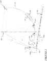
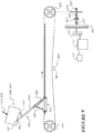
- the amusement ride comprises a carrier 100 for carrying at least one rider, a launch mechanism 200, and a tether 300.
- the carrier 100 is suspended to swing from a support 400.
- the carrier 100 is releasably coupled to the launch mechanism 200 via the tether 300, such that the carrier 100 is accelerated by the launch mechanism 200 to a release point 3 ( figure 2 ) where the tether 300 decouples from the carrier 100, thereby launching the carrier 100 on an upward trajectory in a first direction 150 along an arcuate path AP.
- the carrier swings back in an opposite second direction 160 along the arcuate path.
- the carrier continues to swing back and forth in swing arcs along the first direction 150 and the second direction 160 until the carrier comes to a stop at the lowest position of the arcuate path.
- the carrier 100 can swing back and forth about a pivot along a substantially two-dimensional arcuate path AP in the first and second directions, with a pendulum-like swinging motion.
- the carrier 100 can swing substantially freely about a pivot in three dimensions, i.e. along a partially spherical path.
- the carrier 100 may comprise controls to allow a rider to change the direction of the swinging arc such that the carrier 100 follows a partially spherical path, for example.
- the carrier controls may comprise a propeller and a rudder.
- the swinging movement of the carrier 100 is substantially solely along one or more arcuate paths.
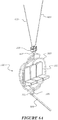
- FIGS. 6A and 6B show an exemplary embodiment of the carrier 100 arranged to support three riders.
- the carrier 100 comprises rider supports in the form of seats 101, a frame 103, a tether hook 105 and a carrier attachment 107.
- the carrier 100 may be arranged to support one rider. In further alternative embodiments, the carrier 100 may be arranged to support a plurality of riders, for example, two, four, five or more riders.
- the seats 101 are of known type and comprise harnesses of a known type (not illustrated).
- the seats 101 are fixed to the frame 103.
- the seats 101 may be rotatable relative to the frame 103.
- the carrier will be made of materials that are suitably weather resistant; for example, a galvanised steel frame and vinyl seats.
- the tether hook 105 is located at the bottom of the frame 103.
- the tether hook 105 is arranged to releasably engage with the tether 300.
- the tether hook 105 is arranged such that the open end of the hook is directed towards the back of the carrier 100 to provide passive releasable engagement with the tether 300.
- the tether hook 105 may comprise an actively controlled hook to releasably engage with the tether 300.
- the carrier attachment 107 is located at the top of the frame 103.
- the carrier attachment 107 is coupled to the suspension attachment 109.
- the carrier attachment 107 is rotatable relative to the suspension attachment 109. In alternative embodiments, the carrier attachment 107 may be fixed relative to the suspension attachment 109.
- the carrier is configured to support the rider(s) in a forward-facing upright seated orientation.
- the carrier may be configured to support the rider(s) in other orientations, such as forward- or rearward-facing prone orientations, either upwardly- or downwardly- facing for example.
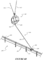
- FIGS 7A to 7C show an alternative exemplary embodiment carrier 100' for supporting a plurality of riders that can be used in the amusement ride. Unless described below, the features, functionality, and alternatives are the same as for the carrier 100 of figures 6A and 6B , and like reference numerals are used to indicate like parts, with the addition of a prime (').
- the carrier 100' comprises four rider supports in the form of seats 101', a frame comprising an upper frame member 103a' and a lower frame member 103b', a tether hook 105, and carrier attachments 107a', 107b'.
- the carrier 100' is suspended to swing from the support 400 by elongate suspension members 413a', 413b' 423a', 423b', in a similar manner described below for carrier 100 under the Support heading.
- the carrier 100' is suspended by two left side elongate suspension members 423a', 423b' and two right side elongate suspension members 413a', 413b' to inhibit rotation of the upper frame member 103a' relative to the elongate suspension members.
- Each seat 101' is rotatably coupled to the upper and lower frame members 103a', 103b' by upper and lower rotation couplings 104a', 104b'.
- One of the upper and lower rotation couplings may comprise a motor, such as a hydraulic or electric motor, to drive rotation of the seat 101' relative to the frame members 103a', 103b', and thereby relative to the suspension members 413a', 413b', 423a', 423b', about a respective axis SA that extends through the upper and lower rotation couplings 104a', 104b'.
- the other of the upper and lower rotation couplings may comprise a bearing, or may comprise a corresponding motor that is synchronised with the other motor so the rotational drive is provided to both the top and the bottom of each seat.
- the rider support seats 101' are configured to rotate relative to the upper and lower frame members 103a', 103b' and thereby relative to the elongate suspension member(s), at or near an end of each swing arc, so that rider(s) supported by the rider support(s) face forward throughout at least a major part of each swing arc, and advantageously throughout substantially the entirety of each swing arc.
- the riders may face forward (towards the right of the page) in the first swing direction until the carrier 100' reaches or is close to point 4.
- An accelerometer or other sensor coupled to the carrier 100' could determine when point 4 has been reached, and a controller that is in communication with the accelerometer/sensor will actuate the motors to cause the seats 101' to rotate through 180 degrees, so the riders then face forward (towards the left of the page) during the swing in the second direction. This will repeat at or near the top of that reverse swing so that the riders face forward (towards the right side of the page) during the swing in the first direction, and so on. The process may repeat until the carrier 100' stops swinging.
- the seats 101' could change direction before, at, or after the change in swing direction.
- the two outer rider supports 101' will be configured so that they only rotate outwardly, so prevent the legs of those two riders from contacting each other and interfering with the rotation of the seats.
- Power may be supplied to the motors via the elongate suspension members so that a separate power source does not need to be carried by the carrier 100'.
- the seat mechanisms may incorporate end stops to limit rotation of the seats. The direction of rotation of the seats will automatically reverse for each operation, based on sensors that determine the current seat position. Alternatively, the front and rear rider supports may rotate in one direction only, each time rotation occurs.
- the rider support rotation feature is described with reference to a carrier 100' that has four rider support seats 101', the rider support rotation feature could alternatively be implemented in a carrier having any suitable number of rider supports, such as 1, 2, 3, 4, or more rider supports. It could also be implemented in a carrier having rider support(s) that support rider(s) in different positions (e.g. prone positions) and/or different directions.
- the overall carrier 100, 100' may be configured to rotate relative to the suspension member(s).
- a motor could be provided between the carrier attachment 107 and the suspension attachment 109 in the carrier 100 of figure 6A , to cause the entire carrier to rotate at or near the end of each swing arc.
- the carrier 100 is suspended to swing from a support 400.
- the support comprises a support structure 400.
- the carrier 100 is arranged to swing from the support structure 400 in more than one direction along an arcuate path AP, the arcuate path having a lowest point in which the carrier is positioned closest to the elongate member 201 of the launch mechanism.
- Figure 1 shows an exemplary embodiment wherein the carrier 100 is suspended between two adjacent vertically-extending upright support towers 410, 420, one positioned on either lateral side of the arcuate path AP and the carrier 100.
- the carrier 100 is suspended from a single support tower.
- the single support tower may comprise a single vertically-extending upright support tower and a cantilevered extension from the top of the support tower, with the carrier suspended to swing from the cantilevered extension by one or more elongate suspension members.
- the support may comprise one or more elongate support members such as cable(s), rope(s), or line(s) for example, and the carrier 100 is suspended to swing from the elongate support member(s) by one or more elongate suspension members 413, 423 that hang from the elongate support member(s).
- the elongate support member(s) may comprise one or member(s) that extend(s) generally transversely to a longitudinal direction of the elongate suspension member(s).
- the elongate support member(s) may be suspended between support towers or may be suspended across a natural feature such as a gully.
- the support towers 410, 420 comprise cable pivots 411, 421 located at or adjacent the highest point of the towers.
- One elongate suspension member 413, 423 is shown on each side of the carrier 100.
- two or more elongate suspension members may extend from each cable pivot 411, 421 to the carrier 100.
- Elongate suspension members 413, 423 are rotatably engaged with the cable pivots 411, 421.
- the elongate suspension members 413, 423 are made from flexible members such as steel cable or another suitable weather resistant material.
- the elongate suspension members 413, 423 comprise a cable or a plurality of cables. In an alternative embodiment the elongate suspension members may be rigid members.
- the elongate suspension members 413, 423 are about 30m long. In alternative embodiments the elongate suspension members may be longer or shorter, for example 10m, 20m or 40m long.
- the distal ends of the elongate suspension members 413, 423 are coupled to the suspension attachment 109.
- the suspension attachment 109 connects the swing cables 413, 423 with the carrier 100 via the carrier attachment 107.
- the carrier 100 swings about the pivots at the upper ends of the elongate suspension members.
- Figure 2 shows the four sequential stages of launching the carrier 100:
- Figures 3-5 show detail of stages 1-3 respectively.
- the launch mechanism 200 is located outside of the arcuate path AP of the carrier.
- the launch mechanism is positioned substantially at ground level, and may be at least partially buried in the ground. Alternatively, the launch mechanism may be positioned above ground level.
- the launch mechanism may be positioned beneath the arcuate path AP, to the side of the arcuate path AP, or both beneath and to the side of the arcuate path AP.
- the launch mechanism 200 comprises a driven, elongate member 201 such as a launch cable, conveyor, or belt.
- the launch member could be any suitable material such as steel or ultra-high-molecular-weight polyethylene.
- the launch member 201 extends between two pulleys 203, 205.
- the pulley 205 is rotatably supported by suitable bearings 226, 227.
- the pulley 203 is rotatably supported by similar suitable bearings (not shown).
- the launch member 201 is releasably coupled to the carrier 100 by the tether 300 and is positioned beneath and/or to a side of the arcuate path.
- An energy source 211 is operatively connected to the launch member 201 to drive the launch member 201.
- the energy source 211 is controlled by motor controller 212.
- the launch mechanism is independent of the carrier 100 and independent of the elongate suspension members(s) 413, 423.
- the launch mechanism 200 comprises a flywheel 213 adapted to store energy and an energy source 211 to rotate the flywheel 213.
- the energy source 211 may be an internal combustion motor, diesel generator, electric motor, linear induction motor or any other suitable energy source.
- the energy source 211 is coupled to gearbox 215 via gearbox shaft 221.
- the gearbox is coupled to the flywheel 213 via the flywheel shaft 223.
- the energy source 211 drives the flywheel 213.
- the energy source 211 drives the flywheel 213 via a rotatable member such as a tyre drive.
- the flywheel shaft 223 is rotatably supported by bearings 225, 226, and 227.
- a first selective energy transfer mechanism 217 is operatively connected to the flywheel 213.
- the first selective energy transfer mechanism 217 is operable to transfer energy from the flywheel 213 to the launch member 201 to accelerate the carrier 100 along the portion of the arcuate path.
- the first selective energy transfer mechanism 217 is rotatably supported by bearings 225, 226.
- Activation of the first selective energy transfer mechanism 217 results in rotation of at least one of the pulleys 203, 205, to accelerate the carrier 100 along a portion of the arcuate path AP.
- first selective energy transfer mechanism 217 comprises a mechanical clutch.
- the clutch 217 is a hydraulically actuated fluid clutch. When hydraulic fluid is pressurised, the clutch will be engaged such that torque is transmitted from the flywheel to the respective carrier, via the clutch.
- the first selective energy transfer mechanism may comprise an epicyclic gearbox or a hydraulic motor.
- a linear induction motor or other suitable motor could be used instead of the flywheel and energy source arrangement.
- a pull-back winch 250 is releasably coupled to the carrier 100.
- the pull-back winch is positioned at a rear region of the launch mechanism 200, and may be mounted on a vertically extending upstand to position the pull-back winch higher than the launch mechanism.
- the pull-back winch 250 is arranged to pull the carrier 100 in the second direction 160 along the arcuate path to a pull-back/start position 1 that is higher than the lowest point of the arcuate path AP.
- the pull-back winch 250 comprises pull-back winch cable 251.
- Pull-back winch cable 251 is releasably coupled to carrier 100.
- the pull-back winch cable 251 can replace the tether-arresting member 311.
- the winch cable 251 may be connected to the tether 300.
- the tether hook 105 may comprise an actively controlled hook to releasably engage with the tether 300.
- the pull-back winch may be driven independently of the launch mechanism, such as via its own motor for example.
- the pull-back winch could be selectively driven by the flywheel 213, via a second selective energy transfer mechanism and reversing gearbox.
- the second selective energy transfer mechanism may comprise a mechanical clutch, an epicyclic gearbox, or a hydraulic motor.
- the tether 300 is arranged to releasably couple the carrier 100 to the launch mechanism 200 to accelerate the carrier 100 in a first direction through a portion of the arcuate path between an engagement position and a release position 3, and to decouple the carrier 100 from the launch system 200 at the release position to propel the carrier 100 on an upward trajectory on the arcuate path.
- the tether 300 may be any suitable length, such as 8m for example. In other embodiments, the tether may be 5m, 10m, 15m, or any other suitable length.
- a first end 301 of the tether 300 is coupled to the carrier 100.
- a second end 302 of the tether 300 is coupled to the launch mechanism 200.
- the first end 301 and second end 302 are connected by an intermediate member 303 via launch bogie 231.
- Launch bogie 231 is slideably engaged with launch rail 233.
- the tether 300 shown in figures 3-5 is releasably coupled to the carrier 100.
- the tether 300 is releasably coupled to the launch mechanism 200.
- the intermediate portion 303 of the tether is arranged to be decoupled. For example, about half of the intermediate portion 303 may remain connected to the carrier via the first end 301 following decoupling. The remaining part of the intermediate portion 303 may remain connected to the launch mechanism 200 via the second end 302 following decoupling.
- the tether 300 comprises a rigid member.
- the tether 300 comprises a flexible member.
- the tether can be made from any suitable weather resistant and strong material, such as steel for example.
- the tether may be made from a strong, lightweight material such as ultra-high-molecular-weight polyethylene rope for example.
- the tether is connected to a tether arresting member 311 arranged to restrict the movement of the tether following its release from the carrier 100.
- the tether arresting member 311 comprises a flexible member, such as a flexible cable.
- An end of the tether arresting member 311 is fastened to a fixed anchor 313.
- the fixed anchor is stationary relative to the ground.
- An opposite end of tether arresting member 311 is fastened to the tether 300, at or adjacent the first end 301 of the tether 300.
- An embodiment where the tether 300 comprises a flexible member may comprise a tether retraction device (not illustrated).
- the tether retraction device may be operatively connected to the launch mechanism 200.
- the tether retraction device may be arranged to retract the tether 300 when it is released from the carrier 100.
- the tether retraction device may be operatively connected to the carrier 100.
- the tether retraction device may be arranged to retract the tether 300 when it is released from the launch mechanism 200.
- a first tether retraction device (not illustrated) may be operatively connected to the carrier 100 and a second tether retraction device (not illustrated) may be operatively connected to the launch mechanism 200.
- the first and second tether retraction devices are arranged to retract respective portions of the tether when the intermediate portion 303 of the tether 300 is decoupled.
- Pull-back winch cable 251 and tether 300 are connected to the carrier 100. This may be accomplished before or after the rider or riders enter the carrier 100.
- the rider or riders board the carrier 100 via the loading platform 500.
- the platform 500 will initially be lowered down to ground level to enable the riders to enter the platform 500.
- the platform 500 is then raised to the position shown in figure 8 to enable the riders to enter the carrier 100.
- the carrier 100 is at the lowest point of the arcuate path AP when the riders enter the carrier 100.
- the rider or riders are secured into their seats using harnesses (not shown).
- a ride operator will be present on the platform to ensure that the riders are secured in the carrier 100 and to attach the pull-back winch cable 251 and the tether 300 to the carrier.
- the platform 500 is moved down and to the side of the arcuate path AP of the ride via hydraulically actuated arms 501, 502.
- a ride operator may control the ride from the platform 500.
- loading platform 500 could be used, such as a scissor lift or a rollaway platform for example.
- the pull-back winch 250 winds in the pull-back winch cable 251 in the second direction 160 to raise the carrier 100 to the rearward pull-back/start position 1, also shown in figure 3 .
- Acceleration begins with the release of the pull-back winch 250 at the start position. Either at the same time or slightly after, the launch bogie 231 is activated by engaging the first selective energy transfer mechanism 217 with the spinning flywheel 213.
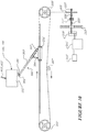
- Figure 4 shows the launch mechanism during the acceleration phase.
- the launch mechanism 200 is arranged to begin accelerating the carrier 100 when the carrier 100 is positioned at the engagement position along the arcuate path.
- the pull-back/start position shown in figures 2 and 3 may be the same as the engagement position.
- the launch mechanism 200 begins to accelerate the carrier 100 at the same time as the pull-back winch cable 251 is released.
- the pull-back/start position may be higher than the engagement position.
- the carrier could be pulled back to the maximum (vertical) extent of the tether.
- the carrier 100 initially accelerates under the influence of gravity for a short period of time along a portion of the arcuate path before the launch mechanism 200 begins to accelerate the carrier.
- the period of time could be any suitable time depending on the required speed of the launch bogie, such as about one second or any other suitable time.
- the tether 300 may be slack until the launch bogie 231 'catches up' with the carrier 100 and the launch mechanism accelerates the carrier 100. This may provide a smoother launch experience with less jarring for the riders.
- the engagement position is at an angle of between about 15° and about 45° in the second direction 160 relative to the lowest point of the arcuate path.
- the engagement position is at an angle of about 30° in the second direction 160 relative to the lowest point of the arcuate path.
- the launch bogie 231 pulls the carrier 100 via the tether 300 to the release position where the tether 300 decouples from the carrier 100 as a result of the fixed length tether arresting member 311 stopping movement of the tether and pulling the tether from the suitably angled hook on the carrier, to allow the carrier 100 to swing on the arcuate path AP to a maximum height.
- the carrier 100 will be travelling at maximum velocity at the point of release.
- Position 3 in figure 2 and figure 5 show the release position of the carrier where the tether 300 decouples from the carrier 100.
- the release position is at an angle of between about 15° and about 45° in the first direction 150 relative to the lowest point of the arcuate path AP.
- the release position is at an angle of about 30° in the first direction 150 relative to the lowest point of the arcuate path AP.
- the launch bogie 231 is brought to a stop via a braking means on the launch rail 233 or the pulley 205 (not shown).
- the bogie may be brought to a stop by means of tension on the tether 300 from the extended tether arresting member 311.
- the launch bogie 231 is then winched back to the start position by reversing the rotational direction of the pulleys 203, 205.
- the tether 300 is contained by the tether arresting member 311 and is retrieved by the operator for the following launch.
- the carrier will decelerate from the release point 3 to zero speed at the top point 4 of the swing.
- the carrier 100 is arranged to reach a maximum height when the direction of travel of the carrier 100 changes from the first direction 150 to the second direction 160, during the initial swing after being launched from the launch mechanism 200.
- the maximum height (position 4 of figure 2 ) is about 40m above the launch mechanism 200. In alternative embodiments, the maximum height may be more or less than 40m above the launch mechanism 200, for example about 10m, 20m, 30m, 50m or 60m above the launch mechanism 200.
- the maximum height is reached when the carrier 100 is at an angle of about 100° in the first direction 150 relative to the lowest point of the arcuate path. In alternative embodiments the maximum height is reached when the carrier 100 is at a different angle, such as an angle of about 30°, 40°, 50°, 60°, 70°, 80°, 90°, 100° or 120° in the first direction 150 relative to the lowest point of the arcuate path.
- the carrier swings back in a second direction 160 along the arcuate path. Where the highest point 4 is above the horizontal plane, the carrier will initially fall substantially vertically inside the arcuate path for a brief period until it meets the arcuate path. The carrier continues to swing back and forth along the first direction 150 and the second direction 160 until the carrier comes to a stop at the lowest position of the arcuate path. If a carrier 100' with the rotation feature is used, the rider support 101' of the carrier will rotate at or near the end of each swing arc to reverse the facing directions of the riders.
- a carrier brake (not shown) may be used to attenuate the swinging motion and bring the carrier 100 to a stop.
- the carrier brake may comprise an arresting cable that can be selectively raised above the launch rail to a height required to catch the hook under the carrier.
- a selective damping means may be provided on the elongate suspension members to attenuate the swinging motion.
- the next riders enter the loading platform 500 either while the carrier 100 is swinging or after it has come to a stop. Once the carrier 100 has come to a stop, the platform 500 will then be raised to the position shown in figure 7 to enable the riders to exit the carrier 100 and for the next riders to enter the carrier 100. The initial riders are released from their seats and the next riders are secured in their seats. The platform 500 then lowers the initial riders to the ground and the ride procedure is repeated.
- Table 1 outlines specifications relating to one exemplary embodiment of the ride. It will be appreciated that the specifications will change for differing embodiments. Table 1: Specifications of exemplary embodiment Length of elongate suspension members 413, 423 30 m Length of tether 300 8 m Angle of carrier 100 at pull-back/start position 1 30° Angle of carrier 100 at lowest point of arcuate path 0° Angle of carrier 100 at release position 3 -30° Mass of carrier 100 600 kg Mass of elongate suspension members 413, 423 0 kg Mass of tether 300 0 kg Mass of launch member 201 6.771 kg Height at highest point of the arcuate path 4 40 m Angle between tether 300 and suspension members 413, 423 at start position 1 120° Total length of launch mechanism 200 45 m Length of acceleration phase 30 m Bogie 231 braking distance 7.5 m Height of carrier 100 above launch mechanism 200 2.9 m Distance between bogie 231 position at start position 1 and bogie 231 position when carrier 100 is at lowest point of arcuate path
- the mass of the launch member 201 was estimated based on 10 mm diameter ultra-high-molecular-weight polyethylene rope with mass of 6.1 kg / 100 m and break strength of 105.4 kN.
- Table 2 outlines calculated properties relating to one exemplary embodiment of the ride based on the specifications outlined in table 1.
- Table 2 Calculated values for exemplary embodiment.
- Energy potential of carrier 100 at highest point 4 of arcuate path 235,440 J Velocity of carrier 100 at lowest point of arcuate path when swinging back from highest point 4 28.0 m/s Velocity of carrier 100 at release position 3 26.6 m/s Time to accelerate from start position 1 to release position 3 2.25 s Velocity of bogie 231 at release position 3 26.6 m/s Acceleration of bogie 231 between start position 1 and release position 3 (assuming linear acceleration) 11.8 m/s 2 Energy required to accelerate carrier 100 from rest 211,783 J
- the embodiments described herein provide configurations to elevate the swing carrier to the desired maximum swing height that are less time consuming than the prior art and do not require the construction or availability of an additional launch structure. It can be seen from the drawings and description that the embodiments described herein only require the carrier 100 to be moved back to a small height, while still enabling the carrier to be swung to a significant maximum swing height after release from the launch system.
- the launch arrangement is a high-speed arrangement whereby the swing carrier can be launched from at or near ground level at high velocity to rapidly attain the desired maximum swing height.
- a further advantage of the embodiments described herein is that the launch mechanism is independent of the carrier and the elongate suspension members, making the ride inherently safe. If the launch mechanism failed, the rider(s) would remain safely suspended in the carrier. After the initial launch by the launch system, the launch system is disconnected from the carrier (due to the tether being decoupled), and does not influence the swinging motion of the carrier.
- the carrier 100 is initially moved in the second direction 160 to the pull-back/start position.
- the launch system may be reversible to initially move the carrier rearwards in the second direction before launching the carrier in the first direction.
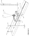
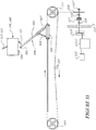
- Figures 9 to 11 show such a configuration including a push-back mechanism comprising the rigid tether 300' which can be used to both push the carrier 100, 100' rearwards in the second direction to a start position ( figure 9 ) and to accelerate ( figure 10 ) and launch ( figure 11 ) the 100 carrier in the first direction.
- a first end 301' of the rigid tether 300' is arranged to releasably couple to two parts of the carrier 100, 100'; a push-back engagement surface 102' ( figure 9 ) and the tether hook 105'.
- the second end 302' of the tether 300' is articulated to the launch bogie 231'.
- a position actuator 304' is provided between the launch bogie 231' and the tether 300'. In the form shown, the position actuator comprises a ram.
- the position actuator 304' enables the tether 300' to move from a relatively large angle (relative to the launch bogie 231') in the pushback position of figure 9 , to a relatively small angle in the lowest carrier position of figure 10 , to a relatively large angle in the release position of figure 11 .
- the position actuator 304' limits the maximum angle of the tether 300' relative to the launch bogie 231' so that the carrier 300' can detach from the tether 300' at the launch point.
- the position actuator may be biased toward its extended length, or may be controlled throughout the pushback and launch procedure.
- the pushback engagement surface 102' on the carrier 100, 100' comprises a step or shoulder that engages with the first end 301' of the tether.
- the pushback engagement surface could be any other suitable form.
- the first end 301' of the tether may comprise a cross member that is engageable with the pushback engagement surface 102' and with the engagement hook 105'.
- the launch mechanism is driven rearwardly so that the first end 301' of the tether pushes the carrier back to the start position shown in figure 9 .
- the launch mechanism is then driven forward rapidly so that the first end 301' of the tether slides along the underside of the carrier and engages the tether hook 105', to accelerate the carrier through the lowest swing position ( figure 10 ) to be released at the release position ( figure 11 ).
- the launch bogie 231' may remain at the position shown in figure 11 , or further towards the pulley 205' until the carrier 100, 100' has stopped swinging.
- the push back mechanism may comprise a push-back member that is separate from the tether 300' and independently driven, the push-back member arranged to push the carrier in the second direction along the arcuate path to the start position.
- the engagement position of the launch system may be at the lowest point of the arcuate path AP, and the carrier 100 may be launched from the position shown in figure 8 once the platform 500 is lowered, without initially pulling or pushing back the carrier to the start position.
- pulling or pushing the carrier back to the start position 1 is preferred, as that will enable the carrier to be swung to a greater maximum height, and may provide a smoother launch experience for the rider(s) if the carrier is initially released from the pull/push-back/start position before being engaged and launched by the launch system.
- the carrier 100 is described as swinging back and forward along the arcuate path AP after the carrier 100 has been launched.
- the carrier 100 may be steerable after the initial launch by the launch mechanism 200.
- the carrier may be provided with a controllable rudder or similar steering device to enable the rider(s) to control the direction of swinging of the carrier after the initial launch by the launch system 200.
- the rudder may, for example, be a tail rudder, and may be controlled by a steering input device such as a rider-operable control stick or other controller.
- Such a configuration may be particularly suited to a carrier that is suspended from a cantilevered support structure or from elongate support member(s) that is/are suspended, such as across a natural feature such as a gully for example.
- the carrier 100 may be provided with a rider-operable power source such as a propeller for example, to enable the rider to control the magnitude of swinging after the initial launch by the launch system 200.
Applications Claiming Priority (2)
| Application Number | Priority Date | Filing Date | Title |
|---|---|---|---|
| NZ72753616 | 2016-12-14 | ||
| PCT/NZ2017/050158 WO2018111121A1 (en) | 2016-12-14 | 2017-12-08 | Amusement ride |
Publications (3)
| Publication Number | Publication Date |
|---|---|
| EP3554661A1 EP3554661A1 (en) | 2019-10-23 |
| EP3554661A4 EP3554661A4 (en) | 2020-07-15 |
| EP3554661B1 true EP3554661B1 (en) | 2021-10-27 |
Family
ID=62559104
Family Applications (1)
| Application Number | Title | Priority Date | Filing Date |
|---|---|---|---|
| EP17880643.6A Active EP3554661B1 (en) | 2016-12-14 | 2017-12-08 | Amusement ride |
Country Status (8)
| Country | Link |
|---|---|
| US (1) | US10758830B2 (ko) |
| EP (1) | EP3554661B1 (ko) |
| JP (1) | JP7038715B2 (ko) |
| KR (1) | KR102526516B1 (ko) |
| CN (1) | CN110248710B (ko) |
| AU (1) | AU2017374060B2 (ko) |
| CA (1) | CA3048984A1 (ko) |
| WO (1) | WO2018111121A1 (ko) |
Families Citing this family (2)
| Publication number | Priority date | Publication date | Assignee | Title |
|---|---|---|---|---|
| CN114570031A (zh) * | 2020-09-18 | 2022-06-03 | 金华职业技术学院 | 一种基于非遗项目的游乐设施 |
| WO2023153942A1 (en) * | 2022-02-11 | 2023-08-17 | Skysurfer International Limited | Amusement ride |
Family Cites Families (22)
| Publication number | Priority date | Publication date | Assignee | Title |
|---|---|---|---|---|
| FR2653351A1 (fr) * | 1989-10-24 | 1991-04-26 | Poulouin Armand | Balancoire. |
| JP3045516B2 (ja) * | 1990-04-19 | 2000-05-29 | 株式会社アドイン研究所 | 動的推論パターン生成システム |
| US5267906A (en) | 1992-08-19 | 1993-12-07 | Sky Fun 1, Inc. | Amusement ride |
| US5527223A (en) | 1994-01-24 | 1996-06-18 | Kitchen; William J. | Swing type amusement ride |
| US5573465A (en) * | 1994-12-21 | 1996-11-12 | Kitchen; William J. | Pendulum damper |
| AU7536096A (en) | 1995-12-15 | 1997-06-19 | Fairmile Pty Ltd | An amusement ride |
| US5649866A (en) * | 1996-03-22 | 1997-07-22 | Balwanz; C. Grant | Amusement ride system |
| JP3882858B2 (ja) * | 1996-07-03 | 2007-02-21 | 株式会社セガ | 乗り物遊戯装置 |
| ATE274991T1 (de) * | 1996-10-06 | 2004-09-15 | Neil Horace Harrap | Motorbetriebene vergnügungsanlage |
| AU744294B2 (en) * | 1997-05-14 | 2002-02-21 | Fairmile Pty Ltd | Amusement ride (Case B) |
| AU744301B2 (en) | 1997-05-14 | 2002-02-21 | Fairmile Pty Ltd | Amusement ride (Case C) |
| US5931740A (en) * | 1997-07-15 | 1999-08-03 | Kitchen; William Joel | Module-type amusement ride |
| JP3045516U (ja) * | 1997-07-22 | 1998-02-03 | ヤマクニインターナショナル株式会社 | 娯楽用乗物 |
| US5810671A (en) * | 1997-08-13 | 1998-09-22 | Balwanz; C. Grant | Amusement ride system |
| US7066822B2 (en) * | 2000-11-10 | 2006-06-27 | Stat Cochron | Multidirectional amusement device |
| US6440002B1 (en) * | 2000-11-15 | 2002-08-27 | Skycoaster, Inc. | Top loading swing type amusement ride |
| US6561916B2 (en) * | 2001-02-01 | 2003-05-13 | Mark Kleimeyer | Rapid-winding winch for amusement ride |
| ITMI20022084A1 (it) * | 2002-10-02 | 2004-04-03 | Zamperla Antonio Spa | Apparato per il divertimento. |
| US6875118B1 (en) * | 2004-05-13 | 2005-04-05 | S & S Worldwide, Inc. | Pneumatically actuated swing ride |
| CN101991952A (zh) * | 2009-08-10 | 2011-03-30 | 刘吉彬 | 一种电动悬挂摆体装置 |
| CN102019086B (zh) * | 2009-09-21 | 2014-07-30 | 刘吉彬 | 一种动力秋千装置 |
| US20140261051A1 (en) * | 2013-03-15 | 2014-09-18 | William J. Kitchen | Amusement ride |
-
2017
- 2017-12-08 JP JP2019532938A patent/JP7038715B2/ja active Active
- 2017-12-08 EP EP17880643.6A patent/EP3554661B1/en active Active
- 2017-12-08 CN CN201780085654.0A patent/CN110248710B/zh active Active
- 2017-12-08 WO PCT/NZ2017/050158 patent/WO2018111121A1/en unknown
- 2017-12-08 KR KR1020197020102A patent/KR102526516B1/ko active IP Right Grant
- 2017-12-08 US US16/467,369 patent/US10758830B2/en active Active
- 2017-12-08 AU AU2017374060A patent/AU2017374060B2/en active Active
- 2017-12-08 CA CA3048984A patent/CA3048984A1/en active Pending
Also Published As
| Publication number | Publication date |
|---|---|
| AU2017374060B2 (en) | 2018-08-30 |
| JP2020501732A (ja) | 2020-01-23 |
| US10758830B2 (en) | 2020-09-01 |
| WO2018111121A1 (en) | 2018-06-21 |
| EP3554661A1 (en) | 2019-10-23 |
| CN110248710A (zh) | 2019-09-17 |
| US20200094153A1 (en) | 2020-03-26 |
| KR20190095360A (ko) | 2019-08-14 |
| KR102526516B1 (ko) | 2023-04-26 |
| CN110248710B (zh) | 2021-03-19 |
| CA3048984A1 (en) | 2018-06-21 |
| EP3554661A4 (en) | 2020-07-15 |
| JP7038715B2 (ja) | 2022-03-18 |
| AU2017374060A1 (en) | 2018-07-12 |
Similar Documents
| Publication | Publication Date | Title |
|---|---|---|
| US20160114252A1 (en) | Suspended Amusement Ride System | |
| EP3554661B1 (en) | Amusement ride | |
| JP6517798B2 (ja) | 移動可能な軌道セクションを有するアミューズメント装置 | |
| EP3229931B1 (en) | High angle tethered slide with freefall drop and variable radius swing | |
| US9272223B2 (en) | Swing amusement ride system | |
| CN1116844A (zh) | 带有防摇摆装置的集装箱船卸货机 | |
| US7666103B2 (en) | Amusement ride | |
| CN107002910B (zh) | 海洋管道铺设系统中的端头配件操作 | |
| US20190358551A1 (en) | High Angle Tethered Slide with Freefall Drop and Variable Radius Swing | |
| US6342017B1 (en) | Amusement ride with enhanced ride control | |
| EP0934106A1 (en) | Swing type amusement ride with pendulum damper | |
| WO2014141195A1 (en) | Amusement ride | |
| AU744294B2 (en) | Amusement ride (Case B) | |
| EP1590056B1 (en) | Amusement ride | |
| AU744299B2 (en) | Amusement ride - Case A | |
| CN201670343U (zh) | 风电设备安装用摆臂式起重驳船 | |
| EP2896441A1 (en) | Swing amusement ride system | |
| CN214042671U (zh) | 一种模拟太空行走的设备 | |
| US10717015B2 (en) | High angle tethered slide with freefall drop and variable radius swing | |
| CN112509411A (zh) | 一种模拟太空行走的设备 | |
| NZ548749A (en) | Recreational apparatus |
Legal Events
| Date | Code | Title | Description |
|---|---|---|---|
| STAA | Information on the status of an ep patent application or granted ep patent |
Free format text: STATUS: THE INTERNATIONAL PUBLICATION HAS BEEN MADE |
|
| PUAI | Public reference made under article 153(3) epc to a published international application that has entered the european phase |
Free format text: ORIGINAL CODE: 0009012 |
|
| STAA | Information on the status of an ep patent application or granted ep patent |
Free format text: STATUS: REQUEST FOR EXAMINATION WAS MADE |
|
| 17P | Request for examination filed |
Effective date: 20190628 |
|
| AK | Designated contracting states |
Kind code of ref document: A1 Designated state(s): AL AT BE BG CH CY CZ DE DK EE ES FI FR GB GR HR HU IE IS IT LI LT LU LV MC MK MT NL NO PL PT RO RS SE SI SK SM TR |
|
| AX | Request for extension of the european patent |
Extension state: BA ME |
|
| RAP1 | Party data changed (applicant data changed or rights of an application transferred) |
Owner name: SKYSURFER INTERNATIONAL LIMITED |
|
| DAV | Request for validation of the european patent (deleted) | ||
| DAX | Request for extension of the european patent (deleted) | ||
| A4 | Supplementary search report drawn up and despatched |
Effective date: 20200617 |
|
| RIC1 | Information provided on ipc code assigned before grant |
Ipc: A63G 31/08 20060101ALI20200610BHEP Ipc: A63G 9/16 20060101AFI20200610BHEP |
|
| GRAP | Despatch of communication of intention to grant a patent |
Free format text: ORIGINAL CODE: EPIDOSNIGR1 |
|
| STAA | Information on the status of an ep patent application or granted ep patent |
Free format text: STATUS: GRANT OF PATENT IS INTENDED |
|
| INTG | Intention to grant announced |
Effective date: 20210527 |
|
| GRAS | Grant fee paid |
Free format text: ORIGINAL CODE: EPIDOSNIGR3 |
|
| GRAA | (expected) grant |
Free format text: ORIGINAL CODE: 0009210 |
|
| STAA | Information on the status of an ep patent application or granted ep patent |
Free format text: STATUS: THE PATENT HAS BEEN GRANTED |
|
| AK | Designated contracting states |
Kind code of ref document: B1 Designated state(s): AL AT BE BG CH CY CZ DE DK EE ES FI FR GB GR HR HU IE IS IT LI LT LU LV MC MK MT NL NO PL PT RO RS SE SI SK SM TR |
|
| REG | Reference to a national code |
Ref country code: GB Ref legal event code: FG4D |
|
| REG | Reference to a national code |
Ref country code: CH Ref legal event code: EP |
|
| REG | Reference to a national code |
Ref country code: DE Ref legal event code: R096 Ref document number: 602017048503 Country of ref document: DE |
|
| REG | Reference to a national code |
Ref country code: AT Ref legal event code: REF Ref document number: 1441299 Country of ref document: AT Kind code of ref document: T Effective date: 20211115 |
|
| REG | Reference to a national code |
Ref country code: IE Ref legal event code: FG4D |
|
| REG | Reference to a national code |
Ref country code: LT Ref legal event code: MG9D |
|
| REG | Reference to a national code |
Ref country code: NL Ref legal event code: MP Effective date: 20211027 |
|
| REG | Reference to a national code |
Ref country code: AT Ref legal event code: MK05 Ref document number: 1441299 Country of ref document: AT Kind code of ref document: T Effective date: 20211027 |
|
| PG25 | Lapsed in a contracting state [announced via postgrant information from national office to epo] |
Ref country code: RS Free format text: LAPSE BECAUSE OF FAILURE TO SUBMIT A TRANSLATION OF THE DESCRIPTION OR TO PAY THE FEE WITHIN THE PRESCRIBED TIME-LIMIT Effective date: 20211027 Ref country code: LT Free format text: LAPSE BECAUSE OF FAILURE TO SUBMIT A TRANSLATION OF THE DESCRIPTION OR TO PAY THE FEE WITHIN THE PRESCRIBED TIME-LIMIT Effective date: 20211027 Ref country code: FI Free format text: LAPSE BECAUSE OF FAILURE TO SUBMIT A TRANSLATION OF THE DESCRIPTION OR TO PAY THE FEE WITHIN THE PRESCRIBED TIME-LIMIT Effective date: 20211027 Ref country code: BG Free format text: LAPSE BECAUSE OF FAILURE TO SUBMIT A TRANSLATION OF THE DESCRIPTION OR TO PAY THE FEE WITHIN THE PRESCRIBED TIME-LIMIT Effective date: 20220127 Ref country code: AT Free format text: LAPSE BECAUSE OF FAILURE TO SUBMIT A TRANSLATION OF THE DESCRIPTION OR TO PAY THE FEE WITHIN THE PRESCRIBED TIME-LIMIT Effective date: 20211027 |
|
| PG25 | Lapsed in a contracting state [announced via postgrant information from national office to epo] |
Ref country code: IS Free format text: LAPSE BECAUSE OF FAILURE TO SUBMIT A TRANSLATION OF THE DESCRIPTION OR TO PAY THE FEE WITHIN THE PRESCRIBED TIME-LIMIT Effective date: 20220227 Ref country code: SE Free format text: LAPSE BECAUSE OF FAILURE TO SUBMIT A TRANSLATION OF THE DESCRIPTION OR TO PAY THE FEE WITHIN THE PRESCRIBED TIME-LIMIT Effective date: 20211027 Ref country code: PT Free format text: LAPSE BECAUSE OF FAILURE TO SUBMIT A TRANSLATION OF THE DESCRIPTION OR TO PAY THE FEE WITHIN THE PRESCRIBED TIME-LIMIT Effective date: 20220228 Ref country code: PL Free format text: LAPSE BECAUSE OF FAILURE TO SUBMIT A TRANSLATION OF THE DESCRIPTION OR TO PAY THE FEE WITHIN THE PRESCRIBED TIME-LIMIT Effective date: 20211027 Ref country code: NO Free format text: LAPSE BECAUSE OF FAILURE TO SUBMIT A TRANSLATION OF THE DESCRIPTION OR TO PAY THE FEE WITHIN THE PRESCRIBED TIME-LIMIT Effective date: 20220127 Ref country code: NL Free format text: LAPSE BECAUSE OF FAILURE TO SUBMIT A TRANSLATION OF THE DESCRIPTION OR TO PAY THE FEE WITHIN THE PRESCRIBED TIME-LIMIT Effective date: 20211027 Ref country code: LV Free format text: LAPSE BECAUSE OF FAILURE TO SUBMIT A TRANSLATION OF THE DESCRIPTION OR TO PAY THE FEE WITHIN THE PRESCRIBED TIME-LIMIT Effective date: 20211027 Ref country code: HR Free format text: LAPSE BECAUSE OF FAILURE TO SUBMIT A TRANSLATION OF THE DESCRIPTION OR TO PAY THE FEE WITHIN THE PRESCRIBED TIME-LIMIT Effective date: 20211027 Ref country code: GR Free format text: LAPSE BECAUSE OF FAILURE TO SUBMIT A TRANSLATION OF THE DESCRIPTION OR TO PAY THE FEE WITHIN THE PRESCRIBED TIME-LIMIT Effective date: 20220128 Ref country code: ES Free format text: LAPSE BECAUSE OF FAILURE TO SUBMIT A TRANSLATION OF THE DESCRIPTION OR TO PAY THE FEE WITHIN THE PRESCRIBED TIME-LIMIT Effective date: 20211027 |
|
| REG | Reference to a national code |
Ref country code: DE Ref legal event code: R097 Ref document number: 602017048503 Country of ref document: DE |
|
| PG25 | Lapsed in a contracting state [announced via postgrant information from national office to epo] |
Ref country code: SM Free format text: LAPSE BECAUSE OF FAILURE TO SUBMIT A TRANSLATION OF THE DESCRIPTION OR TO PAY THE FEE WITHIN THE PRESCRIBED TIME-LIMIT Effective date: 20211027 Ref country code: SK Free format text: LAPSE BECAUSE OF FAILURE TO SUBMIT A TRANSLATION OF THE DESCRIPTION OR TO PAY THE FEE WITHIN THE PRESCRIBED TIME-LIMIT Effective date: 20211027 Ref country code: RO Free format text: LAPSE BECAUSE OF FAILURE TO SUBMIT A TRANSLATION OF THE DESCRIPTION OR TO PAY THE FEE WITHIN THE PRESCRIBED TIME-LIMIT Effective date: 20211027 Ref country code: MC Free format text: LAPSE BECAUSE OF FAILURE TO SUBMIT A TRANSLATION OF THE DESCRIPTION OR TO PAY THE FEE WITHIN THE PRESCRIBED TIME-LIMIT Effective date: 20211027 Ref country code: EE Free format text: LAPSE BECAUSE OF FAILURE TO SUBMIT A TRANSLATION OF THE DESCRIPTION OR TO PAY THE FEE WITHIN THE PRESCRIBED TIME-LIMIT Effective date: 20211027 Ref country code: DK Free format text: LAPSE BECAUSE OF FAILURE TO SUBMIT A TRANSLATION OF THE DESCRIPTION OR TO PAY THE FEE WITHIN THE PRESCRIBED TIME-LIMIT Effective date: 20211027 Ref country code: CZ Free format text: LAPSE BECAUSE OF FAILURE TO SUBMIT A TRANSLATION OF THE DESCRIPTION OR TO PAY THE FEE WITHIN THE PRESCRIBED TIME-LIMIT Effective date: 20211027 |
|
| REG | Reference to a national code |
Ref country code: CH Ref legal event code: PL |
|
| PLBE | No opposition filed within time limit |
Free format text: ORIGINAL CODE: 0009261 |
|
| STAA | Information on the status of an ep patent application or granted ep patent |
Free format text: STATUS: NO OPPOSITION FILED WITHIN TIME LIMIT |
|
| REG | Reference to a national code |
Ref country code: BE Ref legal event code: MM Effective date: 20211231 |
|
| 26N | No opposition filed |
Effective date: 20220728 |
|
| PG25 | Lapsed in a contracting state [announced via postgrant information from national office to epo] |
Ref country code: LU Free format text: LAPSE BECAUSE OF NON-PAYMENT OF DUE FEES Effective date: 20211208 Ref country code: AL Free format text: LAPSE BECAUSE OF FAILURE TO SUBMIT A TRANSLATION OF THE DESCRIPTION OR TO PAY THE FEE WITHIN THE PRESCRIBED TIME-LIMIT Effective date: 20211027 |
|
| PG25 | Lapsed in a contracting state [announced via postgrant information from national office to epo] |
Ref country code: SI Free format text: LAPSE BECAUSE OF FAILURE TO SUBMIT A TRANSLATION OF THE DESCRIPTION OR TO PAY THE FEE WITHIN THE PRESCRIBED TIME-LIMIT Effective date: 20211027 Ref country code: BE Free format text: LAPSE BECAUSE OF NON-PAYMENT OF DUE FEES Effective date: 20211231 |
|
| PG25 | Lapsed in a contracting state [announced via postgrant information from national office to epo] |
Ref country code: LI Free format text: LAPSE BECAUSE OF NON-PAYMENT OF DUE FEES Effective date: 20211231 Ref country code: CH Free format text: LAPSE BECAUSE OF NON-PAYMENT OF DUE FEES Effective date: 20211231 |
|
| PGFP | Annual fee paid to national office [announced via postgrant information from national office to epo] |
Ref country code: FR Payment date: 20221227 Year of fee payment: 6 |
|
| PG25 | Lapsed in a contracting state [announced via postgrant information from national office to epo] |
Ref country code: IT Free format text: LAPSE BECAUSE OF FAILURE TO SUBMIT A TRANSLATION OF THE DESCRIPTION OR TO PAY THE FEE WITHIN THE PRESCRIBED TIME-LIMIT Effective date: 20211027 |
|
| PGFP | Annual fee paid to national office [announced via postgrant information from national office to epo] |
Ref country code: DE Payment date: 20221223 Year of fee payment: 6 |
|
| PG25 | Lapsed in a contracting state [announced via postgrant information from national office to epo] |
Ref country code: CY Free format text: LAPSE BECAUSE OF FAILURE TO SUBMIT A TRANSLATION OF THE DESCRIPTION OR TO PAY THE FEE WITHIN THE PRESCRIBED TIME-LIMIT Effective date: 20211027 |
|
| P01 | Opt-out of the competence of the unified patent court (upc) registered |
Effective date: 20230530 |
|
| PG25 | Lapsed in a contracting state [announced via postgrant information from national office to epo] |
Ref country code: HU Free format text: LAPSE BECAUSE OF FAILURE TO SUBMIT A TRANSLATION OF THE DESCRIPTION OR TO PAY THE FEE WITHIN THE PRESCRIBED TIME-LIMIT; INVALID AB INITIO Effective date: 20171208 |
|
| PGFP | Annual fee paid to national office [announced via postgrant information from national office to epo] |
Ref country code: GB Payment date: 20231206 Year of fee payment: 7 |
|
| PGFP | Annual fee paid to national office [announced via postgrant information from national office to epo] |
Ref country code: IE Payment date: 20231206 Year of fee payment: 7 |
|
| PG25 | Lapsed in a contracting state [announced via postgrant information from national office to epo] |
Ref country code: MK Free format text: LAPSE BECAUSE OF FAILURE TO SUBMIT A TRANSLATION OF THE DESCRIPTION OR TO PAY THE FEE WITHIN THE PRESCRIBED TIME-LIMIT Effective date: 20211027 |