EP3554591B1 - Dispositif de sécurité à boîtier pliable et à activation de déclenchement - Google Patents
Dispositif de sécurité à boîtier pliable et à activation de déclenchement Download PDFInfo
- Publication number
- EP3554591B1 EP3554591B1 EP17822921.7A EP17822921A EP3554591B1 EP 3554591 B1 EP3554591 B1 EP 3554591B1 EP 17822921 A EP17822921 A EP 17822921A EP 3554591 B1 EP3554591 B1 EP 3554591B1
- Authority
- EP
- European Patent Office
- Prior art keywords
- safety device
- spring
- drug delivery
- rotating cam
- needle
- Prior art date
- Legal status (The legal status is an assumption and is not a legal conclusion. Google has not performed a legal analysis and makes no representation as to the accuracy of the status listed.)
- Active
Links
Images


Classifications
-
- A—HUMAN NECESSITIES
- A61—MEDICAL OR VETERINARY SCIENCE; HYGIENE
- A61M—DEVICES FOR INTRODUCING MEDIA INTO, OR ONTO, THE BODY; DEVICES FOR TRANSDUCING BODY MEDIA OR FOR TAKING MEDIA FROM THE BODY; DEVICES FOR PRODUCING OR ENDING SLEEP OR STUPOR
- A61M5/00—Devices for bringing media into the body in a subcutaneous, intra-vascular or intramuscular way; Accessories therefor, e.g. filling or cleaning devices, arm-rests
- A61M5/178—Syringes
- A61M5/31—Details
- A61M5/32—Needles; Details of needles pertaining to their connection with syringe or hub; Accessories for bringing the needle into, or holding the needle on, the body; Devices for protection of needles
- A61M5/3205—Apparatus for removing or disposing of used needles or syringes, e.g. containers; Means for protection against accidental injuries from used needles
- A61M5/321—Means for protection against accidental injuries by used needles
- A61M5/322—Retractable needles, i.e. disconnected from and withdrawn into the syringe barrel by the piston
- A61M5/3221—Constructional features thereof, e.g. to improve manipulation or functioning
-
- A—HUMAN NECESSITIES
- A61—MEDICAL OR VETERINARY SCIENCE; HYGIENE
- A61M—DEVICES FOR INTRODUCING MEDIA INTO, OR ONTO, THE BODY; DEVICES FOR TRANSDUCING BODY MEDIA OR FOR TAKING MEDIA FROM THE BODY; DEVICES FOR PRODUCING OR ENDING SLEEP OR STUPOR
- A61M5/00—Devices for bringing media into the body in a subcutaneous, intra-vascular or intramuscular way; Accessories therefor, e.g. filling or cleaning devices, arm-rests
- A61M5/178—Syringes
- A61M5/31—Details
- A61M5/32—Needles; Details of needles pertaining to their connection with syringe or hub; Accessories for bringing the needle into, or holding the needle on, the body; Devices for protection of needles
- A61M5/3202—Devices for protection of the needle before use, e.g. caps
- A61M5/3204—Needle cap remover, i.e. devices to dislodge protection cover from needle or needle hub, e.g. deshielding devices
-
- A—HUMAN NECESSITIES
- A61—MEDICAL OR VETERINARY SCIENCE; HYGIENE
- A61M—DEVICES FOR INTRODUCING MEDIA INTO, OR ONTO, THE BODY; DEVICES FOR TRANSDUCING BODY MEDIA OR FOR TAKING MEDIA FROM THE BODY; DEVICES FOR PRODUCING OR ENDING SLEEP OR STUPOR
- A61M5/00—Devices for bringing media into the body in a subcutaneous, intra-vascular or intramuscular way; Accessories therefor, e.g. filling or cleaning devices, arm-rests
- A61M5/178—Syringes
- A61M5/31—Details
- A61M5/32—Needles; Details of needles pertaining to their connection with syringe or hub; Accessories for bringing the needle into, or holding the needle on, the body; Devices for protection of needles
- A61M5/3205—Apparatus for removing or disposing of used needles or syringes, e.g. containers; Means for protection against accidental injuries from used needles
- A61M5/321—Means for protection against accidental injuries by used needles
- A61M5/3213—Caps placed axially onto the needle, e.g. equipped with finger protection guards
-
- A—HUMAN NECESSITIES
- A61—MEDICAL OR VETERINARY SCIENCE; HYGIENE
- A61M—DEVICES FOR INTRODUCING MEDIA INTO, OR ONTO, THE BODY; DEVICES FOR TRANSDUCING BODY MEDIA OR FOR TAKING MEDIA FROM THE BODY; DEVICES FOR PRODUCING OR ENDING SLEEP OR STUPOR
- A61M5/00—Devices for bringing media into the body in a subcutaneous, intra-vascular or intramuscular way; Accessories therefor, e.g. filling or cleaning devices, arm-rests
- A61M5/178—Syringes
- A61M5/31—Details
- A61M5/32—Needles; Details of needles pertaining to their connection with syringe or hub; Accessories for bringing the needle into, or holding the needle on, the body; Devices for protection of needles
- A61M5/3205—Apparatus for removing or disposing of used needles or syringes, e.g. containers; Means for protection against accidental injuries from used needles
- A61M5/321—Means for protection against accidental injuries by used needles
- A61M5/322—Retractable needles, i.e. disconnected from and withdrawn into the syringe barrel by the piston
- A61M5/3232—Semi-automatic needle retraction, i.e. in which triggering of the needle retraction requires a deliberate action by the user, e.g. manual release of spring-biased retraction means
-
- A—HUMAN NECESSITIES
- A61—MEDICAL OR VETERINARY SCIENCE; HYGIENE
- A61M—DEVICES FOR INTRODUCING MEDIA INTO, OR ONTO, THE BODY; DEVICES FOR TRANSDUCING BODY MEDIA OR FOR TAKING MEDIA FROM THE BODY; DEVICES FOR PRODUCING OR ENDING SLEEP OR STUPOR
- A61M5/00—Devices for bringing media into the body in a subcutaneous, intra-vascular or intramuscular way; Accessories therefor, e.g. filling or cleaning devices, arm-rests
- A61M5/178—Syringes
- A61M5/31—Details
- A61M5/32—Needles; Details of needles pertaining to their connection with syringe or hub; Accessories for bringing the needle into, or holding the needle on, the body; Devices for protection of needles
- A61M5/3205—Apparatus for removing or disposing of used needles or syringes, e.g. containers; Means for protection against accidental injuries from used needles
- A61M5/321—Means for protection against accidental injuries by used needles
- A61M5/3243—Means for protection against accidental injuries by used needles being axially-extensible, e.g. protective sleeves coaxially slidable on the syringe barrel
- A61M5/3245—Constructional features thereof, e.g. to improve manipulation or functioning
-
- A—HUMAN NECESSITIES
- A61—MEDICAL OR VETERINARY SCIENCE; HYGIENE
- A61M—DEVICES FOR INTRODUCING MEDIA INTO, OR ONTO, THE BODY; DEVICES FOR TRANSDUCING BODY MEDIA OR FOR TAKING MEDIA FROM THE BODY; DEVICES FOR PRODUCING OR ENDING SLEEP OR STUPOR
- A61M5/00—Devices for bringing media into the body in a subcutaneous, intra-vascular or intramuscular way; Accessories therefor, e.g. filling or cleaning devices, arm-rests
- A61M5/178—Syringes
- A61M5/31—Details
- A61M5/32—Needles; Details of needles pertaining to their connection with syringe or hub; Accessories for bringing the needle into, or holding the needle on, the body; Devices for protection of needles
- A61M5/3205—Apparatus for removing or disposing of used needles or syringes, e.g. containers; Means for protection against accidental injuries from used needles
- A61M5/321—Means for protection against accidental injuries by used needles
- A61M5/3243—Means for protection against accidental injuries by used needles being axially-extensible, e.g. protective sleeves coaxially slidable on the syringe barrel
- A61M5/326—Fully automatic sleeve extension, i.e. in which triggering of the sleeve does not require a deliberate action by the user
-
- A—HUMAN NECESSITIES
- A61—MEDICAL OR VETERINARY SCIENCE; HYGIENE
- A61M—DEVICES FOR INTRODUCING MEDIA INTO, OR ONTO, THE BODY; DEVICES FOR TRANSDUCING BODY MEDIA OR FOR TAKING MEDIA FROM THE BODY; DEVICES FOR PRODUCING OR ENDING SLEEP OR STUPOR
- A61M5/00—Devices for bringing media into the body in a subcutaneous, intra-vascular or intramuscular way; Accessories therefor, e.g. filling or cleaning devices, arm-rests
- A61M5/178—Syringes
- A61M5/31—Details
- A61M5/32—Needles; Details of needles pertaining to their connection with syringe or hub; Accessories for bringing the needle into, or holding the needle on, the body; Devices for protection of needles
- A61M5/3205—Apparatus for removing or disposing of used needles or syringes, e.g. containers; Means for protection against accidental injuries from used needles
- A61M5/321—Means for protection against accidental injuries by used needles
- A61M5/3243—Means for protection against accidental injuries by used needles being axially-extensible, e.g. protective sleeves coaxially slidable on the syringe barrel
- A61M5/3273—Means for protection against accidental injuries by used needles being axially-extensible, e.g. protective sleeves coaxially slidable on the syringe barrel freely sliding on needle shaft without connection to syringe or needle
-
- A—HUMAN NECESSITIES
- A61—MEDICAL OR VETERINARY SCIENCE; HYGIENE
- A61M—DEVICES FOR INTRODUCING MEDIA INTO, OR ONTO, THE BODY; DEVICES FOR TRANSDUCING BODY MEDIA OR FOR TAKING MEDIA FROM THE BODY; DEVICES FOR PRODUCING OR ENDING SLEEP OR STUPOR
- A61M5/00—Devices for bringing media into the body in a subcutaneous, intra-vascular or intramuscular way; Accessories therefor, e.g. filling or cleaning devices, arm-rests
- A61M5/178—Syringes
- A61M5/31—Details
- A61M5/32—Needles; Details of needles pertaining to their connection with syringe or hub; Accessories for bringing the needle into, or holding the needle on, the body; Devices for protection of needles
- A61M5/34—Constructions for connecting the needle, e.g. to syringe nozzle or needle hub
-
- A—HUMAN NECESSITIES
- A61—MEDICAL OR VETERINARY SCIENCE; HYGIENE
- A61M—DEVICES FOR INTRODUCING MEDIA INTO, OR ONTO, THE BODY; DEVICES FOR TRANSDUCING BODY MEDIA OR FOR TAKING MEDIA FROM THE BODY; DEVICES FOR PRODUCING OR ENDING SLEEP OR STUPOR
- A61M5/00—Devices for bringing media into the body in a subcutaneous, intra-vascular or intramuscular way; Accessories therefor, e.g. filling or cleaning devices, arm-rests
- A61M5/178—Syringes
- A61M5/31—Details
- A61M5/32—Needles; Details of needles pertaining to their connection with syringe or hub; Accessories for bringing the needle into, or holding the needle on, the body; Devices for protection of needles
- A61M5/3205—Apparatus for removing or disposing of used needles or syringes, e.g. containers; Means for protection against accidental injuries from used needles
- A61M5/321—Means for protection against accidental injuries by used needles
- A61M5/3243—Means for protection against accidental injuries by used needles being axially-extensible, e.g. protective sleeves coaxially slidable on the syringe barrel
- A61M5/3245—Constructional features thereof, e.g. to improve manipulation or functioning
- A61M2005/3247—Means to impede repositioning of protection sleeve from needle covering to needle uncovering position
Definitions
- the present disclosure relates generally to a drug delivery safety device having a passive trigger activation system, i.e. , structure for activation of the trigger which is engaged upon use of the drug delivery device to provide post-injection needle shielding without additional intervention by the user.
- a passive trigger activation system i.e. , structure for activation of the trigger which is engaged upon use of the drug delivery device to provide post-injection needle shielding without additional intervention by the user.
- US 2004/010227 A1 discloses a spring launched needle safety clip of a hypodermic needle assembly.
- a first aspect pertains to a drug delivery safety device comprising a body attached to a needle hub.
- the body encloses a rotating cam engaged in a slot through a sidewall of the body.
- the slot comprises three segments: a proximal angled lead ramp, a ledge at the distal end of the angled lead ramp for seating the rotating cam, and an axial slot portion distal to the ledge.
- the needle hub includes a needle cannula which is surrounded by a flexible housing.
- the flexible housing connects the body to a lock clip near the distal end of the needle cannula such that the needle cannula is substantially covered by the flexible housing but the distal tip of the cannula is exposed.
- the passive shielding system is activated by a trigger mechanism comprising a first spring which connects the rotating cam to the lock clip and a second spring in the body extending from the rotating cam proximally toward the needle hub.
- the first spring biases the lock clip distally and the second spring biases the rotating cam distally.
- the force applied to the rotating cam by the second spring is sufficient to seat the rotating cam on the ledge of the slot and to maintain its seated position prior to use of the cannula for injection.
- the first spring may surround the needle cannula within the flexible housing.
- the lock clip may be housed in a cap which is attached to the flexible housing, the cap including an aperture to permit the cannula to pass therethrough.
- a proximally-directed force greater than the distally-directed force of the second spring is applied to the lock clip.
- the first spring is compressed, and the flexible housing retracts proximally.
- the proximal force also moves the lock clip proximally along the shaft of the cannula.
- This proximal force is typically applied when the exposed tip of the needle cannula is inserted into the skin of a patient to the desired depth for administering an injection.
- the proximal force overcomes the biasing force of the second spring to move the rotating cam in a proximal direction, off of the ledge and down the angled lead ramp.
- the angled surface of the angled lead ramp causes the rotating cam to rotate as it moves to the proximal end of the angled lead ramp.
- the first spring decompresses, allowing the second spring to again apply sufficient distal force to the rotated rotating cam to move it distally along the axial slot portion. This force moves the lock clip in a distal direction past the distal tip of the needle cannula to cover the distal tip.
- the needle hub of the drug delivery safety device may be attached to the barrel of a syringe.
- the flexible housing may be a spring coil, a butterfly spring, a zig-zag coil or a rolled-sheet coil. In one or more embodiments, the flexible housing may have slack when in the pre-injection extended position that permits further extension of the flexible housing post-injection to permit the lock clip to cover the distal tip of the needle cannula.
- the first and second springs may be composed of a single spring that is fed through the rotating cam.
- the lock clip may be a hook clip which contacts the shaft of the needle cannula near the distal end and slides proximally along its length as the needle cannula is inserted into the patient's skin and the first spring is compressed.
- the hook clip moves distally along the needle cannula and past the distal tip so that the hook portion of the hook clip covers the distal tip.
- the lock clip may be comprised of two pieces, one on each side of the needle cannula and each having a contact point with the needle cannula surface.
- This lock clip functions in the passive drug delivery safety device as discussed above with respect to the hook clip, except that when the two-piece clip moves distally past the distal tip of the needle cannula, the two pieces close together to cover the distal tip.
- the drug delivery safety device may further comprise a removable sleeve which fits over the body to prevent triggering of the trigger mechanism.
- a removable sleeve which fits over the body to prevent triggering of the trigger mechanism. This feature allows the device to be used to fill a syringe prior to injection without activating the passive shielding system.
- the removable sleeve is removed after filling of the syringe so that the passive shielding system becomes available for triggering when used to administer an injection.
- the anti-triggering sleeve fits over the body and includes an interior surface having a protrusion (e.g. , a ridge) which engages the axial slot portion of the slot, thereby preventing movement and rotation of the rotating cam.
- the anti-triggering system may further comprise a cap which is a removable fill cap covering the exposed tip of the needle cannula. Prior to filling, both the anti-triggering cap and the fill cap may be present on the device. To fill a syringe, the fill cap is removed. Because of the presence of the anti-triggering sleeve, a syringe can be filled multiple times without triggering the passive safety mechanism. If it is desired to transport the filled syringe or delay injection, the fill cap can optionally be re-attached. When it is desired to administer an injection, the anti-triggering sleeve is removed (with the fill cap, if present) to permit movement and rotation of the rotating cam.
- a second aspect pertains to a drug delivery safety device comprising a trigger mechanism connecting a needle hub to a lock clip near the distal end of the needle cannula.
- a flexible housing surrounds the needle cannula and connects the needle hub to the lock clip such that the needle cannula is substantially covered by the flexible housing but the distal tip of the cannula is exposed.
- the passive shielding system is activated by a trigger mechanism comprising a spring which connects the needle hub to the lock clip.
- the device also includes a body which engages the needle hub. The body has an inner cavity with proximal and distal ends, and a Y-clip disposed in the inner cavity.
- First and second arms of the Y-clip are held open by engagement with first and second pockets at the distal end of the inner cavity as well as by distal force exerted by the spring which biases the first and second arms toward the "splayed" or “open” position.
- the first and second arms of the Y-clip have angled surfaces so that when they are moved toward each other (inwardly or toward a "closed” position) an axial vector force is created.
- the Y-clip may include at least two protrusions which function as travel stops to prevent the Y-clip from leaving the body, thus setting the distance of distal travel of the lock clip.
- the spring may surround the needle cannula within the flexible housing.
- the lock clip may be housed in a cap which is attached to the flexible housing, the cap including an aperture to permit the cannula to pass therethrough.
- a proximally-directed force applied to the lock clip compresses the spring distally. Compression of the spring retracts the flexible housing in a proximal direction and also moves the lock clip proximally along the needle cannula to expose more of the distal end of the needle cannula. This proximal force is typically applied when the exposed tip of the needle cannula is inserted into the skin of a patient to the desired depth for administering an injection.
- the proximal force of the compressed spring creates slack in the flexible housing, which allows the Y-clip to move proximally within the body to release the first and second arms from the first and second pockets of the body, and allows the first and second arms to move inwardly toward each other, creating an axial vector force.
- the spring decompresses, and the axial vector force moves the lock clip distally past the distal tip of the needle cannula to cover the distal tip.
- the needle hub of the drug delivery safety device may be attached to the barrel of a syringe.
- the flexible housing may be a spring coil, a butterfly spring, a zig-zag coil or a rolled-sheet coil. In one or more embodiments, the flexible housing may have slack when in the pre-injection extended position that permits further extension of the flexible housing post-injection to permit the lock clip to cover the distal tip of the needle cannula.
- the lock clip may be a hook clip which contacts the needle cannula near the distal end and slides proximally along its length as the needle cannula is inserted into the patient's skin, compressing the spring. During the passive shielding portion of the procedure (after removal of the needle cannula from the patient's skin), the hook clip moves distally along the needle cannula and past the distal tip so that the hook covers the distal tip.
- the lock clip may be comprised of two pieces, one on each side of the needle cannula and each having a contact point with the shaft of the needle cannula.
- This lock clip functions in the passive drug delivery safety device as discussed above with respect to the hook clip, except that when the two-piece clip moves distally past the distal tip of the needle cannula, the two pieces close together to cover the distal tip.
- the drug delivery safety device may further comprise a removable anti-triggering cap which fits over the body and prevents triggering of the trigger mechanism. This feature allows the device to be used to fill a syringe prior to injection without activating the passive shielding system.
- the removable anti-triggering cap is removed after filling of the syringe so that the passive shielding system becomes available for triggering when used to administer an injection.
- the cap may have an outer wall which fits over the exterior wall of the body and an interior wall which is positioned between the first and second legs of the Y-clip when the cap is placed over the body. The position of the interior wall between the first and second arms keeps the arms “splayed” or “open” even when the spring is compressed, thus preventing release of the first and second arms from the first and second pockets when proximal force is applied.
- the anti-triggering system may further comprise a second cap which is a removable fill cap covering the exposed tip of the needle cannula.
- a second cap which is a removable fill cap covering the exposed tip of the needle cannula.
- both the anti-triggering cap and the fill cap Prior to filling, both the anti-triggering cap and the fill cap are present on the device. To fill a syringe, the fill cap is removed. Because of the presence of the anti-triggering cap, the syringe can be filled multiple times without triggering the passive safety mechanism. If it is desired to transport the filled syringe or delay injection, the fill cap can optionally be re-attached. When it is desired to administer an injection, the anti-triggering cap is removed (with the fill cap, if present) to permit movement of the arms of the Y-clip.
- a third aspect pertains to a drug delivery safety device comprising a needle hub with a needle cannula, and at least two flexible arms axially adjacent to the needle cannula connecting a trigger housing near the distal end of the cannula to the needle hub.
- the trigger housing includes an aperture in the distal wall which permits the needle cannula to pass therethrough.
- a trigger mechanism inside the trigger housing is comprised of a spring connecting the trigger housing to the flexible arms, and a double leaf spring lock clip.
- the lock clip is positioned near the distal end of the needle cannula, such that the tip of the needle cannula is exposed through an aperture in the lock clip.
- a first leaf of the lock clip removably engages the flexible arms and a second leaf of the lock clip engages the trigger housing.
- the second leaf of the lock clip includes a distal needle tip cover which, prior to triggering, is in contact with the needle cannula near its distal end, thus keeping the needle tip cover out of alignment with the apertures of the trigger housing and the lock clip.
- the spring biases the trigger housing and the lock clip in the distal direction, preventing proximal movement of the trigger housing and the lock clip along the shaft of the needle cannula, and maintaining engagement of the first leaf of the lock clip with the flexible arms.
- the needle hub of the drug delivery safety device may be attached to the barrel of a syringe by attachment of the needle hub to the collar of the syringe barrel.
- the spring may be a spring coil or a leaf spring.
- the trigger housing may be configured to fit over an end-cap connecting the at least two flexible arms.
- the end-cap includes an aperture aligned with the apertures of the trigger housing and the lock clip, permitting the needle cannula to pass therethrough.
- the end-cap may be integrally molded with the at least two flexible arms.
- the spring may surround the end-cap and, prior to use, be biased against the distal interior wall of the trigger housing, thereby forcing the trigger housing and lock clip distally to maintain engagement of the first leaf of the lock clip with the at least two flexible arms.
- the first leaf of the lock clip may removably engage the at least two arms by removable engagement with the end-cap, e.g. , by means of a proximal hook on the first leaf which engages a shelf on the end-cap.
- a distally-directed force applied to the trigger housing compresses the spring, moving the trigger housing and the lock clip proximally toward the at least two flexible arms. This movement allows the first leaf of the lock clip to disengage from the end-cap. Tension released from the first leaf of the lock clip allows it to flex to an unloaded state, thus maintaining the disengaged position during continued proximal movement of the trigger housing. After disengagement, the needle can be inserted to the desired depth with the at least two flexible arms flexing outward. Upon removal of the needle cannula from the skin, post-injection, the spring fully decompresses and the trigger housing moves distally along the shaft of the needle cannula past the distal tip.
- the needle tip cap of the second leaf of the lock clip is released from contact with the needle cannula and flexes into the needle tip covering position.
- the force required to move the trigger housing and release the first leaf of the lock clip is less than the force to flex the two or more flexible arms so that the passive shielding mechanism is triggered within a short distance during injection
- the drug safety delivery device may further comprise structure for preventing triggering of the passive safety mechanism prior to administering the injection. This feature allows the device to be used to fill a syringe prior to injection without activating the passive shielding system.
- the anti-triggering structure is removed or disabled after filling of the syringe so that the passive shielding system becomes available for triggering during injection.
- the anti-triggering structure may comprise a removable cap or sleeve which includes a rib to hold the first leaf of the lock clip in the engaged position and constrain proximal motion of the trigger housing during fill. Subsequent to filling the syringe, the cap is removed to allow proximal movement of the trigger housing and passive shielding upon injection.
- the anti-triggering component includes a removable fill cap which covers the needle cannula exposed at the distal end of the removable cap or sleeve prior to filling the syringe.
- the anti-triggering component may comprise a bracket and pull-pin.
- the bracket e.g. , a "U" bracket
- the pull-pin facilitates removal of the bracket by pulling it to the side. This permits proximal movement of the trigger housing and passive shielding upon injection.
- This embodiment may also comprise a removable fill cap to cover the exposed needle cannula prior to filling the syringe.
- the fill cap may include a slot to accommodate fitting over the side pull-pin.
- the user first removes the fill cap to fill the syringe which, due to the anti-triggering constraints of the removable sleeve or cap, can be done multiple times.
- the second component of the anti-triggering mechanism e.g. , sleeve/cap or bracket/pull pin
- the fill cap can be re-applied until such time as injection is desired. In this case, the fill cap and second component are both removed prior to injection to allow triggering.
- the needle tip may be exposed through the distal end of the housing of the locking mechanism or the housing may cover the needle tip provided that the needle tip is exposed through the distal end of the lock clip.
- proximal refers to a direction toward the needle hub or toward the syringe when the drug safety delivery device is attached to a syringe.
- distal distal-directed and related terms with respect to the drug safety delivery device refer to a direction toward the needle tip or toward the patient's skin when the device is in use for administering an injection.
- safety devices for passive shielding the distal tip of a needle cannula after it is used for injection.
- the safety devices include a collapsible or flexible structure directly or indirectly connecting the needle hub to a locking clip positioned at the distal end of the needle cannula. Initially, prior to use, the needle tip is exposed through the locking clip.
- the collapsible or flexible structure is longitudinally oriented between the needle hub and the locking clip, and surrounds, or runs adjacent to, the cannula. Prior to use of the safety device there is stored energy in the form of tension on the safety device which prevents the safety device from triggering and keeps the needle tip exposed for use.
- the safety device When the needle tip is inserted into the skin of the patient, the stored energy in the system is released and the safety device is activated or triggered. However, once activation occurs, the safety device does not shield the needle as long as the needle remains in the skin. This permits the user to continue to insert the needle to the desired depth. Only upon removal of the needle from the skin does the activated safety device automatically advance the locking clip forward to cover the tip of the needle, thereby automatically and passively preventing needle stick injury as soon as the injection is completed.
- the safety devices include additional components which allow for filling of a syringe, without triggering the passive safety mechanism, prior to injection.
- these features can be achieved by several embodiments of the safety device.
- these several embodiments provide the advantage of requiring less force against the patient's skin during injection to trigger the passive safety mechanism.
- the various aspects and embodiments also provide a passive mechanism for shielding a needle which activates during injection over a shorter stroke distance.
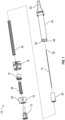
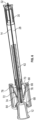
- the rotating force trigger drug delivery safety device 10 comprises a needle hub 12 for attachment of drug delivery safety device 10 to a syringe, needle hub 12 having an attached needle cannula 14.
- a body 16 which engages needle hub 12, encloses a rotating cam 18.
- Rotating cam 18 engages body 16 through a slot in a sidewall 20 of body 16.
- the slot comprises three segments: a proximal angled lead ramp 22, a ledge 24 at the distal end of the angled lead ramp for seating the rotating cam, and an axial slot portion 26 distal to the ledge.
- needle cannula 14 is surrounded by a flexible housing 28 which connects rotating cam 18 to a lock clip 30 near the distal end of needle cannula 14 such that needle cannula 14 is substantially covered by the flexible housing but distal tip 32 of the cannula is exposed.
- the passive shielding system includes a trigger mechanism comprising a first spring 34 which connects rotating cam 18 to lock clip 30 and a second spring 36 in body 16 extending from rotating cam 18 proximally toward needle hub 12.
- First spring 34 biases lock clip 30 distally and second spring 36 biases rotating cam 18 distally.
- Lock clip 30 may be housed in a cap 38 which is attached to flexible housing 28.
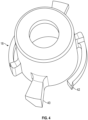
- FIG. 4 An embodiment of rotating cam 18, configured for engagement with two slots opposite each other in body 16, is illustrated in more detail in Fig. 4 .
- Tabs 40 are configured to engage the slots in body 16.
- Wings 42 may be present on the periphery of rotating cam 18 for engagement with threads or channels on the interior wall of body 16 to facilitate smooth rotation in only one direction. Wings 42 start in an un-flexed state and, as rotating cam 18 rotates, wings 42 may ride over ribs on the inner surface of housing 16. The ribs and head of wings 42 have biased ramps such that a ratchet is created. This prevents tabs 40 from reengaging with ledge 24 of body 16 during distal travel.
- Tabs 40 may be cylindrical to allow for a line contact area with angled lead ramp 22 or they may have a matching helix to increase the contact area, reducing binding and resistance to motion.
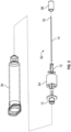
- the anti-triggering component is a removable anti-triggering sleeve 44 which is hollow and configured to fit over drug safety delivery device 10 to engage body 16.
- An interior surface 46 of anti-triggering sleeve 44 includes a rib 48 configured to engage axial slot portion 26 and prevent rotation of rotating cam 18 when sleeve 44 is in place.
- Removable fill cap 50 covers the distal opening of anti-triggering sleeve 44 to prevent access to needle cannula 14 until the syringe is to be filled, at which time it is removed and rib 48 of sleeve 44 engaged in axial slot portion 26 prevents rotation of rotating cam 18 during fill.
- removable anti-triggering sleeve 44 is removed from drug delivery safety device 10. This anti-triggering configuration also allows for a very low force trigger at time of use, because the anti-trigger rib prevents triggering during shipping and shelf storage.
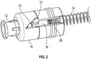
- This drug delivery safety device 60 comprises a spring 62 connecting a needle hub 12 to a lock clip 30 near the distal end of the needle cannula 14. Needle hub 12 provides attachment of drug delivery safety device 60 to a syringe 94.
- a flexible housing 28 surrounds needle cannula 14 and connects Y-clip 72 to lock clip 30 such that needle cannula 14 is substantially covered by flexible housing 28 but the distal tip 32 of cannula 14 is exposed.
- Body 64 has an inner cavity 66 with proximal end 68 and distal end 70, and a Y-clip 72 disposed in inner cavity 66.
- First arm 74 and second arms 76 of Y-clip 72 are held open by engagement, respectively, with first pocket 78 and second pocket 80 at the distal end of the inner cavity and by force of spring 62 which biases the first and second arms toward the "splayed" or "open” position.
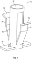
- First and second arms 74, 76 of Y-clip 72 have angled surfaces 73, as shown in more detail in Fig. 7 .
- Lock clip 30 is housed in a cap 86 which is attached to flexible housing 28.
- Y-clip 72 is shown in more detail in Fig. 7 , including a sleeve 82 which fittingly engages needle hub 12 and includes aperture 84 which permits needle cannula 14 to pass therethrough.
- Travel stop 85 is a protruding member that engages with a lip on the inside of body 64 to limit distal travel of the Y-clip.
- Fig. 8 illustrates an anti-triggering component for use with. drug delivery safety device 60.
- Removable anti-triggering cap 86 comprises an outer wall 88 configured to fit over the outside of body 64.
- Anti-triggering cap 86 further comprises an interior wall 90 which sits between first and second arms 74, 76 of Y-clip 72 when anti-triggering cap 86 is in place. Interior wall 90 thus prevents release of first and second arms 74, 76 from first and second pockets 78, 80.
- Removable fill cap 92 covers the distal end of drug delivery safety device 60 to prevent access to needle cannula 14 until syringe 94 is to be filled, at which time it is removed and Y-clip 72 prevents movement of first and second arms 74, 76 during fill. When syringe 94 is filled and an injection is to be administered, anti-triggering cap 86 is removed from drug delivery safety device 60.
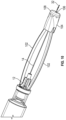
- This drug delivery safety device 100 comprises a needle hub 12 with a needle cannula 14 for attachment to a syringe 94, and at least two flexible arms 102 axially adjacent to needle cannula 14 to connect a trigger housing 104 to needle hub 12.
- trigger housing 104 includes an aperture 106 in a distal wall 108 thereof, through which distal tip 32 of cannula 14 is exposed.
- a trigger mechanism inside trigger housing 104 is comprised of a spring 110 (shown in Fig. 11 ) connecting trigger housing 104 to flexible arms 102.
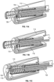
- the trigger mechanism also includes a double leaf spring lock clip 112, shown in detail in Fig. 12 , having a first leaf 114 which removably engages flexible arms 102 and a second leaf 116 which engages trigger housing 104 to retain lock clip 112 within trigger housing 104.
- Second leaf 116 includes a distal needle tip cover 118 which, prior to triggering ( Fig. 11A ), is in contact with the needle cannula to keep needle tip cover 118 out of alignment with aperture 106 of trigger housing 104 and aperture 120 of lock clip 112.
- An end-cap 122 connects the distal ends of the two flexible arms.
- Trigger housing 104 fits over end-cap 122.
- spring 110 indirectly connects lock clip 112 to flexible arms 102 via engagement with end-cap 122.
- the end-cap includes an aperture 124 aligned with aperture 106 of trigger housing 104 and aperture 120 of lock clip 112.
- Fig. 9 also shows an anti-triggering component for use with drug delivery safety device 100.
- Removable anti-triggering sleeve 126 is hollow and configured to fit over drug safety delivery device 100 to engage needle hub 12.
- Anti-triggering sleeve 126 includes a rib configured to hold down first leaf 114 of lock clip 112.
- Removable anti-triggering sleeve 126 constrains motion of trigger housing 104 when in place.
- Removable fill cap 128 covers the distal opening of anti-triggering sleeve 126 to prevent access to needle cannula 14 until the syringe is to be filled, at which time it is removed and the rib of anti-triggering sleeve 126 prevents disengagement of first leaf 114 from flexible arms 102.
- removable sleeve 126 is removed from drug delivery safety device 100.
Landscapes
- Health & Medical Sciences (AREA)
- Engineering & Computer Science (AREA)
- Life Sciences & Earth Sciences (AREA)
- Animal Behavior & Ethology (AREA)
- Anesthesiology (AREA)
- Biomedical Technology (AREA)
- Heart & Thoracic Surgery (AREA)
- Hematology (AREA)
- Veterinary Medicine (AREA)
- Vascular Medicine (AREA)
- General Health & Medical Sciences (AREA)
- Public Health (AREA)
- Environmental & Geological Engineering (AREA)
- Infusion, Injection, And Reservoir Apparatuses (AREA)
- Orthopedics, Nursing, And Contraception (AREA)
- Professional, Industrial, Or Sporting Protective Garments (AREA)
- Containers And Plastic Fillers For Packaging (AREA)
Claims (11)
- Dispositif de sécurité d'administration de médicament comprenant :un raccord d'aiguille (12) comprenant une canule (14) ayant une pointe distale (32) ; et un mécanisme de déclenchement ;caractérisé parun corps (16) configuré pour s'engager avec le raccord d'aiguille (12), le corps (16) comprenant une came rotative (18) engagée dans au moins une fente à travers une paroi latérale (20) du corps (16), la fente comprenant une rampe de guidage inclinée proximale (22), un rebord (24) pour placer la came rotative (18) distal par rapport à la rampe de guidage (22), et une partie de fente axiale distale par rapport au rebord ;un boîtier flexible (28) entourant la canule d'aiguille (14) reliant la came rotative (18) à un clip de verrouillage (30) au niveau d'une extrémité distale de la canule d'aiguille (14) de sorte que la pointe distale (32) de la canule (14) soit exposée distalement au clip de verrouillage (30) ;le mécanisme de déclenchement comprenant un premier ressort (34) reliant la came rotative (18) au clip de verrouillage (30) et un deuxième ressort (36) s'étendant de la came rotative (18) de manière proximale vers le raccord d'aiguille (12), où le deuxième ressort (36) applique une force suffisante à la came rotative (18) dans une direction distale pour placer la came rotative (18) sur le rebord (24) ;dans lequel une force dirigée de manière proximale appliquée au clip de verrouillage (30) qui est supérieure à la force distale du deuxième ressort (36) comprime le premier ressort (34), relâche la tension sur le boîtier flexible (28) et déplace la came rotative (18) dans une direction proximale hors du rebord (24) et le long de la rampe de guidage inclinée (22), provoquant ainsi la rotation de la came rotative (18) ; etdans lequel une diminution subséquente de la force proximale appliquée au clip de verrouillage (30) décomprime le premier ressort (34) et le deuxième ressort (36) déplace la came rotative (18) de manière distale dans la partie de fente axiale de sorte que le clip de verrouillage (30) se déplace dans une direction distale pour couvrir la pointe distale (32) de la canule (14).
- Dispositif de sécurité d'administration de médicament de la revendication 1, dans lequel le clip de verrouillage (30) est reçu dans un capuchon fixé au boîtier flexible (28), le capuchon comprenant une ouverture (84) pour permettre à la canule (14) de passer à travers celle-ci.
- Dispositif de sécurité d'administration de médicament de la revendication 2, dans lequel le boîtier flexible (28) est sélectionné dans le groupe constitué d'un ressort hélicoïdal, d'un ressort papillon, d'un tube en film, d'un filament, d'une bobine en zigzag, de manchons télescopiques et d'une bobine de tôle laminée.
- Dispositif de sécurité d'administration de médicament de la revendication 2, dans lequel le boîtier flexible (28) est lâche lorsque le dispositif de sécurité d'administration de médicament est dans une configuration de pré-injection.
- Dispositif de sécurité d'administration de médicament de l'une des revendications 1 à 4, dans lequel les premier et deuxième ressorts (34, 36) comprennent un ressort unique acheminé à travers la came rotative (18).
- Dispositif de sécurité d'administration de médicament de l'une des revendications 1 à 5, dans lequel l'au moins une fente représente deux fentes sur des côtés opposés du corps (16).
- Dispositif de sécurité d'administration de médicament de l'une des revendications 1 à 6, dans lequel le clip de verrouillage (30) est un clip à crochet ou un clip en deux pièces.
- Dispositif de sécurité d'administration de médicament de l'une des revendications 1 à 7, qui est fixé à une seringue via le raccord d'aiguille (12).
- Dispositif de sécurité d'administration de médicament de l'une des revendications 1 à 8, comprenant en outre un manchon anti-déclenchement amovible (82) qui s'ajuste sur le corps (16) et empêche le déclenchement du mécanisme de déclenchement, le manchon comprenant :un corps creux ayant une surface intérieure (46) ; etune saillie sur la surface intérieure (46) qui s'engage avec la partie de fente axiale (26) du corps, empêchant ainsi le mouvement et la rotation de la came rotative (18).
- Dispositif de sécurité d'administration de médicament de la revendication 9, dans lequel la saillie est une nervure (48).
- Dispositif de sécurité d'administration de médicament de la revendication 9, comprenant en outre un capuchon de remplissage (92) couvrant la pointe distale exposée (32) de la canule (14).
Priority Applications (2)
| Application Number | Priority Date | Filing Date | Title |
|---|---|---|---|
| EP25158567.5A EP4534125A3 (fr) | 2016-12-13 | 2017-12-12 | Dispositif de sécurité à boîtier pliable et activation de déclenchement |
| EP20151736.4A EP3695866B1 (fr) | 2016-12-13 | 2017-12-12 | Dispositif de sécurité à boîtier démontable et activation de déclenchement |
Applications Claiming Priority (3)
| Application Number | Priority Date | Filing Date | Title |
|---|---|---|---|
| US201662433297P | 2016-12-13 | 2016-12-13 | |
| US15/837,469 US10814073B2 (en) | 2016-12-13 | 2017-12-11 | Safety device with collapsible housing and trigger activation |
| PCT/US2017/065679 WO2018111791A2 (fr) | 2016-12-13 | 2017-12-12 | Dispositif de sécurité à boîtier pliable et à activation de déclenchement |
Related Child Applications (3)
| Application Number | Title | Priority Date | Filing Date |
|---|---|---|---|
| EP25158567.5A Division EP4534125A3 (fr) | 2016-12-13 | 2017-12-12 | Dispositif de sécurité à boîtier pliable et activation de déclenchement |
| EP20151736.4A Division EP3695866B1 (fr) | 2016-12-13 | 2017-12-12 | Dispositif de sécurité à boîtier démontable et activation de déclenchement |
| EP20151736.4A Division-Into EP3695866B1 (fr) | 2016-12-13 | 2017-12-12 | Dispositif de sécurité à boîtier démontable et activation de déclenchement |
Publications (3)
| Publication Number | Publication Date |
|---|---|
| EP3554591A2 EP3554591A2 (fr) | 2019-10-23 |
| EP3554591C0 EP3554591C0 (fr) | 2023-06-14 |
| EP3554591B1 true EP3554591B1 (fr) | 2023-06-14 |
Family
ID=62488074
Family Applications (3)
| Application Number | Title | Priority Date | Filing Date |
|---|---|---|---|
| EP17822921.7A Active EP3554591B1 (fr) | 2016-12-13 | 2017-12-12 | Dispositif de sécurité à boîtier pliable et à activation de déclenchement |
| EP25158567.5A Pending EP4534125A3 (fr) | 2016-12-13 | 2017-12-12 | Dispositif de sécurité à boîtier pliable et activation de déclenchement |
| EP20151736.4A Active EP3695866B1 (fr) | 2016-12-13 | 2017-12-12 | Dispositif de sécurité à boîtier démontable et activation de déclenchement |
Family Applications After (2)
| Application Number | Title | Priority Date | Filing Date |
|---|---|---|---|
| EP25158567.5A Pending EP4534125A3 (fr) | 2016-12-13 | 2017-12-12 | Dispositif de sécurité à boîtier pliable et activation de déclenchement |
| EP20151736.4A Active EP3695866B1 (fr) | 2016-12-13 | 2017-12-12 | Dispositif de sécurité à boîtier démontable et activation de déclenchement |
Country Status (8)
| Country | Link |
|---|---|
| US (3) | US10814073B2 (fr) |
| EP (3) | EP3554591B1 (fr) |
| JP (3) | JP7010947B2 (fr) |
| CN (3) | CN113926024B (fr) |
| AU (3) | AU2017375768B2 (fr) |
| CA (1) | CA3044537C (fr) |
| ES (1) | ES2952769T3 (fr) |
| WO (1) | WO2018111791A2 (fr) |
Families Citing this family (7)
| Publication number | Priority date | Publication date | Assignee | Title |
|---|---|---|---|---|
| US10814073B2 (en) * | 2016-12-13 | 2020-10-27 | Becton, Dickinson And Company | Safety device with collapsible housing and trigger activation |
| NL2022351B1 (en) | 2019-01-07 | 2020-08-13 | Vitestro Holding B V | Contact sensor positioning system, cannula insertion system and method to position a contact sensor |
| NL2022350B1 (en) * | 2019-01-07 | 2020-08-13 | Vitestro Holding B V | Cannula insertion system |
| CN111282094B (zh) * | 2020-03-05 | 2020-11-10 | 苏州恒瑞宏远医疗科技有限公司 | 自动注射装置及其使用方法 |
| CN113018589B (zh) * | 2021-02-06 | 2024-02-06 | 焦作市妇幼保健院(焦作市妇女儿童医院) | 一种防刺伤一次性注射器 |
| USD998788S1 (en) * | 2021-04-08 | 2023-09-12 | Medivena Sp. Z O.O. | Safety mechanism for hypodermic needle |
| USD1077211S1 (en) * | 2021-04-08 | 2025-05-27 | MediVena Sp. z.o.o. | Safety mechanism for hypodermic needle |
Family Cites Families (69)
| Publication number | Priority date | Publication date | Assignee | Title |
|---|---|---|---|---|
| ES2020280B3 (es) | 1986-11-19 | 1991-08-01 | Sterimatic Holdings Ltd | Mejoras en o relacionadas con jeringas. |
| US4795432A (en) | 1987-02-19 | 1989-01-03 | Karczmer Claude M | Shield assembly for hypodermic injection devices |
| US4804371A (en) * | 1987-05-06 | 1989-02-14 | Vaillancourt Vincent L | Post-injection needle sheath |
| US4887998A (en) * | 1987-12-14 | 1989-12-19 | Martin Catherine L | Hypodermic needle guard |
| US4950250A (en) | 1988-02-23 | 1990-08-21 | Habley Medical Technology Corporation | Collapsible needle cover |
| US5013305A (en) * | 1988-06-29 | 1991-05-07 | Opie Eric A | Needle safety system and method |
| US5176655A (en) | 1990-11-08 | 1993-01-05 | Mbo Laboratories, Inc. | Disposable medical needle and catheter placement assembly having full safety enclosure means |
| WO1994000172A1 (fr) * | 1992-06-22 | 1994-01-06 | Wong Henry C C | Dispositif de protection automatique pour une aiguille hypodermique a usage unique |
| US5295972A (en) * | 1992-08-04 | 1994-03-22 | Metatech Corporation | Hypodermic syringe with protective cap |
| US5984899A (en) | 1993-02-11 | 1999-11-16 | Beech Medical Products, Inc. | Needle protector device having a lockable protective cover which is unlockable during actuation |
| US5882337A (en) | 1995-06-07 | 1999-03-16 | Johnson & Johnson Medical, Inc. | Tip protection device |
| US5591138A (en) | 1995-08-10 | 1997-01-07 | Vaillancourt; Vincent L. | Protected needle assembly |
| US5688241A (en) | 1996-04-15 | 1997-11-18 | Asbaghi; Hooman Ali | Automatic non-reusable needle guard |
| FR2801795B1 (fr) | 1999-12-07 | 2002-07-05 | Plastef Investissements | Dispositif de support de securite pour une seringue et ensemble d'un tel dispositif et d'une seringue |
| US7361159B2 (en) | 2001-03-02 | 2008-04-22 | Covidien Ag | Passive safety shield |
| US6623458B2 (en) | 2001-09-26 | 2003-09-23 | B. Braun Melsungen, Ag | Spring launched needle safety clip |
| US7354422B2 (en) | 2001-09-26 | 2008-04-08 | B. Braun Melsungen Ag | Spring launched needle safety clip |
| US20040030294A1 (en) * | 2001-11-28 | 2004-02-12 | Mahurkar Sakharam D. | Retractable needle single use safety syringe |
| US6926700B2 (en) | 2002-03-19 | 2005-08-09 | Becton, Dickinson And Company | Needle assembly |
| US6884237B2 (en) | 2002-12-10 | 2005-04-26 | Inviro Medical Devices, Inc. | Position guide for a needle guard |
| US6926697B2 (en) | 2003-05-13 | 2005-08-09 | Robert Malenchek | Adaptor for converting a non-safety syringe into a safety syringe |
| US20050075609A1 (en) * | 2003-10-01 | 2005-04-07 | Latona Patrick C. | Protective needle clips |
| BRPI0506836B8 (pt) | 2004-01-28 | 2021-06-22 | Specialized Health Products Inc | aparelho de proteção de agulha médica |
| EP1762262A3 (fr) * | 2004-02-13 | 2007-03-21 | Smiths Medical ASD, Inc. | Protection du point d'aiguille |
| US7513888B2 (en) | 2004-02-17 | 2009-04-07 | Smiths Medical Asd, Inc. | Needle guards |
| US7651476B2 (en) * | 2004-09-28 | 2010-01-26 | B. Braun Medical Inc. | Protective clips |
| US8827961B2 (en) | 2005-02-03 | 2014-09-09 | West Pharmaceutical Services, Inc. | Safety needle |
| US20070078403A1 (en) | 2005-08-25 | 2007-04-05 | Don Millerd | Syringe guard for pre-filled medicament vial |
| US8062265B2 (en) | 2005-11-04 | 2011-11-22 | Don Millerd | Automatic needle guard for medication pen |
| GB0600212D0 (en) * | 2006-01-06 | 2006-02-15 | Liversidge Barry P | Medical needle safety device |
| BRPI0708858A2 (pt) | 2006-03-21 | 2011-06-14 | Tyco Healthcare Group L.P. | protetor de seguranÇa em forma de anel de trava passivo para dispositivos de injeÇço |
| DE102006042236A1 (de) | 2006-09-06 | 2008-03-27 | Tecpharma Licensing Ag | Nadelschutzvorrichtung mit blockierter Schutzposition |
| DE102007009340A1 (de) * | 2007-02-27 | 2008-08-28 | Tecpharma Licensing Ag | Nadelschutzvorrichtung mit integrierter Nadelträgerentfernungsvorrichtung zum Entfernen eines Nadelträgers von einem Injektionsgerät |
| WO2009067531A1 (fr) | 2007-11-19 | 2009-05-28 | Gilero, Llc | Mécanisme de sécurité pour aiguille |
| US9642971B2 (en) | 2008-03-13 | 2017-05-09 | Becton, Dickinson And Company | Safety needle assembly |
| FR2930160B1 (fr) * | 2008-04-16 | 2011-05-13 | Becton Dickinson France | Ensemble de protection d'aiguille. |
| WO2009148969A1 (fr) | 2008-06-02 | 2009-12-10 | Sta-Med, Llc | Ensemble gaine d'aiguille pour une seringue |
| US8439870B2 (en) | 2008-09-10 | 2013-05-14 | B. Braun Medical Inc. | Safety needle assembly and methods |
| BRPI0920626A2 (pt) | 2008-10-22 | 2015-12-22 | Thomas J Shaw | seringa universal com agulha retrátil |
| GB201001506D0 (en) | 2010-02-01 | 2010-03-17 | Liversidge Barry P | Medical needle safety device |
| CA2790193A1 (fr) * | 2010-02-18 | 2011-08-25 | Sanofi-Aventis Deutschland Gmbh | Injecteur automatique |
| US8162882B2 (en) | 2010-06-23 | 2012-04-24 | Sta-Med, Llc | Automatic-locking safety needle covers and methods of use and manufacture |
| US8303541B2 (en) | 2010-06-24 | 2012-11-06 | Thomas Chun | Protective guard for needles of injection devices having removable needle assemblies |
| EP2588162B1 (fr) | 2010-07-02 | 2020-01-01 | Sanofi-Aventis Deutschland GmbH | Dispositif de sécurité pour seringue pré-remplie et dispositif d'injection |
| NZ604077A (en) | 2010-07-02 | 2014-07-25 | Sanofi Aventis Deutschland | Safety device for a pre-filled syringe and injection device |
| PL3441096T3 (pl) | 2010-07-02 | 2020-12-14 | Sanofi-Aventis Deutschland Gmbh | Urządzenie zabezpieczające dla ampułkostrzykawek i urządzenie do iniekcji |
| WO2012013587A1 (fr) | 2010-07-26 | 2012-02-02 | Sanofi-Aventis Deutschland Gmbh | Ensemble aiguille multiple pour un dispositif d'injection |
| JP2014503302A (ja) | 2011-01-04 | 2014-02-13 | サノフィ−アベンティス・ドイチュラント・ゲゼルシャフト・ミット・ベシュレンクテル・ハフツング | プレフィルドシリンジと注射デバイス用の安全デバイス |
| EP2661299B1 (fr) | 2011-01-04 | 2015-01-28 | Sanofi-Aventis Deutschland GmbH | Dispositif de sécurité pour seringue pré-remplie et dispositif d'injection |
| US8961470B2 (en) | 2011-02-17 | 2015-02-24 | Steven Schraga | Pen needle with safety shield system |
| MX376645B (es) | 2011-04-07 | 2025-03-07 | Erskine Medical Llc | Dispositivo de blindaje de aguja. |
| EP2510964A1 (fr) * | 2011-04-11 | 2012-10-17 | Becton Dickinson France | Ensemble formant aiguille et dispositif d'injection avec un moyen de protection de l'aiguille pliant |
| WO2012166746A1 (fr) | 2011-05-31 | 2012-12-06 | Sta-Med, Llc | Dispositifs de sécurité de prélèvement de sang et leurs procédés d'utilisation et de fabrication |
| EA024486B1 (ru) * | 2011-08-26 | 2016-09-30 | Эли Лилли Энд Компани | Наполняемый модуль для инъекционного устройства |
| EP2572745A1 (fr) | 2011-09-23 | 2013-03-27 | Sanofi-Aventis Deutschland GmbH | Dispositif de sécurité d'aiguille |
| EP2572746A1 (fr) | 2011-09-23 | 2013-03-27 | Sanofi-Aventis Deutschland GmbH | Dispositif de sécurité d'aiguille |
| US9186466B2 (en) | 2012-03-14 | 2015-11-17 | Becton, Dickinson And Company | Passively activated safety needle assemblies and methods of use |
| US9339611B2 (en) * | 2012-03-14 | 2016-05-17 | Becton, Dickinson And Company | Retracting sheath detachable safety needle with moving spring |
| US20140013570A1 (en) | 2012-07-13 | 2014-01-16 | Melissa Livingston | Towel having securing aperture and method of securing towel to a rack |
| JP6125187B2 (ja) * | 2012-10-16 | 2017-05-10 | テルモ株式会社 | 液体投与具 |
| US9050416B2 (en) | 2012-11-01 | 2015-06-09 | Tech Group Europe Limited | Needle Safety device with floating ring |
| WO2014112426A1 (fr) | 2013-01-15 | 2014-07-24 | テルモ株式会社 | Distributeur de liquide |
| JP6010220B2 (ja) | 2013-08-14 | 2016-10-19 | テルモ株式会社 | 注射器 |
| US9370327B2 (en) | 2014-01-28 | 2016-06-21 | B. Braun Melsungen Ag | Medical devices with retractable needle and related methods |
| US9844634B2 (en) * | 2014-10-03 | 2017-12-19 | Dali Medical Devices Ltd. | Automatic needle apparatus |
| CN104307072A (zh) * | 2014-10-29 | 2015-01-28 | 杭州普昂医疗科技有限公司 | 安全式胰岛素笔针 |
| EP4640263A3 (fr) * | 2015-04-17 | 2026-01-14 | Becton, Dickinson and Company | Ensemble catheter de securite a commande de sang a usages multiples |
| US10589036B2 (en) * | 2016-12-13 | 2020-03-17 | Becton, Dickinson And Company | Safety needle device |
| US10814073B2 (en) * | 2016-12-13 | 2020-10-27 | Becton, Dickinson And Company | Safety device with collapsible housing and trigger activation |
-
2017
- 2017-12-11 US US15/837,469 patent/US10814073B2/en active Active
- 2017-12-12 CA CA3044537A patent/CA3044537C/fr active Active
- 2017-12-12 EP EP17822921.7A patent/EP3554591B1/fr active Active
- 2017-12-12 WO PCT/US2017/065679 patent/WO2018111791A2/fr not_active Ceased
- 2017-12-12 JP JP2019531450A patent/JP7010947B2/ja active Active
- 2017-12-12 AU AU2017375768A patent/AU2017375768B2/en active Active
- 2017-12-12 EP EP25158567.5A patent/EP4534125A3/fr active Pending
- 2017-12-12 ES ES17822921T patent/ES2952769T3/es active Active
- 2017-12-12 CN CN202111259062.0A patent/CN113926024B/zh active Active
- 2017-12-12 EP EP20151736.4A patent/EP3695866B1/fr active Active
- 2017-12-12 CN CN201780076982.4A patent/CN110087716B/zh active Active
- 2017-12-12 CN CN202410381792.5A patent/CN118045255A/zh active Pending
-
2019
- 2019-12-18 AU AU2019283894A patent/AU2019283894B2/en active Active
-
2020
- 2020-08-31 US US17/007,071 patent/US11642471B2/en active Active
-
2021
- 2021-02-20 AU AU2021201126A patent/AU2021201126B2/en active Active
-
2022
- 2022-01-13 JP JP2022003822A patent/JP7285975B2/ja active Active
-
2023
- 2023-03-31 US US18/129,128 patent/US12083327B2/en active Active
- 2023-05-23 JP JP2023084721A patent/JP7574358B2/ja active Active
Also Published As
Similar Documents
| Publication | Publication Date | Title |
|---|---|---|
| US12083327B2 (en) | Safety device with collapsible housing and trigger activation | |
| US8900200B2 (en) | Syringe with needle guard injection device | |
| EP2902058B1 (fr) | Dispositif d'injection | |
| CN108472450A (zh) | 自动注射器装置 | |
| US11318256B2 (en) | Injection device | |
| EP2661297B1 (fr) | Dispositif d'injection avec une seringue pré-remplie et un dispositif de sûreté | |
| JP2026506295A (ja) | 注射器に取り付けるための安全アセンブリ | |
| EP3442621A1 (fr) | Dispositif d'injection |
Legal Events
| Date | Code | Title | Description |
|---|---|---|---|
| STAA | Information on the status of an ep patent application or granted ep patent |
Free format text: STATUS: UNKNOWN |
|
| STAA | Information on the status of an ep patent application or granted ep patent |
Free format text: STATUS: THE INTERNATIONAL PUBLICATION HAS BEEN MADE |
|
| PUAI | Public reference made under article 153(3) epc to a published international application that has entered the european phase |
Free format text: ORIGINAL CODE: 0009012 |
|
| STAA | Information on the status of an ep patent application or granted ep patent |
Free format text: STATUS: REQUEST FOR EXAMINATION WAS MADE |
|
| 17P | Request for examination filed |
Effective date: 20190612 |
|
| AK | Designated contracting states |
Kind code of ref document: A2 Designated state(s): AL AT BE BG CH CY CZ DE DK EE ES FI FR GB GR HR HU IE IS IT LI LT LU LV MC MK MT NL NO PL PT RO RS SE SI SK SM TR |
|
| AX | Request for extension of the european patent |
Extension state: BA ME |
|
| DAV | Request for validation of the european patent (deleted) | ||
| DAX | Request for extension of the european patent (deleted) | ||
| GRAP | Despatch of communication of intention to grant a patent |
Free format text: ORIGINAL CODE: EPIDOSNIGR1 |
|
| STAA | Information on the status of an ep patent application or granted ep patent |
Free format text: STATUS: GRANT OF PATENT IS INTENDED |
|
| INTG | Intention to grant announced |
Effective date: 20230109 |
|
| GRAS | Grant fee paid |
Free format text: ORIGINAL CODE: EPIDOSNIGR3 |
|
| GRAA | (expected) grant |
Free format text: ORIGINAL CODE: 0009210 |
|
| STAA | Information on the status of an ep patent application or granted ep patent |
Free format text: STATUS: THE PATENT HAS BEEN GRANTED |
|
| AK | Designated contracting states |
Kind code of ref document: B1 Designated state(s): AL AT BE BG CH CY CZ DE DK EE ES FI FR GB GR HR HU IE IS IT LI LT LU LV MC MK MT NL NO PL PT RO RS SE SI SK SM TR |
|
| REG | Reference to a national code |
Ref country code: CH Ref legal event code: EP |
|
| REG | Reference to a national code |
Ref country code: DE Ref legal event code: R096 Ref document number: 602017070264 Country of ref document: DE |
|
| REG | Reference to a national code |
Ref country code: AT Ref legal event code: REF Ref document number: 1578766 Country of ref document: AT Kind code of ref document: T Effective date: 20230715 |
|
| U01 | Request for unitary effect filed |
Effective date: 20230711 |
|
| U07 | Unitary effect registered |
Designated state(s): AT BE BG DE DK EE FI FR IT LT LU LV MT NL PT SE SI Effective date: 20230720 |
|
| REG | Reference to a national code |
Ref country code: LT Ref legal event code: MG9D |
|
| PG25 | Lapsed in a contracting state [announced via postgrant information from national office to epo] |
Ref country code: NO Free format text: LAPSE BECAUSE OF FAILURE TO SUBMIT A TRANSLATION OF THE DESCRIPTION OR TO PAY THE FEE WITHIN THE PRESCRIBED TIME-LIMIT Effective date: 20230914 |
|
| REG | Reference to a national code |
Ref country code: ES Ref legal event code: FG2A Ref document number: 2952769 Country of ref document: ES Kind code of ref document: T3 Effective date: 20231106 |
|
| PG25 | Lapsed in a contracting state [announced via postgrant information from national office to epo] |
Ref country code: RS Free format text: LAPSE BECAUSE OF FAILURE TO SUBMIT A TRANSLATION OF THE DESCRIPTION OR TO PAY THE FEE WITHIN THE PRESCRIBED TIME-LIMIT Effective date: 20230614 Ref country code: HR Free format text: LAPSE BECAUSE OF FAILURE TO SUBMIT A TRANSLATION OF THE DESCRIPTION OR TO PAY THE FEE WITHIN THE PRESCRIBED TIME-LIMIT Effective date: 20230614 Ref country code: GR Free format text: LAPSE BECAUSE OF FAILURE TO SUBMIT A TRANSLATION OF THE DESCRIPTION OR TO PAY THE FEE WITHIN THE PRESCRIBED TIME-LIMIT Effective date: 20230915 |
|
| U20 | Renewal fee for the european patent with unitary effect paid |
Year of fee payment: 7 Effective date: 20231121 |
|
| PG25 | Lapsed in a contracting state [announced via postgrant information from national office to epo] |
Ref country code: SK Free format text: LAPSE BECAUSE OF FAILURE TO SUBMIT A TRANSLATION OF THE DESCRIPTION OR TO PAY THE FEE WITHIN THE PRESCRIBED TIME-LIMIT Effective date: 20230614 |
|
| PG25 | Lapsed in a contracting state [announced via postgrant information from national office to epo] |
Ref country code: IS Free format text: LAPSE BECAUSE OF FAILURE TO SUBMIT A TRANSLATION OF THE DESCRIPTION OR TO PAY THE FEE WITHIN THE PRESCRIBED TIME-LIMIT Effective date: 20231014 |
|
| PG25 | Lapsed in a contracting state [announced via postgrant information from national office to epo] |
Ref country code: SM Free format text: LAPSE BECAUSE OF FAILURE TO SUBMIT A TRANSLATION OF THE DESCRIPTION OR TO PAY THE FEE WITHIN THE PRESCRIBED TIME-LIMIT Effective date: 20230614 Ref country code: SK Free format text: LAPSE BECAUSE OF FAILURE TO SUBMIT A TRANSLATION OF THE DESCRIPTION OR TO PAY THE FEE WITHIN THE PRESCRIBED TIME-LIMIT Effective date: 20230614 Ref country code: RO Free format text: LAPSE BECAUSE OF FAILURE TO SUBMIT A TRANSLATION OF THE DESCRIPTION OR TO PAY THE FEE WITHIN THE PRESCRIBED TIME-LIMIT Effective date: 20230614 Ref country code: IS Free format text: LAPSE BECAUSE OF FAILURE TO SUBMIT A TRANSLATION OF THE DESCRIPTION OR TO PAY THE FEE WITHIN THE PRESCRIBED TIME-LIMIT Effective date: 20231014 Ref country code: CZ Free format text: LAPSE BECAUSE OF FAILURE TO SUBMIT A TRANSLATION OF THE DESCRIPTION OR TO PAY THE FEE WITHIN THE PRESCRIBED TIME-LIMIT Effective date: 20230614 |
|
| PG25 | Lapsed in a contracting state [announced via postgrant information from national office to epo] |
Ref country code: PL Free format text: LAPSE BECAUSE OF FAILURE TO SUBMIT A TRANSLATION OF THE DESCRIPTION OR TO PAY THE FEE WITHIN THE PRESCRIBED TIME-LIMIT Effective date: 20230614 |
|
| REG | Reference to a national code |
Ref country code: DE Ref legal event code: R097 Ref document number: 602017070264 Country of ref document: DE |
|
| PLBE | No opposition filed within time limit |
Free format text: ORIGINAL CODE: 0009261 |
|
| STAA | Information on the status of an ep patent application or granted ep patent |
Free format text: STATUS: NO OPPOSITION FILED WITHIN TIME LIMIT |
|
| 26N | No opposition filed |
Effective date: 20240315 |
|
| REG | Reference to a national code |
Ref country code: CH Ref legal event code: PL |
|
| PG25 | Lapsed in a contracting state [announced via postgrant information from national office to epo] |
Ref country code: MC Free format text: LAPSE BECAUSE OF FAILURE TO SUBMIT A TRANSLATION OF THE DESCRIPTION OR TO PAY THE FEE WITHIN THE PRESCRIBED TIME-LIMIT Effective date: 20230614 |
|
| PG25 | Lapsed in a contracting state [announced via postgrant information from national office to epo] |
Ref country code: MC Free format text: LAPSE BECAUSE OF FAILURE TO SUBMIT A TRANSLATION OF THE DESCRIPTION OR TO PAY THE FEE WITHIN THE PRESCRIBED TIME-LIMIT Effective date: 20230614 |
|
| REG | Reference to a national code |
Ref country code: IE Ref legal event code: MM4A |
|
| PG25 | Lapsed in a contracting state [announced via postgrant information from national office to epo] |
Ref country code: IE Free format text: LAPSE BECAUSE OF NON-PAYMENT OF DUE FEES Effective date: 20231212 |
|
| PG25 | Lapsed in a contracting state [announced via postgrant information from national office to epo] |
Ref country code: CH Free format text: LAPSE BECAUSE OF NON-PAYMENT OF DUE FEES Effective date: 20231231 |
|
| PG25 | Lapsed in a contracting state [announced via postgrant information from national office to epo] |
Ref country code: IE Free format text: LAPSE BECAUSE OF NON-PAYMENT OF DUE FEES Effective date: 20231212 Ref country code: CH Free format text: LAPSE BECAUSE OF NON-PAYMENT OF DUE FEES Effective date: 20231231 |
|
| U20 | Renewal fee for the european patent with unitary effect paid |
Year of fee payment: 8 Effective date: 20241121 |
|
| PG25 | Lapsed in a contracting state [announced via postgrant information from national office to epo] |
Ref country code: CY Free format text: LAPSE BECAUSE OF FAILURE TO SUBMIT A TRANSLATION OF THE DESCRIPTION OR TO PAY THE FEE WITHIN THE PRESCRIBED TIME-LIMIT; INVALID AB INITIO Effective date: 20171212 |
|
| PG25 | Lapsed in a contracting state [announced via postgrant information from national office to epo] |
Ref country code: HU Free format text: LAPSE BECAUSE OF FAILURE TO SUBMIT A TRANSLATION OF THE DESCRIPTION OR TO PAY THE FEE WITHIN THE PRESCRIBED TIME-LIMIT; INVALID AB INITIO Effective date: 20171212 |
|
| PG25 | Lapsed in a contracting state [announced via postgrant information from national office to epo] |
Ref country code: TR Free format text: LAPSE BECAUSE OF FAILURE TO SUBMIT A TRANSLATION OF THE DESCRIPTION OR TO PAY THE FEE WITHIN THE PRESCRIBED TIME-LIMIT Effective date: 20230614 |
|
| U20 | Renewal fee for the european patent with unitary effect paid |
Year of fee payment: 9 Effective date: 20251119 |
|
| PGFP | Annual fee paid to national office [announced via postgrant information from national office to epo] |
Ref country code: GB Payment date: 20251119 Year of fee payment: 9 |
|
| PGFP | Annual fee paid to national office [announced via postgrant information from national office to epo] |
Ref country code: ES Payment date: 20260102 Year of fee payment: 9 |