EP2510964A1 - Ensemble formant aiguille et dispositif d'injection avec un moyen de protection de l'aiguille pliant - Google Patents
Ensemble formant aiguille et dispositif d'injection avec un moyen de protection de l'aiguille pliant Download PDFInfo
- Publication number
- EP2510964A1 EP2510964A1 EP11305423A EP11305423A EP2510964A1 EP 2510964 A1 EP2510964 A1 EP 2510964A1 EP 11305423 A EP11305423 A EP 11305423A EP 11305423 A EP11305423 A EP 11305423A EP 2510964 A1 EP2510964 A1 EP 2510964A1
- Authority
- EP
- European Patent Office
- Prior art keywords
- needle
- needle assembly
- ring
- proximal
- distal
- Prior art date
- Legal status (The legal status is an assumption and is not a legal conclusion. Google has not performed a legal analysis and makes no representation as to the accuracy of the status listed.)
- Withdrawn
Links
Images


Classifications
-
- A—HUMAN NECESSITIES
- A61—MEDICAL OR VETERINARY SCIENCE; HYGIENE
- A61M—DEVICES FOR INTRODUCING MEDIA INTO, OR ONTO, THE BODY; DEVICES FOR TRANSDUCING BODY MEDIA OR FOR TAKING MEDIA FROM THE BODY; DEVICES FOR PRODUCING OR ENDING SLEEP OR STUPOR
- A61M5/00—Devices for bringing media into the body in a subcutaneous, intra-vascular or intramuscular way; Accessories therefor, e.g. filling or cleaning devices, arm-rests
- A61M5/178—Syringes
- A61M5/31—Details
- A61M5/32—Needles; Details of needles pertaining to their connection with syringe or hub; Accessories for bringing the needle into, or holding the needle on, the body; Devices for protection of needles
- A61M5/3205—Apparatus for removing or disposing of used needles or syringes, e.g. containers; Means for protection against accidental injuries from used needles
- A61M5/321—Means for protection against accidental injuries by used needles
- A61M5/3243—Means for protection against accidental injuries by used needles being axially-extensible, e.g. protective sleeves coaxially slidable on the syringe barrel
- A61M5/3275—Means for protection against accidental injuries by used needles being axially-extensible, e.g. protective sleeves coaxially slidable on the syringe barrel being connected to the needle hub or syringe by radially deflectable members, e.g. longitudinal slats, cords or bands
-
- A—HUMAN NECESSITIES
- A61—MEDICAL OR VETERINARY SCIENCE; HYGIENE
- A61M—DEVICES FOR INTRODUCING MEDIA INTO, OR ONTO, THE BODY; DEVICES FOR TRANSDUCING BODY MEDIA OR FOR TAKING MEDIA FROM THE BODY; DEVICES FOR PRODUCING OR ENDING SLEEP OR STUPOR
- A61M5/00—Devices for bringing media into the body in a subcutaneous, intra-vascular or intramuscular way; Accessories therefor, e.g. filling or cleaning devices, arm-rests
- A61M5/178—Syringes
- A61M5/31—Details
- A61M5/32—Needles; Details of needles pertaining to their connection with syringe or hub; Accessories for bringing the needle into, or holding the needle on, the body; Devices for protection of needles
- A61M5/34—Constructions for connecting the needle, e.g. to syringe nozzle or needle hub
-
- A—HUMAN NECESSITIES
- A61—MEDICAL OR VETERINARY SCIENCE; HYGIENE
- A61M—DEVICES FOR INTRODUCING MEDIA INTO, OR ONTO, THE BODY; DEVICES FOR TRANSDUCING BODY MEDIA OR FOR TAKING MEDIA FROM THE BODY; DEVICES FOR PRODUCING OR ENDING SLEEP OR STUPOR
- A61M5/00—Devices for bringing media into the body in a subcutaneous, intra-vascular or intramuscular way; Accessories therefor, e.g. filling or cleaning devices, arm-rests
- A61M5/178—Syringes
- A61M5/31—Details
- A61M5/32—Needles; Details of needles pertaining to their connection with syringe or hub; Accessories for bringing the needle into, or holding the needle on, the body; Devices for protection of needles
- A61M5/3205—Apparatus for removing or disposing of used needles or syringes, e.g. containers; Means for protection against accidental injuries from used needles
- A61M5/321—Means for protection against accidental injuries by used needles
- A61M5/3243—Means for protection against accidental injuries by used needles being axially-extensible, e.g. protective sleeves coaxially slidable on the syringe barrel
- A61M5/326—Fully automatic sleeve extension, i.e. in which triggering of the sleeve does not require a deliberate action by the user
-
- A—HUMAN NECESSITIES
- A61—MEDICAL OR VETERINARY SCIENCE; HYGIENE
- A61M—DEVICES FOR INTRODUCING MEDIA INTO, OR ONTO, THE BODY; DEVICES FOR TRANSDUCING BODY MEDIA OR FOR TAKING MEDIA FROM THE BODY; DEVICES FOR PRODUCING OR ENDING SLEEP OR STUPOR
- A61M5/00—Devices for bringing media into the body in a subcutaneous, intra-vascular or intramuscular way; Accessories therefor, e.g. filling or cleaning devices, arm-rests
- A61M5/178—Syringes
- A61M5/31—Details
- A61M5/32—Needles; Details of needles pertaining to their connection with syringe or hub; Accessories for bringing the needle into, or holding the needle on, the body; Devices for protection of needles
- A61M5/3205—Apparatus for removing or disposing of used needles or syringes, e.g. containers; Means for protection against accidental injuries from used needles
- A61M5/321—Means for protection against accidental injuries by used needles
- A61M5/3243—Means for protection against accidental injuries by used needles being axially-extensible, e.g. protective sleeves coaxially slidable on the syringe barrel
- A61M5/3245—Constructional features thereof, e.g. to improve manipulation or functioning
- A61M2005/3247—Means to impede repositioning of protection sleeve from needle covering to needle uncovering position
-
- A—HUMAN NECESSITIES
- A61—MEDICAL OR VETERINARY SCIENCE; HYGIENE
- A61M—DEVICES FOR INTRODUCING MEDIA INTO, OR ONTO, THE BODY; DEVICES FOR TRANSDUCING BODY MEDIA OR FOR TAKING MEDIA FROM THE BODY; DEVICES FOR PRODUCING OR ENDING SLEEP OR STUPOR
- A61M5/00—Devices for bringing media into the body in a subcutaneous, intra-vascular or intramuscular way; Accessories therefor, e.g. filling or cleaning devices, arm-rests
- A61M5/178—Syringes
- A61M5/31—Details
- A61M5/32—Needles; Details of needles pertaining to their connection with syringe or hub; Accessories for bringing the needle into, or holding the needle on, the body; Devices for protection of needles
- A61M5/3205—Apparatus for removing or disposing of used needles or syringes, e.g. containers; Means for protection against accidental injuries from used needles
- A61M5/321—Means for protection against accidental injuries by used needles
- A61M5/3243—Means for protection against accidental injuries by used needles being axially-extensible, e.g. protective sleeves coaxially slidable on the syringe barrel
- A61M5/326—Fully automatic sleeve extension, i.e. in which triggering of the sleeve does not require a deliberate action by the user
- A61M2005/3267—Biased sleeves where the needle is uncovered by insertion of the needle into a patient's body
-
- A—HUMAN NECESSITIES
- A61—MEDICAL OR VETERINARY SCIENCE; HYGIENE
- A61M—DEVICES FOR INTRODUCING MEDIA INTO, OR ONTO, THE BODY; DEVICES FOR TRANSDUCING BODY MEDIA OR FOR TAKING MEDIA FROM THE BODY; DEVICES FOR PRODUCING OR ENDING SLEEP OR STUPOR
- A61M2205/00—General characteristics of the apparatus
- A61M2205/58—Means for facilitating use, e.g. by people with impaired vision
- A61M2205/583—Means for facilitating use, e.g. by people with impaired vision by visual feedback
-
- A—HUMAN NECESSITIES
- A61—MEDICAL OR VETERINARY SCIENCE; HYGIENE
- A61M—DEVICES FOR INTRODUCING MEDIA INTO, OR ONTO, THE BODY; DEVICES FOR TRANSDUCING BODY MEDIA OR FOR TAKING MEDIA FROM THE BODY; DEVICES FOR PRODUCING OR ENDING SLEEP OR STUPOR
- A61M5/00—Devices for bringing media into the body in a subcutaneous, intra-vascular or intramuscular way; Accessories therefor, e.g. filling or cleaning devices, arm-rests
- A61M5/178—Syringes
- A61M5/31—Details
- A61M5/32—Needles; Details of needles pertaining to their connection with syringe or hub; Accessories for bringing the needle into, or holding the needle on, the body; Devices for protection of needles
- A61M5/3287—Accessories for bringing the needle into the body; Automatic needle insertion
Definitions
- the present invention relates to a needle assembly for an injection device, in particular a needle assembly to be used in combination with a container comprising a product to be injected, said needle assembly comprising a safety system for protecting the needle before and after use, the needle assembly allowing obtaining a very compact injection device.
- the distal end of an element or of a device means the end furthest away from the hand of the user and the proximal end means the end closest to the hand of the user, when the element or device is in the use position.
- the terms “in the distal direction” and “distally” mean in the direction of the injection, and the terms “in the proximal direction” and “proximally” mean in the direction opposite to the direction of injection.
- Injection devices such as syringes
- injection devices are well known. Many different types of injection devices have been designed for administering medicines. Injection devices usually comprise a container intended to receive the product to be injected and a plunger rod intended to move a stopper within the container so as to expel the product therefrom at the time of injection. Empty and pre-filled disposable injection devices exist but prefilled devices are now preferred because they are convenient, safe and efficient and may be used directly in emergency cases.
- the injection device further comprises a safety system for protecting the needle, and in particular for protecting its distal sharp tip, before and after use of the injection device, in other words before the injection and after the injection. It is also preferred that such safety system be triggered automatically after the end of the injection, with no additional operation required from the user, in order to ensure the safety of said user.
- Safety systems usually are provided under the form of sleeves intended to cover the needle at the end of injection, the presence of such sleeves usually increasing the volume and the overall length of the injection device.
- prefilled injections devices are usually filled by a pharmaceutical company, packaged for use, and then typically stored at a doctor's office, hospital, etc. until they are needed for use.
- the prefilled injection device occupies a predetermined amount of storage space based upon the size of the injection device (typically comprising a syringe barrel, a stopper, a plunger rod, and possibly a needle, and a safety system).
- the predetermined amount of storage space the injection device will occupy is a maximum space approximating the length of the plunger rod, plus the length of the syringe barrel, plus the length of the needle (if provided).
- Required storage space is an important feature for prefilled injection devices. It is especially important when the medicine contained in these devices must be stored and transported at low temperatures. Storage of these injection devices may require refrigeration and can be expensive. This is especially the case in hospitals and pharmacies, where storage space for medicines is limited.
- such an injection device must be simple to use, and preferably would not alter the typical process followed by the medical staff when administering an injection.
- An aspect of the present invention is therefore a needle assembly for use with a container, comprising :
- Another aspect of the invention is an injection device comprising a needle assembly as described herein, further comprising a container intended to be filled or filled with a product to be injected via said needle, said needle hub being fixed to a distal end of said container.
- said needle hub and said container may be one single element.
- foldable means means capable of going from an unfolded configuration to a folded configuration, so that the overall length of said foldable means, measured along a determined axis of said foldable means, is reduced when said foldable means go from said unfolded configuration to said folded configuration.
- the needle assembly of the invention occupies limited space, even in its storage condition.
- the needle assembly of the invention allows obtaining injection devices which occupy little space, even if the injection device is prefilled with the product to be injected.
- the needle assembly and/or injection device of the invention are therefore easy to store in a compact way.
- the safety system of the needle assembly and injection device of the invention is automatically triggered at the end of the injection step when the needle is removed from the injection site, with no additional step required from the user, other than simply withdrawing the injection device from the injection site or in case of a misuse of the injection device.
- the needle assembly further comprises locking means for maintaining said foldable means in their unfolded configuration in the end-of-use condition of said needle assembly.
- said safety system comprises:
- said fixed ring being provided with a proximal radial abutment surface and said mobile ring being provided with a distal radial abutment surface
- said biasing means being a helical spring located between said fixed ring and said mobile ring so that the distal end of said helical spring bears on said distal radial abutment surface and the proximal end of said helical spring bears on the proximal radial abutment surface
- said retaining means comprise at least a cam provided with a recess, said cam being located on one of said fixed ring and mobile ring, and at least a peg located on the other one of said fixed ring and mobile ring, said peg being capable of moving within said cam between a locked state in which said needle assembly is in its storage condition and said peg is engaged in said recess, said helical spring being in its intermediate stressed state, and a free state in which said peg is disengaged from said recess after activation of said deactiv
- said deactivating means are activated when said foldable means leave their unfolded configuration to reach their fully folded configuration.
- said foldable means comprises at least one leg having a proximal end pivotally coupled to said needle hub, and a distal end pivotally coupled to said protective ring, said leg being provided with a hinge dividing a length of said leg in a proximal segment and a distal segment, said proximal and distal segments being aligned on each other and parallel to said needle in the unfolded configuration of said foldable means, said proximal and distal segments pivoting around said hinge and extending radially outwardly in the fully folded configuration of said foldable means.
- said foldable means comprise at least two of such legs, opposite each other with respect to said needle.
- said foldable means comprise at least three such legs, said three legs being regularly angularly distributed around said needle.
- Such embodiments provide for an improved stability of the foldable means, especially in their unfolded configuration. The safety of the needle assembly after use is therefore improved.
- said cam being located on said fixed ring, said cam comprising a longitudinal track open at its distal end and closed at its proximal end, and a side track extending circumferentially and distally from a point of said longitudinal cam to a closed end, said closed ended side track forming said recess, said peg is located on said mobile ring and is disengageable from said closed ended side track by proximal translation and rotation of said mobile ring with respect to said fixed ring, said deactivating means comprise at least a part of said proximal segment(s), said part of said proximal segment(s) coming in abutment on a distal end of said mobile ring when said foldable means go from their unfolded configuration to their fully folded configuration and said proximal segment(s) extend radially outwardly, said part of proximal segment(s) thereby pushing said mobile ring in the proximal direction, the movement of said peg in said side track thereby causing rotation of said mobile ring with respect to
- said retaining means comprise three such cams and pegs, each cam cooperating with a corresponding peg, said cams being regularly angularly distributed along a circumference of said fixed ring, said corresponding pegs being regularly angularly distributed along a circumference of said mobile ring.
- said locking means comprise a groove located in a distal area of an outer wall of said proximal segment, and a radial rim located on an inner wall of said mobile ring, said radial rim being engaged in said groove in the end-of-use condition of said needle assembly, so as to prevent said hinge from allowing said proximal segment to pivot with respect to said distal segment.
- the needle assembly further comprises protection means for preventing access to the biasing means in the end of use condition of the needle assembly.
- the fixed ring may be further provided with tongues extending in the proximal direction, said tongues surrounding the helical spring in its rest state. Such embodiments prevent access to the helical spring and therefore prevent any unlocking of the needle assembly from an end-of use condition to a storage condition.
- the needle assembly further comprises a protective cap intended to be mounted on said needle assembly when said needle assembly is in its storage condition, said protective cap being dimensioned so as to surround said needle assembly when it is mounted on said needle assembly.
- said protective cap comprises an elastomeric part extending proximally from an inner face of a distal transversal wall of said cap, said r elastomeric part being received within said protective ring and receiving the distal tip of said needle when said protective cap is mounted on said needle assembly.
- the protective cap may further comprise securing means for preventing said biasing means to be accidentally triggered during storage of said needle assembly inside said protective cap.
- the inner wall of said protective cap is provided with at least a longitudinal ridge, said longitudinal ridge being engaged in at least one of said longitudinal track of said cam(s) when said protective cap is mounted on said needle assembly, said longitudinal ridge thereby preventing the corresponding peg from escaping from the recess formed by the closed ended side track in which said peg is engaged.
- a needle assembly 1 of the invention in combination with a container 2 intended to receive a product to be injected, thereby forming an injection device 3 of the invention.
- the container 2 shown on Figure 1 is a syringe but it also could be a cartridge, a pen.
- the needle assembly 1 and the injection device of the invention have a common longitudinal axis A.
- the needle assembly 1 comprises a needle hub 4 having a needle 5 fixed thereon, said needle 5 having a free distal tip 6.
- the needle hub 4 is further provided in its proximal region with a circular groove 7.
- the needle hub 4 of the needle assembly 1 is a part of the distal end of the container 2.
- the needle hub is an element distinct from the container which is fixed and/or connected to the distal end of the container by any classical fixing means, such as gluing, screwing, interlocking, etc..
- the needle 5 can be a standard needle with one free distal tip 6 but it also can have two sharps ends.
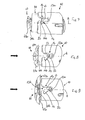
- the needle assembly 1 comprises a needle safety system for protecting the needle 5, in particular the distal tip 6 of the needle 5, at least in a storage condition of the needle assembly 1 as shown on Figure 1 and in an end-of-use condition (see Figure 13 ) of said needle assembly 1 after an injection step has been performed and the needle 5 has been removed from the injection site (not shown), in order to prevent accidental needlestick injuries for the user.
- the needle safety system comprises a fixed ring 10, which is fixed in translation with respect to the needle hub 4, a mobile ring 20, which is movable in translation with respect to the needle hub 4, a helical spring 30 coupling together the fixed ring 10 and the mobile ring 20, and a foldable member 40.
- the fixed ring 10 has the global shape of a portion of a tube having a proximal end 10a and a distal end 10b, and is provided on its inner wall with a proximal radial abutment surface formed of a circular ridge 11.
- the wall of the fixed ring 10 is further provided with three cams 12 regularly angularly distributed along a circumference of the fixed ring 10.
- the fixed ring 10 could be provided with a single cam or with two cams diametrically opposed.
- the fixed ring 10 could be provided with four or more cams.
- Each cam 12 comprises a longitudinal track 13 open at its distal end 13b, at the location where it rejoins the distal end 10b of the fixed ring 10, and closed at its proximal end 13a.
- Each cam 12 further comprises a side track 14, extending circumferentially and distally from a point of the longitudinal track 13. The side track 14 is closed at its distal end 14b, thereby forming a recess.
- the mobile ring 20 has also the global shape of a portion of a tube having a proximal end 20a and a distal end 20b, said mobile ring 20 being dimensioned so as to be able to be at least partially received within said fixed ring 10.
- the mobile ring 20 is provided on its inner wall with a distal radial abutment surface under the form of a circular ridge 21.
- the helical spring 30 is intended to couple the fixed ring 10 to the mobile ring 20, by having its proximal end 30a bearing on the proximal radial abutment formed by the circular ridge 11 of the fixed ring 10 and having its distal end 30b bearing on the distal radial abutment surface formed by the circular ridge 21 of the mobile ring 20.
- the mobile ring 20 is further provided on its outer wall with three pegs 22 (two only are visible on Figure 3 ) regularly angularly distributed along a circumference of the mobile ring 20 and capable of being received within the corresponding cams 12, so as to cooperate with said cams 12, in order to either retain the mobile ring 20 in a proximal position with respect to said fixed ring 10 or on the contrary to move said mobile ring 20 to a distal position with respect to said fixed ring 10, in combination with the helical spring 30.
- the number of pegs 22 could vary between 1 and 4 or more.
- the foldable member 40 has a globally elongated shape with a proximal end 40a and a distal end 40b, and having a longitudinal axis A corresponding to the longitudinal axis of the needle assembly 1. It is provided in its proximal region with a tubular portion 41.
- the tubular portion 41 is provided with a proximal inner rim 41 a at its proximal end.
- the tubular portion 41 is further provided on its outer wall with a window 41 b.
- the foldable member 40 is further provided at its distal end 40b with a protective ring 42, intended to protect the distal tip 6 of the needle 5 in the storage and end-of-use conditions of the needle assembly 1 of the invention, as will appear from the description below.
- the foldable member 40 is further provided with three legs 43 located between the tubular portion 41 and the protective ring 42, and regularly and angularly distributed around the longitudinal axis A, in the example shown.
- the three legs can be distributed around the longitudinal axis to form a U shape.
- each leg 43 is linked to the tubular portion 41 by means of a proximal hinge 44, and the distal end 43b of each leg 43 is linked to the protective ring 42 by means of a distal hinge 45.
- Each leg 43 is further provided with an intermediate hinge 46 dividing the length of said leg 43 in a proximal segment 47 and a distal segment 48.
- the proximal hinge 44 allows the proximal segment 47 of the leg 43 to pivot with respect to the tubular portion 41 in the radial outward direction
- the distal hinge 45 allows the distal segment 48 of the leg 43 to pivot with respect to the protective ring 42 in the radial outward direction
- the intermediate hinge 46 allows the proximal and distal segments (47, 48) to pivot with respect to each other, and the protective ring 42 is translated in the proximal direction along the longitudinal axis A.
- the foldable member 40 is capable of going from an unfolded configuration, as shown on Figure 4 , to a fully folded configuration, as shown on Figure 11 , while going through intermediate folded configurations, as shown on Figure 10 .
- the overall length of the foldable member 40 in other words the length of the member 40 from its proximal end 40a to its distal end 40b, measured along longitudinal axis A, and in particular the length of each leg 43, measured from its proximal end 43a to its distal end 43b along longitudinal axis A, is reduced when the foldable member 40, in particular each leg 43, goes from its unfolded configuration, as shown on Figure 4 , to an intermediate folded configuration, as shown on Figure 10 , or to its fully folded configuration, as shown on Figure 11 .
- the proximal segment 47 of each leg 43 has a proximal end 47a and is further provided in the distal region of its outer wall with an outer projection 47b and with a groove 47c, the groove 47c being proximally spaced with respect to said outer projection 47b.
- the protective ring 42 is capable of moving in translation with respect to the needle hub 4 between a distal position, in which the protective ring 42 surrounds at least the distal tip 6 of the needle 5 and in which the needle safety system is in one of a storage condition (as shown on Figure 1 ) or end-of-use condition (as shown on Figure 13 ), and a proximal position, in which the protective ring 42 leaves said distal tip 6 uncovered and wherein the needle safety system is in a use condition, said protective ring 42 being movable in said proximal position between intermediate positions, as shown on Figure 5 , in which the needle 5 is partially inserted into an injection site (not shown), and a most proximal position, in which the needle 5 is fully inserted in the injection site and where an injection step may take place, as shown on Figure 6 : as such, Figure 5 shows an intermediate condition of the needle assembly, in which the distal tip
- foldable means the foldable member 40 in the example shown, are coupled to the protective ring 42 and to the needle hub 4, and are capable of going from an unfolded configuration, in which the protective ring 42 is in its distal position, as shown on Figure 4 , to a fully folded configuration, in which the protective ring 42 is in its most proximal position, as shown on Figure 11 . Between its most proximal position and its distal position, the protective ring 42 may be in an intermediate position, corresponding to an intermediate folded configuration of the foldable means, as shown on Figure 10 .
- biasing means the helical spring 30 in the example shown, are capable of expanding from a stressed state to a rest state for urging the foldable means, the foldable member 40 in the example shown, from their fully folded configuration to their unfolded configuration at the end of the injection step.
- the user is provided with the needle assembly 1 of the invention in a storage condition of the needle assembly 1, corresponding to a condition of the needle assembly before use, as shown on Figures 1 and 2 .
- the needle hub 4 is a part of the container 2 intended to receive the product to be injected in an injection site (not shown) via the injection device 3 formed by the needle assembly 1 and the container 2.
- the stopper intended to close the proximal end of the container once it is filled and the piston rod intended to move the stopper distally so as to perform injection are not shown.
- the needle hub 4 is received within the tubular portion 41 of the foldable member 40.
- the tubular portion 41 as such does not constitute a foldable part of the foldable member 40 and this tubular portion 41 is fixed in translation with respect to the needle hub 4 by means of its proximal inner rim 41 a being engaged in the circular groove 7 of the needle hub 4.
- the foldable member 40 is in its unfolded configuration, as shown on Figure 4 , and the protective ring 42 is therefore in its distal position, thus surrounding and protecting the distal tip 6 of the needle 5.
- the needle hub of the needle assembly is not a part of the container but an independent piece having the needle 5 fixed thereon.
- the needle hub may be received within the tubular portion of the foldable member, or the needle hub and the tubular portion may form a single piece. In both cases, the needle hub is fixed in translation with respect to the distal end of the container.
- the tubular portion 41 of the foldable member 40 is received within the fixed ring 10, this tubular portion 41 being fixed in translation with respect to the fixed ring 10 by means of its window 41 b engaging the circular ridge 11 of the fixed ring 10.
- the fixed ring 10 is fixed in translation with respect to the needle hub 4, by the intermediate of the tubular portion 41.
- the mobile ring 20 is partially received in the fixed ring 10, said mobile ring 20 being coupled to the fixed ring 10 by means of the helical spring 30.
- the proximal end 30a of the helical spring 30 bears on the proximal radial abutment surface formed by the circular ridge 11 of the fixed ring 10
- the distal end 30b of the helical spring 30 bears on the distal radial abutment surface formed by the circular ridge 21 of the mobile ring 20.
- the helical spring 30 is maintained in an intermediate stressed state by means of peg 22 of mobile ring 20 being engaged in the distal end 14b of the side track 14 of the cam 12 of the fixed ring 10, said distal end 14b forming a recess in which said peg 22 is blocked, said peg 22 being therefore in a locked state.
- the peg 22 and the distal closed end 14b of the side track 14 therefore form retaining means for maintaining the helical spring 30 in its intermediate stressed state in the storage condition of the needle assembly 1.
- the peg 22 is located on the mobile ring 20. In embodiments not shown, the peg could be located on the foldable means 40.
- the mobile ring 20 In the storage condition of the needle assembly 1 as shown on Figure 1 , the mobile ring 20 is therefore blocked in distal translation with respect to the fixed ring 10. In addition, as will appear from the following description, it is limitedly movable in proximal translation and in rotation with respect to the fixed ring 10, said proximal translation and rotation being conditioned to the cooperation of the peg 22 within the cam 12.
- the user grasps the injection device 3, for example by the container 2, and applies the distal end of the injection device 3, in other words the distal end of the protective ring 42 on the skin of the patient (not shown).
- the product to be injected, the stopper and the piston rod are not shown.
- the protective ring 42 is applied on the skin of the patient, the user applies a distal force on the proximal end of the injection device 3, thereby causing the insertion of the needle 5 in the skin of the patient.
- Such a movement causes the proximal movement of the protective ring 42 with respect to the needle hub 4, as shown on Figure 5 .
- the protective ring 42 being linked to the legs 43 by means of distal hinges 45, the distal segments 48 are caused to pivot with respect to the protective ring 42, the proximal segments 47 are caused to pivot with respect to the distal segments 48 via intermediate hinges 46, and to pivot with respect to the tubular portion 41 and to the needle hub 4 via proximal hinges 44.
- the foldable member 40 is caused to move to an intermediate folded configuration, as shown on Figures 5 and 10 .
- the proximal segment 47 of each leg 43 has been caused to expand radially outwardly as shown on Figure 5 , and more precisely on Figure 8 .
- the proximal movement of the mobile ring 20 causes the peg 22 to move within the cam 12, and in particular in side track 14, therefore acting as a guiding means of peg 22 so as to cause rotation and proximal translation of the mobile ring 20 with respect to the fixed ring 10.
- peg 22 escapes from side track 14 and enters longitudinal track 13, as shown on Figure 8 , said peg 22 being therefore in a free state.
- the retaining means of the helical spring are therefore released, the proximal end 47a of the proximal segment 47 and the mobile ring 20 having acted as deactivating means of these retaining means.
- the distal end 47a of the proximal segment 47 comes in abutment against the distal end 20b of the mobile ring 20, pushes the distal end 20b in the proximal direction leading indirectly via the movement of the peg 22 to the release of the retaining means of the helical spring 30.
- the peg 22 is not yet allowed to travel in the longitudinal track 13 in a distal direction and the helical spring 30 is therefore maintained in an intermediate stressed state.
- the user then carries on the insertion step of the needle 5 and continues to exert a distal pressure on the injection device 3 in order to fully insert the needle 5 up to the adequate injection site (not shown).
- the needle assembly 1 and injection device 3 of the invention once the needle 5 is fully inserted up to the injection site and the injection step as such may properly take place.
- the needle assembly 1 and the injection device 3 are therefore in a use condition, in which the needle 5 is fully inserted and the injection device 3 is ready for injection step.
- the protective ring 42 has continued to move in the proximal direction and has now reached its most proximal position.
- the foldable member 40 has left his intermediate folded configuration shown on Figure 10 in order to reach his fully folded configuration shown on Figure 11 .
- This has caused the proximal segment 47 to reach a nearly perpendicular position with respect to the longitudinal axis A, as shown on Figure 6 .
- the proximal end 47a of the proximal segment 47 has kept on pushing the mobile ring 20 in proximal direction via its distal end 20b.
- This has caused the peg 22 to move in the longitudinal track 13 in the proximal direction up to the proximal end 13a of said longitudinal track 13a.
- the peg 22 coming in abutment against the closed proximal end 13a of the longitudinal track 13 forms therefore an indication to the user that the needle 5 is fully inserted in the injection site and that the injection step may be started.
- This movement has also exerted an additional compression on the helical spring 30 and has therefore caused the helical spring 30 to move from its intermediate stressed state to its stressed state, said stressed state corresponding to the most stressed state reachable by the helical spring in the example shown.
- the user may perform the injection as such.
- This step is not shown on the figures as it consists in expelling the product from the container by pushing distally on the piston rod, said operations having no interaction with the needle assembly of the invention.
- the user continues applying enough distal pressure on the injection device 3 and thus on needle assembly 1, so that the peg 22 remains in its position shown on Figure 9 , in abutment against closed distal end 13a of longitudinal track 13 of cam 12, the helical spring 30 being in its stressed state.
- the user withdraws the injection device 3, thereby removing the needle 5 from the injection site and relieving his distal pressure on the injection device 3.
- the peg 22 is free to move in the distal direction in the longitudinal track 13 and no more acts as retaining means of the helical spring 30 in his stressed sate.
- the helical spring 30 tends to reach his rest state and automatically expands, thereby pushing the mobile ring 20 in the distal direction, said peg 22 escaping definitely the cam 12 and the fixed ring 10 by exiting the longitudinal track 13 by its open distal end 13b (see Figure 9 ).
- the distal movement of the mobile ring 20 pushed by the helical spring 30 causes the distal end 20b of the mobile ring 20 to push distally the proximal end 47a of the proximal segment 47 which thus pivot back radially inwardly, thereby urging the whole foldable member 40 to its unfolded configuration as shown on Figure 13 .
- the protective ring 42 is back to his distal position, in which it surrounds the distal tip 6 of the needle 5 and protects the user from accidental needlestick injuries.
- the biasing means forms automatic means for triggering the needle safety system of the needle assembly 1 of the invention when the needle is removed from the injection site at the end of the injection step, with no additional operation requested from the user, other than withdrawing the injection device 3 from the injection site.
- the mobile ring 20 In the end-of-use condition of the needle assembly 1 and injection device 3 as shown on Figure 13 , the mobile ring 20 is in a distal position with respect to the needle hub 4 and the fixed ring 10, in which it receives at least part of the foldable member 40.
- the circular ridge 21 of the mobile ring 20 is now engaged in the window 47c of the proximal segment 47 of the leg 43 of the foldable member 40, and the distal end 20b of the mobile ring 20 is in abutment against the outer projection 47b of said proximal segment 47.
- the foldable member 40 is not allowed to move towards an intermediate folded configuration.
- the mobile ring 20, the circular ridge 21, the window 47c, the distal end 20b and the outer projection 47b form locking means of the foldable member in its unfolded configuration, in said end-of-use condition of the needle assembly 1.
- a cap intended to be mounted on the needle assembly 1 when the needle assembly 1 is in a storage condition, as shown on Figure 1 , for example for transportation purposes.
- the protective cap 50 is dimensioned so as to surround the needle assembly 1.
- the protective cap 50 has the global shape of a tube open at its proximal end 50a and closed at its distal end 50b.
- the protective cap 50 comprises an elastomeric part 51 extending proximally from an inner face 52a of a transversal wall 52 closing its distal end 50b.
- the elastomeric part 51 is dimensioned so as to be able to be received within the protective ring 42 when the protective cap 50 is mounted on the needle assembly 1, and the distal tip 6 of the needle 5 is intended to be received in the elastomeric part 51.
- the elastomeric part 51 can be in different materials, in rubber for example or preferably in an elastomeric material, like thermoplastic elastomers (TPE) as styrenic block copolymers, polyolefin blends, elastomeric alloys, thermoplastic polyurethanes, thermoplastic copolyester or thermoplastic polyamides.
- TPE thermoplastic elastomers
- the protective cap 50 is further provided on a certain length of its inner wall with a longitudinal ridge 53, said longitudinal ridge having a proximal end 53a.
- the proximal end 53a of the longitudinal ridge 53 is directed towards the open distal end 13a of the longitudinal track 13 of the cam 12, so that the proximal region of the longitudinal ridge 53 is engaged in the longitudinal track 13 during storage and/or transportation of the needle assembly 1 provided with said protective cap 50, said longitudinal ridge 53 preventing said peg 22 from escaping from said side track 14.
- the longitudinal ridge 53 of the protective cap therefore forms securing means for preventing the biasing means from being accidentally triggered.
- the foldable member 40 comprises three legs 43. Such an embodiment allows obtaining a good stability of the foldable member 40 during its changes of configurations. Nevertheless, in other embodiments, the foldable member 40 may comprise only one leg or only two legs opposite each other with respect to the needle. The foldable member may also comprise four or more legs, distributed around the needle.
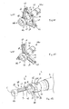
- FIG. 12 is shown another embodiment of the needle assembly 1 of the invention, in which the foldable member 40 comprises only one leg 43, parallel to the needle 5.
- the references designating the same elements as in Figures 1-11 and 13 have been maintained on Figures 12 and 16 .
- the single leg 43 of the embodiment on these Figures functions exactly in the same manner as the legs 43 of Figures 1-11 and 13 and it will not be described again herein.
- the needle assembly 1 is in its storage condition, with the peg 22 in its locked state.
- the fixed ring 10 of this embodiment is further provided with tongues 15, three in the example shown, extending in the proximal direction.
- tongues 15 are circumferentially spaced from the open end 13a of the longitudinal track 13 of cams 12, and from the leg 43, so as to allow the proximal segment 47 to expand radially outwardly when the foldable member 40 moves to its folded configuration.
- These tongues 15 provide protection of the helical spring 30 when it is in its rest state in the end-of-use condition of the needle assembly 1, as shown on Figure 16 .
- the tongues 15 act as protection means of the helical spring 30 in its rest state so as to prevent access to said helical spring 30 to a user.
- the tongues 15 are further provided with fingers 16 radially flexible in windows 17 provided in tongues 15, these fingers 16 being capable of engaging an outer rim 23 provided at the proximal end of the mobile ring 20 so that the fixed ring 10 and the mobile ring 20 form a continuous protective wall of the helical spring 30 in the end-of-use condition of the needle assembly 1, as shown on Figure 16 .
- the tongues 15 do not include such windows and flexible fingers, and the mobile ring 20 is not provided with such an outer rim, the fixed ring 10 and the mobile ring 20 nevertheless forming a continuous protective wall of the helical spring 30 in the end-of-use condition of the needle assembly 1.
- the alternative embodiments of the fixed ring 10 and mobile ring 20 may also be combined with the embodiment of Figures 1-11 and 13 , where the foldable member 40 comprises three legs 43.
- Such protection obtained by the tongues 15 of the fixed ring 10 may be required in order to avoid any voluntary unlocking of the safety system in the end-of-use condition. Indeed, with this embodiment of the fixed ring 10, the tongues 15 and the mobile ring 20 are at the same level along longitudinal axis A, thereby preventing any possibility to move the needle assembly 1 from an end-of use condition to a storage condition.
- the needle assembly of the invention allows obtaining compact injection devices, occupying little volume and therefore easy to package and to store, even when these injection devices are prefilled with the product to be injected, the injection devices being in addition provided with an efficient needle safety system allowing the automatic triggering of the needle protection at the end of injection or after a misuse of the injection device, with no additional operation requested from the user other than withdrawing the injection device from the injection site.
Priority Applications (9)
| Application Number | Priority Date | Filing Date | Title |
|---|---|---|---|
| EP11305423A EP2510964A1 (fr) | 2011-04-11 | 2011-04-11 | Ensemble formant aiguille et dispositif d'injection avec un moyen de protection de l'aiguille pliant |
| JP2014504204A JP6430827B2 (ja) | 2011-04-11 | 2012-04-10 | 折り畳み可能な針保護手段を備えた針アセンブリおよび注射装置 |
| EP12713885.7A EP2696921B1 (fr) | 2011-04-11 | 2012-04-10 | Ensemble aiguille et dispositif d'injection avec moyens de protection d'aiguille pouvant être pliés |
| RU2013149704/14A RU2564406C2 (ru) | 2011-04-11 | 2012-04-10 | Игольный блок и устройство для инъекции со складными средствами защиты иглы |
| US14/110,851 US9764097B2 (en) | 2011-04-11 | 2012-04-10 | Needle assembly and injection device with foldable needle protecting means |
| PCT/EP2012/001544 WO2012139745A1 (fr) | 2011-04-11 | 2012-04-10 | Ensemble aiguille et dispositif d'injection avec moyens de protection d'aiguille pouvant être pliés |
| ES12713885.7T ES2665507T3 (es) | 2011-04-11 | 2012-04-10 | Conjunto de aguja y dispositivo de inyección con medios protectores de aguja plegable |
| CN201280015302.5A CN103458947B (zh) | 2011-04-11 | 2012-04-10 | 具有可折叠针保护装置的针组件和注射装置 |
| KR1020137026443A KR101640648B1 (ko) | 2011-04-11 | 2012-04-10 | 절첩식 니들 보호 수단을 구비한 니들 조립체 및 주입 장치 |
Applications Claiming Priority (1)
| Application Number | Priority Date | Filing Date | Title |
|---|---|---|---|
| EP11305423A EP2510964A1 (fr) | 2011-04-11 | 2011-04-11 | Ensemble formant aiguille et dispositif d'injection avec un moyen de protection de l'aiguille pliant |
Publications (1)
| Publication Number | Publication Date |
|---|---|
| EP2510964A1 true EP2510964A1 (fr) | 2012-10-17 |
Family
ID=45953068
Family Applications (2)
| Application Number | Title | Priority Date | Filing Date |
|---|---|---|---|
| EP11305423A Withdrawn EP2510964A1 (fr) | 2011-04-11 | 2011-04-11 | Ensemble formant aiguille et dispositif d'injection avec un moyen de protection de l'aiguille pliant |
| EP12713885.7A Active EP2696921B1 (fr) | 2011-04-11 | 2012-04-10 | Ensemble aiguille et dispositif d'injection avec moyens de protection d'aiguille pouvant être pliés |
Family Applications After (1)
| Application Number | Title | Priority Date | Filing Date |
|---|---|---|---|
| EP12713885.7A Active EP2696921B1 (fr) | 2011-04-11 | 2012-04-10 | Ensemble aiguille et dispositif d'injection avec moyens de protection d'aiguille pouvant être pliés |
Country Status (8)
| Country | Link |
|---|---|
| US (1) | US9764097B2 (fr) |
| EP (2) | EP2510964A1 (fr) |
| JP (1) | JP6430827B2 (fr) |
| KR (1) | KR101640648B1 (fr) |
| CN (1) | CN103458947B (fr) |
| ES (1) | ES2665507T3 (fr) |
| RU (1) | RU2564406C2 (fr) |
| WO (1) | WO2012139745A1 (fr) |
Cited By (3)
| Publication number | Priority date | Publication date | Assignee | Title |
|---|---|---|---|---|
| CN104056320A (zh) * | 2014-06-23 | 2014-09-24 | 河南科技大学第一附属医院 | 一种医用注射加药装置 |
| EP2826519A1 (fr) * | 2013-07-15 | 2015-01-21 | Becton Dickinson France | Adaptateur pour un dispositif d'administration de médicament et procédé pour monter ledit adaptateur sur celui-ci |
| US20150359974A1 (en) * | 2011-07-25 | 2015-12-17 | Safety Syringes, Inc. | Folding panel needle guard |
Families Citing this family (12)
| Publication number | Priority date | Publication date | Assignee | Title |
|---|---|---|---|---|
| EP3102255A1 (fr) * | 2014-02-06 | 2016-12-14 | Novo Nordisk A/S | Cartouche et ensemble aiguille en combinaison |
| CN104307072A (zh) | 2014-10-29 | 2015-01-28 | 杭州普昂医疗科技有限公司 | 安全式胰岛素笔针 |
| GB2533620B (en) * | 2014-12-23 | 2018-06-06 | Owen Mumford Ltd | Skin pricking device |
| WO2017218372A1 (fr) * | 2016-06-15 | 2017-12-21 | Bayer Healthcare Llc | Système jetable à usages multiples et seringue associée |
| US10814073B2 (en) * | 2016-12-13 | 2020-10-27 | Becton, Dickinson And Company | Safety device with collapsible housing and trigger activation |
| WO2019053112A1 (fr) * | 2017-09-14 | 2019-03-21 | Becton Dickinson France | Ensemble de sécurité |
| EP3520846A1 (fr) * | 2018-01-31 | 2019-08-07 | Becton Dickinson France | Dispositif de protection pour une aiguille |
| WO2019149655A1 (fr) * | 2018-01-31 | 2019-08-08 | Becton Dickinson France | Dispositif de protection pour une aiguille |
| JP7246369B2 (ja) * | 2018-03-16 | 2023-03-27 | テルモ株式会社 | 皮内針及びその包装体並びに注射装置 |
| US10853467B2 (en) | 2018-03-28 | 2020-12-01 | Bank Of America Corporation | Data access control using multi-device multifactor authentication |
| WO2020111295A1 (fr) * | 2018-11-27 | 2020-06-04 | 주식회사 대웅제약 | Capuchon de sécurité pour seringue et seringue de sécurité le comprenant |
| JP2022549160A (ja) * | 2019-09-17 | 2022-11-24 | ベクトン ディキンソン ホールディングス ピーティーイー リミテッド | 受動安全装置、それを含む注射装置、及び前記注射装置を製造するための方法 |
Citations (5)
| Publication number | Priority date | Publication date | Assignee | Title |
|---|---|---|---|---|
| US5201708A (en) * | 1992-02-03 | 1993-04-13 | Timothy A. Kershenstine | Self-locking safety syringe |
| US20020165498A1 (en) * | 2001-05-04 | 2002-11-07 | Becton, Dickinson And Company | Passively acivated safety needle |
| US20050059936A1 (en) * | 2001-03-02 | 2005-03-17 | Fiser Richard L. | Passive safety shield |
| US6986759B1 (en) * | 1998-05-15 | 2006-01-17 | Device Research & Development (Drd) | Device for protecting and neutralizing a needle for medical use |
| US20080051724A1 (en) * | 2003-02-14 | 2008-02-28 | Bedford Anthony J | Safety device with trigger mechanism |
Family Cites Families (11)
| Publication number | Priority date | Publication date | Assignee | Title |
|---|---|---|---|---|
| US4935013A (en) * | 1988-02-23 | 1990-06-19 | Habley Medical Technology Corporation | Collapsible needle cover |
| US5487733A (en) | 1994-09-20 | 1996-01-30 | Becton, Dickinson And Company | Assembly with collapsible sheath and tip guard |
| US5512050A (en) * | 1994-09-20 | 1996-04-30 | Becton, Dickinson And Company | Needle assembly with collapsible and retractable sheath |
| US5607400A (en) * | 1995-05-19 | 1997-03-04 | Becton, Dickinson And Company | Pre-fillable syringe and stopper assembly therefor |
| US5562631A (en) * | 1995-06-07 | 1996-10-08 | Johnson & Johnson Medical, Inc. | Catheter arrangement with interlocking sequenced guarding members for protecting cannula |
| US5591138A (en) * | 1995-08-10 | 1997-01-07 | Vaillancourt; Vincent L. | Protected needle assembly |
| US7029461B2 (en) * | 1999-11-04 | 2006-04-18 | Tyco Healthcare Group Lp | Safety shield for medical needles |
| US6171284B1 (en) * | 2000-03-15 | 2001-01-09 | Wang-Hsiang Kao | Syringe needle cover structure |
| US8066678B2 (en) * | 2001-12-17 | 2011-11-29 | Bard Access Systems, Inc. | Safety needle with collapsible sheath |
| GB2398248A (en) * | 2003-02-14 | 2004-08-18 | Scient Generics Ltd | Safety device with trigger mechanism |
| FR2930162B1 (fr) * | 2008-04-16 | 2011-05-13 | Becton Dickinson France | Ensemble de protection d'aiguille comportant un element de verrouillage. |
-
2011
- 2011-04-11 EP EP11305423A patent/EP2510964A1/fr not_active Withdrawn
-
2012
- 2012-04-10 KR KR1020137026443A patent/KR101640648B1/ko active IP Right Grant
- 2012-04-10 US US14/110,851 patent/US9764097B2/en active Active
- 2012-04-10 EP EP12713885.7A patent/EP2696921B1/fr active Active
- 2012-04-10 WO PCT/EP2012/001544 patent/WO2012139745A1/fr active Application Filing
- 2012-04-10 RU RU2013149704/14A patent/RU2564406C2/ru active
- 2012-04-10 JP JP2014504204A patent/JP6430827B2/ja active Active
- 2012-04-10 ES ES12713885.7T patent/ES2665507T3/es active Active
- 2012-04-10 CN CN201280015302.5A patent/CN103458947B/zh active Active
Patent Citations (5)
| Publication number | Priority date | Publication date | Assignee | Title |
|---|---|---|---|---|
| US5201708A (en) * | 1992-02-03 | 1993-04-13 | Timothy A. Kershenstine | Self-locking safety syringe |
| US6986759B1 (en) * | 1998-05-15 | 2006-01-17 | Device Research & Development (Drd) | Device for protecting and neutralizing a needle for medical use |
| US20050059936A1 (en) * | 2001-03-02 | 2005-03-17 | Fiser Richard L. | Passive safety shield |
| US20020165498A1 (en) * | 2001-05-04 | 2002-11-07 | Becton, Dickinson And Company | Passively acivated safety needle |
| US20080051724A1 (en) * | 2003-02-14 | 2008-02-28 | Bedford Anthony J | Safety device with trigger mechanism |
Cited By (7)
| Publication number | Priority date | Publication date | Assignee | Title |
|---|---|---|---|---|
| US20150359974A1 (en) * | 2011-07-25 | 2015-12-17 | Safety Syringes, Inc. | Folding panel needle guard |
| US9925341B2 (en) * | 2011-07-25 | 2018-03-27 | Safety Syringes, Inc. | Folding panel needle guard |
| EP2826519A1 (fr) * | 2013-07-15 | 2015-01-21 | Becton Dickinson France | Adaptateur pour un dispositif d'administration de médicament et procédé pour monter ledit adaptateur sur celui-ci |
| WO2015007650A1 (fr) * | 2013-07-15 | 2015-01-22 | Becton Dickinson France | Adaptateur de dispositif d'administration de médicament et procédé de montage sur celui-ci dudit adaptateur |
| RU2640946C2 (ru) * | 2013-07-15 | 2018-01-12 | Бектон Дикинсон Франс | Адаптер для устройства доставки лекарственного средства и способ установки указанного адаптера на нем |
| US10258540B2 (en) | 2013-07-15 | 2019-04-16 | Becton Dickinson France | Adaptor for a drug delivery device and method for mounting said adaptor thereon |
| CN104056320A (zh) * | 2014-06-23 | 2014-09-24 | 河南科技大学第一附属医院 | 一种医用注射加药装置 |
Also Published As
| Publication number | Publication date |
|---|---|
| KR101640648B1 (ko) | 2016-07-22 |
| US9764097B2 (en) | 2017-09-19 |
| JP2014514074A (ja) | 2014-06-19 |
| EP2696921B1 (fr) | 2018-01-24 |
| CN103458947B (zh) | 2015-11-25 |
| WO2012139745A1 (fr) | 2012-10-18 |
| KR20140015450A (ko) | 2014-02-06 |
| EP2696921A1 (fr) | 2014-02-19 |
| US20140039408A1 (en) | 2014-02-06 |
| CN103458947A (zh) | 2013-12-18 |
| RU2564406C2 (ru) | 2015-09-27 |
| ES2665507T3 (es) | 2018-04-26 |
| RU2013149704A (ru) | 2015-05-20 |
| JP6430827B2 (ja) | 2018-11-28 |
Similar Documents
| Publication | Publication Date | Title |
|---|---|---|
| EP2696921B1 (fr) | Ensemble aiguille et dispositif d'injection avec moyens de protection d'aiguille pouvant être pliés | |
| EP1946789B1 (fr) | Système d'écran de sécurité pour seringues préremplies | |
| KR102565164B1 (ko) | 안전 바늘 커버를 구비한, 조성물을 주입하기 위한 의료용 장치 | |
| US9526837B2 (en) | Automatic injection device | |
| DK2536454T3 (en) | Auto-injector with delay mechanism | |
| US6616639B2 (en) | Safety shield system for syringes | |
| ES2548175T3 (es) | Auto-inyector | |
| RU2578178C2 (ru) | Инъектор | |
| EP1392379B1 (fr) | Systeme de protection de surete pour seringues preremplies | |
| EP2544739B1 (fr) | Auto-injecteur | |
| ES2581481T3 (es) | Auto-inyector | |
| US9533099B2 (en) | Automatic injection device | |
| EP1397172B1 (fr) | Systeme de gaine de securite pour seringues preremplies | |
| EP3697480B1 (fr) | Dispositif de sécurité intégrée passive et dispositif d'injection comprenant ce dispositif de sécurité intégrée passive | |
| RU2575310C2 (ru) | Инъектор |
Legal Events
| Date | Code | Title | Description |
|---|---|---|---|
| PUAI | Public reference made under article 153(3) epc to a published international application that has entered the european phase |
Free format text: ORIGINAL CODE: 0009012 |
|
| AK | Designated contracting states |
Kind code of ref document: A1 Designated state(s): AL AT BE BG CH CY CZ DE DK EE ES FI FR GB GR HR HU IE IS IT LI LT LU LV MC MK MT NL NO PL PT RO RS SE SI SK SM TR |
|
| AX | Request for extension of the european patent |
Extension state: BA ME |
|
| STAA | Information on the status of an ep patent application or granted ep patent |
Free format text: STATUS: THE APPLICATION IS DEEMED TO BE WITHDRAWN |
|
| 18D | Application deemed to be withdrawn |
Effective date: 20130418 |