EP3554326B1 - Heat management for food processor - Google Patents
Heat management for food processor Download PDFInfo
- Publication number
- EP3554326B1 EP3554326B1 EP17822593.4A EP17822593A EP3554326B1 EP 3554326 B1 EP3554326 B1 EP 3554326B1 EP 17822593 A EP17822593 A EP 17822593A EP 3554326 B1 EP3554326 B1 EP 3554326B1
- Authority
- EP
- European Patent Office
- Prior art keywords
- machine
- motor
- impeller
- air
- container
- Prior art date
- Legal status (The legal status is an assumption and is not a legal conclusion. Google has not performed a legal analysis and makes no representation as to the accuracy of the status listed.)
- Active
Links
- 235000013305 food Nutrition 0.000 title claims description 18
- 230000005291 magnetic effect Effects 0.000 claims description 39
- 239000000126 substance Substances 0.000 claims description 31
- 239000008267 milk Substances 0.000 claims description 24
- 235000013336 milk Nutrition 0.000 claims description 24
- 210000004080 milk Anatomy 0.000 claims description 24
- 235000021056 liquid food Nutrition 0.000 claims description 21
- PXHVJJICTQNCMI-UHFFFAOYSA-N Nickel Chemical compound [Ni] PXHVJJICTQNCMI-UHFFFAOYSA-N 0.000 claims description 15
- 230000005540 biological transmission Effects 0.000 claims description 15
- XEEYBQQBJWHFJM-UHFFFAOYSA-N Iron Chemical compound [Fe] XEEYBQQBJWHFJM-UHFFFAOYSA-N 0.000 claims description 12
- 230000008878 coupling Effects 0.000 claims description 10
- 238000010168 coupling process Methods 0.000 claims description 10
- 238000005859 coupling reaction Methods 0.000 claims description 10
- 229910016583 MnAl Inorganic materials 0.000 claims description 9
- 229910017034 MnSn Inorganic materials 0.000 claims description 9
- 230000005294 ferromagnetic effect Effects 0.000 claims description 9
- 238000004140 cleaning Methods 0.000 claims description 8
- 229910016964 MnSb Inorganic materials 0.000 claims description 6
- AYTAKQFHWFYBMA-UHFFFAOYSA-N chromium dioxide Chemical compound O=[Cr]=O AYTAKQFHWFYBMA-UHFFFAOYSA-N 0.000 claims description 6
- 229910052742 iron Inorganic materials 0.000 claims description 6
- JEIPFZHSYJVQDO-UHFFFAOYSA-N iron(III) oxide Inorganic materials O=[Fe]O[Fe]=O JEIPFZHSYJVQDO-UHFFFAOYSA-N 0.000 claims description 6
- -1 lanthanide Chemical compound 0.000 claims description 6
- 230000033001 locomotion Effects 0.000 claims description 6
- 230000000694 effects Effects 0.000 claims description 4
- 229910003396 Co2FeSi Inorganic materials 0.000 claims description 3
- 229910018301 Cu2MnAl Inorganic materials 0.000 claims description 3
- 229910016555 CuOFe2O3 Inorganic materials 0.000 claims description 3
- 229910052692 Dysprosium Inorganic materials 0.000 claims description 3
- 229910016697 EuO Inorganic materials 0.000 claims description 3
- 229910017384 Fe3Si Inorganic materials 0.000 claims description 3
- 229910015191 FeOFe2O3 Inorganic materials 0.000 claims description 3
- 229910052688 Gadolinium Inorganic materials 0.000 claims description 3
- 229910016987 MnOFe2O3 Inorganic materials 0.000 claims description 3
- 229910017028 MnSi Inorganic materials 0.000 claims description 3
- 229910005408 Ni2MnGa Inorganic materials 0.000 claims description 3
- 229910005483 Ni2MnSb Inorganic materials 0.000 claims description 3
- 229910005857 NiOFe2O3 Inorganic materials 0.000 claims description 3
- 229910009493 Y3Fe5O12 Inorganic materials 0.000 claims description 3
- 229910045601 alloy Inorganic materials 0.000 claims description 3
- 239000000956 alloy Substances 0.000 claims description 3
- 229910017052 cobalt Inorganic materials 0.000 claims description 3
- 239000010941 cobalt Substances 0.000 claims description 3
- GUTLYIVDDKVIGB-UHFFFAOYSA-N cobalt atom Chemical compound [Co] GUTLYIVDDKVIGB-UHFFFAOYSA-N 0.000 claims description 3
- 239000012530 fluid Substances 0.000 claims description 3
- 230000001939 inductive effect Effects 0.000 claims description 3
- 229910052747 lanthanoid Inorganic materials 0.000 claims description 3
- 150000002602 lanthanoids Chemical class 0.000 claims description 3
- CPLXHLVBOLITMK-UHFFFAOYSA-N magnesium oxide Inorganic materials [Mg]=O CPLXHLVBOLITMK-UHFFFAOYSA-N 0.000 claims description 3
- 229910052748 manganese Inorganic materials 0.000 claims description 3
- 229910052751 metal Inorganic materials 0.000 claims description 3
- 239000002184 metal Substances 0.000 claims description 3
- 150000002739 metals Chemical class 0.000 claims description 3
- 229910001172 neodymium magnet Inorganic materials 0.000 claims description 3
- 229910052759 nickel Inorganic materials 0.000 claims description 3
- 230000002093 peripheral effect Effects 0.000 claims description 3
- 229920003023 plastic Polymers 0.000 claims description 3
- 239000004033 plastic Substances 0.000 claims description 3
- 229920000642 polymer Polymers 0.000 claims description 3
- 229910052761 rare earth metal Inorganic materials 0.000 claims description 3
- 150000002910 rare earth metals Chemical class 0.000 claims description 3
- 235000013353 coffee beverage Nutrition 0.000 description 9
- 238000010438 heat treatment Methods 0.000 description 7
- 238000003756 stirring Methods 0.000 description 7
- 235000013361 beverage Nutrition 0.000 description 5
- 239000007788 liquid Substances 0.000 description 5
- 239000000463 material Substances 0.000 description 3
- 230000009347 mechanical transmission Effects 0.000 description 3
- 244000299461 Theobroma cacao Species 0.000 description 2
- 230000009471 action Effects 0.000 description 2
- 230000003750 conditioning effect Effects 0.000 description 2
- 238000000034 method Methods 0.000 description 2
- 230000008569 process Effects 0.000 description 2
- 235000005764 Theobroma cacao ssp. cacao Nutrition 0.000 description 1
- 235000005767 Theobroma cacao ssp. sphaerocarpum Nutrition 0.000 description 1
- 230000003213 activating effect Effects 0.000 description 1
- 238000010009 beating Methods 0.000 description 1
- 235000001046 cacaotero Nutrition 0.000 description 1
- 235000015116 cappuccino Nutrition 0.000 description 1
- 239000002775 capsule Substances 0.000 description 1
- 235000019219 chocolate Nutrition 0.000 description 1
- 238000001816 cooling Methods 0.000 description 1
- 238000006073 displacement reaction Methods 0.000 description 1
- 235000013601 eggs Nutrition 0.000 description 1
- 239000010794 food waste Substances 0.000 description 1
- 235000011389 fruit/vegetable juice Nutrition 0.000 description 1
- 235000012171 hot beverage Nutrition 0.000 description 1
- 235000020278 hot chocolate Nutrition 0.000 description 1
- 238000010348 incorporation Methods 0.000 description 1
- 239000004615 ingredient Substances 0.000 description 1
- 238000010907 mechanical stirring Methods 0.000 description 1
- 230000007246 mechanism Effects 0.000 description 1
- 235000020124 milk-based beverage Nutrition 0.000 description 1
- 102000004169 proteins and genes Human genes 0.000 description 1
- 108090000623 proteins and genes Proteins 0.000 description 1
- 239000007787 solid Substances 0.000 description 1
- 235000021055 solid food Nutrition 0.000 description 1
- 230000009466 transformation Effects 0.000 description 1
Images

Classifications
-
- A—HUMAN NECESSITIES
- A47—FURNITURE; DOMESTIC ARTICLES OR APPLIANCES; COFFEE MILLS; SPICE MILLS; SUCTION CLEANERS IN GENERAL
- A47J—KITCHEN EQUIPMENT; COFFEE MILLS; SPICE MILLS; APPARATUS FOR MAKING BEVERAGES
- A47J43/00—Implements for preparing or holding food, not provided for in other groups of this subclass
- A47J43/04—Machines for domestic use not covered elsewhere, e.g. for grinding, mixing, stirring, kneading, emulsifying, whipping or beating foodstuffs, e.g. power-driven
- A47J43/07—Parts or details, e.g. mixing tools, whipping tools
- A47J43/08—Driving mechanisms
-
- A—HUMAN NECESSITIES
- A47—FURNITURE; DOMESTIC ARTICLES OR APPLIANCES; COFFEE MILLS; SPICE MILLS; SUCTION CLEANERS IN GENERAL
- A47J—KITCHEN EQUIPMENT; COFFEE MILLS; SPICE MILLS; APPARATUS FOR MAKING BEVERAGES
- A47J43/00—Implements for preparing or holding food, not provided for in other groups of this subclass
- A47J43/04—Machines for domestic use not covered elsewhere, e.g. for grinding, mixing, stirring, kneading, emulsifying, whipping or beating foodstuffs, e.g. power-driven
- A47J43/046—Machines for domestic use not covered elsewhere, e.g. for grinding, mixing, stirring, kneading, emulsifying, whipping or beating foodstuffs, e.g. power-driven with tools driven from the bottom side
- A47J43/0465—Machines for domestic use not covered elsewhere, e.g. for grinding, mixing, stirring, kneading, emulsifying, whipping or beating foodstuffs, e.g. power-driven with tools driven from the bottom side with magnetic drive
-
- A—HUMAN NECESSITIES
- A47—FURNITURE; DOMESTIC ARTICLES OR APPLIANCES; COFFEE MILLS; SPICE MILLS; SUCTION CLEANERS IN GENERAL
- A47J—KITCHEN EQUIPMENT; COFFEE MILLS; SPICE MILLS; APPARATUS FOR MAKING BEVERAGES
- A47J43/00—Implements for preparing or holding food, not provided for in other groups of this subclass
- A47J43/04—Machines for domestic use not covered elsewhere, e.g. for grinding, mixing, stirring, kneading, emulsifying, whipping or beating foodstuffs, e.g. power-driven
- A47J43/07—Parts or details, e.g. mixing tools, whipping tools
- A47J43/08—Driving mechanisms
- A47J43/085—Driving mechanisms for machines with tools driven from the lower side
-
- B—PERFORMING OPERATIONS; TRANSPORTING
- B01—PHYSICAL OR CHEMICAL PROCESSES OR APPARATUS IN GENERAL
- B01F—MIXING, e.g. DISSOLVING, EMULSIFYING OR DISPERSING
- B01F33/00—Other mixers; Mixing plants; Combinations of mixers
- B01F33/45—Magnetic mixers; Mixers with magnetically driven stirrers
- B01F33/453—Magnetic mixers; Mixers with magnetically driven stirrers using supported or suspended stirring elements
-
- B—PERFORMING OPERATIONS; TRANSPORTING
- B01—PHYSICAL OR CHEMICAL PROCESSES OR APPARATUS IN GENERAL
- B01F—MIXING, e.g. DISSOLVING, EMULSIFYING OR DISPERSING
- B01F2101/00—Mixing characterised by the nature of the mixed materials or by the application field
- B01F2101/06—Mixing of food ingredients
- B01F2101/07—Mixing ingredients into milk or cream, e.g. aerating
Definitions
- the field of the invention pertains to machines for heating a food substance, such as milk or a milk-containing substance.
- the machine is provided with an impeller and a heat management arrangement.
- the best-known beverage of this type is a coffee of the cappuccino type. It comprises a liquid portion consisting of coffee topped by a layer of frothed milk which, because of its very much lower density, floats atop the surface of the liquid. In general, preparing one takes time, manipulation operations and cleaning.
- the most customary way of preparing a milk-based froth is to pour the desired amount of milk into the container, immerse a steam outlet pipe from a coffee machine in the container, agitating it up and down to introduce the air needed to form the froth.
- US Patent 6,318,247 relates to an appliance for preparing hot beverages or food with stirring such as hot chocolate, for example.
- Other devices for stirring food products are described in patent documents WO 2004/043213 or DE 196 24 648 .
- Stirring systems with a magnetic engagement type are described in documents US 2,932,493 , DE 1 131 372 , US 4,537,332 and US 6,712,497 .
- DE 89 15 094 relates to a refrigerated pot for dispensing a milk-based beverage.
- US Patent 3,356,349 discloses a stirring device that has a heated tank, magnetic drive means positioned under the tank for driving a hub located in the middle of the tank.
- the device has: an inner tank for receiving the liquid that is to be frothed, in which a rotatable stirrer is positioned; an outer stand holding the tank; drive and control means which are in a cavity located between the inner tank and the outer stand, and which communicate with a switch and electrical connections located on the outer surface of the stand; and disturbance means to optimise circulation of the milk during frothing.
- a steam source is associated with the stirring effect.
- the invention thus relates to a machine for processing a liquid food substance, such as milk or a milk-based substance.
- the liquid food substance can be aqueous, e.g. containing coffee and/or chocolate and/or cacao.
- the machine may be a standalone machine, e.g. directly pluggable to the mains via an electric cord, or may be integrated in a food processor arranged to process other food items or to carry out different food conditioning processes, the food processor itself being generally pluggable to the mains via an electric cord whereas the machine is a sub-part of the food processor.
- a food processor may be a beverage maker, such as a coffee maker, e.g. a beverage maker configured to prepare a beverage (such as coffee) from an ingredient capsule.
- the machine of the invention may advantageously be configured to froth and/or heat milk and optionally be associated, as a standalone machine or as an integrated machine, into a coffee maker.
- Standalone and integrated associations of milk frothing machines and coffee makers are for example disclosed in WO 2006/050900 , WO 2008/142154 , WO 2009/074555 , WO 2010/023312 and WO 2010/023313 .
- the machine can be a milk frother which operates by incorporating finely divided gas bubbles, e.g. air bubbles, into milk.
- gas bubbles e.g. air bubbles
- the machine When the machine is configured for incorporating gas bubbles into the milk, it may include an operating mode without incorporation of gas bubbles.
- the machine of the invention comprises the features of claim 1.
- the container may have a side wall and a bottom wall for delimiting its cavity.
- the container may have a lid to cover the cavity, e.g. as taught in WO 2008/142154 .
- the container can be generally cup-shaped or bowl-shaped or cylinder-shaped, the sidewall being generally upright and the bottom wall being generally flat or curved.
- the container can be provided with a thermally insulating outside material and/or with a handle, for seizure and optional displacement of the container by a human hand.
- a thermally insulating outside material and/or with a handle, for seizure and optional displacement of the container by a human hand.
- Such a configuration is particularly advantageous when the food is processed at a higher temperature exceeding e.g. 50°C or below 10°C.
- the heat evacuation means comprises one or more movable members that are driven by the motor and that are configured to circulate air in the motor chamber to evacuate heat therefrom.
- the heat evacuation means is configured to evacuate heat by the circulated air from the motor chamber out of such machine predominantly via one or more passages separate from the cavity.
- the heat evacuation means can be configured so that a ratio of the heat evacuated by the passages over the heat evacuated by the cavity is greater than 2.5, such as greater than 5, for example greater than 10, e.g. greater than 30.
- the temperature in the container originates mainly from the thermal conditioner (if any) and is not or only insignificantly influenced by the unwanted heat generated within the motor chamber, e.g. generated by the motor and/or other electrical devices. Indeed such unwanted heat is predominantly evacuated by the heat evacuation means to outside the machine without passing via the container.
- the same motor drives on the one hand the machine's impeller and on the other hand the movable members of the heat evacuation means.
- the action of the heat evacuation means can be easily arranged to follow an increase or decrease of the action of the motor and thus an increase or decrease of power consumed by the motor.
- the heat evacuation means may include a further arrangement for evacuating heat, e.g. as disclosed in PCT/EP16/063668 .
- the heat evacuation means includes a radiator, a dissipator, e.g. a ventilator, and/or a heat sink.
- the machine can have a heater for heating the liquid food substance.
- the machine can include a control unit for controlling the processing of the liquid food substance, such as for controlling the motor of the impeller.
- the control unit may be used to control the thermal conditioner, e.g. heater and/or cooler, when present.
- control unit is configured to control the heater for:
- the motor chamber has at least one opening for an exchange of air driven by the movable member(s) between the chamber and a space outside the chamber, e.g. a space outside such machine.
- the motor chamber has one or more air inlet openings for letting air into the chamber and one or more air outlet openings for letting air out of the chamber when the one or more movable members are driven by the motor.
- Such openings can be located on a machine external bottom face and/or machine external side face(s).
- Such openings or other parts of the motor chamber can be formed as a radiator or a heat sink to contribute to the evacuation of heat from the chamber.
- At least one of the air circulation member(s) can be formed as a wing, blade or vane.
- At least one of the air circulation member (s) may have:
- the air circulation member (s) may be mounted on an axle driven by the motor, such as on a motor's output shaft or an axle driven thereby, e.g. driven via a transmission by the output shaft such as via a gear transmission e.g. a toothed gear transmission.
- the air circulation member(s) and the impeller may be driven at a same rotational speed by the motor or at different rotational speeds.
- a gear arrangement transmits a rotational speed from the motor to the air circulation member (s) at a first transmission ratio and to the impeller at a second transmission ratio different to the first transmission ratio.
- the first transmission ratio may be greater or smaller than the second transmission ratio. Whether it is greater of smaller and to which extent it is greater or smaller, may be based on the desired rotational speed of the impeller in the container (e.g. depending on the shape of the impeller and the desired result of the liquid food processing) on the one hand and the desired rotational speed of the air circulation member(s) (e.g. depending on the shape, movement path and number of the air circulation member (s) and desired air flow in the motor chamber).
- a plurality of air circulation members can be mounted in a loop, e.g. in a circle, such as on a ring or a disc, about a rotation axis, optionally the air circulation members being generally evenly distributed along the loop.
- the air circulation members are arranged for form a fan driven by the motor.
- the motor chamber may have a generally centrally located axis and peripheral sidewall(s), the air circulation member(s) being driven by the motor in the motor chamber about the centrally located axis, between the centrally located and the sidewalls, such as at a distance from the centrally located axis in the range of 1/4 to 3/4 of the spacing from the centrally located axis to the sidewall at the level of the air circulation member, e.g. at a distance in the range of 1/3 to 2/3 of such spacing.
- the motor may drive a drive member, such as a coupling member having a general shape of a ring or a disc and/or a coupling member bearing at least one of the air circulation member (s), for driving the impeller in the container.
- a drive member such as a coupling member having a general shape of a ring or a disc and/or a coupling member bearing at least one of the air circulation member (s), for driving the impeller in the container.
- the drive member can incorporate one or more magnetic elements cooperating with magnetic elements of the impeller so as to drive the impeller magnetically via a wall, such as a bottom wall and/or a sidewall, of the container.
- a wall such as a bottom wall and/or a sidewall
- the magnetic members driving the impeller via a wall of the chamber, such as a platform wall and/or a sidewall.
- At least one magnetic element of the drive member may be a magnetic field-generating element that is arranged to be magnetically coupled to a corresponding ferromagnetic element of the impeller.
- At least one magnetic element of the drive member may be a ferromagnetic element that is arranged to be magnetically coupled to a corresponding magnetic field-generating element of the impeller.
- At least one magnetic element of the drive member can be a magnetic field-generating element that is arranged to be magnetically coupled to a corresponding magnetic field-generating element of the impeller.
- Such magnetic field-generating element(s) may include an electromagnet element or a permanent magnet element, e.g. made of at least one of iron, nickel, cobalt, rare earth metals, e.g. lanthanide, and alloys and oxides containing such metals as well as polymers (e.g. plastics) carrying such elements and components.
- an electromagnet element or a permanent magnet element e.g. made of at least one of iron, nickel, cobalt, rare earth metals, e.g. lanthanide, and alloys and oxides containing such metals as well as polymers (e.g. plastics) carrying such elements and components.
- Such ferromagnetic element(s) can be made of at least one of Co, Fe, Fe 2 O 3 , FeOFe 2 O 3 , NiOFe 2 O 3 , CuOFe 2 O 3 , MgO Fe 2 O 3 , Nd 2 Fe 14 B, Mn, Bi, Ni, MnSb, MnOFe 2 O 3 , Y 3 Fe 5 O 12 , CrO 2 , MnAs, Gd, Dy, EuO, Cu 2 MnAl, Cu 2 MnIn, Cu 2 MnSn, Ni 2 MnAl, Ni 2 MnIn, Ni 2 MnSn, Ni 2 MnSb, Ni 2 MnGa, Co 2 MnAl, Co 2 MnSi, Co 2 MnGa, Co 2 MnGe, SmCo 5 , Sm 2 Co 17 , Pd 2 MnAl, Pd 2 MnIn, Pd 2 MnSn, Pd 2 MnSb, Co 2 FeSi, Fe 3
- the magnetic coupling of the impeller e.g. of a low inertia impeller, can be achieved as taught in WO 2006/050900 or in WO 2008/142154 .
- the magnetic coupling of the impeller e.g. of a high inertia impeller, may be achieved as taught in PCT/EP16/063664 .
- a magnetic uncoupling arrangement may be provided, e.g. as taught in PCT/EP16/063665 .
- the impeller may be driven by the motor via a mechanical transmission extending from the motor chamber into the cavity, such as a mechanical transmission extending from the motor to the impeller for an uninterrupted mechanical transmission between the motor and the impeller.
- the machine of the invention may include a base, e.g. an electrically connected base such as a base connected electrically to the mains via an electric cord, and a receptacle containing the container, e.g. a receptacle having a handle.
- a base e.g. an electrically connected base such as a base connected electrically to the mains via an electric cord
- a receptacle containing the container e.g. a receptacle having a handle.
- the receptacle is connectable to the base for processing the liquid food substance and separable from the base for dispensing the food substance upon processing and/or for cleaning the receptacle.
- the base may contain the motor chamber.
- the motor is included in the receptacle, the base forming an electric connector for powering the motor.
- the receptacle is made of passive components whereas the base comprises the active components, for example the motor, a control unit and/or a thermal conditioner such as a heater and/or a cooler, e.g. a radiant or inductive thermal conditioner.
- the base may form a nest for receiving the receptacle.
- the container may be mechanically passive. Hence, beyond the inherent mechanical properties of the materials making its structure for containing the food substance and for being integrated or assembled in the machine, the container may be free of any mechanically active part such as a motor or movement transformation system which may require special care for hygiene or cleaning purposes.
- the container may be electrically passive. Hence, beyond the inherent electric properties of the materials making its structure for containing the food substance and for being integrated or assembled in the machine, the container may be free of any electric active parts such as an electric circuit of discrete or integrated components (e.g. resistors, inductances, transistors, etc that require special care for hygiene or cleaning purposes.
- any electric active parts such as an electric circuit of discrete or integrated components (e.g. resistors, inductances, transistors,...) that require special care for hygiene or cleaning purposes.
- a container which is mechanically and/or electrically passive (optionally with a lid that is equally passive), it can easily be cleaned, e.g. in a dishwater, without any risk of damaging electric and/or mechanic components.
- the impeller may include a surface for imparting a mechanical effect to the liquid food substance, such as for mixing the liquid food substance with another fluid, e.g. air.
- the impeller has a spring-like structure of the type disclosed in WO 2006/050900 or in WO 2008/142154 and/or the impeller has a wavy and/or open disc-shaped structure as taught in PCT/EP16/063667 .
- the impeller can have a foot for being connected to the motor, e.g. via magnetic elements in the foot.
- the impeller can include an axle extending towards a mouth of the container when the impeller is driven by the motor, e.g. an axle extending to the level of the mouth, such as an axle that is seizable by a user for removing the impeller from the container.
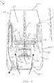
- FIG. 2 An example of a machine 1 for processing a liquid food substance, such as milk or a milk-based substance, is illustrated in Fig. 2 .
- An example of an arrangement of movable heat evacuating members 50 for such a machine 1 is shown in Fig. 1 .
- the arrangement is shown in Fig. 1 with a plurality of movable members 10, the principle of the invention applies to arrangements with any number of movable members, even to an arrangement with only one movable member.
- Machine 1 has: a container 10 delimiting a cavity 10' for containing the liquid food substance, container 10 can be fitted with a removable lid (not shown) for covering the cavity 10'; an impeller 20 for driving the liquid food substance in the container 10; a motor 30 for driving impeller 20; a motor chamber 40 for containing he motor 30, and optionally further components such as a control unit 35 and/or a thermal conditioner 36 e.g. a heater and/or a cooler; and a means for evacuating heat from motor chamber 40.
- a control unit 35 and/or a thermal conditioner 36 e.g. a heater and/or a cooler
- a means for evacuating heat from motor chamber 40 e.g. a heater and/or a cooler
- the heat evacuation means comprises one or more movable members 50 that are driven by motor 30 and that are configured to circulate air 2a,2b in the motor chamber 40 to evacuate heat therefrom.
- the heat evacuation means may be configured to evacuate heat by the circulated air from motor chamber 40 out of such machine 1 predominantly via one or more passages 40,41,42 separate from cavity 10'.
- a complete air circulation from the air intake 2a to the air outflow 2b is illustrated on the left-hand side of Fig. 2 . Only the air intake 2a is illustrated on the right-hand side of Fig 2 . Such air circulation may of course take place at selected places in motor chamber 40 or substantially in the entire chamber 40.
- the heat evacuation means can be configured so that a ratio of the heat evacuated by such passages 40,41,42 over the heat evacuated by the cavity 10' is greater than 2.5, such as greater than 5, for example greater than 10, e.g. greater than 30.
- Motor chamber 40 can have at least one opening 41,42 for an exchange of air 2a,2b driven by the movable members 50 between chamber 40 and a space 2 outside the chamber 40, e.g. a space 2 outside such machine 1.
- Openings 41,42 or other parts of chamber 40 can be formed as radiators or heat sinks to contribute to the heat evacuation.
- Motor chamber 40 can have one or more air inlet openings 41 for letting air 2a into chamber 40 and one or more air outlet openings 42 for letting air 2b out of chamber 40 when movable members 50 are driven by motor 30.
- openings 41 are located on a machine external bottom face 40' and/or machine external side face(s) 40".
- At least one of the air circulation member(s) 50 may be formed as a wing, blade or vane.
- At least one of the air circulation member(s) 50 may have:
- Air circulation member (s) 50 can be mounted on an axle 31 driven by motor 30, such as on a motor's output shaft or an axle driven thereby.
- the axle may be driven via a transmission by the output shaft such as via a gear transmission e.g. a toothed gear transmission.
- a plurality of air circulation members 50 can be mounted in a loop, e.g. in a circle, such as on a ring or a disc 51, about a rotation axis 31'.
- members 50 are generally evenly distributed along the loop.
- Motor chamber 40 may have a centrally located axis 31' and peripheral sidewall(s) 45, the circulation member(s) 50 being driven by motor 30 in motor chamber 40 about centrally located axis 31', between centrally located axis 31' and sidewall(s) 45, such as at a distance from centrally located axis 31' in the range of 1/4 to 3/4 of the spacing from centrally located axis 31' to sidewall 31' at the level of air circulation member 50, e.g. at a distance in the range of 1/3 to 2/3 of such spacing.
- Motor 30 may drive a drive member 51, such as a coupling member having a general shape of a ring or a disc 51 and/or a coupling member bearing at least one of air circulation member(s) 50, for driving impeller 20 in container 10.
- a drive member 51 such as a coupling member having a general shape of a ring or a disc 51 and/or a coupling member bearing at least one of air circulation member(s) 50, for driving impeller 20 in container 10.
- Drive member 51 can incorporate one or more magnetic elements 52 cooperating with magnetic elements 21 of impeller 20 so as to drive impeller 20 magnetically via a wall 11,12, such as a bottom wall 11 and/or a sidewall 12, of container 10.
- magnetic members 52 drive impeller 20 via a wall 43,44 of chamber 40, such as a platform wall 43 and/or a sidewall 44.
- At least one element 52 of drive member 51 can be:
- Such magnetic field-generating element(s) may include an electromagnet element or a permanent magnet element, e.g. made of at least one of iron, nickel, cobalt, rare earth metals, e.g. lanthanide, and alloys and oxides containing such metals as well as polymers (e.g. plastics) carrying such elements and components.
- an electromagnet element or a permanent magnet element e.g. made of at least one of iron, nickel, cobalt, rare earth metals, e.g. lanthanide, and alloys and oxides containing such metals as well as polymers (e.g. plastics) carrying such elements and components.
- Such ferromagnetic element(s) can be made of at least one of Co, Fe, Fe 2 O 3 , FeOFe 2 O 3 , NiOFe 2 O 3 , CuOFe 2 O 3 , MgO Fe 2 O 3 , Nd 2 Fe 14 B, Mn, Bi, Ni, MnSb, MnOFe 2 O 3 , Y 3 Fe 5 O 12 , CrO 2 , MnAs, Gd, Dy, EuO, Cu 2 MnAl, Cu 2 MnIn, Cu 2 MnSn, Ni 2 MnAl, Ni 2 MnIn, Ni 2 MnSn, Ni 2 MnSb, Ni 2 MnGa, Co 2 MnAl, Co 2 MnSi, Co 2 MnGa, Co 2 MnGe, SmCo 5 , Sm 2 Co 17 , Pd 2 MnAl, Pd 2 MnIn, Pd 2 MnSn, Pd 2 MnSb, Co 2 FeSi, Fe 3
- Machine 1 may include a base 4, e.g. an electrically connected base such as a base connected electrically to the mains via an electric cord, and a receptacle 10a that contains the container 10, e.g. a receptacle 10a having a handle 15.
- Receptacle 10a may be connectable to base 4 for processing the liquid food substance and separable from base 4 for dispensing the food substance upon processing and/or for cleaning receptacle 10a.
- Base 4 may contain motor chamber 40.
- Receptacle 10a can be made of passive components 10, base 4 comprising the active components, such as motor 30, a control unit 35 and/or a thermal conditioner 36, typically a heater and/or a cooler, e.g. a radiant or inductive thermal conditioner 36.
- active components such as motor 30, a control unit 35 and/or a thermal conditioner 36, typically a heater and/or a cooler, e.g. a radiant or inductive thermal conditioner 36.
- base 4 forms a nest for receiving receptacle 10a.
- Impeller 20 may have a surface 20' for imparting a mechanical effect to the liquid food substance, such as for mixing it with another fluid, e.g. air.
- Impeller 20 can include a foot 23 for connection to motor 30, e.g. via magnetic elements 21 in foot 23.
- Impeller 20 may have an axle 24 extending towards a mouth 10" of container 10 when impeller 20 is driven by motor 30, e.g. an axle 24 extending to the level of mouth 10", such as an axle 24 that is seizable by a user for removing impeller 20 from container 10.
Description
- The field of the invention pertains to machines for heating a food substance, such as milk or a milk-containing substance. For instance, the machine is provided with an impeller and a heat management arrangement.
- Speciality beverages in which at least a portion is made up of frothed or heated milk are becoming more and more popular. The best-known beverage of this type is a coffee of the cappuccino type. It comprises a liquid portion consisting of coffee topped by a layer of frothed milk which, because of its very much lower density, floats atop the surface of the liquid. In general, preparing one takes time, manipulation operations and cleaning.
- The most customary way of preparing a milk-based froth is to pour the desired amount of milk into the container, immerse a steam outlet pipe from a coffee machine in the container, agitating it up and down to introduce the air needed to form the froth.
- There also exists mechanical stirring appliances which are usually intended for domestic use for beating froth from more or less viscous food products such as eggs, ice, juices or the like. These appliances are usually ill-suited to froth the microbiologically sensitive liquids such as milk. Regular cleaning of the tank of the appliance needs to be envisaged in order to remove any solid food residue. In addition, heating the milk has a tendency to increase the extent to which cooked or burnt proteins are deposited on and adhere to the surfaces. The existing appliances are not, for the most part, well suited to reducing the encrustation of this solid residue, making cleaning troublesome. These appliances also have a stirring and drive mechanism which is fixed and intrudes into the tank, and this presents several disadvantages: the removal/ refitting time is not insignificant, they have a tendency to become soiled more quickly, they entail additional cost as a result of the multiplicity of components, and the stirring means are difficult to clean.
-
US Patent 6,318,247 relates to an appliance for preparing hot beverages or food with stirring such as hot chocolate, for example. Other devices for stirring food products are described in patent documentsWO 2004/043213 orDE 196 24 648 . Stirring systems with a magnetic engagement type are described in documentsUS 2,932,493 ,DE 1 131 372 ,US 4,537,332 andUS 6,712,497 .DE 89 15 094 relates to a refrigerated pot for dispensing a milk-based beverage.US Patent 3,356,349 discloses a stirring device that has a heated tank, magnetic drive means positioned under the tank for driving a hub located in the middle of the tank. - An improved appliance for preparing froth from a milk-based liquid or milk has been proposed in
WO 2006/050900 ,WO 2008/142154 ,WO 2011/039222 andWO 2011/039224 . The device has: an inner tank for receiving the liquid that is to be frothed, in which a rotatable stirrer is positioned; an outer stand holding the tank; drive and control means which are in a cavity located between the inner tank and the outer stand, and which communicate with a switch and electrical connections located on the outer surface of the stand; and disturbance means to optimise circulation of the milk during frothing. InWO 2010/023313 a steam source is associated with the stirring effect. - More recently, it has been proposed, as described in
WO 2009/074555 andWO 2011/144647 , to provide a coffee machine with this type of milk conditioning tank. - An architecture to favour the evacuation of unwanted heat generated by the operation of electric components of the milk frothing appliance has been disclosed in
PCT/EP16/063668 A US2015/117139 . - It is a preferred object of the present invention to provide a machine for heating a food substance which provides a more reliable heat management configuration.
- The invention thus relates to a machine for processing a liquid food substance, such as milk or a milk-based substance. The liquid food substance can be aqueous, e.g. containing coffee and/or chocolate and/or cacao.
- The machine may be a standalone machine, e.g. directly pluggable to the mains via an electric cord, or may be integrated in a food processor arranged to process other food items or to carry out different food conditioning processes, the food processor itself being generally pluggable to the mains via an electric cord whereas the machine is a sub-part of the food processor. Such a food processor may be a beverage maker, such as a coffee maker, e.g. a beverage maker configured to prepare a beverage (such as coffee) from an ingredient capsule.
- The machine of the invention may advantageously be configured to froth and/or heat milk and optionally be associated, as a standalone machine or as an integrated machine, into a coffee maker. Standalone and integrated associations of milk frothing machines and coffee makers are for example disclosed in
WO 2006/050900 ,WO 2008/142154 ,WO 2009/074555 ,WO 2010/023312 andWO 2010/023313 . - Hence, the machine can be a milk frother which operates by incorporating finely divided gas bubbles, e.g. air bubbles, into milk. When the machine is configured for incorporating gas bubbles into the milk, it may include an operating mode without incorporation of gas bubbles.
- The machine of the invention comprises the features of claim 1.
- The container may have a side wall and a bottom wall for delimiting its cavity.
- The container may have a lid to cover the cavity, e.g. as taught in
WO 2008/142154 . - The container can be generally cup-shaped or bowl-shaped or cylinder-shaped, the sidewall being generally upright and the bottom wall being generally flat or curved.
- The container can be provided with a thermally insulating outside material and/or with a handle, for seizure and optional displacement of the container by a human hand. Such a configuration is particularly advantageous when the food is processed at a higher temperature exceeding e.g. 50°C or below 10°C.
- The heat evacuation means comprises one or more movable members that are driven by the motor and that are configured to circulate air in the motor chamber to evacuate heat therefrom.
- For instance, the heat evacuation means is configured to evacuate heat by the circulated air from the motor chamber out of such machine predominantly via one or more passages separate from the cavity. The heat evacuation means can be configured so that a ratio of the heat evacuated by the passages over the heat evacuated by the cavity is greater than 2.5, such as greater than 5, for example greater than 10, e.g. greater than 30.
- By providing a preferential heat evacuation path to minimise a transfer of such heat into the container, the temperature in the container originates mainly from the thermal conditioner (if any) and is not or only insignificantly influenced by the unwanted heat generated within the motor chamber, e.g. generated by the motor and/or other electrical devices. Indeed such unwanted heat is predominantly evacuated by the heat evacuation means to outside the machine without passing via the container.
- It follows that the same motor drives on the one hand the machine's impeller and on the other hand the movable members of the heat evacuation means. Hence, the action of the heat evacuation means can be easily arranged to follow an increase or decrease of the action of the motor and thus an increase or decrease of power consumed by the motor.
- The heat evacuation means may include a further arrangement for evacuating heat, e.g. as disclosed in
PCT/EP16/063668 - The machine can have a heater for heating the liquid food substance.
- The machine can include a control unit for controlling the processing of the liquid food substance, such as for controlling the motor of the impeller. The control unit may be used to control the thermal conditioner, e.g. heater and/or cooler, when present.
- For example, the control unit is configured to control the heater for:
- carrying out different heating profiles over time and/or for carrying out one or more heating profiles of constant or variable heating; and/or
- disabling the heater and optionally activating a cooler (if present) for a constant or variable cooling of the liquid food substance.
- The motor chamber has at least one opening for an exchange of air driven by the movable member(s) between the chamber and a space outside the chamber, e.g. a space outside such machine.
- The motor chamber has one or more air inlet openings for letting air into the chamber and one or more air outlet openings for letting air out of the chamber when the one or more movable members are driven by the motor. Such openings can be located on a machine external bottom face and/or machine external side face(s).
- Such openings or other parts of the motor chamber can be formed as a radiator or a heat sink to contribute to the evacuation of heat from the chamber.
- At least one of the air circulation member(s) can be formed as a wing, blade or vane.
- At least one of the air circulation member (s) may have:
- a generally arched or curved shape, such as the general shape of an angular section of a cylindrical, conical, spherical, elliptoidal, helicoidal shape; and/or
- a generally straight shape formed of a single planar section or a plurality of angled planar sections, optionally at least one planar section (s), e.g. all planar sections, having a (non-zero) angle relative to a direction of motion of the circulation member.
- The air circulation member (s) may be mounted on an axle driven by the motor, such as on a motor's output shaft or an axle driven thereby, e.g. driven via a transmission by the output shaft such as via a gear transmission e.g. a toothed gear transmission.
- The air circulation member(s) and the impeller may be driven at a same rotational speed by the motor or at different rotational speeds. For instance, a gear arrangement transmits a rotational speed from the motor to the air circulation member (s) at a first transmission ratio and to the impeller at a second transmission ratio different to the first transmission ratio. The first transmission ratio may be greater or smaller than the second transmission ratio. Whether it is greater of smaller and to which extent it is greater or smaller, may be based on the desired rotational speed of the impeller in the container (e.g. depending on the shape of the impeller and the desired result of the liquid food processing) on the one hand and the desired rotational speed of the air circulation member(s) (e.g. depending on the shape, movement path and number of the air circulation member (s) and desired air flow in the motor chamber).
- A plurality of air circulation members can be mounted in a loop, e.g. in a circle, such as on a ring or a disc, about a rotation axis, optionally the air circulation members being generally evenly distributed along the loop.
- For example, the air circulation members are arranged for form a fan driven by the motor.
- The motor chamber may have a generally centrally located axis and peripheral sidewall(s), the air circulation member(s) being driven by the motor in the motor chamber about the centrally located axis, between the centrally located and the sidewalls, such as at a distance from the centrally located axis in the range of 1/4 to 3/4 of the spacing from the centrally located axis to the sidewall at the level of the air circulation member, e.g. at a distance in the range of 1/3 to 2/3 of such spacing.
- The motor may drive a drive member, such as a coupling member having a general shape of a ring or a disc and/or a coupling member bearing at least one of the air circulation member (s), for driving the impeller in the container.
- The drive member can incorporate one or more magnetic elements cooperating with magnetic elements of the impeller so as to drive the impeller magnetically via a wall, such as a bottom wall and/or a sidewall, of the container. For instance, the magnetic members driving the impeller via a wall of the chamber, such as a platform wall and/or a sidewall.
- At least one magnetic element of the drive member may be a magnetic field-generating element that is arranged to be magnetically coupled to a corresponding ferromagnetic element of the impeller.
- At least one magnetic element of the drive member may be a ferromagnetic element that is arranged to be magnetically coupled to a corresponding magnetic field-generating element of the impeller.
- At least one magnetic element of the drive member can be a magnetic field-generating element that is arranged to be magnetically coupled to a corresponding magnetic field-generating element of the impeller.
- Such magnetic field-generating element(s) may include an electromagnet element or a permanent magnet element, e.g. made of at least one of iron, nickel, cobalt, rare earth metals, e.g. lanthanide, and alloys and oxides containing such metals as well as polymers (e.g. plastics) carrying such elements and components.
- Such ferromagnetic element(s) can be made of at least one of Co, Fe, Fe2O3, FeOFe2O3, NiOFe2O3, CuOFe2O3, MgO Fe2O3, Nd2Fe14B, Mn, Bi, Ni, MnSb, MnOFe2O3, Y3Fe5O12, CrO2, MnAs, Gd, Dy, EuO, Cu2MnAl, Cu2MnIn, Cu2MnSn, Ni2MnAl, Ni2MnIn, Ni2MnSn, Ni2MnSb, Ni2MnGa, Co2MnAl, Co2MnSi, Co2MnGa, Co2MnGe, SmCo5, Sm2Co17, Pd2MnAl, Pd2MnIn, Pd2MnSn, Pd2MnSb, Co2FeSi, Fe3Si, Fe2VAl, Mn2VGa and Co2FeGe.
- The magnetic coupling of the impeller, e.g. of a low inertia impeller, can be achieved as taught in
WO 2006/050900 or inWO 2008/142154 . - The magnetic coupling of the impeller, e.g. of a high inertia impeller, may be achieved as taught in
PCT/EP16/063664 - When a high transmission torque is transmitted to the impeller via a magnetic coupling (i.e. a strong coupling), a magnetic uncoupling arrangement may be provided, e.g. as taught in
PCT/EP16/063665 - To facilitate the movement of the impeller, if and when in contact with a container support surface, e.g. a bottom of the container, an arrangement as taught in
PCT/EP16/063666 - Alternatively, the impeller may be driven by the motor via a mechanical transmission extending from the motor chamber into the cavity, such as a mechanical transmission extending from the motor to the impeller for an uninterrupted mechanical transmission between the motor and the impeller.
- The machine of the invention may include a base, e.g. an electrically connected base such as a base connected electrically to the mains via an electric cord, and a receptacle containing the container, e.g. a receptacle having a handle. For instance, the receptacle is connectable to the base for processing the liquid food substance and separable from the base for dispensing the food substance upon processing and/or for cleaning the receptacle.
- In one embodiment, the base may contain the motor chamber. In another embodiment, the motor is included in the receptacle, the base forming an electric connector for powering the motor.
- In an embodiment, the receptacle is made of passive components whereas the base comprises the active components, for example the motor, a control unit and/or a thermal conditioner such as a heater and/or a cooler, e.g. a radiant or inductive thermal conditioner. The base may form a nest for receiving the receptacle.
- The container may be mechanically passive. Hence, beyond the inherent mechanical properties of the materials making its structure for containing the food substance and for being integrated or assembled in the machine, the container may be free of any mechanically active part such as a motor or movement transformation system which may require special care for hygiene or cleaning purposes.
- The container may be electrically passive. Hence, beyond the inherent electric properties of the materials making its structure for containing the food substance and for being integrated or assembled in the machine, the container may be free of any electric active parts such as an electric circuit of discrete or integrated components (e.g. resistors, inductances, transistors,...) that require special care for hygiene or cleaning purposes.
- By providing a container which is mechanically and/or electrically passive (optionally with a lid that is equally passive), it can easily be cleaned, e.g. in a dishwater, without any risk of damaging electric and/or mechanic components.
- The impeller may include a surface for imparting a mechanical effect to the liquid food substance, such as for mixing the liquid food substance with another fluid, e.g. air.
- For example, the impeller has a spring-like structure of the type disclosed in
WO 2006/050900 or inWO 2008/142154 and/or the impeller has a wavy and/or open disc-shaped structure as taught inPCT/EP16/063667 - The impeller can have a foot for being connected to the motor, e.g. via magnetic elements in the foot.
- The impeller can include an axle extending towards a mouth of the container when the impeller is driven by the motor, e.g. an axle extending to the level of the mouth, such as an axle that is seizable by a user for removing the impeller from the container.
- The invention will now be described with reference to the schematic drawings, wherein:
-
Figure 1 is a perspective view of a series of movable members for evacuating heat from a motor chamber of an example of a machine according to the invention; and -
Figure 2 is a cross-sectional view of a machine according to the invention incorporating the movable members shown inFig. 1 . - An example of a machine 1 for processing a liquid food substance, such as milk or a milk-based substance, is illustrated in
Fig. 2 . An example of an arrangement of movableheat evacuating members 50 for such a machine 1 is shown inFig. 1 . Whereas the arrangement is shown inFig. 1 with a plurality ofmovable members 10, the principle of the invention applies to arrangements with any number of movable members, even to an arrangement with only one movable member. - Machine 1 has: a
container 10 delimiting a cavity 10' for containing the liquid food substance,container 10 can be fitted with a removable lid (not shown) for covering the cavity 10'; animpeller 20 for driving the liquid food substance in thecontainer 10; amotor 30 for drivingimpeller 20; amotor chamber 40 for containing he motor 30, and optionally further components such as acontrol unit 35 and/or athermal conditioner 36 e.g. a heater and/or a cooler; and a means for evacuating heat frommotor chamber 40. - The heat evacuation means comprises one or more
movable members 50 that are driven bymotor 30 and that are configured to circulateair motor chamber 40 to evacuate heat therefrom. - The heat evacuation means may be configured to evacuate heat by the circulated air from
motor chamber 40 out of such machine 1 predominantly via one ormore passages - A complete air circulation from the
air intake 2a to theair outflow 2b is illustrated on the left-hand side ofFig. 2 . Only theair intake 2a is illustrated on the right-hand side ofFig 2 . Such air circulation may of course take place at selected places inmotor chamber 40 or substantially in theentire chamber 40. - The heat evacuation means can be configured so that a ratio of the heat evacuated by
such passages -
Motor chamber 40 can have at least oneopening air movable members 50 betweenchamber 40 and aspace 2 outside thechamber 40, e.g. aspace 2 outside such machine 1. -
Openings chamber 40 can be formed as radiators or heat sinks to contribute to the heat evacuation. -
Motor chamber 40 can have one or moreair inlet openings 41 for lettingair 2a intochamber 40 and one or moreair outlet openings 42 for lettingair 2b out ofchamber 40 whenmovable members 50 are driven bymotor 30. For instance,openings 41 are located on a machine external bottom face 40' and/or machine external side face(s) 40". - At least one of the air circulation member(s) 50 may be formed as a wing, blade or vane.
- At least one of the air circulation member(s) 50 may have:
- a generally arched or curved shape, such as the general shape of an angular section of a cylindrical, conical, spherical, elliptoidal, helicoidal shape; and/or
- a generally straight shape formed of a single planar section or a plurality of angled planar sections, optionally at least one planar section(s), e.g. all planar sections, having a (non-zero) angle relative to a direction of motion of the circulation member.
- Air circulation member (s) 50 can be mounted on an
axle 31 driven bymotor 30, such as on a motor's output shaft or an axle driven thereby. The axle may be driven via a transmission by the output shaft such as via a gear transmission e.g. a toothed gear transmission. - As illustrated in the example shown in
Fig. 1 , a plurality ofair circulation members 50 can be mounted in a loop, e.g. in a circle, such as on a ring or adisc 51, about a rotation axis 31'. For instance,members 50 are generally evenly distributed along the loop. -
Motor chamber 40 may have a centrally located axis 31' and peripheral sidewall(s) 45, the circulation member(s) 50 being driven bymotor 30 inmotor chamber 40 about centrally located axis 31', between centrally located axis 31' and sidewall(s) 45, such as at a distance from centrally located axis 31' in the range of 1/4 to 3/4 of the spacing from centrally located axis 31' to sidewall 31' at the level ofair circulation member 50, e.g. at a distance in the range of 1/3 to 2/3 of such spacing. -
Motor 30 may drive adrive member 51, such as a coupling member having a general shape of a ring or adisc 51 and/or a coupling member bearing at least one of air circulation member(s) 50, for drivingimpeller 20 incontainer 10. -
Drive member 51 can incorporate one or moremagnetic elements 52 cooperating withmagnetic elements 21 ofimpeller 20 so as to driveimpeller 20 magnetically via awall bottom wall 11 and/or asidewall 12, ofcontainer 10. For instance,magnetic members 52drive impeller 20 via awall chamber 40, such as aplatform wall 43 and/or asidewall 44. - At least one
element 52 ofdrive member 51 can be: - a magnetic field-generating element that is arranged to be magnetically coupled to a corresponding
ferromagnetic element 21 ofimpeller 20; - a ferromagnetic element that is arranged to be magnetically coupled to a corresponding magnetic field-generating
element 21 ofimpeller 20; or - a magnetic field-generating element that is arranged to be magnetically coupled to a corresponding magnetic field-generating
element 21 ofimpeller 20. - Such magnetic field-generating element(s) may include an electromagnet element or a permanent magnet element, e.g. made of at least one of iron, nickel, cobalt, rare earth metals, e.g. lanthanide, and alloys and oxides containing such metals as well as polymers (e.g. plastics) carrying such elements and components.
- Such ferromagnetic element(s) can be made of at least one of Co, Fe, Fe2O3, FeOFe2O3, NiOFe2O3, CuOFe2O3, MgO Fe2O3, Nd2Fe14B, Mn, Bi, Ni, MnSb, MnOFe2O3, Y3Fe5O12, CrO2, MnAs, Gd, Dy, EuO, Cu2MnAl, Cu2MnIn, Cu2MnSn, Ni2MnAl, Ni2MnIn, Ni2MnSn, Ni2MnSb, Ni2MnGa, Co2MnAl, Co2MnSi, Co2MnGa, Co2MnGe, SmCo5, Sm2Co17, Pd2MnAl, Pd2MnIn, Pd2MnSn, Pd2MnSb, Co2FeSi, Fe3Si, Fe2VAl, Mn2VGa and Co2FeGe.
- Machine 1 may include a base 4, e.g. an electrically connected base such as a base connected electrically to the mains via an electric cord, and a receptacle 10a that contains the
container 10, e.g. a receptacle 10a having ahandle 15. Receptacle 10a may be connectable to base 4 for processing the liquid food substance and separable from base 4 for dispensing the food substance upon processing and/or for cleaning receptacle 10a. - Base 4 may contain
motor chamber 40. - Receptacle 10a can be made of
passive components 10, base 4 comprising the active components, such asmotor 30, acontrol unit 35 and/or athermal conditioner 36, typically a heater and/or a cooler, e.g. a radiant or inductivethermal conditioner 36. - For example, base 4 forms a nest for receiving receptacle 10a.
-
Impeller 20 may have a surface 20' for imparting a mechanical effect to the liquid food substance, such as for mixing it with another fluid, e.g. air. -
Impeller 20 can include afoot 23 for connection tomotor 30, e.g. viamagnetic elements 21 infoot 23. -
Impeller 20 may have anaxle 24 extending towards amouth 10" ofcontainer 10 whenimpeller 20 is driven bymotor 30, e.g. anaxle 24 extending to the level ofmouth 10", such as anaxle 24 that is seizable by a user for removingimpeller 20 fromcontainer 10.
Claims (15)
- A machine (1) for processing a liquid food substance, such as milk or a milk-based substance, comprising:- a container (10) delimiting a cavity (10') for containing said liquid food substance, such as a container provided with a removable lid for covering the cavity;- an impeller (20) for driving said liquid food substance in the container (10);- a motor (30) for driving the impeller (20);- a motor chamber (40) for containing the motor (30), and optionally further components such as a control unit (35) and/or a thermal conditioner (36) e.g. a heater and/or a cooler; and- a means for evacuating heat from the motor chamber,the heat evacuation means comprising one or more movable members (50) that are driven by the motor (30) and that are configured to circulate air (2a,2b) in the motor chamber (40) to evacuate heat therefrom,
the motor chamber (40) having at least one opening (41, 42) for an exchange of air (2a,2b) driven by said one or more movable members (50) between the chamber (40) and a space (2) outside such machine (1),
the heat evacuation means being optionally configured to evacuate heat by the circulated air from the motor chamber out of such machine (1) predominantly via one or more passages (40,41,42) separate from the cavity (10'), the heat evacuation means being for instance configured so that a ratio of the heat evacuated by said passages (40,41,42) over the heat evacuated by the cavity is greater than 2.5, such as greater than 5, for example greater than 10, e.g. greater than 30,
characterised in that the motor chamber (40) has one or more air inlet openings (41) for letting air (2a) into the chamber (40) and one or more air outlet openings (42) for letting air (2b) out of the chamber (40) when said one or more movable members (50) are driven by the motor (30), such openings (41,42) being located either on a machine external bottom face (40') or on a machine external side face (40"). - The machine of claim 1, wherein at least one of the air circulation member(s) (50) is formed as a wing, blade or vane.
- The machine of any preceding claim, wherein at least one of the air circulation member(s) (50) has a generally arched or curved shape, such as the general shape of an angular section of a cylindrical, conical, spherical, elliptoidal, helicoidal shape.
- The machine of any preceding claim, wherein at least one of the air circulation member(s) (50) has a generally straight shape formed of a single planar section or a plurality of angled planar sections, optionally at least one planar section(s), e.g. all planar sections, having a (non-zero) angle relative to a direction of motion of the circulation member.
- The machine of any preceding claim, wherein the one or more air circulation member (s) (50) are mounted on an axle (31) driven by the motor (30), such as on a motor's output shaft or an axle driven thereby, e.g. driven via a transmission by the output shaft such as via a gear transmission e.g. a toothed gear transmission.
- The machine of claim 5, wherein the air circulation member(s) and the impeller (20) are driven at a same rotational speed by the motor (30) or at different rotational speeds.
- The machine of any preceding claim, wherein a plurality of air circulation members (50) are mounted in a loop, e.g. in a circle, such as on a ring or a disc (51), about a rotation axis (31'), optionally the air circulation members (50) being generally evenly distributed along the loop.
- The machine of any preceding claim, wherein the motor chamber (40) has a generally centrally located axis (31') and peripheral sidewall(s) (45), the one or more air circulation members (50) being driven by the motor (30) in the motor chamber (40) about the centrally located axis (31'), between the centrally located axis (31') and the sidewalls (45), such as at a distance from the centrally located axis (31') in the range of 1/4 to 3/4 of the spacing from the centrally located axis (31') to the sidewall (31') at the level of the air circulation member (50), e.g. at a distance in the range of 1/3 to 2/3 of said spacing.
- The machine of any preceding claim, wherein the motor (30) drives a drive member (51), such as a coupling member having a general shape of a ring or a disc (51) and/or a coupling member bearing at least one of said air circulation member(s) (50), for driving the impeller (20) in the container (10).
- The machine of claim 9, wherein the drive member (51) incorporates one or more magnetic elements (52) cooperating with magnetic elements (21) of the impeller (20) so as to drive the impeller (20) magnetically via a wall (11,12), such as a bottom wall (11) and/or a sidewall (12), of the container (10), optionally the magnetic members (52) driving the impeller (20) via a wall (43,44) of the chamber (40), such as a platform wall (43) and/or a sidewall (44).
- The machine of claim 10, wherein:- at least one magnetic element (52) of the drive member (51) is a magnetic field-generating element that is arranged to be magnetically coupled to a corresponding ferromagnetic element (21) of the impeller (20);- at least one magnetic element (52) of the drive member (51) is a ferromagnetic element that is arranged to be magnetically coupled to a corresponding magnetic field-generating element (21) of the impeller (20); or- at least one magnetic element (52) of the drive member (51) is a magnetic field-generating element that is arranged to be magnetically coupled to a corresponding magnetic field-generating element (21) of the impeller (20),optionally:- said magnetic field-generating element(s) comprising an electromagnet element or a permanent magnet element, e.g. made of at least one of iron, nickel, cobalt, rare earth metals, e.g. lanthanide, and alloys and oxides containing such metals as well as polymers (e.g. plastics) carrying such elements and components; and/or- said ferromagnetic element (s) is/are made of at least one of Co, Fe, Fe2O3, FeOFe2O3, NiOFe2O3, CuOFe2O3, MgO Fe2O3, Nd2Fe14B, Mn, Bi, Ni, MnSb, MnOFe2O3, Y3Fe5O12, CrO2, MnAs, Gd, Dy, EuO, Cu2MnAl, Cu2MnIn, Cu2MnSn, Ni2MnAl, Ni2MnIn, Ni2MnSn, Ni2MnSb, Ni2MnGa, Co2MnAl, Co2MnSi, Co2MnGa, Co2MnGe, SmCo5, Sm2Co17, Pd2MnAl, Pd2MnIn, Pd2MnSn, Pd2MnSb, Co2FeSi, Fe3Si, Fe2VAl, Mn2VGa and Co2FeGe.
- The machine of any preceding claim, which comprises:- a base (4), e.g. an electrically connected base such as a base connected electrically to the mains via an electric cord; and- a receptacle (10a) that contains the container (10), e.g. a receptacle (10a) having a handle (15), optionally the receptacle (10a) being connectable to the base for processing the liquid food substance and separable from the base for dispensing the food substance upon processing and/or for cleaning the receptacle (10a).
- The machine of claim 12, wherein the base (4) contains the motor chamber (40).
- The machine of claim 12 or 13, wherein the receptacle (10a) is made of passive components (10) whereas the base comprises active components, for instance the motor (30), a control unit (35) and/or a thermal conditioner (36), such as a heater and/or a cooler, e.g. a radiant or inductive thermal conditioner (36), optionally the base (4) forming a nest for receiving the receptacle (10a).
- The machine of any preceding claim, wherein the impeller (20) comprises one or more of:- a surface (20') for imparting a mechanical effect to the liquid food substance, such as for mixing the liquid food substance with another fluid, e.g. air;- a foot (23) for being connected to the motor, e.g. via magnetic elements (21) in the foot (23).- an axle (24) extending towards a mouth (10") of the container (10) when the impeller (20) is driven by the motor (30), e.g. an axle (24) extending to the level of the mouth, such as an axle that is seizable by a user for removing the impeller from the container.
Applications Claiming Priority (2)
| Application Number | Priority Date | Filing Date | Title |
|---|---|---|---|
| EP16203740 | 2016-12-13 | ||
| PCT/EP2017/082212 WO2018108808A1 (en) | 2016-12-13 | 2017-12-11 | Heat management for food processor |
Publications (2)
| Publication Number | Publication Date |
|---|---|
| EP3554326A1 EP3554326A1 (en) | 2019-10-23 |
| EP3554326B1 true EP3554326B1 (en) | 2021-04-28 |
Family
ID=57590318
Family Applications (1)
| Application Number | Title | Priority Date | Filing Date |
|---|---|---|---|
| EP17822593.4A Active EP3554326B1 (en) | 2016-12-13 | 2017-12-11 | Heat management for food processor |
Country Status (10)
| Country | Link |
|---|---|
| US (1) | US11678772B2 (en) |
| EP (1) | EP3554326B1 (en) |
| JP (1) | JP7203023B2 (en) |
| CN (1) | CN109996479B (en) |
| AU (1) | AU2017375887B2 (en) |
| CA (1) | CA3042148A1 (en) |
| ES (1) | ES2879822T3 (en) |
| PT (1) | PT3554326T (en) |
| RU (1) | RU2757847C2 (en) |
| WO (1) | WO2018108808A1 (en) |
Families Citing this family (15)
| Publication number | Priority date | Publication date | Assignee | Title |
|---|---|---|---|---|
| JP7265123B2 (en) * | 2019-01-22 | 2023-04-26 | タイガー魔法瓶株式会社 | rotary crushing and mixing cooker |
| US20220346603A1 (en) | 2019-07-11 | 2022-11-03 | Société des Produits Nestlé S.A. | Regulation of wisking of a food substance |
| EP3996561A1 (en) | 2019-07-11 | 2022-05-18 | Société des Produits Nestlé S.A. | Handy large processing jug |
| AU2021395337A1 (en) | 2020-12-07 | 2023-05-25 | Société des Produits Nestlé SA | Machine for heating and agitating a liquid food substance with shutdown device |
| JP7411597B2 (en) | 2021-03-08 | 2024-01-11 | 日立グローバルライフソリューションズ株式会社 | beverage manufacturing equipment |
| US11512708B1 (en) * | 2021-06-30 | 2022-11-29 | Hewlett-Packard Development Company, L.P. | Viscous flow fan impellers having wave blades |
| US11647860B1 (en) | 2022-05-13 | 2023-05-16 | Sharkninja Operating Llc | Flavored beverage carbonation system |
| US11751585B1 (en) | 2022-05-13 | 2023-09-12 | Sharkninja Operating Llc | Flavored beverage carbonation system |
| WO2023216231A1 (en) | 2022-05-13 | 2023-11-16 | Sharkninja Operating Llc | Agitator for a carbonation system |
| US11738988B1 (en) | 2022-11-17 | 2023-08-29 | Sharkninja Operating Llc | Ingredient container valve control |
| US11745996B1 (en) | 2022-11-17 | 2023-09-05 | Sharkninja Operating Llc | Ingredient containers for use with beverage dispensers |
| US11634314B1 (en) | 2022-11-17 | 2023-04-25 | Sharkninja Operating Llc | Dosing accuracy |
| US11871867B1 (en) | 2023-03-22 | 2024-01-16 | Sharkninja Operating Llc | Additive container with bottom cover |
| US11925287B1 (en) | 2023-03-22 | 2024-03-12 | Sharkninja Operating Llc | Additive container with inlet tube |
| US11931704B1 (en) | 2023-06-16 | 2024-03-19 | Sharkninja Operating Llc | Carbonation chamber |
Family Cites Families (28)
| Publication number | Priority date | Publication date | Assignee | Title |
|---|---|---|---|---|
| US2932493A (en) | 1957-09-09 | 1960-04-12 | Magic Whirl Dispensers Inc | Beverage mixer |
| DE1131372B (en) | 1960-05-19 | 1962-06-14 | Siemens Elektrogeraete Gmbh | Kitchen machine |
| US3356349A (en) | 1966-04-14 | 1967-12-05 | Westinghouse Electric Corp | Range stirring apparatus |
| US3493214A (en) * | 1968-03-25 | 1970-02-03 | Oster Mfg Co John | Electric blender |
| US4537332A (en) | 1982-09-30 | 1985-08-27 | Jet Spray Corp. | Beverage dispenser with improved in-bowl whipper |
| JPS63202236U (en) * | 1987-06-18 | 1988-12-27 | ||
| DE8915094U1 (en) | 1989-12-20 | 1990-02-08 | Spielvogel, Peter, 1000 Berlin, De | |
| US5273358A (en) * | 1992-04-13 | 1993-12-28 | Vita-Mix Corporation | Quiet and efficient motor cooling fan assembly for a blender |
| DE19624648A1 (en) | 1996-06-20 | 1998-01-02 | Bosch Siemens Hausgeraete | Special cooking pot for cooking plate-simmering unit |
| US6318247B1 (en) | 1998-04-02 | 2001-11-20 | Sunbeam Products, Inc. | Appliance for preparation of heated and stirred beverages and foods |
| US6793167B2 (en) | 1999-01-12 | 2004-09-21 | Island Oasis Cocktail Company, Inc. | Food processing apparatus including magnetic drive |
| US6499873B1 (en) * | 2000-11-24 | 2002-12-31 | Quality & Strength Inc. | Fruit/vegetable blender |
| AU2002316157A1 (en) | 2001-05-22 | 2002-12-09 | Shurflo Pump Manufacturing Company, Inc. | Appliance and an appliance drive unit |
| JP2005177339A (en) | 2003-12-22 | 2005-07-07 | Yasuharu Udo | Multipurpose cooking pot |
| DE202004011552U1 (en) * | 2004-07-23 | 2004-09-30 | Tai, Chun-Yu | A method for insulating the sound effect of a food mixer electric motor has an air flow path over the motor held in an inner housing |
| EP1656866A1 (en) | 2004-11-12 | 2006-05-17 | Nestec S.A. | Device and method for the preparation of froth from a liquid milk-based food product |
| US7942570B2 (en) * | 2006-10-31 | 2011-05-17 | Hamilton Beach Brands, Inc. | Blender for blending foodstuff |
| WO2008142154A1 (en) | 2007-05-23 | 2008-11-27 | Nestec S.A. | Appliance for conditioning a milk-based liquid |
| EP2070454B1 (en) | 2007-12-12 | 2015-07-15 | Nestec S.A. | Beverage production machines comprising a plurality of core units |
| PT2341806E (en) | 2008-09-01 | 2013-02-27 | Nestec Sa | Appliance for conditioning a milk-based liquid |
| EP2341805B1 (en) * | 2008-09-01 | 2012-06-20 | Nestec S.A. | Appliance for fine steam-frothing a milk-based liquid |
| US20120189754A1 (en) | 2009-09-29 | 2012-07-26 | Nestec S.A. | Arrangement for mixing a flavouring ingredient with a liquid carrier |
| RU2560312C2 (en) | 2010-05-21 | 2015-08-20 | Нестек С.А. | Device for food product processing with remote control |
| US8480292B2 (en) | 2010-06-01 | 2013-07-09 | Boris Dushine | Systems, apparatus and methods to reconstitute dehydrated drinks |
| US9656227B2 (en) * | 2013-02-27 | 2017-05-23 | Whirlpool Corporation | Food blending appliance with wiper assembly |
| US20150117139A1 (en) | 2013-10-25 | 2015-04-30 | Whirlpool Corporation | Blender jar assembly |
| JP6394074B2 (en) | 2014-06-03 | 2018-09-26 | タイガー魔法瓶株式会社 | Rotary blade heating cooker |
| JP2016150194A (en) | 2015-02-19 | 2016-08-22 | パナソニックIpマネジメント株式会社 | Blender |
-
2017
- 2017-12-11 AU AU2017375887A patent/AU2017375887B2/en active Active
- 2017-12-11 JP JP2019526592A patent/JP7203023B2/en active Active
- 2017-12-11 CN CN201780072800.6A patent/CN109996479B/en active Active
- 2017-12-11 PT PT178225934T patent/PT3554326T/en unknown
- 2017-12-11 ES ES17822593T patent/ES2879822T3/en active Active
- 2017-12-11 RU RU2019114702A patent/RU2757847C2/en active
- 2017-12-11 EP EP17822593.4A patent/EP3554326B1/en active Active
- 2017-12-11 CA CA3042148A patent/CA3042148A1/en active Pending
- 2017-12-11 WO PCT/EP2017/082212 patent/WO2018108808A1/en unknown
- 2017-12-11 US US16/462,713 patent/US11678772B2/en active Active
Non-Patent Citations (1)
| Title |
|---|
| None * |
Also Published As
| Publication number | Publication date |
|---|---|
| JP7203023B2 (en) | 2023-01-12 |
| ES2879822T3 (en) | 2021-11-23 |
| WO2018108808A1 (en) | 2018-06-21 |
| PT3554326T (en) | 2021-06-22 |
| AU2017375887A1 (en) | 2019-05-02 |
| RU2757847C2 (en) | 2021-10-21 |
| RU2019114702A (en) | 2020-11-16 |
| CN109996479B (en) | 2023-03-14 |
| EP3554326A1 (en) | 2019-10-23 |
| US11678772B2 (en) | 2023-06-20 |
| US20200077841A1 (en) | 2020-03-12 |
| CN109996479A (en) | 2019-07-09 |
| AU2017375887B2 (en) | 2023-11-16 |
| CA3042148A1 (en) | 2018-06-21 |
| RU2019114702A3 (en) | 2021-03-31 |
| JP2020513258A (en) | 2020-05-14 |
Similar Documents
| Publication | Publication Date | Title |
|---|---|---|
| EP3554326B1 (en) | Heat management for food processor | |
| AU2018373696B2 (en) | Controlled heat management for food processor | |
| US20200359822A1 (en) | Adjusted thermal generation for food processing | |
| US10807049B2 (en) | Machine for homogenising a food substance | |
| EP3310224B1 (en) | Removal assistance food processor impeller | |
| EP3310226B1 (en) | Impeller for food processor | |
| EP3554324B1 (en) | Ergonomic whisk for food processing | |
| AU2017375886B2 (en) | High torque magnetic transmission for whisk | |
| EP3310225B1 (en) | Food processor with low friction impeller support |
Legal Events
| Date | Code | Title | Description |
|---|---|---|---|
| STAA | Information on the status of an ep patent application or granted ep patent |
Free format text: STATUS: UNKNOWN |
|
| STAA | Information on the status of an ep patent application or granted ep patent |
Free format text: STATUS: THE INTERNATIONAL PUBLICATION HAS BEEN MADE |
|
| PUAI | Public reference made under article 153(3) epc to a published international application that has entered the european phase |
Free format text: ORIGINAL CODE: 0009012 |
|
| STAA | Information on the status of an ep patent application or granted ep patent |
Free format text: STATUS: REQUEST FOR EXAMINATION WAS MADE |
|
| 17P | Request for examination filed |
Effective date: 20190715 |
|
| AK | Designated contracting states |
Kind code of ref document: A1 Designated state(s): AL AT BE BG CH CY CZ DE DK EE ES FI FR GB GR HR HU IE IS IT LI LT LU LV MC MK MT NL NO PL PT RO RS SE SI SK SM TR |
|
| AX | Request for extension of the european patent |
Extension state: BA ME |
|
| DAV | Request for validation of the european patent (deleted) | ||
| DAX | Request for extension of the european patent (deleted) | ||
| GRAP | Despatch of communication of intention to grant a patent |
Free format text: ORIGINAL CODE: EPIDOSNIGR1 |
|
| STAA | Information on the status of an ep patent application or granted ep patent |
Free format text: STATUS: GRANT OF PATENT IS INTENDED |
|
| INTG | Intention to grant announced |
Effective date: 20201126 |
|
| GRAS | Grant fee paid |
Free format text: ORIGINAL CODE: EPIDOSNIGR3 |
|
| GRAA | (expected) grant |
Free format text: ORIGINAL CODE: 0009210 |
|
| STAA | Information on the status of an ep patent application or granted ep patent |
Free format text: STATUS: THE PATENT HAS BEEN GRANTED |
|
| AK | Designated contracting states |
Kind code of ref document: B1 Designated state(s): AL AT BE BG CH CY CZ DE DK EE ES FI FR GB GR HR HU IE IS IT LI LT LU LV MC MK MT NL NO PL PT RO RS SE SI SK SM TR |
|
| REG | Reference to a national code |
Ref country code: GB Ref legal event code: FG4D |
|
| REG | Reference to a national code |
Ref country code: CH Ref legal event code: EP |
|
| REG | Reference to a national code |
Ref country code: AT Ref legal event code: REF Ref document number: 1386150 Country of ref document: AT Kind code of ref document: T Effective date: 20210515 |
|
| REG | Reference to a national code |
Ref country code: DE Ref legal event code: R096 Ref document number: 602017037756 Country of ref document: DE |
|
| REG | Reference to a national code |
Ref country code: IE Ref legal event code: FG4D |
|
| REG | Reference to a national code |
Ref country code: PT Ref legal event code: SC4A Ref document number: 3554326 Country of ref document: PT Date of ref document: 20210622 Kind code of ref document: T Free format text: AVAILABILITY OF NATIONAL TRANSLATION Effective date: 20210615 |
|
| REG | Reference to a national code |
Ref country code: NL Ref legal event code: FP |
|
| REG | Reference to a national code |
Ref country code: LT Ref legal event code: MG9D |
|
| REG | Reference to a national code |
Ref country code: AT Ref legal event code: MK05 Ref document number: 1386150 Country of ref document: AT Kind code of ref document: T Effective date: 20210428 |
|
| PG25 | Lapsed in a contracting state [announced via postgrant information from national office to epo] |
Ref country code: FI Free format text: LAPSE BECAUSE OF FAILURE TO SUBMIT A TRANSLATION OF THE DESCRIPTION OR TO PAY THE FEE WITHIN THE PRESCRIBED TIME-LIMIT Effective date: 20210428 Ref country code: LT Free format text: LAPSE BECAUSE OF FAILURE TO SUBMIT A TRANSLATION OF THE DESCRIPTION OR TO PAY THE FEE WITHIN THE PRESCRIBED TIME-LIMIT Effective date: 20210428 Ref country code: HR Free format text: LAPSE BECAUSE OF FAILURE TO SUBMIT A TRANSLATION OF THE DESCRIPTION OR TO PAY THE FEE WITHIN THE PRESCRIBED TIME-LIMIT Effective date: 20210428 Ref country code: AT Free format text: LAPSE BECAUSE OF FAILURE TO SUBMIT A TRANSLATION OF THE DESCRIPTION OR TO PAY THE FEE WITHIN THE PRESCRIBED TIME-LIMIT Effective date: 20210428 Ref country code: BG Free format text: LAPSE BECAUSE OF FAILURE TO SUBMIT A TRANSLATION OF THE DESCRIPTION OR TO PAY THE FEE WITHIN THE PRESCRIBED TIME-LIMIT Effective date: 20210728 |
|
| REG | Reference to a national code |
Ref country code: ES Ref legal event code: FG2A Ref document number: 2879822 Country of ref document: ES Kind code of ref document: T3 Effective date: 20211123 |
|
| PG25 | Lapsed in a contracting state [announced via postgrant information from national office to epo] |
Ref country code: NO Free format text: LAPSE BECAUSE OF FAILURE TO SUBMIT A TRANSLATION OF THE DESCRIPTION OR TO PAY THE FEE WITHIN THE PRESCRIBED TIME-LIMIT Effective date: 20210728 Ref country code: LV Free format text: LAPSE BECAUSE OF FAILURE TO SUBMIT A TRANSLATION OF THE DESCRIPTION OR TO PAY THE FEE WITHIN THE PRESCRIBED TIME-LIMIT Effective date: 20210428 Ref country code: PL Free format text: LAPSE BECAUSE OF FAILURE TO SUBMIT A TRANSLATION OF THE DESCRIPTION OR TO PAY THE FEE WITHIN THE PRESCRIBED TIME-LIMIT Effective date: 20210428 Ref country code: RS Free format text: LAPSE BECAUSE OF FAILURE TO SUBMIT A TRANSLATION OF THE DESCRIPTION OR TO PAY THE FEE WITHIN THE PRESCRIBED TIME-LIMIT Effective date: 20210428 Ref country code: SE Free format text: LAPSE BECAUSE OF FAILURE TO SUBMIT A TRANSLATION OF THE DESCRIPTION OR TO PAY THE FEE WITHIN THE PRESCRIBED TIME-LIMIT Effective date: 20210428 Ref country code: GR Free format text: LAPSE BECAUSE OF FAILURE TO SUBMIT A TRANSLATION OF THE DESCRIPTION OR TO PAY THE FEE WITHIN THE PRESCRIBED TIME-LIMIT Effective date: 20210729 Ref country code: IS Free format text: LAPSE BECAUSE OF FAILURE TO SUBMIT A TRANSLATION OF THE DESCRIPTION OR TO PAY THE FEE WITHIN THE PRESCRIBED TIME-LIMIT Effective date: 20210828 |
|
| PG25 | Lapsed in a contracting state [announced via postgrant information from national office to epo] |
Ref country code: SK Free format text: LAPSE BECAUSE OF FAILURE TO SUBMIT A TRANSLATION OF THE DESCRIPTION OR TO PAY THE FEE WITHIN THE PRESCRIBED TIME-LIMIT Effective date: 20210428 Ref country code: SM Free format text: LAPSE BECAUSE OF FAILURE TO SUBMIT A TRANSLATION OF THE DESCRIPTION OR TO PAY THE FEE WITHIN THE PRESCRIBED TIME-LIMIT Effective date: 20210428 Ref country code: CZ Free format text: LAPSE BECAUSE OF FAILURE TO SUBMIT A TRANSLATION OF THE DESCRIPTION OR TO PAY THE FEE WITHIN THE PRESCRIBED TIME-LIMIT Effective date: 20210428 Ref country code: DK Free format text: LAPSE BECAUSE OF FAILURE TO SUBMIT A TRANSLATION OF THE DESCRIPTION OR TO PAY THE FEE WITHIN THE PRESCRIBED TIME-LIMIT Effective date: 20210428 Ref country code: EE Free format text: LAPSE BECAUSE OF FAILURE TO SUBMIT A TRANSLATION OF THE DESCRIPTION OR TO PAY THE FEE WITHIN THE PRESCRIBED TIME-LIMIT Effective date: 20210428 Ref country code: RO Free format text: LAPSE BECAUSE OF FAILURE TO SUBMIT A TRANSLATION OF THE DESCRIPTION OR TO PAY THE FEE WITHIN THE PRESCRIBED TIME-LIMIT Effective date: 20210428 |
|
| REG | Reference to a national code |
Ref country code: DE Ref legal event code: R097 Ref document number: 602017037756 Country of ref document: DE |
|
| PLBE | No opposition filed within time limit |
Free format text: ORIGINAL CODE: 0009261 |
|
| STAA | Information on the status of an ep patent application or granted ep patent |
Free format text: STATUS: NO OPPOSITION FILED WITHIN TIME LIMIT |
|
| 26N | No opposition filed |
Effective date: 20220131 |
|
| PG25 | Lapsed in a contracting state [announced via postgrant information from national office to epo] |
Ref country code: IS Free format text: LAPSE BECAUSE OF FAILURE TO SUBMIT A TRANSLATION OF THE DESCRIPTION OR TO PAY THE FEE WITHIN THE PRESCRIBED TIME-LIMIT Effective date: 20210828 Ref country code: AL Free format text: LAPSE BECAUSE OF FAILURE TO SUBMIT A TRANSLATION OF THE DESCRIPTION OR TO PAY THE FEE WITHIN THE PRESCRIBED TIME-LIMIT Effective date: 20210428 |
|
| PG25 | Lapsed in a contracting state [announced via postgrant information from national office to epo] |
Ref country code: MC Free format text: LAPSE BECAUSE OF FAILURE TO SUBMIT A TRANSLATION OF THE DESCRIPTION OR TO PAY THE FEE WITHIN THE PRESCRIBED TIME-LIMIT Effective date: 20210428 |
|
| REG | Reference to a national code |
Ref country code: BE Ref legal event code: MM Effective date: 20211231 |
|
| PG25 | Lapsed in a contracting state [announced via postgrant information from national office to epo] |
Ref country code: LU Free format text: LAPSE BECAUSE OF NON-PAYMENT OF DUE FEES Effective date: 20211211 Ref country code: IE Free format text: LAPSE BECAUSE OF NON-PAYMENT OF DUE FEES Effective date: 20211211 |
|
| PG25 | Lapsed in a contracting state [announced via postgrant information from national office to epo] |
Ref country code: BE Free format text: LAPSE BECAUSE OF NON-PAYMENT OF DUE FEES Effective date: 20211231 |
|
| PGFP | Annual fee paid to national office [announced via postgrant information from national office to epo] |
Ref country code: ES Payment date: 20230113 Year of fee payment: 6 Ref country code: CH Payment date: 20230101 Year of fee payment: 6 |
|
| PG25 | Lapsed in a contracting state [announced via postgrant information from national office to epo] |
Ref country code: CY Free format text: LAPSE BECAUSE OF FAILURE TO SUBMIT A TRANSLATION OF THE DESCRIPTION OR TO PAY THE FEE WITHIN THE PRESCRIBED TIME-LIMIT Effective date: 20210428 |
|
| P01 | Opt-out of the competence of the unified patent court (upc) registered |
Effective date: 20230527 |
|
| PG25 | Lapsed in a contracting state [announced via postgrant information from national office to epo] |
Ref country code: HU Free format text: LAPSE BECAUSE OF FAILURE TO SUBMIT A TRANSLATION OF THE DESCRIPTION OR TO PAY THE FEE WITHIN THE PRESCRIBED TIME-LIMIT; INVALID AB INITIO Effective date: 20171211 |
|
| PGFP | Annual fee paid to national office [announced via postgrant information from national office to epo] |
Ref country code: NL Payment date: 20231116 Year of fee payment: 7 |
|
| PGFP | Annual fee paid to national office [announced via postgrant information from national office to epo] |
Ref country code: GB Payment date: 20231102 Year of fee payment: 7 |
|
| PGFP | Annual fee paid to national office [announced via postgrant information from national office to epo] |
Ref country code: PT Payment date: 20231209 Year of fee payment: 7 Ref country code: IT Payment date: 20231110 Year of fee payment: 7 Ref country code: FR Payment date: 20231108 Year of fee payment: 7 Ref country code: DE Payment date: 20231031 Year of fee payment: 7 |