EP3554326B1 - Wärmeverwaltung für lebensmittelverarbeiter - Google Patents
Wärmeverwaltung für lebensmittelverarbeiter Download PDFInfo
- Publication number
- EP3554326B1 EP3554326B1 EP17822593.4A EP17822593A EP3554326B1 EP 3554326 B1 EP3554326 B1 EP 3554326B1 EP 17822593 A EP17822593 A EP 17822593A EP 3554326 B1 EP3554326 B1 EP 3554326B1
- Authority
- EP
- European Patent Office
- Prior art keywords
- machine
- motor
- impeller
- air
- container
- Prior art date
- Legal status (The legal status is an assumption and is not a legal conclusion. Google has not performed a legal analysis and makes no representation as to the accuracy of the status listed.)
- Active
Links
Images

Classifications
-
- A—HUMAN NECESSITIES
- A47—FURNITURE; DOMESTIC ARTICLES OR APPLIANCES; COFFEE MILLS; SPICE MILLS; SUCTION CLEANERS IN GENERAL
- A47J—KITCHEN EQUIPMENT; COFFEE MILLS; SPICE MILLS; APPARATUS FOR MAKING BEVERAGES
- A47J43/00—Implements for preparing or holding food, not provided for in other groups of this subclass
- A47J43/04—Machines for domestic use not covered elsewhere, e.g. for grinding, mixing, stirring, kneading, emulsifying, whipping or beating foodstuffs, e.g. power-driven
- A47J43/07—Parts or details, e.g. mixing tools, whipping tools
- A47J43/08—Driving mechanisms
-
- A—HUMAN NECESSITIES
- A47—FURNITURE; DOMESTIC ARTICLES OR APPLIANCES; COFFEE MILLS; SPICE MILLS; SUCTION CLEANERS IN GENERAL
- A47J—KITCHEN EQUIPMENT; COFFEE MILLS; SPICE MILLS; APPARATUS FOR MAKING BEVERAGES
- A47J43/00—Implements for preparing or holding food, not provided for in other groups of this subclass
- A47J43/04—Machines for domestic use not covered elsewhere, e.g. for grinding, mixing, stirring, kneading, emulsifying, whipping or beating foodstuffs, e.g. power-driven
- A47J43/046—Machines for domestic use not covered elsewhere, e.g. for grinding, mixing, stirring, kneading, emulsifying, whipping or beating foodstuffs, e.g. power-driven with tools driven from the bottom side
- A47J43/0465—Machines for domestic use not covered elsewhere, e.g. for grinding, mixing, stirring, kneading, emulsifying, whipping or beating foodstuffs, e.g. power-driven with tools driven from the bottom side with magnetic drive
-
- A—HUMAN NECESSITIES
- A47—FURNITURE; DOMESTIC ARTICLES OR APPLIANCES; COFFEE MILLS; SPICE MILLS; SUCTION CLEANERS IN GENERAL
- A47J—KITCHEN EQUIPMENT; COFFEE MILLS; SPICE MILLS; APPARATUS FOR MAKING BEVERAGES
- A47J43/00—Implements for preparing or holding food, not provided for in other groups of this subclass
- A47J43/04—Machines for domestic use not covered elsewhere, e.g. for grinding, mixing, stirring, kneading, emulsifying, whipping or beating foodstuffs, e.g. power-driven
- A47J43/07—Parts or details, e.g. mixing tools, whipping tools
- A47J43/08—Driving mechanisms
- A47J43/085—Driving mechanisms for machines with tools driven from the lower side
-
- B—PERFORMING OPERATIONS; TRANSPORTING
- B01—PHYSICAL OR CHEMICAL PROCESSES OR APPARATUS IN GENERAL
- B01F—MIXING, e.g. DISSOLVING, EMULSIFYING OR DISPERSING
- B01F33/00—Other mixers; Mixing plants; Combinations of mixers
- B01F33/45—Magnetic mixers; Mixers with magnetically driven stirrers
- B01F33/453—Magnetic mixers; Mixers with magnetically driven stirrers using supported or suspended stirring elements
-
- B—PERFORMING OPERATIONS; TRANSPORTING
- B01—PHYSICAL OR CHEMICAL PROCESSES OR APPARATUS IN GENERAL
- B01F—MIXING, e.g. DISSOLVING, EMULSIFYING OR DISPERSING
- B01F2101/00—Mixing characterised by the nature of the mixed materials or by the application field
- B01F2101/06—Mixing of food ingredients
- B01F2101/07—Mixing ingredients into milk or cream, e.g. aerating
Definitions
- the field of the invention pertains to machines for heating a food substance, such as milk or a milk-containing substance.
- the machine is provided with an impeller and a heat management arrangement.
- the best-known beverage of this type is a coffee of the cappuccino type. It comprises a liquid portion consisting of coffee topped by a layer of frothed milk which, because of its very much lower density, floats atop the surface of the liquid. In general, preparing one takes time, manipulation operations and cleaning.
- the most customary way of preparing a milk-based froth is to pour the desired amount of milk into the container, immerse a steam outlet pipe from a coffee machine in the container, agitating it up and down to introduce the air needed to form the froth.
- US Patent 6,318,247 relates to an appliance for preparing hot beverages or food with stirring such as hot chocolate, for example.
- Other devices for stirring food products are described in patent documents WO 2004/043213 or DE 196 24 648 .
- Stirring systems with a magnetic engagement type are described in documents US 2,932,493 , DE 1 131 372 , US 4,537,332 and US 6,712,497 .
- DE 89 15 094 relates to a refrigerated pot for dispensing a milk-based beverage.
- US Patent 3,356,349 discloses a stirring device that has a heated tank, magnetic drive means positioned under the tank for driving a hub located in the middle of the tank.
- the device has: an inner tank for receiving the liquid that is to be frothed, in which a rotatable stirrer is positioned; an outer stand holding the tank; drive and control means which are in a cavity located between the inner tank and the outer stand, and which communicate with a switch and electrical connections located on the outer surface of the stand; and disturbance means to optimise circulation of the milk during frothing.
- a steam source is associated with the stirring effect.
- the invention thus relates to a machine for processing a liquid food substance, such as milk or a milk-based substance.
- the liquid food substance can be aqueous, e.g. containing coffee and/or chocolate and/or cacao.
- the machine may be a standalone machine, e.g. directly pluggable to the mains via an electric cord, or may be integrated in a food processor arranged to process other food items or to carry out different food conditioning processes, the food processor itself being generally pluggable to the mains via an electric cord whereas the machine is a sub-part of the food processor.
- a food processor may be a beverage maker, such as a coffee maker, e.g. a beverage maker configured to prepare a beverage (such as coffee) from an ingredient capsule.
- the machine of the invention may advantageously be configured to froth and/or heat milk and optionally be associated, as a standalone machine or as an integrated machine, into a coffee maker.
- Standalone and integrated associations of milk frothing machines and coffee makers are for example disclosed in WO 2006/050900 , WO 2008/142154 , WO 2009/074555 , WO 2010/023312 and WO 2010/023313 .
- the machine can be a milk frother which operates by incorporating finely divided gas bubbles, e.g. air bubbles, into milk.
- gas bubbles e.g. air bubbles
- the machine When the machine is configured for incorporating gas bubbles into the milk, it may include an operating mode without incorporation of gas bubbles.
- the machine of the invention comprises the features of claim 1.
- the container may have a side wall and a bottom wall for delimiting its cavity.
- the container may have a lid to cover the cavity, e.g. as taught in WO 2008/142154 .
- the container can be generally cup-shaped or bowl-shaped or cylinder-shaped, the sidewall being generally upright and the bottom wall being generally flat or curved.
- the container can be provided with a thermally insulating outside material and/or with a handle, for seizure and optional displacement of the container by a human hand.
- a thermally insulating outside material and/or with a handle, for seizure and optional displacement of the container by a human hand.
- Such a configuration is particularly advantageous when the food is processed at a higher temperature exceeding e.g. 50°C or below 10°C.
- the heat evacuation means comprises one or more movable members that are driven by the motor and that are configured to circulate air in the motor chamber to evacuate heat therefrom.
- the heat evacuation means is configured to evacuate heat by the circulated air from the motor chamber out of such machine predominantly via one or more passages separate from the cavity.
- the heat evacuation means can be configured so that a ratio of the heat evacuated by the passages over the heat evacuated by the cavity is greater than 2.5, such as greater than 5, for example greater than 10, e.g. greater than 30.
- the temperature in the container originates mainly from the thermal conditioner (if any) and is not or only insignificantly influenced by the unwanted heat generated within the motor chamber, e.g. generated by the motor and/or other electrical devices. Indeed such unwanted heat is predominantly evacuated by the heat evacuation means to outside the machine without passing via the container.
- the same motor drives on the one hand the machine's impeller and on the other hand the movable members of the heat evacuation means.
- the action of the heat evacuation means can be easily arranged to follow an increase or decrease of the action of the motor and thus an increase or decrease of power consumed by the motor.
- the heat evacuation means may include a further arrangement for evacuating heat, e.g. as disclosed in PCT/EP16/063668 .
- the heat evacuation means includes a radiator, a dissipator, e.g. a ventilator, and/or a heat sink.
- the machine can have a heater for heating the liquid food substance.
- the machine can include a control unit for controlling the processing of the liquid food substance, such as for controlling the motor of the impeller.
- the control unit may be used to control the thermal conditioner, e.g. heater and/or cooler, when present.
- control unit is configured to control the heater for:
- the motor chamber has at least one opening for an exchange of air driven by the movable member(s) between the chamber and a space outside the chamber, e.g. a space outside such machine.
- the motor chamber has one or more air inlet openings for letting air into the chamber and one or more air outlet openings for letting air out of the chamber when the one or more movable members are driven by the motor.
- Such openings can be located on a machine external bottom face and/or machine external side face(s).
- Such openings or other parts of the motor chamber can be formed as a radiator or a heat sink to contribute to the evacuation of heat from the chamber.
- At least one of the air circulation member(s) can be formed as a wing, blade or vane.
- At least one of the air circulation member (s) may have:
- the air circulation member (s) may be mounted on an axle driven by the motor, such as on a motor's output shaft or an axle driven thereby, e.g. driven via a transmission by the output shaft such as via a gear transmission e.g. a toothed gear transmission.
- the air circulation member(s) and the impeller may be driven at a same rotational speed by the motor or at different rotational speeds.
- a gear arrangement transmits a rotational speed from the motor to the air circulation member (s) at a first transmission ratio and to the impeller at a second transmission ratio different to the first transmission ratio.
- the first transmission ratio may be greater or smaller than the second transmission ratio. Whether it is greater of smaller and to which extent it is greater or smaller, may be based on the desired rotational speed of the impeller in the container (e.g. depending on the shape of the impeller and the desired result of the liquid food processing) on the one hand and the desired rotational speed of the air circulation member(s) (e.g. depending on the shape, movement path and number of the air circulation member (s) and desired air flow in the motor chamber).
- a plurality of air circulation members can be mounted in a loop, e.g. in a circle, such as on a ring or a disc, about a rotation axis, optionally the air circulation members being generally evenly distributed along the loop.
- the air circulation members are arranged for form a fan driven by the motor.
- the motor chamber may have a generally centrally located axis and peripheral sidewall(s), the air circulation member(s) being driven by the motor in the motor chamber about the centrally located axis, between the centrally located and the sidewalls, such as at a distance from the centrally located axis in the range of 1/4 to 3/4 of the spacing from the centrally located axis to the sidewall at the level of the air circulation member, e.g. at a distance in the range of 1/3 to 2/3 of such spacing.
- the motor may drive a drive member, such as a coupling member having a general shape of a ring or a disc and/or a coupling member bearing at least one of the air circulation member (s), for driving the impeller in the container.
- a drive member such as a coupling member having a general shape of a ring or a disc and/or a coupling member bearing at least one of the air circulation member (s), for driving the impeller in the container.
- the drive member can incorporate one or more magnetic elements cooperating with magnetic elements of the impeller so as to drive the impeller magnetically via a wall, such as a bottom wall and/or a sidewall, of the container.
- a wall such as a bottom wall and/or a sidewall
- the magnetic members driving the impeller via a wall of the chamber, such as a platform wall and/or a sidewall.
- At least one magnetic element of the drive member may be a magnetic field-generating element that is arranged to be magnetically coupled to a corresponding ferromagnetic element of the impeller.
- At least one magnetic element of the drive member may be a ferromagnetic element that is arranged to be magnetically coupled to a corresponding magnetic field-generating element of the impeller.
- At least one magnetic element of the drive member can be a magnetic field-generating element that is arranged to be magnetically coupled to a corresponding magnetic field-generating element of the impeller.
- Such magnetic field-generating element(s) may include an electromagnet element or a permanent magnet element, e.g. made of at least one of iron, nickel, cobalt, rare earth metals, e.g. lanthanide, and alloys and oxides containing such metals as well as polymers (e.g. plastics) carrying such elements and components.
- an electromagnet element or a permanent magnet element e.g. made of at least one of iron, nickel, cobalt, rare earth metals, e.g. lanthanide, and alloys and oxides containing such metals as well as polymers (e.g. plastics) carrying such elements and components.
- Such ferromagnetic element(s) can be made of at least one of Co, Fe, Fe 2 O 3 , FeOFe 2 O 3 , NiOFe 2 O 3 , CuOFe 2 O 3 , MgO Fe 2 O 3 , Nd 2 Fe 14 B, Mn, Bi, Ni, MnSb, MnOFe 2 O 3 , Y 3 Fe 5 O 12 , CrO 2 , MnAs, Gd, Dy, EuO, Cu 2 MnAl, Cu 2 MnIn, Cu 2 MnSn, Ni 2 MnAl, Ni 2 MnIn, Ni 2 MnSn, Ni 2 MnSb, Ni 2 MnGa, Co 2 MnAl, Co 2 MnSi, Co 2 MnGa, Co 2 MnGe, SmCo 5 , Sm 2 Co 17 , Pd 2 MnAl, Pd 2 MnIn, Pd 2 MnSn, Pd 2 MnSb, Co 2 FeSi, Fe 3
- the magnetic coupling of the impeller e.g. of a low inertia impeller, can be achieved as taught in WO 2006/050900 or in WO 2008/142154 .
- the magnetic coupling of the impeller e.g. of a high inertia impeller, may be achieved as taught in PCT/EP16/063664 .
- a magnetic uncoupling arrangement may be provided, e.g. as taught in PCT/EP16/063665 .
- the impeller may be driven by the motor via a mechanical transmission extending from the motor chamber into the cavity, such as a mechanical transmission extending from the motor to the impeller for an uninterrupted mechanical transmission between the motor and the impeller.
- the machine of the invention may include a base, e.g. an electrically connected base such as a base connected electrically to the mains via an electric cord, and a receptacle containing the container, e.g. a receptacle having a handle.
- a base e.g. an electrically connected base such as a base connected electrically to the mains via an electric cord
- a receptacle containing the container e.g. a receptacle having a handle.
- the receptacle is connectable to the base for processing the liquid food substance and separable from the base for dispensing the food substance upon processing and/or for cleaning the receptacle.
- the base may contain the motor chamber.
- the motor is included in the receptacle, the base forming an electric connector for powering the motor.
- the receptacle is made of passive components whereas the base comprises the active components, for example the motor, a control unit and/or a thermal conditioner such as a heater and/or a cooler, e.g. a radiant or inductive thermal conditioner.
- the base may form a nest for receiving the receptacle.
- the container may be mechanically passive. Hence, beyond the inherent mechanical properties of the materials making its structure for containing the food substance and for being integrated or assembled in the machine, the container may be free of any mechanically active part such as a motor or movement transformation system which may require special care for hygiene or cleaning purposes.
- the container may be electrically passive. Hence, beyond the inherent electric properties of the materials making its structure for containing the food substance and for being integrated or assembled in the machine, the container may be free of any electric active parts such as an electric circuit of discrete or integrated components (e.g. resistors, inductances, transistors, etc that require special care for hygiene or cleaning purposes.
- any electric active parts such as an electric circuit of discrete or integrated components (e.g. resistors, inductances, transistors,...) that require special care for hygiene or cleaning purposes.
- a container which is mechanically and/or electrically passive (optionally with a lid that is equally passive), it can easily be cleaned, e.g. in a dishwater, without any risk of damaging electric and/or mechanic components.
- the impeller may include a surface for imparting a mechanical effect to the liquid food substance, such as for mixing the liquid food substance with another fluid, e.g. air.
- the impeller has a spring-like structure of the type disclosed in WO 2006/050900 or in WO 2008/142154 and/or the impeller has a wavy and/or open disc-shaped structure as taught in PCT/EP16/063667 .
- the impeller can have a foot for being connected to the motor, e.g. via magnetic elements in the foot.
- the impeller can include an axle extending towards a mouth of the container when the impeller is driven by the motor, e.g. an axle extending to the level of the mouth, such as an axle that is seizable by a user for removing the impeller from the container.
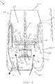
- FIG. 2 An example of a machine 1 for processing a liquid food substance, such as milk or a milk-based substance, is illustrated in Fig. 2 .
- An example of an arrangement of movable heat evacuating members 50 for such a machine 1 is shown in Fig. 1 .
- the arrangement is shown in Fig. 1 with a plurality of movable members 10, the principle of the invention applies to arrangements with any number of movable members, even to an arrangement with only one movable member.
- Machine 1 has: a container 10 delimiting a cavity 10' for containing the liquid food substance, container 10 can be fitted with a removable lid (not shown) for covering the cavity 10'; an impeller 20 for driving the liquid food substance in the container 10; a motor 30 for driving impeller 20; a motor chamber 40 for containing he motor 30, and optionally further components such as a control unit 35 and/or a thermal conditioner 36 e.g. a heater and/or a cooler; and a means for evacuating heat from motor chamber 40.
- a control unit 35 and/or a thermal conditioner 36 e.g. a heater and/or a cooler
- a means for evacuating heat from motor chamber 40 e.g. a heater and/or a cooler
- the heat evacuation means comprises one or more movable members 50 that are driven by motor 30 and that are configured to circulate air 2a,2b in the motor chamber 40 to evacuate heat therefrom.
- the heat evacuation means may be configured to evacuate heat by the circulated air from motor chamber 40 out of such machine 1 predominantly via one or more passages 40,41,42 separate from cavity 10'.
- a complete air circulation from the air intake 2a to the air outflow 2b is illustrated on the left-hand side of Fig. 2 . Only the air intake 2a is illustrated on the right-hand side of Fig 2 . Such air circulation may of course take place at selected places in motor chamber 40 or substantially in the entire chamber 40.
- the heat evacuation means can be configured so that a ratio of the heat evacuated by such passages 40,41,42 over the heat evacuated by the cavity 10' is greater than 2.5, such as greater than 5, for example greater than 10, e.g. greater than 30.
- Motor chamber 40 can have at least one opening 41,42 for an exchange of air 2a,2b driven by the movable members 50 between chamber 40 and a space 2 outside the chamber 40, e.g. a space 2 outside such machine 1.
- Openings 41,42 or other parts of chamber 40 can be formed as radiators or heat sinks to contribute to the heat evacuation.
- Motor chamber 40 can have one or more air inlet openings 41 for letting air 2a into chamber 40 and one or more air outlet openings 42 for letting air 2b out of chamber 40 when movable members 50 are driven by motor 30.
- openings 41 are located on a machine external bottom face 40' and/or machine external side face(s) 40".
- At least one of the air circulation member(s) 50 may be formed as a wing, blade or vane.
- At least one of the air circulation member(s) 50 may have:
- Air circulation member (s) 50 can be mounted on an axle 31 driven by motor 30, such as on a motor's output shaft or an axle driven thereby.
- the axle may be driven via a transmission by the output shaft such as via a gear transmission e.g. a toothed gear transmission.
- a plurality of air circulation members 50 can be mounted in a loop, e.g. in a circle, such as on a ring or a disc 51, about a rotation axis 31'.
- members 50 are generally evenly distributed along the loop.
- Motor chamber 40 may have a centrally located axis 31' and peripheral sidewall(s) 45, the circulation member(s) 50 being driven by motor 30 in motor chamber 40 about centrally located axis 31', between centrally located axis 31' and sidewall(s) 45, such as at a distance from centrally located axis 31' in the range of 1/4 to 3/4 of the spacing from centrally located axis 31' to sidewall 31' at the level of air circulation member 50, e.g. at a distance in the range of 1/3 to 2/3 of such spacing.
- Motor 30 may drive a drive member 51, such as a coupling member having a general shape of a ring or a disc 51 and/or a coupling member bearing at least one of air circulation member(s) 50, for driving impeller 20 in container 10.
- a drive member 51 such as a coupling member having a general shape of a ring or a disc 51 and/or a coupling member bearing at least one of air circulation member(s) 50, for driving impeller 20 in container 10.
- Drive member 51 can incorporate one or more magnetic elements 52 cooperating with magnetic elements 21 of impeller 20 so as to drive impeller 20 magnetically via a wall 11,12, such as a bottom wall 11 and/or a sidewall 12, of container 10.
- magnetic members 52 drive impeller 20 via a wall 43,44 of chamber 40, such as a platform wall 43 and/or a sidewall 44.
- At least one element 52 of drive member 51 can be:
- Such magnetic field-generating element(s) may include an electromagnet element or a permanent magnet element, e.g. made of at least one of iron, nickel, cobalt, rare earth metals, e.g. lanthanide, and alloys and oxides containing such metals as well as polymers (e.g. plastics) carrying such elements and components.
- an electromagnet element or a permanent magnet element e.g. made of at least one of iron, nickel, cobalt, rare earth metals, e.g. lanthanide, and alloys and oxides containing such metals as well as polymers (e.g. plastics) carrying such elements and components.
- Such ferromagnetic element(s) can be made of at least one of Co, Fe, Fe 2 O 3 , FeOFe 2 O 3 , NiOFe 2 O 3 , CuOFe 2 O 3 , MgO Fe 2 O 3 , Nd 2 Fe 14 B, Mn, Bi, Ni, MnSb, MnOFe 2 O 3 , Y 3 Fe 5 O 12 , CrO 2 , MnAs, Gd, Dy, EuO, Cu 2 MnAl, Cu 2 MnIn, Cu 2 MnSn, Ni 2 MnAl, Ni 2 MnIn, Ni 2 MnSn, Ni 2 MnSb, Ni 2 MnGa, Co 2 MnAl, Co 2 MnSi, Co 2 MnGa, Co 2 MnGe, SmCo 5 , Sm 2 Co 17 , Pd 2 MnAl, Pd 2 MnIn, Pd 2 MnSn, Pd 2 MnSb, Co 2 FeSi, Fe 3
- Machine 1 may include a base 4, e.g. an electrically connected base such as a base connected electrically to the mains via an electric cord, and a receptacle 10a that contains the container 10, e.g. a receptacle 10a having a handle 15.
- Receptacle 10a may be connectable to base 4 for processing the liquid food substance and separable from base 4 for dispensing the food substance upon processing and/or for cleaning receptacle 10a.
- Base 4 may contain motor chamber 40.
- Receptacle 10a can be made of passive components 10, base 4 comprising the active components, such as motor 30, a control unit 35 and/or a thermal conditioner 36, typically a heater and/or a cooler, e.g. a radiant or inductive thermal conditioner 36.
- active components such as motor 30, a control unit 35 and/or a thermal conditioner 36, typically a heater and/or a cooler, e.g. a radiant or inductive thermal conditioner 36.
- base 4 forms a nest for receiving receptacle 10a.
- Impeller 20 may have a surface 20' for imparting a mechanical effect to the liquid food substance, such as for mixing it with another fluid, e.g. air.
- Impeller 20 can include a foot 23 for connection to motor 30, e.g. via magnetic elements 21 in foot 23.
- Impeller 20 may have an axle 24 extending towards a mouth 10" of container 10 when impeller 20 is driven by motor 30, e.g. an axle 24 extending to the level of mouth 10", such as an axle 24 that is seizable by a user for removing impeller 20 from container 10.
Landscapes
- Engineering & Computer Science (AREA)
- Mechanical Engineering (AREA)
- Food Science & Technology (AREA)
- Chemical & Material Sciences (AREA)
- Chemical Kinetics & Catalysis (AREA)
- Food-Manufacturing Devices (AREA)
- General Preparation And Processing Of Foods (AREA)
- Structures Of Non-Positive Displacement Pumps (AREA)
Claims (15)
- Maschine (1) zum Verarbeiten einer flüssigen Lebensmittelsubstanz, wie Milch oder einer milchbasierten Substanz, umfassend:- einen Behälter (10), der einen Hohlraum (10') zum Aufnehmen der flüssigen Lebensmittelsubstanz umgrenzt, wie einen Behälter, der mit einem abnehmbaren Deckel zum Abdecken des Hohlraums versehen ist;- einen Impellerrührer (20) zum Antreiben der flüssigen Lebensmittelsubstanz in dem Behälter (10);- einen Motor (30) zum Antreiben des Impellerrührers (20);- eine Motorkammer (40) zum Aufnehmen des Motors (30) und wahlweise weiterer Komponenten, wie einer Steuereinheit (35) und/oder eines thermischen Konditionierers (36), z. B. einer Heizung und/oder eines Kühlers; und- ein Mittel zum Abführen von Wärme aus der Motorkammer,wobei das Wärmeabführmittel ein oder mehrere bewegliche Elemente (50) umfasst, die durch den Motor (30) angetrieben werden und dafür konfiguriert sind, Luft (2a, 2b) in der Motorkammer (40) umzuwälzen, um Wärme daraus abzuführen,
wobei die Motorkammer (40) mindestens eine Öffnung (41, 42) für einen durch das eine oder die mehreren beweglichen Elemente (50) angetriebenen Austausch von Luft (2a, 2b) zwischen der Kammer (40) und einem Raum (2) außerhalb der Maschine (1) aufweist,
wobei das Wärmeabführmittel wahlweise dafür konfiguriert ist, mittels der umgewälzten Luft Wärme aus der Motorkammer einer solchen Maschine (1) abzuführen, und zwar vorwiegend durch einen oder mehrere Durchgänge (40, 41, 42), die von dem Hohlraum (10') getrennt sind, wobei das Wärmeabführmittel zum Beispiel derart konfiguriert ist, dass ein Verhältnis der durch die Durchgänge (40, 41, 42) abgeführten Wärme zu der durch den Hohlraum abgeführten Wärme größer als 2,5, wie größer als 5, beispielsweise größer als 10, z. B. größer als 30, ist, dadurch gekennzeichnet, dass die Motorkammer (40) eine oder mehrere Lufteinlassöffnungen (41) zum Einlassen von Luft (2a) in die Kammer (40) und eine oder mehrere Luftauslassöffnungen (42) zum Auslassen von Luft (2b) aus der Kammer (40), wenn das eine oder die mehreren beweglichen Elemente (50) durch den Motor (30) angetrieben werden, aufweist, wobei sich diese Öffnungen (41, 42) entweder an einer unteren Außenfläche (40') der Maschine oder an einer seitlichen Außenfläche (40") der Maschine befinden. - Maschine nach Anspruch 1, wobei mindestens eines des Luftumwälzungselements/der Luftumwälzungselemente (50) als Flügel, Schaufel oder Blatt gebildet ist.
- Maschine nach einem der vorstehenden Ansprüche, wobei mindestens eines des Luftumwälzungselements/der Luftumwälzungselemente (50) eine im Allgemeinen gewölbte oder gekrümmte Form, wie die allgemeine Form eines Winkelabschnitts einer zylindrischen, konischen, sphärischen, ellipsoiden, helikalen Form, aufweist.
- Maschine nach einem der vorstehenden Ansprüche, wobei mindestens eines des Luftumwälzungselements/der Luftumwälzungselemente (50) eine im Allgemeinen gerade Form aufweist, die aus einem einzelnen ebenen Abschnitt oder einer Vielzahl von abgewinkelten ebenen Abschnitten gebildet ist, wobei wahlweise mindestens ein ebener Abschnitt oder Abschnitte, z. B. alle ebenen Abschnitte, einen (von null verschiedenen) Winkel relativ zu einer Bewegungsrichtung des Luftumwälzungselements aufweist/aufweisen.
- Maschine nach einem der vorstehenden Ansprüche, wobei das eine oder die mehreren Luftumwälzungselement(e) (50) auf einer Achswelle (31), die durch den Motor (30) angetrieben wird, wie auf einer Abtriebswelle eines Motors oder einer Achswelle, die dadurch angetrieben wird, z. B. über ein Getriebe mittels der Abtriebswelle angetrieben wird, wie über ein Rädergetriebe, z. B. ein Zahnradgetriebe, montiert ist/sind.
- Maschine nach Anspruch 5, wobei das/die Luftumwälzungselement(e) und der Impellerrührer (20) mit einer gleichen Drehzahl durch den Motor (30) oder mit unterschiedlichen Drehzahlen angetrieben werden.
- Maschine nach einem der vorstehenden Ansprüche, wobei eine Vielzahl von Luftumwälzungselementen (50) in einer geschlossenen Kurve, z. B. im Kreis, wie auf einem Ring oder einer Scheibe (51), um eine Drehachse (31') montiert ist, wobei wahlweise die Luftumwälzungselemente (50) im Allgemeinen entlang der geschlossenen Kurve gleichmäßig verteilt sind.
- Maschine nach einem der vorstehenden Ansprüche, wobei die Motorkammer (40) eine im Allgemeinen zentral angeordnete Achse (31') und eine oder mehrere periphere Seitenwände (45) aufweist, wobei das eine oder die mehreren Luftumwälzungselemente (50) durch den Motor (30) in der Motorkammer (40) um die zentral angeordnete Achse (31') angetrieben werden, und zwar zwischen der zentral angeordneten Achse (31') und den Seitenwänden (45), wie in einer Entfernung von der zentral angeordneten Achse (31') im Bereich von 1/4 bis 3/4 des Abstands von der zentral angeordneten Achse (31') zu der Seitenwand (31') auf der Ebene des Luftumwälzungselements (50), z. B. in einer Entfernung im Bereich von 1/3 bis 2/3 des Abstands.
- Maschine nach einem der vorstehenden Ansprüche, wobei der Motor (30) ein Antriebselement (51) antreibt, wie ein Kopplungselement, das eine allgemeine Form eines Rings oder einer Scheibe (51) aufweist, und/oder ein Kopplungselement, das mindestens eines des Luftumwälzungselements/der Luftumwälzungselemente (50) trägt, um den Impellerrührer (20) in dem Behälter (10) anzutreiben.
- Maschine nach Anspruch 9, wobei das Antriebselement (51) ein oder mehrere magnetische Elemente (52) integriert, die mit magnetischen Elementen (21) des Impellerrührers (20) zusammenwirken, um den Impellerrührer (20) magnetisch durch eine Wand (11, 12), wie eine Bodenwand (11) und/oder eine Seitenwand (12), des Behälters (10), anzutreiben, wobei wahlweise die magnetischen Elemente (52) den Impellerrührer (20) durch eine Wand (43, 44) der Kammer (40), wie eine Zwischenbodenwand (43) und/oder eine Seitenwand (44), antreiben.
- Maschine nach Anspruch 10, wobei:- mindestens ein magnetisches Element (52) des Antriebselements (51) ein Magnetfelderzeugungselement ist, das dafür eingerichtet ist, mit einem entsprechenden ferromagnetischen Element (21) des Impellerrührers (20) magnetisch gekoppelt zu werden;- mindestens ein magnetisches Element (52) des Antriebselements (51) ein ferromagnetisches Element ist, das dafür eingerichtet ist, mit einem entsprechenden Magnetfelderzeugungselement (21) des Impellerrührers (20) magnetisch gekoppelt zu werden; oder- mindestens ein magnetisches Element (52) des Antriebselements (51) ein Magnetfelderzeugungselement ist, das dafür eingerichtet ist, mit einem entsprechenden Magnetfelderzeugungselement (21) des Impellerrührers (20) gekoppelt zu werden,wobei wahlweise:- das Magnetfelderzeugungselement oder die Magnetfelderzeugungselemente ein Elektromagnetelement oder ein Permanentmagnetelement umfasst/umfassen, das z. B. aus mindestens einem von Eisen, Nickel, Kobalt, Seltenerdmetallen, z. B. Lanthanid, und Legierungen und Oxiden, die solche Metalle enthalten, sowie Polymeren (z. B. Kunststoffen), die Träger solcher Elemente und Komponenten sind, besteht; und/oder- das ferromagnetische Element oder die ferromagnetischen Elemente aus mindestens einem von Co, Fe, Fe2O3, FeOFe2O3, NiOFe2O3, CuOFe2O3, MgOFe2O3, Nd2Fe14B, Mn, Bi, Ni, MnSb, MnOFe2O3, Y3Fe5O12, CrO2, MnAs, Gd, Dy, EuO, Cu2MnAl, Cu2MnIn, Cu2MnSn, Ni2MnAl, Ni2MnIn, Ni2MnSn, Ni2MnSb, Ni2MnGa, Co2MnAl, Co2MnSi, Co2MnGa, Co2MnGe, SmCo5, Sm2Co17, Pd2MnAl, Pd2MnIn, Pd2MnSn, Pd2MnSb, Co2FeSi, Fe3Si, Fe2Val, Mn2VGa und Co2FeGe besteht.
- Maschine nach einem der vorstehenden Ansprüche, umfassend:- eine Basis (4), z. B. eine elektrisch verbundene Basis, wie eine Basis, die über ein Stromkabel mit dem Stromversorgungsnetz elektrisch verbunden ist; und- ein Behältnis (10a), das den Behälter (10) enthält, z. B. ein Behältnis (10a) mit einem Griff (15), wobei das Behältnis (10a) wahlweise zum Verarbeiten der flüssigen Lebensmittelsubstanz mit der Basis verbindbar ist und zum Abgeben der Lebensmittelsubstanz nach dem Verarbeiten und/oder zum Reinigen des Behältnisses (10a) von der Basis trennbar ist.
- Maschine nach Anspruch 12, wobei die Basis (4) die Motorkammer (40) enthält.
- Maschine nach Anspruch 12 oder 13, wobei das Behältnis (10a) aus passiven Komponenten (10) besteht, während die Basis aktive Komponenten, zum Beispiel den Motor (30), eine Steuereinheit (35) und/oder einen thermischen Konditionierer (36), wie eine Heizung und/oder einen Kühler, z. B. einen abstrahlenden oder induktiven thermischen Konditionierer (36), umfasst, wobei wahlweise die Basis (4) eine Aufnahme zum Aufnehmen des Behältnisses (10a) bildet.
- Maschine nach einem der vorstehenden Ansprüche, wobei der Impellerrührer (20) eines oder mehrere umfasst von:- einer Oberfläche (20') zum Ausüben einer mechanischen Wirkung auf die flüssige Lebensmittelsubstanz, wie zum Mischen der flüssigen Lebensmittelsubstanz mit einem anderen Fluid, z. B. Luft;- einem Fuß (23) zur Verbindung mit dem Motor, z. B. mittels magnetischer Elemente (21) in dem Fuß (23).- einer Achswelle (24), die sich in Richtung einer Ausgussöffnung (10") des Behälters (10) erstreckt, wenn der Impellerrührer (20) durch den Motor (30) angetrieben wird, z. B. einer Achswelle (24), die sich bis zur Ebene der Ausgussöffnung erstreckt, wie einer Achswelle, die von einem Benutzer zum Entfernen des Impellerrührers aus dem Behälter greifbar ist.
Applications Claiming Priority (2)
| Application Number | Priority Date | Filing Date | Title |
|---|---|---|---|
| EP16203740 | 2016-12-13 | ||
| PCT/EP2017/082212 WO2018108808A1 (en) | 2016-12-13 | 2017-12-11 | Heat management for food processor |
Publications (2)
| Publication Number | Publication Date |
|---|---|
| EP3554326A1 EP3554326A1 (de) | 2019-10-23 |
| EP3554326B1 true EP3554326B1 (de) | 2021-04-28 |
Family
ID=57590318
Family Applications (1)
| Application Number | Title | Priority Date | Filing Date |
|---|---|---|---|
| EP17822593.4A Active EP3554326B1 (de) | 2016-12-13 | 2017-12-11 | Wärmeverwaltung für lebensmittelverarbeiter |
Country Status (10)
| Country | Link |
|---|---|
| US (1) | US11678772B2 (de) |
| EP (1) | EP3554326B1 (de) |
| JP (1) | JP7203023B2 (de) |
| CN (1) | CN109996479B (de) |
| AU (1) | AU2017375887B2 (de) |
| CA (1) | CA3042148A1 (de) |
| ES (1) | ES2879822T3 (de) |
| PT (1) | PT3554326T (de) |
| RU (1) | RU2757847C2 (de) |
| WO (1) | WO2018108808A1 (de) |
Families Citing this family (32)
| Publication number | Priority date | Publication date | Assignee | Title |
|---|---|---|---|---|
| JP7265123B2 (ja) * | 2019-01-22 | 2023-04-26 | タイガー魔法瓶株式会社 | 回転式破砕混合調理器 |
| JP7536853B2 (ja) | 2019-07-11 | 2024-08-20 | ソシエテ・デ・プロデュイ・ネスレ・エス・アー | 使いやすい大量処理ピッチャ |
| CN114072031A (zh) | 2019-07-11 | 2022-02-18 | 雀巢产品有限公司 | 对食物物质的搅拌的调节 |
| CA3196678A1 (en) | 2020-12-07 | 2022-06-16 | Pascal FRENZEL | Machine for heating and agitating a liquid food substance with shutdown device |
| JP7488214B2 (ja) | 2021-03-08 | 2024-05-21 | 日立グローバルライフソリューションズ株式会社 | 飲料製造装置 |
| JP7411597B2 (ja) * | 2021-03-08 | 2024-01-11 | 日立グローバルライフソリューションズ株式会社 | 飲料製造装置 |
| US11512708B1 (en) * | 2021-06-30 | 2022-11-29 | Hewlett-Packard Development Company, L.P. | Viscous flow fan impellers having wave blades |
| US11647860B1 (en) | 2022-05-13 | 2023-05-16 | Sharkninja Operating Llc | Flavored beverage carbonation system |
| US12096880B2 (en) | 2022-05-13 | 2024-09-24 | Sharkninja Operating Llc | Flavorant for beverage carbonation system |
| US11751585B1 (en) | 2022-05-13 | 2023-09-12 | Sharkninja Operating Llc | Flavored beverage carbonation system |
| US12213617B2 (en) | 2022-05-13 | 2025-02-04 | Sharkninja Operating Llc | Flavored beverage carbonation process |
| CA3253404A1 (en) | 2022-05-13 | 2023-11-16 | Sharkninja Operating Llc | AGITATOR FOR CARBONATION SYSTEM |
| US12005404B2 (en) | 2022-08-22 | 2024-06-11 | Sharkninja Operating Llc | Beverage carbonation system flow control |
| US12539500B2 (en) | 2022-08-31 | 2026-02-03 | Sharkninja Operating Llc | Additive containers |
| US11634314B1 (en) | 2022-11-17 | 2023-04-25 | Sharkninja Operating Llc | Dosing accuracy |
| US12103840B2 (en) | 2022-11-17 | 2024-10-01 | Sharkninja Operating Llc | Ingredient container with sealing valve |
| US11745996B1 (en) | 2022-11-17 | 2023-09-05 | Sharkninja Operating Llc | Ingredient containers for use with beverage dispensers |
| US11738988B1 (en) | 2022-11-17 | 2023-08-29 | Sharkninja Operating Llc | Ingredient container valve control |
| US12084334B2 (en) | 2022-11-17 | 2024-09-10 | Sharkninja Operating Llc | Ingredient container |
| EP4637488A1 (de) | 2022-12-21 | 2025-10-29 | Société des Produits Nestlé S.A. | Getränkezubereitung mit rotierendem laufrad |
| USD1091308S1 (en) | 2022-12-23 | 2025-09-02 | Sharkninja Operating Llc | Ingredient container |
| USD1092208S1 (en) | 2022-12-23 | 2025-09-09 | Sharkninja Operating Llc | Cap of ingredient container |
| US12116257B1 (en) | 2023-03-22 | 2024-10-15 | Sharkninja Operating Llc | Adapter for beverage dispenser |
| US11871867B1 (en) | 2023-03-22 | 2024-01-16 | Sharkninja Operating Llc | Additive container with bottom cover |
| US11925287B1 (en) | 2023-03-22 | 2024-03-12 | Sharkninja Operating Llc | Additive container with inlet tube |
| US12005408B1 (en) | 2023-04-14 | 2024-06-11 | Sharkninja Operating Llc | Mixing funnel |
| WO2024254837A1 (en) | 2023-06-16 | 2024-12-19 | Sharkninja Operating Llc | Carbonation mixing nozzles |
| WO2025132742A1 (en) | 2023-12-22 | 2025-06-26 | Societe Des Produits Nestle S.A. | Jug with whisk retainer |
| WO2025132744A1 (en) | 2023-12-22 | 2025-06-26 | Societe Des Produits Nestle S.A. | Machine with whisk retainer |
| WO2025132743A1 (en) * | 2023-12-22 | 2025-06-26 | Societe Des Produits Nestle S.A. | Machine with liquid guard |
| WO2025132751A1 (en) | 2023-12-22 | 2025-06-26 | Societe Des Produits Nestle S.A. | Machine with inclined top face |
| WO2025132739A1 (en) | 2023-12-22 | 2025-06-26 | Societe Des Produits Nestle S.A. | Machine with lid detection |
Family Cites Families (28)
| Publication number | Priority date | Publication date | Assignee | Title |
|---|---|---|---|---|
| US2932493A (en) | 1957-09-09 | 1960-04-12 | Magic Whirl Dispensers Inc | Beverage mixer |
| DE1131372B (de) | 1960-05-19 | 1962-06-14 | Siemens Elektrogeraete Gmbh | Kuechenmaschine |
| US3356349A (en) | 1966-04-14 | 1967-12-05 | Westinghouse Electric Corp | Range stirring apparatus |
| US3493214A (en) * | 1968-03-25 | 1970-02-03 | Oster Mfg Co John | Electric blender |
| US4537332A (en) | 1982-09-30 | 1985-08-27 | Jet Spray Corp. | Beverage dispenser with improved in-bowl whipper |
| JPS63202236U (de) * | 1987-06-18 | 1988-12-27 | ||
| DE8915094U1 (de) | 1989-12-20 | 1990-02-08 | Spielvogel, Peter, 1000 Berlin | Kanne zur Aufnahme von Milchgetränken |
| US5273358A (en) * | 1992-04-13 | 1993-12-28 | Vita-Mix Corporation | Quiet and efficient motor cooling fan assembly for a blender |
| DE19624648A1 (de) | 1996-06-20 | 1998-01-02 | Bosch Siemens Hausgeraete | Spezialtopf für eine Kochfeld-Garungseinheit |
| US6318247B1 (en) | 1998-04-02 | 2001-11-20 | Sunbeam Products, Inc. | Appliance for preparation of heated and stirred beverages and foods |
| US6793167B2 (en) * | 1999-01-12 | 2004-09-21 | Island Oasis Cocktail Company, Inc. | Food processing apparatus including magnetic drive |
| US6499873B1 (en) * | 2000-11-24 | 2002-12-31 | Quality & Strength Inc. | Fruit/vegetable blender |
| WO2002096761A2 (en) | 2001-05-22 | 2002-12-05 | Shurflo Pump Manufacturing Company, Inc. | Appliance and an appliance drive unit |
| JP2005177339A (ja) * | 2003-12-22 | 2005-07-07 | Yasuharu Udo | 多目的調理鍋 |
| DE202004011552U1 (de) * | 2004-07-23 | 2004-09-30 | Tai, Chun-Yu | Schallisolations-Wärmeableitungsstruktur von Fruchts- und Speisenmischungsgerät |
| EP1656866A1 (de) | 2004-11-12 | 2006-05-17 | Nestec S.A. | Vorrichtung und Verfahren zur Zubereitung von Schaum aus einem flüssigen Milchprodukt |
| US7942570B2 (en) * | 2006-10-31 | 2011-05-17 | Hamilton Beach Brands, Inc. | Blender for blending foodstuff |
| RU2476137C2 (ru) | 2007-05-23 | 2013-02-27 | Нестек С.А. | Электроприбор для кондиционирования жидкости на основе молока |
| EP2070454B1 (de) | 2007-12-12 | 2015-07-15 | Nestec S.A. | Modulare Herstellung von Getränkeherstellungsmaschinen |
| CN102137610B (zh) | 2008-09-01 | 2014-09-17 | 雀巢产品技术援助有限公司 | 用于调制奶基液体的器具 |
| CN102137611B (zh) * | 2008-09-01 | 2013-11-13 | 雀巢产品技术援助有限公司 | 用于使奶基液体细蒸汽起泡的器具 |
| EP2482698A1 (de) | 2009-09-29 | 2012-08-08 | Nestec S.A. | Anordnung zum mischen eines geschmackinhaltsstoffes mit einem flüssigen träger |
| PT2571406E (pt) | 2010-05-21 | 2014-06-02 | Nestec Sa | Processador de alimentos controlado remotamente |
| US8480292B2 (en) * | 2010-06-01 | 2013-07-09 | Boris Dushine | Systems, apparatus and methods to reconstitute dehydrated drinks |
| US9656227B2 (en) * | 2013-02-27 | 2017-05-23 | Whirlpool Corporation | Food blending appliance with wiper assembly |
| US20150117139A1 (en) * | 2013-10-25 | 2015-04-30 | Whirlpool Corporation | Blender jar assembly |
| JP6394074B2 (ja) | 2014-06-03 | 2018-09-26 | タイガー魔法瓶株式会社 | 回転刃式加熱調理器 |
| JP2016150194A (ja) * | 2015-02-19 | 2016-08-22 | パナソニックIpマネジメント株式会社 | ブレンダー |
-
2017
- 2017-12-11 RU RU2019114702A patent/RU2757847C2/ru active
- 2017-12-11 PT PT178225934T patent/PT3554326T/pt unknown
- 2017-12-11 WO PCT/EP2017/082212 patent/WO2018108808A1/en not_active Ceased
- 2017-12-11 CA CA3042148A patent/CA3042148A1/en active Pending
- 2017-12-11 ES ES17822593T patent/ES2879822T3/es active Active
- 2017-12-11 AU AU2017375887A patent/AU2017375887B2/en active Active
- 2017-12-11 EP EP17822593.4A patent/EP3554326B1/de active Active
- 2017-12-11 CN CN201780072800.6A patent/CN109996479B/zh active Active
- 2017-12-11 US US16/462,713 patent/US11678772B2/en active Active
- 2017-12-11 JP JP2019526592A patent/JP7203023B2/ja active Active
Non-Patent Citations (1)
| Title |
|---|
| None * |
Also Published As
| Publication number | Publication date |
|---|---|
| US20200077841A1 (en) | 2020-03-12 |
| PT3554326T (pt) | 2021-06-22 |
| RU2757847C2 (ru) | 2021-10-21 |
| WO2018108808A1 (en) | 2018-06-21 |
| US11678772B2 (en) | 2023-06-20 |
| AU2017375887B2 (en) | 2023-11-16 |
| JP7203023B2 (ja) | 2023-01-12 |
| JP2020513258A (ja) | 2020-05-14 |
| CN109996479B (zh) | 2023-03-14 |
| EP3554326A1 (de) | 2019-10-23 |
| CA3042148A1 (en) | 2018-06-21 |
| RU2019114702A3 (de) | 2021-03-31 |
| ES2879822T3 (es) | 2021-11-23 |
| RU2019114702A (ru) | 2020-11-16 |
| CN109996479A (zh) | 2019-07-09 |
| AU2017375887A1 (en) | 2019-05-02 |
Similar Documents
| Publication | Publication Date | Title |
|---|---|---|
| EP3554326B1 (de) | Wärmeverwaltung für lebensmittelverarbeiter | |
| EP3713464B1 (de) | Gesteuerte wärmeverwaltung für lebensmittelverarbeiter | |
| US12070145B2 (en) | Adjusted thermal generation for food processing | |
| EP3310224B1 (de) | Küchenmaschinenlaufrad mit ausbauunterstützung | |
| EP3554324B1 (de) | Ergonomischer rührbesen zur lebensmittelverarbeitung | |
| US10807049B2 (en) | Machine for homogenising a food substance | |
| EP3310226B1 (de) | Laufrad für küchenmaschine | |
| EP3310225B1 (de) | Lebensmittelverarbeiter mit halter für reibungsarmes laufrad | |
| WO2018108807A1 (en) | High torque magnetic transmission for whisk |
Legal Events
| Date | Code | Title | Description |
|---|---|---|---|
| STAA | Information on the status of an ep patent application or granted ep patent |
Free format text: STATUS: UNKNOWN |
|
| STAA | Information on the status of an ep patent application or granted ep patent |
Free format text: STATUS: THE INTERNATIONAL PUBLICATION HAS BEEN MADE |
|
| PUAI | Public reference made under article 153(3) epc to a published international application that has entered the european phase |
Free format text: ORIGINAL CODE: 0009012 |
|
| STAA | Information on the status of an ep patent application or granted ep patent |
Free format text: STATUS: REQUEST FOR EXAMINATION WAS MADE |
|
| 17P | Request for examination filed |
Effective date: 20190715 |
|
| AK | Designated contracting states |
Kind code of ref document: A1 Designated state(s): AL AT BE BG CH CY CZ DE DK EE ES FI FR GB GR HR HU IE IS IT LI LT LU LV MC MK MT NL NO PL PT RO RS SE SI SK SM TR |
|
| AX | Request for extension of the european patent |
Extension state: BA ME |
|
| DAV | Request for validation of the european patent (deleted) | ||
| DAX | Request for extension of the european patent (deleted) | ||
| GRAP | Despatch of communication of intention to grant a patent |
Free format text: ORIGINAL CODE: EPIDOSNIGR1 |
|
| STAA | Information on the status of an ep patent application or granted ep patent |
Free format text: STATUS: GRANT OF PATENT IS INTENDED |
|
| INTG | Intention to grant announced |
Effective date: 20201126 |
|
| GRAS | Grant fee paid |
Free format text: ORIGINAL CODE: EPIDOSNIGR3 |
|
| GRAA | (expected) grant |
Free format text: ORIGINAL CODE: 0009210 |
|
| STAA | Information on the status of an ep patent application or granted ep patent |
Free format text: STATUS: THE PATENT HAS BEEN GRANTED |
|
| AK | Designated contracting states |
Kind code of ref document: B1 Designated state(s): AL AT BE BG CH CY CZ DE DK EE ES FI FR GB GR HR HU IE IS IT LI LT LU LV MC MK MT NL NO PL PT RO RS SE SI SK SM TR |
|
| REG | Reference to a national code |
Ref country code: GB Ref legal event code: FG4D |
|
| REG | Reference to a national code |
Ref country code: CH Ref legal event code: EP |
|
| REG | Reference to a national code |
Ref country code: AT Ref legal event code: REF Ref document number: 1386150 Country of ref document: AT Kind code of ref document: T Effective date: 20210515 |
|
| REG | Reference to a national code |
Ref country code: DE Ref legal event code: R096 Ref document number: 602017037756 Country of ref document: DE |
|
| REG | Reference to a national code |
Ref country code: IE Ref legal event code: FG4D |
|
| REG | Reference to a national code |
Ref country code: PT Ref legal event code: SC4A Ref document number: 3554326 Country of ref document: PT Date of ref document: 20210622 Kind code of ref document: T Free format text: AVAILABILITY OF NATIONAL TRANSLATION Effective date: 20210615 |
|
| REG | Reference to a national code |
Ref country code: NL Ref legal event code: FP |
|
| REG | Reference to a national code |
Ref country code: LT Ref legal event code: MG9D |
|
| REG | Reference to a national code |
Ref country code: AT Ref legal event code: MK05 Ref document number: 1386150 Country of ref document: AT Kind code of ref document: T Effective date: 20210428 |
|
| PG25 | Lapsed in a contracting state [announced via postgrant information from national office to epo] |
Ref country code: FI Free format text: LAPSE BECAUSE OF FAILURE TO SUBMIT A TRANSLATION OF THE DESCRIPTION OR TO PAY THE FEE WITHIN THE PRESCRIBED TIME-LIMIT Effective date: 20210428 Ref country code: LT Free format text: LAPSE BECAUSE OF FAILURE TO SUBMIT A TRANSLATION OF THE DESCRIPTION OR TO PAY THE FEE WITHIN THE PRESCRIBED TIME-LIMIT Effective date: 20210428 Ref country code: HR Free format text: LAPSE BECAUSE OF FAILURE TO SUBMIT A TRANSLATION OF THE DESCRIPTION OR TO PAY THE FEE WITHIN THE PRESCRIBED TIME-LIMIT Effective date: 20210428 Ref country code: AT Free format text: LAPSE BECAUSE OF FAILURE TO SUBMIT A TRANSLATION OF THE DESCRIPTION OR TO PAY THE FEE WITHIN THE PRESCRIBED TIME-LIMIT Effective date: 20210428 Ref country code: BG Free format text: LAPSE BECAUSE OF FAILURE TO SUBMIT A TRANSLATION OF THE DESCRIPTION OR TO PAY THE FEE WITHIN THE PRESCRIBED TIME-LIMIT Effective date: 20210728 |
|
| REG | Reference to a national code |
Ref country code: ES Ref legal event code: FG2A Ref document number: 2879822 Country of ref document: ES Kind code of ref document: T3 Effective date: 20211123 |
|
| PG25 | Lapsed in a contracting state [announced via postgrant information from national office to epo] |
Ref country code: NO Free format text: LAPSE BECAUSE OF FAILURE TO SUBMIT A TRANSLATION OF THE DESCRIPTION OR TO PAY THE FEE WITHIN THE PRESCRIBED TIME-LIMIT Effective date: 20210728 Ref country code: LV Free format text: LAPSE BECAUSE OF FAILURE TO SUBMIT A TRANSLATION OF THE DESCRIPTION OR TO PAY THE FEE WITHIN THE PRESCRIBED TIME-LIMIT Effective date: 20210428 Ref country code: PL Free format text: LAPSE BECAUSE OF FAILURE TO SUBMIT A TRANSLATION OF THE DESCRIPTION OR TO PAY THE FEE WITHIN THE PRESCRIBED TIME-LIMIT Effective date: 20210428 Ref country code: RS Free format text: LAPSE BECAUSE OF FAILURE TO SUBMIT A TRANSLATION OF THE DESCRIPTION OR TO PAY THE FEE WITHIN THE PRESCRIBED TIME-LIMIT Effective date: 20210428 Ref country code: SE Free format text: LAPSE BECAUSE OF FAILURE TO SUBMIT A TRANSLATION OF THE DESCRIPTION OR TO PAY THE FEE WITHIN THE PRESCRIBED TIME-LIMIT Effective date: 20210428 Ref country code: GR Free format text: LAPSE BECAUSE OF FAILURE TO SUBMIT A TRANSLATION OF THE DESCRIPTION OR TO PAY THE FEE WITHIN THE PRESCRIBED TIME-LIMIT Effective date: 20210729 Ref country code: IS Free format text: LAPSE BECAUSE OF FAILURE TO SUBMIT A TRANSLATION OF THE DESCRIPTION OR TO PAY THE FEE WITHIN THE PRESCRIBED TIME-LIMIT Effective date: 20210828 |
|
| PG25 | Lapsed in a contracting state [announced via postgrant information from national office to epo] |
Ref country code: SK Free format text: LAPSE BECAUSE OF FAILURE TO SUBMIT A TRANSLATION OF THE DESCRIPTION OR TO PAY THE FEE WITHIN THE PRESCRIBED TIME-LIMIT Effective date: 20210428 Ref country code: SM Free format text: LAPSE BECAUSE OF FAILURE TO SUBMIT A TRANSLATION OF THE DESCRIPTION OR TO PAY THE FEE WITHIN THE PRESCRIBED TIME-LIMIT Effective date: 20210428 Ref country code: CZ Free format text: LAPSE BECAUSE OF FAILURE TO SUBMIT A TRANSLATION OF THE DESCRIPTION OR TO PAY THE FEE WITHIN THE PRESCRIBED TIME-LIMIT Effective date: 20210428 Ref country code: DK Free format text: LAPSE BECAUSE OF FAILURE TO SUBMIT A TRANSLATION OF THE DESCRIPTION OR TO PAY THE FEE WITHIN THE PRESCRIBED TIME-LIMIT Effective date: 20210428 Ref country code: EE Free format text: LAPSE BECAUSE OF FAILURE TO SUBMIT A TRANSLATION OF THE DESCRIPTION OR TO PAY THE FEE WITHIN THE PRESCRIBED TIME-LIMIT Effective date: 20210428 Ref country code: RO Free format text: LAPSE BECAUSE OF FAILURE TO SUBMIT A TRANSLATION OF THE DESCRIPTION OR TO PAY THE FEE WITHIN THE PRESCRIBED TIME-LIMIT Effective date: 20210428 |
|
| REG | Reference to a national code |
Ref country code: DE Ref legal event code: R097 Ref document number: 602017037756 Country of ref document: DE |
|
| PLBE | No opposition filed within time limit |
Free format text: ORIGINAL CODE: 0009261 |
|
| STAA | Information on the status of an ep patent application or granted ep patent |
Free format text: STATUS: NO OPPOSITION FILED WITHIN TIME LIMIT |
|
| 26N | No opposition filed |
Effective date: 20220131 |
|
| PG25 | Lapsed in a contracting state [announced via postgrant information from national office to epo] |
Ref country code: IS Free format text: LAPSE BECAUSE OF FAILURE TO SUBMIT A TRANSLATION OF THE DESCRIPTION OR TO PAY THE FEE WITHIN THE PRESCRIBED TIME-LIMIT Effective date: 20210828 Ref country code: AL Free format text: LAPSE BECAUSE OF FAILURE TO SUBMIT A TRANSLATION OF THE DESCRIPTION OR TO PAY THE FEE WITHIN THE PRESCRIBED TIME-LIMIT Effective date: 20210428 |
|
| PG25 | Lapsed in a contracting state [announced via postgrant information from national office to epo] |
Ref country code: MC Free format text: LAPSE BECAUSE OF FAILURE TO SUBMIT A TRANSLATION OF THE DESCRIPTION OR TO PAY THE FEE WITHIN THE PRESCRIBED TIME-LIMIT Effective date: 20210428 |
|
| REG | Reference to a national code |
Ref country code: BE Ref legal event code: MM Effective date: 20211231 |
|
| PG25 | Lapsed in a contracting state [announced via postgrant information from national office to epo] |
Ref country code: LU Free format text: LAPSE BECAUSE OF NON-PAYMENT OF DUE FEES Effective date: 20211211 Ref country code: IE Free format text: LAPSE BECAUSE OF NON-PAYMENT OF DUE FEES Effective date: 20211211 |
|
| PG25 | Lapsed in a contracting state [announced via postgrant information from national office to epo] |
Ref country code: BE Free format text: LAPSE BECAUSE OF NON-PAYMENT OF DUE FEES Effective date: 20211231 |
|
| PG25 | Lapsed in a contracting state [announced via postgrant information from national office to epo] |
Ref country code: CY Free format text: LAPSE BECAUSE OF FAILURE TO SUBMIT A TRANSLATION OF THE DESCRIPTION OR TO PAY THE FEE WITHIN THE PRESCRIBED TIME-LIMIT Effective date: 20210428 |
|
| P01 | Opt-out of the competence of the unified patent court (upc) registered |
Effective date: 20230527 |
|
| PG25 | Lapsed in a contracting state [announced via postgrant information from national office to epo] |
Ref country code: HU Free format text: LAPSE BECAUSE OF FAILURE TO SUBMIT A TRANSLATION OF THE DESCRIPTION OR TO PAY THE FEE WITHIN THE PRESCRIBED TIME-LIMIT; INVALID AB INITIO Effective date: 20171211 |
|
| PG25 | Lapsed in a contracting state [announced via postgrant information from national office to epo] |
Ref country code: MK Free format text: LAPSE BECAUSE OF FAILURE TO SUBMIT A TRANSLATION OF THE DESCRIPTION OR TO PAY THE FEE WITHIN THE PRESCRIBED TIME-LIMIT Effective date: 20210428 |
|
| PG25 | Lapsed in a contracting state [announced via postgrant information from national office to epo] |
Ref country code: TR Free format text: LAPSE BECAUSE OF FAILURE TO SUBMIT A TRANSLATION OF THE DESCRIPTION OR TO PAY THE FEE WITHIN THE PRESCRIBED TIME-LIMIT Effective date: 20210428 |
|
| PG25 | Lapsed in a contracting state [announced via postgrant information from national office to epo] |
Ref country code: MT Free format text: LAPSE BECAUSE OF FAILURE TO SUBMIT A TRANSLATION OF THE DESCRIPTION OR TO PAY THE FEE WITHIN THE PRESCRIBED TIME-LIMIT Effective date: 20210428 |
|
| PGFP | Annual fee paid to national office [announced via postgrant information from national office to epo] |
Ref country code: NL Payment date: 20251112 Year of fee payment: 9 |
|
| REG | Reference to a national code |
Ref country code: CH Ref legal event code: U11 Free format text: ST27 STATUS EVENT CODE: U-0-0-U10-U11 (AS PROVIDED BY THE NATIONAL OFFICE) Effective date: 20260101 |
|
| PGFP | Annual fee paid to national office [announced via postgrant information from national office to epo] |
Ref country code: DE Payment date: 20251104 Year of fee payment: 9 |
|
| PGFP | Annual fee paid to national office [announced via postgrant information from national office to epo] |
Ref country code: GB Payment date: 20251030 Year of fee payment: 9 |
|
| PGFP | Annual fee paid to national office [announced via postgrant information from national office to epo] |
Ref country code: PT Payment date: 20251211 Year of fee payment: 9 |
|
| PGFP | Annual fee paid to national office [announced via postgrant information from national office to epo] |
Ref country code: IT Payment date: 20251121 Year of fee payment: 9 |
|
| PGFP | Annual fee paid to national office [announced via postgrant information from national office to epo] |
Ref country code: FR Payment date: 20251110 Year of fee payment: 9 |
|
| PGFP | Annual fee paid to national office [announced via postgrant information from national office to epo] |
Ref country code: ES Payment date: 20260113 Year of fee payment: 9 |
|
| PGFP | Annual fee paid to national office [announced via postgrant information from national office to epo] |
Ref country code: CH Payment date: 20260101 Year of fee payment: 9 |