EP3554318B1 - Kaffeebrühvorrichtung - Google Patents
Kaffeebrühvorrichtung Download PDFInfo
- Publication number
- EP3554318B1 EP3554318B1 EP17880782.2A EP17880782A EP3554318B1 EP 3554318 B1 EP3554318 B1 EP 3554318B1 EP 17880782 A EP17880782 A EP 17880782A EP 3554318 B1 EP3554318 B1 EP 3554318B1
- Authority
- EP
- European Patent Office
- Prior art keywords
- coffee
- lid
- container
- brewer
- cap
- Prior art date
- Legal status (The legal status is an assumption and is not a legal conclusion. Google has not performed a legal analysis and makes no representation as to the accuracy of the status listed.)
- Active
Links
Images


Classifications
-
- A—HUMAN NECESSITIES
- A47—FURNITURE; DOMESTIC ARTICLES OR APPLIANCES; COFFEE MILLS; SPICE MILLS; SUCTION CLEANERS IN GENERAL
- A47J—KITCHEN EQUIPMENT; COFFEE MILLS; SPICE MILLS; APPARATUS FOR MAKING BEVERAGES
- A47J31/00—Apparatus for making beverages
- A47J31/005—Portable or compact beverage making apparatus, e.g. for travelling, for use in automotive vehicles
-
- A—HUMAN NECESSITIES
- A47—FURNITURE; DOMESTIC ARTICLES OR APPLIANCES; COFFEE MILLS; SPICE MILLS; SUCTION CLEANERS IN GENERAL
- A47J—KITCHEN EQUIPMENT; COFFEE MILLS; SPICE MILLS; APPARATUS FOR MAKING BEVERAGES
- A47J31/00—Apparatus for making beverages
- A47J31/06—Filters or strainers for coffee or tea makers ; Holders therefor
- A47J31/0626—Filters or strainers for coffee or tea makers ; Holders therefor with means for securing the filter holder to the beverage container
-
- A—HUMAN NECESSITIES
- A47—FURNITURE; DOMESTIC ARTICLES OR APPLIANCES; COFFEE MILLS; SPICE MILLS; SUCTION CLEANERS IN GENERAL
- A47J—KITCHEN EQUIPMENT; COFFEE MILLS; SPICE MILLS; APPARATUS FOR MAKING BEVERAGES
- A47J31/00—Apparatus for making beverages
- A47J31/06—Filters or strainers for coffee or tea makers ; Holders therefor
- A47J31/0636—Filters or strainers for coffee or tea makers ; Holders therefor suspended from the top of the beverage container so as to remain in contact with the prepared infusion
-
- A—HUMAN NECESSITIES
- A47—FURNITURE; DOMESTIC ARTICLES OR APPLIANCES; COFFEE MILLS; SPICE MILLS; SUCTION CLEANERS IN GENERAL
- A47J—KITCHEN EQUIPMENT; COFFEE MILLS; SPICE MILLS; APPARATUS FOR MAKING BEVERAGES
- A47J31/00—Apparatus for making beverages
- A47J31/14—Coffee or tea-making apparatus with filters placed in or behind pouring spouts
-
- A—HUMAN NECESSITIES
- A47—FURNITURE; DOMESTIC ARTICLES OR APPLIANCES; COFFEE MILLS; SPICE MILLS; SUCTION CLEANERS IN GENERAL
- A47J—KITCHEN EQUIPMENT; COFFEE MILLS; SPICE MILLS; APPARATUS FOR MAKING BEVERAGES
- A47J31/00—Apparatus for making beverages
- A47J31/18—Apparatus in which ground coffee or tea-leaves are immersed in the hot liquid in the beverage container
Definitions
- the present invention concerns a coffee brewer for brewing in particular fresh coffee without supply of energy beyond the requirement for hot water.
- the coffee brewer preferably includes an insulated container with a sealing lid, a filter and an outlet valve.
- the taste and aroma of the coffee is also influenced by how the coffee beans are treated before grinding (including roasting), and also the type of grinding the beans are exposed to that affects the time required for brewing or infusion.
- US 2004/0020368 discloses a device for brewing coffee and espresso beverages, comprising a body connected to a container, a filter, and filtration openings, and a method for brewing beverages using the device.
- EP1260165 A1 also discloses a coffee brewer.
- the present invention concerns a coffee brewer for full-immersion brewing as defined in independent claim 1, said coffee brewer includes a container with a volume, a closed end and an open end.
- a lid includes an inside with an inner area and an outside with for sealing attachment to the open end.
- Outlets and a manually actuated sealed valve open or close a flow path between the container and the outlets.
- a coffee filter is secured to the inside of the lid, in the flow path between the container and the outlets.
- the outlets are located to allow pouring of coffee while actuating the valve, whereby the valve of the coffee brewer can be actuated from a closed position to an open position with the closed end facing up and the container above the lid, without spilling coffee on an operator actuating the valve.
- the container may be insulated.
- the outlets are surrounded by a sleeve protruding as a cylindrical ring from a front portion of the end-cap whereby spillage of coffee onto a hand of an operator when unscrewing the screw cap is prevented.
- the outlets at the front portion of the end-cap are distributed as a plurality individual outlets, whereby the end-cap attenuates the flow of coffee to prevent jets of coffee from the end-cap.
- the outlets at the front portion of the end-cap form discrete arc-shaped openings, and the arcs form a complete circle surrounding a front face of the end-cap.
- the end-cap includes a centrally located cylindrical portion holding an O-ring, and a cylindrical portion with internal threads.
- the coffee brewer may further include a gap between the inner lid surface and a circular, perforated filter holder, forming a cavity, and wherein the flow path extend through this cavity and a coffee channel in the lid.
- the lid may include an inner surface at the inside of the filter holder seat allowing coffee to flow towards a channel at the middle the lid at a cylindrical protrusion on the lid.
- the filter seat may secure and seal the filter holder to the lid along a periphery of the filter holder.
- the filter may be shaped as a flat circular disc.
- the invention relates to a method of brewing coffee with a coffee brewer including a container with a volume, a closed end and an open end, a lid with an inside with an inner area and an outside with for sealing attachment to the open end, outlets and a manually actuated sealed valve, opening or closing a flow path between the container and the outlets, and a coffee filter secured to the inside of the lid, in the flow path flow path between the container and the outlets.
- the outlets are be located to allow pouring of coffee while actuating the valve.
- the method includes filling up to 60% of the container, with hot water, adding ground coffee to the hot water, closing the open end of the container with the lid, turn the coffee brewer to allow the closed end to face up and the lid to face down, hold the brewer above a cup or other suitable container while keeping the lid facing down; and opening the valve while allowing the heated air inside the brewer to press the coffee through the filter in the lid and into the cup or the other suitable container without spilling coffee on an operator actuating the valve.
- the manual valve may be a ball valve or a seat valve.
- the filter may typically span over substantially the entire inner area of the lid.
- the coffee filter may be a disposable filter, a reusable metal filter, a reusable cloth/fabric filter or a reusable synthetic filter.
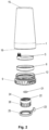
- Fig.1 is an exploded view in cross section of a coffee brewer according to the invention.
- the coffee brewer includes an insulated cup/container 1.
- the container defines an inner volume to be filled with ground coffee, hot/near boiling water up to mark 4 and air.
- the container has a closed end 15 and an open end 16 closed with a lid 9.
- the lid 9 has an inner portion with an inner area and an outside for air tight attachment in the open end.
- the lid 9 has outside / male threads 12 extending into inner/female threads 6 in the container 1. In an alternative embodiment ate these threads substituted with a bayonet coupling, and the threads 6, 12 are then substituted with elements in locking engagement with another.
- Other ways of attaching the lid 9 includes two over the centre locks or one over the centre lock and one hinge (not shown).
- a screw cap coffee diffuser 22 with outlets includes an O-ring seal 21 surrounding a central cylindrical protrusion holding the O-ring 21 in place on an inner surface of the screw cap 22.
- Inner threads 24 in the screw cap 22 are in mating contact with outer threads 27 on a cylindrical protrusion on the lid 9.
- a coffee channel 10 extends through the lid at the cylindrical protrusion on the lid 9.
- the cylindrical protrusion on the lid 9 also includes an annular valve seat 28 or sealing surface for contact with the valve O-ring 21 on the screw cap 22.
- the diameter of the valve O-ring 21 corresponds to the diameter of the annular valve seat 28.
- the outlets on the diffuser are located as cut outs / openings along a diameter inside of the outer periphery on a front portion of the screw cap.
- the inner surface of the end-cap with a central cylindrical protrusion holding the O-ring in place is formed by the inside of the front portion.
- the openings are arc-shaped, and the arcs form a complete surface.
- the arc-shaped outlets and the design of the end-cap diffuser ensures that the pressure inside the coffee brewer not results in a jet of hot coffee out of the brewer.
- the Valve O-ring 21 and the O-ring seat 28 forms a valve, maintaining pressure inside the brewer until the end-cap 22 diffuser is partly unscrewed, unseating the Valve O-ring 21 from the O-ring seat 28, thus allowing coffee to be expelled past the valve O-ring 21, past a cavity formed between a front portion of the cylindrical protrusion of the lid and the inner surface of the end-cap, and out of the arc-shaped openings at the front part of the screw cap 22.
- a handle 23 on a fluted grip ring 25 can be installed around the screw cap 22 to facilitate twisting and opening of the screw cap 22.
- Grooves 26 on the end-cap 22 increases friction when gripping the screw cap 22.
- the grooves 26 also serve to lock the grip ring 25 in place on the screw cap 22.
- the mark 4 inside the container 1 is typically located to divide the volume inside the container to allow 60% water and 40% air inside the container. (leaving 60% of the volume towards the closed end 15, to allow the pouring of boiling water into 60% of the container 1, leaving 40% room for air / steam from the boiling water towards the open end 16).
- the ratio of water to air could be in the range 50 to 60% water, but it is essential that the container not is filled with more that 60% water to enable the air pressure in the container to expel the coffee through the filter.
- a base 37 surround the lid 9, leaving and an end of the end-cap 22 extending beyond the base to ease twisting of the end-cap 22 to open the valve.
- Fig. 2 shows the coffee brewer of fig. 1 from the outside, at a slightly different angle compared to fig. 1 .
- the container 1 with the closed end 15 and the open end 16 in an insulated container to reduce heat loss thorough the container when the coffee is brewing and to prevent burning the hands of an operator when handling the coffee brewer.
- the container 1 should also have a low specific heat capacity to reduce heat loss from the coffee.
- the volume of the container is typically sufficient to brew one or two cups of coffee.
- the heat loss in the coffee should be low to ensure that the air (and some steam) inside the brewer is heated and expands to provide an above atmospheric pressure inside the coffee brewer, and to ensure that the beverage /coffee is hot when it is served.
- the removable locking ring 5 holds a filter (not shown) to the perforated filter holder 8.
- a snap lock, magnets, threads, a bayonet coupling or any other suitable means hold the removable locking ring 5 to the perforated filter holder 8 while holding the filter in place.
- the outer threads 12 holds the lid 9 to the container 1 and closes the open end 16 of the container 1.
- the valve O-ring 21 could be any type of suitable seal not requiring a high surface pressure while keeping its properties at temperatures at around 100°C.
- the inner threads 24 in the end-cap 22 may have a thread pitch adapted to allow the valve O-ring 21 to be sufficiently unseated from the O-ring seat on the lid 9 to allow coffee to be expelled from the coffee brewer upon turning the end-cap approximately a quarter of a turn to be able open the valve and to pour coffee without repositioning the hand.
- Figs. 3 and 4 show details of the lid and screw cap of claim 1.
- Fig. 3 shows the lid with an external fluted gripping surface 34 to facilitate screwing and unscrewing the lid 9 to and from the container.
- the fluted surface is located on an outer surface of the base 37, formed as a cylindrical ring at the periphery of the lid.
- End-cap 22 form the lowermost extremity of the brewer, allowing the valve to be safely opened as the valve is easy to grab beneath the base 37.
- the lid includes an inner surface 38 inside of the filter holder seat 13 allowing coffee to flow towards the channel 10 at the middle the lid at the cylindrical protrusion 31 on the lid.
- Outer threads 27 surrounding the cylindrical protrusion 31 on the lid gripping into inner threads 24 in the screw cap 22 ( fig. 4 ) allows the two parts to be joined.
- a seating surface 28 surrounding the channel 10 seal against the O-ring (shown in fig. 1 ) located in an O-ring seat 33 on the inner surface of the end-cap 22 ( Fig. 4 ) with the central cylindrical protrusion 11 holding the O-ring in place is formed by the inside / inner surface 30 of the front portion 35.
- Fig. 4 shows the outlets 29 located as cut outs / openings in the front portion 35 along a diameter inside of the outer periphery on a front portion 35 of the screw cap 22.
- the outlets 29 are surrounded by a sleeve 36 protruding as a cylindrical ring from the front portion 35 to prevent spillage of coffee onto a hand of an operator when unscrewing the screw cap 22 while holding the coffee brewer in the position for opening the brewer, i.e. in a position with the screw cap 22 facing down as shown in fig. 1 .
- the O-ring seal is located on the lid and the O-ring seat is located on the screw cap.
- the O-ring seat 33 includes a suitable O-ring groove to hold the O-ring in place.
- the Valve O-ring 21 and the O-ring seat 28 forms a valve, maintaining pressure inside the brewer until the end-cap 22 diffuser is partly unscrewed, unseating the Valve O-ring 21 from the O-ring seat 28, thus allowing coffee to be expelled past the Valve O-ring 21, past a cavity formed between a front portion of the cylindrical protrusion of the lid and the inner surface of the end-cap, and out of the arc-shaped openings at the front part of the screw cap 22.
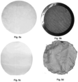
- Figs 5a-5d show various coffee filters that may be used in the coffee brewer of the invention.
- Fig 5a show a disposable paper filter
- fig. 5b show a reusable metal filter
- fig. 5c shows a reusable synthetic mesh filter
- fig. 5d shows a reusable woven cloth/fabric filter.
- Other types of filters such as perforated metal plate filter and various types of synthetic fibre filters may also be used.
- Different filters may be chosen based on preference, how finely the coffee beans are ground etc.
- Freshly brewed coffee is made using the apparatus according to the invention by providing an amount of coffee into the container through the open end of the container (without the lid).
- the amount and type of coffee is decided out of need, desire and experience.
- the amount used can be calculated from the strength that is desired based on the amount of water that is added to the container.
- the container is filled with 60% or less water (of the total inner volume of the container when the lid is installed), for instance 50% of the container volume with hot/boiling water (60-100°C).
- the amount of water that is added is accordingly a proportion below 60 % of the total inner volume of the brewer.
- the water can be heated in advance, and hot water from a vacuum flask may be sufficient.
- the difference between using the brewer of the invention compared to transporting ready made coffee on a vacuum flask is that the brewer of the invention allows consummation of freshly brewed coffee in situ.
- Coffee on a vacuum flask is over time oxidized due to reaction with air and the aroma of the coffee gradually deteriorates.
- the container When the water and ground coffee has been added to the container, the container is closed with the lid with the valve closed. The brewer is now sealed.
- the air and steam above the coffee will then expand and the pressure inside the brewer will increase.
- the increase of pressure is depending on the temperature difference between the ambient temperature and the air inside the brewer.
- the temperature difference between the ambient air and inside the brewer is 80°C. This will result in an increase of pressure. This increase of pressure is used during the brewing / infusion to pull the aroma out of the ground coffee. This may be done by turning the brewer to a position with the lid down when the ground coffee and hot water is poured into the container, the valve is closed and the lid is in place on the container.
- the coffee grounds will accumulate towards the inside of the lid.
- the pressure inside the brewer will press the brewed coffee through the coffee grounds, through the filter, through the valve, through the diffuser and into a cup.
- the pressure is utilized to press the liquid/coffee out of the brewer rather than air out of the valve.
- the filter at the inside of the lid prevent the coffee grounds from being entrained with the coffee when the valve is opened while keeping the valve pointing down.
- the container typically has a volume of 0,4-1,2 litres. Insulated containers of this type are common in connection with thermos cups and thermos flasks. Themocups and flasks of this size are easy to handle and pour from.
- coffee brewer is used as a term to name the invention, because brewing coffee is considered to be the most obvious and important use of the brewer.
- the brewer can however be used to brew other types of beverages brewed from a warm liquid and a substance that has to be filtered away.
- the invention may for instance also be used to brew tea from tea leaves.
- the closed end 15 can include an additional lid, and the claims are not intended to exclude a version with an additional lid at the closed end.
- the method will not need the step of turning the brewer as the brewer in this embodiment is filled with coffee from the closed end with the lid, and the bottom lid is removed for removing coffee grounds.
Landscapes
- Engineering & Computer Science (AREA)
- Food Science & Technology (AREA)
- Apparatus For Making Beverages (AREA)
- Table Devices Or Equipment (AREA)
- Tea And Coffee (AREA)
Claims (7)
- Verfahren zum Aufbrühen von Kaffee mit einer Kaffeeaufbrüheinrichtung nach einem der Ansprüche 2 bis 7, wobei das Verfahren einschließt:Füllen des Behälters (1) bis zu 60 % mit heißem Wasser;Hinzufügen von gemahlenem Kaffee zu dem heißen Wasser;Verschließen des offenen Endes (16) des Behälters mit dem Deckel (9);Drehen der Kaffeeaufbrüheinrichtung, um zu ermöglichen, dass das geschlossene Ende (15) nach oben und der Deckel (9) nach unten weist, um den Behälter (1) über dem Deckel (9) anzuordnen;Halten der Aufbrüheinrichtung über einer Tasse oder einem anderen geeigneten Behälter, während der Deckel (9) nach unten gerichtet gehalten wird; undÖffnen des Ventils, während ermöglicht wird, dass die erhitzte Luft im Inneren der Aufbrüheinrichtung den Kaffee durch den Filter in dem Deckel in die Tasse oder einen anderen geeigneten Behälter presst, ohne dass Kaffee auf einen Bediener verschüttet wird, der das Ventil betätigt.
- Kaffeeaufbrüheinrichtung zum Aufbrühen von Kaffee, die einen Behälter (1) mit einem Innenvolumen, einem geschlossenen Ende (15) und einem offenen Ende (16) einschließt;einen Deckel (9) mit einer Innenseite mit Innenbereich und einer Außenseite zum abdichtenden Anbringen an dem offenen Ende;Auslässe (29) an einem manuell betätigten abgedichteten Ventil in dem Deckel (9), das einen Flussweg zwischen dem Behälter (1) und den Auslässen (29) öffnet oder schließt;einen Kaffeefilter, der an der Innenseite des Deckels (9) in dem Flussweg zwischen dem Behälter (1) und den Auslässen (29) gesichert ist;wobei das Ventil mit einer Endkappe (22) ausgebildet ist, wobei die Auslässe (29) durch eine Griffoberfläche umgeben sind, und einen Ventilsitz einschließt, der einen Kanal (10) in dem Deckel (9) umgibt;die Auslässe (29) angeordnet sind, um ein Ausgießen von Kaffee während des Betätigens des Ventils zu ermöglichen, wodurch das Ventil der Kaffeeaufbrüheinrichtung aus einer geschlossenen Position in eine offene Position betätigt werden kann, wobei das geschlossene Ende (15) nach oben weist und der Behälter (1) über dem Deckel (9) ist;wobei die Auslässe (29) durch eine Hülse (36) umgeben sind, die als zylindrischer Ring von einem vorderen Abschnitt (35) der Endkappe (22) vorsteht, wodurch ein Verschütten von Kaffee auf die Hand eines Bedieners beim Abschrauben der Endkappe (22) verhindert wird;wobei die Auslässe (29) an dem vorderen Abschnitt (35) der Endkappe (22) als eine Vielzahl von individuellen Auslässen verteilt sind, wodurch die Endkappe (22) den Kaffeefluss dämpft, um Kaffeeausstoßungen aus der Endkappe (22) zu verhindern;wobei die Auslässe (29) an dem vorderen Abschnitt (35) der Endkappe (22) einzelne bogenförmige Öffnungen ausbilden und die Bögen einen vollständigen Kreis ausbilden, der eine Vorderfläche der Endkappe (22) umgibt; undwobei die Endkappe (22) einen zentral angeordneten zylindrischen Abschnitt, der einen O-Ring hält, und einen zylindrischen Abschnitt mit Innengewinde (24) einschließt.
- Kaffeeaufbrüheinrichtung nach Anspruch 2, wobei der Behälter (1) isoliert ist.
- Kaffeeaufbrüheinrichtung nach einem der Ansprüche 2 oder 3, die ferner einen Spalt zwischen der inneren Deckeloberfläche und einem kreisförmigen, perforierten Filterhalter (8) einschließt, der einen Hohlraum ausbildet, und wobei sich der Flussweg durch diesen Hohlraum und einen Kaffeekanal (10) in dem Deckel (9) erstreckt.
- Kaffeeaufbrüheinrichtung nach einem der Ansprüche 2 bis 4, wobei der Deckel eine Innenoberfläche (38) im Inneren des Filterhaltersitzes (13) einschließt, die es ermöglicht, dass Kaffee zu dem Kanal (10) hin in der Mitte des Deckels an einem zylindrischen Vorsprung (31) auf dem Deckel fließt.
- Kaffeeaufbrüheinrichtung nach Anspruch 5, sofern dieser von Anspruch 4 abhängig ist, wobei der Filtersitz den Filterhalter (8) an dem Deckel (9) entlang eines Umfangs des Filterhalters (8) sichert und abdichtet.
- Kaffeeaufbrüheinrichtung nach einem der Ansprüche 2 bis 6, wobei der Filter als eine flache, kreisförmige Scheibe geformt ist.
Applications Claiming Priority (2)
| Application Number | Priority Date | Filing Date | Title |
|---|---|---|---|
| NO20161995A NO343161B1 (no) | 2016-12-15 | 2016-12-15 | Kaffebrygger |
| PCT/NO2017/050330 WO2018111119A1 (en) | 2016-12-15 | 2017-12-15 | Coffee brewer |
Publications (3)
| Publication Number | Publication Date |
|---|---|
| EP3554318A1 EP3554318A1 (de) | 2019-10-23 |
| EP3554318A4 EP3554318A4 (de) | 2020-06-24 |
| EP3554318B1 true EP3554318B1 (de) | 2025-06-04 |
Family
ID=62559068
Family Applications (1)
| Application Number | Title | Priority Date | Filing Date |
|---|---|---|---|
| EP17880782.2A Active EP3554318B1 (de) | 2016-12-15 | 2017-12-15 | Kaffeebrühvorrichtung |
Country Status (9)
| Country | Link |
|---|---|
| US (1) | US11470992B2 (de) |
| EP (1) | EP3554318B1 (de) |
| JP (1) | JP7141128B2 (de) |
| KR (1) | KR102446616B1 (de) |
| CN (1) | CN110121283B (de) |
| BR (1) | BR112019012444A2 (de) |
| NO (1) | NO343161B1 (de) |
| RU (1) | RU2759376C2 (de) |
| WO (1) | WO2018111119A1 (de) |
Families Citing this family (8)
| Publication number | Priority date | Publication date | Assignee | Title |
|---|---|---|---|---|
| BE1028065B1 (nl) * | 2020-02-18 | 2021-09-15 | Koffie F Rombouts | Filter voor de bereiding van koffie of infuus |
| CH717836A9 (de) * | 2020-09-10 | 2022-04-29 | Swiss Tea Innovation Ag | Auslassventil für einen Aufgussbehälter und Aufgussbehälter. |
| US20230002128A1 (en) * | 2021-07-02 | 2023-01-05 | Jeff L. Jorden | Threaded Tumbler Bottle Cap |
| CN113917956A (zh) * | 2021-10-29 | 2022-01-11 | 大连富士冰山自动售货机有限公司 | 一种可提高自助咖啡机连续售卖性的温度控制方法 |
| US12565360B2 (en) | 2023-02-09 | 2026-03-03 | Yeti Coolers, Llc | Container and method of forming a container |
| USD1093980S1 (en) | 2023-11-13 | 2025-09-23 | Yeti Coolers, Llc | Beverage maker |
| USD1093081S1 (en) | 2023-11-13 | 2025-09-16 | Yeti Coolers, Llc | Beverage maker |
| USD1092136S1 (en) | 2023-11-13 | 2025-09-09 | Yeti Coolers, Llc | Lid for a beverage maker |
Citations (1)
| Publication number | Priority date | Publication date | Assignee | Title |
|---|---|---|---|---|
| EP1260165A1 (de) * | 2001-05-14 | 2002-11-27 | Eva Denmark A/S | Kaffeekanne |
Family Cites Families (18)
| Publication number | Priority date | Publication date | Assignee | Title |
|---|---|---|---|---|
| US2686597A (en) * | 1951-05-03 | 1954-08-17 | Club Aluminum Products Company | Liquid straining closure for containers |
| JPS58109433U (ja) * | 1982-07-17 | 1983-07-26 | タイガー魔法瓶株式会社 | 魔法瓶などの液体容器の栓 |
| BR6201078U (pt) * | 1982-08-10 | 1984-03-20 | Termolar Sa | Recipiente isotermico com tampa copo |
| JP3052231U (ja) * | 1998-03-12 | 1998-09-14 | 良夫 萬木 | ドリップ速度の調節可能なコーヒードリッパー |
| US6164495A (en) * | 1999-11-02 | 2000-12-26 | Manesis; Nick J. | Metered dispensing device |
| IT1318965B1 (it) * | 2000-10-04 | 2003-09-19 | Adriana Brizio | Caffettiera. |
| US7032507B2 (en) * | 2001-09-01 | 2006-04-25 | Cai Edward Z | Device and method for brewing coffee and espresso beverages |
| US6494128B1 (en) * | 2002-05-08 | 2002-12-17 | Hong Chao Yu | Infusing container |
| US6945393B2 (en) * | 2002-12-24 | 2005-09-20 | Young Kook Cho | Cap device for attachment to a container |
| CN201076362Y (zh) * | 2007-07-06 | 2008-06-25 | 元扬企业有限公司 | 具有流量控制装置的冲泡机过滤器与流量控制装置 |
| US8230777B2 (en) * | 2008-07-21 | 2012-07-31 | Nutra-Life, Inc. | Water container cap for holding additives to water |
| US9717365B2 (en) | 2011-06-13 | 2017-08-01 | National Presto Industries, Inc. | Pump coffee brewer |
| US8459468B2 (en) * | 2011-07-11 | 2013-06-11 | Shin-Shuoh Lin | Vacuum mug separable cap |
| US9516974B2 (en) * | 2012-03-09 | 2016-12-13 | Precidio Design Inc. | Container for liquids and set for making the same |
| CN203195449U (zh) * | 2013-04-09 | 2013-09-18 | 肖保土 | 一种冲饮机增压过滤器 |
| US9801492B1 (en) * | 2014-02-18 | 2017-10-31 | Shin-Shuoh Lin | Liquid container with interchangeable attachments |
| WO2016014570A1 (en) | 2014-07-21 | 2016-01-28 | Abbott Laboratories | Pod for use with a beverage dispensing device and including a movable outlet member |
| CN205338653U (zh) * | 2015-11-23 | 2016-06-29 | 小田(中山)实业有限公司 | 手冲杯咖啡漏斗 |
-
2016
- 2016-12-15 NO NO20161995A patent/NO343161B1/no unknown
-
2017
- 2017-12-15 CN CN201780078173.7A patent/CN110121283B/zh active Active
- 2017-12-15 EP EP17880782.2A patent/EP3554318B1/de active Active
- 2017-12-15 RU RU2019121856A patent/RU2759376C2/ru active
- 2017-12-15 US US16/469,996 patent/US11470992B2/en active Active
- 2017-12-15 KR KR1020197020177A patent/KR102446616B1/ko active Active
- 2017-12-15 BR BR112019012444A patent/BR112019012444A2/pt not_active IP Right Cessation
- 2017-12-15 JP JP2019554469A patent/JP7141128B2/ja active Active
- 2017-12-15 WO PCT/NO2017/050330 patent/WO2018111119A1/en not_active Ceased
Patent Citations (1)
| Publication number | Priority date | Publication date | Assignee | Title |
|---|---|---|---|---|
| EP1260165A1 (de) * | 2001-05-14 | 2002-11-27 | Eva Denmark A/S | Kaffeekanne |
Also Published As
| Publication number | Publication date |
|---|---|
| US20200085226A1 (en) | 2020-03-19 |
| WO2018111119A1 (en) | 2018-06-21 |
| RU2759376C2 (ru) | 2021-11-12 |
| BR112019012444A2 (pt) | 2020-04-14 |
| KR20190096372A (ko) | 2019-08-19 |
| RU2019121856A3 (de) | 2021-02-24 |
| RU2019121856A (ru) | 2021-01-15 |
| NO343161B1 (no) | 2018-11-19 |
| CN110121283B (zh) | 2022-07-05 |
| KR102446616B1 (ko) | 2022-09-22 |
| EP3554318A4 (de) | 2020-06-24 |
| EP3554318A1 (de) | 2019-10-23 |
| NO20161995A1 (no) | 2018-06-18 |
| CN110121283A (zh) | 2019-08-13 |
| JP7141128B2 (ja) | 2022-09-22 |
| US11470992B2 (en) | 2022-10-18 |
| JP2020501869A (ja) | 2020-01-23 |
Similar Documents
| Publication | Publication Date | Title |
|---|---|---|
| EP3554318B1 (de) | Kaffeebrühvorrichtung | |
| US9179798B2 (en) | Method and apparatus for brewing coffee and the like | |
| US20110146496A1 (en) | Beverage preparation device comprising an insert inserted into a receptacle | |
| US4565121A (en) | Apparatus for use in preparing infusions | |
| US6026733A (en) | Device for making coffee and espresso beverages in microwave oven | |
| US20100263548A1 (en) | Drink extracting apparatus | |
| US9526368B2 (en) | Single cup coffee and tea brewing system | |
| US9648976B2 (en) | Commuter java press | |
| US20170280913A1 (en) | Knockdown pour-over kettle and kettle cover thereof | |
| RU2761273C2 (ru) | Устройство и способы на основе настаивания для заваривания напитка | |
| US20150327713A1 (en) | Single serve brewing system for drip coffee makers | |
| US20100040749A1 (en) | Method of brewing beverage in an electric, drip-type beverage brewer | |
| US20110303094A1 (en) | Coffee maker | |
| US9861225B1 (en) | Single cup coffee and tea manual brewing system | |
| WO2016161024A1 (en) | Apparatus and method for brewing beverages | |
| WO2011101769A2 (en) | Coffee-maker with a frothing device | |
| US20140182458A1 (en) | Microwave Beverage Cartridge Holder | |
| US2467817A (en) | Coffee-making device | |
| US20200305632A1 (en) | Beverage Brewing Apparatus | |
| CN105744866B (zh) | 配备有蒸汽回收装置的浸泡饮料的生产设备 | |
| WO2015174967A1 (en) | Single serve brewing system for drip coffee makers | |
| WO2010075434A1 (en) | Self-heating mug | |
| TWM551463U (zh) | 過濾壺的過濾結構 | |
| HK1171635A1 (en) | Tea-maker having a closable pouring spout | |
| HK1171635B (en) | Tea-maker having a closable pouring spout |
Legal Events
| Date | Code | Title | Description |
|---|---|---|---|
| STAA | Information on the status of an ep patent application or granted ep patent |
Free format text: STATUS: THE INTERNATIONAL PUBLICATION HAS BEEN MADE |
|
| PUAI | Public reference made under article 153(3) epc to a published international application that has entered the european phase |
Free format text: ORIGINAL CODE: 0009012 |
|
| STAA | Information on the status of an ep patent application or granted ep patent |
Free format text: STATUS: REQUEST FOR EXAMINATION WAS MADE |
|
| 17P | Request for examination filed |
Effective date: 20190612 |
|
| AK | Designated contracting states |
Kind code of ref document: A1 Designated state(s): AL AT BE BG CH CY CZ DE DK EE ES FI FR GB GR HR HU IE IS IT LI LT LU LV MC MK MT NL NO PL PT RO RS SE SI SK SM TR |
|
| AX | Request for extension of the european patent |
Extension state: BA ME |
|
| DAV | Request for validation of the european patent (deleted) | ||
| DAX | Request for extension of the european patent (deleted) | ||
| A4 | Supplementary search report drawn up and despatched |
Effective date: 20200527 |
|
| RIC1 | Information provided on ipc code assigned before grant |
Ipc: A47J 31/06 20060101ALI20200519BHEP Ipc: A47J 31/14 20060101AFI20200519BHEP Ipc: A47J 31/18 20060101ALI20200519BHEP |
|
| STAA | Information on the status of an ep patent application or granted ep patent |
Free format text: STATUS: EXAMINATION IS IN PROGRESS |
|
| 17Q | First examination report despatched |
Effective date: 20201030 |
|
| GRAP | Despatch of communication of intention to grant a patent |
Free format text: ORIGINAL CODE: EPIDOSNIGR1 |
|
| STAA | Information on the status of an ep patent application or granted ep patent |
Free format text: STATUS: GRANT OF PATENT IS INTENDED |
|
| INTG | Intention to grant announced |
Effective date: 20250114 |
|
| GRAS | Grant fee paid |
Free format text: ORIGINAL CODE: EPIDOSNIGR3 |
|
| GRAA | (expected) grant |
Free format text: ORIGINAL CODE: 0009210 |
|
| STAA | Information on the status of an ep patent application or granted ep patent |
Free format text: STATUS: THE PATENT HAS BEEN GRANTED |
|
| AK | Designated contracting states |
Kind code of ref document: B1 Designated state(s): AL AT BE BG CH CY CZ DE DK EE ES FI FR GB GR HR HU IE IS IT LI LT LU LV MC MK MT NL NO PL PT RO RS SE SI SK SM TR |
|
| REG | Reference to a national code |
Ref country code: GB Ref legal event code: FG4D |
|
| REG | Reference to a national code |
Ref country code: CH Ref legal event code: EP |
|
| REG | Reference to a national code |
Ref country code: DE Ref legal event code: R096 Ref document number: 602017089824 Country of ref document: DE |
|
| REG | Reference to a national code |
Ref country code: IE Ref legal event code: FG4D |
|
| REG | Reference to a national code |
Ref country code: NL Ref legal event code: MP Effective date: 20250604 |
|
| PG25 | Lapsed in a contracting state [announced via postgrant information from national office to epo] |
Ref country code: FI Free format text: LAPSE BECAUSE OF FAILURE TO SUBMIT A TRANSLATION OF THE DESCRIPTION OR TO PAY THE FEE WITHIN THE PRESCRIBED TIME-LIMIT Effective date: 20250604 Ref country code: ES Free format text: LAPSE BECAUSE OF FAILURE TO SUBMIT A TRANSLATION OF THE DESCRIPTION OR TO PAY THE FEE WITHIN THE PRESCRIBED TIME-LIMIT Effective date: 20250604 |
|
| REG | Reference to a national code |
Ref country code: LT Ref legal event code: MG9D |
|
| PG25 | Lapsed in a contracting state [announced via postgrant information from national office to epo] |
Ref country code: GR Free format text: LAPSE BECAUSE OF FAILURE TO SUBMIT A TRANSLATION OF THE DESCRIPTION OR TO PAY THE FEE WITHIN THE PRESCRIBED TIME-LIMIT Effective date: 20250905 Ref country code: NO Free format text: LAPSE BECAUSE OF FAILURE TO SUBMIT A TRANSLATION OF THE DESCRIPTION OR TO PAY THE FEE WITHIN THE PRESCRIBED TIME-LIMIT Effective date: 20250904 |
|
| PG25 | Lapsed in a contracting state [announced via postgrant information from national office to epo] |
Ref country code: PL Free format text: LAPSE BECAUSE OF FAILURE TO SUBMIT A TRANSLATION OF THE DESCRIPTION OR TO PAY THE FEE WITHIN THE PRESCRIBED TIME-LIMIT Effective date: 20250604 |
|
| PG25 | Lapsed in a contracting state [announced via postgrant information from national office to epo] |
Ref country code: BG Free format text: LAPSE BECAUSE OF FAILURE TO SUBMIT A TRANSLATION OF THE DESCRIPTION OR TO PAY THE FEE WITHIN THE PRESCRIBED TIME-LIMIT Effective date: 20250604 |
|
| PG25 | Lapsed in a contracting state [announced via postgrant information from national office to epo] |
Ref country code: HR Free format text: LAPSE BECAUSE OF FAILURE TO SUBMIT A TRANSLATION OF THE DESCRIPTION OR TO PAY THE FEE WITHIN THE PRESCRIBED TIME-LIMIT Effective date: 20250604 |
|
| PG25 | Lapsed in a contracting state [announced via postgrant information from national office to epo] |
Ref country code: RS Free format text: LAPSE BECAUSE OF FAILURE TO SUBMIT A TRANSLATION OF THE DESCRIPTION OR TO PAY THE FEE WITHIN THE PRESCRIBED TIME-LIMIT Effective date: 20250904 |
|
| PG25 | Lapsed in a contracting state [announced via postgrant information from national office to epo] |
Ref country code: LV Free format text: LAPSE BECAUSE OF FAILURE TO SUBMIT A TRANSLATION OF THE DESCRIPTION OR TO PAY THE FEE WITHIN THE PRESCRIBED TIME-LIMIT Effective date: 20250604 |
|
| PG25 | Lapsed in a contracting state [announced via postgrant information from national office to epo] |
Ref country code: NL Free format text: LAPSE BECAUSE OF FAILURE TO SUBMIT A TRANSLATION OF THE DESCRIPTION OR TO PAY THE FEE WITHIN THE PRESCRIBED TIME-LIMIT Effective date: 20250604 |
|
| PG25 | Lapsed in a contracting state [announced via postgrant information from national office to epo] |
Ref country code: PT Free format text: LAPSE BECAUSE OF FAILURE TO SUBMIT A TRANSLATION OF THE DESCRIPTION OR TO PAY THE FEE WITHIN THE PRESCRIBED TIME-LIMIT Effective date: 20251006 |
|
| REG | Reference to a national code |
Ref country code: AT Ref legal event code: MK05 Ref document number: 1799492 Country of ref document: AT Kind code of ref document: T Effective date: 20250604 |
|
| PG25 | Lapsed in a contracting state [announced via postgrant information from national office to epo] |
Ref country code: IS Free format text: LAPSE BECAUSE OF FAILURE TO SUBMIT A TRANSLATION OF THE DESCRIPTION OR TO PAY THE FEE WITHIN THE PRESCRIBED TIME-LIMIT Effective date: 20251004 |
|
| PG25 | Lapsed in a contracting state [announced via postgrant information from national office to epo] |
Ref country code: SM Free format text: LAPSE BECAUSE OF FAILURE TO SUBMIT A TRANSLATION OF THE DESCRIPTION OR TO PAY THE FEE WITHIN THE PRESCRIBED TIME-LIMIT Effective date: 20250604 Ref country code: AT Free format text: LAPSE BECAUSE OF FAILURE TO SUBMIT A TRANSLATION OF THE DESCRIPTION OR TO PAY THE FEE WITHIN THE PRESCRIBED TIME-LIMIT Effective date: 20250604 |
|
| PG25 | Lapsed in a contracting state [announced via postgrant information from national office to epo] |
Ref country code: CZ Free format text: LAPSE BECAUSE OF FAILURE TO SUBMIT A TRANSLATION OF THE DESCRIPTION OR TO PAY THE FEE WITHIN THE PRESCRIBED TIME-LIMIT Effective date: 20250604 |
|
| PG25 | Lapsed in a contracting state [announced via postgrant information from national office to epo] |
Ref country code: EE Free format text: LAPSE BECAUSE OF FAILURE TO SUBMIT A TRANSLATION OF THE DESCRIPTION OR TO PAY THE FEE WITHIN THE PRESCRIBED TIME-LIMIT Effective date: 20250604 |
|
| PG25 | Lapsed in a contracting state [announced via postgrant information from national office to epo] |
Ref country code: RO Free format text: LAPSE BECAUSE OF FAILURE TO SUBMIT A TRANSLATION OF THE DESCRIPTION OR TO PAY THE FEE WITHIN THE PRESCRIBED TIME-LIMIT Effective date: 20250604 Ref country code: SK Free format text: LAPSE BECAUSE OF FAILURE TO SUBMIT A TRANSLATION OF THE DESCRIPTION OR TO PAY THE FEE WITHIN THE PRESCRIBED TIME-LIMIT Effective date: 20250604 |
|
| PG25 | Lapsed in a contracting state [announced via postgrant information from national office to epo] |
Ref country code: IT Free format text: LAPSE BECAUSE OF FAILURE TO SUBMIT A TRANSLATION OF THE DESCRIPTION OR TO PAY THE FEE WITHIN THE PRESCRIBED TIME-LIMIT Effective date: 20250604 |