EP3554090A1 - Synchronisationssteuerungsvorrichtung und synchronisationssteuerungsverfahren - Google Patents
Synchronisationssteuerungsvorrichtung und synchronisationssteuerungsverfahren Download PDFInfo
- Publication number
- EP3554090A1 EP3554090A1 EP19168815.9A EP19168815A EP3554090A1 EP 3554090 A1 EP3554090 A1 EP 3554090A1 EP 19168815 A EP19168815 A EP 19168815A EP 3554090 A1 EP3554090 A1 EP 3554090A1
- Authority
- EP
- European Patent Office
- Prior art keywords
- time
- synchronization control
- tai
- stc counter
- remainder
- Prior art date
- Legal status (The legal status is an assumption and is not a legal conclusion. Google has not performed a legal analysis and makes no representation as to the accuracy of the status listed.)
- Granted
Links
Images


Classifications
-
- H—ELECTRICITY
- H04—ELECTRIC COMMUNICATION TECHNIQUE
- H04L—TRANSMISSION OF DIGITAL INFORMATION, e.g. TELEGRAPHIC COMMUNICATION
- H04L7/00—Arrangements for synchronising receiver with transmitter
- H04L7/0054—Detection of the synchronisation error by features other than the received signal transition
-
- G—PHYSICS
- G06—COMPUTING OR CALCULATING; COUNTING
- G06F—ELECTRIC DIGITAL DATA PROCESSING
- G06F1/00—Details not covered by groups G06F3/00 - G06F13/00 and G06F21/00
- G06F1/04—Generating or distributing clock signals or signals derived directly therefrom
- G06F1/08—Clock generators with changeable or programmable clock frequency
-
- G—PHYSICS
- G06—COMPUTING OR CALCULATING; COUNTING
- G06F—ELECTRIC DIGITAL DATA PROCESSING
- G06F1/00—Details not covered by groups G06F3/00 - G06F13/00 and G06F21/00
- G06F1/04—Generating or distributing clock signals or signals derived directly therefrom
- G06F1/12—Synchronisation of different clock signals provided by a plurality of clock generators
-
- H—ELECTRICITY
- H04—ELECTRIC COMMUNICATION TECHNIQUE
- H04H—BROADCAST COMMUNICATION
- H04H20/00—Arrangements for broadcast or for distribution combined with broadcast
- H04H20/18—Arrangements for synchronising broadcast or distribution via plural systems
-
- H—ELECTRICITY
- H04—ELECTRIC COMMUNICATION TECHNIQUE
- H04H—BROADCAST COMMUNICATION
- H04H60/00—Arrangements for broadcast applications with a direct linking to broadcast information or broadcast space-time; Broadcast-related systems
- H04H60/35—Arrangements for identifying or recognising characteristics with a direct linkage to broadcast information or to broadcast space-time, e.g. for identifying broadcast stations or for identifying users
- H04H60/38—Arrangements for identifying or recognising characteristics with a direct linkage to broadcast information or to broadcast space-time, e.g. for identifying broadcast stations or for identifying users for identifying broadcast time or space
- H04H60/40—Arrangements for identifying or recognising characteristics with a direct linkage to broadcast information or to broadcast space-time, e.g. for identifying broadcast stations or for identifying users for identifying broadcast time or space for identifying broadcast time
-
- H—ELECTRICITY
- H04—ELECTRIC COMMUNICATION TECHNIQUE
- H04J—MULTIPLEX COMMUNICATION
- H04J3/00—Time-division multiplex systems
- H04J3/02—Details
- H04J3/06—Synchronising arrangements
- H04J3/0635—Clock or time synchronisation in a network
- H04J3/0638—Clock or time synchronisation among nodes; Internode synchronisation
- H04J3/0658—Clock or time synchronisation among packet nodes
- H04J3/0661—Clock or time synchronisation among packet nodes using timestamps
- H04J3/0667—Bidirectional timestamps, e.g. NTP or PTP for compensation of clock drift and for compensation of propagation delays
-
- H—ELECTRICITY
- H04—ELECTRIC COMMUNICATION TECHNIQUE
- H04N—PICTORIAL COMMUNICATION, e.g. TELEVISION
- H04N21/00—Selective content distribution, e.g. interactive television or video on demand [VOD]
- H04N21/20—Servers specifically adapted for the distribution of content, e.g. VOD servers; Operations thereof
- H04N21/23—Processing of content or additional data; Elementary server operations; Server middleware
- H04N21/236—Assembling of a multiplex stream, e.g. transport stream, by combining a video stream with other content or additional data, e.g. inserting a URL [Uniform Resource Locator] into a video stream, multiplexing software data into a video stream; Remultiplexing of multiplex streams; Insertion of stuffing bits into the multiplex stream, e.g. to obtain a constant bit-rate; Assembling of a packetised elementary stream
-
- H—ELECTRICITY
- H04—ELECTRIC COMMUNICATION TECHNIQUE
- H04N—PICTORIAL COMMUNICATION, e.g. TELEVISION
- H04N21/00—Selective content distribution, e.g. interactive television or video on demand [VOD]
- H04N21/20—Servers specifically adapted for the distribution of content, e.g. VOD servers; Operations thereof
- H04N21/23—Processing of content or additional data; Elementary server operations; Server middleware
- H04N21/242—Synchronisation processes, e.g. processing of PCR [Programme Clock References]
-
- H—ELECTRICITY
- H04—ELECTRIC COMMUNICATION TECHNIQUE
- H04N—PICTORIAL COMMUNICATION, e.g. TELEVISION
- H04N21/00—Selective content distribution, e.g. interactive television or video on demand [VOD]
- H04N21/40—Client devices specifically adapted for the reception of or interaction with content, e.g. set-top-box [STB]; Operations thereof
- H04N21/43—Processing of content or additional data, e.g. demultiplexing additional data from a digital video stream; Elementary client operations, e.g. monitoring of home network or synchronising decoder's clock; Client middleware
- H04N21/4302—Content synchronisation processes, e.g. decoder synchronisation
- H04N21/4305—Synchronising client clock from received content stream, e.g. locking decoder clock with encoder clock, extraction of the PCR packets
-
- H—ELECTRICITY
- H04—ELECTRIC COMMUNICATION TECHNIQUE
- H04N—PICTORIAL COMMUNICATION, e.g. TELEVISION
- H04N21/00—Selective content distribution, e.g. interactive television or video on demand [VOD]
- H04N21/80—Generation or processing of content or additional data by content creator independently of the distribution process; Content per se
- H04N21/85—Assembly of content; Generation of multimedia applications
- H04N21/854—Content authoring
- H04N21/8547—Content authoring involving timestamps for synchronizing content
Definitions
- Embodiments of the present invention relate to an apparatus and method for inter-system synchronization control in a broadcasting system or a distribution system, such as a terrestrial digital broadcasting system, a satellite broadcasting system or an IP retransmission system.
- a broadcasting system or a distribution system such as a terrestrial digital broadcasting system, a satellite broadcasting system or an IP retransmission system.
- a redundant system is constructed on the assumption of an apparatus fault or apparatus maintenance.
- STC counter values are first sampled, and are input as PCR (Program Clock Reference) to each apparatus (e.g. MPEG encoder, TS multiplexing apparatus) in PCR packet format. Thereby, the STC counter values in the respective apparatuses are synchronized.
- PCR Program Clock Reference
- the PCR packet signal is distributed to each apparatus by a DVB-ASI interface (coaxial cable). Aside from this, video/audio/auxiliary signals are transmitted between apparatuses by an SDI interface (coaxial cable).
- the object of the present invention is to provide a synchronization control apparatus and synchronization control method which can synchronize STC counter values, thereby to realize seamless switching between systems in a broadcast system or distribution system in which interfaces are constructed by IP-based implementation.
- a synchronization control apparatus of an embodiment synchronizes an STC counter value, based on TAI (Temps Atomique International: international atomic time) time, in each of systems which constitute a transmission system in a broadcasting system or a distribution system.
- the synchronization control apparatus includes a processor or a dedicated arithmetic circuit.
- the processor or the dedicated arithmetic circuit is configured to determine a time length in which the STC counter value laps, to calculate a remainder of the time length relative to the TAI time, and to convert the remainder to the STC counter value, thereby determining the STC counter value.
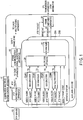
- FIG. 1 is a configuration view illustrating an example of a compression multiplex system control apparatus to which the synchronization control method and synchronization control apparatus of the first embodiment are applied.
- a compression multiplex system control apparatus 10 illustrated in FIG. 1 is an apparatus provided in a broadcasting system or distribution system, such as a terrestrial digital broadcasting system, a satellite broadcasting system or an IP retransmission system.
- the compression multiplex system control apparatus 10 compression-encodes video/audio and PTP packets, generates broadcast TS signals according to a terrestrial digital broadcast method, and outputs the broadcast TS signals to transmission equipment.
- the compression multiplex system control apparatus 10 includes a working system 20A and an auxiliary system 20B, which have the same configuration, for the purpose of redundancy.
- Each of the working system 20A and auxiliary system 20B includes a plurality of encoders 22(#1) to 22(#4), a multiplexing apparatus 24, and a scrambler 25.
- the synchronization control apparatus of the present embodiment is assembled in the encoders 22(#1) to 22(#4) and multiplexing apparatuses 24 in both systems 20A and 20B, and the synchronization control method of the embodiment is implemented in the encoders 22(#1) to 22(#4) and multiplexing apparatuses 24 in both systems 20A and 20B.
- the details of the synchronization control implemented in the encoders 22(#1) to 22(#4) and multiplexing apparatuses 24 will be described in the detailed description of the encoder 24 and multiplexing apparatus 24, which will be given later.
- the compression multiplex system control apparatus 10 includes a frame switching apparatus 30 which is provided common to the working system 20A and auxiliary system 20B.
- the compression multiplex system control apparatus 10 further includes a PTP distribution apparatus 40 which distributes PTP packets, which are delivered from a PTP server 60 provided outside the compression multiplex system control apparatus 10, to the encoders 22(#1) to 22(#4), multiplexing apparatuses 24 and frame switching apparatus 30.
- PTP distribution apparatus 40 which distributes PTP packets, which are delivered from a PTP server 60 provided outside the compression multiplex system control apparatus 10, to the encoders 22(#1) to 22(#4), multiplexing apparatuses 24 and frame switching apparatus 30.
- the compression multiplex system control apparatus 10 includes a frame synchronization signal generation apparatus 50 which generates ISDB-T (Integrated Services Digital Broadcasting-Terrestrial) frame synchronization signals, and outputs the generated ISDB-T frame synchronization signals to each multiplexing apparatus 24.
- ISDB-T Integrated Services Digital Broadcasting-Terrestrial
- the frame synchronization signal generation apparatus 50 is also applicable to other broadcasting methods using TS, such as ISDB-S, ATSC (Advanced Television Systems Committee standard) and DVB (Digital Video Broadcasting) methods.
- Each of the encoder 22(#1) (HD encoder), encoder 22(#2) (SD1 encoder), encoder 22(#3) (SD2 encoder) and encoder 22(#4) (One-Seg encoder that uses only one segment of the bandwidth in the ISDB-T broadcast system) compression-encodes video/audio by using PTP packets distributed from the PTP distribution apparatus 40, and outputs the compression-encoded video/audio to the multiplexing apparatus 24.
- the video signals and PTP packets may be input to each of the encoders 22(#1) to 22(#4) by one Ethernet cable.
- the video signals and PTP packets may be input to all encoders 22(#1) to 22(#4) by one common Ethernet cable.
- FIG. 1 illustrates four encoders 22, the number of encoders 22 is not limited to four, and may be three or less, or five or more.
- the multiplexing apparatus 24 multiplexes the video/audio, which is compression-encoded by each of the encoders 22(#1) to 22(#4), into a broadcast TS signal having an ISDB-T frame structure, by using the PTP packets output from the PTP distribution apparatus 40 and the ISDB-T frames output from the frame synchronization signal generation apparatus 50, and outputs the broadcast TS signal to the scrambler 25.
- the scrambler 25 executes a scramble process on the broadcast TS signal output from the multiplexing apparatus 24, and outputs the scramble-processed broadcast TS signal to the frame switching apparatus 30.
- the frame switching apparatus 30 performs frame phase adjustment on the broadcast TS signal output from the scrambler 25, by using the PTP packets distributed from the PTP distribution apparatus 40, and outputs the frame-phase-adjusted broadcast TS signal to transmission equipment such as an STL transmission apparatus, OFDM modulator, or the like.
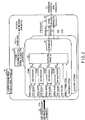
- FIG. 2 is a configuration view illustrating another example of the compression multiplex system control apparatus to which the synchronization control method and synchronization control apparatus of the first embodiment are applied.
- a compression multiplex system control apparatus 10' illustrated in FIG. 2 is a modification of the compression multiplex system control apparatus 10 illustrated in FIG. 1 .
- the compression multiplex system control apparatus 10' does not include the PTP distribution apparatus 40, and includes, instead, a PTP server/distribution apparatus 70, in which the PTP server 60 and distribution apparatus 40 illustrated in FIG. 1 are integrated, on the outside of the compression multiplex system control apparatus 10'.
- the PTP server/distribution apparatus 70 outputs PTP packets to the encoders 22(#1) to 22(#4), multiplexing apparatuses 24 and frame switching apparatus 30.
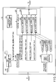
- FIG. 3 is a conceptual view illustrating a configuration example of the encoder 22 to which the synchronization control method and synchronization control apparatus of the first embodiment are applied.
- the encoder 22 includes a processor (not shown) and a program memory (not shown).
- the encoder 22 includes, as necessary control functions for implementing the present embodiment, a time reproduction unit 22a, a TAI/STC converter 22b, a TS packet generation timing controller 22c, a video/audio/subtitle separator 22d (hereinafter, simply referred to as "separator 22d"), a video encoder 22e1, an audio encoder 22e2, and a TS packet generator 22f.
- These control functions are realized by causing the CPU to execute programs stored in the program memory.
- the TS packet generator 22f further includes a PCR packet generator 22f1, a video packet generator 22f2, an audio packet generator 22f3, a subtitle packet generator 22f4, and a selector 22f5.
- video/audio and PTP packets are input to the encoder 22.
- the video/audio and PTP packets are input in the form of IP packets.
- video/audio is a MoIP packet.
- the time reproduction unit 22a receives the PTP packet included in the input IP packet, samples TAI time at the time of receiving the PTP packet, and outputs the sampled TAI time to the TAI/STC converter 22b.
- the TAI time is a time based on January 1, 1970 as the reference time.
- the TAI/STC converter 22b converts the TAI time, which is output from the time reproduction unit 22a, to STC counter values (PCR value, PTS value, DTS value). These STC counter values are used for synchronization control between the systems.
- the TAI/STC converter 22b operates as a synchronization control apparatus by which the synchronization control method of the present embodiment is implemented in the corresponding encoders 22 of the working system 20A and auxiliary system 20B.
- the TAI time is expressed, for example, by 80 bits in total, which include 48 bits of an integer second and 32 bits of a decimal second.
- a 64-bit CPU which is now widely used, cannot simply perform arithmetic operations which treat 80 bits.
- a decimal fraction (e.g. recurring decimal), which cannot exactly be expressed by a power of 2, is treated.
- an error occurs between difference apparatuses when the TAI time is converted to STC counter values.
- a predetermined rule e.g. round-off to millisecond precision
- the present embodiment shows a method of converting the TAI time to STC counter values with higher precision.
- the TAI/STC converter 22b of each encoder, 22(#1) to 22(#4) repeats a process of narrowing the range of values which are treated in the range in which calculation by 64-bit operations is possible, so that an error occurs only in the last step.
- a time length (e.g. 2 33 /90,000 seconds), in which the STC counter value laps, is determined, and a remainder of the time length (e.g. 2 33 /90,000 seconds) relative to the TAI time is calculated.
- a remainder of an integer or a finite decimal which is obtained by multiplying the time length (e.g. 2 33 /90,000 seconds), in which the STC counter value laps, by an integer, is calculated.
- the remainder is calculated by the finite decimal
- the TAI time and the finite decimal are multiplied by 10 n (n is a natural number), so that the finite decimal becomes an integer.
- the calculated remainder is converted to the STC counter value (e.g. a PCR value composed of a base of 90 kHz and an extension of 27 kHz).
- the STC counter value is determined as a PCR value composed of a base of a first frequency and an extension of a second frequency.
- an integer second is 48 bits (binary number), and a decimal second is 32 bits (0 ⁇ 999,999,999 ⁇ 10 -9 ), and is substantially 30 bits.
- a general expression of a floating fraction is 52 bits for a mantissa part, 11 bits for an exponent part, and 1 bit for a sign, and thus a round-off error occurs in treating an integer of 64-bit precision at a time of performing a floating-point arithmetic operation.
- the TAI/STC converter 22b outputs the PCR value, which is calculated as described above, to the PCR packet generator 22f1, outputs the PTS value and DTS value to the video packet generator 22f2, outputs the PTS value to the audio packet generator 22f3, and outputs the PTS value to the subtitle packet generator 24f4.
- the separator 22d separates video data, audio data and subtitle data 22e3, for example, from video/audio such as MoIP packets, which are included in the input IP packets.
- the separator 22d outputs the video data to the video encoder 22e1, outputs the audio data to the audio encoder 22e2, and outputs the subtitle data 22e3 to the subtitle packet generator 22f4.
- the video encoder 22e1 encodes the video data, and outputs the encoded video data to the video packet generator 22f2.
- the audio encoder 22e2 encodes the audio data, and outputs the encoded audio data to the audio packet generator 22f3.
- the PCR packet generator 22f1 generates a PCR packet in accordance with the control by the
- TS packet generation timing controller 22c adds the PCR value, which is output from the TAI/STC converter 22b, to the generated PCR packet, and outputs the PCR packet to the selector 22f5.
- the video packet generator 22f2 generates a video packet from the video data which is output from the video encoder 22e1, in accordance with the control by the TS packet generation timing controller 22c, adds the PTS value and, when necessary, the DTS value, which are output from the TAI/STC converter 22b, to the generated video packet, and outputs the video packet to the selector 22f5.
- the audio packet generator 22f3 generates an audio packet from the audio data which is output from the audio encoder 22e2, in accordance with the control by the TS packet generation timing controller 22c, adds the PTS value, which is output from the TAI/STC converter 22b, to the generated audio packet, and outputs the audio packet to the selector 22f5.
- the subtitle packet generator 22f4 generates a subtitle packet from the subtitle data 22e3 which is output from the separator 22d, in accordance with the control by the TS packet generation timing controller 22c, adds the PTS value, which is output from the TAI/STC converter 22b, to the generated subtitle packet, and outputs the subtitle packet to the selector 22f5.
- the selector 22f5 selects one of the PCR packet output from the PCR packet generator 22f1, the video packet output from the video packet generator 22f2, the audio packet output from the audio packet generator 22f3 and the subtitle packet output from the subtitle packet generator 22f4, and outputs the selected packet as the TS packet.
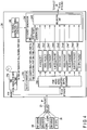
- FIG. 4 is a conceptual view illustrating a configuration example of the multiplexing apparatus 24 to which the synchronization control method and synchronization control apparatus of the first embodiment are applied.
- the multiplexing apparatus 24 includes a processor (not shown) and a program memory (not shown).
- the multiplexing apparatus 24 includes, as necessary control functions for implementing the present embodiment, a time reproduction unit 24a, a TAI/STC converter 24b, a PCR packet generation timing controller 24c, a PCR/video/audio/subtitle/SI • EPG separator 24d (hereinafter, simply referred to as "separator 24d”), and a TS packet generator 24f.
- These control functions are realized by causing the CPU to execute programs stored in the program memory.
- the TS packet generator 24f further includes a PCR packet generator 24f1 and a multiplexing unit 24f2.
- IP packets from the PTP server 60 and encoders 22 are input to the multiplexing apparatus 24 via an IP-SW 23 which is not shown in FIG. 1 or FIG. 2 .
- the IP packets are not limited to the IP packets which are output from the PTP server 60 and encoders 22, and may include IP packets output from an SI • EPG 26 which is not shown in FIG. 1 or FIG. 2 .
- the time reproduction unit 24a has the same configuration as the time reproduction unit 22a.
- the time reproduction unit 24a receives the PTP packet included in the input IP packet, samples TAI time at the time of receiving the PTP packet, and outputs the sampled TAI time to the TAI/STC converter 24b.
- the TAI/STC converter 24b has the same configuration as the TAI/STC converter 22b.
- the TAI/STC converter 24b converts the TAI time, which is output from the time reproduction unit 24a, to the STC counter value (PCR value) which is used for synchronization control between the systems.
- the STC counter value is used for synchronization control between the systems.
- the TAI/STC converter 24b operates as a synchronization control apparatus by which the synchronization control method of the present embodiment is implemented in the corresponding multiplexing apparatuses 24 of the working system 20A and auxiliary system 20B.
- the calculation procedure of the PCR value in the TAI/STC converter 24b is the same as the calculation procedure in the TAI/STC converter 22b, so an overlapping description is avoided.
- the TAI/STC converter 24b outputs the calculated PCR value to the PCR packet generator 24f1.
- the separator 24d extracts, for example, from video/audio such as TS over IP packets, a PCR packet 24e1, a video packet 24e2, an audio packet 24e3, a subtitle packet 24e4, a PCR packet 24e5, a video packet 24e6, an audio packet 24e7, a subtitle packet 24e8, and an SI • EPG packet 24e9, and outputs the extracted packets to the multiplexing unit 24f2.
- video/audio such as TS over IP packets
- a PCR packet 24e1 a video packet 24e2
- an audio packet 24e3 a subtitle packet 24e4
- a PCR packet 24e5 a video packet 24e6, an audio packet 24e7, a subtitle packet 24e8, and an SI • EPG packet 24e9
- the PCR packet generator 22f1 generates a PCR packet in accordance with the control by the PCR packet generation timing controller 24c, adds the PCR value, which is output from the TAI/STC converter 24b, to the generated PCR packet, and outputs the PCR packet to the multiplexing unit 24f2.
- the multiplexing unit 24f2 multiplexes the PCR packet which is output from the PCR packet generator 24f1, the PCR packet 24e1, video packet 24e2, audio packet 24e3, subtitle packet 24e4, PCR packet 24e5, video packet 24e6, audio packet 24e7, subtitle packet 24e8 and SI • EPG packet 24e9, and outputs the multiplexed packet.
- the time reproduction unit 22a, 24a and TAI/STC converter 22b, 24b are included in the encoder 22 and multiplexing apparatus 24. Thereby, while the apparatuses can be connected by only the Ethernet, the STC counter values can be synchronized.
- the compression multiplex system control apparatus 10 is free from the use of a coaxial cable. Thereby, it is not necessary to distribute signals by a plurality of coaxial cables (SDI, DVB-ASI).
- the synchronization of STC counter values is realized from the clock reproduced from the time information (PTP), in particular, in the encoder 22 and multiplexing apparatus 24 which are equipped with the time reproduction unit 22a, 24a and TAI/STC converter 22b, 24b.
- PTP time information
- the encoder 22 in the working system 20A and the corresponding encoder 22 in the auxiliary system 20B can be made to uniformly have identical STC counter values, and can be synchronized.
- the multiplexing apparatus 24 in the working system 20A and the multiplexing apparatus 24 in the auxiliary system 20B can be made to uniformly have identical STC counter values, and can be synchronized. Thereby, seamless system switching between the working system 20A and auxiliary system 20B can be realized.
- the time synchronization precision of the respective apparatuses can be improved by using the PTP (IP packet/Ethernet), and the STC counter values between the apparatuses can be synchronized based on the time information reproduced from the PTP. Therefore, seamless system switching can be realized by only the connection of the Ethernet cable.
- PTP IP packet/Ethernet
- the second embodiment is a modification of the first embodiment.
- the same structural parts as described in the first embodiment are denoted by the same reference numerals as used in the first embodiment, and an overlapping description is avoided. Different structural parts from the first embodiment will mainly be described.
- FIG. 5 is a conceptual view illustrating a configuration example of an encoder to which the synchronization control method and synchronization control apparatus of the second embodiment are applied.
- FIG. 6 is a conceptual view illustrating a configuration example of a multiplexing apparatus to which the synchronization control method and synchronization control apparatus of the second embodiment are applied.
- An encoder 22' shown in FIG. 5 is different from the encoder 22 shown in FIG. 3 in that a processor or dedicated arithmetic circuit (not shown) realizes an STC counter unit 22g in place of the TAI/STC converter 22b in the encoder 22 shown in FIG. 3 .
- a multiplexing apparatus 24' shown in FIG. 6 is different from the multiplexing apparatus 24 shown in FIG. 4 in that a processor or dedicated arithmetic circuit (not shown) realizes an STC counter unit 24g in place of the TAI/STC converter 24b in the multiplexing apparatus 24 shown in FIG. 4 .
- the STC counter unit 22g operates as a synchronization control apparatus by which the synchronization control method of the present embodiment is implemented in the corresponding encoders 22' of the working system 20A and auxiliary system 20B.
- the STC counter unit 24g operates as a synchronization control apparatus by which the synchronization control method of the present embodiment is implemented in the corresponding multiplexing apparatuses 24' of the working system 20A and auxiliary system 20B.
- the configuration of the STC counter unit 22g is identical to the configuration of the STC counter unit 24g, the configuration of the STC counter unit 22g will representatively be described below with reference to FIG. 7 .
- FIG. 7 is a functional block diagram illustrating detailed configuration examples of the STC counter unit 22g and time reproduction unit 22a provided in the front stage of the STC counter unit 22g, by which the synchronization control apparatus of the present embodiment is realized.
- the time reproduction unit 22a includes a phase comparator 22a1, a loop filter 22a2, a VCO (Voltage-controlled oscillator) 22a3, and a TAI time counter 22a4.
- the STC counter unit 22g includes a TAI/STC converter 22g1, a phase comparator 22g2, a loop filter 22g3, a VCO 22g4, a 27 MHz counter 22g5, and an STC counter 22g6.
- the STC counter unit 22g executes initial reset of the 27 MHz counter 22g5 when the decimal part of the TAI time becomes zero.
- the 27 MHz counter 22g5 counts up by the clock generated by the VCO 22g4 (the precision of 27 MHz ⁇ ⁇ ), and returns to zero when 27 M cycles have passed.
- the phase comparator 22g2 compares the phases of both counters (e.g. in every second).
- the 27 MHz counter 22g5 is fast, the oscillation frequency of the VCO 22g4 is lowered via the loop filter 22g3.
- the oscillation frequency of the VCO 22g4 is increased via the loop filter 22g3. This is the same as the operation of a general PLL.
- the TAI/STC converter 22g1 samples the TAI time, converts the sampled TAI time to an STC counter value, and loads the STC counter value as an initial value of the STC counter value. In this case, it is desirable to correct the initial value by giving consideration to a delay time necessary for conversion. Subsequently, the STC counter 22g6 operates at 27 MHz which is locked to the TAI time.
- the STC counter 22g6 is made to operate independently, and the initial value of the STC counter value is found from the TAI and loaded in the STC counter 22g6.
- the STC counter 22g6 operates at 27 MHz, the TAI time counter 22a4 is locked by PLL to the clock for TAI count (1 GHz or a division of 1 GHz) generated from the PTP packet, in order to find the TAI time in the TAI time counter 22a4.
- the STC counter 22g6 is not easy to handle, since the base of the 90 kHz operation is 33 bits and the extension of the 27 MHz operation is 9 bits (values are 0 ⁇ 299). Thus, for example, a counter which circles at 27M cycles is separately prepared, phase comparison is performed in every second (in every count-up of a second), and the VCO 22g4 (the precision of 27 MHz ⁇ ⁇ ) is controlled and locked.
- the STC counter 22g6 samples and uses STC counter values, when generating packets in which the PCR, PTS and DTS are contained.
- the STC counter unit 22g, 24g is provided, the initial value of the STC counter value is set from the TAI time, and the STC counter is made to operate independently.
- the STC counter values can be uniquely determined based on the time information reproduced from the PTP. Therefore, the STC counter values between the apparatuses can be synchronized by only the connection of the Ethernet cable, and thus seamless system switching can be realized.
- an encoder 22 and multiplexing apparatus 24 which are additionally equipped with a function of calculating, based on TAI time, an audio frame number, a video field number and a video frame number, will be described.
- FIG. 8 is a block diagram illustrating configuration examples of the time reproduction unit 22a, and an audio frame number calculator 22h, a video field number calculator 22i and a video frame number calculator 22j which are connected to the time reproduction unit 22a.
- the audio frame number calculator 22h, video field number calculator 22i and video frame number calculator 22j which are illustrated in FIG. 8 , are connected in parallel to the time reproduction unit 22a, and are provided in the encoder 22. Similarly, these may be connected to the time reproduction unit 24a and may thereby be provided in the multiplexing apparatus 24.
- the audio frame number calculator 22h, video field number calculator 22i and video frame number calculator 22j include dividers 22h1, 22i1 and 22j1 and round-to-integer units 22h2, 22i2 and 22j2, respectively.
- the divider 22h1, 22i1, 22j1 divides, by each period, the TAI time which is output by the TAI time counter 22a4 of the time reproduction unit 22a.
- the round-to-integer units 22h2, 22i2 and 22j2 set integer parts of quotients, which are obtained by the corresponding dividers 22h1, 22i1 and 22j1, as an audio frame number, a video field number and video frame number, respectively.
- the respective calculators may be configured by taking the arithmetic precision into account, such that as regards the audio frame number calculator 22h, in the case of 48 kHz, one audio frame period is set to be 1024/48000 seconds; as regards the video field number calculator 22i, in the case of a 59.94i signal, one video field period is set to be 1000/(30 ⁇ 1001) seconds; and as regards the video frame number calculator 22j, in the case of a 59.94i signal, one video frame period is set to be 1000/(30 ⁇ 1001) seconds.
- the audio frame number calculator 22h By properly providing the audio frame number calculator 22h, video field number calculator 22i and video frame number calculator 22j, the audio frame number, video field number and video frame number can also be calculated based on the TAI time.
Landscapes
- Engineering & Computer Science (AREA)
- Signal Processing (AREA)
- Multimedia (AREA)
- Theoretical Computer Science (AREA)
- Computer Networks & Wireless Communication (AREA)
- Physics & Mathematics (AREA)
- General Engineering & Computer Science (AREA)
- General Physics & Mathematics (AREA)
- Computer Security & Cryptography (AREA)
- Synchronisation In Digital Transmission Systems (AREA)
- Two-Way Televisions, Distribution Of Moving Picture Or The Like (AREA)
Applications Claiming Priority (1)
| Application Number | Priority Date | Filing Date | Title |
|---|---|---|---|
| JP2018077398A JP7030602B2 (ja) | 2018-04-13 | 2018-04-13 | 同期制御装置および同期制御方法 |
Publications (2)
| Publication Number | Publication Date |
|---|---|
| EP3554090A1 true EP3554090A1 (de) | 2019-10-16 |
| EP3554090B1 EP3554090B1 (de) | 2022-03-02 |
Family
ID=66379695
Family Applications (1)
| Application Number | Title | Priority Date | Filing Date |
|---|---|---|---|
| EP19168815.9A Active EP3554090B1 (de) | 2018-04-13 | 2019-04-12 | Synchronisationssteuerungsvorrichtung und synchronisationssteuerungsverfahren |
Country Status (4)
| Country | Link |
|---|---|
| US (1) | US10924258B2 (de) |
| EP (1) | EP3554090B1 (de) |
| JP (1) | JP7030602B2 (de) |
| CN (1) | CN110381343B (de) |
Cited By (1)
| Publication number | Priority date | Publication date | Assignee | Title |
|---|---|---|---|---|
| WO2025185825A1 (en) * | 2024-03-07 | 2025-09-12 | Ateliere Creative Technologies Ab | Proxy editing of data streams |
Families Citing this family (3)
| Publication number | Priority date | Publication date | Assignee | Title |
|---|---|---|---|---|
| JP7210272B2 (ja) | 2018-12-28 | 2023-01-23 | 株式会社東芝 | 放送システム、エンコーダ、多重化装置、多重化方法、系統切替装置、および同期制御装置 |
| JP7242389B2 (ja) | 2019-04-11 | 2023-03-20 | 株式会社東芝 | パケット生成装置および方法 |
| JP7359057B2 (ja) * | 2020-03-27 | 2023-10-11 | 住友電気工業株式会社 | Si送出装置、si送出システム、si送出方法およびsi送出システムの運用方法 |
Citations (4)
| Publication number | Priority date | Publication date | Assignee | Title |
|---|---|---|---|---|
| EP2150062A1 (de) * | 2008-07-28 | 2010-02-03 | Harris Corporation | Verbessertes Verfahren, System und Vorrichtung zur Synchronisation von Signalen |
| US20160029052A1 (en) * | 2012-02-10 | 2016-01-28 | British Broadcasting Corporation | Method And Apparatus For Converting Audio, Video And Control Signals |
| WO2017026248A1 (ja) | 2015-08-07 | 2017-02-16 | ソニー株式会社 | 受信装置、及び、データ処理方法 |
| EP3163787A1 (de) * | 2014-06-30 | 2017-05-03 | ZTE Corporation | Verfahren und vorrichtung zur kompensierung des zeitstempels einer uhr |
Family Cites Families (3)
| Publication number | Priority date | Publication date | Assignee | Title |
|---|---|---|---|---|
| JP4357070B2 (ja) | 2000-03-09 | 2009-11-04 | 株式会社東芝 | デジタル放送信号同期切替送出装置 |
| CN105959075B (zh) * | 2015-08-31 | 2018-02-13 | 地球公时时频技术开发有限责任公司 | 一种全宇信息平台以及基于该平台的智能系统同步方法 |
| JP6796233B2 (ja) * | 2016-09-05 | 2020-12-09 | 株式会社メディアリンクス | 映像切替システム |
-
2018
- 2018-04-13 JP JP2018077398A patent/JP7030602B2/ja active Active
-
2019
- 2019-04-12 EP EP19168815.9A patent/EP3554090B1/de active Active
- 2019-04-12 US US16/382,781 patent/US10924258B2/en active Active
- 2019-04-12 CN CN201910292568.8A patent/CN110381343B/zh active Active
Patent Citations (4)
| Publication number | Priority date | Publication date | Assignee | Title |
|---|---|---|---|---|
| EP2150062A1 (de) * | 2008-07-28 | 2010-02-03 | Harris Corporation | Verbessertes Verfahren, System und Vorrichtung zur Synchronisation von Signalen |
| US20160029052A1 (en) * | 2012-02-10 | 2016-01-28 | British Broadcasting Corporation | Method And Apparatus For Converting Audio, Video And Control Signals |
| EP3163787A1 (de) * | 2014-06-30 | 2017-05-03 | ZTE Corporation | Verfahren und vorrichtung zur kompensierung des zeitstempels einer uhr |
| WO2017026248A1 (ja) | 2015-08-07 | 2017-02-16 | ソニー株式会社 | 受信装置、及び、データ処理方法 |
Non-Patent Citations (1)
| Title |
|---|
| EBU ET AL: "Request for Standardization", 1 August 2009 (2009-08-01), pages 1 - 115, XP008113642, Retrieved from the Internet <URL:http://store.smpte.org/product-p/tfts%20rfs-2009.htm> [retrieved on 20090801] * |
Cited By (2)
| Publication number | Priority date | Publication date | Assignee | Title |
|---|---|---|---|---|
| WO2025185825A1 (en) * | 2024-03-07 | 2025-09-12 | Ateliere Creative Technologies Ab | Proxy editing of data streams |
| WO2025186239A1 (en) * | 2024-03-07 | 2025-09-12 | Ateliere Creative Technologies Ab | Proxy editing of data streams |
Also Published As
| Publication number | Publication date |
|---|---|
| CN110381343A (zh) | 2019-10-25 |
| CN110381343B (zh) | 2022-07-19 |
| US20190319776A1 (en) | 2019-10-17 |
| JP7030602B2 (ja) | 2022-03-07 |
| JP2019186812A (ja) | 2019-10-24 |
| EP3554090B1 (de) | 2022-03-02 |
| US10924258B2 (en) | 2021-02-16 |
Similar Documents
| Publication | Publication Date | Title |
|---|---|---|
| EP3554090B1 (de) | Synchronisationssteuerungsvorrichtung und synchronisationssteuerungsverfahren | |
| US11936713B2 (en) | Broadcasting system, encoder, multiplexing apparatus, multiplexing method, system switching apparatus, and synchronization control apparatus | |
| JP4240545B2 (ja) | デジタルデータフォーマット変換及びビットストリーム生成のためのシステム | |
| US20160366431A1 (en) | Video decoding device and video decoding method | |
| EP2058722B1 (de) | Signalverarbeitungsvorrichtung | |
| WO2014188960A1 (ja) | 送信装置、送信方法、受信装置および受信方法 | |
| KR100209880B1 (ko) | Mpeg-2 영상복호화장치의 시스템클럭 복구장치 | |
| JP2012513139A (ja) | 外部のコプロセッサを有するマルチプレクサにおいてトランスポートストリームを同期させる方法 | |
| JP6813933B2 (ja) | 映像音声伝送システム、伝送方法、送信装置及び受信装置 | |
| JPH11331639A (ja) | 放送スタジオの同期分配システム及び方法 | |
| JP3893643B2 (ja) | 信号多重化方法およびそれを用いた伝送信号生成装置 | |
| US11259070B2 (en) | Packet generation apparatus and method | |
| JP3888014B2 (ja) | 位相同期回路 | |
| JP4678109B2 (ja) | クロック発生装置及び方法 | |
| JP4387544B2 (ja) | デジタル放送信号送出システムのフレーム同期装置 | |
| EP2202976A1 (de) | Digitale Rundfunkempfangsvorrichtung und Signalverarbeitungsverfahren | |
| JP2001103026A (ja) | 複数エンコーダの同期方法およびその装置 | |
| KR100414638B1 (ko) | 데이터 전송률 산출 방법 및 송출 장치 | |
| JP6515741B2 (ja) | コンテンツ伝送システム、送信装置、送信方法、送信プログラム | |
| JP2014150335A (ja) | 情報処理装置、情報処理方法及びプログラム | |
| Machmerth et al. | Accumulator based PCR restamping | |
| KR19980060658A (ko) | Mpeg-2 시스템클럭 복원을 위한 디지탈 pll 회로 | |
| JP2010136320A (ja) | パケット送信装置および方法 | |
| WO2009010891A1 (en) | A method and a device for data sample clock reconstruction |
Legal Events
| Date | Code | Title | Description |
|---|---|---|---|
| PUAI | Public reference made under article 153(3) epc to a published international application that has entered the european phase |
Free format text: ORIGINAL CODE: 0009012 |
|
| STAA | Information on the status of an ep patent application or granted ep patent |
Free format text: STATUS: REQUEST FOR EXAMINATION WAS MADE |
|
| 17P | Request for examination filed |
Effective date: 20190412 |
|
| AK | Designated contracting states |
Kind code of ref document: A1 Designated state(s): AL AT BE BG CH CY CZ DE DK EE ES FI FR GB GR HR HU IE IS IT LI LT LU LV MC MK MT NL NO PL PT RO RS SE SI SK SM TR |
|
| AX | Request for extension of the european patent |
Extension state: BA ME |
|
| STAA | Information on the status of an ep patent application or granted ep patent |
Free format text: STATUS: EXAMINATION IS IN PROGRESS |
|
| 17Q | First examination report despatched |
Effective date: 20201019 |
|
| GRAP | Despatch of communication of intention to grant a patent |
Free format text: ORIGINAL CODE: EPIDOSNIGR1 |
|
| STAA | Information on the status of an ep patent application or granted ep patent |
Free format text: STATUS: GRANT OF PATENT IS INTENDED |
|
| INTG | Intention to grant announced |
Effective date: 20211001 |
|
| GRAS | Grant fee paid |
Free format text: ORIGINAL CODE: EPIDOSNIGR3 |
|
| GRAA | (expected) grant |
Free format text: ORIGINAL CODE: 0009210 |
|
| STAA | Information on the status of an ep patent application or granted ep patent |
Free format text: STATUS: THE PATENT HAS BEEN GRANTED |
|
| AK | Designated contracting states |
Kind code of ref document: B1 Designated state(s): AL AT BE BG CH CY CZ DE DK EE ES FI FR GB GR HR HU IE IS IT LI LT LU LV MC MK MT NL NO PL PT RO RS SE SI SK SM TR |
|
| REG | Reference to a national code |
Ref country code: GB Ref legal event code: FG4D |
|
| REG | Reference to a national code |
Ref country code: CH Ref legal event code: EP Ref country code: AT Ref legal event code: REF Ref document number: 1473242 Country of ref document: AT Kind code of ref document: T Effective date: 20220315 |
|
| REG | Reference to a national code |
Ref country code: DE Ref legal event code: R096 Ref document number: 602019012004 Country of ref document: DE |
|
| REG | Reference to a national code |
Ref country code: IE Ref legal event code: FG4D |
|
| REG | Reference to a national code |
Ref country code: LT Ref legal event code: MG9D |
|
| REG | Reference to a national code |
Ref country code: NL Ref legal event code: MP Effective date: 20220302 |
|
| PG25 | Lapsed in a contracting state [announced via postgrant information from national office to epo] |
Ref country code: SE Free format text: LAPSE BECAUSE OF FAILURE TO SUBMIT A TRANSLATION OF THE DESCRIPTION OR TO PAY THE FEE WITHIN THE PRESCRIBED TIME-LIMIT Effective date: 20220302 Ref country code: RS Free format text: LAPSE BECAUSE OF FAILURE TO SUBMIT A TRANSLATION OF THE DESCRIPTION OR TO PAY THE FEE WITHIN THE PRESCRIBED TIME-LIMIT Effective date: 20220302 Ref country code: NO Free format text: LAPSE BECAUSE OF FAILURE TO SUBMIT A TRANSLATION OF THE DESCRIPTION OR TO PAY THE FEE WITHIN THE PRESCRIBED TIME-LIMIT Effective date: 20220602 Ref country code: LT Free format text: LAPSE BECAUSE OF FAILURE TO SUBMIT A TRANSLATION OF THE DESCRIPTION OR TO PAY THE FEE WITHIN THE PRESCRIBED TIME-LIMIT Effective date: 20220302 Ref country code: HR Free format text: LAPSE BECAUSE OF FAILURE TO SUBMIT A TRANSLATION OF THE DESCRIPTION OR TO PAY THE FEE WITHIN THE PRESCRIBED TIME-LIMIT Effective date: 20220302 Ref country code: ES Free format text: LAPSE BECAUSE OF FAILURE TO SUBMIT A TRANSLATION OF THE DESCRIPTION OR TO PAY THE FEE WITHIN THE PRESCRIBED TIME-LIMIT Effective date: 20220302 Ref country code: BG Free format text: LAPSE BECAUSE OF FAILURE TO SUBMIT A TRANSLATION OF THE DESCRIPTION OR TO PAY THE FEE WITHIN THE PRESCRIBED TIME-LIMIT Effective date: 20220602 |
|
| REG | Reference to a national code |
Ref country code: AT Ref legal event code: MK05 Ref document number: 1473242 Country of ref document: AT Kind code of ref document: T Effective date: 20220302 |
|
| PG25 | Lapsed in a contracting state [announced via postgrant information from national office to epo] |
Ref country code: PL Free format text: LAPSE BECAUSE OF FAILURE TO SUBMIT A TRANSLATION OF THE DESCRIPTION OR TO PAY THE FEE WITHIN THE PRESCRIBED TIME-LIMIT Effective date: 20220302 Ref country code: LV Free format text: LAPSE BECAUSE OF FAILURE TO SUBMIT A TRANSLATION OF THE DESCRIPTION OR TO PAY THE FEE WITHIN THE PRESCRIBED TIME-LIMIT Effective date: 20220302 Ref country code: GR Free format text: LAPSE BECAUSE OF FAILURE TO SUBMIT A TRANSLATION OF THE DESCRIPTION OR TO PAY THE FEE WITHIN THE PRESCRIBED TIME-LIMIT Effective date: 20220603 Ref country code: FI Free format text: LAPSE BECAUSE OF FAILURE TO SUBMIT A TRANSLATION OF THE DESCRIPTION OR TO PAY THE FEE WITHIN THE PRESCRIBED TIME-LIMIT Effective date: 20220302 |
|
| PG25 | Lapsed in a contracting state [announced via postgrant information from national office to epo] |
Ref country code: NL Free format text: LAPSE BECAUSE OF FAILURE TO SUBMIT A TRANSLATION OF THE DESCRIPTION OR TO PAY THE FEE WITHIN THE PRESCRIBED TIME-LIMIT Effective date: 20220302 |
|
| PG25 | Lapsed in a contracting state [announced via postgrant information from national office to epo] |
Ref country code: SM Free format text: LAPSE BECAUSE OF FAILURE TO SUBMIT A TRANSLATION OF THE DESCRIPTION OR TO PAY THE FEE WITHIN THE PRESCRIBED TIME-LIMIT Effective date: 20220302 Ref country code: SK Free format text: LAPSE BECAUSE OF FAILURE TO SUBMIT A TRANSLATION OF THE DESCRIPTION OR TO PAY THE FEE WITHIN THE PRESCRIBED TIME-LIMIT Effective date: 20220302 Ref country code: RO Free format text: LAPSE BECAUSE OF FAILURE TO SUBMIT A TRANSLATION OF THE DESCRIPTION OR TO PAY THE FEE WITHIN THE PRESCRIBED TIME-LIMIT Effective date: 20220302 Ref country code: PT Free format text: LAPSE BECAUSE OF FAILURE TO SUBMIT A TRANSLATION OF THE DESCRIPTION OR TO PAY THE FEE WITHIN THE PRESCRIBED TIME-LIMIT Effective date: 20220704 Ref country code: EE Free format text: LAPSE BECAUSE OF FAILURE TO SUBMIT A TRANSLATION OF THE DESCRIPTION OR TO PAY THE FEE WITHIN THE PRESCRIBED TIME-LIMIT Effective date: 20220302 Ref country code: CZ Free format text: LAPSE BECAUSE OF FAILURE TO SUBMIT A TRANSLATION OF THE DESCRIPTION OR TO PAY THE FEE WITHIN THE PRESCRIBED TIME-LIMIT Effective date: 20220302 Ref country code: AT Free format text: LAPSE BECAUSE OF FAILURE TO SUBMIT A TRANSLATION OF THE DESCRIPTION OR TO PAY THE FEE WITHIN THE PRESCRIBED TIME-LIMIT Effective date: 20220302 |
|
| PG25 | Lapsed in a contracting state [announced via postgrant information from national office to epo] |
Ref country code: IS Free format text: LAPSE BECAUSE OF FAILURE TO SUBMIT A TRANSLATION OF THE DESCRIPTION OR TO PAY THE FEE WITHIN THE PRESCRIBED TIME-LIMIT Effective date: 20220702 Ref country code: AL Free format text: LAPSE BECAUSE OF FAILURE TO SUBMIT A TRANSLATION OF THE DESCRIPTION OR TO PAY THE FEE WITHIN THE PRESCRIBED TIME-LIMIT Effective date: 20220302 |
|
| REG | Reference to a national code |
Ref country code: CH Ref legal event code: PL |
|
| REG | Reference to a national code |
Ref country code: DE Ref legal event code: R097 Ref document number: 602019012004 Country of ref document: DE |
|
| REG | Reference to a national code |
Ref country code: BE Ref legal event code: MM Effective date: 20220430 |
|
| PLBE | No opposition filed within time limit |
Free format text: ORIGINAL CODE: 0009261 |
|
| STAA | Information on the status of an ep patent application or granted ep patent |
Free format text: STATUS: NO OPPOSITION FILED WITHIN TIME LIMIT |
|
| PG25 | Lapsed in a contracting state [announced via postgrant information from national office to epo] |
Ref country code: MC Free format text: LAPSE BECAUSE OF FAILURE TO SUBMIT A TRANSLATION OF THE DESCRIPTION OR TO PAY THE FEE WITHIN THE PRESCRIBED TIME-LIMIT Effective date: 20220302 Ref country code: LU Free format text: LAPSE BECAUSE OF NON-PAYMENT OF DUE FEES Effective date: 20220412 Ref country code: LI Free format text: LAPSE BECAUSE OF NON-PAYMENT OF DUE FEES Effective date: 20220430 Ref country code: DK Free format text: LAPSE BECAUSE OF FAILURE TO SUBMIT A TRANSLATION OF THE DESCRIPTION OR TO PAY THE FEE WITHIN THE PRESCRIBED TIME-LIMIT Effective date: 20220302 Ref country code: CH Free format text: LAPSE BECAUSE OF NON-PAYMENT OF DUE FEES Effective date: 20220430 |
|
| 26N | No opposition filed |
Effective date: 20221205 |
|
| PG25 | Lapsed in a contracting state [announced via postgrant information from national office to epo] |
Ref country code: SI Free format text: LAPSE BECAUSE OF FAILURE TO SUBMIT A TRANSLATION OF THE DESCRIPTION OR TO PAY THE FEE WITHIN THE PRESCRIBED TIME-LIMIT Effective date: 20220302 Ref country code: BE Free format text: LAPSE BECAUSE OF NON-PAYMENT OF DUE FEES Effective date: 20220430 |
|
| PG25 | Lapsed in a contracting state [announced via postgrant information from national office to epo] |
Ref country code: IE Free format text: LAPSE BECAUSE OF NON-PAYMENT OF DUE FEES Effective date: 20220412 |
|
| PG25 | Lapsed in a contracting state [announced via postgrant information from national office to epo] |
Ref country code: IT Free format text: LAPSE BECAUSE OF FAILURE TO SUBMIT A TRANSLATION OF THE DESCRIPTION OR TO PAY THE FEE WITHIN THE PRESCRIBED TIME-LIMIT Effective date: 20220302 |
|
| PG25 | Lapsed in a contracting state [announced via postgrant information from national office to epo] |
Ref country code: HU Free format text: LAPSE BECAUSE OF FAILURE TO SUBMIT A TRANSLATION OF THE DESCRIPTION OR TO PAY THE FEE WITHIN THE PRESCRIBED TIME-LIMIT; INVALID AB INITIO Effective date: 20190412 |
|
| PG25 | Lapsed in a contracting state [announced via postgrant information from national office to epo] |
Ref country code: MK Free format text: LAPSE BECAUSE OF FAILURE TO SUBMIT A TRANSLATION OF THE DESCRIPTION OR TO PAY THE FEE WITHIN THE PRESCRIBED TIME-LIMIT Effective date: 20220302 Ref country code: CY Free format text: LAPSE BECAUSE OF FAILURE TO SUBMIT A TRANSLATION OF THE DESCRIPTION OR TO PAY THE FEE WITHIN THE PRESCRIBED TIME-LIMIT Effective date: 20220302 |
|
| PG25 | Lapsed in a contracting state [announced via postgrant information from national office to epo] |
Ref country code: TR Free format text: LAPSE BECAUSE OF FAILURE TO SUBMIT A TRANSLATION OF THE DESCRIPTION OR TO PAY THE FEE WITHIN THE PRESCRIBED TIME-LIMIT Effective date: 20220302 |
|
| PG25 | Lapsed in a contracting state [announced via postgrant information from national office to epo] |
Ref country code: MT Free format text: LAPSE BECAUSE OF FAILURE TO SUBMIT A TRANSLATION OF THE DESCRIPTION OR TO PAY THE FEE WITHIN THE PRESCRIBED TIME-LIMIT Effective date: 20220302 |
|
| PGFP | Annual fee paid to national office [announced via postgrant information from national office to epo] |
Ref country code: DE Payment date: 20250225 Year of fee payment: 7 |
|
| REG | Reference to a national code |
Ref country code: DE Ref legal event code: R081 Ref document number: 602019012004 Country of ref document: DE Owner name: KABUSHIKI KAISHA TOSHIBA, JP Free format text: FORMER OWNERS: KABUSHIKI KAISHA TOSHIBA, TOKYO, JP; TOSHIBA INFRASTRUCTURE SYSTEMS & SOLUTIONS CORPORATION, KAWASAKI-SHI, KANAGAWA, JP |
|
| REG | Reference to a national code |
Ref country code: GB Ref legal event code: 732E Free format text: REGISTERED BETWEEN 20260212 AND 20260218 |
|
| PGFP | Annual fee paid to national office [announced via postgrant information from national office to epo] |
Ref country code: GB Payment date: 20260303 Year of fee payment: 8 |
|
| PGFP | Annual fee paid to national office [announced via postgrant information from national office to epo] |
Ref country code: FR Payment date: 20260223 Year of fee payment: 8 |