EP3554029B1 - Physical broadcast channel (pbch) transmission for reliable detection of antenna configuration - Google Patents
Physical broadcast channel (pbch) transmission for reliable detection of antenna configuration Download PDFInfo
- Publication number
- EP3554029B1 EP3554029B1 EP19175569.3A EP19175569A EP3554029B1 EP 3554029 B1 EP3554029 B1 EP 3554029B1 EP 19175569 A EP19175569 A EP 19175569A EP 3554029 B1 EP3554029 B1 EP 3554029B1
- Authority
- EP
- European Patent Office
- Prior art keywords
- transmit antennas
- crc
- block
- data
- masking
- Prior art date
- Legal status (The legal status is an assumption and is not a legal conclusion. Google has not performed a legal analysis and makes no representation as to the accuracy of the status listed.)
- Active
Links
- 230000005540 biological transmission Effects 0.000 title claims description 45
- 238000001514 detection method Methods 0.000 title description 3
- 230000000873 masking effect Effects 0.000 claims description 26
- 238000000034 method Methods 0.000 claims description 25
- 238000004891 communication Methods 0.000 claims description 16
- 125000004122 cyclic group Chemical group 0.000 claims description 11
- 230000010363 phase shift Effects 0.000 claims description 6
- 238000013507 mapping Methods 0.000 description 64
- 238000010586 diagram Methods 0.000 description 13
- 238000012937 correction Methods 0.000 description 5
- 230000008859 change Effects 0.000 description 4
- 238000012360 testing method Methods 0.000 description 3
- 101000741965 Homo sapiens Inactive tyrosine-protein kinase PRAG1 Proteins 0.000 description 2
- 102100038659 Inactive tyrosine-protein kinase PRAG1 Human genes 0.000 description 2
- 238000012986 modification Methods 0.000 description 2
- 230000004048 modification Effects 0.000 description 2
- 230000008569 process Effects 0.000 description 2
- 108010076504 Protein Sorting Signals Proteins 0.000 description 1
- 238000013459 approach Methods 0.000 description 1
- 239000000969 carrier Substances 0.000 description 1
- 238000006243 chemical reaction Methods 0.000 description 1
- 238000009432 framing Methods 0.000 description 1
- 230000006872 improvement Effects 0.000 description 1
- 238000007620 mathematical function Methods 0.000 description 1
- 230000007246 mechanism Effects 0.000 description 1
- 239000000203 mixture Substances 0.000 description 1
- 230000009467 reduction Effects 0.000 description 1
- 238000001228 spectrum Methods 0.000 description 1
- 230000009466 transformation Effects 0.000 description 1
Images


Classifications
-
- H—ELECTRICITY
- H04—ELECTRIC COMMUNICATION TECHNIQUE
- H04B—TRANSMISSION
- H04B7/00—Radio transmission systems, i.e. using radiation field
- H04B7/02—Diversity systems; Multi-antenna system, i.e. transmission or reception using multiple antennas
- H04B7/04—Diversity systems; Multi-antenna system, i.e. transmission or reception using multiple antennas using two or more spaced independent antennas
- H04B7/06—Diversity systems; Multi-antenna system, i.e. transmission or reception using multiple antennas using two or more spaced independent antennas at the transmitting station
- H04B7/0613—Diversity systems; Multi-antenna system, i.e. transmission or reception using multiple antennas using two or more spaced independent antennas at the transmitting station using simultaneous transmission
- H04B7/0615—Diversity systems; Multi-antenna system, i.e. transmission or reception using multiple antennas using two or more spaced independent antennas at the transmitting station using simultaneous transmission of weighted versions of same signal
- H04B7/0619—Diversity systems; Multi-antenna system, i.e. transmission or reception using multiple antennas using two or more spaced independent antennas at the transmitting station using simultaneous transmission of weighted versions of same signal using feedback from receiving side
- H04B7/0658—Feedback reduction
- H04B7/066—Combined feedback for a number of channels, e.g. over several subcarriers like in orthogonal frequency division multiplexing [OFDM]
-
- H—ELECTRICITY
- H04—ELECTRIC COMMUNICATION TECHNIQUE
- H04B—TRANSMISSION
- H04B1/00—Details of transmission systems, not covered by a single one of groups H04B3/00 - H04B13/00; Details of transmission systems not characterised by the medium used for transmission
- H04B1/005—Details of transmission systems, not covered by a single one of groups H04B3/00 - H04B13/00; Details of transmission systems not characterised by the medium used for transmission adapting radio receivers, transmitters andtransceivers for operation on two or more bands, i.e. frequency ranges
- H04B1/0053—Details of transmission systems, not covered by a single one of groups H04B3/00 - H04B13/00; Details of transmission systems not characterised by the medium used for transmission adapting radio receivers, transmitters andtransceivers for operation on two or more bands, i.e. frequency ranges with common antenna for more than one band
-
- H—ELECTRICITY
- H03—ELECTRONIC CIRCUITRY
- H03M—CODING; DECODING; CODE CONVERSION IN GENERAL
- H03M13/00—Coding, decoding or code conversion, for error detection or error correction; Coding theory basic assumptions; Coding bounds; Error probability evaluation methods; Channel models; Simulation or testing of codes
- H03M13/03—Error detection or forward error correction by redundancy in data representation, i.e. code words containing more digits than the source words
- H03M13/05—Error detection or forward error correction by redundancy in data representation, i.e. code words containing more digits than the source words using block codes, i.e. a predetermined number of check bits joined to a predetermined number of information bits
- H03M13/09—Error detection only, e.g. using cyclic redundancy check [CRC] codes or single parity bit
-
- H—ELECTRICITY
- H04—ELECTRIC COMMUNICATION TECHNIQUE
- H04B—TRANSMISSION
- H04B1/00—Details of transmission systems, not covered by a single one of groups H04B3/00 - H04B13/00; Details of transmission systems not characterised by the medium used for transmission
- H04B1/38—Transceivers, i.e. devices in which transmitter and receiver form a structural unit and in which at least one part is used for functions of transmitting and receiving
- H04B1/40—Circuits
-
- H—ELECTRICITY
- H04—ELECTRIC COMMUNICATION TECHNIQUE
- H04L—TRANSMISSION OF DIGITAL INFORMATION, e.g. TELEGRAPHIC COMMUNICATION
- H04L1/00—Arrangements for detecting or preventing errors in the information received
- H04L1/0001—Systems modifying transmission characteristics according to link quality, e.g. power backoff
- H04L1/0023—Systems modifying transmission characteristics according to link quality, e.g. power backoff characterised by the signalling
- H04L1/0028—Formatting
-
- H—ELECTRICITY
- H04—ELECTRIC COMMUNICATION TECHNIQUE
- H04L—TRANSMISSION OF DIGITAL INFORMATION, e.g. TELEGRAPHIC COMMUNICATION
- H04L27/00—Modulated-carrier systems
- H04L27/18—Phase-modulated carrier systems, i.e. using phase-shift keying
-
- H—ELECTRICITY
- H04—ELECTRIC COMMUNICATION TECHNIQUE
- H04L—TRANSMISSION OF DIGITAL INFORMATION, e.g. TELEGRAPHIC COMMUNICATION
- H04L27/00—Modulated-carrier systems
- H04L27/26—Systems using multi-frequency codes
- H04L27/2601—Multicarrier modulation systems
- H04L27/2626—Arrangements specific to the transmitter only
- H04L27/2627—Modulators
-
- H—ELECTRICITY
- H04—ELECTRIC COMMUNICATION TECHNIQUE
- H04L—TRANSMISSION OF DIGITAL INFORMATION, e.g. TELEGRAPHIC COMMUNICATION
- H04L27/00—Modulated-carrier systems
- H04L27/32—Carrier systems characterised by combinations of two or more of the types covered by groups H04L27/02, H04L27/10, H04L27/18 or H04L27/26
- H04L27/34—Amplitude- and phase-modulated carrier systems, e.g. quadrature-amplitude modulated carrier systems
-
- H—ELECTRICITY
- H04—ELECTRIC COMMUNICATION TECHNIQUE
- H04L—TRANSMISSION OF DIGITAL INFORMATION, e.g. TELEGRAPHIC COMMUNICATION
- H04L5/00—Arrangements affording multiple use of the transmission path
- H04L5/0001—Arrangements for dividing the transmission path
- H04L5/0003—Two-dimensional division
- H04L5/0005—Time-frequency
- H04L5/0007—Time-frequency the frequencies being orthogonal, e.g. OFDM(A), DMT
-
- H—ELECTRICITY
- H04—ELECTRIC COMMUNICATION TECHNIQUE
- H04W—WIRELESS COMMUNICATION NETWORKS
- H04W28/00—Network traffic management; Network resource management
- H04W28/02—Traffic management, e.g. flow control or congestion control
- H04W28/04—Error control
-
- H—ELECTRICITY
- H04—ELECTRIC COMMUNICATION TECHNIQUE
- H04W—WIRELESS COMMUNICATION NETWORKS
- H04W4/00—Services specially adapted for wireless communication networks; Facilities therefor
- H04W4/06—Selective distribution of broadcast services, e.g. multimedia broadcast multicast service [MBMS]; Services to user groups; One-way selective calling services
-
- H—ELECTRICITY
- H04—ELECTRIC COMMUNICATION TECHNIQUE
- H04W—WIRELESS COMMUNICATION NETWORKS
- H04W84/00—Network topologies
- H04W84/02—Hierarchically pre-organised networks, e.g. paging networks, cellular networks, WLAN [Wireless Local Area Network] or WLL [Wireless Local Loop]
- H04W84/04—Large scale networks; Deep hierarchical networks
- H04W84/042—Public Land Mobile systems, e.g. cellular systems
-
- H—ELECTRICITY
- H04—ELECTRIC COMMUNICATION TECHNIQUE
- H04W—WIRELESS COMMUNICATION NETWORKS
- H04W88/00—Devices specially adapted for wireless communication networks, e.g. terminals, base stations or access point devices
- H04W88/08—Access point devices
Definitions
- the present application relates generally to wireless communications and, more specifically, to a technique for improved interference power estimation.
- Modern communication systems include transceivers that comprise a plurality of antennas arranged in a plurality of configurations.
- information relating to the configuration of the antennas needs to be communicated to the device communicating with the transceiver.
- this communication requires considerable bandwidth and is not easily done.
- the conveyance of the configuration of the antennas represents significant overhead to a communication system. Therefore, there is a need in the art for an improved system and method for conveying antenna configuration information.
- systems and methods for transmitting data related to the configuration of transmit antennas may include obtaining a data for transmission, encoding the data and modulating the data. During the modulating of the data, the data may be configured in such a way as to convey the configuration of the data through the modulation of the data. These methods may also include obtaining an antenna configuration, obtaining a representation of the antenna configuration, and masking the data with an error correcting code, where the mask corresponds to the antenna configuration.
- a wireless communication network comprising a plurality of base stations capable of wireless communication with a plurality of subscriber stations within a coverage area of the network.
- at least one of the plurality of base stations is capable of encoding a transmission antenna configuration into a QPSK constellation and transmitting the QPSK constellation.
- the transmission may be masked with an error correction code that corresponds to a transmit antenna configuration.
- systems and methods are disclosed with a base station capable of wireless communication with a plurality of subscriber stations within a coverage area of a network.
- the base station is capable of transmitting data with at least one antenna, encoding a configuration of the at least one antenna into a data stream, and transmitting the data stream.
- These methods may further comprise transmitting an error correction code that has been masked to represent the configuration of the transmit antennas.
- FIGURES 1 through 16 discussed below, and the various embodiments used to describe the principles of the present disclosure in this patent document are by way of illustration only and should not be construed in any way to limit the scope of the disclosure. Those skilled in the art will understand that the principles of the present disclosure may be implemented in any suitably arranged wireless communication system.
- FIGURE 1 illustrates exemplary wireless network 100, which transmits ACK/NACK messages according to the principles of the present disclosure.
- wireless network 100 includes base station (BS) 101, base station (BS) 102, base station (BS) 103, and other similar base stations (not shown).
- Base station 101 is in communication with base station 102 and base station 103.
- Base station 101 is also in communication with Internet 130 or a similar IP-based network (not shown).
- Base station 102 provides wireless broadband access (via base station 101) to Internet 130 to a first plurality of subscriber stations within coverage area 120 of base station 102.
- the first plurality of subscriber stations includes subscriber station 111, which may be located in a small business (SB), subscriber station 112, which may be located in an enterprise (E), subscriber station 113, which may be located in a WiFi hotspot (HS), subscriber station 114, which may be located in a first residence (R), subscriber station 115, which may be located in a second residence (R), and subscriber station 116, which may be a mobile device (M), such as a cell phone, a wireless laptop, a wireless PDA, or the like.
- SB small business
- E enterprise
- HS WiFi hotspot
- R first residence
- subscriber station 116 which may be a mobile device (M), such as a cell phone, a wireless laptop, a wireless PDA, or
- Base station 103 provides wireless broadband access (via base station 101) to Internet 130 to a second plurality of subscriber stations within coverage area 125 of base station 103.
- the second plurality of subscriber stations includes subscriber station 115 and subscriber station 116.
- base stations 101-103 may communicate with each other and with subscriber stations 111-116 using OFDM or OFDMA techniques.
- Base station 101 may be in communication with either a greater number or a lesser number of base stations. Furthermore, while only six subscriber stations are depicted in FIGURE 1 , it is understood that wireless network 100 may provide wireless broadband access to additional subscriber stations. It is noted that subscriber station 115 and subscriber station 116 are located on the edges of both coverage area 120 and coverage area 125. Subscriber station 115 and subscriber station 116 each communicate with both base station 102 and base station 103 and may be said to be operating in handoff mode, as known to those of skill in the art.
- Subscriber stations 111-116 may access voice, data, video, video conferencing, and/or other broadband services via Internet 130.
- one or more of subscriber stations 111-116 may be associated with an access point (AP) of a WiFi WLAN.
- Subscriber station 116 may be any of a number of mobile devices, including a wireless-enabled laptop computer, personal data assistant, notebook, handheld device, or other wireless-enabled device.
- Subscriber stations 114 and 115 may be, for example, a wireless-enabled personal computer (PC), a laptop computer, a gateway, or another device.
- FIGURE 2 is a high-level diagram of an orthogonal frequency division multiple access (OFDMA) transmit path.
- FIGURE 3 is a high-level diagram of an orthogonal frequency division multiple access (OFDMA) receive path.
- the OFDMA transmit path is implemented in base station (BS) 102 and the OFDMA receive path is implemented in subscriber station (SS) 116 for the purposes of illustration and explanation only.
- BS base station
- SS subscriber station
- the OFDMA receive path may also be implemented in BS 102 and the OFDMA transmit path may be implemented in SS 116.
- the transmit path in BS 102 comprises channel coding and modulation block 205, serial-to-parallel (S-to-P) block 210, Size N Inverse Fast Fourier Transform (IFFT) block 215, parallel-to-serial (P-to-S) block 220, add cyclic prefix block 225, up-converter (UC) 230.
- the receive path in SS 116 comprises down-converter (DC) 255, remove cyclic prefix block 260, serial-to-parallel (S-to-P) block 265, Size N Fast Fourier Transform (FFT) block 270, parallel-to-serial (P-to-S) block 275, channel decoding and demodulation block 280.
- DC down-converter
- FFT Fast Fourier Transform
- FIGURES 2 and 3 may be implemented in software while other components may be implemented by configurable hardware or a mixture of software and configurable hardware.
- the FFT blocks and the IFFT blocks described in this disclosure document may be implemented as configurable software algorithms, where the value of Size N may be modified according to the implementation.
- the value of the N variable may be any integer number (i.e., 1, 2, 3, 4, etc.), while for FFT and IFFT functions, the value of the N variable may be any integer number that is a power of two (i.e., 1, 2, 4, 8, 16, etc.).
- channel coding and modulation block 205 receives a set of information bits, applies coding (e.g., Turbo coding) and modulates (e.g., QPSK, QAM) the input bits to produce a sequence of frequency-domain modulation symbols.
- Serial-to-parallel block 210 converts (i.e., de-multiplexes) the serial modulated symbols to parallel data to produce N parallel symbol streams where N is the IFFT/FFT size used in BS 102 and SS 116.
- Size N IFFT block 215 then performs an IFFT operation on the N parallel symbol streams to produce time-domain output signals.
- Parallel-to-serial block 220 converts (i.e., multiplexes) the parallel time-domain output symbols from Size N IFFT block 215 to produce a serial time-domain signal.
- Add cyclic prefix block 225 then inserts a cyclic prefix to the time-domain signal.
- up-converter 230 modulates (i.e., up-converts) the output of add cyclic prefix block 225 to RF frequency for transmission via a wireless channel.
- the signal may also be filtered at baseband before conversion to RF frequency.
- the transmitted RF signal arrives at SS 116 after passing through the wireless channel and reverse operations to those at BS 102 are performed.
- Down-converter 255 down-converts the received signal to baseband frequency and remove cyclic prefix block 260 removes the cyclic prefix to produce the serial time-domain baseband signal.
- Serial-to-parallel block 265 converts the time-domain baseband signal to parallel time domain signals.
- Size N FFT block 270 then performs an FFT algorithm to produce N parallel frequency-domain signals.
- Parallel-to-serial block 275 converts the parallel frequency-domain signals to a sequence of modulated data symbols.
- Channel decoding and demodulation block 280 demodulates and then decodes the modulated symbols to recover the original input data stream.
- Each of base stations 101-103 may implement a transmit path that is analogous to transmitting in the downlink to subscriber stations 111-116 and may implement a receive path that is analogous to receiving in the uplink from subscriber stations 111-116.
- each one of subscriber stations 111-116 may implement a transmit path corresponding to the architecture for transmitting in the uplink to base stations 101-103 and may implement a receive path corresponding to the architecture for receiving in the downlink from base stations 101-103.
- the present disclosure describes methods and systems to convey information relating to base station configuration to subscriber stations and, more specifically, to relaying base station antenna configuration to subscriber stations.
- This information can be conveyed through a plurality of methods, including placing antenna configuration into a quadrature-phase shift keying (QPSK) constellation (e.g., n-quadrature amplitude modulation (QAM) signal, wherein n is 2 ⁇ x) and placing antenna configuration into the error correction data (e.g., cyclic redundancy check (CRC) data).
- QPSK quadrature-phase shift keying
- QAM quadrature-phase shift keying
- QAM quadrature amplitude modulation
- CRC cyclic redundancy check
- QAM is a modulation scheme which conveys data by modulating the amplitude of two carrier waves. These two waves are referred to as quadrature carriers, and are generally out of phase with each other by 90 degrees.
- QAM may be represented by a constellation that comprises 2 ⁇ x points, where x is an integer greater than 1.
- the constellations discussed will be four point constellations (4-QAM).
- 4-QAM constellation a 2 dimensional graph is represented with one point in each quadrant of the 2 dimensional graph.
- additional information e.g., reference power signal
- the transmitter within base stations 101-103 performs a plurality of functions prior to actually transmitting data.
- QAM modulated symbols are serial-to-parallel converted and input to an inverse fast Fourier transform (IFFT) .
- IFFT inverse fast Fourier transform
- N time-domain samples are obtained.
- N refers to the IFFT/ fast Fourier transform (FFT) size used by the OFDM system.
- FFT fast Fourier transform
- the signal after IFFT is parallel-to-serial converted and a cyclic prefix (CP) is added to the signal sequence.
- the resulting sequence of samples is referred to as an OFDM symbol.
- this process is reversed, and the cyclic prefix is first removed. Then the signal is serial-to-parallel converted before being fed into the FFT. The output of the FFT is parallel-to-serial converted, and the resulting QAM modulation symbols are input to the QAM demodulator.
- the total bandwidth in an OFDM system is divided into narrowband frequency units called subcarriers.
- the number of subcarriers is equal to the FFT/IFFT size N used in the system.
- the number of subcarriers used for data is less than N because some subcarriers at the edge of the frequency spectrum are reserved as guard subcarriers. In general, no information is transmitted on guard subcarriers.
- the coded BCH transport block is mapped to four subframes (subframes #0, #1, #2,and #3) within a 40 ms interval.
- the coded broadcast channel (BCH) transport block is mapped to 4 OFDM symbols within a subframe.
- three base stations 101-103 antenna configurations will be used as examples herein. These configurations are one transmission antenna, two transmission antennas using a space frequency block coding (SFBC) transmission scheme, and four transmission antennas using SFBC - frequency switching transmission diversity (FSTD) transmission scheme. While different transmissions schemes are used, detecting the number of transmission antennas based upon the schemes is difficult. Each transmission scheme has a large portion of the signal which can be considered as a subset of the other schemes, and therefore it is difficult to reliably detect and determine the scheme being used based upon the signal. Therefore, the antenna configuration will need to be encoded either into the physical broadcast channel (P-BCH) transport block and related QAM constellation or the error correction data of the P-BCH transport block.
- P-BCH physical broadcast channel
- the 4-QAM constellation comprises four separate points that are distributed into the four quadrants of a two-dimensional mapping.
- Table 1 Constellation Mapping b ( i ) , b ( i +1) I Q 00 1 / 2 1 / 2 01 1 / 2 ⁇ 1 / 2 10 ⁇ 1 / 2 1 / 2 11 ⁇ 1 / 2 ⁇ 1 / 2
- a transmission chain is a series of operations preformed to prepare data for transmission. These operations may include scrambling, modulating, and mapping data. Transmission chains may be used consistent with a plurality of communication techniques, including orthogonal frequency division multiplexing (OFDM).
- OFDM orthogonal frequency division multiplexing
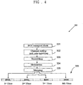
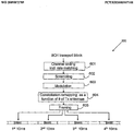
- FIGURE 4 a transmission chain of broadcast channel (BCH) mapped data across a predetermined time interval is illustrated by FIGURE 4 . It is understood that the examples disclosed relating to the encoding of data disclosed herein range from 10ms-40ms, but that any time interval may be used consistent with the disclosed systems and methods.
- BCH broadcast channel
- FIGURE 4 is an example of a method that may be used consistent with this disclosure to encode data.
- FIGURE 4 is a high level description of the transmission of a BCH transport block.
- the P-BCH is received by the mapping mechanism in a BCH transport block (Block 301).
- Channel coding which includes rate matching is applied to the BCH transport block(Block 302).
- the data may be modified to embed error correcting information into the data from the BCH transport block that can be used to convey antenna configuration.
- the encoded and rate matched data is scrambled (Block 303) and modulated (Block 304) .
- the resulting modulated data is mapped onto the QSPK data stream into frames (Block 305).
- the map will be altered to convey antenna configuration information. It is understood that this transmit chain is provided for exemplary purposes only, and that other transmit chains, in various orders with various steps, may be used consistent with the present disclosure.
- FIGURE 5 is a two-dimensional constellation mapping of QPSK modulation using the data shown in Table 1.
- Table 1 As was discussed above in each frame encoded by the transmit chain, there are four items that are mapped onto the QSPK data stream. For example purposes, these four information elements will be referred to as 00 (in quadrant A), 01 (in quadrant B), 10 (in quadrant C), and 11 (in quadrant D).
- the QPSK constellation mapping can provide information relating to the configuration of the antennas within the base stations 101-103. In general, since there are 4 constellation points in a QPSK modulation, there are a total of 4! (24) total possible mappings as shown in below.
- FIGURE 5 is an example of mapping index #14 shown in Table 2.
- A, B, C, and D are quadrants of the QPSK constellation.
- the mapping of elements 00, 01, 10, and 11 into quadrants A, B, C, and D can be detected by the subscriber station. This mapping is then compared to a known table, such as Table 3.
- TABLE 3 QPSK Mappings with Antenna Configuration mapping index # 00 01 10 11 Configuration 1 A B C D 1 2 A B D C 1 3 A C B D 1 4 A C D B 2 SFBC 5 A D B C 2 SFBC 6 A D C B 2 SFBC 7.
- the antenna configuration of the base stations 101-103 transmitting the constellation illustrated by FIGURE 5 can be determined.
- the antenna configuration can be determined through the QPSK mapping and is independent of the transmission scheme and the number of antennas used. Therefore, the use of a constellation mapping coupled with a known QPSK table, such as the one illustrated by Table 3, offers a reliable method for determining the antenna configuration of the base stations 101-103.
- FIGURE 5 is one example of a QPSK mapping
- FIGURE 6 , 7 , 8 , and 9 are examples of various other mappings.
- FIGURE 6 is an example of mapping #1 in Table 2, and is substantially similar to FIGURE 5 with the addition of illustrating the position of each mapping relative to 1/ ⁇ 2.
- FIGURES 7 , 8 , and 9 are examples of mappings that are preformed upon FIGURE 6 .
- the purpose of these mappings is to add antenna configuration data to the QPSK mapping of data. This addition of data may be preformed through mapping, shifting, or negation as illustrated by FIGURES 7 , 8 , and 9 . It is explicitly understood that any method of adjusting the QPSK constellation may be used.
- FIGURE 7 is a 90 degree phase shift of the data in FIGURE 6 .
- the antenna configuration relating to mapping index #11 of Table 3 can be conveyed.
- the configuration of 4 SFBC/FSTD is determined.
- FIGURE 8 is an example of a negation mapping.
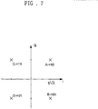
- FIGURE 8 is a negation on the I-part after mapping index #1. Through the negation, the antenna configuration relating to mapping index #17 of Table 3 can be conveyed. Through this mapping, the configuration of 3 SFBC/FSTD is determined.
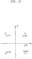
- FIGURE 9 is another example of a negation mapping.
- FIGURE 8 is a negation on the Q-part after mapping index #1. Through the negation, the antenna configuration relating to mapping index #8 of Table 3 can be conveyed. Through this mapping, the configuration of 3 SFBC/FSTD is determined.
- FIGURE 10 is an example of a transport chain 600 illustrating constellation remapping.
- a channel rate coding including rate matching is preformed (Block 601) .
- the channel rate signal is scrambled (Block 602).
- the scrambled signal is modulated (Block 603).
- constellation remapping is performed (Block 604).
- the remapping of the constellation is done so that the resulting mapping will convey the antenna configuration of the base stations 101-103.
- the constellation remapping is performed by first identifying the base stations 101-103 antenna configuration. After the antenna configuration is determined, a mapping that corresponds to the antenna configuration is selected. Using the selected mapping configuration, QPSK remapping is preformed to convey the antenna configuration. Finally, data framing is preformed where data is placed onto frames for transmission (Block 605).
- mapping index #1 in Table 3 is used.
- the overall mapping from the scrambled bits b ⁇ (0),..., b ⁇ ( M bit -1) to the output of the constellation remapping step d ⁇ (0),..., d ⁇ ( M symb -1) can be described as a mapping in Table 3 whose index is a function f ( N ), where N t is the number of transmission antennas in the base stations 101-103.
- the modulation step and constellation remapping step are defined by 3 (out of 24) possible mappings in Table 3.
- mapping index #14 of Table 3 can be viewed by applying a 90 degree shift at the output of the modulation step.
- the 90 degree phase shift simply translates into an I-Q switch with a negation operation.
- a -90 degree shift can be applied at the output of the modulation step on top of mapping #1.
- mapping index #17 of Table 3 can be viewed by applying a negation operation on the I-part at the output of the modulation step.
- mapping index #8 of Table 3 can be viewed by applying a negation operation on the Q-part at the output of the modulation step.
- a mathematical function may be applied to determine the antenna configuration removing the need for Table 3.
- a mod function may be applied to an index that results in the configuration of the antenna.
- the modulo function is applied to the constellation index received by the subscriber station. This removes the need for Table 3, as the modulo result corresponds to the antenna configuration.
- the length-3 mapping sequence m#1,m417,m#8 is repeated.
- d (0) d (0) + d ( M symb -1)
- M symb -1 denotes the real and imaginary parts of d(i)
- FIGURE 11 is a flowchart 700 of the interpretation of signals by a subscriber station received from base stations 101-103.
- a signal is received by the subscriber station (Block 701).
- the subscriber station collects a sequence of symbols over the allocated PBCH resource (Block 702) .
- the constellation is interpreted to determine the proper number of antennas. It is understood that in most cases this will be sufficient to determine the antenna configuration.
- This configuration can be confirmed using the following three assumptions. It is understood that the first assumption chosen will be based upon constellation information, and a second assumption will be used only if the first assumption fails to result in a true CRC check.
- a "true" CRC check refers to a CRC operation where no error appears, and a "false” CRC check refers to a CRC operation where an error appears.
- Blocks 706, 711, and 715 four separate decodes are preformed. These decodes are preformed at the timings 10, 20, 30, and 40 ms. Therefore, while the configuration of the antennas in the base stations 101-103 can be determined, the timing may not be determined. The time is confirmed by testing the decodes at each timing against the CRC check. When the result of the CRC check is true, the timing and antenna configuration is confirmed.
- the number of transmit antennas is known (Block 708). This information along with the correct timing is used to interpret the PBCH content. It is understood that the constellation remapping as a function of number of transmit antennas can be applied to other physical channel, and to other modulations such as BPSK, 16QAM and 64QAM, etc.
- a CRC masking step is added to the PBCH transport block.
- the resulting transmission chain 800 is shown in FIGURE 12 .
- the CRC masking means the CRC bits are masked by a bit sequence that is a function of the number of transmit antennas.
- FIGURE 12 shows that data is input into the system (Block 801).
- a CRC mask is applied to the data entering into the system (Block 802).
- the data is then scrambled (Block 803) and modulated (Block 804). Premapping, as discussed in the previous embodiment, may optionally be added. (Block 805). Finally, the data is placed onto data frames (Block 806).
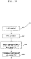
- FIGURE 13 is an example 900 of how the CRC mask may be applied.
- a P-BCH payload is received for transmission (Block 901) .
- a CRC code is generated (Block 902).
- This CRC code is then masked by a sequence that is a function of the number of transmit antennas (Block 903).
- a CRC check is usually performed on data to ensure the reliability and integrity of the data.
- a CRC may be polynomial of x ⁇ 4+x+1. This can be used to check to see that the data is intact. This polynomial can be applied to any data consistent with the CRC-4 standard. Take for instance the following input data: 00000001 (data)
- the data is masked with another CRC mask. Therefore, the data goes through the following transformation: 00000001 (data) ⁇ 00000002 (masked data)
- the present disclosure uses a plurality of masks to alter data. These masks are then checked against the CRC check to determine which is true. For instance, using the data 000000001, the following masks could be used:
- the masked data when received by the subscriber station, goes through an inverse process of demasking. If the masked data is demasked by the "right" mask, then the CRC check will be true. For instance, 00000003 demasked with the one antenna mask would not equal 00000001, and therefore the CRC check would fail. The 00000003 demasked with the two antenna mask would equal 00000001, and therefore the CRC check would succeed. In this way, the data transmitted to a subscriber station can be masked with information relating to the antenna configuration of the base stations 101-103.
- the P-BCH is concatenated with the masked CRC (Block 904).
- the data is combined with the masked CRC allowing the data to be appropriately interpreted by the subscriber station.
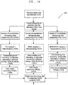
- FIGURE 14 is a flowchart 1000 of the interpretation of signals by a subscriber station received from base stations 101-103.
- a signal is received by the subscriber station (Block 1001).
- the subscriber station collects a sequence of symbols over the allocated PBCH resource (Block 1002) .
- three assumptions are made as to the antenna configuration. One of the three should result in a true result, and the true result will correspond to the correct antenna configuration.
- the CRC embodiment does not give information directly relating to the antenna configuration. Therefore, unlike the QSPK constellation embodiment, each assumption may be tried.
- Blocks 1005, 1011, and 1015 four separate decodes are performed. These decodes are performed at the timings 10, 20, 30, and 40 ms. Therefore, while there are three assumptions being made about the number of antennas in the base stations 101-103, each one of these configurations may have four timings. Therefore, there are actually twelve tests performed to determine the correct configuration of base stations 101-103.
- FIGURE 15 is an example embodiment 1100 where both QPSK constellation mapping and CRC masking are used.
- Data is input into the system (Block 1101) .
- a CRC mask is applied to the data entering into the system (Block 1102) .
- the data is then scrambled (Block 1103) and modulated (Block 1104).
- the antenna configuration is then mapped onto the QPSK constellation, and the data is placed onto data frames (Block 1105) .
- FIGURE 16 is a flowchart 1200 of the interpretation of signals by a subscriber station received from base stations 101-103 using both a QPSK constellation and a CRC mask.
- a signal is received by the subscriber station (Block 1201).
- the subscriber station collects a sequence of symbols over the allocated PBCH resource (Block 1202). This information is used to determine the antenna configuration of the base stations 101-103 through the QPSK constellation. Three assumptions can be used to confirm the antenna configuration obtained from the QPSK constellation.
- Blocks 1205, 1210, and 1214 four separate decodes are performed. These decodes are performed at the timings 10, 20, 30, and 40 ms. Therefore, while there are three assumptions being made about the number of antennas in the base stations 101-103, each one of these configurations may have four timings. Therefore, there are actually twelve tests performed to determine the correct configuration of base stations 101-103.
- the antenna configuration of the base stations 101-103 can be confirmed.
Description
- The present application relates generally to wireless communications and, more specifically, to a technique for improved interference power estimation.
- Modern communication systems include transceivers that comprise a plurality of antennas arranged in a plurality of configurations. In order to convey information using these transceivers, information relating to the configuration of the antennas needs to be communicated to the device communicating with the transceiver. However, this communication requires considerable bandwidth and is not easily done. The conveyance of the configuration of the antennas represents significant overhead to a communication system. Therefore, there is a need in the art for an improved system and method for conveying antenna configuration information.
- In "Discussion on the Improvement of the Blind Detection of the Antenna" (Nortel, 3GPP TSG-RAN 1 Meeting #50-bis, R1-073970, Shanghai, China, October 8th-12th, 2007), approaches to improve the reliability of the blind detection are described. The actual transmitted signal should change when the number of receive antennas change. This change can be accomplished in a way with a change of RE mapping, with the introduction of a scrambling sequence, of modifying the Alamouti mapping format, or of using some type of reliability measure in the decoding of the P-BCH.
- In one embodiment, systems and methods for transmitting data related to the configuration of transmit antennas are disclosed. These methods may include obtaining a data for transmission, encoding the data and modulating the data. During the modulating of the data, the data may be configured in such a way as to convey the configuration of the data through the modulation of the data. These methods may also include obtaining an antenna configuration, obtaining a representation of the antenna configuration, and masking the data with an error correcting code, where the mask corresponds to the antenna configuration.
- In another embodiment, a wireless communication network is disclosed that comprises a plurality of base stations capable of wireless communication with a plurality of subscriber stations within a coverage area of the network. In these embodiments at least one of the plurality of base stations is capable of encoding a transmission antenna configuration into a QPSK constellation and transmitting the QPSK constellation. In addition, the transmission may be masked with an error correction code that corresponds to a transmit antenna configuration.
- In yet another embodiment, systems and methods are disclosed with a base station capable of wireless communication with a plurality of subscriber stations within a coverage area of a network. In these embodiments, the base station is capable of transmitting data with at least one antenna, encoding a configuration of the at least one antenna into a data stream, and transmitting the data stream. These methods may further comprise transmitting an error correction code that has been masked to represent the configuration of the transmit antennas.
- Before undertaking the DETAILED DESCRIPTION OF THE INVENTION below, it may be advantageous to set forth definitions of certain words and phrases used throughout this patent document: the terms "include" and "comprise, " as well as derivatives thereof, mean inclusion without limitation; the term "or," is inclusive, meaning and/or; the phrases "associated with" and "associated therewith," as well as derivatives thereof, may mean to include, be included within, interconnect with, contain, be contained within, connect to or with, couple to or with, be communicable with, cooperate with, interleave, juxtapose, be proximate to, be bound to or with, have, have a property of, or the like; and the term "controller" means any device, system or part thereof that controls at least one operation, such a device may be implemented in hardware, firmware or software, or some combination of at least two of the same. It should be noted that the functionality associated with any particular controller may be centralized or distributed, whether locally or remotely. Definitions for certain words and phrases are provided throughout this patent document, those of ordinary skill in the art should understand that in many, if not most instances, such definitions apply to prior, as well as future uses of such defined words and phrases.
- For a more complete understanding of the present disclosure and its advantages, reference is now made to the following description taken in conjunction with the accompanying drawings, in which like reference numerals represent like parts:
-
FIGURE 1 illustrates an exemplary wireless network that transmits ACK/NACK messages in the uplink according to the principles of the present disclosure; -
FIGURE 2 is a high-level diagram of an OFDMA transmitter according to one embodiment of the present disclosure; -
FIGURE 3 is a high-level diagram of an OFDMA receiver according to one embodiment of the present disclosure; -
FIGURE 4 is a high-level diagram of a transmission chain according to one embodiment of the present disclosure; -
FIGURE 5 is a diagram of a constellation mapping of QPSK modulation according to one embodiment of the present disclosure; -
FIGURE 6 is a diagram of a modified constellation mapping of QPSK modulation according to one embodiment of the present disclosure; -
FIGURE 7 is a diagram of a second modified constellation mapping of QPSK modulation according to one embodiment of the present disclosure; -
FIGURE 8 is a diagram of a third modified constellation mapping of QPSK modulation according to one embodiment of the present disclosure; -
FIGURE 9 is a diagram of a fourth modified constellation mapping of QPSK modulation according to one embodiment of the present disclosure; -
FIGURE 10 is an example of a transport chain illustrating constellation remapping according to one embodiment of the present disclosure; -
FIGURE 11 is a flowchart of the interpretation of signals by a subscriber station according to one embodiment of the present disclosure; -
FIGURE 12 is a block diagram of the mapping of constellations and CRC masking according to one embodiment of the present disclosure; -
FIGURE 13 is a block diagram of CRC masking according to one embodiment of the present disclosure; -
FIGURE 14 is a flowchart of the interpretation of signals by a subscriber station according to one embodiment of the present disclosure; -
FIGURE 15 is a block diagram of the remapping of constellations and CRC mapping according to one embodiment of the present disclosure; and -
FIGURE 16 is a flowchart of the interpretation of signals by a subscriber station using both a QPSK constellation and a CRC mask of the present disclosure. -
FIGURES 1 through 16 , discussed below, and the various embodiments used to describe the principles of the present disclosure in this patent document are by way of illustration only and should not be construed in any way to limit the scope of the disclosure. Those skilled in the art will understand that the principles of the present disclosure may be implemented in any suitably arranged wireless communication system. -
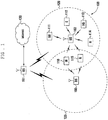
FIGURE 1 illustrates exemplarywireless network 100, which transmits ACK/NACK messages according to the principles of the present disclosure. In the illustrated embodiment,wireless network 100 includes base station (BS) 101, base station (BS) 102, base station (BS) 103, and other similar base stations (not shown).Base station 101 is in communication withbase station 102 andbase station 103.Base station 101 is also in communication with Internet 130 or a similar IP-based network (not shown). -
Base station 102 provides wireless broadband access (via base station 101) to Internet 130 to a first plurality of subscriber stations within coverage area 120 ofbase station 102. The first plurality of subscriber stations includessubscriber station 111, which may be located in a small business (SB),subscriber station 112, which may be located in an enterprise (E),subscriber station 113, which may be located in a WiFi hotspot (HS),subscriber station 114, which may be located in a first residence (R),subscriber station 115, which may be located in a second residence (R), andsubscriber station 116, which may be a mobile device (M), such as a cell phone, a wireless laptop, a wireless PDA, or the like. -
Base station 103 provides wireless broadband access (via base station 101) to Internet 130 to a second plurality of subscriber stations withincoverage area 125 ofbase station 103. The second plurality of subscriber stations includessubscriber station 115 andsubscriber station 116. In an exemplary embodiment, base stations 101-103 may communicate with each other and with subscriber stations 111-116 using OFDM or OFDMA techniques. -
Base station 101 may be in communication with either a greater number or a lesser number of base stations. Furthermore, while only six subscriber stations are depicted inFIGURE 1 , it is understood thatwireless network 100 may provide wireless broadband access to additional subscriber stations. It is noted thatsubscriber station 115 andsubscriber station 116 are located on the edges of both coverage area 120 andcoverage area 125.Subscriber station 115 andsubscriber station 116 each communicate with bothbase station 102 andbase station 103 and may be said to be operating in handoff mode, as known to those of skill in the art. - Subscriber stations 111-116 may access voice, data, video, video conferencing, and/or other broadband services via Internet 130. In an exemplary embodiment, one or more of subscriber stations 111-116 may be associated with an access point (AP) of a WiFi WLAN.
Subscriber station 116 may be any of a number of mobile devices, including a wireless-enabled laptop computer, personal data assistant, notebook, handheld device, or other wireless-enabled device.Subscriber stations -
FIGURE 2 is a high-level diagram of an orthogonal frequency division multiple access (OFDMA) transmit path.FIGURE 3 is a high-level diagram of an orthogonal frequency division multiple access (OFDMA) receive path. InFIGURES 2 and3 , the OFDMA transmit path is implemented in base station (BS) 102 and the OFDMA receive path is implemented in subscriber station (SS) 116 for the purposes of illustration and explanation only. However, it will be understood by those skilled in the art that the OFDMA receive path may also be implemented inBS 102 and the OFDMA transmit path may be implemented inSS 116. - The transmit path in
BS 102 comprises channel coding andmodulation block 205, serial-to-parallel (S-to-P) block 210, Size N Inverse Fast Fourier Transform (IFFT) block 215, parallel-to-serial (P-to-S) block 220, addcyclic prefix block 225, up-converter (UC) 230. The receive path inSS 116 comprises down-converter (DC) 255, removecyclic prefix block 260, serial-to-parallel (S-to-P) block 265, Size N Fast Fourier Transform (FFT) block 270, parallel-to-serial (P-to-S) block 275, channel decoding anddemodulation block 280. - At least some of the components in
FIGURES 2 and3 may be implemented in software while other components may be implemented by configurable hardware or a mixture of software and configurable hardware. In particular, it is noted that the FFT blocks and the IFFT blocks described in this disclosure document may be implemented as configurable software algorithms, where the value of Size N may be modified according to the implementation. - Furthermore, although this disclosure is directed to an embodiment that implements the Fast Fourier Transform and the Inverse Fast Fourier Transform, this is by way of illustration only and should not be construed to limit the scope of the disclosure. It will be appreciated that in an alternate embodiment of the disclosure, the Fast Fourier Transform functions and the Inverse Fast Fourier Transform functions may easily be replaced by Discrete Fourier Transform (DFT) functions and Inverse Discrete Fourier Transform (IDFT) functions, respectively. It will be appreciated that for DFT and IDFT functions, the value of the N variable may be any integer number (i.e., 1, 2, 3, 4, etc.), while for FFT and IFFT functions, the value of the N variable may be any integer number that is a power of two (i.e., 1, 2, 4, 8, 16, etc.).
- In
BS 102, channel coding andmodulation block 205 receives a set of information bits, applies coding (e.g., Turbo coding) and modulates (e.g., QPSK, QAM) the input bits to produce a sequence of frequency-domain modulation symbols. Serial-to-parallel block 210 converts (i.e., de-multiplexes) the serial modulated symbols to parallel data to produce N parallel symbol streams where N is the IFFT/FFT size used inBS 102 andSS 116. Size N IFFT block 215 then performs an IFFT operation on the N parallel symbol streams to produce time-domain output signals. Parallel-to-serial block 220 converts (i.e., multiplexes) the parallel time-domain output symbols from Size N IFFT block 215 to produce a serial time-domain signal. Addcyclic prefix block 225 then inserts a cyclic prefix to the time-domain signal. Finally, up-converter 230 modulates (i.e., up-converts) the output of addcyclic prefix block 225 to RF frequency for transmission via a wireless channel. The signal may also be filtered at baseband before conversion to RF frequency. - The transmitted RF signal arrives at
SS 116 after passing through the wireless channel and reverse operations to those atBS 102 are performed. Down-converter 255 down-converts the received signal to baseband frequency and removecyclic prefix block 260 removes the cyclic prefix to produce the serial time-domain baseband signal. Serial-to-parallel block 265 converts the time-domain baseband signal to parallel time domain signals. Size N FFT block 270 then performs an FFT algorithm to produce N parallel frequency-domain signals. Parallel-to-serial block 275 converts the parallel frequency-domain signals to a sequence of modulated data symbols. Channel decoding anddemodulation block 280 demodulates and then decodes the modulated symbols to recover the original input data stream. - Each of base stations 101-103 may implement a transmit path that is analogous to transmitting in the downlink to subscriber stations 111-116 and may implement a receive path that is analogous to receiving in the uplink from subscriber stations 111-116. Similarly, each one of subscriber stations 111-116 may implement a transmit path corresponding to the architecture for transmitting in the uplink to base stations 101-103 and may implement a receive path corresponding to the architecture for receiving in the downlink from base stations 101-103.
- The present disclosure describes methods and systems to convey information relating to base station configuration to subscriber stations and, more specifically, to relaying base station antenna configuration to subscriber stations. This information can be conveyed through a plurality of methods, including placing antenna configuration into a quadrature-phase shift keying (QPSK) constellation (e.g., n-quadrature amplitude modulation (QAM) signal, wherein n is 2^x) and placing antenna configuration into the error correction data (e.g., cyclic redundancy check (CRC) data). By encoding antenna information into either the QPSK constellation or the error correction data, the base stations 101-103 can convey base stations 101-103 antenna configuration without having to separately transmit antenna configuration. These systems and methods allow for the reduction of overhead while ensuring reliable communication between base stations 101-103 and a plurality of subscriber stations.
- In some embodiments disclosed herein, data is transmitted using QAM. QAM is a modulation scheme which conveys data by modulating the amplitude of two carrier waves. These two waves are referred to as quadrature carriers, and are generally out of phase with each other by 90 degrees. QAM may be represented by a constellation that comprises 2^x points, where x is an integer greater than 1. In the embodiments discussed herein, the constellations discussed will be four point constellations (4-QAM). In a 4-QAM constellation a 2 dimensional graph is represented with one point in each quadrant of the 2 dimensional graph. However, it is explicitly understood that the innovations discussed herein may be used with any modulation scheme with any number of points in the constellation. It is further understood that with constellations with more than four points additional information (e.g., reference power signal) relating to the configuration of the base stations 101-103 may be conveyed consistent with the disclosed systems and methods.
- It is understood that the transmitter within base stations 101-103 performs a plurality of functions prior to actually transmitting data. In the 4-QAM embodiment, QAM modulated symbols are serial-to-parallel converted and input to an inverse fast Fourier transform (IFFT) . At the output of the IFFT, N time-domain samples are obtained. In the disclosed embodiments, N refers to the IFFT/ fast Fourier transform (FFT) size used by the OFDM system. The signal after IFFT is parallel-to-serial converted and a cyclic prefix (CP) is added to the signal sequence. The resulting sequence of samples is referred to as an OFDM symbol.
- At the receiver within the subscriber station, this process is reversed, and the cyclic prefix is first removed. Then the signal is serial-to-parallel converted before being fed into the FFT. The output of the FFT is parallel-to-serial converted, and the resulting QAM modulation symbols are input to the QAM demodulator.
- The total bandwidth in an OFDM system is divided into narrowband frequency units called subcarriers. The number of subcarriers is equal to the FFT/IFFT size N used in the system. In general, the number of subcarriers used for data is less than N because some subcarriers at the edge of the frequency spectrum are reserved as guard subcarriers. In general, no information is transmitted on guard subcarriers.
- In the examples illustrated by
FIGURES 4 ,10 , and12 , the coded BCH transport block is mapped to four subframes (subframes # 0, #1, #2,and #3) within a 40 ms interval. In the embodiment of 4-QAM, the coded broadcast channel (BCH) transport block is mapped to 4 OFDM symbols within a subframe. In case of extended CP, this implies a restriction in the number of idle symbols in the case ofTDD FS type 1 to three idle symbols. - For exemplary purposes, three base stations 101-103 antenna configurations will be used as examples herein. These configurations are one transmission antenna, two transmission antennas using a space frequency block coding (SFBC) transmission scheme, and four transmission antennas using SFBC - frequency switching transmission diversity (FSTD) transmission scheme. While different transmissions schemes are used, detecting the number of transmission antennas based upon the schemes is difficult. Each transmission scheme has a large portion of the signal which can be considered as a subset of the other schemes, and therefore it is difficult to reliably detect and determine the scheme being used based upon the signal. Therefore, the antenna configuration will need to be encoded either into the physical broadcast channel (P-BCH) transport block and related QAM constellation or the error correction data of the P-BCH transport block.
- QPSK modulation is used for P-BCH. As discussed before, the 4-QAM constellation comprises four separate points that are distributed into the four quadrants of a two-dimensional mapping. The following is a table illustrating the constellation mapping that will be discussed in the present disclosure:
Table 1: Constellation Mapping b(i), b(i+1) I Q 00 

01 

10 

11 

- The placing of data into the outgoing transmission of the base stations 101-103 are preformed through a transmission chain. A transmission chain is a series of operations preformed to prepare data for transmission. These operations may include scrambling, modulating, and mapping data. Transmission chains may be used consistent with a plurality of communication techniques, including orthogonal frequency division multiplexing (OFDM).
- In order to facilitate understanding of the numerous embodiments of transmitting base stations 101-103 antenna configuration information, a transmission chain of broadcast channel (BCH) mapped data across a predetermined time interval is illustrated by
FIGURE 4 . It is understood that the examples disclosed relating to the encoding of data disclosed herein range from 10ms-40ms, but that any time interval may be used consistent with the disclosed systems and methods. -
FIGURE 4 is an example of a method that may be used consistent with this disclosure to encode data.FIGURE 4 is a high level description of the transmission of a BCH transport block. The P-BCH is received by the mapping mechanism in a BCH transport block (Block 301). Channel coding which includes rate matching is applied to the BCH transport block(Block 302). As will be discussed herein during channel coding, the data may be modified to embed error correcting information into the data from the BCH transport block that can be used to convey antenna configuration. The encoded and rate matched data is scrambled (Block 303) and modulated (Block 304) . The resulting modulated data is mapped onto the QSPK data stream into frames (Block 305). In some embodiments during the mapping of data the map will be altered to convey antenna configuration information. It is understood that this transmit chain is provided for exemplary purposes only, and that other transmit chains, in various orders with various steps, may be used consistent with the present disclosure. -
FIGURE 5 is a two-dimensional constellation mapping of QPSK modulation using the data shown in Table 1. As was discussed above in each frame encoded by the transmit chain, there are four items that are mapped onto the QSPK data stream. For example purposes, these four information elements will be referred to as 00 (in quadrant A), 01 (in quadrant B), 10 (in quadrant C), and 11 (in quadrant D). It is understood that the QPSK constellation mapping can provide information relating to the configuration of the antennas within the base stations 101-103. In general, since there are 4 constellation points in a QPSK modulation, there are a total of 4! (24) total possible mappings as shown in below. The following is a table of all of the available mappings:TABLE 2: QPSK Mappings mapping index # 00 01 10 11 1 A B C D 2 A B D C 3 A C B D 4 A C D B 5 A D B C 6 A D C B 7 B A C D 8 B A D C 9 B C A D 10 B C D A 11 B D A C 12 B D C A 13 C A B D 14 C A D B 15 C B A D 16 C B D A 17 C D A B 18 C D B A 19 D A B C 20 D A C B 21 D B A C 22 D B C A 23 D C A B 24 D C B A -
FIGURE 5 is an example of mapping index #14 shown in Table 2. In his mapping, A, B, C, and D are quadrants of the QPSK constellation. The mapping ofelements TABLE 3: QPSK Mappings with Antenna Configuration mapping index # 00 01 10 11 Configuration 1 A B C D 1 2 A B D C 1 3 A C B D 1 4 A C D B 2 SFBC 5 A D B C 2 SFBC 6 A D C B 2 SFBC 7. B A C D 2 SFBC 8 B A D C 4 SFBC/FSTD 9 B C A D 3 SFBC/FSTD 10 B C D A 3 SFBC/FSTD 11 B D A C 4 SFBC/FSTD 12 B D C A 3 SFBC/FSTD 13 C A B D 3 SFBC/FSTD 14 C A D B 2 SFBC 15 C B A D 3 SFBC/FSTD 16 C B D A 3 SFBC/FSTD 17 C D A B 2 SFBC 18 C D B A 3 SFBC/FSTD 19 D A B C 3 SFBC/FSTD 20 D A C B 3 SFBC/FSTD 21 D B A C 3 SFBC/FSTD 22 D B C A 3 SFBC/FSTD 23 D C A B 3 SFBC/FSTD 24 D C B A 3 SFBC/FSTD - Using Table 3, the antenna configuration of the base stations 101-103 transmitting the constellation illustrated by
FIGURE 5 can be determined. The antenna configuration can be determined through the QPSK mapping and is independent of the transmission scheme and the number of antennas used. Therefore, the use of a constellation mapping coupled with a known QPSK table, such as the one illustrated by Table 3, offers a reliable method for determining the antenna configuration of the base stations 101-103. -
FIGURE 5 is one example of a QPSK mapping, andFIGURE 6 ,7 ,8 , and9 are examples of various other mappings.FIGURE 6 is an example ofmapping # 1 in Table 2, and is substantially similar toFIGURE 5 with the addition of illustrating the position of each mapping relative to 1/√2. -
FIGURES 7 ,8 , and9 are examples of mappings that are preformed uponFIGURE 6 . The purpose of these mappings is to add antenna configuration data to the QPSK mapping of data. This addition of data may be preformed through mapping, shifting, or negation as illustrated byFIGURES 7 ,8 , and9 . It is explicitly understood that any method of adjusting the QPSK constellation may be used. -
FIGURE 7 is a 90 degree phase shift of the data inFIGURE 6 . Through the phase shift ofFIGURE 6 , the antenna configuration relating tomapping index # 11 of Table 3 can be conveyed. Through this mapping, the configuration of 4 SFBC/FSTD is determined. -
FIGURE 8 is an example of a negation mapping.FIGURE 8 is a negation on the I-part after mappingindex # 1. Through the negation, the antenna configuration relating to mapping index #17 of Table 3 can be conveyed. Through this mapping, the configuration of 3 SFBC/FSTD is determined. -
FIGURE 9 is another example of a negation mapping.FIGURE 8 is a negation on the Q-part after mappingindex # 1. Through the negation, the antenna configuration relating to mapping index #8 of Table 3 can be conveyed. Through this mapping, the configuration of 3 SFBC/FSTD is determined. -
FIGURE 10 is an example of atransport chain 600 illustrating constellation remapping. In the embodiment shown inFIGURE 10 , a channel rate coding including rate matching is preformed (Block 601) . In addition, the channel rate signal is scrambled (Block 602). Next, the scrambled signal is modulated (Block 603). After the signal has been modulated, constellation remapping is performed (Block 604). The remapping of the constellation is done so that the resulting mapping will convey the antenna configuration of the base stations 101-103. The constellation remapping is performed by first identifying the base stations 101-103 antenna configuration. After the antenna configuration is determined, a mapping that corresponds to the antenna configuration is selected. Using the selected mapping configuration, QPSK remapping is preformed to convey the antenna configuration. Finally, data framing is preformed where data is placed onto frames for transmission (Block 605). - It is understood that in the modulation step (Block 603),
mapping index # 1 in Table 3 is used. After the constellation remapping step, the overall mapping from the scrambled bits b̃(0),...,b̃(M bit-1) to the output of the constellation remapping step d̃(0),...,d̃(M symb-1) can be described as a mapping in Table 3 whose index is a function f(N), where Nt is the number of transmission antennas in the base stations 101-103. - In case when there are 3 possible antenna configurations with 1, 2, or 4 transmit antennas, the modulation step and constellation remapping step are defined by 3 (out of 24) possible mappings in Table 3. For example, the following function shows the mapping that corresponds to the number of antennas in a given configuration:

- Note that the
notation m# 1 is used to denote the first mapping in Table 3. The remapping (Block 604) will depend upon the antenna configuration. For the single transmit antenna configuration case, the constellation remapping step is simply d̃(i) = d̃(i) for i=0, M symb-1. - In the case where there are two transmit antennas, as shown in
FIGURE 5 , the mapping index #14 of Table 3 can be viewed by applying a 90 degree shift at the output of the modulation step. For the sequence at the output of the modulation step, d(0),...,d(M symb-1), d(i) = dI (i) +jdQ (i) for i=0,... M Symb-1, and are real and imaginary parts of d(i). Then the output of the constellation remapping step gives a symbol sequence described by:
- As shown in this equation, the 90 degree phase shift simply translates into an I-Q switch with a negation operation.
- In the case that there are four transmit antennas, a -90 degree shift can be applied at the output of the modulation step on top of
mapping # 1. For the sequence at the output of the modulation step d(0),...,d(M symb-1), if we denote d(i) = dI (i) + jdQ (i) for i=0,...M symb-1, and dI (i),dQ (i) are denoted as the real and imaginary parts of d(i), then the output of the constellation remapping step gives a symbol sequence described by d̃(i)=-j·d(i)=-jdI (i)+dg (i) for i=0,...M symb-1. This -90 degree phase shift also translates into an I-Q switch with a negation operation. - For another example of this embodiment, the following function in the constellation remapping is described:

- As discussed above for a single transmit antenna the constellation remapping is d̃(i) = d(i) for i=0,... M symb-1.
- Where there are two transmit antennas the mapping index #17 of Table 3 can be viewed by applying a negation operation on the I-part at the output of the modulation step. For the sequence at the output of the modulation step d(0),...,d(M symb-1), if d(i) = dI (i) + jdQ (i) for i=0, ... Msymb-1, are denoted as the real and imaginary parts of d(i), then the output of the constellation remapping step gives a symbol sequence described by d(i)=-dj (i)+jdQ (i) for i=0,... M symb-1.
- Where there are three transmit antennas, the mapping index #8 of Table 3 can be viewed by applying a negation operation on the Q-part at the output of the modulation step. For the sequence at the output of the modulation step d(0),...,d(M symb-1), if d(i) = dI (i) + jdQ (i) for i=0,... M symb-1, and dI (i),dQ (i) denote the real and imaginary parts of d(i), then the output of the constellation remapping step gives a symbol sequence described by d̃(i) = dj (i) - jdQ (i) for i=0,... M symb-1.
- In another embodiment, a mathematical function may be applied to determine the antenna configuration removing the need for Table 3. In this embodiment, a mod function may be applied to an index that results in the configuration of the antenna. In this example embodiment, the index of the mapping is applied to a modulo function which results in an integer that corresponds with an antenna configuration. For example, for the function g(Nl ,i) as (for i=0,... M symb-1), the following relationships between antenna configuration and mapping sequences can be determined:

- The modulo function is applied to the constellation index received by the subscriber station. This removes the need for Table 3, as the modulo result corresponds to the antenna configuration.
- For the single antenna configuration, the modulo constellation remapping is simply d̃(i) = d(i) for i=0,... M symb-1.
- For the two transmit antenna modulo configuration, the length-3 mapping
sequence m# 1,m417,m#8 is repeated. For the sequence at the output of the modulation step d(0),...,d(M symb-1), if d(i) = dI (i) + jdQ (i) for i=0,... Msymb-1 denotes the real and imaginary parts of d(i), then the output of the constellation remapping step gives a symbol sequence described by:
- For the four transmit antenna modulo configuration, output of the constellation remapping step gives a symbol sequence described by:

-
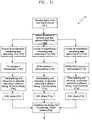
FIGURE 11 is aflowchart 700 of the interpretation of signals by a subscriber station received from base stations 101-103. In this flowchart, a signal is received by the subscriber station (Block 701). The subscriber station then collects a sequence of symbols over the allocated PBCH resource (Block 702) . At this point, the constellation is interpreted to determine the proper number of antennas. It is understood that in most cases this will be sufficient to determine the antenna configuration. This configuration can be confirmed using the following three assumptions. It is understood that the first assumption chosen will be based upon constellation information, and a second assumption will be used only if the first assumption fails to result in a true CRC check. A "true" CRC check refers to a CRC operation where no error appears, and a "false" CRC check refers to a CRC operation where an error appears. - In the first assumption, there is an inverse constellation remapping step assuming a 1 transit antenna configuration (Block 703). The output from the remapping step is then demodulated assuming a single transmitter (Block 704). Next, descrambling and decoding are performed on the data (Block 705). Finally, a CRC check is performed on the decoded data. (Block 707). If the CRC check passes, and the data is not corrupt, then the assumption that there is one transmit antenna is confirmed.
- In the second assumption, there is an inverse constellation remapping step assuming a two transit antenna configuration (Block 709). The output from the remapping step is then demodulated assuming two transmitters using an SFBC receiver (Block 710). Next, descrambling and decoding are performed on the data (Block 711). Finally, a CRC check is performed on the decoded data (Block 712). If the CRC check passes, and the data is not corrupt, then the assumption that there are two transmit antennas is confirmed.
- In a third assumption, there is an inverse constellation remapping step assuming a four transit antenna configuration (Block 713). The output from the remapping step is then demodulated assuming four transmitters using an SFBC/FSTD receiver (Block 714). Next, descrambling and decoding are performed on the data (Block 715). Finally, a CRC check is performed on the decoded data (Block 716). If the CRC check passes, and the data is not corrupt, then the assumption that there are four transmit antennas is confirmed.
- In each of Blocks 706, 711, and 715 four separate decodes are preformed. These decodes are preformed at the
timings 10, 20, 30, and 40 ms. Therefore, while the configuration of the antennas in the base stations 101-103 can be determined, the timing may not be determined. The time is confirmed by testing the decodes at each timing against the CRC check. When the result of the CRC check is true, the timing and antenna configuration is confirmed. - After one of the assumptions is confirmed, the number of transmit antennas is known (Block 708). This information along with the correct timing is used to interpret the PBCH content. It is understood that the constellation remapping as a function of number of transmit antennas can be applied to other physical channel, and to other modulations such as BPSK, 16QAM and 64QAM, etc.
- In another embodiment of the present disclosure, a CRC masking step is added to the PBCH transport block. The resulting
transmission chain 800 is shown inFIGURE 12 . The CRC masking means the CRC bits are masked by a bit sequence that is a function of the number of transmit antennas. -
FIGURE 12 shows that data is input into the system (Block 801). A CRC mask is applied to the data entering into the system (Block 802). The data is then scrambled (Block 803) and modulated (Block 804). Premapping, as discussed in the previous embodiment, may optionally be added. (Block 805). Finally, the data is placed onto data frames (Block 806). -
FIGURE 13 is an example 900 of how the CRC mask may be applied. A P-BCH payload is received for transmission (Block 901) . Based on the data, a CRC code is generated (Block 902). This CRC code is then masked by a sequence that is a function of the number of transmit antennas (Block 903). - A CRC check is usually performed on data to ensure the reliability and integrity of the data. There are many ways of calculating a CRC code and implementing a CRC check. For example, a CRC may be polynomial of x^4+x+1. This can be used to check to see that the data is intact. This polynomial can be applied to any data consistent with the CRC-4 standard. Take for instance the following input data:
00000001 (data) - If sent and received over a known communications channel, and this data remains intact. The following function illustrates that the CRC of this data would return a true result.
CRC(000000001) = true - However, with the present invention, the data is masked with another CRC mask. Therefore, the data goes through the following transformation:
00000001 (data) → 00000002 (masked data) - Using the old CRC check, the result would be false.
CRC(000000002) = False - The present disclosure uses a plurality of masks to alter data. These masks are then checked against the CRC check to determine which is true. For instance, using the data 000000001, the following masks could be used:
- 00000001 (data) → 00000002 (masked data, one antenna)
- 00000001 (data) → 00000003 (masked data, two antennas)
- 00000001 (data) → 00000004 (masked data, four antennas)
- The masked data, when received by the subscriber station, goes through an inverse process of demasking. If the masked data is demasked by the "right" mask, then the CRC check will be true. For instance, 00000003 demasked with the one antenna mask would not equal 00000001, and therefore the CRC check would fail. The 00000003 demasked with the two antenna mask would equal 00000001, and therefore the CRC check would succeed. In this way, the data transmitted to a subscriber station can be masked with information relating to the antenna configuration of the base stations 101-103.
- Returning to
FIGURE 13 , the P-BCH is concatenated with the masked CRC (Block 904). In this block, the data is combined with the masked CRC allowing the data to be appropriately interpreted by the subscriber station. -
FIGURE 14 is aflowchart 1000 of the interpretation of signals by a subscriber station received from base stations 101-103. In this flowchart, a signal is received by the subscriber station (Block 1001). The subscriber station then collects a sequence of symbols over the allocated PBCH resource (Block 1002) . At this point, three assumptions are made as to the antenna configuration. One of the three should result in a true result, and the true result will correspond to the correct antenna configuration. Unlike the embodiment that encodes the antenna configuration into the QSPK constellation, the CRC embodiment does not give information directly relating to the antenna configuration. Therefore, unlike the QSPK constellation embodiment, each assumption may be tried. - In a first assumption, there an inverse constellation remapping step assuming a 1 transit antenna configuration (Block 1003). The output from the remapping step is then demodulated assuming a single transmitter (Block 1004). Next, descrambling and decoding are performed on the data (Block 1005). Finally, a CRC check is performed on the decoded data using a first CRC mask. (Block 1006). If the CRC check passes, then the assumption that there is one transmit antenna is confirmed.
- In a second assumption, there is an inverse constellation remapping step assuming a two transit antenna configuration (Block 1009) . The output from the remapping step is then demodulated assuming two transmitters using an SFBC receiver (Block 1010). Next, descrambling and decoding are performed on the data (Block 1011). Finally, a CRC check is performed on the decoded data using a second CRC mask (Block 1012) . If the CRC check passes, then the assumption that there are two transmit antennas is confirmed.
- In a third assumption, there is an inverse constellation remapping step assuming a four transit antenna configuration (Block 1013). The output from the remapping step is then demodulated assuming four transmitters using an SFBC/FSTD receiver (Block 1014) . Next, descrambling and decoding are performed on the data (Block 1015). Finally, a CRC check is performed on the decoded data using a third CRC mask (Block 1016). If the CRC check passes, then the assumption that there are four transmit antennas is confirmed.
- In each of Blocks 1005, 1011, and 1015, four separate decodes are performed. These decodes are performed at the
timings 10, 20, 30, and 40 ms. Therefore, while there are three assumptions being made about the number of antennas in the base stations 101-103, each one of these configurations may have four timings. Therefore, there are actually twelve tests performed to determine the correct configuration of base stations 101-103. - After one of the assumptions is confirmed, the number of transmit antennas is known. This information along with the correct timing is used to interpret the PBCH content (Block 1007).
- It is understood that both the QPSK constellation and error correcting codes may be used in a single embodiment.
FIGURE 15 is anexample embodiment 1100 where both QPSK constellation mapping and CRC masking are used. Data is input into the system (Block 1101) . A CRC mask is applied to the data entering into the system (Block 1102) . The data is then scrambled (Block 1103) and modulated (Block 1104). The antenna configuration is then mapped onto the QPSK constellation, and the data is placed onto data frames (Block 1105) . -
FIGURE 16 is aflowchart 1200 of the interpretation of signals by a subscriber station received from base stations 101-103 using both a QPSK constellation and a CRC mask. In this flowchart, a signal is received by the subscriber station (Block 1201). The subscriber station then collects a sequence of symbols over the allocated PBCH resource (Block 1202). This information is used to determine the antenna configuration of the base stations 101-103 through the QPSK constellation. Three assumptions can be used to confirm the antenna configuration obtained from the QPSK constellation. - In a first assumption, there is an inverse constellation remapping step assuming a 1 transit antenna configuration (Block 1203) . The output from the remapping step is then demodulated assuming a single transmitter (Block 1204). Next, descrambling and decoding are performed on the data (Block 1205). Finally, a CRC check is performed on the decoded data using a first CRC mask (Block 1206). If the CRC check passes, then the assumption that there is one transmit antenna is confirmed.
- In a second assumption, there is an inverse constellation remapping step assuming a two transit antenna configuration (Block 1208) . The output from the remapping step is then demodulated assuming two transmitters using an SFBC receiver (Block 1209) . Next, descrambling and decoding are performed on the data (Block 1210). Finally, a CRC check is performed on the decoded data using a second CRC mask (Block 1211) . If the CRC check passes, then the assumption that there are two transmit antennas is confirmed.
- In a third assumption, there is an inverse constellation remapping step assuming a four transit antenna configuration (Block 1212). The output from the remapping step is then demodulated assuming four transmitters using an SFBC/FSTD receiver (Block 1213). Next, descrambling and decoding are performed on the data (Block 1214) . Finally, a CRC check is performed on the decoded data using a third CRC mask (Block 1215). If the CRC check passes, then the assumption that there are four transmit antennas is confirmed.
- In each of Blocks 1205, 1210, and 1214, four separate decodes are performed. These decodes are performed at the
timings 10, 20, 30, and 40 ms. Therefore, while there are three assumptions being made about the number of antennas in the base stations 101-103, each one of these configurations may have four timings. Therefore, there are actually twelve tests performed to determine the correct configuration of base stations 101-103. - After one of the assumptions is confirmed, the number of transmit antennas is known. This information along with the correct timing is used to interpret the PBCH content (Block 1207).
- Through the use of both QPSK constellations and CRC masks, the antenna configuration of the base stations 101-103 can be confirmed.
- Although the present disclosure has been described with an exemplary embodiment, various changes and modifications may be suggested to one skilled in the art. It is intended that the present disclosure encompass such changes and modifications as fall within the scope of the appended claims.
Claims (12)
- A method by a terminal (116) in a wireless communication system, comprising:receiving (1001), on a physical broadcast channel, PBCH, signals including a data and masked cyclic redundancy check, CRC, from a base station (101 - 103);demodulating (1004) the signals based on a transmission scheme corresponding to a single transmitter by assuming that a number of transmit antennas is 1;descrambling and decoding (1005) the demodulated signals at four different transmission timings;performing (1006) a CRC check for the masked CRC using a first masking sequence corresponding to the number of transmit antennas being 1 among a plurality of masking sequences, wherein each of the plurality of masking sequence is corresponding to a number of transmit antennas ; anddetermining that the number of transmit antennas configured in the base station is 1, if the CRC check using the first masking sequence is passed.
- The method of claim 1, further comprising:demodulating (1010) the signals based on a transmission scheme corresponding to two transmitters by assuming that a number of transmit antennas is 2;descrambling and decoding (1011) the demodulated signals at four different transmission timings;performing (1012) a CRC check for the masked CRC using a second masking sequence corresponding to the number of transmit antennas being 2 among the plurality of masking sequences ; anddetermining that the number of transmit antennas configured in the base station is 2, if the CRC check using the second masking sequence is passed.
- The method of claim 2, further comprising:demodulating (1014) the signals based on a transmission scheme corresponding to four transmitters by assuming that a number of transmit antennas is 4;descrambling and decoding (1015) the demodulated signals at four different transmission timings;performing (1016) a CRC check for the masked CRC using a third masking sequence corresponding to the number of transmit antennas being 4 among the plurality of masking sequences ; anddetermining that the number of transmit antennas configured in the base station is 4, if the CRC check using the third masking sequence is passed.
- The method of claim 2, wherein the transmission scheme corresponding to the two transmitters is a space-frequency block code, SFBC, scheme.
- The method of claim 3, wherein the transmission scheme corresponding to the four transmitters is a SFBC - frequency switching transmission diversity, SFBC-FSTD, scheme.
- The method of claim 1, wherein a modulation scheme of the PBCH is based on a quadrature phase shift keying, QPSK.
- A terminal (116) in a wireless communication system, comprising:a receiver configured to receive, on a physical broadcast channel (PBCH), signals including a data and masked CRC from a base station; anda processor configured to demodulate the signals based on a transmission scheme corresponding to a single transmitter by assuming that a number of transmit antennas is 1, to descramble and decode the demodulated signals at four different transmission timings, to perform a CRC check for the masked CRC using a first masking sequence corresponding to the number of transmit antennas being 1 among a plurality of masking sequences, wherein each of the plurality of masking sequence is corresponding to a number of transmit antennas, and to determine that the number of transmit antennas configured in the base station is 1, if the CRC check using the first masking sequence is passed.
- The terminal of claim 7, wherein the processor is further configured to demodulate the signals based on a transmission scheme corresponding to two transmitters by assuming that a number of transmit antennas is 2, to descramble and decode the demodulated signals at four different transmission timings, to perform a CRC check for the masked CRC using a second masking sequence corresponding to the number of transmit antennas being 2 among the plurality of masking sequences, and to determine that the number of transmit antennas configured in the base station is 2, if the CRC check using the second masking sequence is passed.
- The terminal of claim 8, wherein the processor is further configured to demodulate the signals based on a transmission scheme corresponding to four transmitters by assuming that a number of transmit antennas is 4, to descramble and decode the demodulated signals at four different transmission timings, to perform a CRC check for the masked CRC using a third masking sequence corresponding to the number of transmit antennas being 4 among the plurality of masking sequences, and to determine that the number of transmit antennas configured in the base station is 4, if the CRC check using the third masking sequence is passed.
- The terminal of claim 8, wherein the transmission scheme corresponding to the two transmitters is a space-frequency block code, SFBC, scheme.
- The terminal d of claim 9, wherein the transmission scheme corresponding to the four transmitters is a SFBC - frequency switching transmission diversity, SFBC-FSTD, scheme.
- The terminal of claim 7, wherein a modulation scheme of the PBCH is based on a quadrature phase shift keying, QPSK.
Applications Claiming Priority (5)
| Application Number | Priority Date | Filing Date | Title |
|---|---|---|---|
| US99685707P | 2007-12-07 | 2007-12-07 | |
| US12/291,274 US8538335B2 (en) | 2007-12-07 | 2008-11-07 | Physical broadcast channel (PBCH) transmission for reliable detection of antenna configuration |
| PCT/KR2008/007108 WO2009072789A2 (en) | 2007-12-07 | 2008-12-02 | Physical broadcast channel (pbch) transmission for reliable detection of antenna configuration |
| EP08857924.8A EP2218229B1 (en) | 2007-12-07 | 2008-12-02 | Physical broadcast channel (pbch) transmission for reliable detection of antenna configuration |
| EP17199186.2A EP3301877B1 (en) | 2007-12-07 | 2008-12-02 | Physical broadcast channel (pbch) transmission for reliable detection of antenna configuration |
Related Parent Applications (2)
| Application Number | Title | Priority Date | Filing Date |
|---|---|---|---|
| EP17199186.2A Division EP3301877B1 (en) | 2007-12-07 | 2008-12-02 | Physical broadcast channel (pbch) transmission for reliable detection of antenna configuration |
| EP08857924.8A Division EP2218229B1 (en) | 2007-12-07 | 2008-12-02 | Physical broadcast channel (pbch) transmission for reliable detection of antenna configuration |
Publications (2)
| Publication Number | Publication Date |
|---|---|
| EP3554029A1 EP3554029A1 (en) | 2019-10-16 |
| EP3554029B1 true EP3554029B1 (en) | 2020-10-14 |
Family
ID=40718339
Family Applications (3)
| Application Number | Title | Priority Date | Filing Date |
|---|---|---|---|
| EP08857924.8A Active EP2218229B1 (en) | 2007-12-07 | 2008-12-02 | Physical broadcast channel (pbch) transmission for reliable detection of antenna configuration |
| EP17199186.2A Active EP3301877B1 (en) | 2007-12-07 | 2008-12-02 | Physical broadcast channel (pbch) transmission for reliable detection of antenna configuration |
| EP19175569.3A Active EP3554029B1 (en) | 2007-12-07 | 2008-12-02 | Physical broadcast channel (pbch) transmission for reliable detection of antenna configuration |
Family Applications Before (2)
| Application Number | Title | Priority Date | Filing Date |
|---|---|---|---|
| EP08857924.8A Active EP2218229B1 (en) | 2007-12-07 | 2008-12-02 | Physical broadcast channel (pbch) transmission for reliable detection of antenna configuration |
| EP17199186.2A Active EP3301877B1 (en) | 2007-12-07 | 2008-12-02 | Physical broadcast channel (pbch) transmission for reliable detection of antenna configuration |
Country Status (17)
| Country | Link |
|---|---|
| US (3) | US8538335B2 (en) |
| EP (3) | EP2218229B1 (en) |
| JP (3) | JP5341910B2 (en) |
| KR (1) | KR101613872B1 (en) |
| CN (2) | CN103647745B (en) |
| AU (1) | AU2008332137B2 (en) |
| BR (1) | BRPI0820459B1 (en) |
| CA (1) | CA2706908C (en) |
| ES (2) | ES2648983T3 (en) |
| HU (2) | HUE044760T2 (en) |
| MX (1) | MX2010005766A (en) |
| MY (1) | MY156067A (en) |
| PT (2) | PT3301877T (en) |
| RU (2) | RU2621004C2 (en) |
| TR (1) | TR201908997T4 (en) |
| WO (1) | WO2009072789A2 (en) |
| ZA (1) | ZA201003421B (en) |
Families Citing this family (18)
| Publication number | Priority date | Publication date | Assignee | Title |
|---|---|---|---|---|
| EP1811674A1 (en) * | 2006-01-23 | 2007-07-25 | Motorola, Inc. | Apparatus and methods for jointly decoding messages based on apriori knowledge of modified codeword transmission |
| US8279846B2 (en) * | 2007-05-10 | 2012-10-02 | Telefonaktiebolaget Lm Ericsson (Publ) | Broadcast channel timing detection |
| US8189581B2 (en) * | 2007-06-20 | 2012-05-29 | Motorola Mobility, Inc. | Method, signal and apparatus for managing the transmission and receipt of broadcast channel information |
| US8290088B2 (en) | 2007-08-07 | 2012-10-16 | Research In Motion Limited | Detecting the number of transmit antennas in a base station |
| US7899051B2 (en) * | 2007-12-31 | 2011-03-01 | Motorola Mobility, Inc. | Broadcast channel signal, apparatus and method for transmitting and decoding broadcast channel information |
| US8135359B2 (en) * | 2008-01-04 | 2012-03-13 | Nokia Corporation | Method and apparatus for conveying antenna configuration information |
| CN105515631B (en) * | 2008-02-04 | 2019-05-07 | 诺基亚公司 | Method and apparatus for transmitting antenna configuration information via shielding |
| US8458558B2 (en) | 2008-04-30 | 2013-06-04 | Motorola Mobility Llc | Multi-antenna configuration signaling in wireless communication system |
| US8144712B2 (en) | 2008-08-07 | 2012-03-27 | Motorola Mobility, Inc. | Scheduling grant information signaling in wireless communication system |
| JP5801721B2 (en) * | 2009-01-26 | 2015-10-28 | ドレクセル ユニバーシティ | System and method for selecting a reconfigurable antenna in a MIMO system |
| CN102158446B (en) * | 2010-02-11 | 2014-03-19 | 中兴通讯股份有限公司 | Method and device for decoding physical broadcast channel (PBCH) in time division duplex (TDD) system |
| US8942308B2 (en) * | 2011-07-25 | 2015-01-27 | Blackberry Limited | Multi-level coding and iterative decoding using sparse space codes |
| US9559810B2 (en) * | 2012-09-10 | 2017-01-31 | Intel Corporation | Methods and arrangements for a check sequence |
| US8913965B2 (en) * | 2012-11-19 | 2014-12-16 | Ixia | Methods, systems, and computer readable media for detecting antenna port misconfigurations |
| KR20140080296A (en) * | 2012-12-20 | 2014-06-30 | 주식회사 팬택 | User Equipment, Information Receiving Method Thereof, Base Station, and Information Transmitting Method Thereof |
| CN104144030B (en) * | 2013-05-09 | 2019-05-10 | 中兴通讯股份有限公司 | Data sending, receiving method, data are sent and receiving end |
| CN108933641B (en) | 2017-05-22 | 2022-10-11 | 中兴通讯股份有限公司 | Data sending and processing method and device, network side equipment and terminal |
| CN111213330B (en) * | 2017-07-27 | 2022-03-08 | 苹果公司 | Scrambling of Physical Broadcast Channel (PBCH) |
Family Cites Families (25)
| Publication number | Priority date | Publication date | Assignee | Title |
|---|---|---|---|---|
| US6038263A (en) | 1997-07-31 | 2000-03-14 | Motorola, Inc. | Method and apparatus for transmitting signals in a communication system |
| JP2001111614A (en) * | 1999-10-06 | 2001-04-20 | Sony Corp | Communication method, communication system, transmitter, receiver and communication unit |
| US6477210B2 (en) | 2000-02-07 | 2002-11-05 | At&T Corp. | System for near optimal joint channel estimation and data detection for COFDM systems |
| KR100493068B1 (en) * | 2000-03-08 | 2005-06-02 | 삼성전자주식회사 | Method and apparatus for semi-blind transmit antenna array using feedback information in mobile communication system |
| US6934317B1 (en) * | 2000-10-11 | 2005-08-23 | Ericsson Inc. | Systems and methods for communicating spread spectrum signals using variable signal constellations |
| CA2504687C (en) | 2002-11-04 | 2008-08-12 | Research In Motion Limited | Method and apparatus for regulating the transmitted power in multi-rate wireless communication systems |
| CN100472998C (en) | 2003-02-13 | 2009-03-25 | 株式会社Ntt都科摩 | Differential multiple-length transmit and reception diversity |
| KR101000388B1 (en) * | 2003-05-15 | 2010-12-13 | 엘지전자 주식회사 | mobile communication system, and signaling method of the same |
| US7773694B2 (en) | 2003-07-02 | 2010-08-10 | Panasonic Corporation | Communication apparatus and communication method |
| US7200405B2 (en) * | 2003-11-18 | 2007-04-03 | Interdigital Technology Corporation | Method and system for providing channel assignment information used to support uplink and downlink channels |
| JP4256301B2 (en) * | 2004-05-28 | 2009-04-22 | 株式会社東芝 | Wireless communication device |
| US8144800B2 (en) * | 2004-09-18 | 2012-03-27 | Broadcom Corporatino | Downstream transmitter and cable modem receiver for 1024 QAM |
| JP4308817B2 (en) * | 2004-12-01 | 2009-08-05 | 三星電子株式会社 | Highly reliable data transmission / reception method and apparatus in a mobile communication system supporting packet data transmission |
| JP4633542B2 (en) * | 2005-05-26 | 2011-02-16 | パナソニック株式会社 | Base station apparatus, mobile station apparatus, and radio transmission method |
| US8068872B2 (en) * | 2005-10-06 | 2011-11-29 | Telefonaktiebolaget Lm Ericsson (Publ) | Signaling support for antenna selection using subset lists and subset masks |
| EP1982451A4 (en) | 2006-01-13 | 2010-12-29 | Lg Electronics Inc | A method and apparatus for achieving transmit diversity and spatial multiplexing using antenna selection based on feedback information |
| WO2007102344A1 (en) | 2006-02-28 | 2007-09-13 | Matsushita Electric Industrial Co., Ltd. | Radio communication device and relay transmission method |
| CN1829138B (en) | 2006-04-07 | 2010-04-07 | 清华大学 | Self-adaptive MIMO transmit-receive system and its method |
| MY187397A (en) | 2006-04-28 | 2021-09-22 | Qualcomm Inc | Method and apparatus for enhanced paging |
| US8290088B2 (en) * | 2007-08-07 | 2012-10-16 | Research In Motion Limited | Detecting the number of transmit antennas in a base station |
| US8135359B2 (en) * | 2008-01-04 | 2012-03-13 | Nokia Corporation | Method and apparatus for conveying antenna configuration information |
| CN105515631B (en) * | 2008-02-04 | 2019-05-07 | 诺基亚公司 | Method and apparatus for transmitting antenna configuration information via shielding |
| AU2010207287B2 (en) * | 2009-01-26 | 2014-10-23 | Sharp Kabushiki Kaisha | Radio communication system, base station apparatus, mobile station apparatus and radio communication method |
| KR101639407B1 (en) * | 2009-07-30 | 2016-07-13 | 엘지전자 주식회사 | Apparatus and method for transmitting channel state information in a mobile communication system |
| JP4862086B2 (en) * | 2010-03-04 | 2012-01-25 | シャープ株式会社 | Wireless communication system, base station apparatus, mobile station apparatus, wireless communication method, and integrated circuit |
-
2008
- 2008-11-07 US US12/291,274 patent/US8538335B2/en active Active
- 2008-12-02 CN CN201310726247.7A patent/CN103647745B/en active Active
- 2008-12-02 CN CN200880126492.1A patent/CN101939959B/en active Active
- 2008-12-02 EP EP08857924.8A patent/EP2218229B1/en active Active
- 2008-12-02 CA CA2706908A patent/CA2706908C/en active Active
- 2008-12-02 AU AU2008332137A patent/AU2008332137B2/en active Active
- 2008-12-02 TR TR2019/08997T patent/TR201908997T4/en unknown
- 2008-12-02 ES ES08857924.8T patent/ES2648983T3/en active Active
- 2008-12-02 KR KR1020107012336A patent/KR101613872B1/en active IP Right Grant
- 2008-12-02 MY MYPI2010002462A patent/MY156067A/en unknown
- 2008-12-02 BR BRPI0820459-4A patent/BRPI0820459B1/en active IP Right Grant
- 2008-12-02 ES ES17199186T patent/ES2731840T3/en active Active
- 2008-12-02 PT PT17199186T patent/PT3301877T/en unknown
- 2008-12-02 WO PCT/KR2008/007108 patent/WO2009072789A2/en active Application Filing
- 2008-12-02 HU HUE17199186 patent/HUE044760T2/en unknown
- 2008-12-02 HU HUE08857924A patent/HUE035505T2/en unknown
- 2008-12-02 MX MX2010005766A patent/MX2010005766A/en active IP Right Grant
- 2008-12-02 PT PT88579248T patent/PT2218229T/en unknown
- 2008-12-02 EP EP17199186.2A patent/EP3301877B1/en active Active
- 2008-12-02 JP JP2010536842A patent/JP5341910B2/en active Active
- 2008-12-02 EP EP19175569.3A patent/EP3554029B1/en active Active
-
2010
- 2010-05-14 ZA ZA2010/03421A patent/ZA201003421B/en unknown
-
2013
- 2013-02-11 RU RU2013105705A patent/RU2621004C2/en active
- 2013-08-08 JP JP2013165472A patent/JP5730964B2/en active Active
- 2013-09-17 US US14/029,278 patent/US8688047B2/en active Active
-
2014
- 2014-04-01 US US14/242,657 patent/US9143169B2/en active Active
-
2015
- 2015-04-08 JP JP2015079541A patent/JP6088574B2/en active Active
-
2017
- 2017-05-18 RU RU2017117281A patent/RU2735492C2/en active
Non-Patent Citations (1)
| Title |
|---|
| None * |
Also Published As
Similar Documents
| Publication | Publication Date | Title |
|---|---|---|
| EP3554029B1 (en) | Physical broadcast channel (pbch) transmission for reliable detection of antenna configuration | |
| US7508798B2 (en) | Virtual mimo communication system | |
| RU2538180C2 (en) | Method for uplink transmission of control message | |
| EP2313990A1 (en) | Enabling downlink transparent relay in a wireless communications network | |
| CN105049159A (en) | Method and system for HARQ protocol | |
| US8750276B2 (en) | Transmission apparatus, receiving apparatus, and radio communication method | |
| US20110268103A1 (en) | Transmission signaling techniques to enhance receiver interference mitigation performance | |
| RU2484594C2 (en) | Physical broadcast channel (pbch) transmission for reliable detection of antenna configuration | |
| Pi et al. | Zhang et a1. | |
| AU2013248263A1 (en) | Physical broadcast channel (PBCH) transmission for reliable detection of antenna configuration |
Legal Events
| Date | Code | Title | Description |
|---|---|---|---|
| PUAI | Public reference made under article 153(3) epc to a published international application that has entered the european phase |
Free format text: ORIGINAL CODE: 0009012 |
|
| STAA | Information on the status of an ep patent application or granted ep patent |
Free format text: STATUS: THE APPLICATION HAS BEEN PUBLISHED |
|
| AC | Divisional application: reference to earlier application |
Ref document number: 3301877 Country of ref document: EP Kind code of ref document: P Ref document number: 2218229 Country of ref document: EP Kind code of ref document: P |
|
| AK | Designated contracting states |
Kind code of ref document: A1 Designated state(s): AT BE BG CH CY CZ DE DK EE ES FI FR GB GR HR HU IE IS IT LI LT LU LV MC MT NL NO PL PT RO SE SI SK TR |
|
| STAA | Information on the status of an ep patent application or granted ep patent |
Free format text: STATUS: REQUEST FOR EXAMINATION WAS MADE |
|
| 17P | Request for examination filed |
Effective date: 20200127 |
|
| RBV | Designated contracting states (corrected) |
Designated state(s): AT BE BG CH CY CZ DE DK EE ES FI FR GB GR HR HU IE IS IT LI LT LU LV MC MT NL NO PL PT RO SE SI SK TR |
|
| GRAP | Despatch of communication of intention to grant a patent |
Free format text: ORIGINAL CODE: EPIDOSNIGR1 |
|
| STAA | Information on the status of an ep patent application or granted ep patent |
Free format text: STATUS: GRANT OF PATENT IS INTENDED |
|
| INTG | Intention to grant announced |
Effective date: 20200512 |
|
| GRAS | Grant fee paid |
Free format text: ORIGINAL CODE: EPIDOSNIGR3 |
|
| GRAA | (expected) grant |
Free format text: ORIGINAL CODE: 0009210 |
|
| STAA | Information on the status of an ep patent application or granted ep patent |
Free format text: STATUS: THE PATENT HAS BEEN GRANTED |
|
| AC | Divisional application: reference to earlier application |
Ref document number: 3301877 Country of ref document: EP Kind code of ref document: P Ref document number: 2218229 Country of ref document: EP Kind code of ref document: P |
|
| AK | Designated contracting states |
Kind code of ref document: B1 Designated state(s): AT BE BG CH CY CZ DE DK EE ES FI FR GB GR HR HU IE IS IT LI LT LU LV MC MT NL NO PL PT RO SE SI SK TR |
|
| REG | Reference to a national code |
Ref country code: GB Ref legal event code: FG4D |
|
| REG | Reference to a national code |
Ref country code: AT Ref legal event code: REF Ref document number: 1324657 Country of ref document: AT Kind code of ref document: T Effective date: 20201015 Ref country code: CH Ref legal event code: EP |
|
| REG | Reference to a national code |
Ref country code: DE Ref legal event code: R096 Ref document number: 602008063371 Country of ref document: DE |
|
| REG | Reference to a national code |
Ref country code: IE Ref legal event code: FG4D |
|
| REG | Reference to a national code |
Ref country code: NL Ref legal event code: FP |
|
| REG | Reference to a national code |
Ref country code: AT Ref legal event code: MK05 Ref document number: 1324657 Country of ref document: AT Kind code of ref document: T Effective date: 20201014 |
|
| PG25 | Lapsed in a contracting state [announced via postgrant information from national office to epo] |
Ref country code: NO Free format text: LAPSE BECAUSE OF FAILURE TO SUBMIT A TRANSLATION OF THE DESCRIPTION OR TO PAY THE FEE WITHIN THE PRESCRIBED TIME-LIMIT Effective date: 20210114 Ref country code: GR Free format text: LAPSE BECAUSE OF FAILURE TO SUBMIT A TRANSLATION OF THE DESCRIPTION OR TO PAY THE FEE WITHIN THE PRESCRIBED TIME-LIMIT Effective date: 20210115 Ref country code: FI Free format text: LAPSE BECAUSE OF FAILURE TO SUBMIT A TRANSLATION OF THE DESCRIPTION OR TO PAY THE FEE WITHIN THE PRESCRIBED TIME-LIMIT Effective date: 20201014 Ref country code: PT Free format text: LAPSE BECAUSE OF FAILURE TO SUBMIT A TRANSLATION OF THE DESCRIPTION OR TO PAY THE FEE WITHIN THE PRESCRIBED TIME-LIMIT Effective date: 20210215 |
|
| REG | Reference to a national code |
Ref country code: LT Ref legal event code: MG4D |
|
| PG25 | Lapsed in a contracting state [announced via postgrant information from national office to epo] |
Ref country code: BG Free format text: LAPSE BECAUSE OF FAILURE TO SUBMIT A TRANSLATION OF THE DESCRIPTION OR TO PAY THE FEE WITHIN THE PRESCRIBED TIME-LIMIT Effective date: 20210114 Ref country code: IS Free format text: LAPSE BECAUSE OF FAILURE TO SUBMIT A TRANSLATION OF THE DESCRIPTION OR TO PAY THE FEE WITHIN THE PRESCRIBED TIME-LIMIT Effective date: 20210214 Ref country code: LV Free format text: LAPSE BECAUSE OF FAILURE TO SUBMIT A TRANSLATION OF THE DESCRIPTION OR TO PAY THE FEE WITHIN THE PRESCRIBED TIME-LIMIT Effective date: 20201014 Ref country code: PL Free format text: LAPSE BECAUSE OF FAILURE TO SUBMIT A TRANSLATION OF THE DESCRIPTION OR TO PAY THE FEE WITHIN THE PRESCRIBED TIME-LIMIT Effective date: 20201014 Ref country code: SE Free format text: LAPSE BECAUSE OF FAILURE TO SUBMIT A TRANSLATION OF THE DESCRIPTION OR TO PAY THE FEE WITHIN THE PRESCRIBED TIME-LIMIT Effective date: 20201014 Ref country code: ES Free format text: LAPSE BECAUSE OF FAILURE TO SUBMIT A TRANSLATION OF THE DESCRIPTION OR TO PAY THE FEE WITHIN THE PRESCRIBED TIME-LIMIT Effective date: 20201014 Ref country code: AT Free format text: LAPSE BECAUSE OF FAILURE TO SUBMIT A TRANSLATION OF THE DESCRIPTION OR TO PAY THE FEE WITHIN THE PRESCRIBED TIME-LIMIT Effective date: 20201014 |
|
| PG25 | Lapsed in a contracting state [announced via postgrant information from national office to epo] |
Ref country code: HR Free format text: LAPSE BECAUSE OF FAILURE TO SUBMIT A TRANSLATION OF THE DESCRIPTION OR TO PAY THE FEE WITHIN THE PRESCRIBED TIME-LIMIT Effective date: 20201014 |
|
| REG | Reference to a national code |
Ref country code: DE Ref legal event code: R097 Ref document number: 602008063371 Country of ref document: DE |
|
| PG25 | Lapsed in a contracting state [announced via postgrant information from national office to epo] |
Ref country code: LT Free format text: LAPSE BECAUSE OF FAILURE TO SUBMIT A TRANSLATION OF THE DESCRIPTION OR TO PAY THE FEE WITHIN THE PRESCRIBED TIME-LIMIT Effective date: 20201014 Ref country code: RO Free format text: LAPSE BECAUSE OF FAILURE TO SUBMIT A TRANSLATION OF THE DESCRIPTION OR TO PAY THE FEE WITHIN THE PRESCRIBED TIME-LIMIT Effective date: 20201014 Ref country code: EE Free format text: LAPSE BECAUSE OF FAILURE TO SUBMIT A TRANSLATION OF THE DESCRIPTION OR TO PAY THE FEE WITHIN THE PRESCRIBED TIME-LIMIT Effective date: 20201014 Ref country code: SK Free format text: LAPSE BECAUSE OF FAILURE TO SUBMIT A TRANSLATION OF THE DESCRIPTION OR TO PAY THE FEE WITHIN THE PRESCRIBED TIME-LIMIT Effective date: 20201014 Ref country code: CZ Free format text: LAPSE BECAUSE OF FAILURE TO SUBMIT A TRANSLATION OF THE DESCRIPTION OR TO PAY THE FEE WITHIN THE PRESCRIBED TIME-LIMIT Effective date: 20201014 |
|
| REG | Reference to a national code |
Ref country code: CH Ref legal event code: PL |
|
| PLBE | No opposition filed within time limit |
Free format text: ORIGINAL CODE: 0009261 |
|
| STAA | Information on the status of an ep patent application or granted ep patent |
Free format text: STATUS: NO OPPOSITION FILED WITHIN TIME LIMIT |
|
| PG25 | Lapsed in a contracting state [announced via postgrant information from national office to epo] |
Ref country code: DK Free format text: LAPSE BECAUSE OF FAILURE TO SUBMIT A TRANSLATION OF THE DESCRIPTION OR TO PAY THE FEE WITHIN THE PRESCRIBED TIME-LIMIT Effective date: 20201014 Ref country code: MC Free format text: LAPSE BECAUSE OF FAILURE TO SUBMIT A TRANSLATION OF THE DESCRIPTION OR TO PAY THE FEE WITHIN THE PRESCRIBED TIME-LIMIT Effective date: 20201014 |
|
| REG | Reference to a national code |
Ref country code: BE Ref legal event code: MM Effective date: 20201231 |
|
| 26N | No opposition filed |
Effective date: 20210715 |
|
| PG25 | Lapsed in a contracting state [announced via postgrant information from national office to epo] |
Ref country code: IE Free format text: LAPSE BECAUSE OF NON-PAYMENT OF DUE FEES Effective date: 20201202 Ref country code: LU Free format text: LAPSE BECAUSE OF NON-PAYMENT OF DUE FEES Effective date: 20201202 |
|
| PG25 | Lapsed in a contracting state [announced via postgrant information from national office to epo] |
Ref country code: LI Free format text: LAPSE BECAUSE OF NON-PAYMENT OF DUE FEES Effective date: 20201231 Ref country code: CH Free format text: LAPSE BECAUSE OF NON-PAYMENT OF DUE FEES Effective date: 20201231 Ref country code: SI Free format text: LAPSE BECAUSE OF FAILURE TO SUBMIT A TRANSLATION OF THE DESCRIPTION OR TO PAY THE FEE WITHIN THE PRESCRIBED TIME-LIMIT Effective date: 20201014 |
|
| PG25 | Lapsed in a contracting state [announced via postgrant information from national office to epo] |
Ref country code: IS Free format text: LAPSE BECAUSE OF FAILURE TO SUBMIT A TRANSLATION OF THE DESCRIPTION OR TO PAY THE FEE WITHIN THE PRESCRIBED TIME-LIMIT Effective date: 20210214 Ref country code: TR Free format text: LAPSE BECAUSE OF FAILURE TO SUBMIT A TRANSLATION OF THE DESCRIPTION OR TO PAY THE FEE WITHIN THE PRESCRIBED TIME-LIMIT Effective date: 20201014 Ref country code: MT Free format text: LAPSE BECAUSE OF FAILURE TO SUBMIT A TRANSLATION OF THE DESCRIPTION OR TO PAY THE FEE WITHIN THE PRESCRIBED TIME-LIMIT Effective date: 20201014 Ref country code: CY Free format text: LAPSE BECAUSE OF FAILURE TO SUBMIT A TRANSLATION OF THE DESCRIPTION OR TO PAY THE FEE WITHIN THE PRESCRIBED TIME-LIMIT Effective date: 20201014 |
|
| PG25 | Lapsed in a contracting state [announced via postgrant information from national office to epo] |
Ref country code: BE Free format text: LAPSE BECAUSE OF NON-PAYMENT OF DUE FEES Effective date: 20201231 |
|
| PGFP | Annual fee paid to national office [announced via postgrant information from national office to epo] |
Ref country code: NL Payment date: 20231121 Year of fee payment: 16 |
|
| PGFP | Annual fee paid to national office [announced via postgrant information from national office to epo] |
Ref country code: GB Payment date: 20231120 Year of fee payment: 16 |
|
| PGFP | Annual fee paid to national office [announced via postgrant information from national office to epo] |
Ref country code: IT Payment date: 20231121 Year of fee payment: 16 Ref country code: DE Payment date: 20231120 Year of fee payment: 16 Ref country code: FR Payment date: 20231121 Year of fee payment: 16 |