KR101639407B1 - Apparatus and method for transmitting channel state information in a mobile communication system - Google Patents
Apparatus and method for transmitting channel state information in a mobile communication system Download PDFInfo
- Publication number
- KR101639407B1 KR101639407B1 KR1020127005072A KR20127005072A KR101639407B1 KR 101639407 B1 KR101639407 B1 KR 101639407B1 KR 1020127005072 A KR1020127005072 A KR 1020127005072A KR 20127005072 A KR20127005072 A KR 20127005072A KR 101639407 B1 KR101639407 B1 KR 101639407B1
- Authority
- KR
- South Korea
- Prior art keywords
- channel
- information
- csi
- base station
- downlink
- Prior art date
Links
Images


Classifications
-
- H—ELECTRICITY
- H04—ELECTRIC COMMUNICATION TECHNIQUE
- H04L—TRANSMISSION OF DIGITAL INFORMATION, e.g. TELEGRAPHIC COMMUNICATION
- H04L5/00—Arrangements affording multiple use of the transmission path
- H04L5/0001—Arrangements for dividing the transmission path
- H04L5/0003—Two-dimensional division
- H04L5/0005—Time-frequency
- H04L5/0007—Time-frequency the frequencies being orthogonal, e.g. OFDM(A), DMT
-
- H—ELECTRICITY
- H04—ELECTRIC COMMUNICATION TECHNIQUE
- H04L—TRANSMISSION OF DIGITAL INFORMATION, e.g. TELEGRAPHIC COMMUNICATION
- H04L1/00—Arrangements for detecting or preventing errors in the information received
- H04L1/0001—Systems modifying transmission characteristics according to link quality, e.g. power backoff
- H04L1/0023—Systems modifying transmission characteristics according to link quality, e.g. power backoff characterised by the signalling
- H04L1/0025—Transmission of mode-switching indication
-
- H—ELECTRICITY
- H04—ELECTRIC COMMUNICATION TECHNIQUE
- H04L—TRANSMISSION OF DIGITAL INFORMATION, e.g. TELEGRAPHIC COMMUNICATION
- H04L1/00—Arrangements for detecting or preventing errors in the information received
- H04L1/0001—Systems modifying transmission characteristics according to link quality, e.g. power backoff
- H04L1/0023—Systems modifying transmission characteristics according to link quality, e.g. power backoff characterised by the signalling
- H04L1/0026—Transmission of channel quality indication
-
- H—ELECTRICITY
- H04—ELECTRIC COMMUNICATION TECHNIQUE
- H04L—TRANSMISSION OF DIGITAL INFORMATION, e.g. TELEGRAPHIC COMMUNICATION
- H04L1/00—Arrangements for detecting or preventing errors in the information received
- H04L1/0001—Systems modifying transmission characteristics according to link quality, e.g. power backoff
- H04L1/0023—Systems modifying transmission characteristics according to link quality, e.g. power backoff characterised by the signalling
- H04L1/0028—Formatting
- H04L1/0031—Multiple signaling transmission
-
- H—ELECTRICITY
- H04—ELECTRIC COMMUNICATION TECHNIQUE
- H04L—TRANSMISSION OF DIGITAL INFORMATION, e.g. TELEGRAPHIC COMMUNICATION
- H04L1/00—Arrangements for detecting or preventing errors in the information received
- H04L1/12—Arrangements for detecting or preventing errors in the information received by using return channel
- H04L1/16—Arrangements for detecting or preventing errors in the information received by using return channel in which the return channel carries supervisory signals, e.g. repetition request signals
- H04L1/1607—Details of the supervisory signal
- H04L1/1657—Implicit acknowledgement of correct or incorrect reception, e.g. with a moving window
-
- H—ELECTRICITY
- H04—ELECTRIC COMMUNICATION TECHNIQUE
- H04L—TRANSMISSION OF DIGITAL INFORMATION, e.g. TELEGRAPHIC COMMUNICATION
- H04L1/00—Arrangements for detecting or preventing errors in the information received
- H04L1/12—Arrangements for detecting or preventing errors in the information received by using return channel
- H04L1/16—Arrangements for detecting or preventing errors in the information received by using return channel in which the return channel carries supervisory signals, e.g. repetition request signals
- H04L1/1607—Details of the supervisory signal
- H04L1/1671—Details of the supervisory signal the supervisory signal being transmitted together with control information
-
- H—ELECTRICITY
- H04—ELECTRIC COMMUNICATION TECHNIQUE
- H04L—TRANSMISSION OF DIGITAL INFORMATION, e.g. TELEGRAPHIC COMMUNICATION
- H04L27/00—Modulated-carrier systems
- H04L27/26—Systems using multi-frequency codes
- H04L27/2601—Multicarrier modulation systems
- H04L27/2602—Signal structure
- H04L27/261—Details of reference signals
-
- H—ELECTRICITY
- H04—ELECTRIC COMMUNICATION TECHNIQUE
- H04L—TRANSMISSION OF DIGITAL INFORMATION, e.g. TELEGRAPHIC COMMUNICATION
- H04L5/00—Arrangements affording multiple use of the transmission path
- H04L5/003—Arrangements for allocating sub-channels of the transmission path
- H04L5/0048—Allocation of pilot signals, i.e. of signals known to the receiver
-
- H—ELECTRICITY
- H04—ELECTRIC COMMUNICATION TECHNIQUE
- H04L—TRANSMISSION OF DIGITAL INFORMATION, e.g. TELEGRAPHIC COMMUNICATION
- H04L5/00—Arrangements affording multiple use of the transmission path
- H04L5/003—Arrangements for allocating sub-channels of the transmission path
- H04L5/0053—Allocation of signaling, i.e. of overhead other than pilot signals
- H04L5/0055—Physical resource allocation for ACK/NACK
-
- H—ELECTRICITY
- H04—ELECTRIC COMMUNICATION TECHNIQUE
- H04L—TRANSMISSION OF DIGITAL INFORMATION, e.g. TELEGRAPHIC COMMUNICATION
- H04L5/00—Arrangements affording multiple use of the transmission path
- H04L5/0091—Signaling for the administration of the divided path
- H04L5/0096—Indication of changes in allocation
Landscapes
- Engineering & Computer Science (AREA)
- Signal Processing (AREA)
- Computer Networks & Wireless Communication (AREA)
- Quality & Reliability (AREA)
- Mobile Radio Communication Systems (AREA)
Abstract
채널상태정보에 관한 정보를 전송하는 방법 및 장치가 개시된다. LTE-A 시스템에서 8개의 송신 안테나를 지원하기 위해 매 서브프레임 마다 참조신호를 전송하는 경우 오버헤드가 크다. 이러한 문제점을 해결하기 위해, 채널측정용 참조신호는 부대역 별로 서로 다른 주기로 전송하거나 채널 측정을 위해 스케줄링된 단말은 복조 참조신호를 이용할 수 있다. 단말은 이러한 복조 참조신호를 이용하여 채널 측정한 결과를 기지국으로부터 암시적 또는 명시적인 시그널링해 준 방식에 따라 기지국에 알려줄 수 있다.A method and apparatus for transmitting information on channel state information is disclosed. In the LTE-A system, when the reference signal is transmitted every subframe to support 8 transmit antennas, the overhead is large. In order to solve this problem, the reference signals for channel measurement may be transmitted at different periods for each subband, or a UE scheduled for channel measurement may use a demodulation reference signal. The UE can inform the base station according to a scheme of implicitly or explicitly signaling the channel measurement result using the demodulation reference signal.
Description
본 발명은 이동통신 시스템에 관한 것으로, 보다 상세하게는 채널상태정보를 정보를 전송하는 장치 및 그 방법에 관한 것이다.The present invention relates to a mobile communication system, and more particularly, to an apparatus and method for transmitting channel state information.
본 발명이 적용될 수 있는 이동통신 시스템의 일례로서 3GPP LTE (3rd Generation Partnership Project Long Term Evolution; 이하 "LTE"라 함), LTE-Advanced(이하 ‘LTE-A’라 함) 통신 시스템에 대해 개략적으로 설명한다.As an example of a mobile communication system to which the present invention can be applied, schematically a communication system of 3GPP LTE (Third Generation Partnership Project Long Term Evolution; hereinafter referred to as "LTE") and LTE-Advanced Explain.
도 1은 이동통신 시스템의 일례로서 E-UMTS 망구조를 개략적으로 도시한 도면이다. E-UMTS(Evolved Universal Mobile Telecommunications System) 시스템은 기존 UMTS(Universal Mobile Telecommunications System)에서 진화한 시스템으로서, 현재 3GPP에서 기초적인 표준화 작업을 진행하고 있다. 일반적으로 E-UMTS는 LTE(Long Term Evolution) 시스템이라고 할 수도 있다. UMTS 및 E-UMTS의 기술 규격(technical specification)의 상세한 내용은 각각 "3rd Generation Partnership Project; Technical Specification Group Radio Access Network"의 Release 7과 Release 8을 참조할 수 있다.1 is a diagram schematically illustrating an E-UMTS network structure as an example of a mobile communication system. The Evolved Universal Mobile Telecommunications System (E-UMTS) system evolved from the existing Universal Mobile Telecommunications System (UMTS), and is currently undergoing basic standardization work in 3GPP. In general, E-UMTS may be referred to as an LTE (Long Term Evolution) system. For details of the technical specifications of UMTS and E-UMTS, refer to
도 1을 참조하면, E-UMTS는 단말(User Equipment, UE)(120)과 기지국(eNode B, eNB)(110a 및 110b), 네트워크(E-UTRAN)의 종단에 위치하여 외부 네트워크와 연결되는 접속 게이트웨이(Access Gateway, AG)를 포함한다. 기지국은 브로드캐스트 서비스, 멀티캐스트 서비스 및/또는 유니캐스트 서비스를 위해 다중 데이터 스트림을 동시에 전송할 수 있다. 1, the E-UMTS is located at the end of a user equipment (UE) 120, a base station (eNode B, eNB) 110a and 110b and a network (E-UTRAN) And a connection gateway (Access Gateway, AG). The base station may simultaneously transmit multiple data streams for broadcast services, multicast services, and / or unicast services.
한 기지국에는 하나 이상의 셀이 존재한다. 셀은 1.25, 2.5, 5, 10, 15, 20MHz 등의 대역폭 중 하나로 설정돼 여러 단말에게 하향 또는 상향 전송 서비스를 제공한다. 서로 다른 셀은 서로 다른 대역폭을 제공하도록 설정될 수 있다. 기지국은 다수의 단말에 대한 데이터 송수신을 제어한다. 하향링크(Downlink, DL) 데이터에 대해 기지국은 하향링크 스케줄링 정보를 전송하여 해당 단말에게 데이터가 전송될 시간/주파수 영역, 부호화, 데이터 크기, 하이브리드 자동 재전송 요청(Hybrid Automatic Repeat and request, HARQ) 관련 정보 등을 알려준다. 또한, 상향링크(Uplink, UL) 데이터에 대해 기지국은 상향링크 스케줄링 정보를 해당 단말에게 전송하여 해당 단말이 사용할 수 있는 시간/주파수 영역, 부호화, 데이터 크기, 하이브리드 자동 재전송 요청 관련 정보 등을 알려준다. 기지국간에는 사용자 트래픽 또는 제어 트래픽 전송을 위한 인터페이스가 사용될 수 있다. 핵심망(Core Network, CN)은 AG와 단말의 사용자 등록 등을 위한 네트워크 노드 등으로 구성될 수 있다. AG는 복수의 셀들로 구성되는 TA(Tracking Area) 단위로 단말의 이동성을 관리한다.One base station has more than one cell. The cell is set to one of bandwidths of 1.25, 2.5, 5, 10, 15, and 20 MHz, and provides downlink or uplink transmission service to a plurality of UEs. Different cells may be set up to provide different bandwidths. The base station controls data transmission / reception for a plurality of terminals. The base station transmits the downlink scheduling information to the downlink (DL) data, and transmits the downlink scheduling information to the corresponding terminal in a time / frequency region in which data is to be transmitted, a coding, a data size, a Hybrid Automatic Repeat reQuest Information. In addition, the base station transmits uplink scheduling information to uplink (UL) data to notify the time / frequency region, coding, data size, and hybrid automatic retransmission request related information that the user equipment can use. An interface for transmitting user traffic or control traffic may be used between the base stations. The Core Network (CN) can be composed of AG and a network node for user registration of the terminal. The AG manages the mobility of the terminal in units of TA (Tracking Area) composed of a plurality of cells.
무선 통신 기술은 WCDMA를 기반으로 LTE까지 개발되어 왔지만, 사용자와 사업자의 요구와 기대는 지속적으로 증가하고 있다. 또한, 다른 무선 접속 기술이 계속 개발되고 있으므로 향후 경쟁력을 가지기 위해서는 새로운 기술 진화가 요구된다. 비트당 비용 감소, 서비스 가용성 증대, 융통성 있는 주파수 밴드의 사용, 단순구조와 개방형 인터페이스, 단말의 적절한 파워 소모 등이 요구된다.Wireless communication technologies have been developed to LTE based on WCDMA, but the demands and expectations of users and operators are continuously increasing. In addition, since other wireless access technologies are continuously being developed, new technology evolution is required to be competitive in the future. Cost reduction per bit, increased service availability, use of flexible frequency band, simple structure and open interface, and proper power consumption of terminal.
최근 3GPP는 LTE에 대한 후속 기술에 대한 표준화 작업을 진행하고 있다. 본 명세서에서는 상기 기술을 "LTE-A"라고 지칭한다. LTE 시스템과 LTE-A 시스템의 주요 차이점 중 하나는 시스템 대역폭의 차이다. LTE-A 시스템은 최대 100 MHz의 광대역을 지원할 것을 목표로 하고 있으며, 이를 위해 복수의 주파수 블록을 사용하여 광대역을 달성하는 캐리어 어그리게이션 또는 대역폭 어그리게이션(carrier aggregation 또는 bandwidth aggregation) 기술을 사용하도록 하고 있다. 캐리어 어그리게이션은 보다 넓은 주파수 대역을 사용하기 위하여 복수의 주파수 블록을 하나의 커다란 논리 주파수 대역으로 사용하도록 한다. 각 주파수 블록의 대역폭은 LTE 시스템에서 사용되는 시스템 블록의 대역폭에 기초하여 정의될 수 있다. 각각의 주파수 블록은 컴포넌트 반송파를 이용하여 전송된다. Recently, 3GPP has been working on standardization of follow-up technology for LTE. This technique is referred to herein as "LTE-A ". One of the main differences between LTE systems and LTE-A systems is the difference in system bandwidth. The LTE-A system aims to support broadband up to 100 MHz, using carrier aggregation or bandwidth aggregation techniques to achieve wideband using multiple frequency blocks. . Carrier aggregation allows a plurality of frequency blocks to be used as one large logical frequency band to use a wider frequency band. The bandwidth of each frequency block may be defined based on the bandwidth of the system block used in the LTE system. Each frequency block is transmitted using a component carrier.
이러한, 차세대 LTE-A 시스템에서는 8개의 송신안테나까지 지원해야 하는데, 현재의 참조신호 전송 방법으로는 오버헤드가 너무 크다는 문제가 있다. 따라서, 이러한 문제를 해결할 필요가 있으나 아직까지 구체적으로 제안된 바가 없다.In the next generation LTE-A system, up to eight transmit antennas must be supported. However, there is a problem in that the overhead is too large as a current reference signal transmission method. Therefore, it is necessary to solve such a problem, but it has not yet been specifically proposed.
본 발명에서 이루고자 하는 기술적 과제는 이동통신 시스템에서 단말의 채널상태정보를 전송하는 방법을 제공하는 데 있다.According to an aspect of the present invention, there is provided a method for transmitting channel state information of a mobile station in a mobile communication system.
본 발명에서 이루고자 하는 다른 기술적 과제는 채널상태정보를 전송하기 위한 단말을 제공하는 데 있다.According to another aspect of the present invention, there is provided a terminal for transmitting channel state information.
본 발명에서 이루고자 하는 기술적 과제들은 상기 기술적 과제로 제한되지 않으며, 언급하지 않은 또 다른 기술적 과제들은 아래의 기재로부터 본 발명이 속하는 기술분야에서 통상의 지식을 가진 자에게 명확하게 이해될 수 있을 것이다.The technical problems to be solved by the present invention are not limited to the technical problems and other technical problems which are not mentioned can be understood by those skilled in the art from the following description.
상기의 기술적 과제를 달성하기 위한, 본 발명에 따른 단말의 채널상태정보에 관한 정보를 전송하는 방법은, 기지국으로부터 제 1 하향링크 서브프레임에서 복조 참조신호(DeModulation-Reference Signal, DM-RS)에 기반한 채널상태 보고 여부를 지시하는 정보를 포함하는 PDCCH(Physical Downlink Control CHannel)를 수신하는 단계; 상기 제 1 하향링크 서브프레임에서 상기 DM-RS 및 데이터를 포함하는 PDSCH(Physical Downlink Shared CHannel)를 수신하는 단계; 상기 메시지가 DM-RS에 기반한 채널 상태 보고를 지시하는 경우, 수신한 DM-RS를 이용하여 채널상태를 측정하는 단계; 및 상기 측정된 채널 상태에 관한 정보를 제 1 상향링크 서브프레임을 통해 상기 기지국으로 전송하는 단계를 포함할 수 있다.According to another aspect of the present invention, there is provided a method of transmitting information on channel state information of a mobile station, the method comprising: receiving a demodulation reference signal (DM-RS) in a first downlink sub- Receiving a Physical Downlink Control CHannel (PDCCH) including information indicating whether to report a channel status based on the PDCCH; Receiving a Physical Downlink Shared CHannel (PDSCH) including the DM-RS and data in the first downlink subframe; Measuring a channel condition using the received DM-RS if the message indicates a DM-RS based channel status report; And transmitting information on the measured channel state to the base station through a first uplink sub-frame.
상기 방법은, 상기 기지국으로부터 제 2 하향링크 서브프레임 중 특정 부대역(subband)를 통해 채널측정 참조신호(Channel State Information-RS, CSI-RS)를 수신하는 단계; 및 상기 수신한 CSI-RS를 이용하여 상기 특정 부대역에 대한 채널 상태를 측정하여 제 2 상향링크 서브프레임을 통하여 상기 기지국으로 전송하는 단계를 더 포함하며, 이때 상기 제 1 하향링크 서브프레임은 상기 CSI-RS에 기반한 채널 상태 보고에 의해 상기 단말에 대해 스케줄링된 서브프레임이다.The method includes receiving a Channel State Information-RS (CSI-RS) from a specific sub-band of a second downlink sub-frame from the base station; And measuring a channel state of the specific sub-band using the received CSI-RS and transmitting the measured channel state to the BS through a second uplink sub-frame, wherein the first downlink sub- And is a subframe scheduled for the UE according to a CSI-RS-based channel status report.
상기 DM-RS에 기반한 채널 상태 보고 여부를 지시하는 정보는 하향링크 할당(Downlink Assignment) 메시지 형태로 전송될 수 있고, 상기 DM-RS에 기반한 채널상태 보고 여부의 지시는 상기 하향링크 할당 메시지 내 채널품질정보(CQI) 보고 필드에 포함될 수 있다.The information indicating whether to report the channel status based on the DM-RS can be transmitted in the form of a downlink assignment message, and the indication of whether to report the channel status based on the DM- May be included in the quality information (CQI) reporting field.
상기 DM-RS에 기반한 채널상태 보고 여부를 지시하는 정보는 사전에 정의된 상기 PDCCH에 적용된 스크램블링 코드(scrambling code) 또는 특정 CRC 마스킹(Cyclic Redundency Check masking), 상기 PDCCH에 포함된 MCS 레벨, 자원블록(RB) 크기, 리던던시 버전(RV)의 조합 중 어느 하나로 표현될 수 있다.The information indicating whether to report the channel status based on the DM-RS includes a scrambling code or a specific CRC masking (Cyclic Redundancy Check Masking) applied to the PDCCH defined beforehand, an MCS level included in the PDCCH, (RB) size, and a redundancy version (RV).
상기 제 1 상향링크 서브프레임을 통해 상기 측정된 채널 상태에 관한 정보를 상기 기지국으로 전송하는 단계에서, 상기 제 1 하향링크 서브프레임의 PDSCH의 성공적인 수신 여부를 나타내는 ACK(ACKnowlegment) 신호 또는 NACK(Non- ACKnowlegment) 신호를 함께 전송할 수 있다.(ACK) signal indicating whether the PDSCH of the first downlink subframe is successfully received or a NACK (Non-ACKnowledgment) signal indicating whether the PDSCH of the first downlink subframe is successfully received, in the step of transmitting information on the measured channel state to the BS through the first uplink sub- - ACKnowlegment signal can be transmitted together.
상기 단말은 상기 ACK 또는 상기 NACK 신호와 상기 DM-RS에 기반하여 측정된 채널상태에 관한 정보를 사전에 설정한 서로 다른 PUCCH를 통해 전송할 수 있다.The UE can transmit the ACK or the NACK signal and information on the channel state measured based on the DM-RS through different PUCCHs set in advance.
상기 방법은, 상기 사전에 설정된 서로 다른 PUCCH에 관한 정보를 상기 기지국으로부터 상위 계층 시그널링을 통해 수신하는 모듈을 더 포함할 수 있다.The method may further comprise a module for receiving information on different PUCCHs set in advance from the base station through higher layer signaling.
상기 단말은 상기 ACK 신호 또는 NACK 신호와 상기 DM-RS에 기반한 채널상태정보를 상기 PDCCH의 하나 이상의 CCE에서 지시하는 상향링크 자원을 통해 전송할 수 있다.The UE can transmit the ACK signal or the NACK signal and the channel state information based on the DM-RS through an uplink resource indicated by one or more CCEs of the PDCCH.
상기 제 1 하향링크 서브프레임 및 상기 제 1 상향링크 서브프레임 간의 간격은 4개의 서브프레임에 해당한다.The interval between the first downlink subframe and the first uplink subframe corresponds to four subframes.
상기의 다른 기술적 과제를 달성하기 위한, 본 발명에 따른 채널상태정보를 전송하기 위한 단말은, 기지국으로부터 제 1 하향링크 서브프레임에서 복조 참조신호(DeModulation-Reference Signal, DM-RS)에 기반한 채널상태 보고 여부를 지시하는 정보를 포함하는 PDCCH(Physical Downlink Control CHannel)를 수신하는 모듈; 상기 제 1 하향링크 서브프레임에서 상기 DM-RS 및 데이터를 포함하는 PDSCH(Physical Downlink Shared CHannel)를 수신하는 모듈; 상기 메시지가 DM-RS에 기반한 채널 상태 보고를 지시하는 경우라고 판단되면, 수신한 DM-RS를 이용하여 채널상태를 측정하는 프로세서; 및 상기 측정된 채널 상태에 관한 정보를 제 1 상향링크 서브프레임을 통해 상기 기지국으로 전송하는 모듈을 포함할 수 있다.According to another aspect of the present invention, there is provided a UE for transmitting channel state information according to the present invention, the UE comprising: a base station for receiving channel state information based on a demodulation reference signal (DM-RS) in a first downlink sub- A module for receiving a PDCCH (Physical Downlink Control CHannel) including information indicating whether to report; A module for receiving a PDSCH (Physical Downlink Shared CHannel) including the DM-RS and data in the first downlink sub-frame; A processor for measuring a channel condition using the received DM-RS if it is determined that the message indicates a DM-RS-based channel status report; And a module for transmitting information on the measured channel state to the base station through a first uplink sub-frame.
본 발명에 의하면, 단말은 기지국으로부터 수신한 복조 참조신호를 이용하여 채널상태를 측정하고 이를 기지국에 피드백 함으로써 참조신호 전송에 따른 오버헤드를 상당히 줄일 수 있어 통신 성능을 향상시킬 수 있다.According to the present invention, the UE measures the channel state using the demodulation reference signal received from the base station and feeds back the measured channel state to the base station, thereby significantly reducing the overhead due to the reference signal transmission, thereby improving the communication performance.
본 발명에서 얻은 수 있는 효과는 이상에서 언급한 효과들로 제한되지 않으며, 언급하지 않은 또 다른 효과들은 아래의 기재로부터 본 발명이 속하는 기술분야에서 통상의 지식을 가진 자에게 명확하게 이해될 수 있을 것이다.The effects obtained by the present invention are not limited to the above-mentioned effects, and other effects not mentioned can be clearly understood by those skilled in the art from the following description will be.
본 발명에 관한 이해를 돕기 위해 상세한 설명의 일부로 포함되는, 첨부 도면은 본 발명에 대한 실시예를 제공하고, 상세한 설명과 함께 본 발명의 기술적 사상을 설명한다.
도 1은 이동통신 시스템의 일례로서 E-UMTS 망구조를 개략적으로 도시한 도면,
도 2는 3GPP 무선 접속망 규격을 기반으로 한 단말과 E-UTRAN 사이의 무선 인터페이스 프로토콜(Radio Interface Protocol)의 제어평면(Control Plane) 및 사용자평면(User Plane) 구조를 나타내는 도면,
도 3은 3GPP 시스템에 이용되는 물리 채널들 및 이들을 이용한 일반적인 신호 전송 방법을 설명하기 위한 도면,
도 4는 이동통신 시스템의 일 예인 3GPP LTE 시스템에서 사용되는 무선 프레임의 구조를 예시하는 도면,
도 5는 이동통신 시스템의 일 예인 3GPP LTE 시스템의 하향링크 서브프레임의 구조를 나타낸 도면,
도 6은 이동통신 시스템의 일 예인 3GPP LTE 시스템에서 사용되는 하향링크의 시간-주파수 자원 격자 구조(resource grid structure)를 나타낸 도면,
도 7은 이동통신 시스템의 일 예인 3GPP LTE 시스템에서의 CRS 패턴을 나타낸 도면,
도 8은 이동통신 시스템의 일 예인 3GPP LTE 시스템에서 CSI-RS가 전송되는 시간-주파수 위치의 일 예를 나타낸 도면,
도 9는 본 발명에 따른 DM-RS를 이용한 채널 정보를 피드백하는 방식의 일 예를 나타낸 도면,
도 10은 이동통신 시스템의 일 예인 3GPP LTE-A 시스템에서 부대역 단위로 CSI-RS 및 DM-RS를 결합하여 전송하는 방식의 일 예를 나타낸 도면,
도 11은 이동통신 시스템의 일 예인 3GPP LTE-A 시스템에서 DM-RS 기반 CSI (혹은 CQI) 보고를 위한 PDCCH의 명시적인 시그널링을 설명하기 위한 도면,
도 12는 이동통신 시스템의 일 예인 3GPP LTE-A 시스템에서 DM-RS 기반 CSI(혹은 CQI) 보고를 하는 일련의 과정을 나타낸 도면,
도 13은 이동통신 시스템의 일 예인 3GPP LTE-A 시스템에서 DM-RS를 이용한 채널상태정보를 피드백 하는 일 실시예를 나타낸 도면,
도 14는 이동통신 시스템의 일 예인 3GPP LTE-A 시스템에서 DM-RS를 이용한 채널상태정보를 피드백하는 일 실시예를 나타낸 도면, 그리고,
도 15는 장치(50)의 구성 요소들을 나타내는 다이어그램이다.BRIEF DESCRIPTION OF THE DRAWINGS The accompanying drawings, which are included to provide a further understanding of the invention and are incorporated in and constitute a part of the specification, illustrate embodiments of the invention and, together with the description, serve to explain the principles of the invention.
1 schematically shows an E-UMTS network structure as an example of a mobile communication system,
2 is a diagram showing a control plane and a user plane structure of a radio interface protocol between a UE and an E-UTRAN based on the 3GPP radio access network standard;
3 is a diagram for explaining a physical channel used in a 3GPP system and a general signal transmission method using the same,
4 is a diagram illustrating a structure of a radio frame used in a 3GPP LTE system, which is an example of a mobile communication system;
5 is a diagram illustrating a structure of a DL subframe in a 3GPP LTE system, which is an example of a mobile communication system;
6 is a diagram illustrating a downlink time-frequency resource grid structure used in a 3GPP LTE system, which is an example of a mobile communication system;
FIG. 7 is a diagram illustrating a CRS pattern in a 3GPP LTE system, which is an example of a mobile communication system;
FIG. 8 is a diagram illustrating an example of a time-frequency location where a CSI-RS is transmitted in a 3GPP LTE system, which is an example of a mobile communication system;
9 is a diagram illustrating an example of a method of feeding back channel information using a DM-RS according to the present invention.
10 is a diagram illustrating an example of a method of combining a CSI-RS and a DM-RS in subband units in a 3GPP LTE-A system, which is an example of a mobile communication system,
FIG. 11 is a diagram for explaining explicit signaling of a PDCCH for reporting a DM-RS based CSI (or CQI) in a 3GPP LTE-A system, which is an example of a mobile communication system;
12 is a diagram illustrating a series of processes for reporting a DM-RS based CSI (or CQI) in a 3GPP LTE-A system, which is an example of a mobile communication system;
13 is a diagram illustrating an embodiment of feedback of channel state information using a DM-RS in a 3GPP LTE-A system, which is an example of a mobile communication system;
FIG. 14 illustrates an embodiment of feedback of channel state information using a DM-RS in a 3GPP LTE-A system, which is an example of a mobile communication system,
15 is a diagram showing components of the
이하, 본 발명에 따른 바람직한 실시 형태를 첨부된 도면을 참조하여 상세하게 설명한다. 첨부된 도면과 함께 이하에 개시될 상세한 설명은 본 발명의 예시적인 실시형태를 설명하고자 하는 것이며, 본 발명이 실시될 수 있는 유일한 실시형태를 나타내고자 하는 것이 아니다. 이하의 상세한 설명은 본 발명의 완전한 이해를 제공하기 위해서 구체적 세부사항을 포함한다. 그러나, 당업자는 본 발명이 이러한 구체적 세부사항 없이도 실시될 수 있음을 안다. 예를 들어, 이하의 상세한 설명은 이동통신 시스템이 3GPP LTE 시스템인 경우를 가정하여 구체적으로 설명하나, 3GPP LTE의 특유한 사항을 제외하고는 다른 임의의 이동통신 시스템에도 적용 가능하다. Hereinafter, preferred embodiments according to the present invention will be described in detail with reference to the accompanying drawings. DETAILED DESCRIPTION OF THE PREFERRED EMBODIMENTS The following detailed description, together with the accompanying drawings, is intended to illustrate exemplary embodiments of the invention and is not intended to represent the only embodiments in which the invention may be practiced. The following detailed description includes specific details in order to provide a thorough understanding of the present invention. However, those skilled in the art will appreciate that the present invention may be practiced without these specific details. For example, the following detailed description is based on the assumption that the mobile communication system is a 3GPP LTE system, but it is applicable to any other mobile communication system except for the specific aspects of 3GPP LTE.
몇몇 경우, 본 발명의 개념이 모호해지는 것을 피하기 위하여 공지의 구조 및 장치는 생략되거나, 각 구조 및 장치의 핵심기능을 중심으로 한 블록도 형식으로 도시될 수 있다. 또한, 본 명세서 전체에서 동일한 구성요소에 대해서는 동일한 도면 부호를 사용하여 설명한다.In some instances, well-known structures and devices may be omitted or may be shown in block diagram form, centering on the core functionality of each structure and device, to avoid obscuring the concepts of the present invention. In the following description, the same components are denoted by the same reference numerals throughout the specification.
아울러, 이하의 설명에 있어서 단말은 UE(User Equipment), MS(Mobile Station), AMS(Advanced Mobile Station) 등 이동 또는 고정형의 사용자단 기기를 통칭하는 것을 가정한다. 또한, 기지국은 Node B, eNode B, Base Station, AP(Access Point) 등 단말과 통신하는 네트워크 단의 임의의 노드를 통칭하는 것을 가정한다.In the following description, it is assumed that the UE collectively refers to a mobile stationary or stationary user equipment such as a UE (User Equipment), an MS (Mobile Station), and an AMS (Advanced Mobile Station). It is also assumed that the base station collectively refers to any node at a network end that communicates with a terminal such as a Node B, an eNode B, a base station, and an access point (AP).
이하의 기술은 CDMA(code division multiple access), FDMA(frequency division multiple access), TDMA(time division multiple access), OFDMA(orthogonal frequency division multiple access), SC-FDMA(single carrier frequency division multiple access) 등과 같은 다양한 무선 접속 시스템에 사용될 수 있다. CDMA는 UTRA(Universal Terrestrial Radio Access)나 CDMA2000과 같은 무선 기술(radio technology)로 구현될 수 있다. TDMA는 GSM(Global System for Mobile communications)/GPRS(General Packet Radio Service)/EDGE(Enhanced Data Rates for GSM Evolution)와 같은 무선 기술로 구현될 수 있다. OFDMA는 IEEE 802.11 (Wi-Fi), IEEE 802.16 (WiMAX), IEEE 802-20, E-UTRA(Evolved UTRA) 등과 같은 무선 기술로 구현될 수 있다. UTRA는 UMTS(Universal Mobile Telecommunications System)의 일부이다. 3GPP(3rd Generation Partnership Project) LTE(long term evolution)은 E-UTRA를 사용하는 E-UMTS(Evolved UMTS)의 일부로써, 하향링크에서 OFDMA를 채용하고 상향링크에서 SC-FDMA를 채용한다. LTE-A(Advanced)는 3GPP LTE의 진화이다.The following description is to be understood as illustrative and non-limiting, such as code division multiple access (CDMA), frequency division multiple access (FDMA), time division multiple access (TDMA), orthogonal frequency division multiple access (OFDMA), single carrier frequency division multiple access And can be used in various wireless access systems. CDMA may be implemented in radio technology such as Universal Terrestrial Radio Access (UTRA) or CDMA2000. The TDMA may be implemented in a wireless technology such as Global System for Mobile communications (GSM) / General Packet Radio Service (GPRS) / Enhanced Data Rates for GSM Evolution (EDGE). OFDMA may be implemented in wireless technologies such as IEEE 802.11 (Wi-Fi), IEEE 802.16 (WiMAX), IEEE 802-20, and Evolved UTRA (E-UTRA). UTRA is part of the Universal Mobile Telecommunications System (UMTS). 3GPP (3rd Generation Partnership Project) LTE (Long Term Evolution) is a part of E-UMTS (Evolved UMTS) using E-UTRA, adopting OFDMA in downlink and SC-FDMA in uplink. LTE-A (Advanced) is the evolution of 3GPP LTE.
설명을 명확하게 하기 위해, 3GPP LTE, LTE-A 시스템을 위주로 기술하지만 본 발명의 기술적 사상이 이에 제한되는 것은 아니다.For the sake of clarity, the 3GPP LTE and LTE-A systems are mainly described, but the technical idea of the present invention is not limited thereto.
이동 통신 시스템에서 단말(User Equipment)은 기지국으로부터 하향링크(Downlink)를 통해 정보를 수신할 수 있으며, 단말은 또한 상향링크(Uplink)를 통해 정보를 전송할 수 있다. 단말이 전송 또는 수신하는 정보로는 데이터 및 다양한 제어 정보가 있으며, 단말이 전송 또는 수신하는 정보의 종류 용도에 따라 다양한 물리 채널이 존재한다.In a mobile communication system, a user equipment can receive information through a downlink from a base station, and the terminal can also transmit information through an uplink. The information transmitted or received by the terminal includes data and various control information, and various physical channels exist depending on the type of information transmitted or received by the terminal.
도 2는 3GPP 무선 접속망 규격을 기반으로 한 단말과 E-UTRAN 사이의 무선 인터페이스 프로토콜(Radio Interface Protocol)의 제어평면(Control Plane) 및 사용자평면(User Plane) 구조를 나타내는 도면이다. 2 is a diagram showing a control plane and a user plane structure of a radio interface protocol between a UE and an E-UTRAN based on the 3GPP radio access network standard.
도 2를 참조하면, 제어평면은 단말(User Equipment, UE)(210)과 네트워크가 호를 관리하기 위해서 이용하는 제어 메시지들이 전송되는 통로를 의미한다. 사용자평면은 애플리케이션 계층에서 생성된 데이터, 예를 들어, 음성 데이터 또는 인터넷 패킷 데이터 등이 전송되는 통로를 의미한다.Referring to FIG. 2, the control plane refers to a path through which user equipment (UE) 210 and control messages used by the network to manage calls are transmitted. The user plane means a path through which data generated in the application layer, for example, voice data or Internet packet data, is transmitted.
제 1 계층인 물리계층은 물리채널(Physical Channel)을 이용하여 상위 계층에게 정보 전송 서비스(Information Transfer Service)를 제공한다. 물리계층은 상위에 있는 매체접속제어(Medium Access Control) 계층과는 전송채널(Transport Channel)을 통해 연결되어 있다. 상기 전송채널을 통해 매체접속제어 계층과 물리계층 사이에 데이터가 이동한다. 송신측과 수신측의 물리계층 사이는 물리채널을 통해 데이터가 이동한다. 상기 물리채널은 시간과 주파수를 무선 자원으로 활용한다. 구체적으로, 물리채널은 하향링크에서 OFDMA(Orthogonal Frequency Division Multiple Access) 방식으로 변조되고, 상향링크에서 SC-FDMA(Single Carrier Frequency Division Multiple Access) 방식으로 변조된다.The physical layer as the first layer provides an information transfer service to an upper layer using a physical channel. The physical layer is connected to a medium access control layer (upper layer) through a transport channel. Data moves between the MAC layer and the physical layer over the transport channel. Data is transferred between the transmitting side and the receiving side physical layer through the physical channel. The physical channel utilizes time and frequency as radio resources. Specifically, the physical channel is modulated in an OFDMA (Orthogonal Frequency Division Multiple Access) scheme in a downlink, and is modulated in an SC-FDMA (Single Carrier Frequency Division Multiple Access) scheme in an uplink.
제 2 계층의 매체접속제어(MAC: Medium Access Control) 계층은 논리채널(Logical Channel)을 통해 상위계층인 무선링크제어(Radio Link Control, RLC) 계층에 서비스를 제공한다. 제2계층의 RLC 계층은 신뢰성 있는 데이터 전송을 지원한다. RLC 계층의 기능은 MAC 내부의 기능 블록으로 구현될 수도 있다. 제2계층의 PDCP(Packet Data Convergence Protocol) 계층은 대역폭이 좁은 무선 인터페이스에서 IPv4나 IPv6와 같은 IP 패킷을 효율적으로 전송하기 위해 불필요한 제어정보를 줄여주는 헤더 압축(Header Compression) 기능을 수행한다.The Medium Access Control (MAC) layer of the second layer provides a service to an upper layer of a Radio Link Control (RLC) layer through a logical channel. The RLC layer of the second layer supports reliable data transmission. The function of the RLC layer may be implemented as a functional block in the MAC. The Packet Data Convergence Protocol (PDCP) layer of the second layer performs a header compression function to reduce unnecessary control information in order to efficiently transmit IP packets such as IPv4 and IPv6 in a wireless interface with a narrow bandwidth.
제 3 계층의 최하부에 위치한 무선 자원제어(Radio Resource Control, RRC) 계층은 제어평면에서만 정의된다. RRC 계층은 무선 베어러(Radio Bearer)들의 설정(Configuration), 재설정(Re-configuration) 및 해제(Release)와 관련되어 논리채널, 전송채널 및 물리채널들의 제어를 담당한다. 무선 베어러는 단말과 네트워크 간의 데이터 전달을 위해 제 2 계층에 의해 제공되는 서비스를 의미한다. 이를 위해, 단말과 네트워크의 RRC 계층은 서로 RRC 메시지를 교환한다. 단말과 네트워크의 RRC 계층 사이에 RRC 연결(RRC Connected)이 있을 경우, 단말은 RRC 연결 상태(Connected Mode)에 있게 되고, 그렇지 못할 경우 RRC 휴지 상태(Idle Mode)에 있게 된다. RRC 계층의 상위에 있는 NAS(Non-Access Stratum) 계층은 세션 관리(Session Management)와 이동성 관리(Mobility Management) 등의 기능을 수행한다.The Radio Resource Control (RRC) layer located at the bottom of the third layer is defined only in the control plane. The RRC layer is responsible for the control of logical channels, transport channels and physical channels in connection with the configuration, re-configuration and release of radio bearers. The radio bearer refers to a service provided by the second layer for data transmission between the UE and the network. To this end, the terminal and the RRC layer of the network exchange RRC messages with each other. If there is an RRC connection (RRC Connected) between the UE and the RRC layer of the network, the UE is in the RRC Connected Mode, otherwise it is in the RRC Idle Mode. The Non-Access Stratum (NAS) layer at the top of the RRC layer performs functions such as session management and mobility management.
기지국(eNB)(220)을 구성하는 하나의 셀은 1.25, 2.5, 5, 10, 15, 20MHz 등의 대역폭 중 하나로 설정되어 여러 단말에게 하향링크 또는 상향링크 전송 서비스를 제공한다. 서로 다른 셀은 서로 다른 대역폭을 제공하도록 설정될 수 있다.One cell constituting the base station (eNB) 220 is set to one of the bandwidths of 1.25, 2.5, 5, 10, 15, and 20 MHz to provide a downlink or uplink transmission service to a plurality of terminals. Different cells may be set up to provide different bandwidths.
네트워크에서 단말로 데이터를 전송하는 하향 전송채널은 시스템 정보를 전송하는 BCH(Broadcast Channel), 페이징 메시지를 전송하는 PCH(Paging Channel), 사용자 트래픽이나 제어 메시지를 전송하는 하향 SCH(Shared Channel) 등이 있다. 하향 멀티캐스트 또는 방송 서비스의 트래픽 또는 제어 메시지의 경우 하향 SCH를 통해 전송될 수도 있고, 또는 별도의 하향 MCH(Multicast Channel)을 통해 전송될 수도 있다. 한편, 단말에서 네트워크로 데이터를 전송하는 상향 전송채널로는 초기 제어 메시지를 전송하는 RACH(Random Access Channel), 사용자 트래픽이나 제어 메시지를 전송하는 상향 SCH(Shared Channel)가 있다. 전송채널의 상위에 있으며, 전송채널에 매핑되는 논리채널(Logical Channel)로는 BCCH(Broadcast Control Channel), PCCH(Paging Control Channel), CCCH(Common Control Channel), MCCH(Multicast Control Channel), MTCH(Multicast Traffic Channel) 등이 있다.A downlink transmission channel for transmitting data from a network to a terminal includes a BCH (Broadcast Channel) for transmitting system information, a PCH (Paging Channel) for transmitting a paging message, a downlink SCH (Shared Channel) for transmitting user traffic or control messages, have. In case of a traffic or control message of a downlink multicast or broadcast service, it may be transmitted through a downlink SCH, or may be transmitted via a separate downlink multicast channel (MCH). Meanwhile, the uplink transmission channel for transmitting data from the UE to the network includes a random access channel (RACH) for transmitting an initial control message and an uplink SCH (shared channel) for transmitting user traffic or control messages. A logical channel mapped to a transport channel is a broadcast control channel (BCCH), a paging control channel (PCCH), a common control channel (CCCH), a multicast control channel (MCCH) Traffic Channel).
도 3은 3GPP 시스템에 이용되는 물리 채널들 및 이들을 이용한 일반적인 신호 전송 방법을 설명하기 위한 도면이다.3 is a view for explaining a physical channel used in a 3GPP system and a general signal transmission method using the same.
도 3을 참조하면, 단말은 전원이 켜지거나 새롭게 셀에 진입한 경우 기지국과 동기를 맞추는 등의 초기 셀 탐색(Initial cell search) 작업을 수행한다(S310). 이를 위해, 단말은 기지국으로부터 주 동기 채널(Primary Synchronization Channel, P-SCH) 및 부 동기 채널(Secondary Synchronization Channel, S-SCH)을 수신하여 기지국과 동기를 맞추고, 셀 ID 등의 정보를 획득할 수 있다. 그 후, 단말은 기지국으로부터 물리 방송 채널(Physical Broadcast Channel)를 수신하여 셀 내 방송 정보를 획득할 수 있다. 한편, 단말은 초기 셀 탐색 단계에서 하향링크 참조신호(Downlink Reference Signal)를 수신하여 하향링크 채널 상태를 확인할 수 있다.Referring to FIG. 3, in step S310, the MS performs an initial cell search operation such as synchronizing with a BS when the MS is turned on or newly enters a cell. To this end, the terminal receives a primary synchronization channel (P-SCH) and a secondary synchronization channel (S-SCH) from a base station and synchronizes with the base station and acquires information such as a cell ID have. Then, the terminal can receive the physical broadcast channel from the base station and acquire the in-cell broadcast information. Meanwhile, the UE can receive the downlink reference signal in the initial cell search step and check the downlink channel status.
초기 셀 탐색을 마친 단말은 물리 하향링크 제어 채널(Physical Downlink Control Channel; PDCCH) 및 상기 PDCCH에 실린 정보에 따라 물리 하향링크 공유 채널(Physical Downlink Control Channel, PDSCH)을 수신함으로써 좀더 구체적인 시스템 정보를 획득할 수 있다(S320).Upon completion of the initial cell search, the UE receives more detailed system information by receiving a physical downlink control channel (PDCCH) and a physical downlink control channel (PDSCH) according to the information on the PDCCH (S320).
한편, 기지국에 최초로 접속하거나 신호 전송을 위한 무선 자원이 없는 경우 단말은 기지국에 대해 임의 접속 과정(Random Access Procedure, RACH)을 수행할 수 있다(단계 S330 내지 단계 S360). 이를 위해, 단말은 물리 임의 접속 채널(Physical Random Access Channel; PRACH)을 통해 특정 시퀀스를 프리앰블로 전송하고(S330 및 S350), PDCCH 및 대응하는 PDSCH를 통해 프리앰블에 대한 응답 메시지를 수신할 수 있다(S340 및 S360). 경쟁 기반 RACH의 경우, 추가적으로 충돌 해결 절차(Contention Resolution Procedure)를 수행할 수 있다.Meanwhile, if there is no radio resource for signal connection or the first access to the base station, the terminal may perform a random access procedure (RACH) on the base station (steps S330 to S360). To this end, the UE transmits a specific sequence through a Physical Random Access Channel (PRACH) (S330 and S350) and receives a response message for the preamble on the PDCCH and the corresponding PDSCH S340 and S360). In case of the contention-based RACH, a contention resolution procedure can be additionally performed.
상술한 바와 같은 절차를 수행한 단말은 이후 일반적인 상/하향링크 신호 전송 절차로서 PDCCH/PDSCH 수신(S370) 및 물리 상향링크 공유 채널(Physical Uplink Shared Channel, PUSCH)/물리 상향링크 제어 채널(Physical Uplink Control Channel, PUCCH) 전송(S380)을 수행할 수 있다. 단말이 상향링크를 통해 기지국에 전송하는 또는 단말이 기지국으로부터 수신하는 제어 정보는 하향링크/상향링크 ACK/NACK 신호, CQI(Channel Quality Indicator), PMI(Precoding Matrix Index), RI(Rank Indicator) 등을 포함한다. 3GPP LTE 시스템의 경우, 단말은 상술한 CQI/PMI/RI 등의 제어 정보를 PUSCH 및/또는 PUCCH를 통해 전송할 수 있다.The MS performs the PDCCH / PDSCH reception (S370) and the physical uplink shared channel (PUSCH) / physical uplink control channel Control Channel, PUCCH) (S380). The control information transmitted by the UE to the Node B via the uplink or received from the Node B by the UE includes a downlink / uplink ACK / NACK signal, a channel quality indicator (CQI), a precoding matrix index (PMI), a rank indicator . In the case of the 3GPP LTE system, the UE can transmit control information such as CQI / PMI / RI as described above through PUSCH and / or PUCCH.
도 4는 이동통신 시스템의 일 예인 3GPP LTE 시스템에서 사용되는 무선 프레임의 구조를 예시하는 도면이다.4 is a diagram illustrating a structure of a radio frame used in a 3GPP LTE system, which is an example of a mobile communication system.
도 4를 참조하면, 하나의 무선 프레임(radio frame)은 10ms(327200?Ts)의 길이를 가지며 10개의 균등한 크기의 서브프레임(subframe)으로 구성되어 있다. 각각의 서브프레임은 1ms의 길이를 가지며 2개의 슬롯(slot)으로 구성되어 있다. 각각의 슬롯은 0.5ms(15360? Ts)의 길이를 가진다. 여기에서, Ts 는 샘플링 시간을 나타내고, Ts=1/(15kHz×2048)=3.2552×10-8(약 33ns)로 표시된다. 슬롯은 시간 영역에서 복수의 OFDM 심볼 혹은 SC-FDMA 심볼을 포함하고, 주파수 영역에서 복수의 자원블록(Resource Block)을 포함한다. Referring to FIG. 4, one radio frame has a length of 10 ms (327200? Ts) and is composed of 10 equal sized subframes. Each subframe has a length of 1 ms and is composed of two slots. Each slot has a length of 0.5 ms (15360? Ts). Here, Ts represents the sampling time, and is represented by Ts = 1 / (15 kHz x 2048) = 3.2552 x 10⁻⁸ (about 33 ns). A slot includes a plurality of OFDM symbols or SC-FDMA symbols in a time domain, and a plurality of resource blocks in a frequency domain.
LTE 시스템에서 하나의 자원블록은 12개의 부반송파×7(6)개의 OFDM 심볼 혹은 SC-FDMA(Single Carrier-Frequency Division Multiple Access) 심볼을 포함한다. 데이터가 전송되는 단위시간인 TTI(Transmission Time Interval)는 하나 이상의 서브프레임 단위로 정해질 수 있다. 상술한 무선 프레임의 구조는 예시에 불과하고, 무선 프레임에 포함되는 서브프레임의 수 또는 서브프레임에 포함되는 슬롯의 수, 슬롯에 포함되는 OFDM 심볼 혹은 SC-FDMA 심볼의 수는 다양하게 변경될 수 있다.In the LTE system, one resource block includes 12 subcarriers x 7 (6) OFDM symbols or SC-FDMA (Single Carrier-Frequency Division Multiple Access) symbols. A TTI (Transmission Time Interval), which is a unit time at which data is transmitted, may be defined in units of one or more subframes. The number of subframes included in a radio frame or the number of slots included in a subframe and the number of OFDM symbols or SC-FDMA symbols included in a slot can be variously changed have.
도 5는 이동통신 시스템의 일 예인 3GPP LTE 시스템의 하향링크 및 상향링크 서브프레임의 구조를 나타낸 도면이다. 5 is a diagram illustrating the structure of DL and UL subframes in a 3GPP LTE system, which is an example of a mobile communication system.
도 5의 (a)를 참조하면, 하나의 하향링크 서브프레임은 시간 영역에서 2개의 슬롯을 포함한다. 하향링크 서브프레임내의 첫 번째 슬롯의 앞선 최대 3 OFDM 심볼들이 제어채널들이 할당되는 제어영역(control region)이고, 나머지 OFDM 심볼들은 PDSCH(Physical Downlink Shared Channel)가 할당되는 데이터 영역이 된다. Referring to FIG. 5 (a), one downlink subframe includes two slots in the time domain. A maximum of 3 OFDM symbols preceding the first slot in the DL subframe are control regions to which control channels are allocated, and the remaining OFDM symbols are data regions allocated PDSCH (Physical Downlink Shared Channel).
3GPP LTE에서 사용되는 하향링크 제어채널들은 PCFICH(Physical Control Format Indicator Channel), PDCCH(Physical Downlink Control Channel), PHICH(Physical Hybrid-ARQ Indicator Channel) 등이 있다. 서브프레임의 첫 번째 OFDM 심볼에서 전송되는 PCFICH는 서브프레임 내에서 제어채널들의 전송에 사용되는 OFDM 심볼의 수(즉, 제어 영역의 크기)에 관한 정보를 나른다. PDCCH를 통해 전송되는 제어정보를 하향링크 제어정보(Downlink Control Information, DCI)라고 한다. DCI는 상향링크 자원 할당 정보, 하향링크 자원 할당 정보 및 임의의 단말 그룹들에 대한 상향링크 전송 파워 제어 명령 등을 가리킨다. PHICH는 상향링크 HARQ(Hybrid Automatic Repeat Request)에 대한 ACK(Acknowledgement)/NACK(Not-Acknowledgement) 신호를 나른다. 즉, 단말이 전송한 상향링크 데이터에 대한 ACK/NACK 신호는 PHICH 상으로 전송된다.The downlink control channels used in the 3GPP LTE are a Physical Control Format Indicator Channel (PCFICH), a Physical Downlink Control Channel (PDCCH), and a Physical Hybrid-ARQ Indicator Channel (PHICH). The PCFICH transmitted in the first OFDM symbol of the subframe carries information on the number of OFDM symbols (i.e., the size of the control region) used for transmission of the control channels in the subframe. The control information transmitted through the PDCCH is referred to as downlink control information (DCI). DCI indicates uplink resource allocation information, downlink resource allocation information, and uplink transmission power control commands for arbitrary terminal groups. The PHICH carries an ACK (Acknowledgment) / NACK (Not-Acknowledgment) signal for an uplink HARQ (Hybrid Automatic Repeat Request). That is, the ACK / NACK signal for the uplink data transmitted by the UE is transmitted on the PHICH.
이제 하향링크 물리채널인 PDCCH에 대해 기술한다. Now, the downlink physical channel PDCCH will be described.
PDCCH는 PDSCH의 자원 할당 및 전송 포맷(이를 DL grant 라고도 한다), PUSCH의 자원 할당 정보(이를 UL grant라고도 한다), 임의의 단말 그룹 내 개별 단말들에 대한 전송 파워 제어 명령의 집합 및 VoIP(Voice over Internet Protocol)의 활성화 등을 나를 수 있다. 복수의 PDCCH가 제어영역 내에서 전송될 수 있으며, 단말은 복수의 PDCCH를 모니터링할 수 있다. PDCCH는 하나 또는 몇몇 연속적인 CCE(Control Channel Elements)의 집합(aggregation)으로 구성된다. 하나 또는 몇몇 연속적인 CCE의 집합으로 구성된 PDCCH는 서브블록 인터리빙(subblock interleaving)을 거친 후에 제어 영역을 통해 전송될 수 있다. CCE는 무선채널의 상태에 따른 부호화율을 PDCCH에게 제공하기 위해 사용되는 논리적 할당 단위이다. CCE는 복수의 자원 요소 그룹(resource element group)에 대응된다. CCE의 수와 CCE들에 의해 제공되는 부호화율의 연관 관계에 따라 PDCCH의 포맷 및 가능한 PDCCH의 비트수가 결정된다. The PDCCH includes a resource allocation and transmission format (also referred to as a DL grant) of the PDSCH, resource allocation information of the PUSCH (also referred to as an UL grant), a set of transmission power control commands for individual terminals in an arbitrary terminal group, over Internet Protocol). A plurality of PDCCHs can be transmitted in the control domain, and the UE can monitor a plurality of PDCCHs. The PDCCH consists of one or several consecutive aggregations of Control Channel Elements (CCEs). A PDCCH composed of a set of one or several consecutive CCEs can be transmitted through the control domain after subblock interleaving. The CCE is a logical allocation unit used to provide the PDCCH with the coding rate according to the state of the radio channel. The CCE corresponds to a plurality of resource element groups. The format of the PDCCH and the number of bits of the possible PDCCH are determined according to the relationship between the number of CCEs and the coding rate provided by the CCEs.
PDCCH를 통해 전송되는 제어정보를 하향링크 제어정보(downlink control information, DCI)라고 한다. 다음 표 1은 DCI 포맷에 따른 DCI를 나타낸다.The control information transmitted through the PDCCH is referred to as downlink control information (DCI). Table 1 below shows the DCI according to the DCI format.
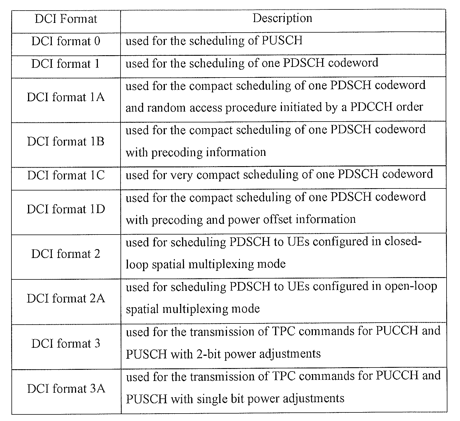
DCI 포맷 0은 상향링크 자원 할당 정보를 가리키고, DCI 포맷 1~2는 하향링크 자원 할당 정보를 가리키고, DCI 포맷 3, 3A는 임의의 단말 그룹들에 대한 상향링크 TPC(transmit power control) 명령을 가리킨다.
도 5의 (b)를 참조하면, 상향링크 서브프레임은 주파수 영역에서 제어 영역 및 데이터 영역으로 나누어질 수 있다. 제어 영역은 상향링크 제어 정보를 나르는 PUCCH(Physical Uplink Control CHannel)로 할당된다. 데이터 영역은 사용자 데이터를 나르기 위한 PUSCH(Physical Uplink Shared CHannel)로 할당된다. 단일 반송파 특성을 유지하기 위하여, 하나의 단말은 PUCCH 및 PUSCH를 동시에 전송하지 않는다. 하나의 단말을 위한 PUCCH는 하나의 서브프레임에서 RB 페어로 할당된다. RB 페어에 속하는 RB들은 각 2개의 슬롯에서 서로 다른 부반송파를 차지하고 있다. PUCCH에 할당된 RB 페어는 슬롯 경계(slot boundary)에서 주파수 호핑된다.Referring to FIG. 5B, the UL subframe may be divided into a control region and a data region in the frequency domain. The control region is allocated to a PUCCH (Physical Uplink Control CHannel) carrying uplink control information. The data area is allocated to a PUSCH (Physical Uplink Shared CHannel) for carrying user data. To maintain single carrier characteristics, one terminal does not transmit PUCCH and PUSCH at the same time. The PUCCH for one UE is allocated to an RB pair in one subframe. RBs belonging to the RB pair occupy different subcarriers in each of the two slots. The RB pair assigned to the PUCCH is frequency hopped at the slot boundary.
도 6은 이동통신 시스템의 일 예인 3GPP LTE 시스템에서 사용되는 하향링크의 시간-주파수 자원 격자 구조(resource grid structure)를 나타낸 도면이다.6 is a diagram illustrating a downlink time-frequency resource grid structure used in a 3GPP LTE system, which is an example of a mobile communication system.
각 슬롯에서 전송되는 하향링크 신호는 ![]()
![]()
![]()
![]()
![]()
![]()
![]()
![]()
![]()
![]()
![]()
![]()
![]()
![]()
![]()
![]()
![]()
![]()
![]()
![]()
![]()
![]()
![]()
![]()
![]()
![]()
![]()
![]()
각 안테나 포트에 대한 자원 격자 내의 각 요소는 자원 요소(RE: Resource Element)라고 불리우며, 슬롯 내의 인덱스 쌍 (k,l)에 의해 유일하게 식별된다. 여기서, k는 주파수 영역에서의 인덱스이고, l는 시간 영역에서의 인덱스이며 k는 0,...,![]()
![]()
![]()
![]()
도 6에 도시된 자원 블록은 어떤 물리 채널과 자원 요소들 간의 매핑(mapping) 관계를 기술하기 위해 사용된다. RB는 물리 자원 블록(PRB: Physical Resource Block)과 가상 자원 블록(VRB: Virtual Resource Block)으로 나눌 수 있다. 상기 하나의 PRB는 시간 영역의 ![]()
![]()
![]()
![]()
![]()
![]()
![]()
![]()
![]()
![]()
![]()
![]()
![]()
![]()
![]()
![]()

PRB는 주파수 영역에서 0에서 ![]()

![]()
상기 VRB의 크기는 PRB의 크기와 같다. VRB는 로컬형 VRB(Localized VRB, LVRB)와 분산형 VRB(Distributed VRB, DVRB)로 나뉘어 정의될 수 있다. 각 타입의 VRB에 대해, 하나의 서브프레임 내의 두 개의 슬롯에 있는 한 쌍의 VRB는 단일 VRB 넘버 nVRB가 함께 할당된다. The size of the VRB is equal to the size of the PRB. The VRB can be defined by dividing into a localized VRB (Localized VRB) and a distributed VRB (Distributed VRB). For each type of VRB, a pair of VRBs in two slots in one subframe are assigned together with a single VRB number n VRB .
상기 VRB은 PRB과 동일한 크기를 가질 수 있다. 두 가지 타입의 VRB이 정의되는데, 첫째 타입은 로컬형 VRB(Localized VRB, LVRB)이고, 둘째 타입은 분산형 VRB(Distributed VRB, DVRB)이다. 각 타입의 VRB에 대해, 한 쌍(pair)의 VRB이 단일의 VRB 인덱스 (이하, VRB 넘버(number)로 지칭될 수도 있다)를 가지고 1개의 서브프레임의 2개의 슬롯에 걸쳐 할당된다. 다시 말하면, 하나의 서브프레임을 구성하는 2개의 슬롯 중 제 1 슬롯에 속하는 ![]()
![]()
![]()
![]()
![]()
![]()
![]()
![]()
이하에서 이동통신 시스템에서 송신단 및 수신단 사이에서 송수신되는 참조신호(Reference Signal, RS)에 대해 설명한다.Hereinafter, a reference signal (RS) transmitted and received between a transmitting end and a receiving end in a mobile communication system will be described.
이동통신 시스템에서 송신단이 수신단으로 패킷(혹은 신호)을 전송할 때, 송신단이 전송하는 패킷은 무선 채널을 통해서 전송되기 때문에 전송과정에서 신호의 왜곡이 발생할 수 있다. 이렇게 왜곡된 신호를 수신단에서 올바로 수신하기 위해서, 수신단은 채널 정보를 알아내어 수신 신호에서 그 채널 정보만큼 전송 신호의 왜곡을 보정함으로써 올바른 신호를 수신할 수 있는 것이다. 이렇게 채널의 정보를 알아내기 위해서는 송신단과 수신단에서 모두 알고 있는 신호를 전송할 필요가 있다. 즉, 수신단에서 알고 있는 신호가 채널을 통해 수신될 때 그 신호의 왜곡 정도를 가지고 채널의 정보를 알아내는 방법을 주로 사용하는데, 이때 전송되는 송신측과 수신측이 모두 알고 있는 신호를 참조신호 또는 파일럿 신호 (Pilot Signal)라고 한다. In a mobile communication system, when a transmitting terminal transmits a packet (or a signal) to a receiving terminal, a packet transmitted by the transmitting terminal is transmitted through a wireless channel, so that a signal may be distorted during transmission. In order to correctly receive the distorted signal at the receiving end, the receiving end can receive the correct signal by determining the channel information and correcting the distortion of the transmission signal by the channel information in the received signal. In order to obtain information of the channel, it is necessary to transmit a signal known to both the transmitting end and the receiving end. That is, when a signal known to the receiving end is received through a channel, a method of finding information of the channel with a degree of distortion of the signal is mainly used. At this time, a signal known to both the transmitting end and the receiving end is referred to as a reference signal It is called a pilot signal.
기존에는 송신단이 수신단으로 패킷을 전송할 때, 지금까지 한 개의 송신안테나와 한 개의 수신안테나를 사용했었다. 그러나 또한, 최근 대부분의 이동통신 시스템에서는 다중 송신안테나와 다중 수신안테나를 채택해 송수신 데이터 효율을 향상시킬 수 있는 방법을 사용한다. 이동통신 시스템의 송신단 혹은 수신단에서 용량증대, 통신 성능을 개선하기 위해서 다중안테나를 사용하여 데이터를 송수신하는 경우에, 각 송신안테나 별로 별도의 참조신호가 존재한다. 수신단은 알고 있는 각 송신 안테나 별 참조신호를 이용하여 각 송신안테나로부터 전송된 신호를 잘 수신할 수 있다.In the past, when a transmitting terminal transmits a packet to a receiving terminal, one transmitting antenna and one receiving antenna have been used so far. However, in most recent mobile communication systems, a method of improving transmit / receive data efficiency by employing multiple transmit antennas and multiple receive antennas is used. In the case of transmitting and receiving data using multiple antennas in order to improve the capacity and communication performance at the transmitting end or the receiving end of the mobile communication system, there is a separate reference signal for each transmission antenna. The receiving end can receive the signals transmitted from the respective transmitting antennas by using the known reference signals for the respective transmitting antennas.
이동통신 시스템에서 참조신호는 그 목적에 따라 크게 두 가지로 구분될 수 있다. 참조신호에는 채널 정보 획득을 위한 목적을 위한 것과 데이터 복조를 위해 사용되는 것이 있다. 전자는 단말이 하향링크로의 채널 정보를 획득할 수 있는데 그 목적이 있으므로, 광대역으로 전송될 필요가 있으며, 특정 서브 프레임에서 하향링크 데이터를 수신하지 않는 단말이라도 그 참조신호를 수신하고 측정할 수 있어야 한다. 또한 이러한 채널 측정용 참조신호는 핸드 오버의 측정 등을 위해서도 사용될 수 있다. 후자는 기지국이 하향링크 신호를 전송할 때 해당 자원에 함께 보내는 참조신호로서, 단말은 해당 참조신호를 수신함으로써 채널 추정을 할 수 있고, 따라서 데이터를 복조할 수 있게 된다. 이러한 복조용 참조신호는 데이터가 전송되는 영역에 전송되어야 한다.In a mobile communication system, reference signals can be roughly classified into two types according to their purposes. The reference signal is used for the purpose of obtaining channel information and for data demodulation. Since the former can acquire channel information on the downlink, the former needs to be transmitted in a wide band, and even a terminal that does not receive downlink data in a specific subframe can receive and measure the reference signal. . The reference signal for channel measurement can also be used for measurement of handover and the like. The latter is a reference signal transmitted together with a corresponding resource when the base station transmits the downlink signal. The terminal can perform channel estimation by receiving the reference signal, and thus can demodulate the data. These demodulation reference signals must be transmitted in the area where data is transmitted.
이동통신 시스템의 일 예인 Release 8 LTE 시스템에서는 유니캐스트 서비스를 위해서 두 가지 종류의 하향링크 참조신호가 정의되어 있다. 채널 상태에 대한 정보 획득 및 핸드오버 등의 측정 등을 공동 참조신호(CRS: Common Reference Signal, 이하 ‘CRS’라고 함)와 데이터 복조를 위해 사용되는 전용 참조신호(DRS: Dedicated RS, ‘이하 DRS’라 칭함) (UE-specific 참조신호에 해당함)라고 불리우는 두 가지의 참조신호가 있다. Release 8 LTE 시스템에서 UE-specific 참조신호는 데이터 복조용으로만 사용되며 CRS는 채널 정보 획득 및 데이터 복조의 두 가지 목적으로 다 사용된다. 이 CRS는 셀-특정(cell-specific) 참조신호로서, 기지국은 광대역에 걸쳐 매 서브 프레임마다 CRS를 전송한다. 셀-특정(Cell-specific) CRS는 기지국의 전송 안테나 개수에 따라서 최대 4개의 안테나 포트에 대한 참조신호가 전송된다. 예를 들어, 기지국의 송신 안테나의 개수가 2개일 경우, 0번과 1번 안테나 포트에 대한 CRS가 전송되고, 4개인 경우에는 0 내지 3 번 안테나 포트에 대한 CRS가 각각 전송된다. 기지국의 송신 안테나가 4개일 경우 한 자원블록(Resource Block, RB)에서의 CRS 패턴은 도 7에 도시된 바와 같다.In the
도 7은 이동통신 시스템의 일 예인 3GPP LTE 시스템에서의 CRS 패턴을 나타낸 도면이다.7 is a diagram illustrating a CRS pattern in a 3GPP LTE system, which is an example of a mobile communication system.
도 7의 (a)에 도시된 바와 같이, 4개 안테나 포트에 대한 CRS(R0, R1, R2, R3)는 1RB 에서 시간-주파수 자원이 중첩되지 않도록 할당된다. LTE 시스템에서 CRS가 시간-주파수 자원에 맵핑될 때에는, 주파수 축에서 한 안테나 포트에 대한 참조신호는 6 RE(Resource Element)당 1개의 RE에 맵핑되어 전송된다. 한 RB가 주파수 축에서 12개의 RE로 구성되어 있으므로 한 안테나 포트에 대한 RE는 한 RB당 2개의 RE가 사용된다. As shown in FIG. 7A, CRS (R0, R1, R2, R3) for four antenna ports are allocated so that time-frequency resources do not overlap in 1RB. In a LTE system, when a CRS is mapped to a time-frequency resource, a reference signal for one antenna port on the frequency axis is mapped to one RE per 6 REs (Resource Element). Since one RB is composed of 12 REs on the frequency axis, RE for one antenna port uses 2 REs per RB.
도 7의 (b)에는 O번 안테나 포트 0번에 대한 참조신호인 R0가 1 RB내에서의 패턴을 나타내고 있다.In FIG. 7 (b), R0, which is a reference signal for the
LTE 시스템의 진화 발전된 형태인 LTE-A 시스템에서는 기지국이 하향링크 전송을 위해 최대 8개의 송신 안테나를 지원할 수 있도록 설계되어야 한다. 따라서 최대 8개 송신 안테나에 대한 참조신호도 또한 지원되어야 한다. LTE 시스템에서 하향링크 참조신호는 최대 4개의 안테나 포트에 대한 참조신호만 정의되어 있으므로, LTE-A 시스템에서 기지국이 4개 이상 최대 8개의 하향링크 송신 안테나를 가질 경우 이들 안테나 포트에 대한 참조신호가 추가적으로 정의되고 설계되어야 한다. 최대 8개의 송신 안테나 포트에 대한 참조신호는 상술한 바 있는 채널 측정을 위한 참조신호와 데이터 복조를 위한 참조신호 두 가지가 모두 설계되어야 한다. Evolution of LTE system In LTE-A system, the base station should be designed to support up to 8 transmit antennas for downlink transmission. Therefore, reference signals for up to 8 transmit antennas should also be supported. In the LTE system, only a reference signal for up to four antenna ports is defined in the LTE system. Therefore, when the base station has more than four downlink transmission antennas and up to eight downlink transmission antennas in the LTE-A system, Must be additionally defined and designed. The reference signal for up to 8 transmit antenna ports must be designed in both of the reference signal for channel measurement and the reference signal for data demodulation.
LTE-A 시스템을 설계함에 있어서 중요한 고려 사항 중 하나는 하위 호환성(backward compatibility)이다. 즉, LTE 단말이 LTE-A 시스템에서도 무리 없이 잘 동작해야 하고, 시스템 또한 이를 지원해야 한다는 것이다. 참조신호 전송 관점에서 보았을 때, LTE에서 정의되어 있는 CRS가 전 대역으로 매 서브프레임마다 전송되는 시간-주파수 영역에서 추가적으로 최대 8개의 송신 안테나 포트에 대한 참조신호가 추가적으로 정의될 필요가 있다. 그러나, LTE-A 시스템에서 기존 LTE 시스템의 CRS와 같은 방식으로 최대 8개의 송신 안테나에 대한 참조신호 패턴을 매 서브프레임마다 전 대역에 추가하게 되면 참조신호 전송에 따른 오버헤드가 지나치게 커지게 된다. One of the important considerations in designing an LTE-A system is backward compatibility. That is, the LTE terminal should work well in the LTE-A system, and the system should also support it. It is necessary to additionally define reference signals for up to eight transmit antenna ports in the time-frequency domain in which the CRS defined in LTE is transmitted for every subframe in all bands as viewed from the viewpoint of reference signal transmission. However, if a reference signal pattern for up to 8 transmit antennas is added to all bands in every subframe in the same manner as CRS of the existing LTE system in the LTE-A system, overhead due to reference signal transmission becomes too large.
따라서 LTE-A 시스템에서 새롭게 설계하는 참조신호는 크게 두 가지 분류로 나누게 되는데, 변조 및 코딩 방식(Modulation and Coding Scheme, MCS), 프리코딩 행렬 지시자(Precoding Matrix Index, PMI) 등의 선택을 위한 채널 측정 목적의 참조신호인(CSI-RS: Channel State Information-RS, 이하 ‘CSI-RS’ 라 칭함)(Channel State Indication-RS 등으로도 호칭됨)와 8개의 송신 안테나로 전송되는 데이터 복조를 위한 참조신호(DM-RS: Data deModulation?RS, 이하 ‘DM-RS’라 칭함)가 있다. 채널 측정 목적의 CSI-RS는 기존의 CRS가 채널 측정, 핸드 오버 등의 측정 등의 목적과 동시에 데이터 복조를 위해 사용되는 것과 달리 채널 측정 위주의 목적을 위해서 설계되었다는 것에 특징이 있다. 물론 CSI-RS는 또한 핸드 오버 등의 측정 등의 목적으로도 사용될 수도 있다. CSI-RS가 채널 상태에 대한 정보를 얻는 목적으로만 전송되므로 CRS와 달리 매 서브프레임마다 전송되지 않아도 된다. 따라서, CSI-RS 전송에 따른 오버헤드를 줄이기 위하여 기지국은 CSI-RS를 시간 축 상에서 간헐적으로 전송하고, 데이터 복조를 위해서는 해당 시간-주파수 영역에서 스케줄링된 단말에게 전용으로(dedicated) DM-RS를 전송한다. 즉, 특정 단말의 DM-RS는 해당 단말이 스케줄링된 영역, 즉 데이터를 수신할 수 있는 시간-주파수 영역에만 전송되는 것이다. Therefore, the reference signal newly designed in the LTE-A system can be divided into two categories: a channel for selecting a modulation and coding scheme (MCS), a precoding matrix index (PMI) (CSI-RS) (also referred to as a Channel State Indication-RS or the like) which is a reference signal for measurement purposes and a demodulator for demodulating data transmitted through eight transmission antennas And a reference signal (DM-RS: Data deModulation? RS, hereinafter referred to as DM-RS). The CSI-RS for channel measurement purposes is characterized in that the existing CRS is designed for channel measurement-oriented purposes, unlike that used for data demodulation purposes, such as measurement of channel measurement, handover, and the like. Of course, the CSI-RS can also be used for measurement purposes such as handover. Unlike the CRS, the CSI-RS is not transmitted every subframe since it is transmitted only for the purpose of obtaining information on the channel state. Therefore, in order to reduce the overhead due to the CSI-RS transmission, the BS intermittently transmits the CSI-RS on the time axis and a DM-RS dedicated to the scheduled UE in the corresponding time- send. That is, the DM-RS of a specific terminal is transmitted only in a time-frequency domain in which the terminal can receive the scheduled domain, i.e., data.
LTE-A 시스템에서 CSI-RS 전송에 관한 구체적인 설계는 아직 결정되지 않았으나, 기지국은 모든 안테나 포트에 대한 CSI-RS를 전송해야 한다. 기지국이 최대 8개의 송신 안테나 포트에 대한 CSI-RS를 매 서브프레임마다 전송하는 것은 오버헤드가 너무 큰 문제가 있기 때문에, 기지국은 CSI-RS를 매 서브프레임마다 전송하지 않고 시간 축에서 간헐적으로 전송함으로써 오버헤드를 줄일 수 있다. 즉, 기지국은 CSI-RS를 한 서브 프레임의 정수 배의 주기를 가지고 주기적으로 전송하거나 특정 전송 패턴으로 전송할 수 있다. 이때 기지국은 CSI-RS의 전송 주기나 패턴을 구성(configure) 할 수 있다. The specific design of the CSI-RS transmission in the LTE-A system has not yet been determined, but the base station must transmit the CSI-RS for all antenna ports. Since the base station transmits the CSI-RS for each of the maximum eight transmit antenna ports every subframe, there is a problem that the overhead is too large. Therefore, the base station intermittently transmits the CSI- The overhead can be reduced. That is, the base station can periodically transmit the CSI-RS with a period of an integral multiple of one subframe or transmit it in a specific transmission pattern. At this time, the base station can configure the transmission period or pattern of the CSI-RS.
단말이 CSI-RS를 측정하기 위해서 반드시 자신이 속한 셀의 각 안테나 포트에 대한 CSI-RS의 시간-주파수 위치, CSI-RS 시퀀스, CSI-RS 주파수 쉬프트(frequency shift) 등에 대한 정보를 알고 있어야 한다. CSI-RS는 하향링크 채널 정보를 알기 위한 목적으로 전송되므로 DRS와 달리 전 대역으로 전송되어야 한다. 그러면 단말은 수신한 CSI-RS를 이용하여 각 대역의 CQI, PMI, 랭크(Rank) 등의 채널 정보를 기지국에 피드백하고, 기지국은 피드백받은 채널 정보를 이용하여 스케줄링 동작을 수행하게 되는 것이다. 그런데 LTE-A 단말을 위한 CSI-RS를 LTE 단말에게도 전송하는 것은 오버헤드가 될 수 있다. 그 이유는, LTE 단말은 CSI-RS의 존재를 모를 뿐 더러, LTE 단말에게 스케줄링 자원 영역에서는 CSI-RS가 전송되는 경우 기지국이 해당 RE들을 펑처링(puncturing)해서 보내기 때문이다. In order to measure the CSI-RS, the UE must know information on the time-frequency location, the CSI-RS sequence, the CSI-RS frequency shift, and the like of the CSI-RS with respect to each antenna port of the cell to which the UE belongs . Since the CSI-RS is transmitted for the purpose of knowing downlink channel information, it should be transmitted to all bands unlike DRS. Then, the UE feeds channel information such as CQI, PMI, and rank of each band to the base station using the received CSI-RS, and the base station performs the scheduling operation using the feedback channel information. However, transmitting the CSI-RS for the LTE-A terminal to the LTE terminal may be an overhead. The reason for this is that the LTE UE does not know the existence of the CSI-RS and punishes the REs when the CSI-RS is transmitted to the LTE UE in the scheduling resource region.
따라서, 본 발명에서는 CSI-RS가 LTE 단말에게 미치는 영향을 최소화시키고 시스템 전체에 미치는 CSI-RS의 오버헤드를 줄이는 방법으로써 CSI-RS를 여러 부대역(subband)으로 나누어서 보내는 방식을 제안한다. Therefore, the present invention proposes a method of dividing the CSI-RS into several subbands as a method of minimizing the influence of the CSI-RS on the LTE terminal and reducing the overhead of the CSI-RS over the entire system.
도 8은 이동통신 시스템의 일 예인 3GPP LTE 시스템에서 CSI-RS가 전송되는 시간-주파수 위치의 일 예를 나타낸 도면이다.8 is a diagram illustrating an example of a time-frequency location in which a CSI-RS is transmitted in a 3GPP LTE system, which is an example of a mobile communication system.
도 8을 참조하면, 기지국이 특정 서브 프레임에서 CSI-RS가 전송할 때, 전 대역을 통해 CSI-RS를 전송하지 않고 일부 대역에서만 전송할 수 있다. 즉, 전 대역을 여러 개의 부대역으로 나눈 후, 각 부대역에 대한 CSI-RS가 서로 다른 시점에 전송되는 것이다. Referring to FIG. 8, when a base station transmits a CSI-RS in a specific subframe, it can transmit only a part of a band without transmitting CSI-RS over the entire band. That is, after dividing the entire band into several subbands, the CSI-RS for each subband is transmitted at different points in time.
도 8에 도시된 바와 같이, 전체 대역을 N개의 부 대역으로 나누었다고 하자. 각 N개의 부대역에서의 CSI-RS는 각각 CSI-RS전송 주기를 가지고 있다. 그리고 각 N개의 부대역에서의 CSI-RS는 서로 다른 전송시간 옵셋(offset)을 갖는다. 이 옵셋을 통해서 각 부대역에서의 CSI-RS가 서로 다른 시점에 전송될 수 있게 된다. 여기서 옵셋이라고 함은 각 부대역의 시작점부터 처음 CSI-RS가 전송되는 시점까지의 간격을 말한다. 기지국은 하향링크 전 대역을 3개의 부대역으로 나누어서 CSI-RS를 전송할 수 있다. 부대역 1, 부대역 2, 부대역 3에서 전송되는 CSI-RS를 각각 CSI-RS1, CSI-RS2, CSI-RS3이라 하고, CSI-RS 1 내지 3은 전송시점에 대한 서로 다른 오프셋 값, 옵셋 1 내지 3을 각각 갖는다. 그리고, CSI-RS 1 내지 3은 각각의 CSI-RS 전송 주기인, 주기 1 내지 3을 가지고 그 값을 주기로 해서 CSI-RS가 각 부대역에서 전송될 수 있다. 이때, 옵셋 1 내지 3은 모두 같은 값을 가질 수 있으며, 이 경우에는 CSI-RS가 부대역으로 나누어서 전송되는 것이 아니라 전 대역에 동시에 전송된다. 또한, 각 부대역의 CSI-RS 전송주기인 주기 1 내지 3은 하나의 파라미터, CSI-RS 주기로 운영될 수도 있다. 즉, 모든 부대역에서의 CSI-RS 주기는 동일하게 운영될 수 있다. CSI-RS는 셀-특정(cell-specific)한 정보이므로, 기지국은 셀 내 단말에게 CSI-RS에 대한 정보를 방송해 주어야 한다. 이때, 기지국이 방송하는 정보는 CSI-RS가 전송되는 부대역의 개수(N), 각 부대역 별 CSI-RS 전송 옵셋, CSI-RS 주기를 포함할 수 있다. Assume that the entire band is divided into N subbands as shown in FIG. Each CSI-RS in each of the N subbands has a CSI-RS transmission period. And the CSI-RS in each of the N subbands has a different transmission time offset. Through this offset, the CSI-RS in each sub-band can be transmitted at different points in time. Here, the offset refers to the interval from the starting point of each subband to the transmission of the first CSI-RS. The base station can transmit the CSI-RS by dividing the entire downlink band into three subbands.
기지국이 도 8에 도시된 패턴과 같이 CSI-RS를 전송하면, 단말은 CSI-RS를 측정해서 하향링크 채널 상태를 파악하고 이에 대한 채널 정보(CQI, PMI, RI(Rank Indicator), 등)를 기지국에 피드백 할 수 있다. 그러면, 기지국은 단말로부터의 피드백 정보를 이용해서 어떤 주파수 대역에 어떤 단말에게 어떤 MCS(Modulation and Coding Scheme)을 사용하여 어떤 공간(space)으로 데이터를 전송할 것인지 등을 스케줄링을 수행한다. 그러나, 상술한 바와 같이, 기지국이 CSI-RS를 부대역으로 나누어 전송하게 되면, 단말은 CSI-RS가 전송되는 특정 대역에 대한 채널 정보만을 획득하게 되어 특정 대역에 대한 채널 정보(CQI, PMI, RI 등)만을 기지국에 보낼 수 밖에 없다. 결국 기지국도 전 대역에 대해서 스케줄링을 수행할 수 없는 문제가 생긴다. 만약, 기지국이 전 대역에 대해서 스케줄링을 수행한다 하더라도, CSI-RS가 전송되는 부대역 이외의 부대역의 채널 정보가 없거나 부정확한 상태에서 스케줄링을 하게 되므로 시스템의 성능이 저하될 수 있다. When the BS transmits the CSI-RS as shown in FIG. 8, the UE measures the CSI-RS to determine the downlink channel state and transmits channel information (CQI, PMI, RI (Rank Indicator) Feedback to the base station. Then, the base station performs feedback scheduling using a modulation and coding scheme (MCS) to a certain frequency band in which frequency band the data is to be transmitted using a feedback information from the mobile station. However, as described above, when the BS divides the CSI-RS into subbands, the MS only acquires channel information for a specific band to which the CSI-RS is transmitted, and obtains channel information (CQI, PMI, RI, etc.) to the base station. As a result, there is a problem that the base station can not perform scheduling for all bands. Even if the base station performs scheduling for all bands, the performance of the system may be degraded because there is no channel information of the subbands other than the subbands in which the CSI-RS is transmitted, or the scheduling is performed in an incorrect state.
따라서, 이러한 문제를 해결하기 위한 방안으로 DRS(DM-RS라고도 불림)를 이용한 채널 피드백을 제안한다. 즉, 단말이 하향링크의 채널 상태를 측정하는 방법으로서 하향링크 데이터 복조를 위해 하향링크 데이터가 스케줄링 영역에서 데이터와 함께 전송되는 DRS를 이용하여 채널을 측정하고 이를 기지국에 피드백한다.Therefore, we propose channel feedback using DRS (also referred to as DM-RS) as a solution to this problem. That is, as a method for measuring a channel state of a downlink, a UE measures a channel using DRS transmitted with data in a scheduling region for downlink data demodulation and feeds back the measured channel to the base station.
기지국은 참조신호 전송에 따른 오버헤드를 줄이기 위하여 CSI-RS를 매 서브프레임 단위로 전송하지 않고 서브프레임의 배수 단위의 주기를 가지고 전송한다. 이와 달리, 기지국은 데이터와 DRS를 함께 항상 전송한다. 이와 별개로 DRS는 CQI 등의 피드백으로 채널 상태를 측정하는 것 보다 정확한 채널 상태를 얻어내기 위한 추가적인 목적으로 사용될 수 있다. In order to reduce the overhead due to the transmission of the reference signal, the base station transmits the CSI-RS with a period of a multiple of the subframe, instead of transmitting every CSI-RS. Alternatively, the base station always transmits data and DRS together. Separately, DRS can be used as an additional purpose to obtain a more accurate channel state than to measure the channel state with feedback such as CQI.
기지국이 단말로 CSI-RS를 전송하고, 단말은 해당 CSI-RS를 수신하여 하향링크 채널에 대한 최적의 채널품질정보(CQI(Channel Quality Information), PMI(채널 direction 정보) 등)을 결정하여 기지국으로 피드백할 수 있다. 기지국은 셀 내에 있는 각 단말로부터 채널 정보를 수신한 뒤, 단말에 특정 시간-주파수 자원을 할당하고, 보고된 채널 정보를 기반으로 프리코더(precoder)와 송신 데이터의 MCS 레벨을 결정할 수 있다. 기지국은 각 단말로부터 피드백 받은 채널 정보를 이용하여 하향링크 데이터를 전송할 단말을 스케줄링하고, 기지국은 스케줄링된 단말에게 PDSCH를 보낼 때 DRS(DM-RS)(이하에서는 ‘DM-RS’로 통일하기로 한다)도 함께 보내야 한다. The base station transmits CSI-RS to the UE, and the UE receives the corresponding CSI-RS to determine optimal channel quality information (CQI (Channel Quality Information), PMI (channel direction information), etc.) for the downlink channel, . ≪ / RTI > After receiving the channel information from each terminal in the cell, the base station allocates a specific time-frequency resource to the terminal, and can determine the MCS level of the precoder and the transmission data based on the reported channel information. The base station schedules a terminal to transmit downlink data using channel information fed back from each terminal, and when the base station transmits a PDSCH to the scheduled terminal, the base station uses a DRS (DM-RS) Should also be sent.
현재, 이동통신 시스템 표준의 일 예인 LTE 표준, IEEE 802.16m 표준 방식에서는 채널 정보가 보고된 각 셀마다 프리코더(procoder)가 독자적으로 결정되고 단일 사용자가 특정 시간-주파수 자원을 사용하도록 제한함으로써, 통상적인 경우 보고된 PMI와 CQI는 별다른 변경 없이 각 셀의 기지국이 그대로 사용할 가능성이 높다. 즉, 단말이 기지국에게 전송한 채널 정보는 채널이 크게 변하지 않는 시간 내에서 유효한 정보라고 할 수 있다. 따라서 채널이 크게 변하지 않는 한 단말은 이에 대한 정보를 상향링크 채널을 통해 계속적으로 알려줄 필요가 없고, 이를 위한 제어 시그널링도 존재하지 않는다.At present, in the LTE standard and the IEEE 802.16m standard, which are an example of a mobile communication system standard, a procoder is independently determined for each cell in which channel information is reported, and a single user is restricted to use a specific time-frequency resource, In a typical case, the reported PMI and CQI are likely to be used by base stations of each cell without any modification. That is, the channel information transmitted from the terminal to the base station can be considered to be valid within a time period when the channel is not largely changed. Therefore, as long as the channel does not change significantly, the UE does not need to continuously inform information on the uplink channel, and there is no control signaling for this.
차세대 이동통신 시스템의 표준인 LTE-A 시스템에서는 데이터 전송률 향상을 위해 기존 표준에서는 지원되지 않았던 CoMP(Coordinated Multi Point) 방식, Multi User-MIMO(MU-MIMO) 방식을 지원할 것으로 예상된다. 여기서, CoMP 시스템은 음영 지역에 있는 단말 및 기지국(셀 또는 섹터) 간의 통신성능을 향상시키기 위해 2개 이상의 기지국 혹은 셀이 서로 협력하여 단말과 통신하는 시스템을 말한다. CoMP 방식은 데이터 공유를 통한 협력적 MIMO 형태의 조인트 프로세싱(CoMP-JP: CoMP-Joint Processing) 및 협력 스케줄링/빔포밍(CoMP-CS: CoMP-Coordinated Scheduling/beamforming)방식으로 구분할 수 있다. 조인트 프로세싱(CoMP-JP) 방식에서, 단말은 CoMP를 수행하는 각 기지국으로부터 데이터를 순간적으로 동시에 수신할 수 있으며, 각 기지국으로부터의 수신한 신호를 결합하여 수신 성능을 향상시킬 수 있다. 이와 달리, 협력 스케줄링/빔포밍 방식(CoMP-CS)에서, 단말은 빔포밍을 통해 데이터를 순간적으로 하나의 기지국을 통해서 수신할 수 있다. MU-MIMO 기술은 기지국이 각 안테나 자원을 다른 단말에게 할당하는 것으로, 안테나 별로 고속 데이터 전송률이 가능한 단말을 선택하여 스케줄링하는 방식이다. 이러한 MU-MIMO 방식은 시스템 처리율(system throughput)을 향상시키는 기술이다. In the LTE-A system, which is a standard of the next generation mobile communication system, Coordinated Multi Point (CoMP) method and Multi User-MIMO (MU-MIMO) method, which are not supported in the existing standard, are expected to be supported. Here, the CoMP system refers to a system in which two or more base stations or cells cooperate with each other to improve communication performance between a terminal and a base station (cell or sector) in a shadow area. The CoMP scheme can be classified into cooperative MIMO type joint processing (CoMP-JP: CoMP-Joint Processing) and CoMP-Coordinated Scheduling / beamforming (CoMP-CS) In the joint processing (CoMP-JP) scheme, the UE can instantaneously receive data simultaneously from each base station that performs CoMP, and can combine received signals from each base station to improve reception performance. Alternatively, in the cooperative scheduling / beamforming scheme (CoMP-CS), the UE can receive data via beamforming through one base station instantaneously. In the MU-MIMO technique, a base station allocates each antenna resource to another UE, and selects and schedules a UE capable of a high data rate for each antenna. This MU-MIMO scheme is a technique for improving system throughput.
LTE-A 시스템에서 이러한 향상된 송신 기술을 적용할 경우 단말이 보고한 PMI는 하향링크 전송을 위한 참고 정보로 쓰일 뿐, 그대로 사용되지 않을 가능성이 높다. 즉, 단말이 보고한 PMI는 실제 하향링크 전송을 위한 프리코더(precoder)와 다르며 그 결과 단말이 보고한 CQI는 단말에서 실제 수신 시 얻을 수 있는 CQI와는 다른 값이 될 수 있다. 따라서 이러한 환경에서는 단말은 기지국이 사용한 프리코더(precoder)를 바탕으로 CQI를 재계산하여 기지국으로 피드백할 필요성이 있다. 단말은 하향링크 데이터 영역에 고르게 분포한 DM-RS를 이용하여 CSI(Channel State Information), CQI 등을 재계산할 수 있다. 이와 같이, PDSCH를 수신하는 단말에게 DM-RS를 이용하여 채널 정보를 계산하고 이를 피드백 하게 함으로써, 기지국은 보다 정확한 채널 정보를 얻을 수 있다. In the LTE-A system, when the enhanced transmission technology is applied, the PMI reported by the UE is used as reference information for downlink transmission, and is likely not to be used as it is. That is, the PMI reported by the UE is different from the precoder for the actual downlink transmission, and as a result, the CQI reported by the UE may be different from the CQI that can be obtained in the UE in actual reception. Therefore, in such an environment, the UE needs to recalculate the CQI based on a precoder used by the base station and feed back the calculated CQI to the base station. The UE can recalculate CSI (Channel State Information), CQI, and the like using DM-RSs uniformly distributed in the downlink data region. As described above, the terminal receiving the PDSCH calculates channel information using the DM-RS and feeds back the channel information, so that the base station can obtain more accurate channel information.
도 9는 본 발명에 따른 DM-RS를 이용한 채널 정보를 피드백하는 방식의 일 예를 나타낸 도면이다. 9 is a diagram illustrating an example of a method of feeding back channel information using a DM-RS according to the present invention.
도 9에서는 상향링크와 하향링크가 주파수 분할 듀플렉스(Frquency Division Duplex, FDD) 방식으로 운용되는 경우를 예로 들어 설명하였지만, 본 발명은 이에 제한되지 않으며 시간 분할 듀플렉스(Time Division Duplex, TDD) 방식에서도 동일하게 적용 가능하다. 점선으로 표시된 화살표는 하향링크 송신을 위한 기존 제어 신호와 절차를 나타낸 것이며, 실선으로 표시된 화살표는 CQI 갱신을 위해 새롭게 추가된 제어 신호와 절차를 나타낸 것이다. 9, an uplink and a downlink are operated in a frequency division duplex (FDD) scheme. However, the present invention is not limited to this and is also applicable to a time division duplex (TDD) scheme Lt; / RTI > Arrows indicated by dashed lines represent existing control signals and procedures for downlink transmission, and solid arrows represent newly added control signals and procedures for CQI update.
기지국은 단말로 CSI-RS를 전송하고, 특정 단말에게 채널 정보를 피드백 할 수 있도록 UL grant를 전송한다(S910). 단말이 CSI-RS를 수신하고 이에 대한 각 부대역 별 CQI, PMI 등을 결정하고 UL grant에서 지시하는 시간, 주파수 자원을 이용하여 결정된 채널 정보를 기지국으로 피드백 한다(S920). 조인트 전송(Joint transmission) 혹은 빔 회피(beam avoidance) 등 협력 셀과의 CoMP를 수행할 때, 단말은 서빙 셀의 PMI와 협력 셀의 PMI를 모두 고려해야 하기 때문에 PMI와 CQI 계산량도 늘어날 것으로 예상된다. 단말의 용량(capability)과 PMI 크기에 따라 처리 시간(processing time)이 다르겠지만, 이에 대한 계산이 3ms 내에 가능할 것으로 가정하여, 단말이 CSI-RS 수신 후 4ms 뒤 특정 주파수에 UL grant를 주어 주기적으로 피드백을 수행하도록 할 수 있다.The base station transmits the CSI-RS to the terminal and transmits a UL grant so that channel information can be fed back to the specific terminal (S910). In step S920, the UE receives the CSI-RS and determines CQI, PMI, and the like for each sub-band, and feeds the channel information determined using the time and frequency resources indicated in the UL grant to the base station in step S920. When performing CoMP with cooperative cells such as joint transmission or beam avoidance, the PMI and the CQI calculation amount are expected to increase because the UE must consider both the PMI of the serving cell and the PMI of the cooperative cell. Assuming that the processing time differs depending on the capability of the UE and the PMI size, it is assumed that the calculation can be performed within 3ms, and the UE gives an UL grant to a specific frequency 4ms after receiving the CSI-RS, Feedback can be performed.
기지국은 각 단말로부터 피드백 받은 채널 정보를 이용하여 하향링크 데이터를 전송할 단말을 스케줄링하고, 스케줄링된 해당 단말에게 PDSCH를 보낼 때 DM-RS도 함께 보내야 한다(S930). CSI-RS는 시간축 상에서 간헐적으로 전송되지만, DM-RS는 데이터와 항상 함께 전송되므로, 단말은 DM-RS를 활용하면 보다 정확한 채널 정보를 획득할 수 있다. 즉, PDSCH를 수신한 단말은 DM-RS를 이용하여 채널 정보(CQI, PMI 등)을 계산하고 이를 기지국에 피드백 할 수 있다(S940). 기지국은 채널 정보를 CSI-RS 주기마다 얻을 수 있었던 것에 비해 보다 자주 얻게 됨으로써 스케줄링을 할 때 더 정확한 정보를 이용할 수 있다.In step S930, the BS schedules a terminal to transmit downlink data using the channel information fed back from each terminal, and sends a DM-RS when the PDSCH is transmitted to the corresponding scheduled terminal. The CSI-RS is intermittently transmitted on the time axis, but since the DM-RS is always transmitted together with the data, the terminal can acquire more accurate channel information by using the DM-RS. That is, the UE receiving the PDSCH calculates channel information (CQI, PMI, etc.) using the DM-RS and can feed back the channel information to the base station (S940). The base station obtains channel information more frequently than that obtained for each CSI-RS period, so that more accurate information can be used in scheduling.
상술한 바와 있는, 부대역 CSI-RS 전송 방식과 DM-RS를 이용하여 채널 정보를 피드백하는 방식을 결합하여 부대역 단위로 CSI-RS 및 DM-RS를 전송하는 방식을 이하에서 도 10과 관련하여 설명한다.A method of transmitting the CSI-RS and the DM-RS in units of subbands by combining the sub-band CSI-RS transmission scheme and the channel information feedback scheme using the DM-RS as described above will be described with reference to FIG. 10 .
도 10은 이동통신 시스템의 일 예인 3GPP LTE-A 시스템에서 부대역 단위로 CSI-RS 및 DM-RS를 결합하여 전송하는 방식의 일 예를 나타낸 도면이다.10 is a diagram illustrating an example of a method of combining a CSI-RS and a DM-RS in a subband unit in a 3GPP LTE-A system, which is an example of a mobile communication system.
도 10을 참조하면, 기지국이 1번 서브 프레임에서 부대역 1번(subband1)에 대한 CSI-RS만 전송하면(즉, CSI-RS1)(S1010), 단말은 부대역 1번에 대한 채널 정보 밖에 획득할 수 밖에 없다. 따라서 단말은 CSI-RS1을 이용하여 부대역 1번에 대한 채널 정보(CQI, PMI 등)를 기지국으로 피드백한다(S1020). 그 후, 기지국은 이러한 정보를 이용하여 부대역 1번에서 스케줄링을 하게 되고, 부대역 1번에 특정 단말이 스케줄링 되었다면, 스케줄링된 해당 단말의 데이터와 함께 DM-RS를 전송할 수 있다(S1030). 즉, 스케줄링된 단말은 기지국으로부터 9번 서브 프레임을 통하여 데이터와 함께 DM-RS를 수신하고, 9번 서브 프레임에서 부대역 2번에 대한 CSI-RS(CSI-RS2)가 전송된다면 CSI-RS2도 수신하여 채널 상태를 측정한다. 셀 내 모든 단말들은 CSI-RS2를 이용하여 부대역 2번에 대한 채널 정보를 피드백하고, 동시에 부대역 1번에서 스케줄링 받은 단말은 부대역 1번에서 전송되는 DM-RS를 이용하여 부대역 1번에 대한 채널 정보를 피드백한다(S1040). 10, when the base station transmits only the CSI-RS for
부대역 1번과 부대역 2번에 대한 채널 정보를 이용하여 기지국은 17번 서브 프레임의 부대역 2번에 특정 단말을 스케줄링 하였다고 가정하자. 스케줄링된 단말은 부대역 2번에서 데이터를 수신함과 동시에 DM-RS를 수신한다(S1050). 이때, 부대역 3번에 대한 CSI-RS(CSI-RS3)가 전송되면, 단말은 CSI-RS3을 이용하여 부대역 3번에 대한 채널 정보를 피드백하고, DM-RS를 이용하여 부대역 2번에 대한 채널 정보도 또한 피드백 할 수 있다(S1060). It is assumed that the base station schedules a specific UE in the
CSI-RS는 모든 단말이 수신할 수 있는 정보이므로, 부대역 별로 CSI-RS가 전송되면 모든 단말은 각 부대역에 대한 채널 정보를 기지국에 피드백한다. 그렇지만, 데이터와 함께 전송되는 DM-RS는 스케줄링을 받은 특정 단말만 수신할 수 있으므로, 해당 시간-주파수 자원에서 스케줄링된 단말만 DM-RS를 이용하여 채널 피드백을 수행할 수 있다.Since CSI-RS is information that all terminals can receive, if the CSI-RS is transmitted for each sub-band, all terminals feed back channel information for each sub-band to the base station. However, since the DM-RS transmitted with the data can only receive the specific UE receiving the scheduling, only the UE scheduled in the corresponding time-frequency resource can perform channel feedback using the DM-RS.
본 발명에서 제안한 CSI-RS를 부대역으로 나누어 전송하는 방식은 한 서브프레임에 전송하는 CSI-RS의 오버헤드를 줄임으로써 LTE 단말의 부담을 크게 줄일 수 있다. 또한 기존 LTE 시스템에서 CQI 보고가 부대역 단위로 이루어진다는 점을 감안할 때, CSI-RS를 부대역으로 전송하는 방식이 더 바람직하다. 물론 이때 CQI 피드백이 이루어지는 부대역과 CSI-RS가 전송되는 부대역의 단위는 다를 수 있다. The method of dividing the CSI-RS proposed in the present invention into subbands reduces the overhead of the CSI-RS in one subframe, thereby greatly reducing the burden on the LTE terminal. Also, considering that CQI reporting is done in subband units in existing LTE systems, it is preferable to transmit CSI-RS to subbands. Of course, the subband where the CQI feedback is transmitted and the subband where the CSI-RS is transmitted may be different.
또한 본 발명에서 제안한 방식은 CSI-RS 및 DM-RS 설계을 용이하게 해 줄 수 있는 장점이 있다. 특히 LTE 시스템에서 중앙의 1.25 MHz는 동기 채널(Synch Channel, SCH), 페이징 채널(Paging Channel, PCH) 및 방송채널(Broadcast Channel, BCH) 등의 시스템 정보가 전송되는 대역이다. 시스템 정보가 전송되는 심볼을 제외한 다른 심볼에 CSI-RS를 설계해야 하지만, 해당 대역에서 CSI-RS를 전송할 수 있는 자원 자체가 부족하다. CSI-RS는 PDSCH 영역에서 RE를 펑처링해서 전송되는데, 해당 1.25MHz영역에서 시스템 정보가 전송되는 RE를 펑처리해서 CSI-RS를 전송하는 것은 시스템적으로 무리가 있다. 왜냐하면, CSI-RS보다 시스템 정보가 우선 순위에 더 높기 때문이다. 본 발명에서 제안한 방식을 이용하면, 자연스럽게 CSI-RS를 시스템 정보와 충돌이 생기지 않도록 설계 하기가 더 용이해 진다.Also, the scheme proposed by the present invention has an advantage of facilitating CSI-RS and DM-RS design. In particular, in the LTE system, the center 1.25 MHz is a band through which system information such as a sync channel (SCH), a paging channel (PCH), and a broadcast channel (BCH) is transmitted. The CSI-RS must be designed in other symbols except for the symbol to which the system information is transmitted, but the resource itself capable of transmitting the CSI-RS in the corresponding band is insufficient. The CSI-RS is transmitted by puncturing the RE in the PDSCH region. It is systematically unreasonable to transmit the CSI-RS by processing the RE in which the system information is transmitted in the corresponding 1.25 MHz region. This is because the system information is higher in priority than the CSI-RS. By using the scheme proposed in the present invention, it is easier to naturally design the CSI-RS so as to avoid collision with system information.
단말이 DM-RS를 이용하여 하향링크 채널 정보를 피드백 하기 위해서는, 단말에게 이를 지시하기 위한 시그널링이 필요하다. 일반적으로 단말의 채널 측정은 CSI-RS를 기반으로 이루어지므로, DM-RS 기반의 채널 측정 및 이에 대한 보고 동작을 수행하기 위해서는 기지국이 단말에게 이러한 동작을 지시할 필요가 있다. In order for the UE to feedback the downlink channel information using the DM-RS, signaling is required to instruct the UE. Generally, since the channel measurement of the UE is based on the CSI-RS, it is necessary for the BS to instruct the UE to perform the DM-RS based channel measurement and report operation.
기지국이 이러한 동작을 지시하는 첫 번째 방식으로서, 해당 메시지 DL grant 메시지에 명시적으로(explicitly) 추가하는 방식을 제안한다. As a first way of instructing the BS to perform this operation, a method of explicitly adding the DL message to the corresponding DL message is proposed.
도 11은 이동통신 시스템의 일 예인 3GPP LTE-A 시스템에서 DM-RS 기반 CSI (혹은 CQI) 보고를 위한 PDCCH의 명시적인 시그널링을 설명하기 위한 도면이다.FIG. 11 is a diagram for explaining explicit signaling of a PDCCH for reporting DM-RS based CSI (or CQI) in a 3GPP LTE-A system, which is an example of a mobile communication system.
도 11을 참조하면, 단말의 PDSCH를 스케줄링하는 DL grant 메시지에 단말에게 DM-RS를 사용하여 채널을 측정하고 이를 보고하라는 필드(예를 들어, 1 비트)를 추가할 수 있다. 즉, DL grant 메시지에 “DM-RS 기반 CSI 보고”를 위한 필드가 추가되고, 해당 필드에서 단말의 DM-RS 기반 CSI 보고를 지시하면 단말은 DM-RS를 측정하여 CSI를 기지국으로 보고해야 한다. DM-RS에 기반한 CQI의 보고를 요청하는 것을 나타내기 위해 CQI 보고 필드가 ‘1’로 설정되어 단말에게 시그널링되면, 단말은 수신한 DM-RS를 이용하여 CQI를 측정하고 이를 기지국으로 피드백한다.Referring to FIG. 11, a channel can be measured and reported (for example, 1 bit) using a DM-RS in a DL grant message for scheduling a PDSCH of a UE. That is, a field for "DM-RS-based CSI report" is added to the DL grant message, and if the DM-RS based CSI report is instructed in the corresponding field, the UE measures DM-RS and reports CSI to the BS . When the CQI report field is set to '1' to indicate that the CQI report based on the DM-RS is requested, the UE measures the CQI using the received DM-RS and feeds back the measured CQI to the base station.
다른 방식으로는, DM-RS 기반의 CSI-보고 명령을 암시적인(implicit) 방식으로 단말에게 알려 주는 방식을 제안한다. 예를 들어, 기지국이 DM-RS 기반 CSI 보고를 지시하는 제어 정보를 단말로 전송하는 경우, PDSCH에 대한 스케줄링 정보를 전송하는 PDCCH를 생성할 때 사용하는 스크램블링 코드(scrambling code)나 CRC(Cyclic Redundency Check) 마스크 등을 구별하여 사용하는 것이다. 기지국이 PDCCH를 전송할 때 단말의 PDCCH 수신 성공률을 높이고 PDCCH에 오류 검출 기능을 추가하는 방안으로서, 16 비트 CRC가 각 PDCCH마다 추가될 수 있다. 기지국이 DM-RS 기반의 CQI 보고를 지시하고자 할 때, 기지국이 일반적인 PDSCH 스케줄링을 위한 PDCCH를 전송할 때 사용하는 CRC와 다른 CRC를 사용하여 PDCCH를 전송함으로써 단말에게 DM-RS 기반의 CSI 보고 명령을 암시적으로 지시할 수 있다. 그리고, 특정 CRC를 사용하여 PDCCH가 마스킹되어 전송될 때, 단말이 DM-RS 기반의 CSI 보고를 수행해야 한다는 것에 대해서 기지국과 단말 사이에 약속되어있어야 한다. 다른 방식으로는 기지국이 PDSCH를 스케줄링할 때, PDSCH 스케줄링을 위해 사용되는 특정 MCS 레벨, RB 크기, RV(Redundency Version) 조합을 단말의 DM-RS 기반 CSI 보고를 지시하는 명령으로 기지국과 단말 간에 약속함으로써, 해당 명령을 암시적으로 지원할 수 있다.In another method, a method of notifying the terminal of the DM-RS-based CSI-report command in an implicit manner is proposed. For example, when a BS transmits control information indicating a DM-RS-based CSI report to a mobile station, a scrambling code or CRC (Cyclic Redundancy) used in generating a PDCCH for transmitting scheduling information for a PDSCH Check mask, and the like. When the BS transmits PDCCH, a 16-bit CRC can be added for each PDCCH as a method for increasing the PDCCH reception success rate of the UE and adding an error detection function to the PDCCH. When a base station is instructed to report a CQI based on a DM-RS, a base station transmits a PDCCH using a CRC different from the CRC used to transmit a PDCCH for general PDSCH scheduling, It can be implicitly indicated. And, when the PDCCH is masked and transmitted using a specific CRC, the UE must be promised between the BS and the UE to perform the DM-RS based CSI report. Alternatively, when the BS schedules the PDSCH, the DM-RS-based CSI report of the combination of the specific MCS level, the RB size, and the RV (Redundancy Version) used for PDSCH scheduling is instructed by the BS, , The instruction can be implicitly supported.
도 12는 이동통신 시스템의 일 예인 3GPP LTE-A 시스템에서 DM-RS 기반 CSI(혹은 CQI) 보고를 하는 일련의 과정을 나타낸 도면이다.12 is a diagram illustrating a sequence of DM-RS-based CSI (or CQI) reporting in a 3GPP LTE-A system, which is an example of a mobile communication system.
도 12에서는 상향링크와 하향링크가 주파수 분할 듀플렉스(Frequency Division Duplex, FDD) 방식으로 운용되는 경우를 예로 들어 설명하였지만, 본 발명은 이에 제한되지 않으며 시간 분할 듀플렉스(Time Division Duplex, TDD) 방식에서도 동일하게 적용 가능하다.12, an uplink and a downlink are operated in a Frequency Division Duplex (FDD) scheme. However, the present invention is not limited to this and can be applied to a time division duplex (TDD) scheme Lt; / RTI >
기지국은 셀 내 단말에게 CSI-RS를 전송한다(S1210). CSI-RS를 수신한 단말은 각 부대역 별 CQI, PMI 등을 결정한 채널 정보를 기지국으로 피드백 한다(S1220). 기지국은 수신한 CSI-RS 기반의 피드백 정보를 이용하여 CQI, PMI를 선택하여 단말에 대한 스케줄링을 수행한다. 단말의 CSI 피드백의 기본 동작은 CSI-RS를 측정하여 채널을 추정한 값을 보고하는 것이다. 상술한 바와 같이, 단일 사용자(Single User) 동작을 가정하였을 때에는 CSI-RS를 측정하고 계산하여 단말이 피드백한 값을 그대로 기지국이 사용할 가능성이 높다. DM-RS 기반 CSI를 피드백해야 하는 가장 큰 동기(motivation)가 바로 MU-MIMO나 CoMP 방식이 도입되는 경우이다. 그러나, MU-MIMO 방식이나 CoMP 모드로 스케줄링을 할 때에는 CQI, PMI 값을 수정할 필요가 있다. 이러한 경우에, CQI, PMI 등의 수정을 위해서 단말로 하여금 DM-RS 기반의 CSI 보고를 하게 할 때, 전체(full) CSI 보고 보다는 현재 PDCCH로 스케줄링하는 시점의 MCS에 대한 조정용도로 DM-RS 기반의 CSI 보고를 하는 것이 바람직할 수 있다. PDSCH를 스케줄링하는 DL grant에 이미 PDSCH에 대한 MCS, PMI 정보를 담고 있으므로, 단말이 실제 DM-RS를 이용해서 측정한 값이 실제 스케줄링 된 MCS보다 높은지 혹은 낮은지(일종의 ?MCS)의 정보만을 전송하도록 하게 한다. 기지국은 스케줄링된 단말에 대해 PDSCH, DM-RS 및 DM-RS 기반 CQI 보고를 위한 DL grant를 전송할 수 있다(S1230). 그 후, 스케줄링된 단말은 DM-RS에 기반하여 측정한 CQI와 ACK/NACK 신호를 함께 기지국으로 전송할 수 있다(S1240). 이때, 단말이 기지국으로 DM-RS 기반의 CSI를 보고하기 위해서는 기지국이 단말에게 해당 정보를 피드백 하기 위한 자원을 할당해 주어야 한다. DM-RS 기반의 CSI 보고를 지시 받은 단말은 보고해야 하는 채널 정보의 양이 크지 않으면 단말은 하향링크 데이터 전송에 대한 ACK/NACK 신호를 전송하는 시점에서 ACK/NACK 신호와 함께 해당 채널 정보를 전송할 수 있다. 단말이 DM-RS를 이용해서 채널을 측정하는 경우에 CQI 이외에 PMI 등의 정보는 보낼 필요가 없을 수도 있다. 따라서, 이 경우 단말은 PDSCH 전송에 대한 ACK/NACK 정보와 함께 CQI를 전송할 수 있다. 단말은 LTE 시스템에 정의되어 있는 ACK/NACK 신호와 CQI가 동시에 전송되는 PUCCH 포맷2 를 사용하여 전송될 수 있다. The base station transmits the CSI-RS to the terminal in the cell (S1210). The UE receiving the CSI-RS feeds channel information on CQI, PMI and the like for each subband to the base station (S1220). The base station selects the CQI and the PMI using the received feedback information based on the CSI-RS and performs scheduling for the UE. The basic operation of the CSI feedback of the UE is to measure the CSI-RS and report the channel estimated value. As described above, when a single user operation is assumed, it is highly likely that the base station uses the value fed back by the UE by measuring and calculating the CSI-RS. The greatest motivation to feed back DM-RS based CSI is when MU-MIMO or CoMP is introduced. However, when scheduling in the MU-MIMO scheme or CoMP mode, it is necessary to modify the CQI and PMI values. In this case, when the UE makes a CSI report based on the DM-RS for the modification of the CQI, the PMI, etc., the DM-RS is used for the adjustment for the MCS at the time of scheduling with the current PDCCH rather than the full CSI report. Based CSI reporting may be desirable. Since the DL grant for scheduling the PDSCH already contains the MCS and PMI information for the PDSCH, only the information of the terminal measured by the actual DM-RS is higher or lower than that of the actually scheduled MCS . The base station can transmit a DL grant for PDSCH, DM-RS, and DM-RS based CQI reporting to the scheduled UE (S1230). Thereafter, the scheduled UE may transmit the CQI and the ACK / NACK signal measured based on the DM-RS to the base station (S1240). In this case, in order for the UE to report the CSI based on the DM-RS to the BS, the BS must allocate resources for feedback of the corresponding information to the UE. If the UE is instructed to report the CSI based on the DM-RS, if the amount of channel information to be reported is not large, the UE transmits the ACK / NACK signal and the corresponding channel information at the time of transmitting the ACK / NACK signal for downlink data transmission . When the UE measures a channel using the DM-RS, it may not need to send information such as PMI in addition to the CQI. Accordingly, in this case, the UE can transmit the CQI together with the ACK / NACK information for the PDSCH transmission. The UE can transmit the ACK / NACK signal defined in the LTE system and the
단말은 기지국으로 DM-RS 기반의 CSI를 보고할 때 사용할 자원으로서, 기지국의 PDSCH 전송에 대한 상향링크 ACK/NACK 신호를 위해 할당된 시간-주파수 자원에서 서로 다른 (유사) 직교자원(예를 들어, 카작 시퀀스(CAZAC sequence) 및/또는 왈쉬 코드(Walsh code))를 사용하여 CSI를 보고하는 방식을 제안한다. A UE is a resource to be used when reporting a CSI based on a DM-RS to a Node B, and is configured to transmit different (similar) orthogonal resources (for example, , A CAZAC sequence, and / or a Walsh code) to report CSI.
동일한 시간, 주파수 자원에서 Dynamic ACK/NACK 신호와 DM-RS 기반의 CSI가 코드 분할 다중화(Code Division Multiplexing, CDM) 방식으로 다중화하는 것이다. 이러한 자원은 ACK/NACK 신호와 CQI가 동시에 전송되는 혼합된 PUCCH RB 페어(mixed PUCCH RB pair)에 위치시킨다. 만약 혼합된 RB(mixed RB)가 부족하다면 연속된 인접 RB를 혼합된 RB로 변경하여 이와 같은 다중화를 가능하게 할 수 있다. 또는, 기존 혼합된 RB와는 별도로 다른 자원영역에 혼합된 RB 페어 세트를 두어 별도로 운영하는 방법도 가능하다. A Dynamic ACK / NACK signal and a DM-RS-based CSI are multiplexed by a Code Division Multiplexing (CDM) scheme at the same time and frequency resources. These resources are placed in a mixed PUCCH RB pair in which an ACK / NACK signal and a CQI are simultaneously transmitted. If the mixed RBs are insufficient, the adjacent RBs may be changed to mixed RBs to enable such multiplexing. Alternatively, a method of separately operating an RB pair set mixed with another resource area separately from the existing mixed RBs is also possible.
또는, 단말이 DM-RS 기반 CSI를 보고하기 위한 상향링크 자원을 할당하기 위해서 Dynamic ACK/NACK 신호 전송을 위한 자원을 해당 단말에게 할당해 주고, 해당 단말이 할당받은 자원을 통해 DM-RS 기반의 CSI를 보고할 수도 있다. 기지국이 단말의 PDCCH를 생성할 때, PDCCH를 구성하는 기본 단위는 CCE(Control Channel Element)이다. 즉, PDCCH는 하나 이상의 CCE로 구성되고, 하향링크 PDSCH에 대한 단말의 상향링크 ACK/NACK 자원은 해당 PDSCH를 스케줄링하는 PDCCH의 첫 번째 CCE 인덱스에 암시적으로(implicitly) 할당된다. 따라서, 기지국이 DM-RS 기반 CSI 보고를 지시하고자 하는 단말의 PDSCH 스케줄링을 위한 PDCCH가 복수 개의 CCE로 구성되는 경우, 단말은 첫 번째 CCE 인덱스에 의해 암시적으로 할당되는 상향링크 자원을 통해 기지국의 PDSCH에 대한 ACK/NACK 신호를 전송하고, 그 이후 CCE 인덱스에 의해 암시적으로 할당되는 상향링크 자원을 통해 DM-RS 기반 CSI를 기지국으로 보고할 수 있다. Alternatively, a UE allocates resources for transmission of a Dynamic ACK / NACK signal to a corresponding UE in order to allocate uplink resources for reporting a CSI based on DM-RS, and allocates DM-RS based resources CSI may be reported. When the base station generates the PDCCH of the UE, the basic unit constituting the PDCCH is a CCE (Control Channel Element). That is, the PDCCH is composed of one or more CCEs and the uplink ACK / NACK resources of the UE for the downlink PDSCH are implicitly allocated to the first CCE index of the PDCCH scheduling the corresponding PDSCH. Therefore, when a PDCCH for PDSCH scheduling of a UE to which a base station desires to instruct a CSI report based on DM-RS is configured by a plurality of CCEs, the UE allocates the uplink resources implicitly allocated by the first CCE index PDSCH, and then report the DM-RS-based CSI to the BS through uplink resources implicitly allocated by the CCE index.
두 번째 이후 CCE 인덱스에 의해 암시적으로 상향링크 자원을 할당하는 방식은 기존 ACK/NACK 자원을 할당하는 방식과 동일하게 하되, 그 용도를 달리하는 것이다. DM-RS 기반 CSI 피드백 크기에 따라 하향링크 PDCCH CCE aggregation을 강제적으로 변경하여 추가적인 PUCCH 자원을 확보하여 예약된(reserved) 다이나믹 ACK/NACK 자원(reserved dynamic ACK/NACK resource)양을 조절할 수 있다. 주로 MU-MIMO 방식과 CoMP 모드로 동작하는 단말은 셀 경계에 있는 단말일 가능성이 높고, 이 경우 셀 경계 단말을 스케줄링하기 위한 PDCCH는 하나의 CCE로 구성되기 보다는 복수개의 CCE로 구성됨으로써 PDCCH 성능을 높일 수 있다. The scheme for implicitly allocating the uplink resources by the CCE index after the second time is the same as the method of allocating the existing ACK / NACK resources, but uses differently. The amount of reserved dynamic ACK / NACK resources (reserved dynamic ACK / NACK resources) can be adjusted by forcibly changing the downlink PDCCH CCE aggregation according to the DM-RS based CSI feedback size to secure additional PUCCH resources. The UE operating mainly in the MU-MIMO scheme and the CoMP mode is likely to be the UE at the cell boundary. In this case, the PDCCH for scheduling the cell boundary UE is composed of a plurality of CCEs rather than a single CCE, .
이와 달리, DM-RS 기반 CQI(CSI) 보고 명령을 받은 단말은 CQI를 보고할 때 사용할 자원을 위한 할당하는 다른 방식으로서 이를 위해 사용할 자원을 별도로 예약해 두는 방식을 제안한다. 해당 자원의 위치, 크기 등은 상위 계층 시그널링으로 미리 기지국과 단말 간에 약속되어 있어야 한다. 이 예약된 자원은 평상시에는 다른 단말의 데이터 전송 등을 위하여 사용될 수 있다. 그러나, DM-RS 기반 CQI 보고 명령을 받은 단말은 해당 특정 위치에 CQI를 보고하게 된다. 이러한 명령은 기지국이 단말에게 보낸 것이므로 기지국은 이미 해당 자원을 DM-RS 기반 CQI 보고를 해야 하는 단말에게 할당한 것이 된다. Alternatively, the UE receiving the DM-RS-based CQI (CSI) report command may allocate a resource to be used for reporting the CQI. The location, size, etc. of the corresponding resource must be promised between the base station and the terminal in advance by upper layer signaling. This reserved resource can normally be used for data transmission of other terminals or the like. However, the UE receiving the DM-RS-based CQI report command reports the CQI at the specific location. Since the BS transmits the command to the MS, the BS already allocates the resource to the MS that needs to report the DM-RS based CQI.
다른 방식으로는, 기본적으로 단말의 채널 정보 피드백을 위하여 주기적인 피드백 자원이 할당 되어야 하므로, 이렇게 주기적으로 할당된 피드백 자원을 활용하는 방식을 제안한다. 이 주기적인 피드백 자원은 PUCCH(Physical Uplink Control CHannel) 또는 PUSCH(Physical Uplink Shared CHannel) 영역에 할당 될 수 있다. 단말의 상향링크 제어 피드백을 위해 할당된 주기 자원을 스틸링(stealing)하여 사용하는 개념이다. DM-RS 기반 CQI 보고를 받은 단말은 해당 명령(DL grant 메시지)를 받은 시점으로부터 단말의 처리 시간을 고려하여 가장 가까운 상향링크 주기적 피드백 시점에 데이터를 할당 받은 해당 자원블록(RB)에 대해서만 CSI-RS 기반이 아닌 DM-RS 기반 CQI를 보고한다. 이를 위해서는 단말의 PDSCH 할당 RB들의 크기가 단말의 CQI 보고를 위한 기본 단위인 CQI 부대역 크기 보다 크거나 같아야 한다. 그리고 단말의 해당 RB(혹은 부대역)에 대한 CQI는 CSI-RS가 아닌 DM-RS 기반의 CQI임을 기지국은 검출해 낼 수 있다. In another way, since periodic feedback resources are basically allocated for feedback of channel information of the UE, a method of utilizing the periodically allocated feedback resources is proposed. This periodic feedback resource may be allocated to a PUCCH (Physical Uplink Control CHannel) or a PUSCH (Physical Uplink Shared CHannel) region. And stealing a periodic resource allocated for uplink control feedback of the UE. The UE receiving the DM-RS-based CQI report receives only the corresponding resource block (RB) allocated data at the nearest UL cyclic feedback time in consideration of the processing time of the UE from the time of receiving the DL grant message, Reports DM-RS based CQI rather than RS-based. For this, the size of the PDSCH allocation RBs of the UE must be equal to or larger than the CQI subband size, which is a basic unit for reporting the CQI of the UE. The base station can detect that the CQI for the corresponding RB (or subband) of the UE is a DM-RS-based CQI instead of the CSI-RS.
그러나, 앞서 설명한 주기적 PUCCH 자원을 스틸링(stealing)하는 방식은 기지국의 스케줄러 운영상의 제약을 가져다 줄 수 있다. 따라서, DM-RS 기반 CSI 보고를 위해서 별도의 주기적 PUCCH 자원을 추가적으로 할당하는 방식이 더 바람직할 수 있다. 단말이 실제로 피드백을 할 때에는 CSI-RS 기반의 CSI 피드백을 할당된 자원과 DM-RS 기반의 CSI 피드백을 위해 할당된 자원 중 한 가지 자원만을 사용하여 보고해야 한다. 기지국은 추가적인 자원에 대하여 상위 계층 시그널링을 통해 알려줄 수 있다. However, the method of stealing the periodic PUCCH resource described above may cause a limitation on the scheduler operation of the base station. Therefore, a method of additionally allocating additional periodic PUCCH resources for DM-RS-based CSI reporting may be more preferable. When the terminal actually performs the feedback, the CSI-RS-based CSI feedback should be reported using only one of the allocated resources and the resource allocated for the DM-RS-based CSI feedback. The base station may inform the higher layer signaling about additional resources.
상기 도 12에서, 기지국의 PDSCH 전송 시점에서 4개 서브프레임 이후에 단말이 HARQ ACK/NACK 피드백 정보와 함께 DM-RS 기반 CQI 보고를 함께 전송하는 예를 설명하였다. DM-RS 기반 CQI 보고에 사용할 PUCCH 자원을 RRC 시그널링으로 사전에 지정하여 단말에게 알려 줄 수 있다. 이때, CQI 보고를 위한 PUCCH 자원과 ACK/NACK 신호 전송을 위한 PUCCH 자원이 다르기 때문에, 단말은 두 개의 PUCCH를 동시에 전송할 수도 있다. 그러나, 단말이 2개의 PUCCH 채널을 동시에 전송하게 되면 상향링크에서의 단일-반송파 특성(single-carrier property)가 손상되어 단말 송신 증폭기의 복잡도를 가중시키게 된다. 따라서, 단말은 LTE 시스템에 정의되어 있는 ACK/NACK 신호와 CQI가 동시에 전송되는 PUCCH 포맷 2a 또는 PUCCH 포맷 2b를 사용하여 두 개의 정보를 CQI 보고를 위해 할당된 PUCCH 자원을 통해 하나의 PUCCH로 전송할 수 있다. In FIG. 12, an example in which the UE transmits the DM-RS based CQI report together with the HARQ ACK / NACK feedback information after 4 subframes at the PDSCH transmission time of the base station has been described. A PUCCH resource to be used for DM-RS-based CQI reporting can be pre-specified by RRC signaling and informed to the UE. At this time, since the PUCCH resource for CQI reporting and the PUCCH resource for ACK / NACK signal transmission are different, the UE can simultaneously transmit two PUCCHs. However, if the UE transmits two PUCCH channels simultaneously, the single-carrier property in the uplink is impaired and the complexity of the UE amplifiers is increased. Accordingly, the UE can transmit two pieces of information on one PUCCH through the PUCCH resource allocated for CQI report using the PUCCH format 2a or the PUCCH format 2b in which the ACK / NACK signal and the CQI defined in the LTE system are simultaneously transmitted have.
본 발명의 또 다른 제안으로, CQI 정보에 암시적으로 HARQ ACK/NACK 정보를 부가하여 전송하는 방식을 제안한다. 예를 들어, 단말이 DM-RS를 측정하여 그 결과로부터 얻은 지원 가능한 MCS 레벨을 기지국에 피드백 하는 경우에, 단말이 DM-RS와 함께 전송된 PDSCH의 MCS 레벨 보다 큰 MCS 레벨을 전송하면ACK 신호를 지시하는 것이며, 작은 MCS 레벨을 전송하면 NACK 신호를 지시하는 것 일 수 있다. 즉, 기지국으로부터 하향링크로 전송된 PDSCH의 MCS과 단말이 수신한 DM-RS를 이용하여 계산한 지원 가능한 최대 MCS 레벨을 비교하여, PDSCH의 MCS 레벨보다 DM-RS를 이용하여 계산한 MCS 레벨이 크면 NACK 신호를 의미하며, 반대의 경우에는 ACK 신호를 의미하도록 하는 것이다. As another proposal of the present invention, a method of transmitting HARQ ACK / NACK information implicitly to CQI information is proposed. For example, when the UE measures a DM-RS and feeds back a supportable MCS level obtained from the result to the base station, if the UE transmits an MCS level higher than the MCS level of the PDSCH transmitted with the DM-RS, And indicating a NACK signal when transmitting a small MCS level. That is, the MCS level calculated by using the DM-RS rather than the MCS level of the PDSCH is compared with the maximum supportable MCS level calculated using the MCS of the PDSCH transmitted in the downlink from the base station and the DM-RS received by the UE If it is larger, it means NACK signal, and in the opposite case, it means ACK signal.
기지국 관점에서 살펴보면, DM-RS 기반의 CSI(혹은 CQI)를 수신하였다면, 해당 자원 영역에 기 전송했던 PDSCH의 MCS 레벨보다 작은 값의 MCS레벨을 피드백(feedback) 받았다면, 해당 PDSCH에 대해서는 NACK 신호를 수신한 것으로 간주하고, 반대로 큰 값의 MCS 레벨을 피드백 받았다면 해당 PDSCH에 대해서는 ACK 신호를 수신한 것으로 간주하는 것이다. 단말 관점에서 살펴보면, 수신한 PDSCH의 MCS레벨보다 DM-RS를 이용하여 계산한 지원 가능한 MCS 레벨이 작으면, 그리고 단말이 PDSCH의 MCS레벨보다 작은 MCS를 DM-RS기반의 CSI(혹은 CQI)로 전송하려고 하는 경우, 단말은 해당 정보와 함께 암시적으로 해당 PDSCH에 대해서 NACK 신호를 보내는 것을 의미한다. 그 반대의 경우에는 단말이 ACK 신호를 보내는 것을 의미한다. From the viewpoint of the base station, if a CSI (or CQI) based on the DM-RS is received, if the MCS level lower than the MCS level of the PDSCH transmitted in the corresponding resource area is feedbacked, And if the MCS level of a large value is fed back, it is regarded that an ACK signal is received for the corresponding PDSCH. From a terminal perspective, if the supported MCS level calculated using the DM-RS is smaller than the MCS level of the received PDSCH, and if the terminal has an MCS smaller than the MCS level of the PDSCH, the MCS level is set to DM-RS based CSI When transmitting, the UE implicitly sends a NACK signal to the corresponding PDSCH together with the corresponding information. In the opposite case, the terminal transmits an ACK signal.
현재 LTE 시스템에서 PDSCH는 29가지의 MCS 레벨 중에서 선택되어 전송된다. 29가지 MCS 레벨은 다음 표 3과 같이 27가지 전송 블록 크기(Transport Block Size, TBS)와 3가지 변조 방식의 조합으로 구성된다. In the current LTE system, PDSCH is selected and transmitted among 29 MCS levels. The 29 MCS levels are composed of a combination of 27 transport block sizes (TBS) and 3 modulation schemes as shown in Table 3 below.
![]()
![]()
![]()
![]()
![]()
![]()
전송 블록 크기(TBS)가 같으면서 변조만 다른 MCS 레벨들이 존재하는데, 이러한 MCS들은 채널의 선택적 페이딩(selective fading) 상황의 정도에 따라 선택되어 사용된다. 따라서, 상기 제안한 방식에서 단말은 DM-RS를 측정하여 계산된 지원 가능한 MCS 레벨을 CQI 정보로 기지국에 피드백한다. 이때, 단말이 DM-RS와 함께 전송된 PDSCH의 전송 블록 크기보다 큰 지원 가능한 MCS 레벨의 전송 블록 크기(TBS)를 전송하는 경우에는, 기 전송된 PDSCH에 대해 ACK 신호를 전송하는 것을 암시적으로 지시하는 것일 수 있다. 그 반대인 경우에는, 기 전송된 PDSCH에 대한 NACK 신호를 전송하는 것임을 기지국에게 암시적으로 지시할 수 있다. 피드백 MCS 레벨의 전송 블록 크기(TBS)가 DM-RS와 함께 전송된 PDSCH의 TBS와 같은 경우에는, 사전에 정해진 규칙에 따라 단말은 ACK 신호 또는 NACK 중에서 어느 하나를 암시적으로 지시하는 것임을 기지국에 알릴 수 있다. There are MCS levels with the same transmission block size (TBS) but different modulation only, and these MCSs are selected and used according to the degree of selective fading of the channel. Accordingly, in the proposed scheme, the UE measures the DM-RS and feeds back the calculated supportable MCS level to the base station as CQI information. At this time, when the UE transmits a transport block size (TBS) of a supportable MCS level larger than the transport block size of the PDSCH transmitted together with the DM-RS, it implicitly transmits an ACK signal to the previously transmitted PDSCH It can be directing. And vice versa, it can implicitly indicate to the base station that it is sending a NACK signal for the previously transmitted PDSCH. If the TBS of the feedback MCS level is the same as the TBS of the PDSCH transmitted with the DM-RS, it is determined to the base station that the UE implicitly instructs either the ACK signal or the NACK according to a pre- Can be informed.
또한, 단말이 피드백하는 MCS 레벨의 전송 블록 크기(TBS)가 DM-RS와 함께 전송된 PDSCH의 전송 블록 크기(TBS)와 같은 경우에, MCS 레벨이 동일하면 기 전송된 PDSCH에 대해, 단말은 ACK 신호를 의미하는 것을 기지국에 지시할 수 있고, MCS 레벨이 다르면 NACK 신호를 의미하는 것을 기지국에 지시할 수 있다. Also, if the MCS level is equal to the transport block size (TBS) of the PDSCH transmitted with the DM-RS and the MCS level is equal to the transport block size (TBS) of the MCS level fed back by the UE, ACK signal to the base station. If the MCS level is different, the base station can be instructed to indicate the NACK signal.
상기 제안한 방식에서 단말은 DM-RS 기반 CQI 보고를 요구하는 PDCCH와 PDSCH를 수신하면, PDSCH의 디코딩에 따른 ACK/NACK 정보와, DM-RS 측정 결과에 따라 ACK인 경우에는 MCS 레벨 중에서 ACK 신호를 의미하는 MCS 레벨을 선택하고 NACK인 경우에는 NACK 신호를 의미하는 MCS 레벨을 선택하여 CQI 정보를 생성하고 기지국에 피드백할 수 있다.Upon receiving the PDCCH and the PDSCH requesting the DM-RS-based CQI report in the proposed scheme, the UE generates ACK / NACK information according to decoding of the PDSCH and an ACK signal in the MCS level in case of ACK according to the DM- If the MCS level is NACK, the MCS level indicating the NACK signal is selected to generate CQI information and feedback to the base station.
상기 제안한 방식의 다른 예로서, 단말은 DM-RS를 측정하여 계산된 지원 가능한 전송 블록 크기(TBS)를 CQI 정보로서 기지국에 피드백 할 수 있다. 이 경우에 피드백되는 전송 블록 크기(TBS)가 DM-RS와 함께 전송된 PDSCH의 전송 블록 크기(TBS) 보다 크거나 같으면, 기 전송된 PDSCH에 대해 단말이 ACK 신호를 기지국에 지시하는 것일 수 있고, 작으면 NACK 신호를 기지국에 지시하는 것일 수 있다. 상기 제안 방식의 또 다른 예로서, 단말은 DM-RS를 측정하여 계산된 지원 가능한 전송 블록 크기(TBS)와 DM-RS와 함께 전송된 PDSCH의 전송 블록 크기(TBS)의 차이를 CQI 정보로 기지국에 피드백 할 수 있다. 지원 가능한 전송 블록 크기(TBS) 인덱스를 I_tbs_s로 지정하고 전송된 PDSCH의 전송 블록 크기(TBS) 인덱스를 I_tbs_t로 정의하는 경우, [I_tbs_s - I_tbs_t]가 양수인 차이값을 피드백하면, 기 전송된 PDSCH에 대해 단말이 ACK 신호를 의미함을 기지국에 지시할 수 있고, 반대로, [I_tbs_s - I_tbs_t]가 음수인 차이값을 피드백하면 단말이 NACK 신호를 의미함을 기지국에 지시할 수 있다. [I_tbs_s - I_tbs_t]가 0인 값을 피드백하면, 단말은 ACK 신호와 NACK 신호 중에서 사전에 정하거나 다음 표 4와 같이 두 가지 의미 중에 선택하여 사용할 수 있다.As another example of the above-mentioned scheme, the UE can feedback the calculated supportable transport block size (TBS) measured by measuring the DM-RS to the base station as CQI information. In this case, if the feedback transport block size (TBS) is equal to or greater than the transport block size (TBS) of the PDSCH transmitted with the DM-RS, the terminal may indicate an ACK signal to the base station for the already transmitted PDSCH , And if it is small, it may indicate to the base station a NACK signal. As another example of the proposed scheme, the UE calculates the difference between the supported transport block size (TBS) calculated by measuring the DM-RS and the transport block size (TBS) of the PDSCH transmitted together with the DM-RS, . ≪ / RTI > When I_tbs_s is specified as a supported transport block size (TBS) index and the transport block size (TBS) index of the transmitted PDSCH is defined as I_tbs_t, if the difference value of [I_tbs_s - I_tbs_t] is positive, The mobile station can instruct the base station that it is the ACK signal. On the other hand, if [I_tbs_s - I_tbs_t] is negative, the mobile station can instruct the base station that it is a NACK signal. If the value of [I_tbs_s - I_tbs_t] is 0, the UE can predefine the ACK signal and the NACK signal, or use one of two meanings as shown in Table 4 below.
상기 표 4의 제안방식은 HARQ ACK/NACK 정보에 따라 CQI 피드백 정보의 해석이 달라지는 방식으로도 설명될 수 있다. 즉 단말이 ACK/NACK 정보를 명시적으로 피드백 하고 ACK/NACK 정보에 따라 피드백되는 CQI 정보 필드의 해석을 달리하도록 제안한다. 표 4의 실시예에서 전송 정보는 1 비트의 ACK/NACK 필드와 2 비트의 CQI 필드로 구성되며, CQI 필드는 [I_tbs_s - I_tbs_t]의 절대값에 대한 정보를 가지고 있으며, ACK/NACK 필드가 ACK이면 [I_tbs_s - I_tbs_t]는 양수를 의미하고, A/N 필드가 NACK이면 [I_tbs_s - I_tbs_t]가 음수임을 의미하도록 지정한다.The proposed scheme of Table 4 can also be explained in a manner that the analysis of the CQI feedback information is changed according to the HARQ ACK / NACK information. That is, the UE explicitly feeds back the ACK / NACK information and suggests that the interpretation of the CQI information field fed back according to the ACK / NACK information is different. In the embodiment of Table 4, the transmission information is composed of a 1-bit ACK / NACK field and a 2-bit CQI field. The CQI field has information on the absolute value of [I_tbs_s - I_tbs_t] , [I_tbs_s - I_tbs_t] means a positive number, and if the A / N field is NACK, designates that [I_tbs_s - I_tbs_t] is negative.
본 발명의 또 다른 제안으로서, 단말이 DM-RS 기반 CQI 보고에 사용할 PUCCH 자원으로 해당 PDCCH 전송에서 사용된 CCE 인덱스에 연결된 동적 ACK/NACK(Dynamic ACK/NACK) 자원을 사용하여 전송하는 방식을 고려할 수 있다. 전송 ACK/NACK 정보에 따라 피드백 되는 CQI 정보 필드의 해석을 달리하는 방식을 설명한다. 상향링크 동적 ACK/NACK(Dynamic ACK/NACK) 자원을 통해 전송할 수 있는 비트는 최대 2 비트로, 제안 방식에서 1 비트의 ACK/NACK 필드와 1 비트의 CQI 필드로 구성하여 전송하도록 한다. 다음 표 5는 이러한 제안 방식은 일 실시예를 보여준다.As another proposal of the present invention, consideration may be given to a method in which a UE transmits a PUCCH resource to be used for DM-RS-based CQI reporting using a dynamic ACK / NACK resource linked to a CCE index used in the corresponding PDCCH transmission . A description will be given of a method of varying the interpretation of the CQI information field fed back according to the transmission ACK / NACK information. The maximum number of bits that can be transmitted through the uplink dynamic ACK / NACK resource is 2 bits. In the proposed scheme, a 1-bit ACK / NACK field and a 1-bit CQI field are transmitted. Table 5 below shows an embodiment of this proposed scheme.
하향링크 다중 안테나 전송 방식에 있어서 PDSCH는 2개의 코드워드로 구성되며, 이 경우 단말은 각각의 전송 코드워드에 대해 ACK/NACK 정보와 CQI정보를 피드백하여야 한다. PDSCH가 2개의 코드워드로 전송되는 경우에 해당 PDCCH 전송을 두 개 이상의 CCE로 구성하여 전송하여, 단말이 두 개의 동적 ACK/NACK(Dynamic ACK/NACK) 자원을 할당받아 총 4 비트 크기로 피드백할 수 있도록 한다. DM-RS 기반 CQI 보고하는 방식에 있어서, CQI 정보와 ACK/NACK 정보를 함께 전송함으로써 단말의 상향링크 신호의 단일-반송파 특성(single-carrier property)이 손상되는 문제를 해결하기 위하여 두 개의 정보를 각기 다른 서브 프레임에 전송하는 방법을 제안한다. In the downlink multi-antenna transmission scheme, the PDSCH is composed of two codewords. In this case, the UE must feed back ACK / NACK information and CQI information for each transmission codeword. When the PDSCH is transmitted with two codewords, the PDCCH transmission is composed of two or more CCEs, and the UE allocates two dynamic ACK / NACK resources, . In order to solve the problem of impairing the single-carrier property of the uplink signal of the UE by transmitting CQI information and ACK / NACK information together in the DM-RS based CQI reporting method, And then transmit them to different subframes.
도 13은 이동통신 시스템의 일 예인 3GPP LTE-A 시스템에서 DM-RS를 이용한 채널상태정보를 피드백하는 일 실시예를 나타낸 도면이다.13 is a diagram illustrating an embodiment of feedback of channel state information using a DM-RS in a 3GPP LTE-A system, which is an example of a mobile communication system.
도 13에서 기지국으로부터 전송된 PDSCH에 대한 응답으로 단말에서 상향링크로 전송되는 HARQ ACK/NACK 정보 이전에 DM-RS 기반 CQI 보고가 전송되는 일 예를 나타내었다. 도 13을 참조하면, 기지국은 단말로 CSI-RS를 전송하면, 단말은 CSI-RS를 수신하여 이에 대한 각 부대역 별 CQI, PMI 등을 결정하고 결정된 채널 정보를 기지국으로 피드백 한다. 13 shows an example in which a DM-RS based CQI report is transmitted prior to HARQ ACK / NACK information transmitted in an uplink in a UE in response to a PDSCH transmitted from a base station. Referring to FIG. 13, when a base station transmits a CSI-RS to a terminal, the terminal receives a CSI-RS and determines a CQI, a PMI, and the like for each subband for the received CSI-RS and feeds back the determined channel information to the base station.
이때, 단말이 CSI-RS 수신 후 일 예로서 4ms 뒤 특정 주파수에서 피드백을 수행하도록 할 수 있다. 기지국은 각 단말로부터 피드백 받은 채널상태정보를 이용하여 하향링크 데이터를 전송할 단말을 스케줄링하고, 스케줄링된 해당 단말에게 PDSCH를 보낼 때 DM-RS도 함께 보내야 한다(S1330). CSI-RS는 시간축 상에서 간헐적으로 전송되지만, DM-RS는 데이터와 항상 함께 전송되므로, 단말은 DM-RS를 활용하면 보다 정확한 채널 정보를 획득할 수 있다. 즉, PDSCH를 수신한 단말은 DM-RS를 이용하여 채널 정보(CQI, PMI 등)을 계산하고 이를 기지국에 피드백 할 수 있다(S1340). 그리고, 단말은 PDSCH에 대한 성공적 수신 여부를 나타내는 ACK 신호 또는 NACK 신호를 기지국으로 전송할 수 있다.At this time, the UE may perform feedback at a
도 13과 관련된 방식에서, 단말은 ACK/NACK 정보를 얻기 이전에 CQI 정보를 생성하여 피드백 할 수 있다. 제안 방식에서 n 번째 서브프레임에서 DM-RS 기반 CQI 보고를 요구하는 PDCCH와 PDSCH를 수신한 단말은 (n+2) 또는 (n+3) 번째 서브프레임을 통해 CQI 정보를 기지국으로 전송하고, (n+4) 번째 서브프레임을 통해 ACK/NACK 정보를 기지국으로 전송할 수 있다. 여기서, 단말은 CQI 보고를 위해 RRC 시그널링으로 사전에 지정해 놓은 PUCCH 자원에 CQI 정보를 전송하고, ACK/NACK 정보는 해당 PDCCH의 CCE 인덱스의 함수로 결정되는 PUCCH 자원에 ACK/NACK 정보를 기지국으로 전송할 수 있다.In the method related to FIG. 13, the UE can generate and feedback CQI information before obtaining the ACK / NACK information. In the proposed scheme, PDCCH requesting DM-RS-based CQI reporting and PDSCH in the nth subframe transmit CQI information to the BS through (n + 2) or (n + 3) n + 4) th subframe to ACK / NACK information to the BS. Here, the UE transmits ACK / NACK information to the PUCCH resource, which is determined as a function of the CCE index of the corresponding PDCCH, to the base station, and transmits ACK / NACK information to the PUCCH resource, which is previously determined by the RRC signaling, .
도 14는 이동통신 시스템의 일 예인 3GPP LTE-A 시스템에서 DM-RS를 이용한 채널상태정보를 피드백하는 일 실시예를 나타낸 도면이다.FIG. 14 is a diagram illustrating an embodiment of feedback of channel state information using a DM-RS in a 3GPP LTE-A system, which is an example of a mobile communication system.
도 14에서는 도 13에서 S1310 내지 S1330 단계와 마찬가지로 동일한 과정이 반복된다. 그러나, 도 14에서 도시한 예에서는 단말이 수신한 PDSCH에 대한 응답으로 상향링크로 전송하는 HARQ ACK/NACK 정보 이후에 DM-RS 기반 CQI 보고가 전송되는 일 예를 나타내었다. 도 14와 관련된 실시예에서는, 단말이 PDSCH에 대한 ACK/NACK 정보를 얻은 후에 CQI 정보를 생성하여 피드백 하도록 한다. 이 경우 피드백 CQI 정보는 ACK/NACK 정보에 따라 달리 해석될 수 있다. 또는, CQI 정보에 ACK/NACK 정보를 암시적으로 내포하도록 하여 ACK/NACK 신호를 다중 서브프레임에 전송한 효과를 가져올 수 있다.In Fig. 14, the same process is repeated as in steps S1310 to S1330 in Fig. However, in the example shown in FIG. 14, an example in which the DM-RS based CQI report is transmitted after HARQ ACK / NACK information transmitted in the uplink in response to the PDSCH received by the UE is shown. In the embodiment related to FIG. 14, after the UE obtains the ACK / NACK information for the PDSCH, the CQI information is generated and fed back. In this case, the feedback CQI information may be otherwise interpreted according to the ACK / NACK information. Alternatively, ACK / NACK information may be implicitly included in the CQI information, and an ACK / NACK signal may be transmitted to multiple subframes.
도 15는 장치(50)의 구성 요소들을 나타내는 다이어그램이다. 15 is a diagram showing components of the
도 15를 참조하면, 장치(50)는 단말이거나 기지국일 수 있다. 또한, 이 장치(50)는 프로세서(51), 메모리(52), 무선 주파수 유닛(RF 유닛)(53), 디스플레이 유닛(54), 및 사용자 인터페이스 유닛(55)를 포함한다. 무선 인터페이스 프로토콜의 레이어(layers)들은 프로세서(51) 내에서 구현된다. 프로세서(51)는 제어 플랜과 사용자 플랜을 제공한다. 각 레이어의 기능은 프로세서(51) 내에서 구현될 수 있다. 프로세서(51)는 경쟁 레졸루션 타이머(contention resolution timer)를 포함할 수 있다. 메모리(52)는 프로세서(51)에 연결되어 오퍼레이팅 시스템, 어플리케이션, 및 일반 파일(general files)들을 저장한다. 만일 장치(50)가 단말이라면, 디스플레이 유닛(54)는 다양한 정보를 디스플레이하고, LCD(liquid crystal display), OLED(organic light emitting diode)과 같은 잘 알려진 요소를 사용할 수 있다. 사용자 인터페이스 유닛(55)은 키패드, 터치 스크린 등과 같은 잘 알려진 사용자 인터페이스의 조합으로 구성될 수 있다. RF 유닛(53)은 프로세서(51)에 연결되어 무선 신호를 송수신할 수 있다. RF 유닛(53)은 기지국 등으로부터 신호를 수신할 수 있는 수신 모듈(미도시) 및 기지국 등으로 신호를 전송할 수 있는 전송 모듈(미도시)을 포함할 수 있다. 프로세서(51)는 RF 유닛(53)에서 수신한 신호, 정보에 기초하여 채널상태를 측정하여 채널상태정보를 생성할 수 있다. Referring to FIG. 15, the
단말과 네트워크 사이의 무선 인터페이스 프로토콜의 레이어들은, 통신 시스템에서 잘 알려진 OSI(open system interconnection) 모델의 하위 3개 레이어를 기초로 제1 레이어(L1), 제2 레이어(L2), 및 제3 레이어(L3)로 분류될 수 있다. 물리 레이어 또는 PHY 레이어는 상기 제1 레이어에 속하며, 물리 채널을 통해 정보 전송 서비스를 제공한다. RRC(radio resource control) 레이어는 상기 제3 레이어에 속하며 UE와 네트워크 사이의 제어 무선 자원들을 제공한다. UE와 네트워크는 RRC 레이어를 통해 RRC 메시지들을 교환한다.Layers of a wireless interface protocol between a terminal and a network are divided into a first layer (L1), a second layer (L2), and a third layer (L2) based on the lower three layers of an open system interconnection (L3). The physical layer or the PHY layer belongs to the first layer and provides an information transmission service through a physical channel. A radio resource control (RRC) layer belongs to the third layer and provides control radio resources between the UE and the network. The UE and the network exchange RRC messages through the RRC layer.
이상에서 설명된 실시예들은 본 발명의 구성요소들과 특징들이 소정 형태로 결합된 것들이다. 각 구성요소 또는 특징은 별도의 명시적 언급이 없는 한 선택적인 것으로 고려되어야 한다. 각 구성요소 또는 특징은 다른 구성요소나 특징과 결합되지 않은 형태로 실시될 수 있다. 또한, 일부 구성요소들 및/또는 특징들을 결합하여 본 발명의 실시예를 구성하는 것도 가능하다. 본 발명의 실시예들에서 설명되는 동작들의 순서는 변경될 수 있다. 어느 실시예의 일부 구성이나 특징은 다른 실시예에 포함될 수 있고, 또는 다른 실시예의 대응하는 구성 또는 특징과 교체될 수 있다. 특허청구범위에서 명시적인 인용 관계가 있지 않은 청구항들을 결합하여 실시예를 구성하거나 출원 후의 보정에 의해 새로운 청구항으로 포함시킬 수 있음은 자명하다.The embodiments described above are those in which the elements and features of the present invention are combined in a predetermined form. Each component or feature shall be considered optional unless otherwise expressly stated. Each component or feature may be implemented in a form that is not combined with other components or features. It is also possible to construct embodiments of the present invention by combining some of the elements and / or features. The order of the operations described in the embodiments of the present invention may be changed. Some configurations or features of certain embodiments may be included in other embodiments, or may be replaced with corresponding configurations or features of other embodiments. It is clear that the claims that are not expressly cited in the claims may be combined to form an embodiment or be included in a new claim by an amendment after the application.
본 발명에 따른 실시예는 다양한 수단, 예를 들어, 하드웨어, 펌웨어(firmware), 소프트웨어 또는 그것들의 결합 등에 의해 구현될 수 있다. 하드웨어에 의한 구현의 경우, 본 발명의 일 실시예는 하나 또는 그 이상의 ASICs(Application Specific Integrated Circuits), DSPs(Digital Signal Processors), DSPDs(Digital Signal Processing Devices), PLDs(Programmable Logic Devices), FPGAs(Field Programmable Gate Arrays), 프로세서, 콘트롤러, 마이크로 콘트롤러, 마이크로 프로세서 등에 의해 구현될 수 있다.Embodiments in accordance with the present invention may be implemented by various means, for example, hardware, firmware, software, or a combination thereof. In the case of hardware implementation, an embodiment of the present invention may include one or more application specific integrated circuits (ASICs), digital signal processors (DSPs), digital signal processing devices (DSPDs), programmable logic devices (PLDs) Field Programmable Gate Arrays), a processor, a controller, a microcontroller, a microprocessor, or the like.
펌웨어나 소프트웨어에 의한 구현의 경우, 본 발명의 일 실시예는 이상에서 설명된 기능 또는 동작들을 수행하는 모듈, 절차, 함수 등의 형태로 구현될 수 있다. 소프트웨어 코드는 메모리 유닛에 저장되어 프로세서에 의해 구동될 수 있다. 상기 메모리 유닛은 상기 프로세서 내부 또는 외부에 위치하여, 이미 공지된 다양한 수단에 의해 상기 프로세서와 데이터를 주고 받을 수 있다.In the case of an implementation by firmware or software, an embodiment of the present invention may be implemented in the form of a module, a procedure, a function, or the like which performs the functions or operations described above. The software code can be stored in a memory unit and driven by the processor. The memory unit may be located inside or outside the processor, and may exchange data with the processor by various well-known means.
본 발명은 본 발명의 정신 및 필수적 특징을 벗어나지 않는 범위에서 다른 특정한 형태로 구체화될 수 있음은 당업자에게 자명하다. 따라서, 상기의 상세한 설명은 모든 면에서 제한적으로 해석되어서는 아니 되고 예시적인 것으로 고려되어야 한다. 본 발명의 범위는 첨부된 청구항의 합리적 해석에 의해 결정되어야 하고, 본 발명의 등가적 범위 내에서의 모든 변경은 본 발명의 범위에 포함된다.It will be apparent to those skilled in the art that the present invention may be embodied in other specific forms without departing from the spirit or essential characteristics thereof. Accordingly, the above description should not be construed in a limiting sense in all respects and should be considered illustrative. The scope of the present invention should be determined by rational interpretation of the appended claims, and all changes within the scope of equivalents of the present invention are included in the scope of the present invention.
Claims (20)
기지국으로부터 제 1 하향링크 서브프레임에서 복조 참조신호(DeModulation-Reference Signal, DM-RS)에 기반한 채널상태 보고 여부를 지시하는 정보를 포함하는 PDCCH(Physical Downlink Control CHannel)를 수신하는 단계;
상기 제 1 하향링크 서브프레임에서 상기 PDCCH에 기초하여 상기 DM-RS 및 데이터를 포함하는 PDSCH(Physical Downlink Shared CHannel)를 수신하는 단계;
상기 정보가 DM-RS에 기반한 채널 상태 보고를 지시하는 경우, 수신한 DM-RS를 이용하여 채널상태를 측정하는 단계; 및
상기 측정된 채널 상태에 관한 정보를 제 1 상향링크 서브프레임을 통해 상기 기지국으로 전송하는 단계를 포함하는 것을 특징으로 하는 단말의 채널상태정보 전송 방법.A method for a mobile station to transmit channel state information in a mobile communication system,
Receiving a Physical Downlink Control Channel (PDCCH) including information indicating whether to report a channel state based on a demodulation reference signal (DM-RS) in a first downlink subframe from a base station;
Receiving a PDSCH (Physical Downlink Shared CHannel) including the DM-RS and data based on the PDCCH in the first downlink subframe;
Measuring the channel condition using the received DM-RS if the information indicates a channel status report based on the DM-RS; And
And transmitting information on the measured channel state to the BS through a first uplink subframe.
상기 기지국으로부터 제 2 하향링크 서브프레임 중 특정 부대역(subband)를 통해 채널측정 참조신호(Channel State Information-RS, CSI-RS)를 수신하는 단계; 및
상기 수신한 CSI-RS를 이용하여 상기 특정 부대역에 대한 채널 상태를 측정하여 제 2 상향링크 서브프레임을 통하여 상기 기지국으로 전송하는 단계를 더 포함하며,
상기 제 1 하향링크 서브프레임은 상기 CSI-RS에 기반한 채널 상태 보고에 의해 상기 단말에 대해 스케줄링된 서브프레임인 것을 특징으로 하는 단말의 채널상태정보 전송 방법.The method according to claim 1,
Receiving a Channel State Information-RS (CSI-RS) through a specific sub-band of the second downlink sub-frame from the base station; And
Measuring a channel state of the specific subband using the received CSI-RS and transmitting the measured channel state to the BS through a second uplink subframe,
Wherein the first downlink subframe is a subframe scheduled for the UE according to a CSI-RS-based channel status report.
상기 DM-RS에 기반한 채널 상태 보고 여부를 지시하는 정보는 하향링크 할당(Downlink Assignment) 메시지 형태인 것을 특징으로 하는 단말의 채널상태정보 전송 방법.The method according to claim 1,
Wherein the information indicating whether to report a channel status based on the DM-RS is a downlink assignment message.
상기 DM-RS에 기반한 채널상태 보고 여부의 지시는 상기 하향링크 할당 메시지 내 채널품질정보(CQI) 보고 필드에 포함되는 것을 특징으로 하는 단말의 채널상태정보 전송 방법.The method of claim 3,
Wherein the indication of whether to report a channel status based on the DM-RS is included in a CQI report field in the downlink assignment message.
상기 DM-RS에 기반한 채널상태 보고 여부를 지시하는 정보는 사전에 정의된 상기 PDCCH에 적용된 스크램블링 코드(scrambling code) 또는 CRC(Cyclic Redundency Check) 마스킹에 의해 식별되는 것을 특징으로 하는 단말의 채널상태정보 전송 방법.The method according to claim 1,
Wherein the information indicating whether to report channel status based on the DM-RS is identified by a scrambling code or cyclic redundancy check (CRC) masking applied to the PDCCH defined in advance. Transmission method.
기지국으로부터 제 1 하향링크 서브프레임에서 복조 참조신호(DeModulation- Reference Signal, DM-RS)에 기반한 채널상태 보고 여부를 지시하는 정보를 포함하는 PDCCH(Physical Downlink Control CHannel)를 수신하고,
상기 제 1 하향링크 서브프레임에서 상기 PDCCH에 기초하여 상기 DM-RS 및 데이터를 포함하는 PDSCH(Physical Downlink Shared CHannel)를 수신하는 RF 유닛; 및
상기 정보가 DM-RS에 기반한 채널 상태 보고를 지시하는 경우라고 판단되면, 상기 수신한 DM-RS를 이용하여 채널상태를 측정하는 프로세서를 포함하되,
상기 RF 유닛은 상기 측정된 채널 상태에 관한 정보를 제 1 상향링크 서브프레임을 통해 상기 기지국으로 전송하는, 단말.A terminal for transmitting information on channel state information in a mobile communication system,
Receives a Physical Downlink Control Channel (PDCCH) including information indicating whether to report a channel state based on a demodulation reference signal (DM-RS) in a first downlink sub-frame from a base station,
An RF unit for receiving a PDSCH (Physical Downlink Shared CHannel) including the DM-RS and data based on the PDCCH in the first downlink sub-frame; And
And a processor for measuring a channel state using the received DM-RS when it is determined that the information indicates a channel status report based on the DM-RS,
And the RF unit transmits information on the measured channel state to the base station through a first uplink sub-frame.
Applications Claiming Priority (7)
| Application Number | Priority Date | Filing Date | Title |
|---|---|---|---|
| US23009209P | 2009-07-30 | 2009-07-30 | |
| US61/230,092 | 2009-07-30 | ||
| US28518509P | 2009-12-10 | 2009-12-10 | |
| US61/285,185 | 2009-12-10 | ||
| US31413310P | 2010-03-15 | 2010-03-15 | |
| US61/314,133 | 2010-03-15 | ||
| PCT/KR2010/004924 WO2011013986A2 (en) | 2009-07-30 | 2010-07-27 | Apparatus and method for transmitting channel state information in a mobile communication system |
Publications (2)
| Publication Number | Publication Date |
|---|---|
| KR20120089254A KR20120089254A (en) | 2012-08-09 |
| KR101639407B1 true KR101639407B1 (en) | 2016-07-13 |
Family
ID=43529853
Family Applications (1)
| Application Number | Title | Priority Date | Filing Date |
|---|---|---|---|
| KR1020127005072A KR101639407B1 (en) | 2009-07-30 | 2010-07-27 | Apparatus and method for transmitting channel state information in a mobile communication system |
Country Status (3)
| Country | Link |
|---|---|
| US (1) | US8599715B2 (en) |
| KR (1) | KR101639407B1 (en) |
| WO (1) | WO2011013986A2 (en) |
Families Citing this family (86)
| Publication number | Priority date | Publication date | Assignee | Title |
|---|---|---|---|---|
| US8020075B2 (en) | 2007-03-16 | 2011-09-13 | Apple Inc. | Channel quality index feedback reduction for broadband systems |
| US8538335B2 (en) * | 2007-12-07 | 2013-09-17 | Samsung Electronics Co., Ltd | Physical broadcast channel (PBCH) transmission for reliable detection of antenna configuration |
| JP5649651B2 (en) * | 2009-08-14 | 2015-01-07 | エルジー エレクトロニクス インコーポレイティド | Method and apparatus for transmitting a downlink reference signal in a wireless communication system supporting multiple antennas |
| US8467799B2 (en) * | 2009-08-20 | 2013-06-18 | Samsung Electronics Co., Ltd. | Method and system for assigning physical uplink control channel (PUCCH) resources |
| US8842515B2 (en) * | 2009-09-07 | 2014-09-23 | Lg Electronics Inc. | Method and apparatus for transmitting/receiving a reference signal in a wireless communication system |
| KR101731836B1 (en) * | 2009-12-30 | 2017-05-02 | 삼성전자주식회사 | Method and system for reporting channel state information in wireless communication systems |
| US8364162B2 (en) * | 2010-01-14 | 2013-01-29 | Hitachi, Ltd. | UE initiated frequency partitioning based CoMP scheme for downlink cellular communications |
| US8599708B2 (en) | 2010-01-14 | 2013-12-03 | Qualcomm Incorporated | Channel feedback based on reference signal |
| CN108900288B (en) | 2010-04-06 | 2023-09-05 | 北京璟石知识产权管理有限公司 | Channel state information transmission method, device and computer readable storage medium |
| KR101673906B1 (en) * | 2010-04-29 | 2016-11-22 | 삼성전자주식회사 | Method and apparatus for mapping of ack/nack channel for supporting sdma downlink control channel in ofdm system |
| CN103036660B (en) * | 2010-04-30 | 2015-09-16 | 北京三星通信技术研究有限公司 | A kind of method of feedback data acceptance state |
| US8422429B2 (en) * | 2010-05-04 | 2013-04-16 | Samsung Electronics Co., Ltd. | Method and system for indicating the transmission mode for uplink control information |
| CN102378275B (en) * | 2010-08-13 | 2015-08-05 | 上海贝尔股份有限公司 | A kind of method and apparatus obtaining the channel quality indication (CQI) information of enhancing |
| US8958388B2 (en) * | 2010-11-15 | 2015-02-17 | Futurewei Technologies, Inc. | System and method for measuring channel state information in a communications system |
| KR102032101B1 (en) * | 2010-12-06 | 2019-10-14 | 인터디지탈 패튼 홀딩스, 인크 | Method to enable wireless operation in license exempt spectrum |
| KR20120063586A (en) | 2010-12-08 | 2012-06-18 | 삼성전자주식회사 | Apparatus and method for transmitting/receiving channel status information in mobile communication system with distributed antennas |
| CN102056306B (en) * | 2011-01-14 | 2013-10-16 | 大唐移动通信设备有限公司 | Method and device for allocating uplink shared channel resources and communication system |
| CN102694622B (en) * | 2011-03-25 | 2017-06-27 | 中兴通讯股份有限公司 | The signaling methods and system of a kind of measuring assembly |
| US9019850B2 (en) * | 2011-04-11 | 2015-04-28 | Qualcomm Incorporated | CSI reporting for multiple carriers with different system configurations |
| WO2012148444A1 (en) * | 2011-04-29 | 2012-11-01 | Intel Corporation | System and method of channel control in a wireless communication system |
| WO2012150842A2 (en) * | 2011-05-04 | 2012-11-08 | 엘지전자 주식회사 | Method and device for transmitting/receiving channel state information in a wireless communication system |
| US9585044B2 (en) | 2011-06-29 | 2017-02-28 | Lg Electronics Inc. | Channel state information transmitting method and user equipment, and channel state information receiving method and base station |
| CN102395163B (en) * | 2011-06-30 | 2017-09-15 | 中兴通讯股份有限公司 | The exchange method and cooperative multicast system of information in cooperative multicast system |
| US20140226582A1 (en) * | 2011-07-19 | 2014-08-14 | Erlin Zeng | Method and Apparatus for Providing Channel State Information (CSI) Measurement and Reporting for a Segment Carrier |
| CN102291223B (en) * | 2011-08-05 | 2014-03-12 | 电信科学技术研究院 | Channel state information feedback indication and feedback method and device |
| US20130039290A1 (en) * | 2011-08-11 | 2013-02-14 | Research In Motion Korea | Method and System for Uplink Control Channel Transmit Diversity Using Multiple Downlink Control Channel Based Resource Allocation |
| US9277513B2 (en) | 2011-09-05 | 2016-03-01 | Lg Electronics Inc. | Terminal apparatus for controlling downlink transmission power and method for same |
| CN102347825B (en) * | 2011-11-02 | 2014-05-07 | 电信科学技术研究院 | Method, system and equipment for transmitting feedback information |
| US9509377B2 (en) * | 2011-11-07 | 2016-11-29 | Google Technology Holdings LLC | Method and apparatus for rank adaptation in an orthogonal frequency division multiplexing communication system |
| KR101890419B1 (en) | 2012-01-16 | 2018-08-21 | 삼성전자주식회사 | Method and apparatus for transmitting and receiving reference signal |
| US9473267B2 (en) | 2012-02-06 | 2016-10-18 | Lg Electronics Inc. | Method and apparatus for transmitting uplink control information |
| JP5954487B2 (en) * | 2012-03-27 | 2016-07-20 | 富士通株式会社 | Transmission method and wireless communication system |
| US9155098B2 (en) | 2012-03-29 | 2015-10-06 | Qualcomm Incorporated | Channel state information reference signal (CSI-RS) configuration and CSI reporting restrictions |
| US9100162B2 (en) * | 2012-04-11 | 2015-08-04 | Apple Inc. | Adaptive generation of channel state feedback (CSF) based on base station CSF scheduling |
| US20130286964A1 (en) * | 2012-04-27 | 2013-10-31 | Htc Corporation | Method of Configuring CSI-RS for Coordinated Multiple Point Interference Measurement and Related Communication Device |
| US9276646B2 (en) | 2012-04-27 | 2016-03-01 | Htc Corporation | Method of managing cooperating set for coordinated multiple point transmission and reception and related communication device |
| WO2014003506A1 (en) * | 2012-06-29 | 2014-01-03 | 엘지전자 주식회사 | Method for measuring and reporting csi-rs in wireless communication system, and apparatus for supporting same |
| US8867503B2 (en) * | 2012-08-16 | 2014-10-21 | Futurewei Technologies, Inc. | Localized CoMP precoding |
| CN103687042B (en) * | 2012-09-03 | 2018-05-15 | 中兴通讯股份有限公司 | The transmission method and system of a kind of Physical Downlink Shared Channel |
| WO2014038834A1 (en) * | 2012-09-07 | 2014-03-13 | Lg Electronics Inc. | Method and apparatus for measuring channel in wireless communication system |
| WO2014051249A1 (en) * | 2012-09-28 | 2014-04-03 | 엘지전자 주식회사 | Method for supporting comp in wireless communication system and device therefor |
| WO2014054043A1 (en) * | 2012-10-03 | 2014-04-10 | Sckipio Technologies S.I Ltd | Hybrid precoder |
| US9420511B2 (en) | 2012-11-01 | 2016-08-16 | Intel Corporation | Signaling QoS requirements and UE power preference in LTE-A networks |
| EP2919506B1 (en) * | 2012-11-12 | 2018-08-15 | Huawei Technologies Co., Ltd. | Channel state information reporting method, user equipment and base station thereof |
| CN103905142B (en) * | 2012-12-26 | 2018-04-20 | 华为技术有限公司 | A kind of method and apparatus for demodulating downlink subframe |
| KR20150102032A (en) * | 2012-12-27 | 2015-09-04 | 엘지전자 주식회사 | Method of transmitting and receiving channel quality indicator information in wireless access system and device supporting same |
| WO2014109683A1 (en) * | 2013-01-10 | 2014-07-17 | Telefonaktiebolaget L M Ericsson (Publ) | Over-the-air signaling for coordination of time-division duplexing |
| KR102084638B1 (en) | 2013-01-11 | 2020-03-05 | 삼성전자 주식회사 | Apparatus and method for transmitting/receiving downlink data in a radio communication system using a cooperative multi-point transmission |
| EP4280485A3 (en) * | 2013-01-18 | 2024-03-06 | Huawei Technologies Co., Ltd. | Communication method and apparatus |
| CN103945552B (en) * | 2013-01-18 | 2017-12-05 | 华为技术有限公司 | The dispatching method and dispatching device of user equipment in communication system |
| US9838899B2 (en) | 2013-02-08 | 2017-12-05 | Lg Electronics Inc. | Method and apparatus for reporting downlink channel state |
| WO2014121845A1 (en) * | 2013-02-08 | 2014-08-14 | Nokia Solutions And Networks Oy | Channel estimation in wireless communications |
| WO2014185749A1 (en) * | 2013-05-16 | 2014-11-20 | 엘지전자 주식회사 | Method for transmitting signal for improving coverage and apparatus for same |
| US9252856B2 (en) * | 2013-05-16 | 2016-02-02 | Telefonaktiebolaget L M Ericsson (Publ) | Method and apparatus for rank override |
| CN110545133B (en) * | 2013-12-20 | 2022-12-06 | 北京三星通信技术研究有限公司 | Method and device for reporting channel state information |
| EP3116150B1 (en) * | 2014-03-07 | 2021-05-12 | LG Electronics Inc. | Method for receiving discovery reference signal by terminal in wireless communication system and device therefor |
| US20150263796A1 (en) * | 2014-03-14 | 2015-09-17 | Samsung Electronics Co., Ltd. | Channel state information for reporting an advanced wireless communications system |
| CN106465170B (en) * | 2014-05-16 | 2020-05-19 | 华为技术有限公司 | Information processing method, base station and user equipment |
| KR102231078B1 (en) | 2014-06-03 | 2021-03-24 | 삼성전자 주식회사 | Method and apparatus for transmitting and receiving feedback information in mobile communication system |
| US9590764B2 (en) * | 2014-09-15 | 2017-03-07 | Texas Instruments Incorporated | LTE transmission mask adjustment to maximize performance and reduce interference |
| PT3208965T (en) * | 2014-11-20 | 2019-02-06 | Panasonic Ip Corp America | Improved channel state information reporting for licensed and unlicensed carriers |
| US9883490B1 (en) * | 2015-01-26 | 2018-01-30 | Newracom, Inc. | Implicit sounding for OFDMA operation |
| US9936519B2 (en) * | 2015-03-15 | 2018-04-03 | Qualcomm Incorporated | Self-contained time division duplex (TDD) subframe structure for wireless communications |
| US10075970B2 (en) | 2015-03-15 | 2018-09-11 | Qualcomm Incorporated | Mission critical data support in self-contained time division duplex (TDD) subframe structure |
| US10342012B2 (en) | 2015-03-15 | 2019-07-02 | Qualcomm Incorporated | Self-contained time division duplex (TDD) subframe structure |
| CN106160802B (en) * | 2015-03-25 | 2021-09-07 | 索尼公司 | Wireless communication device, wireless communication method, and computer-readable storage medium |
| US9814058B2 (en) | 2015-05-15 | 2017-11-07 | Qualcomm Incorporated | Scaled symbols for a self-contained time division duplex (TDD) subframe structure |
| US9992790B2 (en) | 2015-07-20 | 2018-06-05 | Qualcomm Incorporated | Time division duplex (TDD) subframe structure supporting single and multiple interlace modes |
| US11240842B2 (en) | 2016-01-08 | 2022-02-01 | Acer Incorporated | Device and method of handling transmission/reception for serving cell |
| US10536940B2 (en) | 2016-01-12 | 2020-01-14 | Nokia Solutions And Networks Oy | Discovery signal block mapping |
| US10542464B2 (en) * | 2016-04-01 | 2020-01-21 | Futurewei Technologies, Inc. | Methods for data communication to a platoon of connected vehicles |
| US11177866B2 (en) * | 2016-04-28 | 2021-11-16 | Sharp Kabushiki Kaisha | Terminal apparatus, base station apparatus, communication method, and integrated circuit |
| US11057906B2 (en) * | 2016-05-10 | 2021-07-06 | Ntt Docomo, Inc. | Radio communication apparatus and radio communication method |
| CN107733480B (en) * | 2016-08-10 | 2023-06-20 | 华为技术有限公司 | Information processing method and device |
| JP7046933B2 (en) * | 2016-12-30 | 2022-04-04 | オッポ広東移動通信有限公司 | Information transmission method, terminal equipment and network equipment |
| CN110463102B (en) * | 2017-03-24 | 2022-06-21 | 瑞典爱立信有限公司 | Method, apparatus, and medium for HARQ-ACK feedback |
| CN110999175A (en) * | 2017-08-08 | 2020-04-10 | 株式会社Ntt都科摩 | Wireless communication method |
| EP3654711A4 (en) | 2017-08-10 | 2020-07-01 | Huawei Technologies Co., Ltd. | Resource indication method and device |
| JP6974482B2 (en) | 2017-11-17 | 2021-12-01 | エルジー エレクトロニクス インコーポレイティドLg Electronics Inc. | A method for transmitting and receiving downlink channels and a device for that purpose |
| US10863543B2 (en) * | 2017-12-01 | 2020-12-08 | Qualcomm Incorporated | Subband based uplink access for NR-SS |
| RU2744476C1 (en) * | 2018-02-26 | 2021-03-10 | Телефонактиеболагет Лм Эрикссон (Пабл) | Indicating a failure reception using a legacy message |
| US11057092B2 (en) | 2018-08-10 | 2021-07-06 | At&T Intellectual Property I, L.P. | Facilitating fast channel state information computation for 5G wireless communication systems |
| CN112586054B (en) * | 2018-08-17 | 2024-05-07 | 株式会社Ntt都科摩 | User terminal and wireless communication method |
| CN109245865B (en) * | 2018-12-11 | 2019-03-15 | 翱捷科技(上海)有限公司 | A kind of means of communication, base station, user equipment and communication system |
| BR112022000272A2 (en) * | 2019-07-11 | 2022-02-22 | Beijing Xiaomi Mobile Software Co Ltd | Method and apparatus for indicating channel status in an unlicensed spectrum |
| US11943794B2 (en) * | 2020-10-16 | 2024-03-26 | Qualcomm Incorporated | Differentiated channel state information feedback based on decoding statistics |
Citations (1)
| Publication number | Priority date | Publication date | Assignee | Title |
|---|---|---|---|---|
| US20070202882A1 (en) | 2006-02-07 | 2007-08-30 | Samsung Electronics Co., Ltd. | Method and system for ranging in communication system |
Family Cites Families (22)
| Publication number | Priority date | Publication date | Assignee | Title |
|---|---|---|---|---|
| KR100965668B1 (en) * | 2006-01-17 | 2010-06-24 | 삼성전자주식회사 | Method and system for transmitting/receiving data in a communication system |
| KR101376367B1 (en) * | 2007-05-08 | 2014-03-20 | 삼성전자주식회사 | Method of transmission of physical downlink control channel signal in mobile communication systems using orthogonal frequency division multiplexing access |
| US7996029B2 (en) * | 2007-08-22 | 2011-08-09 | Lg Electronics Inc. | Method of allocating radio resources in a wireless communication system |
| US7990919B2 (en) * | 2008-03-20 | 2011-08-02 | Apple Inc. | Techniques for reducing communication errors in a wireless communication system |
| CN101978721B (en) * | 2008-04-24 | 2013-07-31 | 夏普株式会社 | Mobile station device, mobile communication system, and communication method |
| US8867430B2 (en) * | 2008-10-31 | 2014-10-21 | Lg Electronics Inc. | Method and apparatus for performing HARQ process in wireless communication system |
| KR100956828B1 (en) * | 2008-11-13 | 2010-05-11 | 엘지전자 주식회사 | A method and apparatus for indicating deactivation of semi-persistent scheduling |
| KR101577455B1 (en) * | 2008-12-03 | 2015-12-15 | 엘지전자 주식회사 | Method of relaying data |
| US8363611B2 (en) * | 2009-01-07 | 2013-01-29 | Qualcomm Incorporated | Semi-persistent scheduling resource release with DRX command |
| WO2010123282A2 (en) * | 2009-04-22 | 2010-10-28 | 엘지전자 주식회사 | Method and apparatus for transmitting a reference signal in a relay communication system |
| WO2010128831A2 (en) * | 2009-05-08 | 2010-11-11 | 엘지전자 주식회사 | Data transmission/reception method and apparatus using a transmission diversity technique in a wireless communication system |
| KR101710394B1 (en) * | 2009-05-08 | 2017-02-27 | 엘지전자 주식회사 | Method and apparatus of transmitting channel information for reference signal |
| US8711716B2 (en) * | 2009-06-19 | 2014-04-29 | Texas Instruments Incorporated | Multiple CQI feedback for cellular networks |
| KR101349840B1 (en) * | 2009-06-22 | 2014-01-09 | 엘지전자 주식회사 | Method and apparatus of transmitting and receiving data in a wireless system |
| WO2011008013A2 (en) * | 2009-07-13 | 2011-01-20 | 엘지전자 주식회사 | Method and apparatus for configuring a transmission mode for a backhaul link transmission |
| EP2456094B1 (en) * | 2009-07-17 | 2017-04-26 | LG Electronics Inc. | Method and apparatus for transmitting reference signal in wireless communication system including relay station |
| WO2011011566A2 (en) * | 2009-07-24 | 2011-01-27 | Interdigital Patent Holdings, Inc. | Method and apparatus for obtaining demodulation reference signal port index information |
| US8300587B2 (en) * | 2009-08-17 | 2012-10-30 | Nokia Corporation | Initialization of reference signal scrambling |
| KR101754970B1 (en) * | 2010-01-12 | 2017-07-06 | 삼성전자주식회사 | DEVICE AND METHOD FOR COMMUNCATING CSI-RS(Channel State Information reference signal) IN WIRELESS COMMUNICATION SYSTEM |
| JP5574872B2 (en) * | 2010-08-03 | 2014-08-20 | シャープ株式会社 | Base station apparatus, mobile station apparatus, and communication method |
| WO2012026366A1 (en) * | 2010-08-27 | 2012-03-01 | シャープ株式会社 | Transmitter apparatus, receiver apparatus, communication system, transmission method, reception method, communication method, computer program and semiconductor chip |
| US9144045B2 (en) * | 2011-10-06 | 2015-09-22 | Telefonaktiebolaget L M Ericsson (Publ) | Time and frequency synchronization |
-
2010
- 2010-07-27 WO PCT/KR2010/004924 patent/WO2011013986A2/en active Application Filing
- 2010-07-27 US US13/387,356 patent/US8599715B2/en not_active Expired - Fee Related
- 2010-07-27 KR KR1020127005072A patent/KR101639407B1/en active IP Right Grant
Patent Citations (1)
| Publication number | Priority date | Publication date | Assignee | Title |
|---|---|---|---|---|
| US20070202882A1 (en) | 2006-02-07 | 2007-08-30 | Samsung Electronics Co., Ltd. | Method and system for ranging in communication system |
Also Published As
| Publication number | Publication date |
|---|---|
| KR20120089254A (en) | 2012-08-09 |
| US8599715B2 (en) | 2013-12-03 |
| US20120147773A1 (en) | 2012-06-14 |
| WO2011013986A3 (en) | 2011-04-21 |
| WO2011013986A2 (en) | 2011-02-03 |
Similar Documents
| Publication | Publication Date | Title |
|---|---|---|
| KR101639407B1 (en) | Apparatus and method for transmitting channel state information in a mobile communication system | |
| US20200205188A1 (en) | Method for transmitting downlink control information of dynamically variable size in wireless communication system and device for same | |
| EP3665852B1 (en) | Methods of transmitting or receiving an uplink signal and corresponding computer-readable storage medium, user equipment and base station | |
| US10201007B2 (en) | Method for transreceiving signal and apparatus for same | |
| EP3471322B1 (en) | Uplink signal transmission or reception method for terminal supporting plurality of transmission time intervals, plurality of sub-carrier intervals, or plurality of processing times in wireless communication system, and device therefor | |
| US10306614B2 (en) | Method for setting search region to detect downlink control channel in wireless communication system and apparatus for same | |
| US8804645B2 (en) | Apparatus and method for transmitting uplink control information | |
| JP2019530323A (en) | Method and apparatus for measuring and reporting signals in a wireless communication system | |
| US9461779B2 (en) | Method for transmitting uplink data information in a wireless communication system and apparatus therefor | |
| US11483118B2 (en) | Method for transmitting and receiving reference signal and apparatus therefor | |
| US9935748B2 (en) | Method for providing transmission power in wireless communication system and apparatus for same | |
| US20140286277A1 (en) | Method for transreceiving downlink control information in wireless access system and apparatus for same | |
| KR20140084103A (en) | Method and apparatus for transceiving control information in a wireless communication system | |
| US10098105B2 (en) | Method of transmitting reference signal for multi user mutliplexing in multi-antenna-based wireless communication system and apparatus therefor | |
| US20140133425A1 (en) | Method and apparatus for signal transceiving in wireless communication system | |
| US20220191843A1 (en) | Method for cell cyclic downlink transmission in wireless communication system and apparatus therefor | |
| US11552751B2 (en) | Method and apparatus for determining slot format in a wireless communication system | |
| US20210204272A1 (en) | Method and apparatus for transmitting or receiving uplink signal for terminal supporting short tti in wireless communication system | |
| US9814028B2 (en) | Method for allocating uplink control channel for downlink data acknowledgement in wireless communication system and device therefor | |
| US9877313B2 (en) | Method for transmitting downlink control channel by base station in wireless communication system, and device therefor | |
| KR20190037173A (en) | The method and apparatus for transmitting and receiving downlink data |
Legal Events
| Date | Code | Title | Description |
|---|---|---|---|
| E701 | Decision to grant or registration of patent right | ||
| GRNT | Written decision to grant |