KR20140084103A - Method and apparatus for transceiving control information in a wireless communication system - Google Patents
Method and apparatus for transceiving control information in a wireless communication system Download PDFInfo
- Publication number
- KR20140084103A KR20140084103A KR1020147011729A KR20147011729A KR20140084103A KR 20140084103 A KR20140084103 A KR 20140084103A KR 1020147011729 A KR1020147011729 A KR 1020147011729A KR 20147011729 A KR20147011729 A KR 20147011729A KR 20140084103 A KR20140084103 A KR 20140084103A
- Authority
- KR
- South Korea
- Prior art keywords
- transmitted
- information
- subframe
- pdcch
- resource
- Prior art date
Links
Images


Classifications
-
- H—ELECTRICITY
- H04—ELECTRIC COMMUNICATION TECHNIQUE
- H04J—MULTIPLEX COMMUNICATION
- H04J11/00—Orthogonal multiplex systems, e.g. using WALSH codes
- H04J11/0069—Cell search, i.e. determining cell identity [cell-ID]
-
- H—ELECTRICITY
- H04—ELECTRIC COMMUNICATION TECHNIQUE
- H04W—WIRELESS COMMUNICATION NETWORKS
- H04W72/00—Local resource management
- H04W72/20—Control channels or signalling for resource management
- H04W72/23—Control channels or signalling for resource management in the downlink direction of a wireless link, i.e. towards a terminal
-
- H—ELECTRICITY
- H04—ELECTRIC COMMUNICATION TECHNIQUE
- H04B—TRANSMISSION
- H04B7/00—Radio transmission systems, i.e. using radiation field
- H04B7/24—Radio transmission systems, i.e. using radiation field for communication between two or more posts
- H04B7/26—Radio transmission systems, i.e. using radiation field for communication between two or more posts at least one of which is mobile
- H04B7/2612—Arrangements for wireless medium access control, e.g. by allocating physical layer transmission capacity
-
- H—ELECTRICITY
- H04—ELECTRIC COMMUNICATION TECHNIQUE
- H04L—TRANSMISSION OF DIGITAL INFORMATION, e.g. TELEGRAPHIC COMMUNICATION
- H04L5/00—Arrangements affording multiple use of the transmission path
- H04L5/003—Arrangements for allocating sub-channels of the transmission path
- H04L5/0048—Allocation of pilot signals, i.e. of signals known to the receiver
-
- H—ELECTRICITY
- H04—ELECTRIC COMMUNICATION TECHNIQUE
- H04L—TRANSMISSION OF DIGITAL INFORMATION, e.g. TELEGRAPHIC COMMUNICATION
- H04L5/00—Arrangements affording multiple use of the transmission path
- H04L5/003—Arrangements for allocating sub-channels of the transmission path
- H04L5/0053—Allocation of signaling, i.e. of overhead other than pilot signals
-
- H—ELECTRICITY
- H04—ELECTRIC COMMUNICATION TECHNIQUE
- H04W—WIRELESS COMMUNICATION NETWORKS
- H04W72/00—Local resource management
- H04W72/04—Wireless resource allocation
- H04W72/044—Wireless resource allocation based on the type of the allocated resource
-
- H—ELECTRICITY
- H04—ELECTRIC COMMUNICATION TECHNIQUE
- H04W—WIRELESS COMMUNICATION NETWORKS
- H04W72/00—Local resource management
- H04W72/20—Control channels or signalling for resource management
-
- H—ELECTRICITY
- H04—ELECTRIC COMMUNICATION TECHNIQUE
- H04J—MULTIPLEX COMMUNICATION
- H04J2211/00—Orthogonal indexing scheme relating to orthogonal multiplex systems
- H04J2211/003—Orthogonal indexing scheme relating to orthogonal multiplex systems within particular systems or standards
- H04J2211/005—Long term evolution [LTE]
-
- H—ELECTRICITY
- H04—ELECTRIC COMMUNICATION TECHNIQUE
- H04L—TRANSMISSION OF DIGITAL INFORMATION, e.g. TELEGRAPHIC COMMUNICATION
- H04L1/00—Arrangements for detecting or preventing errors in the information received
- H04L1/0001—Systems modifying transmission characteristics according to link quality, e.g. power backoff
- H04L1/0023—Systems modifying transmission characteristics according to link quality, e.g. power backoff characterised by the signalling
- H04L1/0028—Formatting
- H04L1/0031—Multiple signaling transmission
-
- H—ELECTRICITY
- H04—ELECTRIC COMMUNICATION TECHNIQUE
- H04L—TRANSMISSION OF DIGITAL INFORMATION, e.g. TELEGRAPHIC COMMUNICATION
- H04L1/00—Arrangements for detecting or preventing errors in the information received
- H04L1/12—Arrangements for detecting or preventing errors in the information received by using return channel
- H04L1/16—Arrangements for detecting or preventing errors in the information received by using return channel in which the return channel carries supervisory signals, e.g. repetition request signals
- H04L1/18—Automatic repetition systems, e.g. Van Duuren systems
- H04L1/1867—Arrangements specially adapted for the transmitter end
- H04L1/1896—ARQ related signaling
Abstract
Description
이하의 설명은 무선통신 시스템에서 제어정보를 송수신하는 방법 및 이를 위한 장치에 대한 것이다.The following description relates to a method for transmitting / receiving control information in a wireless communication system and an apparatus therefor.
무선 통신 시스템이 음성이나 데이터 등과 같은 다양한 종류의 통신 서비스를 제공하기 위해 광범위하게 전개되고 있다. 일반적으로 무선 통신 시스템은 가용한 시스템 자원(대역폭, 전송 파워 등)을 공유하여 다중 사용자와의 통신을 지원할 수 있는 다중 접속(multiple access) 시스템이다. 다중 접속 시스템의 예들로는 CDMA(code division multiple access) 시스템, FDMA(frequency division multiple access) 시스템, TDMA(time division multiple access) 시스템, OFDMA(orthogonal frequency division multiple access) 시스템, SC-FDMA(single carrier frequency division multiple access) 시스템, MC-FDMA(multi carrier frequency division multiple access) 시스템 등이 있다.Background of the Invention [0002] Wireless communication systems are widely deployed to provide various types of communication services such as voice and data. Generally, a wireless communication system is a multiple access system capable of supporting communication with multiple users by sharing available system resources (bandwidth, transmission power, etc.). Examples of multiple access systems include a code division multiple access (CDMA) system, a frequency division multiple access (FDMA) system, a time division multiple access (TDMA) system, an orthogonal frequency division multiple access (OFDMA) system, a single carrier frequency division multiple access (MC-FDMA) system, and a multi-carrier frequency division multiple access (MC-FDMA) system.
본 발명은 제어정보를 송수신하는 방법 및 장치에 관한 것으로, 특히 e-PDCCH가 전송되는 경우 시스템 정보들이 전송되는 자원영역과의 관계에 관한 것이다.Field of the Invention [0002] The present invention relates to a method and apparatus for transmitting / receiving control information, and particularly relates to a relationship between a resource area in which system information is transmitted when an e-PDCCH is transmitted.
본 발명에서 이루고자 하는 기술적 과제들은 이상에서 언급한 기술적 과제들로 제한되지 않으며, 언급하지 않은 또 다른 기술적 과제들은 아래의 기재로부터 본 발명이 속하는 기술분야에서 통상의 지식을 가진 자에게 명확하게 이해될 수 있을 것이다.It is to be understood that both the foregoing general description and the following detailed description are exemplary and explanatory and are not restrictive of the invention, unless further departing from the spirit and scope of the invention as defined by the appended claims. It will be possible.
본 발명의 제1 기술적인 측면은, 무선통신시스템에서 단말의 제어정보 수신방법에 있어서, 서브프레임상에서 물리제어포맷지시자채널(Physical Control Format Indicator Channel, PCFICH)이 지시하는 시간 단위를 제외한 자원영역의 적어도 일부에서 상기 제어정보를 위해 블라인드 디코딩을 수행하는 단계를 포함하며, 상기 자원영역의 적어도 일부는, 동기신호 또는 시스템 정보의 전송 여부에 따라 결정되는, 제어정보 수신방법이다.A first technical aspect of the present invention is a method for receiving a control information of a UE in a wireless communication system, the method comprising the steps of: receiving a control information of a resource area excluding a time unit indicated by a physical control format indicator channel (PCFICH) And performing blind decoding for the control information in at least a part, wherein at least a part of the resource area is determined depending on whether a synchronization signal or system information is transmitted.
본 발명의 제2 기술적인 측면은, 무선통신시스템에서 기지국의 제어정보 전송방법에 있어서, 서브프레임상에서 물리제어포맷지시자채널(Physical Control Format Indicator Channel, PCFICH)이 지시하는 시간 단위를 제외한 자원영역의 적어도 일부에서 하향링크제어정보를 전송하는 단계를 포함하며, 상기 자원영역의 적어도 일부는, 동기신호 또는 시스템 정보의 전송 여부에 따라 결정되는, 제어정보 전송방법이다.A second technical aspect of the present invention is summarized as a method for transmitting control information of a base station in a wireless communication system, the method comprising the steps of: transmitting a control information of a resource area excluding a time unit indicated by a physical control format indicator channel (PCFICH) And transmitting at least a part of the downlink control information, wherein at least a part of the resource area is determined according to whether a synchronization signal or system information is transmitted.
본 발명의 제3 기술적인 측면은, 무선통신시스템에서 단말 장치에 있어서, 전송 모듈; 및 프로세서를 포함하고, 상기 프로세서는, 서브프레임상에서 물리제어포맷지시자채널(Physical Control Format Indicator Channel, PCFICH)이 지시하는 시간 단위를 제외한 자원영역의 적어도 일부에서 블라인드 디코딩을 수행하되, 상기 자원영역의 적어도 일부는 동기신호 또는 시스템 정보의 전송 여부에 따라 결정되는, 단말 장치이다.A third technical aspect of the present invention is a terminal apparatus in a wireless communication system, comprising: a transmission module; And a processor for performing blind decoding on at least a part of a resource area excluding a time unit indicated by a physical control format indicator channel (PCFICH) on a subframe, And at least a part thereof is determined depending on whether a synchronization signal or system information is transmitted or not.
본 발명의 제4 기술적인 측면은, 무선통신시스템에서 기지국 장치에 있어서, 수신 모듈; 및 프로세서를 포함하고, 상기 프로세서는, 서브프레임상에서 물리제어포맷지시자채널(Physical Control Format Indicator Channel, PCFICH)이 지시하는 시간 단위를 제외한 자원영역의 적어도 일부에서 하향링크제어정보를 전송하되, 상기 자원영역의 적어도 일부는 동기신호 또는 시스템 정보의 전송 여부에 따라 결정되는, 기지국 장치이다.A fourth technical aspect of the present invention is a base station apparatus in a wireless communication system, comprising: a receiving module; And a processor, wherein the processor transmits downlink control information in at least a part of a resource region excluding a time unit indicated by a physical control format indicator channel (PCFICH) on a subframe, And at least a part of the area is determined depending on whether a synchronization signal or system information is transmitted.
본 발명의 제1 내지 제4 기술적인 측면은, 다음 사항의 전 일부를 포함할 수 있다.The first to fourth technical aspects of the present invention may include all of the following matters.
상기 서브프레임이 상기 동기신호 또는 상기 시스템 정보중 적어도 하나 이상이 전송되는 서브프레임인 경우, 상기 자원영역의 적어도 일부에는 상기 동기신호 또는 상기 시스템 정보가 전송되는 주파수 영역은 포함되지 않을 수 있다.If the subframe is a subframe in which at least one of the synchronization signal or the system information is transmitted, the frequency region in which the synchronization signal or the system information is transmitted may not be included in at least a part of the resource region.
상기 동기신호는 프라이머리 동기 신호 및 세컨더리 동기 신호를 포함하며, 상기 시스템 정보는 물리방송채널(Physical Broadcast CHannel)상으로 전송될 수 있다.The synchronization signal includes a primary synchronization signal and a secondary synchronization signal, and the system information can be transmitted on a physical broadcast channel (Physical Broadcast CHannel).
상기, 주파수 영역은 전제 주파수 대역폭의 가운데 6개의 자원 블록에 해당되는 것일 수 있다.The frequency domain may correspond to six resource blocks in the middle of the total frequency bandwidth.
상기 자원영역의 적어도 일부에는 참조 신호가 전송되는 자원영역은 포함되지 않을 수 있다. 여기서, 상기 참조 신호는, 셀 특정 참조 신호 또는 채널 상태 정보 참조신호 중 어느 하나일 수 있다.At least a part of the resource area may not include a resource area in which a reference signal is transmitted. Here, the reference signal may be either a cell-specific reference signal or a channel state information reference signal.
본 발명에 의하면, e-PDCCH가 전송되는 경우 시스템 정보들이 전송되는 영역과의 충돌을 해결할 수 있다.According to the present invention, when an e-PDCCH is transmitted, it is possible to solve a collision with an area in which system information is transmitted.
본 발명에서 얻을 수 있는 효과는 이상에서 언급한 효과들로 제한되지 않으며, 언급하지 않은 또 다른 효과들은 아래의 기재로부터 본 발명이 속하는 기술분야에서 통상의 지식을 가진 자에게 명확하게 이해될 수 있을 것이다.The effects obtained by the present invention are not limited to the above-mentioned effects, and other effects not mentioned can be clearly understood by those skilled in the art from the following description will be.
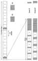
도 1 은 하향링크 무선 프레임의 구조를 설명하기 위한 도면이다.
도 2는 하나의 하향링크 슬롯에 대한 자원 그리드(resource grid)의 일례를 나타낸 예시도이다.
도 3은 하향링크 서브프레임의 구조를 나타내는 도면이다.
도 4는 상향링크 서브프레임의 구조를 나타내는 도면이다.
도 5 및 도 6 은 하향링크 제어채널들이 할당되는 단위인 자원요소그룹(REG)을 설명하는 도면이다.
도 7 은 물리제어포맷지시자채널(PCFICH)이 전송되는 방식을 나타내는 도면이다.
도 8 은 PCFICH 및 물리HARQ지시자채널(PHICH )의 위치를 나타내는 도면이다.
도 9 는 PHICH 그룹이 매핑되는 하향링크 자원요소 위치를 나타내는 도면이다.
도 10은 각 집합레벨에서의 탐색공간을 설명하기 위한 도면이다.
도 11은 셀 특정 참조신호를 설명하기 위한 도면이다.
도 12은 셀 탐색(cell search)에 사용되는 동기신호를 설명하기 위한 도면이다.
도 13은 PBCH(Physical Broadcast Channel)를 설명하기 위한 도면이다.
도 14는 동기신호 및 PBCH의 전송 타이밍을 나타내는 도면이다.
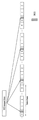
도 15 내지 도 16은 본 발명의 일 실시예에 의한 e-PDCCH 할당 방법 및 단말의 동작을 설명하기 위한 도면이다.
도 17은 본 발명에 따른 기지국 장치 및 단말 장치의 구성을 도시한 도면이다.1 is a view for explaining a structure of a downlink radio frame.
2 is an exemplary diagram illustrating an example of a resource grid for one downlink slot.
3 is a diagram showing a structure of a downlink sub-frame.
4 is a diagram illustrating the structure of an uplink subframe.
5 and 6 are views for explaining a resource element group REG, which is a unit in which downlink control channels are allocated.
7 is a diagram showing a manner in which a physical control format indicator channel (PCFICH) is transmitted.
8 is a diagram showing the positions of the PCFICH and the physical HARQ indicator channel (PHICH).
9 is a diagram illustrating a location of a downlink resource element to which a PHICH group is mapped.
10 is a diagram for explaining a search space at each set level.
11 is a diagram for explaining a cell specific reference signal.
12 is a diagram for explaining a synchronization signal used in a cell search.
13 is a diagram for explaining a PBCH (Physical Broadcast Channel).
Fig. 14 is a diagram showing the timing of transmission of the synchronizing signal and the PBCH. Fig.
15 to 16 are views for explaining an e-PDCCH allocation method and an operation of a UE according to an embodiment of the present invention.
17 is a diagram showing a configuration of a base station apparatus and a terminal apparatus according to the present invention.
이하의 실시예들은 본 발명의 구성요소들과 특징들을 소정 형태로 결합한 것들이다. 각 구성요소 또는 특징은 별도의 명시적 언급이 없는 한 선택적인 것으로 고려될 수 있다. 각 구성요소 또는 특징은 다른 구성요소나 특징과 결합되지 않은 형태로 실시될 수 있다. 또한, 일부 구성요소들 및/또는 특징들을 결합하여 본 발명의 실시예를 구성할 수도 있다. 본 발명의 실시예들에서 설명되는 동작들의 순서는 변경될 수 있다. 어느 실시예의 일부 구성이나 특징은 다른 실시예에 포함될 수 있고, 또는 다른 실시예의 대응하는 구성 또는 특징과 교체될 수 있다.The following embodiments are a combination of elements and features of the present invention in a predetermined form. Each component or characteristic may be considered optional unless otherwise expressly stated. Each component or feature may be implemented in a form that is not combined with other components or features. In addition, some of the elements and / or features may be combined to form an embodiment of the present invention. The order of the operations described in the embodiments of the present invention may be changed. Some configurations or features of certain embodiments may be included in other embodiments, or may be replaced with corresponding configurations or features of other embodiments.
본 명세서에서 본 발명의 실시예들을 기지국과 단말 간의 데이터 송신 및 수신의 관계를 중심으로 설명한다. 여기서, 기지국은 단말과 직접적으로 통신을 수행하는 네트워크의 종단 노드(terminal node)로서의 의미를 갖는다. 본 문서에서 기지국에 의해 수행되는 것으로 설명된 특정 동작은 경우에 따라서는 기지국의 상위 노드(upper node)에 의해 수행될 수도 있다.Embodiments of the present invention will be described herein with reference to the relationship between data transmission and reception between a base station and a terminal. Here, the BS has a meaning as a terminal node of a network that directly communicates with the MS. The particular operation described herein as performed by the base station may be performed by an upper node of the base station, as the case may be.
즉, 기지국을 포함하는 다수의 네트워크 노드들(network nodes)로 이루어지는 네트워크에서 단말과의 통신을 위해 수행되는 다양한 동작들은 기지국 또는 기지국 이외의 다른 네트워크 노드들에 의해 수행될 수 있음은 자명하다. '기지국(BS: Base Station)'은 고정국(fixed station), Node B, eNode B(eNB), 액세스 포인트(AP: Access Point) 등의 용어에 의해 대체될 수 있다. 릴레이는 RelayNode(RN), RelayStation(RS) 등의 용어에 의해 대체될 수 있다. 또한, '단말(Terminal)'은 UE(User Equipment), MS(Mobile Station), MSS(Mobile Subscriber Station), SS(Subscriber Station) 등의 용어로 대체될 수 있다.That is, it is apparent that various operations performed for communication with a terminal in a network composed of a plurality of network nodes including a base station can be performed by a network node other than the base station or the base station. A 'base station (BS)' may be replaced by a term such as a fixed station, a Node B, an eNode B (eNB), an access point (AP) Relays can be replaced by terms such as RelayNode (RN), RelayStation (RS), and so on. The term 'terminal' may be replaced with terms such as User Equipment (UE), Mobile Station (MS), Mobile Subscriber Station (MSS), and Subscriber Station (SS).
이하의 설명에서 사용되는 특정 용어들은 본 발명의 이해를 돕기 위해서 제공된 것이며, 이러한 특정 용어의 사용은 본 발명의 기술적 사상을 벗어나지 않는 범위에서 다른 형태로 변경될 수 있다.The specific terminology used in the following description is provided to aid understanding of the present invention, and the use of such specific terminology may be changed into other forms without departing from the technical idea of the present invention.
몇몇 경우, 본 발명의 개념이 모호해지는 것을 피하기 위하여 공지의 구조 및 장치는 생략되거나, 각 구조 및 장치의 핵심기능을 중심으로 한 블록도 형식으로 도시될 수 있다. 또한, 본 명세서 전체에서 동일한 구성요소에 대해서는 동일한 도면 부호를 사용하여 설명한다.In some instances, well-known structures and devices may be omitted or may be shown in block diagram form, centering on the core functionality of each structure and device, to avoid obscuring the concepts of the present invention. In the following description, the same components are denoted by the same reference numerals throughout the specification.
본 발명의 실시예들은 무선 접속 시스템들인 IEEE 802 시스템, 3GPP 시스템, 3GPP LTE 및 LTE-A(LTE-Advanced)시스템 및 3GPP2 시스템 중 적어도 하나에 개시된 표준 문서들에 의해 뒷받침될 수 있다. 즉, 본 발명의 실시예들 중 본 발명의 기술적 사상을 명확히 드러내기 위해 설명하지 않은 단계들 또는 부분들은 상기 문서들에 의해 뒷받침될 수 있다. 또한, 본 문서에서 개시하고 있는 모든 용어들은 상기 표준 문서에 의해 설명될 수 있다.Embodiments of the present invention may be supported by standard documents disclosed in at least one of the IEEE 802 systems, 3GPP systems, 3GPP LTE and LTE-Advanced (LTE-Advanced) systems, and 3GPP2 systems, which are wireless access systems. That is, the steps or portions of the embodiments of the present invention that are not described in order to clearly illustrate the technical idea of the present invention can be supported by the documents. In addition, all terms disclosed in this document may be described by the standard document.
이하의 기술은 CDMA(Code Division Multiple Access), FDMA(Frequency Division Multiple Access), TDMA(Time Division Multiple Access), OFDMA(Orthogonal Frequency Division Multiple Access), SC-FDMA(Single Carrier Frequency Division Multiple Access) 등과 같은 다양한 무선 접속 시스템에 사용될 수 있다. CDMA는 UTRA(Universal Terrestrial Radio Access)나 CDMA2000과 같은 무선 기술(radio technology)로 구현될 수 있다. TDMA는 GSM(Global System for Mobile communications)/GPRS(General Packet Radio Service)/EDGE(Enhanced Data Rates for GSM Evolution)와 같은 무선 기술로 구현될 수 있다. OFDMA는 IEEE 802.11 (Wi-Fi), IEEE 802.16 (WiMAX), IEEE 802-20, E-UTRA(Evolved UTRA) 등과 같은 무선 기술로 구현될 수 있다. UTRA는 UMTS(Universal Mobile Telecommunications System)의 일부이다. 3GPP(3rd Generation Partnership Project) LTE(long term evolution)는 E-UTRA를 사용하는 E-UMTS(Evolved UMTS)의 일부로써, 하향링크에서 OFDMA를 채용하고 상향링크에서 SC-FDMA를 채용한다. LTE-A(Advanced)는 3GPP LTE의 진화이다. WiMAX는 IEEE 802.16e 규격(WirelessMAN-OFDMA Reference System) 및 발전된 IEEE 802.16m 규격(WirelessMAN-OFDMA Advanced system)에 의하여 설명될 수 있다. 명확성을 위하여 이하에서는 3GPP LTE 및 3GPP LTE-A 시스템을 위주로 설명하지만 본 발명의 기술적 사상이 이에 제한되는 것은 아니다.The following description will be made on the assumption that the present invention is applicable to a CDMA system such as Code Division Multiple Access (CDMA), Frequency Division Multiple Access (FDMA), Time Division Multiple Access (TDMA), Orthogonal Frequency Division Multiple Access (OFDMA), and Single Carrier Frequency Division Multiple Access And can be used in various wireless access systems. CDMA may be implemented in radio technology such as Universal Terrestrial Radio Access (UTRA) or CDMA2000. The TDMA may be implemented in a wireless technology such as Global System for Mobile communications (GSM) / General Packet Radio Service (GPRS) / Enhanced Data Rates for GSM Evolution (EDGE). OFDMA may be implemented in wireless technologies such as IEEE 802.11 (Wi-Fi), IEEE 802.16 (WiMAX), IEEE 802-20, and Evolved UTRA (E-UTRA). UTRA is part of the Universal Mobile Telecommunications System (UMTS). 3GPP (3rd Generation Partnership Project) LTE (Long Term Evolution) is a part of E-UMTS (Evolved UMTS) using E-UTRA, adopting OFDMA in downlink and SC-FDMA in uplink. LTE-A (Advanced) is the evolution of 3GPP LTE. WiMAX can be described by the IEEE 802.16e standard (WirelessMAN-OFDMA Reference System) and the advanced IEEE 802.16m standard (WirelessMAN-OFDMA Advanced system). For the sake of clarity, the 3GPP LTE and 3GPP LTE-A systems will be described below, but the technical idea of the present invention is not limited thereto.
도 1은 3GPP LTE 시스템에서 사용되는 무선 프레임의 구조를 나타내는 도면이다. 도 1(a)를 참조하면 하나의 무선 프레임은 10 개의 서브프레임을 포함하고, 하나의 서브프레임은 시간 영역에서 2 개의 슬롯을 포함한다. 하나의 서브프레임을 전송하는 시간은 전송시간간격(Transmission Time Interval; TTI)으로 정의된다. 예를 들어, 하나의 서브프레임은 1ms의 길이를 가질 수 있고, 하나의 슬롯은 0.5ms의 길이를 가질 수 있다. 하나의 슬롯은 시간 영역에서 복수개의 OFDM 심볼들을 포함할 수 있다. 3GPP LTE 시스템은 하향링크에서 OFDMA 방식을 이용하므로, 상기 OFDM 심볼은 하나의 심볼 길이(period)를 나타낸다. 하나의 심볼은 상향링크에서 SC-FDMA 심볼 또는 심볼 길이로 칭하여질 수 있다. 자원블록(Resource Block; RB)은 자원 할당 단위로서, 하나의 슬롯에서 복수개의 연속하는 부반송파를 포함한다. 위와 같은 무선 프레임의 구조는 단지 예시적인 것이다. 따라서, 하나의 무선 프레임에 포함되는 서브프레임의 개수, 하나의 서브프레임에 포함되는 슬롯의 개수, 또는 하나의 슬롯에 포함되는 OFDM 심볼의 개수는 다양한 방식으로 변경될 수도 있다.1 is a diagram illustrating a structure of a radio frame used in a 3GPP LTE system. Referring to FIG. 1 (a), one radio frame includes 10 subframes, and one subframe includes two slots in the time domain. The transmission time of one subframe is defined as a transmission time interval (TTI). For example, one subframe may have a length of 1 ms, and one slot may have a length of 0.5 ms. One slot may comprise a plurality of OFDM symbols in the time domain. Since the 3GPP LTE system uses the OFDMA scheme in the downlink, the OFDM symbol represents one symbol period. One symbol may be referred to as an SC-FDMA symbol or a symbol length in the uplink. A resource block (RB) is a resource allocation unit, and includes a plurality of consecutive subcarriers in one slot. The structure of such a radio frame is merely exemplary. Therefore, the number of subframes included in one radio frame, the number of slots included in one subframe, or the number of OFDM symbols included in one slot may be changed in various manners.
도 1(b)는 타입 2 무선 프레임의 구조를 예시한다. 타입 2 무선 프레임은 2개의 하프 프레임(half frame)으로 구성된다. 각 하프 프레임은 5개의 서브프레임과 DwPTS(Downlink Pilot Time Slot), 보호구간(Guard Period, GP), UpPTS(Uplink Pilot Time Slot)로 구성되며, 이 중 1개의 서브프레임은 2개의 슬롯으로 구성된다. DwPTS는 단말에서의 초기 셀 탐색, 동기화 또는 채널 추정에 사용된다. UpPTS는 기지국에서의 채널 추정과 단말의 상향링크 전송 동기를 맞추는 데 사용된다. 보호구간은 상향링크와 하향링크 사이에 하향링크 신호의 다중경로 지연으로 인해 상향링크에서 생기는 간섭을 제거하기 위한 구간이다.Fig. 1 (b) illustrates the structure of a
여기서 무선 프레임의 구조는 예시에 불과하고, 무선 프레임에 포함되는 서브프레임의 수 또는 서브프레임에 포함되는 슬롯의 수, 슬롯에 포함되는 심볼의 수는 다양하게 변경될 수 있다.Here, the structure of the radio frame is merely an example, and the number of subframes included in a radio frame, the number of slots included in a subframe, and the number of symbols included in a slot can be variously changed.
도 2는 하향링크 슬롯에서의 자원 그리드(resource grid)를 나타내는 도면이다. 하나의 하향링크 슬롯은 시간 영역에서 7 개의 OFDM 심볼을 포함하고, 하나의 자원블록(RB)은 주파수 영역에서 12 개의 부반송파를 포함하는 것으로 도시되어 있지만, 본 발명이 이에 제한되는 것은 아니다. 예를 들어, 일반 CP(Cyclic Prefix)의 경우에는 하나의 슬롯이 7 OFDM 심볼을 포함하지만, 확장된 CP(extended-CP)의 경우에는 하나의 슬롯이 6 OFDM 심볼을 포함할 수 있다. 자원 그리드 상의 각각의 요소는 자원 요소(resource element)라 한다. 하나의 자원블록은 12×7 자원 요소를 포함한다. 하향링크 슬롯에 포함되는 자원블록들의 NDL의 개수는 하향링크 전송 대역폭에 따른다. 상향링크 슬롯의 구조는 하향링크 슬롯의 구조와 동일할 수 있다.2 is a diagram illustrating a resource grid in a downlink slot. One downlink slot includes seven OFDM symbols in the time domain, and one resource block (RB) includes 12 subcarriers in the frequency domain, but the present invention is not limited thereto. For example, one slot includes 7 OFDM symbols in the case of a normal CP (Cyclic Prefix), but one slot may include 6 OFDM symbols in an extended CP (CP). Each element on the resource grid is called a resource element. One resource block includes 12 x 7 resource elements. The number of NDLs of the resource blocks included in the downlink slot depends on the downlink transmission bandwidth. The structure of the uplink slot may be the same as the structure of the downlink slot.
도 3은 하향링크 서브프레임의 구조를 나타내는 도면이다. 하나의 서브프레임 내에서 첫 번째 슬롯의 앞 부분의 최대 3 개의 OFDM 심볼은 제어채널이 할당되는 제어 영역에 해당한다. 나머지 OFDM 심볼들은 물리하향링크공유채널(Physical Downlink Shared Chancel; PDSCH)이 할당되는 데이터 영역에 해당한다. 3GPP LTE 시스템에서 사용되는 하향링크 제어채널들에는, 예를 들어, 물리제어포맷지시자채널(Physical Control Format Indicator Channel; PCFICH), 물리하향링크제어채널(Physical Downlink Control Channel; PDCCH), 물리HARQ지시자채널(Physical Hybrid automatic repeat request Indicator Channel; PHICH) 등이 있다.3 is a diagram showing a structure of a downlink sub-frame. In a subframe, a maximum of three OFDM symbols in the first part of the first slot corresponds to a control area to which a control channel is allocated. The remaining OFDM symbols correspond to a data area to which a Physical Downlink Shared Chanel (PDSCH) is allocated. The downlink control channels used in the 3GPP LTE system include, for example, a Physical Control Format Indicator Channel (PCFICH), a Physical Downlink Control Channel (PDCCH), a Physical HARQ Indicator Channel (Physical Hybrid Automatic Repeat Request Indicator Channel (PHICH)).
PCFICH는 서브프레임의 첫 번째 OFDM 심볼에서 전송되고 서브프레임 내의 제어 채널 전송에 사용되는 OFDM 심볼의 개수에 대한 정보를 포함한다.The PCFICH includes information on the number of OFDM symbols transmitted in the first OFDM symbol of the subframe and used for control channel transmission in the subframe.
PHICH는 상향링크 전송의 응답으로서 HARQ ACK/NACK 신호를 포함한다.The PHICH includes an HARQ ACK / NACK signal as a response to the uplink transmission.
PDCCH를 통하여 전송되는 제어 정보를 하향링크제어정보(Downlink Control Information; DCI)라 한다. DCI는 상향링크 또는 하향링크 스케줄링 정보를 포함하거나 임의의 단말 그룹에 대한 상향링크 전송 전력 제어 명령을 포함한다. PDCCH는 하향링크공유채널(DL-SCH)의 자원 할당 및 전송 포맷, 상향링크공유채널(UL-SCH)의 자원 할당 정보, 페이징채널(PCH)의 페이징 정보, DL-SCH상의 시스템 정보, PDSCH상으로 전송되는 임의접속응답(RandomAccess Response)과 같은 상위계층 제어 메시지의 자원 할당, 임의의 단말 그룹 내의 개별 단말에 대한 전송 전력 제어 명령의 세트, 전송 전력 제어 정보, VoIP(Voice over IP)의 활성화 등을 포함할 수 있다. 복수의 PDCCH가 제어 영역 내에서 전송될 수 있다. 단말은 복수의 PDCCH를 모니터링할 수 있다. PDCCH는 하나 이상의 연속하는 제어채널요소(Control Channel Element; CCE)의 조합(aggregation)으로 전송된다. CCE는 무선 채널의 상태에 기초한 코딩 레이트로 PDCCH를 제공하기 위해 사용되는 논리 할당 단위이다. CCE는 복수개의 자원 요소 그룹에 대응한다. PDCCH의 포맷과 이용가능한 비트 수는 CCE의 개수와 CCE에 의해 제공되는 코딩 레이트 간의 상관관계에 따라서 결정된다. 기지국은 단말에게 전송되는 DCI에 따라서 PDCCH 포맷을 결정하고, 제어 정보에 순환잉여검사(Cyclic Redundancy Check; CRC)를 부가한다. CRC는 PDCCH의 소유자 또는 용도에 따라 무선 네트워크 임시 식별자(Radio Network Temporary Identifier; RNTI)라 하는 식별자로 마스킹된다. PDCCH가 특정 단말에 대한 것이면, 단말의 cell-RNTI(C-RNTI) 식별자가 CRC에 마스킹될 수 있다. 또는, PDCCH가 페이징 메시지에 대한 것이면, 페이징 지시자 식별자(Paging Indicator Identifier; P-RNTI)가 CRC에 마스킹될 수 있다. PDCCH가 시스템 정보(보다 구체적으로, 시스템 정보 블록(SIB))에 대한 것이면, 시스템 정보 식별자 및 시스템 정보 RNTI(SI-RNTI)가 CRC에 마스킹될 수 있다. 단말의 임의 접속 프리앰블의 전송에 대한 응답인 임의접속응답을 나타내기 위해, 임의접속-RNTI(RA-RNTI)가 CRC에 마스킹될 수 있다.The control information transmitted through the PDCCH is referred to as downlink control information (DCI). The DCI includes uplink or downlink scheduling information or includes an uplink transmission power control command for an arbitrary terminal group. The PDCCH includes a resource allocation and transmission format of a downlink shared channel (DL-SCH), resource allocation information of an uplink shared channel (UL-SCH), paging information of a paging channel (PCH), system information on a DL- A set of transmission power control commands for individual terminals in an arbitrary terminal group, transmission power control information, activation of Voice over IP (VoIP), and the like, for example, a resource allocation of an upper layer control message such as a random access response . ≪ / RTI > A plurality of PDCCHs may be transmitted within the control domain. The UE can monitor a plurality of PDCCHs. The PDCCH is transmitted in an aggregation of one or more contiguous Control Channel Elements (CCEs). The CCE is a logical allocation unit used to provide the PDCCH with a coding rate based on the state of the wireless channel. The CCE corresponds to a plurality of resource element groups. The format of the PDCCH and the number of available bits are determined according to the correlation between the number of CCEs and the coding rate provided by the CCE. The base station determines the PDCCH format according to the DCI transmitted to the UE and adds a cyclic redundancy check (CRC) to the control information. The CRC is masked with an identifier called a Radio Network Temporary Identifier (RNTI) according to the owner or use of the PDCCH. If the PDCCH is for a particular UE, the cell-RNTI (C-RNTI) identifier of the UE may be masked in the CRC. Alternatively, if the PDCCH is for a paging message, a Paging Indicator Identifier (P-RNTI) may be masked in the CRC. If the PDCCH is for system information (more specifically, the System Information Block (SIB)), the system information identifier and the system information RNTI (SI-RNTI) may be masked to the CRC. A random access-RNTI (RA-RNTI) may be masked to the CRC to indicate a random access response that is a response to the transmission of the UE's random access preamble.
도 4는 상향링크 서브프레임의 구조를 나타내는 도면이다. 상향링크 서브프레임은 주파수 영역에서 제어 영역과 데이터 영역으로 분할될 수 있다. 제어 영역에는 상향링크 제어 정보를 포함하는 물리상향링크제어채널(Physical Uplink Control Channel; PUCCH)이 할당된다. 데이터 영역에는 사용자 데이터를 포함하는 물리상향링크공유채널(Physical uplink shared channel; PUSCH)이 할당된다. 단일 반송파 특성을 유지하기 위해서, 하나의 단말은 PUCCH와 PUSCH를 동시에 전송하지 않는다. 하나의 단말에 대한 PUCCH는 서브프레임에서 자원블록 쌍(RB pair)에 할당된다. 자원블록 쌍에 속하는 자원블록들은 2 슬롯에 대하여 상이한 부반송파를 차지한다. 이를 PUCCH에 할당되는 자원블록 쌍이 슬롯 경계에서 주파수-호핑(frequency-hopped)된다고 한다.4 is a diagram illustrating the structure of an uplink subframe. The UL subframe may be divided into a control region and a data region in the frequency domain. A physical uplink control channel (PUCCH) including uplink control information is allocated to the control region. A physical uplink shared channel (PUSCH) including user data is allocated to the data area. To maintain a single carrier characteristic, one terminal does not transmit PUCCH and PUSCH at the same time. A PUCCH for one terminal is allocated to a resource block pair (RB pair) in a subframe. Resource blocks belonging to a resource block pair occupy different subcarriers for two slots. It is assumed that the resource block pair allocated to the PUCCH is frequency-hopped at the slot boundary.
DCIDCI 포맷 format
현재 LTE-A(release 10)에 의하면 DCI 포맷 0, 1, 1A, 1B, 1C, 1D, 2, 2A, 2B, 2C, 3, 3A, 4 가 정의되어 있다. 여기서 DCI 포맷 0, 1A, 3, 3A는, 후술할 블라인드 복호 횟수를 줄이기 위해 동일한 메시지 크기를 갖도록 규정되어 있다. 이러한 DCI 포맷들은 전송하려는 제어정보의 용도에 따라 i)상향링크 승인에 사용되는 DCI 포맷 0, 4, ii)하향링크 스케줄링 할당에 사용되는 DCI 포맷 1, 1A, 1B, 1C, 1D, 2, 2A, 2B, 2C, iii)전력제어 명령을 위한 DCI 포맷 3, 3A로 구분할 수 있다.According to LTE-A (release 10), DCI formats 0, 1, 1A, 1B, 1C, 1D, 2, 2A, 2B, 2C, 3, 3A and 4 are defined. Here, DCI formats 0, 1A, 3, and 3A are defined to have the same message size in order to reduce the number of blind decryption to be described later. These DCI formats may include
상향링크 승인에 사용되는 DCI 포맷 0의 경우, 후술할 반송파 병합에 관련하여 필요한 반송파 오프셋(carrier indicator), DCI 포맷 0과 1A를 구분하는데 사용되는 오프셋(flag for format 0/format 1A differentiation), 상향링크 PUSCH 전송에서 주파수 호핑이 사용되는지 여부를 알려주는 호핑 플래그(frequency hopping flag), 단말이 PUSCH 전송에 사용해야 할 자원블록 할당에 대한 정보(resource block assignment), 변조 및 부호화 방식(modulation and coding scheme), HARQ 프로세스와 관련해 초기전송을 위해 버퍼를 비우는데 사용되는 새 데이터 지시자(new data indicator), PUSCH를 위한 전송전력 제어명령(TPC command for scheduled for PUSCH), DMRS(Demodulation reference signal)를 위한 순환이동 정보(cyclic shift for DM RS and OCC index), TDD 동작에서 필요한 상향링크 인덱스(UL index) 및 채널품질정보(Channel Quality Indicator) 요구정보(CSI request) 등을 포함할 수 있다. 한편, DCI 포맷 0의 경우 동기식 HARQ를 사용하므로 하향링크 스케줄링 할당에 관련된 DCI 포맷들처럼 리던던시 버전(redundancy version)을 포함하지 않는다. 반송파 오프셋의 경우, 크로스 반송파 스케줄링이 사용되지 않는 경우에는 DCI 포맷에 포함되지 않는다.In the case of
DCI 포맷 4는 LTE-A 릴리즈 10에서 새로이 추가된 것으로서 LTE-A에서 상향링크 전송에 공간 다중화가 적용되는 것을 지원하기 위한 것이다. DCI 포맷 4의 경우 DCI 포맷 0과 비교하여 공간 다중화를 위한 정보들을 더 포함하므로 더 큰 메시지 크기를 가지며, DCI 포맷 0에 포함되는 제어정보에 추가적인 제어정보를 더 포함한다. 즉, DCI 포맷 4의 경우, 두 번째 전송블록을 위한 변조 및 부호화 방식, 다중 안테나 전송을 위한 프리코딩 정보, 사운딩참조신호 요청(SRS request) 정보를 더 포함한다. 한편, DCI 포맷 4는 DCI 포맷 0보다 큰 크기를 가지므로 DCI 포맷 0과 1A를 구분하는 오프셋은 포함하지 않는다.
하향링크 스케줄링 할당에 관련된 DCI 포맷 1, 1A, 1B, 1C, 1D, 2, 2A, 2B, 2C는 크게 공간 다중화를 지원하지 않는 1, 1A, 1B, 1C, 1D 와 공간 다중화를 지원하는 2, 2A, 2B, 2C 로 구분될 수 있다.DCI formats 1, 1A, 1B, 1C, 1D, 2, 2A, 2B and 2C related to downlink scheduling assignment are divided into 1, 1A, 1B, 1C and 1D, which do not support spatial multiplexing, 2A, 2B, and 2C.
DCI 포맷 1C는 컴팩트 하향링크 할당으로서 주파수 연속적 할당만을 지원하며, 다른 포맷들과 비교해 반송파 오프셋, 리던던시 버전을 포함하지 않는다.DCI format 1C only supports frequency sequential assignment as a compact downlink assignment, and does not include carrier offset, redundancy versions compared to other formats.
DCI 포맷 1A는 하향링크 스케줄링 및 랜덤 액세스 절차를 위한 포맷이다. 여기에는 반송파 오프셋, 하향링크 분산형 전송이 사용되는지 여부를 알려주는 표시자, PDSCH 자원 할당 정보, 변조 및 부호화 방식, 리던던시 버전, 소프트 컴바이닝을 위해 사용되는 프로세서를 알려주기 위한 HARQ 프로세서 번호, HARQ 프로세스와 관련해 초기전송을 위해 버퍼를 비우는데 사용되는 새 데이터 오프셋, PUCCH를 위한 전송전력 제어명령, TDD 동작에서 필요한 상향링크 인덱스 등을 포함할 수 있다.DCI format 1A is a format for downlink scheduling and random access procedures. An HARQ processor number for informing a processor used for soft combining, a HARQ processor number for informing a processor used for soft combining, a HARQ processor number for informing a processor used for soft combining, A new data offset used to empty the buffer for initial transmission in relation to the process, a transmit power control command for the PUCCH, an uplink index required for TDD operation, and the like.
DCI 포맷 1의 경우 대부분의 제어정보가 DCI 포맷 1A과 유사하다. 다만, DCI 포맷 1A가 연속적인 자원 할당에 관련된 것과 비교해, DCI 포맷 1은 비연속적 자원 할당을 지원한다. 따라서 DCI 포맷 1은 자원할당 헤더를 더 포함하므로 자원할당의 유연성이 증가하는 것의 트레이드 오프로서 제어 시그널링 오버헤드는 다소 증가한다.For
DCI 포맷 1B, 1D의 경우에는 DCI 포맷 1과 비교해 프리코딩 정보를 더 포함하는 점에서 공통된다. DCI 포맷 1B는 PMI 확인을, DCI 포맷 1D는 하향링크 전력 오프셋 정보를 각각 포함한다. 그 외 DCI 포맷 1B, 1D에 포함된 제어정보는 DCI 포맷 1A의 경우와 대부분 일치한다.In the case of DCI formats 1B and 1D, they are common in that they further include precoding information as compared with
DCI 포맷 2, 2A, 2B, 2C는 기본적으로 DCI 포맷 1A에 포함된 제어정보들을 대부분 포함하면서, 공간 다중화를 위한 정보들을 더 포함한다. 여기에는 두번째 전송 블록에 관한 변조 및 부호화 방식, 새 데이터 오프셋 및 리던던시 버전이 해당된다.The DCI formats 2, 2A, 2B, and 2C basically include most of the control information included in the DCI format 1A, and further include information for spatial multiplexing. This includes modulation and coding schemes, new data offsets and redundancy versions for the second transport block.
DCI 포맷 2는 폐루프 공간 다중화를 지원하며, 2A는 개루프 공간 다중화를 지원한다. 양자 모두 프리코딩 정보를 포함한다. DCI 포맷 2B는 빔 포밍과 결합된 듀얼 레이어 공간 다중화를 지원하며 DMRS를 위한 순환이동 정보를 더 포함한다. DCI 포맷 2C는 DCI 포맷 2B의 확장으로 이해될 수 있으며 여덟개의 레이어까지 공공간 다중화를 지원한다.
DCI 포맷 3, 3A는 전술한 상향링크 승인 및 하향링크 스케줄링 할당을 위한 DCI 포맷들에 포함되어 있는 전송전력 제어 정보를 보완, 즉 반-지속적(semi-persistent) 스케줄링을 지원하기 위해 사용될 수 있다. DCI 포맷 3의 경우 단말당 1bit, 3A의 경우 2bit의 명령이 사용된다.The DCI formats 3 and 3A may be used to supplement the transmission power control information included in the DCI formats for the uplink grant and the downlink scheduling assignment described above, i.e., to support semi-persistent scheduling. In case of
상술한 바와 같은 DCI 포맷 중 어느 하나는 하나의 PDCCH를 통해 전송되며, 복수의 PDCCH가 제어 영역 내에서 전송될 수 있다. 단말은 복수의 PDCCH를 모니터링 할 수 있다.Any one of the DCI formats as described above is transmitted on one PDCCH, and a plurality of PDCCHs can be transmitted in the control domain. The UE can monitor a plurality of PDCCHs.
하향링크 제어채널의 구성Configuration of downlink control channel
하향링크 제어채널이 전송되는 영역으로 기본적으로는 각각의 서브프레임의 처음 3개의 OFDM 심볼이 사용될 수 있으며, 하향링크 제어채널의 오버헤드에 따라서 1 내지 3개의 OFDM 심볼이 사용될 수 있다. 하향링크 제어채널을 위한 OFDM 심볼의 개수를 각 서브프레임마다 조정하기 위하여, PCFICH가 사용될 수 있다. 상향링크 전송에 대한 확인응답(긍정확인응답(ACK)/부정확인응답(NACK))을 하향링크를 통하여 제공하기 위하여 PHICH가 사용될 수 있다. 또한, 하향링크 데이터전송 또는 상향링크의 데이터전송을 위한 제어정보의 전송을 위해서 PDCCH 가 사용될 수 있다.The first three OFDM symbols of each subframe may be used as the transmission area of the downlink control channel, and one to three OFDM symbols may be used according to the overhead of the downlink control channel. In order to adjust the number of OFDM symbols for the downlink control channel for each subframe, a PCFICH may be used. The PHICH may be used to provide an acknowledgment (positive acknowledgment (ACK) / negative acknowledgment (NACK)) for the uplink transmission on the downlink. In addition, a PDCCH can be used for transmission of control information for downlink data transmission or uplink data transmission.
도 5 및 도 6 은 위와 같은 하향링크 제어채널들이 각각의 서브프레임의 제어 영역에서 자원요소그룹(Resource Element Group; REG) 단위로 할당되는 것을 나타낸다. 도 5 은 1 개 또는 2 개의 전송 안테나 구성을 가지는 시스템에 대한 것이고, 도 6 은 4 개의 전송 안테나 구성을 가지는 시스템에 대한 것이다. 도 5 및 도 6 에서 도시하는 바와 같이, 제어채널이 할당되는 기본적인 자원단위인 REG 는, 참조신호가 할당되는 자원요소를 제외하고 주파수 영역에서 연접한 4개의 RE 로 구성된다. 하향링크 제어채널의 오버헤드에 따라서 특정 개수의 REG 가 하향링크 제어채널의 전송에 이용될 수 있다.5 and 6 show that the DL control channels are allocated in units of Resource Element Groups (REG) in the control regions of the respective subframes. FIG. 5 is for a system with one or two transmit antenna configurations, and FIG. 6 is for a system with four transmit antenna configurations. As shown in FIGS. 5 and 6, the REG, which is a basic resource unit to which the control channel is allocated, is composed of four REs concatenated in the frequency domain except for the resource element to which the reference signal is allocated. Depending on the overhead of the downlink control channel, a certain number of REGs may be used for transmission of the downlink control channel.
PCFICHPCFICH ( ( PhysicalPhysical ControlControl FormatFormat IndicatorIndicator ChannelChannel ))
각각의 모든 서브프레임마다 해당 서브프레임의 자원 할당 정보 등을 제공하기 위해서 PDCCH 가 OFDM 심볼 인덱스 0 내지 2 사이에서 전송될 수 있고, 제어채널의 오버헤드에 따라서 OFDM 심볼 인덱스 0 이 사용되거나, OFDM 심볼 인덱스 0 및 1이 사용되거나, OFDM 심볼 인덱스 0 내지 2 가 사용될 수 있다. 이와 같이 제어채널이 사용하는 OFDM 심볼의 개수를 서브프레임마다 변경 할 수 있는데, 이에 대한 정보는 PCFICH를 통해 제공될 수 있다. 따라서, PCFICH는 각각의 모든 서브프레임에서 전송되어야 한다.A PDCCH may be transmitted between
PCFICH를 통해 3가지의 정보가 제공될 수 있다. 아래의 표 1 은 PCFICH의 CFI(Control Format Indicator)를 나타낸다. CFI=1 은 OFDM 심볼 인덱스 0 에서 PDCCH가 전송됨을 나타내고, CFI=2 는 OFDM 심볼 인덱스 0 및 1 에서 PDCCH가 전송됨을 나타내고, CFI=3 은 OFDM 심볼 인덱스 0 내지 2 에서 PDCCH가 전송됨을 나타낸다.Three kinds of information can be provided through PCFICH. Table 1 below shows CFI (Control Format Indicator) of PCFICH. CFI = 1 indicates that the PDCCH is transmitted at the

PCFICH 를 통해 전송되는 정보는 시스템 대역폭(system bandwidth)에 따라 다르게 정의될 수 있다. 예를 들면, 시스템의 대역폭이 특정 임계치보다 작은 경우 CFI=1, 2, 3 은 각각 2, 3, 4 개의 OFDM 심볼이 PDCCH를 위해 사용됨을 나타낼 수도 있다.Information transmitted through the PCFICH may be defined differently depending on the system bandwidth. For example, if the bandwidth of the system is below a certain threshold, CFI = 1, 2, 3 may indicate that 2, 3, or 4 OFDM symbols are used for the PDCCH, respectively.
도 7 은 PCFICH가 전송되는 방식을 나타내는 도면이다. 도 7 에서 도시하는 REG 는, 4개의 부반송파로 구성되어 있고, RS(참조신호)를 제외한 데이터 부반송파로만 구성되어 있으며, 일반적으로 전송 다이버시티(transmit diversity) 기법이 적용될 수 있다. 또한 REG의 위치는, 셀간에 간섭을 주지 않도록 셀마다 (즉, 셀 식별자에 따라서) 주파수 시프트될 수 있다. 추가적으로, PCFICH는 항상 서브프레임의 첫 번째 OFDM 심볼(OFDM 심볼 인덱스 0)에서 전송된다. 이에 따라 수신단에서는 서브프레임을 수신할 때에 먼저 PCFICH의 정보를 확인하여 PDCCH 가 전송되는 OFDM 심볼의 개수를 파악하고 그에 따라서 PDCCH를 통해 전송되는 제어 정보를 수신할 수 있다.7 is a diagram showing a manner in which the PCFICH is transmitted. The REG shown in FIG. 7 is composed of four subcarriers, and is composed only of data subcarriers except RS (reference signal), and a transmit diversity technique can be generally applied. Also, the position of the REG may be frequency-shifted per cell (i.e., depending on the cell identifier) so as not to interfere with the cells. In addition, the PCFICH is always transmitted in the first OFDM symbol (OFDM symbol index 0) of the subframe. Accordingly, the receiver can check the information of the PCFICH to receive the control information transmitted through the PDCCH according to the number of the OFDM symbols to which the PDCCH is transmitted.
PHICHPHICH ( ( PhysicalPhysical HybridHybrid -- ARQARQ IndicatorIndicator ChannelChannel ))
도 8 은 특정 대역폭에서 일반적으로 적용되는 PCFICH 및 PHICH 채널의 위치를 나타내는 도면이다. PHICH 를 통해서 상향링크 데이터 전송에 대한 ACK/NACK 정보가 전송된다. 하나의 서브프레임에서 여러 개의 PHICH 그룹이 만들어지고, 하나의 PHICH 그룹에는 여러 개의 PHICH가 존재한다. 따라서, 하나의 PHICH 그룹에는 여러 개의 단말에 대한 PHICH 채널이 포함된다.8 is a diagram showing locations of PCFICH and PHICH channels generally applied in a specific bandwidth. ACK / NACK information for uplink data transmission is transmitted through the PHICH. A plurality of PHICH groups are created in one subframe, and a plurality of PHICHs are present in one PHICH group. Therefore, one PHICH group includes PHICH channels for a plurality of terminals.
도 8 에서 도시하는 바와 같이, 여러 개의 PHICH 그룹에서 각 단말기에 대한 PHICH 할당은, PUSCH 자원 할당(resource allocation)의 가장 낮은 물리자원블록(Physical Resource Block; PRB) 인덱스(lowest PRB index)와, 상향링크 승인(grant) PDCCH 를 통해 전송되는 복조참조신호(Demodulation RS; DMRS)를 위한 순환시프트(Cyclic Shift) 인덱스를 이용하여 이루어진다. DMRS 는 상향링크 참조신호이며, 상향링크 데이터의 복조를 위한 채널 추정을 위해서 상향링크 전송과 함께 제공되는 신호이다. 또한, PHICH 자원은 ![]()
![]()
![]()
![]()
![]()
![]()
![]()
![]()
![]()
![]()
![]()
![]()

상기 수학식 1 에서 n DMRS 는 PHICH 가 연관된 상향링크 전송에서 사용된 DMRS 에 적용되는 순환시프트이며, 해당 PUSCH 전송과 연관된 전송블록(TB)에 대한 가장 최근의 상향링크 승인 제어 정보(예를 들어, DCI 포맷 0 또는 4)의 'cyclic shift for DMRS' 필드의 값에 매핑된다. 예를 들어, 가장 최근의 상향링크 승인 DCI 포맷의 'cyclic shift for DMRS' 필드는 3 비트 크기를 가질 수 있고, 이 필드가 '000'값을 가지면 n DMRS 는 '0' 값을 가지도록 설정될 수 있다.In the above equation (1), n DMRS Is a cyclic shift applied to the DMRS used in the uplink transmission in which the PHICH is associated and indicates the most recent uplink grant control information (e.g.,
상기 수학식 1 에서 ![]()
![]()
![]()
![]()
![]()
![]()

상기 수학식 2 에서 N g 는 물리방송채널(Physical Broadcast Channel; PBCH)로 전송되는 PHICH 자원의 양에 대한 정보이며, N g 는 2 비트 크기를 가지고 ( N g ∈ {1/6,1/2,1,2} )으로 표현된다. 상기 수학식 2 에서 ![]()
![]()
또한, 기존의 3GPP LTE 릴리즈-8/9 에서 정의되는 직교 시퀀스의 예는 아래의 표 2 와 같다.An example of the orthogonal sequence defined in the existing 3GPP LTE Release-8/9 is shown in Table 2 below.

도 9 는 PHICH 그룹이 매핑되는 하향링크 자원요소 위치를 나타내는 도면이다. PHICH 그룹은 PHICH 구간(duration)에 따라서 도 9 와 같이 하나의 서브프레임 내에서 상이한 시간 영역 (즉, 상이한 OS(OFDM Symbol)) 상에서 구성될 수도 있다.9 is a diagram illustrating a location of a downlink resource element to which a PHICH group is mapped. The PHICH group may be configured in different time domains (i.e., different OFDM symbols) within one subframe as shown in FIG. 9 depending on the PHICH duration.
PDCCHPDCCH 프로세싱 Processing
PDCCH를 RE들에 매핑할 때 연속된 논리할당단위인 제어채널요소(CCE)가 사용된다. 하나의 CCE는 복수(예를 들어, 9개)의 자원요소그룹(REG)을 포함하고, 하나의 REG는 참조 신호(RS)를 제외한 상태에서 이웃하는 네 개의 RE로 구성된다.When mapping the PDCCH to the REs, a control channel element (CCE) which is a consecutive logical allocation unit is used. One CCE includes a plurality of (e.g., nine) resource element groups (REG), and one REG is composed of four neighboring REs excluding the reference signal RS.
특정한 PDCCH를 위해 필요한 CCE의 개수는 제어정보의 크기인 DCI 페이로드, 셀 대역폭, 채널 부호화율 등에 따라 달라진다. 구체적으로 특정한 PDCCH를 위한 CCE의 개수는 다음 표 3과 같이 PDCCH 포맷에 따라 정의될 수 있다.The number of CCEs required for a particular PDCCH depends on the DCI payload, the cell bandwidth, the channel coding rate, etc., which is the size of the control information. Specifically, the number of CCEs for a specific PDCCH can be defined according to the PDCCH format as shown in Table 3 below.

PDCCH는 앞서 설명된 바와 같이 네가지 포맷 중 어느 하나의 포맷이 사용될 수 있는데, 이는 단말에게 알려지지 않는다. 따라서 단말의 입장에서는 PDCCH 포맷을 알지 못한 채 복호를 하여야 하는데, 이를 블라인드 복호라 한다. 다만, 단말이 하향링크에 사용되는 가능한 모든 CCE를 각 PDCCH 포맷에 대하여 복호하는 것은 큰 부담이 되므로, 스케줄러에 대한 제약과 복호 시도 횟수를 고려하여 탐색공간(Search Space)이 정의된다.The PDCCH can use any one of the four formats as described above, which is unknown to the UE. Therefore, the UE must decode the PDCCH without knowing the PDCCH format. This is called blind decoding. However, it is a great burden to the UE to decode all possible CCEs used in the downlink for each PDCCH format. Therefore, a search space is defined in consideration of the constraints on the scheduler and the number of decoding attempts.
즉, 탐색공간은 집합레벨(Aggregation Level) 상에서 단말이 복호를 시도해야 하는 CCE들로 이루어진 후보 PDCCH의 집합이다. 여기서 집합레벨 및 PDCCH 후보의 수는 다음 표 4와 같이 정의될 수 있다.That is, the search space is a set of candidate PDCCHs, which are composed of CCEs to which the UE should attempt to decode at an aggregation level. Here, the aggregation level and the number of PDCCH candidates can be defined as shown in Table 4 below.

상기 표 4에서 알 수 있듯이 4가지의 집합레벨이 존재하므로, 단말은 각 집합레벨에 따라 복수개의 탐색공간을 갖게 된다. 또한, 표 4에서 나타내는 바와 같이 탐색공간은 단말 특정 탐색공간과 공통 탐색공간으로 구분될 수 있다. 단말 특정 탐색공간은 특정한 단말들을 위한 것으로서 각 단말은 단말 특정 탐색공간을 모니터링(가능한 DCI 포맷에 따라 PDCCH 후보 집합에 대해 복호를 시도하는 것)하여 PDCCH에 마스킹되어 있는 RNTI 및 CRC를 확인하여 유효하면 제어정보를 획득할 수 있다.As shown in Table 4, since there are four aggregation levels, the UE has a plurality of search spaces according to each aggregation level. In addition, as shown in Table 4, the search space can be divided into a UE-specific search space and a common search space. The UE-specific search space is for specific UEs. Each UE monitors the UE-specific search space (attempts to decode the PDCCH candidate set according to the possible DCI format) to check the RNTI and CRC masked in the PDCCH Control information can be obtained.
공통 탐색공간은 시스템 정보에 대한 동적 스케줄링이나 페이징 메시지 등 복수개의 단말 또는 모든 단말들이 PDCCH를 수신해야 할 필요가 있는 경우를 위한 것이다. 다만, 공통 탐색공간은 자원 운용상 특정 단말을 위한 것으로 사용될 수도 있다. 또한, 공통 탐색공간은 단말 특정 탐색공간과 오버랩될 수도 있다.The common search space is for a case where a plurality of terminals or all terminals, such as dynamic scheduling or paging message for system information, need to receive a PDCCH. However, the common search space may be used for a specific terminal in resource operation. Further, the common search space may overlap with the UE-specific search space.
상기 탐색공간은 구체적으로 다음과 같은 수학식 3에 의해 결정될 수 있다.Specifically, the search space can be determined by the following equation (3).
![]()
![]()
여기서, L 은 집합레벨, Y k 는 RNTI 및 서브프레임 번호 k에 의해 결정되는 변수, m' 는 PDCCH 후보 수로서 반송파 병합이 적용된 경우 m'=m+M (L)·n CI 로, 그렇지 않은 경우 m'=m 로서 m=0,…,M (L)-1 이며 M (L) 은 PDCCH 후보 수, N CCE ,k 는 k번째 서브프레임에서 제어영역의 전체 CCE 개수, i 는 PDCCH 에서 각 PDCCH 후보에서 개별 CCE를 지정하는 인자로서 i=0,…,L-1 이다. 공통 탐색공간의 경우 Y k 는 항상 0으로 결정된다.Where L is the set level, Y k Is, if a number of PDCCH candidates are carrier merge applied m 'variable, m, which is determined by the RNTI and the sub-frame number k = m + M (L) · a n CI, otherwise m' = m as m = 0 , ... , M (L) -1, M (L) is the number of PDCCH candidates, N CCE , k is the total number of CCEs in the control region in the kth subframe, i is a factor specifying individual CCEs in each PDCCH candidate in the PDCCH, i = 0, ... , L -1. For the common search space Y k Is always set to zero.
도 10은 상기 수학식 3에 따라 정의될 수 있는 각 집합레벨에서의 단말 특정 탐색공간(음영부분)을 나타낸다. 여기서 반송파 병합은 사용되지 않았으며 N CCE ,k 는 설명의 편의를 위해 32개로 예시되었음을 밝혀둔다.FIG. 10 shows a terminal specific search space (shaded portion) at each set level that can be defined according to Equation (3) above. It is noted here that carrier merging is not used and N CCE , k is illustrated as 32 for convenience of explanation.
도 10의 (a), (b), (c), (d)는 각각 집합레벨 1, 2, 4, 8의 경우를 예시하며 숫자는 CCE 번호를 나타낸다. 도 10에서 각 집합레벨에서 탐색공간의 시작 CCE는 상술한 바와 같이 RNTI 및 서브프레임 번호 k로 결정되는데 하나의 단말에 대해 같은 서브프레임 내에서 모듈로 함수와 L 로 인해 집합레벨마다 서로 다르게 결정될 수 있으며 L 로 인해 항상 집합 레벨의 배수로만 결정된다. 여기서 Y k 는 예시적으로 CCE 번호 18로 전제되었다. 시작 CCE부터 단말은 해당 집합레벨에 따라 결정되는 CCE들 단위로 순차적으로 복호를 시도하게 된다. 예를 들어, 도 10의 (b)에서 단말은 시작 CCE인 CCE 번호 4부터 집합레벨에 따라 2개의 CCE 단위로 복호를 시도한다.10 (a), 10 (b), 10 (c) and 10 (d) illustrate the case of the
상술한 바와 같이 단말은 탐색공간에 대해 복호를 시도하는데, 이 복호시도의 횟수는 DCI 포맷 및 RRC 시그널링을 통해 결정되는 전송모드(Transmission mode)로 결정된다. 반송파 병합이 적용되지 않는 경우, 단말은 공통탐색공간에 대해 PDCCH 후보 수 6개 각각에 대해 두 가지의 DCI 크기(DCI 포맷 0/1A/3/3A 및 DCI 포맷 1C)를 고려하여야 하므로 최대 12번의 복호 시도가 필요하다. 단말 특정 탐색공간에 대해서는, PDCCH 후보 수(6 + 6 + 2 + 2 = 16) 에 대해 두 가지의 DCI 크기를 고려하므로 최대 32번의 복호 시도가 필요하다. 따라서 반송파 병합이 적용되지 않는 경우 최대 44회의 복호 시도가 필요하다.As described above, the UE attempts to decode the search space, and the number of the decoding attempts is determined as a transmission mode determined through DCI format and RRC signaling. If carrier combination is not applied, the terminal must consider two DCI sizes (
한편, 반송파 병합이 적용되는 경우 하향링크 자원(구성 반송파) 수만큼의 단말 특정 탐색공간과 DCI 포맷 4를 위한 복호가 더 추가되므로, 최대 복호횟수는 더 증가하게 된다.On the other hand, when carrier combination is applied, since the number of UE-specific search spaces corresponding to the number of downlink resources (constituent carriers) and the
참조신호 (The reference signal ( ReferenceReference SignalSignal , , RSRS ))
무선 통신 시스템에서 패킷을 전송할 때, 전송되는 패킷은 무선 채널을 통해서 전송되기 때문에 전송과정에서 신호의 왜곡이 발생할 수 있다. 왜곡된 신호를 수신측에서 올바로 수신하기 위해서는 채널 정보를 이용하여 수신 신호에서 왜곡을 보정하여야 한다. 채널 정보를 알아내기 위해서, 송신측과 수신측에서 모두 알고 있는 신호를 전송하여, 상기 신호가 채널을 통해 수신될 때의 왜곡 정도를 가지고 채널 정보를 알아내는 방법을 주로 사용한다. 상기 신호를 파일럿 신호(Pilot Signal) 또는 참조신호(Reference Signal)라고 한다.When a packet is transmitted in a wireless communication system, since the transmitted packet is transmitted through a wireless channel, signal distortion may occur in the transmission process. In order to properly receive the distorted signal at the receiving side, the distortion should be corrected in the received signal using the channel information. In order to determine the channel information, a method is used in which a signal known to both the transmitting side and the receiving side is transmitted, and channel information is detected with a degree of distortion when the signal is received through the channel. The signal is referred to as a pilot signal or a reference signal.
다중안테나를 사용하여 데이터를 송수신하는 경우에는 각 송신 안테나와 수신 안테나 사이의 채널 상황을 알아야 올바른 신호를 수신할 수 있다. 따라서, 각 송신 안테나 별로, 좀더 자세하게는 안테나 포트(port)별로 별도의 참조신호가 존재하여야 한다.When transmitting and receiving data using multiple antennas, it is necessary to know the channel condition between each transmitting antenna and the receiving antenna so that a correct signal can be received. Therefore, there is a separate reference signal for each transmission antenna, more specifically, for each antenna port.
참조신호는 상향링크 참조신호와 하향링크 참조신호로 구분될 수 있다. 현재 LTE 시스템에는 상향링크 참조신호로써,The reference signal may be divided into an uplink reference signal and a downlink reference signal. In the current LTE system, as an uplink reference signal,
i) PUSCH 및 PUCCH를 통해 전송된 정보의 코히런트(coherent)한 복조를 위한 채널 추정을 위한 복조 참조신호(DeModulation-Reference Signal, DM-RS)i) a demodulation reference signal (DM-RS) for channel estimation for coherent demodulation of information transmitted via PUSCH and PUCCH,
ii) 기지국이, 네트워크가 다른 주파수에서의 상향링크 채널 품질을 측정하기 위한 사운딩 참조신호(Sounding Reference Signal, SRS)가 있다.ii) The base station has a Sounding Reference Signal (SRS) for the network to measure the uplink channel quality at different frequencies.
한편, 하향링크 참조신호에는,On the other hand, in the downlink reference signal,
i) 셀 내의 모든 단말이 공유하는 셀-특정 참조신호(Cell-specific Reference Signal, CRS)i) a cell-specific reference signal (CRS) shared by all terminals in a cell,
ii) 특정 단말만을 위한 단말-특정 참조신호(UE-specific Reference Signal)ii) a UE-specific reference signal for a specific UE only;
iii) PDSCH가 전송되는 경우 코히런트한 복조를 위해 전송되는 (DeModulation-Reference Signal, DM-RS)iii) a DeModulation-Reference Signal (DM-RS) transmitted for coherent demodulation when the PDSCH is transmitted;
iv) 하향링크 DM-RS가 전송되는 경우 채널 상태 정보(Channel State Information; CSI)를 전달하기 위한 CSI-RS(Channel State Information-Reference Signal)iv) Channel State Information-Reference Signal (CSI-RS) for transmitting channel state information (CSI) when a downlink DM-RS is transmitted.
v) MBSFN(Multimedia Broadcast Single Frequency Network) 모드로 전송되는 신호에 대한 코히런트한 복조를 위해 전송되는 MBSFN 참조신호(MBSFN Reference Signal)v) MBSFN Reference Signal (MBSFN Reference Signal) transmitted for coherent demodulation on a signal transmitted in MBSFN (Multimedia Broadcast Single Frequency Network) mode,
vi) 단말의 지리적 위치 정보를 추정하는데 사용되는 위치 참조신호(Positioning Reference Signal)가 있다.vi) There is a positioning reference signal used to estimate the geographical location information of the terminal.
참조신호는 그 목적에 따라 크게 두 가지로 구분될 수 있다. 채널 정보 획득을 위한 목적의 참조신호와 데이터 복조를 위해 사용되는 참조신호가 있다. 전자는 UE가 하향 링크로의 채널 정보를 획득할 수 있는데 그 목적이 있으므로, 광대역으로 전송되어야 하고, 특정 서브 프레임에서 하향 링크 데이터를 수신하지 않는 단말이라도 그 참조신호를 수신하여야 한다. 또한 이는 핸드 오버 등의 상황에서도 사용된다. 후자는 기지국이 하향링크를 보낼 때 해당 리소스에 함께 보내는 참조신호로서, 단말은 해당 참조신호를 수신함으로써 채널 측정을 하여 데이터를 복조할 수 있게 된다. 이 참조신호는 데이터가 전송되는 영역에 전송되어야 한다.The reference signal can be roughly classified into two types according to its purpose. There are a target reference signal for channel information acquisition and a reference signal used for data demodulation. The former can acquire channel information on the downlink because the UE can acquire the channel information. Therefore, the former must receive the reference signal even if the terminal does not receive the downlink data in a specific subframe. It is also used in situations such as handover. The latter is a reference signal transmitted together with the resource when the base station transmits the downlink, and the terminal can demodulate the data by measuring the channel by receiving the reference signal. This reference signal should be transmitted in the area where data is transmitted.
CRS는 채널 정보 획득 및 데이터 복조의 두 가지 목적으로 사용되며, 단말 특정 참조신호는 데이터 복조용으로만 사용된다. CRS는 광대역에 대해서 매 서브프레임마다 전송되며, 기지국의 전송 안테나 개수에 따라서 최대 4개의 안테나 포트에 대한 참조신호가 전송된다.CRS is used for two purposes: channel information acquisition and data demodulation, and the UE-specific reference signal is used only for data demodulation. CRS is transmitted for each subframe for a wideband, and reference signals for up to four antenna ports are transmitted according to the number of transmission antennas of the base station.
예를 들어 기지국의 송신 안테나의 개수가 2개일 경우, 0번과 1번 안테나 포트에 대한 CRS가 전송되고, 4개인 경우 0~3번 안테나 포트에 대한 CRS가 각각 전송된다.For example, if the number of transmit antennas of the base station is two, the CRS is transmitted for the
도 11(a)에는 안테나 포트 0번에 대한 CRS의 한 RB내에서의 패턴이 도시되어 있고, 도 11(b)에는 기지국의 송신 안테나가 4개일 경우 한 RB에서의 CRS 패턴이 도시되어 있다. 도 11(a) 및 (b)를 참조하면, CRS가 시간-주파수 자원에 맵핑될 때에는, 주파수 축에서 하나의 안테나 포트에 대한 참조신호는 6 RE당 1개의 RE에 맵핑되어 전송된다. 하나의 RB가 주파수 상에서 12개의 RE로 구성되어 있으므로 하나의 안테나 포트에 대한 RE는 RB당 2개의 RE가 사용된다.FIG. 11A shows a pattern in one RB of the CRS for
CSICSI -- RSRS
다중 안테나 전송(Multi-Input Multi-Output, MIMO) 방식은 개-루프(open-loop) 방식과 폐-루프(closed-loop) 방식으로 구분될 수 있다. 개-루프 MIMO 방식은 MIMO 수신단으로부터의 채널상태정보의 피드백이 없이 송신단에서 MIMO 전송을 수행하는 것을 의미한다. 폐-루프 MIMO 방식은 MIMO 수신단으로부터의 채널상태정보를 피드백 받아 송신단에서 MIMO 전송을 수행하는 것을 의미한다. 폐-루프 MIMO 방식에서는 MIMO 송신 안테나의 다중화 이득(multiplexing gain)을 얻기 위해서 송신단과 수신단의 각각이 채널상태정보를 바탕으로 빔포밍을 수행할 수 있다. 수신단(예를 들어, 단말)이 채널상태정보를 피드백할 수 있도록 송신단(예를 들어, 기지국)은 수신단(예를 들어, 단말)에게 상향링크 제어 채널 또는 상향링크 공유 채널을 할당할 수 있다.A multi-input multi-output (MIMO) scheme can be divided into an open-loop scheme and a closed-loop scheme. The open-loop MIMO scheme means that the transmitter performs MIMO transmission without feedback of channel state information from the MIMO receiver. The closed-loop MIMO scheme means that MIMO transmission is performed at the transmitter by receiving feedback of channel state information from the MIMO receiver. In a closed-loop MIMO scheme, each of a transmitter and a receiver can perform beamforming based on channel state information to obtain a multiplexing gain of a MIMO transmit antenna. A transmitting end (for example, a base station) can allocate an uplink control channel or an uplink shared channel to a receiving end (for example, a terminal) so that a receiving end (for example, a terminal) can feed back channel status information.
피드백되는 채널상태정보(CSI)는 랭크 지시자(RI), 프리코딩 행렬 인덱스(PMI) 및 채널품질지시자(CQI)를 포함할 수 있다.The fed back channel state information (CSI) may include a rank indicator (RI), a precoding matrix index (PMI), and a channel quality indicator (CQI).
RI는 채널 랭크에 대한 정보이다. 채널의 랭크는 동일한 시간-주파수 자원을 통해서 서로 다른 정보를 보낼 수 있는 레이어(또는 스트림)의 최대 개수를 의미한다. 랭크 값은 채널의 장기간(long term) 페이딩에 의해서 주로 결정되므로, PMI 및 CQI 에 비하여 일반적으로 더 긴 주기에 따라 피드백될 수 있다.RI is information about the channel rank. The rank of a channel means the maximum number of layers (or streams) that can send different information through the same time-frequency resource. The rank value is mainly determined by the long term fading of the channel, so it can be fed back in a generally longer period than the PMI and CQI.
PMI는 송신단으로부터의 전송에 이용되는 프리코딩 행렬에 대한 정보이며, 채널의 공간 특성을 반영하는 값이다. 프리코딩이란 전송 레이어를 송신 안테나에 매핑시키는 것을 의미하며, 프리코딩 행렬에 의해 레이어-안테나 매핑 관계가 결정될 수 있다. PMI 는 신호대잡음및간섭비(Signal-to-Interference plus Noise Ratio; SINR) 등의 측정값(metric)을 기준으로 단말이 선호하는(preferred) 기지국의 프리코딩 행렬 인덱스에 해당한다. 프리코딩 정보의 피드백 오버헤드를 줄이기 위해서, 송신단과 수신단이 여러 가지 프리코딩 행렬을 포함하는 코드북을 미리 공유하고 있고, 해당 코드북에서 특정 프리코딩 행렬을 지시하는 인덱스만을 피드백하는 방식이 사용될 수 있다.The PMI is information on the precoding matrix used for transmission from the transmitting end and is a value reflecting the spatial characteristics of the channel. Precoding refers to mapping a transmission layer to a transmission antenna, and a layer-antenna mapping relationship can be determined by a precoding matrix. PMI corresponds to a precoding matrix index of a base station preferred by the UE based on a metric such as a Signal-to-Interference plus Noise Ratio (SINR). In order to reduce the feedback overhead of the precoding information, a scheme may be used in which a transmitting end and a receiving end share a codebook including various precoding matrices in advance and only an index indicating a specific precoding matrix is fed back in the corresponding codebook.
CQI는 채널 품질 또는 채널 세기를 나타내는 정보이다. CQI는 미리 결정된 MCS 조합으로서 표현될 수 있다. 즉, 피드백되는 CQI 인덱스는 해당하는 변조기법(modulation scheme) 및 코드 레이트(code rate)를 나타낸다. 일반적으로, CQI 는 기지국이 PMI 를 이용하여 공간 채널을 구성하는 경우에 얻을 수 있는 수신 SINR 을 반영하는 값이 된다.The CQI is information indicating channel quality or channel strength. The CQI may be expressed as a predetermined MCS combination. That is, the feedback CQI index indicates a corresponding modulation scheme and a code rate. Generally, the CQI is a value that reflects the reception SINR that can be obtained when a base station constructs a spatial channel using PMI.
PSSPSS (( PrimaryPrimary synchronoussynchronous signalsignal ) /SSS() / SSS ( SecondarySecondary SynchronousSynchronous SignalSignal ))
도 12는 LTE/LTE-A 시스템에서 셀 탐색(cell search)에 사용되는 동기신호인 PSS 및 SSS을 설명하기 위한 도면이다. PSS 및 SSS를 설명하기 앞서, 셀 탐색에 대해 살펴보면, 셀 탐색은 단말이 최초로 셀에 접속하는 경우, 현재 접속되어 있는 셀에서 다른 셀로 핸드오버 또는 셀 재선택을 하기 위해 수행하는 것으로써, 셀에 대한 주파수 및 심볼 동기 획득, 셀의 하향링크 프레임 동기 획득 및 셀 식별자(ID) 결정으로 이루어질 수 있다. 셀 식별자는 3개가 하나의 셀 그룹을 이루고, 셀 그룹은 168개가 존재할 수 있다.12 is a diagram for explaining PSS and SSS which are synchronization signals used for cell search in the LTE / LTE-A system. Before explaining the PSS and the SSS, the cell search is performed to perform handover or cell reselection from the currently connected cell to the other cell when the UE first accesses the cell, Acquisition of a frequency and symbol synchronization, acquisition of a downlink frame synchronization of a cell, and determination of a cell identifier (ID). Three cell identifiers may form one cell group, and 168 cell groups may exist.
셀 탐색을 위해 기지국에서는 PSS 및 SSS를 전송한다. 단말은 PSS를 검출하여 셀의 5ms 타이밍을 획득하고, 셀 그룹 내의 셀 식별자에 대해 알수 있다. 또한, 단말은 SSS를 검출하여 라디오 프레임 타이밍 및 셀 그룹을 알 수 있다.The base station transmits PSS and SSS for cell search. The terminal detects the PSS, acquires the 5 ms timing of the cell, and knows about the cell identifier in the cell group. Also, the UE detects the SSS to know the radio frame timing and the cell group.
도 12을 참조하면, PSS는 0번 및 5번 서브프레임에서 전송되며, 보다 상세하게는 0번 및 5번 서브프레임에서 첫 번째 슬롯의 마지막 OFDM 심볼에 전송된다. 또한, SSS는 0번 및 5번 서브프레임의 첫 번째 슬롯의 마지막에서 두 번째 OFDM 심볼에서 전송된다. 즉, SSS는 PSS가 전송되기 직전의 OFDM 심볼에서 전송된다. 이러한 전송 타이밍은 FDD의 경우이다.Referring to FIG. 12, the PSS is transmitted in the 0th and 5th subframes, more specifically, in the 0th and 5th subframes in the last OFDM symbol of the first slot. Also, the SSS is transmitted in the second OFDM symbol at the end of the first slot of the 0th and 5th subframes. That is, the SSS is transmitted in the OFDM symbol immediately before the PSS is transmitted. This transmission timing is in the case of FDD.
TDD의 경우(미도시) PSS는 1번 및 6번 서브프레임의 세 번째 심볼, 즉, DwPTS에서 전송되며, SSS는 0번 및 5번 서브프레임의 마지막 심볼에서 전송된다. 즉, TDD에서 SSS는 PSS보다 3심볼 앞에서 전송된다.In the case of TDD (not shown), the PSS is transmitted in the third symbol of the first and sixth subframes, i.e., the DwPTS, and the SSS is transmitted in the last symbols of the 0th and 5th subframes. That is, in TDD, SSS is transmitted before PSS by 3 symbols.
PSS는 길이 63의 자도프-추(Zadoff-Chu) 시퀀스이며, 실제 전송에 있어서는 시퀀스의 양쪽 끝에 0이 패딩되어 시퀀스가 시스템 주파수 대역폭의 가운데 73개의 부반송파(DC 부반송파를 제외하면 72개의 부반송파, 즉 6RB) 상으로 전송된다. SSS는 두 개의 길이 31인 시퀀스가 주파수 인터리빙된 길이 62의 시퀀스로 이루어지며, PSS와 마찬가지로 전체 시스템 대역폭의 가운데 72개의 부반송파 상에서 전송된다.PSS is a Zadoff-Chu sequence with a length of 63. In the actual transmission, 0 is padded at both ends of the sequence so that the sequence is divided into 73 subcarriers in the system frequency bandwidth (72 subcarriers excluding DC subcarriers, that is, 6RB. The SSS consists of a sequence of two 31 lengths interleaved with a length of 62 sequences and is transmitted on 72 subcarriers in the middle of the total system bandwidth as the PSS.
PBCH(PBCH ( PhysicalPhysical BroadcastBroadcast ChannelChannel ))
도 13은 PBCH를 설명하기 위한 도면이다. PBCH는 주정보블록(Master Information Block, MIB)가 전송되는 채널로써, 단말이 앞서 설명된 PSS/SSS를 통해 동기를 획득하고 셀 식별자를 획득한 이후 시스템 정보를 획득하는데 사용된다. 여기서 MIB에는 하향링크 셀 대역폭 정보, PHICH 설정 정보, 서브프레임 번호(System Frame Number, SFN) 등이 포함될 수 있다.13 is a diagram for explaining the PBCH. The PBCH is a channel through which a master information block (MIB) is transmitted. The PBCH is used to acquire system information after the UE obtains synchronization through the PSS / SSS described above and acquires the cell identifier. Here, the MIB may include downlink cell bandwidth information, PHICH setting information, a system frame number (SFN), and the like.
BCH는 도 13에 도시된 바와 같이, 하나의 BCH 전송 블록이 4개의 연속된 라디오 프레임에서 각각 첫 번째 서브프레임을 통하여 전송된다. 보다 상세히 설명하면, BCH는 4개의 연속된 라디오 프레임에서 0번 서브프레임의 두 번째 슬롯의 처음 4개의 OFDM 심볼에서 전송되며, 주파수 축에서 전체 대역폭의 가운데 72개의 부반송파상에서 전송된다. 이는 가장 작은 하향링크 대역폭인 6RB에 해당하는 것으로 단말이 전체 시스템 대역폭의 크기를 모르는 경우여도 문제없이 BCH를 디코딩 할 수 있도록 하기 위함이다.As shown in FIG. 13, one BCH transport block is transmitted through each first subframe in four consecutive radio frames. In more detail, the BCH is transmitted in the first four OFDM symbols of the second slot of the zero subframe in four consecutive radio frames, and is transmitted on the 72 subcarriers of the entire bandwidth in the frequency axis. This corresponds to 6 RB, which is the smallest downlink bandwidth, so that the BCH can be decoded without any problem even if the UE does not know the size of the entire system bandwidth.
상술한 PSS/SSS 및 PBCH의 전송 타이밍을 FDD의 경우에서 함께 살펴보면, 도 14와 같다. 도 14를 참조하면, 각 라디오 프레임에서, 0번 서브프레임의 첫 번째 슬롯의 마지막 두 OFDM 심볼에서 SSS 및 PSS가 전송되고 이어서 두 번째 슬롯의 처음 4개의 OFDM 심볼에서 PBCH가 전송된다. 또한, 5번 서브프레임의 첫 번째 슬롯의 마지막 두 OFDM 심볼에서 SSS 및 PSS가 각각 전송된다. PDCCH와의 관계에 있어서, PDCCH는 PCFICH에 의해 지시되는 제어영역(셀 대역폭에 따라, 각 서브프레임의 처음 1개 ~ 4개 OFDM 심볼)상에서 전송되므로, PSS/SSS 및 PBCH가 전송되는 자원영역과는 분리되어 있음을 알 수 있다. 또한, 앞서 언급된 CRS 및 CSI-RS가 전송되는 위치에서는 PDCCH가 전송되지 않는다. 다만, 현재 논의가 진행중인 e-PDCCH가 전송되는 경우 PSS/SSS 및 PBCH등과의 관계에 있어서 충돌이 발생할 수 있어 문제가 된다.The transmission timings of the PSS / SSS and the PBCH will be described together in the case of the FDD as shown in FIG. Referring to FIG. 14, in each radio frame, SSS and PSS are transmitted in the last two OFDM symbols of the first slot of the zero subframe, and PBCH is transmitted in the first four OFDM symbols of the second slot. In addition, SSS and PSS are transmitted in the last two OFDM symbols of the first slot of the fifth subframe. PDCCH, the PDCCH is transmitted on the control region (the first one to four OFDM symbols of each subframe according to the cell bandwidth) indicated by the PCFICH, so that the PSS / SSS and the resource region in which the PBCH is transmitted It can be seen that it is separated. In addition, the PDCCH is not transmitted at the position where the CRS and CSI-RS mentioned above are transmitted. However, when the e-PDCCH being currently under discussion is transmitted, a conflict may occur in the relationship with the PSS / SSS and the PBCH, which is a problem.
e-PDCCH에 대해 좀 더 알아보면, 현재 논의되고 있는 e-PDCCH는 기존 LTE/LTE-A 시스템에서 데이터 영역, 즉 PUSCH 전송에 사용되는 자원영역 상으로 PDCCH를 전송하는 개념이다. 이러한 e-PDCCH는 반송파 병합(Carrier Aggregation), 협력 멀티 포인트(Coordinated Multi Point, CoMP), MU-MIMO(Multi User Multiple-input-Multiple-output), MTC(Machine Type Communication), HetNet(Heterogeneous Network) 등에서의 기존 PDCCH의 용량한계, 셀 사이에서의 PDCCH간 및/또는 PDCCH와 PUSCH/PUCCH간의 간섭 문제 등이 도입 배경이다. e-PDCCH는 앞서 언급된 것과 같이 PDSCH 영역에서 전송될 수 있으며, DMRS(DeModulation Reference Signal)을 기반으로 할 수 있다. 즉, 단말이 e-PDCCH를 디코딩할 때 채널 추정을 DMRS를 이용할 수 있으며, 이를 위해 기지국은 e-PDCCH와 DMRS를 함께 프리코딩할 수 있다.The e-PDCCH, which is currently being discussed, is a concept of transmitting a PDCCH on a data area, that is, a resource area used for PUSCH transmission in an existing LTE / LTE-A system. The e-PDCCH may be a carrier aggregation, Coordinated Multi Point (CoMP), Multi User Multiple-Input Multiple-Output (MU-MIMO), Machine Type Communication (MTC), Heterogeneous Network And the interference problem between the PDCCH and the PUSCH / PUCCH between the PDCCH and the PDCCH between cells. The e-PDCCH may be transmitted in the PDSCH region as described above, and may be based on a DMRS (DeModulation Reference Signal). That is, when the UE decodes the e-PDCCH, the channel estimation can use the DMRS, and the base station can precode the e-PDCCH and the DMRS together.
즉, e-PDCCH는 PDSCH 영역에서 전송될 수 있으며, 이러한 경우 시스템을 위한 기본적인 정보들, PSS/SSS, PBCH, RS, CSI-RS 등이 전송되는 자원영역과 충돌이 발생할 수 있다.That is, the e-PDCCH can be transmitted in the PDSCH region. In this case, a collision may occur with a resource region where basic information for the system, PSS / SSS, PBCH, RS, CSI-RS,
따라서, 본 발명에서는 PSS, SSS, PBCH가 할당되는 대역, 즉 전체 주파수 대역에서 PSS, SSS 및/또는 PBCH가 전송되는 한가운데 6 RB에는 e-PDCCH가 할당/전송되지 않을 것(단말의 입장에서는 e-PDCCH가 전송되지 않는 것으로 기대하고 해당 영역에 대해 e-PDCCH 디코딩/블라인드 복호를 수행하지 않을 것)을 제안한다. 또한, 본 발명에서는 e-PDCCH가 전송될 때 PSS, SSS, PBCH가 전송되는 경우 e-PDCCH와 상기 신호들이 겹치는 RE에서는 e-PDCCH를 펑처링(puncturing)할 것을 제안한다. 또한, 본 발명에서는 e-PDCCH가 전송될 때 PSS, SSS, PBCH가 전송되는 경우 e-PDCCH와 상기 신호들이 겹치는 RE에서는 e-PDCCH를 전송하지 않으며 레이트 매칭(rate-matching)을 할 것을 제안한다.Therefore, in the present invention, it is assumed that an e-PDCCH is not allocated / transmitted to a 6 RB in which PSS, SSS and / or PBCH are transmitted in a band where PSS, SSS and PBCH are allocated, -PDCCH is not transmitted and e-PDCCH decoding / blind decoding is not performed for the corresponding region). Also, in the present invention, when PSS, SSS, and PBCH are transmitted when an e-PDCCH is transmitted, it is proposed to puncture an e-PDCCH in an e-PDCCH and an RE in which the signals overlap each other. Also, in the present invention, when PSS, SSS, and PBCH are transmitted when an e-PDCCH is transmitted, it is proposed to rate-match the e-PDCCH without transmitting an e-PDCCH in an RE where the signals overlap each other .
이하에서는 상술한 본 발명의 제안에 관한 구체적인 실시예들에 대해 설명한다. 이하의 설명에서, 특정 영역에서 e-PDCCH가 할당/전송되지 않는다고 함은, 단말의 측면에서는 특정 영역에서 e-PDCCH가 전송되지 않는 것으로 가정(assum)/기대(expect)하고 그 특정 영역을 제외한 자원 영역에서 e-PDCCH를 디코딩/블라인드 복호를 수행한다는 의미로 이해될 수 있다.Hereinafter, specific embodiments of the present invention will be described. In the following description, it is assumed that an e-PDCCH is not allocated / transmitted in a specific area. Assuming that an e-PDCCH is not transmitted in a specific area on the side of the UE, And performing decoding / blind decoding of the e-PDCCH in the resource region.
실시예Example 1 One
PSS/SSS 및/또는 PBCH가 전송되는 서브프레임에서 PSS/SSS 및/또는 PBCH가 전송되는 주파수 영역(전체 주파수 대역에서 한가운데 6RB)에서는 e-PDCCH가 할당/전송되지 않을 수 있다. 다시 말해, PSS/SSS 및/또는 PBCH가 전송되는 서브프레임에서는 PSS/SSS 및/또는 PBCH가 할당되는 PRB 페어(pair)에서는 e-PDCCH가 할당/전송되지 않을 수 있다. 즉, e-PDCCH가 할당되는 자원 영역은, 동기신호(PSS/SSS) 또는 PBCH의 전송에 사용되는 자원(전체 주파수 대역에서 한 가운데 6RB에 해당하는 PRB 페어)는 해당하지 않는 것이다.The e-PDCCH may not be allocated / transmitted in the frequency domain (6 RB in the middle in the entire frequency band) in which the PSS / SSS and / or the PBCH are transmitted in the PSS / SSS and / or the subframe in which the PBCH is transmitted. In other words, e-PDCCH may not be allocated / transmitted in a PRB pair to which PSS / SSS and / or PBCH are allocated in a subframe where PSS / SSS and / or PBCH are transmitted. That is, the resource area to which the e-PDCCH is allocated does not correspond to a resource (a PRB pair corresponding to 6 RBs in the entire frequency band) used for transmission of the synchronization signal (PSS / SSS) or PBCH.
상기 실시예를 특히 FDD의 경우에서 살펴보면 도 15와 같다. 도 15(a)는 PSS/SSS가 전송되는 5번 서브프레임을, 도 15(b)는 PSS/SSS 및 PBCH가 전송되는 0번 서브프레임을 나타낸다. 도 15(a)에서 PSS/SSS가 전송되는 주파수 영역(1510)에서는 e-PDCCH가 전송되지 않고, 또한 도 15(b)에서 PSS/SSS 및/또는 PBCH가 전송되는 주파수 영역(1520)에서도 e-PDCCH가 전송되지 않는 것을 알 수 있다.The above embodiment is particularly shown in FIG. 15 in the case of FDD. 15 (a) shows a fifth subframe in which the PSS / SSS is transmitted, and FIG. 15 (b) shows a zero subframe in which the PSS / SSS and the PBCH are transmitted. 15 (a), e-PDCCH is not transmitted in the
도시하지는 않았지만, TDD의 경우를 살펴보면, PSS가 전송되는 0번 및 5번 서브프레임과 SSS가 전송되는 1번 및 6번 서브프레임에서는 PSS/SSS 및/또는 PBCH가 전송되는 주파수 영역(전체 주파수 대역에서 한가운데 6RB)에는 e-PDCCH가 전송되지 않을 수 있다.Although not shown, in the TDD case, in the 0th and 5th subframes in which the PSS is transmitted and in the 1st and 6th subframes in which the SSS is transmitted, the frequency domain in which the PSS / SSS and / or the PBCH are transmitted 6RB in the middle), e-PDCCH may not be transmitted.
실시예Example 2 2
PSS/SSS는 FDD의 경우 첫 번째 슬롯에서만 전송되므로, PSS/SSS가 전송되는 서브프레임에서는 첫 번째 슬롯에는 e-PDCCH가 할당/전송되지 않고 두 번째 슬롯에는 e-PDCCH가 할당/전송되도록 할 수 있다. 그리고, PSS/SSS 및 PBCH가 모두 전송되는 서브프레임에서는 첫 번째 슬롯 및 두 번째 슬롯 모두 e-PDCCH가 할당/전송되지 않을 수 있다. 구체적으로, PSS/SSS가 전송되는 5번 서브프레임에서 첫 번째 슬롯의 한가운데 6RB에서는 e-PDCCH가 할당/전송되지 않고 두 번째 슬롯에서는 한 가운데 6RB에서도 e-PDCCH가 전송될 수 있다.Since the PSS / SSS is transmitted only in the first slot in the case of the FDD, in the subframe in which the PSS / SSS is transmitted, the e-PDCCH is not allocated / transmitted in the first slot and the e-PDCCH is allocated / have. In a subframe in which both the PSS / SSS and the PBCH are transmitted, the e-PDCCH may not be allocated / transmitted in both the first slot and the second slot. Specifically, the e-PDCCH is not allocated / transmitted in the 6RB in the center of the first slot in the 5th subframe where the PSS / SSS is transmitted, and the e-PDCCH can be transmitted in 6RB in the second slot.
그리고, PSS/SSS 및 PBCH가 전송되는 0번 서브프레임에서는 첫 번째 슬롯 및 두 번째 슬롯 모두에서 한가운데 6RB에서는 e-PDCCH가 할당/전송되지 않을 수 있다. 이는 도 16에 도시되어 있는데, 5번 서브프레임인 도 16(a)에서 첫 번째 슬롯의 한 가운데 6RB(1610) 및 0번 서브프레임인 도 16(b)에서 첫 번째 슬롯 및 두 번째 슬롯의 한 가운데 6 RB(1620)에는 e-PDCCH가 할당/전송되지 않는 것을 알 수 있다.In the 0th subframe in which the PSS / SSS and the PBCH are transmitted, the e-PDCCH may not be allocated / transmitted in the middle in both the first slot and the second slot and in 6RB. This is shown in FIG. 16. In FIG. 16 (a), the first slot and the second slot in FIG. 16 (a) are 6RB (1610) And the e-PDCCH is not allocated / transmitted to the 6
정리하면, 특정 서브프레임에서 PSS, SSS 및 PBCH의 전송 여부의 조합에 따라 단말이 e-PDCCH를 위해 디코딩을 수행하는 자원 영역이 달라질 수 있다. 즉, PSS, SSS 및 PBCH가 모두 전송되는 0번 서브프레임에서는 단말은 전체 시스템 대역폭의 가운데 72개 부반송파, 6RB에 해당되는 자원 영역에서는 e-PDCCH가 전송되지 않고, 동시에 PSS 및 SSS만 전송되는 5번 서브프레임에서는 첫 번째 슬롯에서는 e-PDCCH가 전송되지 않는 것으로 추정하고 디코딩을 수행할 수 있다.In summary, the resource area in which the UE performs decoding for the e-PDCCH may vary depending on whether the PSS, the SSS, and the PBCH are transmitted in a specific subframe. That is, in the
또는, 단말은 PSS, SSS 및 PBCH가 전송되는 OFDM 심볼으로는 e-PDCCH가 전송되지 않는다고 추정하고 디코딩을 수행할 수도 있다. 보다 상세히, 동기신호가 전송되는 5번 서브프레임에서는 여섯 번째 및 일곱 번째 OFDM 심볼에서, 동기신호 및 시스템 정보가 전송되는 0번 서브프레임에서는 여섯 번째 OFDM 심볼부터 열한 번째 OFDM 심볼에서 e-PDCCH가 전송되지 않는다고 추정할 수 있다.Alternatively, the UE may perform decoding by assuming that the e-PDCCH is not transmitted to the OFDM symbol through which the PSS, the SSS, and the PBCH are transmitted. More specifically, in the fifth subframe in which the synchronization signal is transmitted, in the sixth and seventh OFDM symbols, the e-PDCCH is transmitted from the sixth OFDM symbol to the eleventh OFDM symbol in the 0th subframe in which the synchronization signal and the system information are transmitted .
또 다른 예로, 단말은 0번 및 5번 서브프레임에서 PSS, SSS 및/또는 PBCH가 전송되는 자원영역에서는 e-PDCCH가 전송되지 않는다고 추정하고 디코딩을 수행할 수도 있다. 즉, 5번 서브프레임에서 여섯 번째 및 일곱 번째 OFDM 심볼의 가운데 6RB에 해당하는 자원 영역 및 0번 서브프레임의 여섯 번째부터 열한 번째 OFDM 심볼의 가운데 6RB에 해당하는 자원 영역에는 e-PDCCH가 전송되지 않는다고 추정할 수 있다.As another example, the UE may perform decoding by assuming that the e-PDCCH is not transmitted in a resource region where PSS, SSS and / or PBCH are transmitted in the 0th and 5th subframes. That is, an e-PDCCH is not transmitted in a resource region corresponding to 6 RBs in the 6th and 7th OFDM symbols in the 5th subframe and in a resource region corresponding to 6RBs in the 6th to 11th OFDM symbols in the 0th subframe .
실시예Example 3 3
TDD의 경우 동기 신호가 첫 번째 슬롯 및 두 번째 슬롯에서 모두 전송될 수 있기 때문에, PSS/SSS가 전송되는 OFDM심볼에서 주파수 영역의 한 가운데 6RB에서는 e-PDCCH가 할당/전송되지 않을 수 있다. 그리고 PSS/SSS가 전송되는 OFDM 심볼을 제외한 나머지 OFDM 심볼에서는 e-PDCCH가 전송될 수 있다. 동기신호 및 PBCH가 모두 전송되는 서브프레임에서는 앞선 실시예에서와 같이 첫 번째 및 두 번째 슬롯에서 한 가운데 6 RB에는 e-PDCCH가 전송되지 않을 수 있다.In the case of TDD, since the synchronization signal can be transmitted in both the first slot and the second slot, the e-PDCCH may not be allocated / transmitted in 6RBs among OFDM symbols in which the PSS / SSS is transmitted. And the e-PDCCH can be transmitted in the remaining OFDM symbols except the OFDM symbol in which the PSS / SSS is transmitted. In the subframe in which both the sync signal and the PBCH are transmitted, the e-PDCCH may not be transmitted to 6 RBs in the first and second slots, as in the previous embodiment.
구체적으로 예를 들면, 확장 CP에서는 동기신호는 첫 번째 슬롯의 3번째 OFDM 심볼 및 두 번째 슬롯의 6번째 OFDM 심볼에서, PBCH는 두 번째 슬롯의 1~4번째 OFDM 심볼 상으로 전송된다. 이 경우, PSS, SSS가 전송되는 OFDM 심볼을 제외한 나머지 OFDM 심볼을 통해 e-PDCCH가 할당될 수 있다. 그리고, PSS, SSS 및 PBCH가 전송되는 서브프레임에서는 한 가운데 6 RB에서는 e-PDCCH가 전송되지 않을 수 있다.Specifically, for example, in the extended CP, the synchronization signal is transmitted on the first to fourth OFDM symbols of the second slot in the third OFDM symbol of the first slot and the sixth OFDM symbol of the second slot. In this case, the e-PDCCH can be allocated through the remaining OFDM symbols except the OFDM symbol to which the PSS and the SSS are transmitted. In the subframe in which the PSS, the SSS and the PBCH are transmitted, the e-PDCCH may not be transmitted in the middle 6 RBs.
상술한 설명들에서 단말이 e-PDCCH가 전송되지 않는 것으로 추정하는 자원 영역에는 RS 또는 CSI-RS가 전송되는 RE가 포함될 수 있다. 예를 들어, 앞서 설명된 실시예에서 가운데 72개의 부반송파에 해당하는 영역을 제외한 영역이 e-PDCCH가 전송되는 것으로 추정하고 디코딩을 수행해야 하는 영역으로 설명되었는데, 여기에 RS 또는 CSI-RS가 전송되는 RE 역시 단말이 e-PDCCH가 전송되지 않는 것으로 추정하는 영역이 될 수 있다.In the above description, the resource region in which the UE estimates that the e-PDCCH is not transmitted may include an RS in which an RS or a CSI-RS is transmitted. For example, in the above-described embodiment, it is assumed that an e-PDCCH is transmitted and a decoding is performed in an area excluding an area corresponding to 72 subcarriers in the center, where RS or CSI-RS transmits The RE may also be an area where the UE estimates that the e-PDCCH is not transmitted.
한편, 전술한 설명들에서 단말이 e-PDCCH가 전송되지 않는 것으로 추정하는 영역은, 기지국이 해당 영역의 RE에 대해 펑처링(puncturing) 또는 레이트 매칭(rate matching)을 수행한 것일 수 있다.Meanwhile, in the above description, the region in which the UE estimates that the e-PDCCH is not transmitted may be the base station performing puncturing or rate matching on the RE in the corresponding region.
도 17은 본 발명에 따른 기지국 장치 및 단말 장치의 구성을 도시한 도면이다.17 is a diagram showing a configuration of a base station apparatus and a terminal apparatus according to the present invention.
도 17을 참조하면 본 발명에 따른 기지국 장치(1710)는, 수신모듈(1711), 전송모듈(1712), 프로세서(1713), 메모리(1714) 및 복수개의 안테나(1715)를 포함할 수 있다. 복수개의 안테나(1715)는 MIMO 송수신을 지원하는 기지국 장치를 의미한다. 수신모듈(1711)은 단말로부터의 상향링크 상의 각종 신호, 데이터 및 정보를 수신할 수 있다. 전송모듈(1712)은 단말로의 하향링크 상의 각종 신호, 데이터 및 정보를 전송할 수 있다. 프로세서(1713)는 기지국 장치(1710) 전반의 동작을 제어할 수 있으며, 앞서 설명된 본 발명의 실시예를 구현하도록 동작할 수 있다.17, a
기지국 장치(1710)의 프로세서(1713)는 그 외에도 기지국 장치(1710)가 수신한 정보, 외부로 전송할 정보 등을 연산 처리하는 기능을 수행하며, 메모리(1714)는 연산 처리된 정보 등을 소정시간 동안 저장할 수 있으며, 버퍼(미도시) 등의 구성요소로 대체될 수 있다.The
계속해서 도 17을 참조하면 본 발명에 따른 단말 장치(1720)는, 수신모듈(1721), 전송모듈(1722), 프로세서(1723), 메모리(1724) 및 복수개의 안테나(1725)를 포함할 수 있다. 복수개의 안테나(1725)는 MIMO 송수신을 지원하는 단말 장치를 의미한다. 수신모듈(1721)은 기지국으로부터의 하향링크 상의 각종 신호, 데이터 및 정보를 수신할 수 있다. 전송모듈(1722)은 기지국으로의 상향링크 상의 각종 신호, 데이터 및 정보를 전송할 수 있다. 프로세서(1723)는 단말 장치(1720) 전반의 동작을 제어할 수 있으며, 앞서 설명된 본 발명의 실시예를 구현하도록 동작할 수 있다.17, a
단말 장치(1720)의 프로세서(1723)는 그 외에도 단말 장치(1720)가 수신한 정보, 외부로 전송할 정보 등을 연산 처리하는 기능을 수행하며, 메모리(1724)는 연산 처리된 정보 등을 소정시간 동안 저장할 수 있으며, 버퍼(미도시) 등의 구성요소로 대체될 수 있다.The
위와 같은 기지국 장치 및 단말 장치의 구체적인 구성은, 전술한 본 발명의 다양한 실시예에서 설명한 사항들이 독립적으로 적용되거나 또는 2 이상의 실시예가 동시에 적용되도록 구현될 수 있으며, 중복되는 내용은 명확성을 위하여 설명을 생략한다.The specific configuration of the base station apparatus and the terminal apparatus may be implemented such that the above-described embodiments of the present invention are applied independently or two or more embodiments may be simultaneously applied. For the sake of clarity, It is omitted.
또한, 도 17에 대한 설명에 있어서 기지국 장치(1710)에 대한 설명은 하향링크 전송 주체 또는 상향링크 수신 주체로서의 장치에 대해서도 동일하게 적용될 수 있고, 단말 장치(1720)에 대한 설명은 하향링크 수신 주체 또는 상향링크 전송 주체로서의 릴레이 장치에 대해서도 동일하게 적용될 수 있다.The description of the
상술한 본 발명의 실시예들은 다양한 수단을 통해 구현될 수 있다. 예를 들어, 본 발명의 실시예들은 하드웨어, 펌웨어(firmware), 소프트웨어 또는 그것들의 결합 등에 의해 구현될 수 있다.The above-described embodiments of the present invention can be implemented by various means. For example, embodiments of the present invention may be implemented by hardware, firmware, software, or a combination thereof.
하드웨어에 의한 구현의 경우, 본 발명의 실시예들에 따른 방법은 하나 또는 그 이상의 ASICs(Application Specific Integrated Circuits), DSPs(Digital Signal Processors), DSPDs(Digital Signal Processing Devices), PLDs(Programmable Logic Devices), FPGAs(Field Programmable Gate Arrays), 프로세서, 컨트롤러, 마이크로 컨트롤러, 마이크로 프로세서 등에 의해 구현될 수 있다.In the case of hardware implementation, the method according to embodiments of the present invention may be implemented in one or more Application Specific Integrated Circuits (ASICs), Digital Signal Processors (DSPs), Digital Signal Processing Devices (DSPDs), Programmable Logic Devices (PLDs) , FPGAs (Field Programmable Gate Arrays), processors, controllers, microcontrollers, microprocessors, and the like.
펌웨어나 소프트웨어에 의한 구현의 경우, 본 발명의 실시예들에 따른 방법은 이상에서 설명된 기능 또는 동작들을 수행하는 모듈, 절차 또는 함수 등의 형태로 구현될 수 있다. 소프트웨어 코드는 메모리 유닛에 저장되어 프로세서에 의해 구동될 수 있다. 상기 메모리 유닛은 상기 프로세서 내부 또는 외부에 위치하여, 이미 공지된 다양한 수단에 의해 상기 프로세서와 데이터를 주고 받을 수 있다.In the case of an implementation by firmware or software, the method according to embodiments of the present invention may be implemented in the form of a module, a procedure or a function for performing the functions or operations described above. The software code can be stored in a memory unit and driven by the processor. The memory unit may be located inside or outside the processor, and may exchange data with the processor by various well-known means.
상술한 바와 같이 개시된 본 발명의 바람직한 실시예들에 대한 상세한 설명은 당업자가 본 발명을 구현하고 실시할 수 있도록 제공되었다. 상기에서는 본 발명의 바람직한 실시예들을 참조하여 설명하였지만, 해당 기술 분야의 숙련된 당업자는 본 발명의 영역으로부터 벗어나지 않는 범위 내에서 본 발명을 다양하게 수정 및 변경시킬 수 있음을 이해할 수 있을 것이다. 예를 들어, 당업자는 상술한 실시예들에 기재된 각 구성을 서로 조합하는 방식으로 이용할 수 있다. 따라서, 본 발명은 여기에 나타난 실시예들에 제한되려는 것이 아니라, 여기서 개시된 원리들 및 신규한 특징들과 일치하는 최광의 범위를 부여하려는 것이다.DETAILED DESCRIPTION OF THE PREFERRED EMBODIMENTS The foregoing description of the preferred embodiments of the invention disclosed herein has been presented to enable any person skilled in the art to make and use the present invention. While the present invention has been particularly shown and described with reference to preferred embodiments thereof, it will be understood by those skilled in the art that various changes and modifications may be made therein without departing from the spirit and scope of the invention as defined by the appended claims. For example, those skilled in the art can utilize each of the configurations described in the above-described embodiments in a manner of mutually combining them. Accordingly, the present invention is not intended to be limited to the embodiments shown herein but is to be accorded the widest scope consistent with the principles and novel features disclosed herein.
본 발명은 본 발명의 정신 및 필수적 특징을 벗어나지 않는 범위에서 다른 특정한 형태로 구체화될 수 있다. 따라서, 상기의 상세한 설명은 모든 면에서 제한적으로 해석되어서는 아니 되고 예시적인 것으로 고려되어야 한다. 본 발명의 범위는 첨부된 청구항의 합리적 해석에 의해 결정되어야 하고, 본 발명의 등가적 범위 내에서의 모든 변경은 본 발명의 범위에 포함된다. 본 발명은 여기에 나타난 실시예들에 제한되려는 것이 아니라, 여기서 개시된 원리들 및 신규한 특징들과 일치하는 최광의 범위를 부여하려는 것이다. 또한, 특허청구범위에서 명시적인 인용 관계가 있지 않은 청구항들을 결합하여 실시예를 구성하거나 출원 후의 보정에 의해 새로운 청구항으로 포함할 수 있다.The present invention may be embodied in other specific forms without departing from the spirit or essential characteristics thereof. Accordingly, the above description should not be construed in a limiting sense in all respects and should be considered illustrative. The scope of the present invention should be determined by rational interpretation of the appended claims, and all changes within the scope of equivalents of the present invention are included in the scope of the present invention. The present invention is not intended to be limited to the embodiments shown herein but is to be accorded the widest scope consistent with the principles and novel features disclosed herein. In addition, claims that do not have an explicit citation in the claims can be combined to form an embodiment or included as a new claim by amendment after the application.
상술한 설명에서는 본 발명을 3GPP LTE 계열 이동 통신 시스템에 적용되는 형태를 중심으로 설명하였으나, 본 발명은 다양한 무선통신 시스템에 동일 또는 균등한 원리로 이용될 수 있다.In the above description, the present invention is applied to a 3GPP LTE mobile communication system. However, the present invention can be applied to various wireless communication systems on the same or equivalent principle.
Claims (14)
서브프레임상에서 물리제어포맷지시자채널(Physical Control Format Indicator Channel, PCFICH)이 지시하는 시간 단위를 제외한 자원영역의 적어도 일부에서 상기 제어정보를 위해 블라인드 디코딩을 수행하는 단계를 포함하며,
상기 자원영역의 적어도 일부는, 동기신호 또는 시스템 정보의 전송 여부에 따라 결정되는, 제어정보 수신방법.A method for receiving control information of a terminal in a wireless communication system,
Performing blind decoding for the control information in at least a part of a resource area excluding a time unit indicated by a Physical Control Format Indicator Channel (PCFICH) on a subframe,
Wherein at least a part of the resource area is determined depending on whether a synchronization signal or system information is transmitted.
상기 서브프레임이 상기 동기신호또는 상기 시스템 정보중 적어도 하나 이상이 전송되는 서브프레임인 경우, 상기 자원영역의 적어도 일부에는 상기 동기신호 또는 상기 시스템 정보가 전송되는 주파수 영역은 포함되지 않는, 제어정보 수신방법.The method according to claim 1,
Wherein at least a part of the resource area does not include the frequency domain in which the synchronization signal or the system information is transmitted when the subframe is a subframe in which at least one of the synchronization signal or the system information is transmitted, Way.
상기 동기신호는 프라이머리 동기 신호 및 세컨더리 동기 신호를 포함하며, 상기 시스템 정보는 물리방송채널(Physical Broadcast CHannel)상으로 전송되는 것인, 제어정보 수신방법.3. The method of claim 2,
Wherein the synchronization signal includes a primary synchronization signal and a secondary synchronization signal, and the system information is transmitted on a physical broadcast channel (Physical Broadcast CHannel).
상기 주파수 영역은 전제 주파수 대역폭의 가운데 6개의 자원 블록에 해당되는 것인, 제어정보 수신방법.3. The method of claim 2,
Wherein the frequency domain corresponds to six resource blocks in the middle of the total frequency bandwidth.
상기 자원영역의 적어도 일부에는 참조 신호가 전송되는 자원영역은 포함되지 않는, 제어정보 수신방법.The method according to claim 1,
Wherein the resource region in which the reference signal is transmitted is not included in at least a part of the resource region.
상기 참조 신호는, 셀 특정 참조 신호 또는 채널 상태 정보 참조신호 중 어느 하나인, 제어정보 수신방법.6. The method of claim 5,
Wherein the reference signal is any one of a cell specific reference signal and a channel state information reference signal.
서브프레임상에서 물리제어포맷지시자채널(Physical Control Format Indicator Channel, PCFICH)이 지시하는 시간 단위를 제외한 자원영역의 적어도 일부에서 하향링크제어정보를 전송하는 단계를 포함하며,
상기 자원영역의 적어도 일부는, 동기신호 또는 시스템 정보의 전송 여부에 따라 결정되는, 제어정보 전송방법.A method for transmitting control information of a base station in a wireless communication system,
Transmitting downlink control information in at least a part of a resource area excluding a time unit indicated by a Physical Control Format Indicator Channel (PCFICH) on a subframe,
Wherein at least a part of the resource area is determined depending on whether a synchronization signal or system information is transmitted.
상기 서브프레임이 상기 동기신호또는 상기 시스템 정보 중 적어도 하나 이상이 전송되는 서브프레임인 경우, 상기 자원영역의 적어도 일부에는 상기 동기신호 또는 상기 시스템 정보가 전송되는 주파수 영역은 포함되지 않는, 제어정보 전송방법.8. The method of claim 7,
Wherein at least a part of the resource region does not include a frequency region in which the synchronization signal or the system information is transmitted when the subframe is a subframe in which at least one of the synchronization signal or the system information is transmitted, Way.
상기 동기신호는 프라이머리 동기 신호 및 세컨더리 동기 신호를 포함하며, 상기 시스템 정보는 물리방송채널(Physical Broadcast CHannel)상으로 전송되는 것인, 제어정보 전송방법.8. The method of claim 7,
Wherein the synchronization signal includes a primary synchronization signal and a secondary synchronization signal, and the system information is transmitted on a physical broadcast channel.
상기 주파수 영역은 전제 주파수 대역폭의 가운데 6개의 자원 블록에 해당되는 것인, 제어정보 전송방법.10. The method of claim 9,
Wherein the frequency domain corresponds to six resource blocks in the middle of the total frequency bandwidth.
상기 자원영역의 적어도 일부에는 참조 신호가 전송되는 자원영역은 포함되지 않는, 제어정보 전송방법.8. The method of claim 7,
Wherein a resource region to which a reference signal is transmitted is not included in at least a part of the resource region.
상기 참조 신호는, 셀 특정 참조 신호 또는 채널 상태 정보 참조신호 중 어느 하나인, 제어정보 전송방법.12. The method of claim 11,
Wherein the reference signal is one of a cell specific reference signal and a channel state information reference signal.
전송 모듈; 및
프로세서를 포함하고, 상기 프로세서는, 서브프레임상에서 물리제어포맷지시자채널(Physical Control Format Indicator Channel, PCFICH)이 지시하는 시간 단위를 제외한 자원영역의 적어도 일부에서 제어정보를 위해 블라인드 디코딩을 수행하되, 상기 자원영역의 적어도 일부는 동기신호 또는 시스템 정보의 전송 에 따라 결정되는, 단말 장치.A terminal apparatus in a wireless communication system,
Transmission module; And
Wherein the processor performs blind decoding for control information in at least a part of a resource region excluding a time unit indicated by a Physical Control Format Indicator Channel (PCFICH) on a subframe, Wherein at least a part of the resource area is determined according to the transmission of the synchronization signal or the system information.
수신 모듈; 및
프로세서를 포함하고,
상기 프로세서는, 서브프레임상에서 물리제어포맷지시자채널(Physical Control Format Indicator Channel, PCFICH)이 지시하는 시간 단위를 제외한 자원영역의 적어도 일부에서 하향링크제어정보를 전송하되, 상기 자원영역의 적어도 일부는 동기신호 또는 시스템 정보의 전송 여부에 따라 결정되는, 기지국 장치.A base station apparatus in a wireless communication system,
Receiving module; And
A processor,
Wherein the processor is configured to transmit downlink control information in at least a part of a resource area excluding a time unit indicated by a physical control format indicator channel (PCFICH) on a subframe, Signal or system information.
Applications Claiming Priority (3)
| Application Number | Priority Date | Filing Date | Title |
|---|---|---|---|
| US201161545552P | 2011-10-10 | 2011-10-10 | |
| US61/545,552 | 2011-10-10 | ||
| PCT/KR2012/008199 WO2013055094A2 (en) | 2011-10-10 | 2012-10-10 | Method and apparatus for transceiving control information in a wireless communication system |
Publications (1)
| Publication Number | Publication Date |
|---|---|
| KR20140084103A true KR20140084103A (en) | 2014-07-04 |
Family
ID=48082647
Family Applications (1)
| Application Number | Title | Priority Date | Filing Date |
|---|---|---|---|
| KR1020147011729A KR20140084103A (en) | 2011-10-10 | 2012-10-10 | Method and apparatus for transceiving control information in a wireless communication system |
Country Status (3)
| Country | Link |
|---|---|
| US (2) | US9554368B2 (en) |
| KR (1) | KR20140084103A (en) |
| WO (1) | WO2013055094A2 (en) |
Families Citing this family (32)
| Publication number | Priority date | Publication date | Assignee | Title |
|---|---|---|---|---|
| WO2013055094A2 (en) | 2011-10-10 | 2013-04-18 | 엘지전자 주식회사 | Method and apparatus for transceiving control information in a wireless communication system |
| WO2013105821A1 (en) * | 2012-01-11 | 2013-07-18 | 엘지전자 주식회사 | Method and apparatus for receiving signal in wireless communication system |
| US9609675B2 (en) * | 2012-01-16 | 2017-03-28 | Lg Electronics Inc. | Method and apparatus for monitoring control channel |
| JP5832913B2 (en) * | 2012-01-27 | 2015-12-16 | シャープ株式会社 | COMMUNICATION SYSTEM, MOBILE STATION DEVICE, BASE STATION DEVICE, COMMUNICATION METHOD, AND INTEGRATED CIRCUIT |
| US9271288B2 (en) * | 2012-02-07 | 2016-02-23 | Qualcomm Incorporated | Resource allocation for enhanced physical downlink control channel (EPDCCH) |
| USRE49578E1 (en) * | 2012-10-24 | 2023-07-11 | Samsung Electronics Co., Ltd | Method and apparatus for transmitting and receiving common channel information in wireless communication system |
| GB2513870A (en) | 2013-05-07 | 2014-11-12 | Nec Corp | Communication system |
| US9955467B2 (en) * | 2013-06-27 | 2018-04-24 | Telefonaktiebolaget L M Ericsson (Publ) | Method and BS for transmitting control information to UE, and method and UE for handling control information |
| WO2015012664A1 (en) | 2013-07-26 | 2015-01-29 | 엘지전자 주식회사 | Method for transmitting signal for mtc and apparatus for same |
| CN110233715B (en) | 2013-09-12 | 2021-10-01 | 华为技术有限公司 | Information acquisition method, terminal, base station and system |
| JP6566575B2 (en) * | 2013-11-01 | 2019-08-28 | サムスン エレクトロニクス カンパニー リミテッド | Method and apparatus for extended coverage transmission for LTE Advanced |
| EP3119018B1 (en) | 2014-03-12 | 2021-01-13 | LG Electronics Inc. | Discovery signal receiving method and terminal |
| US20160143030A1 (en) * | 2014-11-14 | 2016-05-19 | Electronics And Telecommunications Research Institute | Method of transmitting frame for supporting legacy system, and method and apparatus of searching cell using the same |
| US9544173B1 (en) * | 2015-09-15 | 2017-01-10 | Nokia Solutions And Networks Oy | Iterative normalization technique for reference sequence generation for zero-tail discrete fourier transform spread orthogonal frequency division multiplexing |
| CN108293256A (en) * | 2015-12-07 | 2018-07-17 | 英特尔Ip公司 | Multi-subframe uplink link scheduling in unlicensed spectrum |
| CN105610559B (en) * | 2015-12-08 | 2018-11-06 | 合肥东芯通信股份有限公司 | A kind of method and device of the value of blind solution control format instruction |
| US10116483B2 (en) * | 2016-04-18 | 2018-10-30 | Qualcomm Incorporated | Dynamically convey information of demodulation reference signal and phase noise compensation reference signal |
| CN106850165B (en) | 2016-07-29 | 2019-03-05 | 展讯通信(上海)有限公司 | The indicating means and device of subband arrangement, subband cut-in method and device |
| KR20180013660A (en) * | 2016-07-29 | 2018-02-07 | 삼성전자주식회사 | Method and apparatus for csi reporting in wireless communication system |
| EP3886352B1 (en) * | 2016-08-11 | 2023-10-11 | Koninklijke Philips N.V. | Concept for reducing latency in data transmission |
| CN106793104B (en) * | 2016-08-12 | 2019-04-30 | 展讯通信(上海)有限公司 | Synchronization signal indicates resource allocation method and user equipment |
| JP6828808B2 (en) * | 2016-08-24 | 2021-02-10 | 日本電気株式会社 | Systems and methods for realizing adaptive wireless access technology in 5G wireless communication systems |
| CA3038172C (en) * | 2016-09-26 | 2023-10-10 | Fraunhofer-Gesellschaft Zur Foerderung Der Angewandten Forschung E.V. | Physically separated channels for narrowband, low complexity receivers |
| KR20180090689A (en) * | 2017-02-03 | 2018-08-13 | 삼성전자주식회사 | Method for managing resource for lte-nr coexistence |
| US10477475B2 (en) | 2017-03-23 | 2019-11-12 | Apple Inc. | Control indicator for power saving in a mobile wireless communication device |
| US11240819B2 (en) | 2017-06-15 | 2022-02-01 | Ntt Docomo, Inc. | User terminal and radio communication method |
| CN109151893B (en) * | 2017-06-16 | 2022-02-18 | 展讯通信(上海)有限公司 | Resource mapping method and device of physical broadcast channel, base station and storage medium |
| CA3087974A1 (en) * | 2018-01-11 | 2019-07-18 | Ntt Docomo, Inc. | User terminal and radio communication method |
| CN110034881A (en) * | 2018-01-12 | 2019-07-19 | 展讯通信(上海)有限公司 | PDCCH and the collision solution and device of synchronization signal block, storage medium, base station, user equipment |
| US11013041B2 (en) * | 2018-07-03 | 2021-05-18 | Google Llc | 5G NR enhanced physical downlink control channel |
| JP7418545B2 (en) * | 2019-07-26 | 2024-01-19 | エルジー エレクトロニクス インコーポレイティド | A method for monitoring a physical downlink control channel of a terminal in a wireless communication system and an apparatus using the method |
| CN113692005B (en) * | 2021-10-15 | 2023-08-25 | 北京云智软通信息技术有限公司 | Signal receiving and transmitting control method, device and terminal |
Family Cites Families (22)
| Publication number | Priority date | Publication date | Assignee | Title |
|---|---|---|---|---|
| US7706249B2 (en) * | 2006-02-08 | 2010-04-27 | Motorola, Inc. | Method and apparatus for a synchronization channel in an OFDMA system |
| KR101448309B1 (en) * | 2007-09-28 | 2014-10-08 | 엘지전자 주식회사 | Method of monitoring downlink control channel in wireless communication system |
| EP2207369A4 (en) * | 2007-11-02 | 2016-09-28 | Ntt Docomo Inc | User device and signal power measuring method |
| KR20100011879A (en) * | 2008-07-25 | 2010-02-03 | 엘지전자 주식회사 | Method of receiving data in wireless communication system |
| US9294219B2 (en) * | 2008-09-30 | 2016-03-22 | Qualcomm Incorporated | Techniques for supporting relay operation in wireless communication systems |
| JP5069670B2 (en) * | 2008-10-31 | 2012-11-07 | 株式会社エヌ・ティ・ティ・ドコモ | Mobile communication system |
| US8908793B2 (en) | 2008-11-14 | 2014-12-09 | Lg Electronics Inc. | Method and apparatus for signal transmission in wireless communication system |
| CN102265680B (en) | 2008-12-26 | 2014-09-24 | 夏普株式会社 | Base station device, mobile station device, communication system, and communication method |
| US8982750B2 (en) * | 2009-01-16 | 2015-03-17 | Qualcomm Incorporated | Method and apparatus for transmitting overload indicator over the air |
| KR101663616B1 (en) | 2009-04-29 | 2016-10-07 | 엘지전자 주식회사 | Method for generating reference signal sequence in wireless communication system and apparatus therefor |
| US9485069B2 (en) * | 2010-04-15 | 2016-11-01 | Qualcomm Incorporated | Transmission and reception of proximity detection signal for peer discovery |
| CN103098397B (en) * | 2010-06-08 | 2016-08-10 | Lg电子株式会社 | The method of search control signal in the wireless access system supporting carrier aggregation (CA) |
| US8824383B2 (en) * | 2010-06-22 | 2014-09-02 | Telefonaktiebolaget L M Ericsson (Publ) | Downlink scheduling in heterogeneous networks |
| US9137845B2 (en) * | 2010-08-20 | 2015-09-15 | Lg Electronics Inc. | Method for transmitting a signal related to a change in transmission format |
| CN103141129A (en) * | 2010-09-28 | 2013-06-05 | 富士通株式会社 | Micro base station, micro base station interference coordination method, and user terminal |
| EP2437422A1 (en) * | 2010-10-01 | 2012-04-04 | Panasonic Corporation | Search space for uplink and downlink grant in an OFDM-based mobile communication system |
| CN103518415B (en) * | 2011-02-11 | 2017-05-24 | 交互数字专利控股公司 | Systems and methods for an enhanced control channel |
| US9801169B2 (en) * | 2011-05-03 | 2017-10-24 | Lg Electronics Inc. | Method for transmitting control information in wireless communication system and device therefor |
| US20130039291A1 (en) * | 2011-08-12 | 2013-02-14 | Research In Motion Limited | Design on Enhanced Control Channel for Wireless System |
| US8665811B2 (en) * | 2011-08-15 | 2014-03-04 | Motorola Mobility Llc | Reference signal for a control channel in wireless communication network |
| US9084238B2 (en) * | 2011-09-12 | 2015-07-14 | Blackberry Limited | Searching space and operation for enhanced PDCCH in LTE systems |
| WO2013055094A2 (en) | 2011-10-10 | 2013-04-18 | 엘지전자 주식회사 | Method and apparatus for transceiving control information in a wireless communication system |
-
2012
- 2012-10-10 WO PCT/KR2012/008199 patent/WO2013055094A2/en active Application Filing
- 2012-10-10 US US14/350,769 patent/US9554368B2/en active Active
- 2012-10-10 KR KR1020147011729A patent/KR20140084103A/en not_active Application Discontinuation
-
2016
- 2016-12-13 US US15/377,969 patent/US10098107B2/en active Active
Also Published As
| Publication number | Publication date |
|---|---|
| US10098107B2 (en) | 2018-10-09 |
| WO2013055094A3 (en) | 2013-07-04 |
| US20140334416A1 (en) | 2014-11-13 |
| WO2013055094A2 (en) | 2013-04-18 |
| US9554368B2 (en) | 2017-01-24 |
| US20170094647A1 (en) | 2017-03-30 |
Similar Documents
| Publication | Publication Date | Title |
|---|---|---|
| US10201007B2 (en) | Method for transreceiving signal and apparatus for same | |
| US10098107B2 (en) | Method and apparatus for transceiving control information in a wireless communication system | |
| KR102186240B1 (en) | The method of receiving downlink signal in wireless communication system and apparatus thereof | |
| KR102127535B1 (en) | Method and device for transmitting/obtaining control information in wireless communication system | |
| KR102131832B1 (en) | Method and apparatus for transmitting control information in wireless communication system | |
| KR101995430B1 (en) | Method of sending/receiving control information and device therefor | |
| KR102238536B1 (en) | Method and apparatus for transreceiving signal in wireless communication system | |
| KR102078366B1 (en) | The method of receiving control information in wireless communication system and apparatus thereof | |
| US9325472B2 (en) | Method and apparatus for signal transceiving in wireless communication system | |
| US9516636B2 (en) | Method and apparatus for transceiving a downlink control channel in a wireless communication system | |
| US10014985B2 (en) | Method for determining validity of scheduling information in wireless communication system supporting usage change of wireless resource and apparatus therefor | |
| US9867173B2 (en) | Method and apparatus for receiving downlink signal in wireless communication system | |
| KR20140044359A (en) | Method and apparatus for transmitting control information in a wireless communication system | |
| KR101594378B1 (en) | Method for transreceiving signals and apparatus for same | |
| KR20140121401A (en) | Method and device for receiving data in wireless communication system | |
| KR20190125226A (en) | Method for transmitting and receiving reference signal and apparatus therefor | |
| KR102086506B1 (en) | The method of receiving control information in wireless communication system and apparatus thereof | |
| KR20150058191A (en) | Method and apparatus for receiving control information in wireless communication system | |
| KR20140082769A (en) | Method and apparatus for transceiving control information in a wireless communication system | |
| KR101909036B1 (en) | Method and apparatus for transceiving signals |
Legal Events
| Date | Code | Title | Description |
|---|---|---|---|
| WITN | Application deemed withdrawn, e.g. because no request for examination was filed or no examination fee was paid |